

Page 1

DD240XR
High-Speed
Digital Demodulator
Installation and Operation Manual
MN-DD240XR
Revision E
Comtech EF Data • 2114 W 7
th
St. • Tempe, AZ 85281 • (480) 333-2200 • Fax: (480) 333-2540 • www.comtechefdata.com
Page 2

Warranty Policy DD240 High-Speed Digital Video Demodulator
2
Page 3

Warranty Policy DD240XR High-Speed Digital Demodulator
WP
Warranty Policy
Comtech EF Data products are warranted against defects in material and workmanship for a period of two
years from the date of shipment. During the warranty period, Comtech EF Data will, at its option, repair or
replace products that prove to be defective.
For equipment under warranty, the owner is responsible for freight to Comtech EF Data and all related
customs, taxes, tariffs, insurance, etc. Comtech EF Data is responsible for the freight charges only for
return of the equipment from the factory to the owner. Comtech EF Data will return the equipment by the
same method (i.e., Air, Express, Surface) as the equipment was sent to Comtech EF Data.
All equipment returned for warranty repair must have a valid RMA number issued prior to return and be
marked clearly on the return packaging. Comtech EF Data strongly recommends all equipment be returned
in its original packaging.
Comtech EF Data Corporation’s obligations under this warranty are limited to repair or replacement of failed
parts, and the return shipment to the buyer of the repaired or replaced parts.
Limitations of Warranty
The warranty does not apply to any part of a product that has been installed, altered, repaired, or misused
in any way that, in the opinion of Comtech EF Data Corporation, would affect the reliability or detracts from
the performance of any part of the product, or is damaged as the result of use in a way or with equipment
that had not been previously approved by Comtech EF Data Corporation.
The warranty does not apply to any product or parts thereof where the serial number or the serial number of
any of its parts has been altered, defaced, or removed.
The warranty does not cover damage or loss incurred in transportation of the product.
The warranty does not cover replacement or repair necessitated by loss or damage from any cause beyond
the control of Comtech EF Data Corporation.
The warranty does not cover any labor involved in the removal and or reinstallation of warranted equipment
or parts on site, or any labor required to diagnose the necessity for repair or replacement.
The warranty excludes any responsibility by Comtech EF Data Corporation for incidental or consequential
damages arising from the use of the equipment or products, or for any inability to use them either separate
from or in combination with any other equipment or products.
A fixed charge established for each product will be imposed for all equipment returned for warranty repair
where Comtech EF Data Corporation cannot identify the cause of the reported failure.
Exclusive Remedies
Comtech EF Data Corporation’s warranty, as stated is in lieu of all other warranties, expressed, implied, or
statutory, including those of merchantability and fitness for a particular purpose. The buyer shall pass on to
any purchaser, lessee, or other user of Comtech EF Data Corporation’s products, the aforementioned
warranty, and shall indemnify and hold harmless Comtech EF Data Corporation from any claims or liability
of such purchaser, lessee, or user based upon allegations that the buyer, its agents, or employees have
made additional warranties or representations as to product preference or use.
The remedies provided herein are the buyer’s sole and exclusive remedies. Comtech EF Data shall not be
liable for any direct, indirect, special, incidental, or consequential damages, whether based on contract, tort,
or any other legal theory.
Warranty Repair Return Procedure
iii MN-DD240XR – Rev. E
Page 4

DD240XR High-Speed Digital Video Demodulator Record of Revisions
Before a warranty repair can be accomplished, a Repair Authorization must be received. It is at this time
that Comtech EF Data will authorize the product or part to be returned to the Comtech EF Data facility or if
field repair will be accomplished. The Repair Authorization may be requested in writing or by calling:
Comtech EF Data Corporation
2114 W 7th Street.
Tempe, Arizona 85281 (USA)
ATTN: Customer Support
Phone: (480) 333-2200
Fax: (480) 333-2540
Any product returned to Comtech EF Data for examination must be sent prepaid via the means of
transportation indicated as acceptable to Comtech EF Data. Return Authorization Number must be clearly
marked on the shipping label. Returned products or parts should be carefully packaged in the original
container, if possible, and unless otherwise indicated, shipped to the above address.
Non-Warranty Repair
When a product is returned for any reason, Customer and its shipping agency shall be responsible for all
damage resulting from improper packing and handling, and for loss in transit, not withstanding any defect or
nonconformity in the product. By returning a product, the owner grants Comtech EF Data permission to
open and disassemble the product as required for evaluation. In all cases, Comtech EF Data has sole
responsibility for determining the cause and nature of failure, and Comtech EF Data’s determination with
regard thereto shall be final.
MN-DD240XR – Rev. E iv
Page 5
DD240XR High-Speed Digital Demodulator Preface
P
Preface
This manual provides installation and operation information for the Radyne DD240XR Universal
Satellite Modem. This is a technical document intended for use by engineers, technicians, and
operators responsible for the operation and maintenance of the DD240XR.
Conventions
Whenever the information within this manual instructs the operator to press a pushbutton switch
or keypad key on the Front Panel, the pushbutton or key label will be shown enclosed in "less
than" (<) and "greater than" (>) brackets. For example, the Reset Alarms Pushbutton will be
shown as <RESET ALARMS>, while a command that calls for the entry of a ‘7’ followed by
‘ENTER’ Key will be represented as <7,ENTER>.
Cautions and Warnings
A caution icon indicates a hazardous situation that if not avoided, may result in minor or moderate
injury. Caution may also be used to indicate other unsafe practices or risks of property damage.
A warning icon indicates a potentially hazardous situation that if not avoided, could result in death
or serious injury.
A note icon identifies information for the proper operation of your equipment, including helpful
hints, shortcuts, or important reminders.
MN-DD240XR – Rev. E v
Page 6

Preface DD240XR High-Speed Digital Demodulator
Revision
Level
Date
Reason for Change
Trademarks
Product names mentioned in this manual may be trademarks or registered trademarks of their
respective companies and are hereby acknowledged.
Copyright
2009, Comtech EF Data This manual is proprietary to Comtech EF Data and is intended for the
exclusive use of Comtech EF Data’s customers. No part of this document may in whole or in part,
be copied, reproduced, distributed, translated or reduced to any electronic or magnetic storage
medium without the express written consent of a duly authorized officer of Comtech EF Data
Disclaimer
This manual has been thoroughly reviewed for accuracy. All statements, technical information,
and recommendations contained herein and in any guides or related documents are believed
reliable, but the accuracy and completeness thereof are not guaranteed or warranted, and they
are not intended to be, nor should they be understood to be, representations or warranties
concerning the products described. Comtech EF Data assumes no responsibility for use of any
circuitry other than the circuitry employed in Comtech EF Data systems and equipment.
Furthermore, since Comtech EF Data is constantly improving its products, reserves the right to
make changes in the specifications of products, or in this manual at any time without notice and
without obligation to notify any person of such changes.
Record of Revisions
1.0
1.1
1.2 7/24/07 Correct Front Panel Interface Options
1.3 11/22/07 Expanded DVBS2 Rates: 2 to 45Msps
D 2/19/09
E 3/13/09 Removed FEC Rates that product does not support
4-12-06 Initial Release
11/10/06 Add DVBS2 BER info to manual Section 7.11.
Updated to Comtech. Corrected Inner Code Rates for DVB-S2-CCM for
QPSK
Comments or Suggestions Concerning this Ma nual
Comments or suggestions regarding the content and design of this manual are appreciated.
To submit comments, please contact the Comtech EF Data Corporation Customer Service
Department.
vi MN-DD240XR – Rev. E
Page 7

DD240XR High-Speed Digital Demodulator Table of Contents
ToC
Table of Contents
Section 1 - Introduction ............................................................................................. 1-1
1.0 Description ______________________________________________________ 1-1
Section 2 - Installation ............................................................................................... 2-1
2.0 Installation Requirements ___________________________________________ 2-1
2.1 Unpacking _______________________________________________________ 2-2
2.2 Removal and Assembly ____________________________________________ 2-2
2.3 Mounting Considerations ___________________________________________ 2-2
2.4 Demodulator Checkout _____________________________________________ 2-3
2.4.1 Initial Power-Up _________________________________________________ 2-3
Section 3 - Theory of Operation ................................................................................ 3-1
3.0 Theory of Operation _______________________________________________ 3-1
Section 4 - User Interfaces ........................................................................................ 4-1
4.0 User Interfaces ___________________________________________________ 4-1
4.1 Front Panel User Interface __________________________________________ 4-1
4.1.1 Front Panel LCD Display __________________________________________ 4-2
4.1.2 Cursor Control Arrows ____________________________________________ 4-2
4.1.3 Front Panel Keypad ______________________________________________ 4-2
4.1.4 Front Panel LED Indicators ________________________________________ 4-3
4.1.5 Parameter Setup ________________________________________________ 4-3
4.2 Front Panel Control Screen Menus ____________________________________ 4-5
4.2.1 Main Menus ____________________________________________________ 4-5
4.2.2 Demodulator Menu Options and Parameters __________________________ 4-5
4.2.3 Interface Menu Options and Paramet er s ______________________________ 4-7
4.2.4 Monitor Menu Options and Parameters ______________________________ 4-12
4.2.5 Alarms Menu Options and Parameters ______________________________ 4-14
4.2.6 System Menu Options and Parameters ______________________________ 4-19
4.2.7 Test Menu Options and Parameter s ________________________________ 4-26
4.3 Host Computer Remote Communications _____________________________ 4-28
MN-DD240XR – Rev. E vii
Page 8

Table of Contents DD240XR High-Speed Digital Demodulator
4.3.1 Protocol Structure ______________________________________________ 4-28
4.3.2 Protocol Wrapper _______________________________________________ 4-28
4.3.3 Frame Description and Bus Handshaking ____________________________ 4-30
4.3.4 Global Response Operational Codes _______________________________ 4-31
4.3.5 Collision Avoidance _____________________________________________ 4-31
4.3.6 Software Compatibility ___________________________________________ 4-32
4.3.7 RLLP Summary ________________________________________________ 4-33
4.3.8 Remote Port Packet Structure _____________________________________ 4-35
4.3.9 DD240XR Opcode Command Set __________________________________ 4-35
4.3.9.1 Demodulator Command Set _____________________________________ 4-36
4.3.10 Detailed Command Descriptions __________________________________ 4-37
4.4 Ethernet Port User Inter face ________________________________________ 4-47
4.5 DD240XR Management Information Base ( MIB) ________________________ 4-48
4.6 Terminal Port User Interface ________________________________________ 4-67
Section 5 - Electrical Int erfaces ................................................................................ 5-1
5.0 DD240XR Connections _____________________________________________ 5-1
5.1 AC Power _______________________________________________________ 5-2
5.2 PCMCIA Interface (J1) _____________________________________________ 5-2
5.2.1 Feature Upgrade ________________________________________________ 5-2
5.2.2 Firmware Update ________________________________________________ 5-3
5.2.3 Custom Configurat ion Run Card ____________________________________ 5-3
5.3 Ethernet Interf ace ( J2 ) _____________________________________________ 5-3
5.4 Alarm Port (J3) ___________________________________________________ 5-3
5.5 Remote Port (J4)__________________________________________________ 5-4
5.6 Terminal Port (J5) _________________________________________________ 5-4
5.7 RX RF IN (L-Band) (J6) ____________________________________________ 5-4
5.8 RX IF IN (J7) _____________________________________________________ 5-4
5.9 J8 Ports _________________________________________________________ 5-5
5.9.1 PARALLEL (ASI/DVB SPI or ASI/M2P Interfaces) ______________________ 5-5
5.9.2 EXT CLK (HSSI and G.703 Int er faces Only) ___________________________ 5-6
5.9.3 PARALLEL/LVDS (ASI/M2P Interface Only) ___________________________ 5-6
5.10 HSSI Interface (J9) (HSSI Interface Only) _____________________________ 5-6
5.11 TX CLK (J10) (HSSI Inter face Only) __________________________________ 5-6
5.12 J12 Ports _______________________________________________________ 5-6
viii MN-DD240XR – Rev. E
Page 9

DD240XR High-Speed Digital Demodulator Table of Contents
5.12.1 ASI (ASI/DVB SPI and ASI/M2P Interfaces O nly) ______________________ 5-6
5.12.2 G.703 OUT (G. 703 I nterface Only) _________________________________ 5-6
5.13 ECL Interface ___________________________________________________ 5-7
5.13.1 ECL Balanced (J8) _____________________________________________ 5-7
5.13.2 ECL Unbalanced Data (J12) ______________________________________ 5-7
5.13.3 ECL Unbalanced Clock (J13) ______________________________________ 5-7
5.14 Ethernet Interf ace GiGi (J8) ________________________________________ 5-8
5.14.1 Gigi Ethernet Data Int er face, Additional Menus ________________________ 5-8
Section 6 - Maintenance ............................................................................................ 6-1
6.0 Periodic Maintenance ______________________________________________ 6-1
Section 7 - Technical Specifications ........................................................................ 7-1
7.0 Introduction ______________________________________________________ 7-1
7.1 L-Band IF Specification _____________________________________________ 7-1
7.2 Optional 70/140 MHz Specification (includes L-Band) _____________________ 7-1
7.3 Baseband Specification ____________________________________________ 7-1
7.3.1 DVB-S2-BS-NBC ________________________________________________ 7-2
7.4 Configuration Series DVB-S ________________________________________ 7-2
7.5 Interface Types Available ___________________________________________ 7-3
7.6 Monitor and Control _______________________________________________ 7-3
7.7 Environmental ____________________________________________________ 7-4
7.8 Physical _________________________________________________________ 7-4
7.9 Options _________________________________________________________ 7-4
7.10 BER Performance (DVB-S)_________________________________________ 7-4
7.11 BER Performance (DVB-S2) Per EN 302-307 V1.1. 1 ____________________ 7-5
7.12 Data Rates (DVB-S) ______________________________________________ 7-5
7.13 Data Rates (DVB-S2) _____________________________________________ 7-7
Glossary ..................................................................................................................... G-1
MN-DD240XR – Rev. E ix
Page 10

DD240XR High-Speed Digital Demodulator
x MN-DD240XR – Rev. E
Page 11
DD240XR High-Speed Digital Demodulator Introduction
1
Introduction
1.0 Description
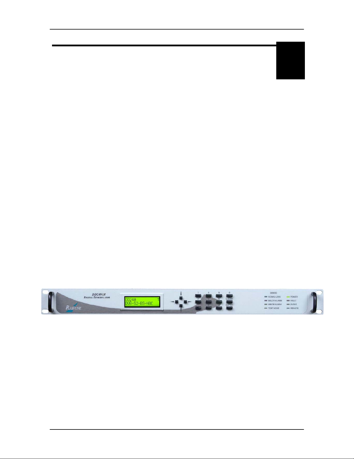
Radyne Corporation’s DD240XR family of High-Speed Demodulators is the ideal choice to meet
the exacting standards of high data-rate Video, Internet and Fiber Restoral Satellite Applications.
The DD240XR supports both DVB-S and DVB-S2 Broadcast Services. The DVB-S supports
QPSK, 8PSK and 16QAM applications with symbol rates up to 45 Msps and the DVB-S2 supports
QPSK, 8PSK and 16APSK applications with symbol rates of 2 to 45 Msps. With a variety of data
interfaces available, the DD240XR is configurable to meet high-speed satellite applications.
The powerful new onboard Monitor and Control (M&C) processor has the unique capability to
download firmware and enhance features from a field-changeable PCMCIA card. Offering
unprecedented flexibility, this feature represents a new level of Radyne Corporation’s outstanding
Customer Support. Additionally, features are added to the installed equipment base with extreme
ease, allowing the equipment to expand with changes in service while lowering initial installation
budgets.
The Demodulator offers a frequency-agile IF Input from 50 to 180 MHz (70/140), or 950 to 2150
MHz (L-Band) in 1Hz steps. Variable data rates for DVB-S (188 Mode) are from 2 Mbps to 145
Mbps and variable rates for DVB-S2 are from 1 Mbps to 160 Mbps.
Additional features include the choice of remotely interfacing through one of three onboard
connections: 10 BaseT/100 Base-T Ethernet, RS-485, or RS-232. The familiar Radyne Front
Panel (Figure 1-1) offers push-button control of all features and a backlit LCD display. Menus are
specifically designed for ease of use and quick online operation as well as changes in all
modulator configurations.
An optional 1:1 Redundancy Control Switch (RCS11) is available to provide the DD240XR with
superior system reliability.
Figure 1-1. DD240XR
MN-DD240XR – Rev. E 1-1
Page 12

Introduction DD240XR High-Speed Digital Demodulator
1-2 MN-DD240XR – Rev. E
Page 13

DD240XR High-Speed Digital Demodulator Installation
2
Installation
2.0 Installation Requirements
The DD240XR can be installed within any standard 19-inch equipment cabinet or rack, and
requires one rack unit (RU) mounting space (1.75 inches) vertically and 17 inches of depth.
Including cabling, a minimum of 20-inches of rack depth is required. The rear panel of the DD240
is designed to have power enter from the left and IF cabling enter from the right when viewed from
the rear of the unit. Data and control cabling can enter from either side although they are closer to
the center. The unit can be placed on a table or suitable surface if required.
There are no user-serviceable parts or configuration settings located inside
the DD240XR
power supply module. DO NOT open the DD240XR
circumstances.
Before initially applying power to the unit, it is a good idea to disconnect
the transmit output from the operating ground station equipment. This is
especially true if the current DD240XR configuration settings are unknown,
where incorrect setting could disrupt exis ting communications traffic.
Earth connection is essential before connecting power to the DD240XR due
to high leakage curr ent.
The DD240XR contains a Lithium Battery. DANGER OF EXPLOSION
if the battery is incorrectly replaced. Replace only with the same or
equivalent type recommended by the manufacturer. Dispose of used
batteries in accordance with manufacturer's instructions.
chassis. There is a potential shock hazard in ternally at the
chassis under any
exists
MN-DD240XR – Rev. E 2-1
Page 14

Installation DD240XR High-Speed Digital Demodulator
2.1 Unpacking
The DD240XR Demodulator was carefully packaged to avoid damage and should arrive complete
with the following items for proper installation:
DD240XR Unit
PCMCIA Card (May be installed, depending upon configuration. If no card is
installed, the unit has been factory configured)
Power Cord, 6 foot with Applicable AC Connector
Installation and Operation Manual.
2.2 Removal and Assembly
Carefully unpack the unit and ensure that all of the above items are in the carton. If the Prime AC
power available at the installation site requires a different power cord/AC connector, then
arrangements to receive the proper device will be necessary before proceeding with the
installation.
The DD240XR modulator is shipped fully assembled. It does not require removal of the covers for
any purpose in installation. The only replaceable assembly in the unit is the data interface and is
not intended to be accomplished in the field. If the AC power connector is the wrong type for the
installation, either the cable or the power connector should be replaced. The power supply itself is
designed for universal application using from 100 to 240 VAC, 50 to 60 Hz, < 40 W.
2.3 Mounting Considerations
When mounted in an equipment rack, adequate ventilation must be provided. The ambient
temperature in the rack should be between 10° and 35° C, and held constant for best equipment
operation. The air available to the rack should be clean and relatively dry. The DD240XR units
may be stacked one on top of the other up to a maximum of 10 consecutive units before providing
a 1 RU space for airflow.
Do not mount the DD240XR in an unprotected outdoor location where there is direct contact with
rain, snow, wind or sun. The DD240XR is designed for indoor applications only.
The only tools required for rack mounting the DD240XR
an appropriate screwdriver. Rack mount brackets are an integral part of the cast front bezel of the
unit and are not removable.
Shielded cables with the shield terminated to the conductive back shells are required in order to
meet EMC directives. Cables with insulation flammability ratings of 94 VO or better are required
in order to meet low voltage directives.
Earth connection is essential before connecting power to the DD240XR due to High Leakage
Current.
is a set of four rack-mounting screws and
2-2 MN-DD240XR – Rev. E
Page 15

DD240XR High-Speed Digital Demodulator Installation
2.4 Demodulator Checkout
The following descriptions assume that the DD240XR is installed in a suitable location with prime
AC power and supporting equipment available.
2.4.1 Initial Power-Up
Before initial power up of the DD240XR, it is a good idea to disconnect
the transmit output from the operating ground station equipment. This is
especially true if the current demodulator configuration settings are
unknown, where incorrect setting could disrupt existing communications
traffic. New units from the factory are normally shipped in a default
configuration which includes setting the transmit carrier off.
Turn the unit ‘ON’ by placing the rear panel switch (above the power entry connector) to the ‘ON’
position. Upon initial and subsequent power-ups, the DD240XR microprocessor will test itself and
several of its components before beginning its main Monitor/Control program. These power-up
diagnostics show no results if successful. If a failure is detected, the Fault LED is illuminated.
The initial field checkout of the DD240XR can be accomplished from the Front Panel, Terminal
Port, Remote Port, or Ethernet Port.
MN-DD240XR – Rev. E 2-3
Page 16

Page 17

Installation DD240XR High-Speed Digital Demodulator
2-4 MN-DD240XR – Rev. E
Page 18

Page 19
DD240XR High-Speed Digital Demodulator Operation
3
Theory of Operation
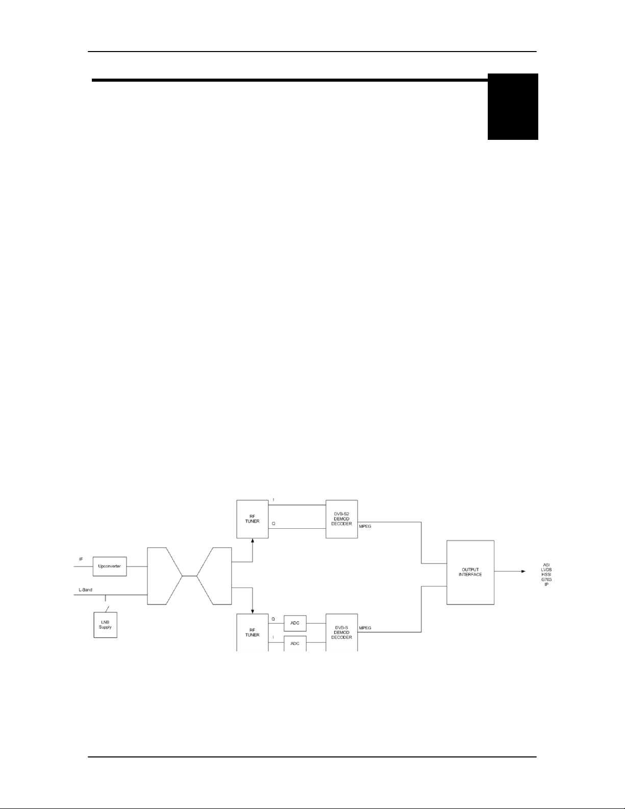
3.0 Theory of Operation
The basic theory of operation for each platform is similar. The DD240XR is capable of supporting
L-band from 950-2150 MHz and can be upgraded to include IF frequencies of 50-180 MHz in the
same package. If the unit is configured to receive analog signal in the IF band of 50-180 MHz, the
signal is converted to L-band. The L-band signal is then tuned and digitally demodulated. The
incoming I&Q symbols are then filtered decoded, and mapped to data bits. The network
specification selected will determine if the data stream supports DVB-S or DVB-S2 formats.
The DVB-S Network specification complies with both EN300-421 and EN301-210 ETSI
specifications. EN300-421 supports QPSK demodulation and EN301-210 supports higher
demodulation rates of 8PSK and 16QAM. The resulting data stream is FEC decoded by the
Viterbi (K=7) inner convolutional/trellis decoder, de-interleaved and further FEC decoded by the
outer Reed Solomon 204/188 decoder.
The DVB-S2 Network specification complies with the next generation DVB open standard
supported by EN302-307. At the core of this standard is a powerful Bose-ChaudhuriHocquenghem BCH decoding and concatenated Low-Density Parity Check (LDPC). The
DD240XR only supports normative features identified by the DVB-S2 Broadcast services. The
Broadcast Services mode of operation supports Constant Coding and modulation (CCM) system
and single transport streams. Operating in this mode allow for a variety of FEC rates to be used
with QPSK, 8PSK and 16APSK modulation schemes.
The decoded data is then sent through a deframer to provide terrestrial data that is either
unframed, 188 byte DVB format or 204 byte DVB format. Based on the type of terrestrial interface
installed, the data stream is re-clocked through an optional Doppler buffer, serialized and
converted through the appropriate physical layer interface. A functional block diagram is shown in
Figure 3-1.
Figure 3-1. Functional Bl o ck Diagram
MN-DD240XR – Rev. E 3-1
Page 20

Operation DD240XR High-Speed Digital Demodulator
3-2 MN-DD240XR – Rev. E
Page 21
DD240XR High-Speed Digital Demodulator User Interfaces
4
1 2 3
4
User Interfaces
4.0 User Interfaces
There are four User Interfaces available for the DD240 family of products. These are:
Front Panel
Remote Port
Ethernet Port
Terminal
4.1 Front Panel User Interface
The Front Panel of the DD240XR allows for complete control and monitor of all DD240XR
parameters and functions via a keypad, LCD display and status LEDs.
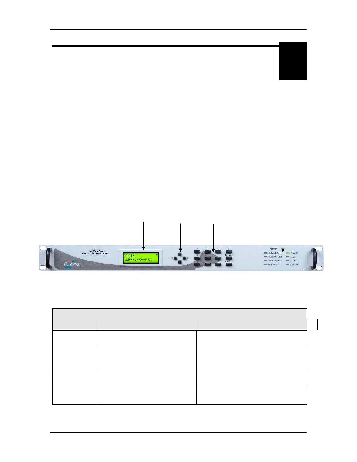
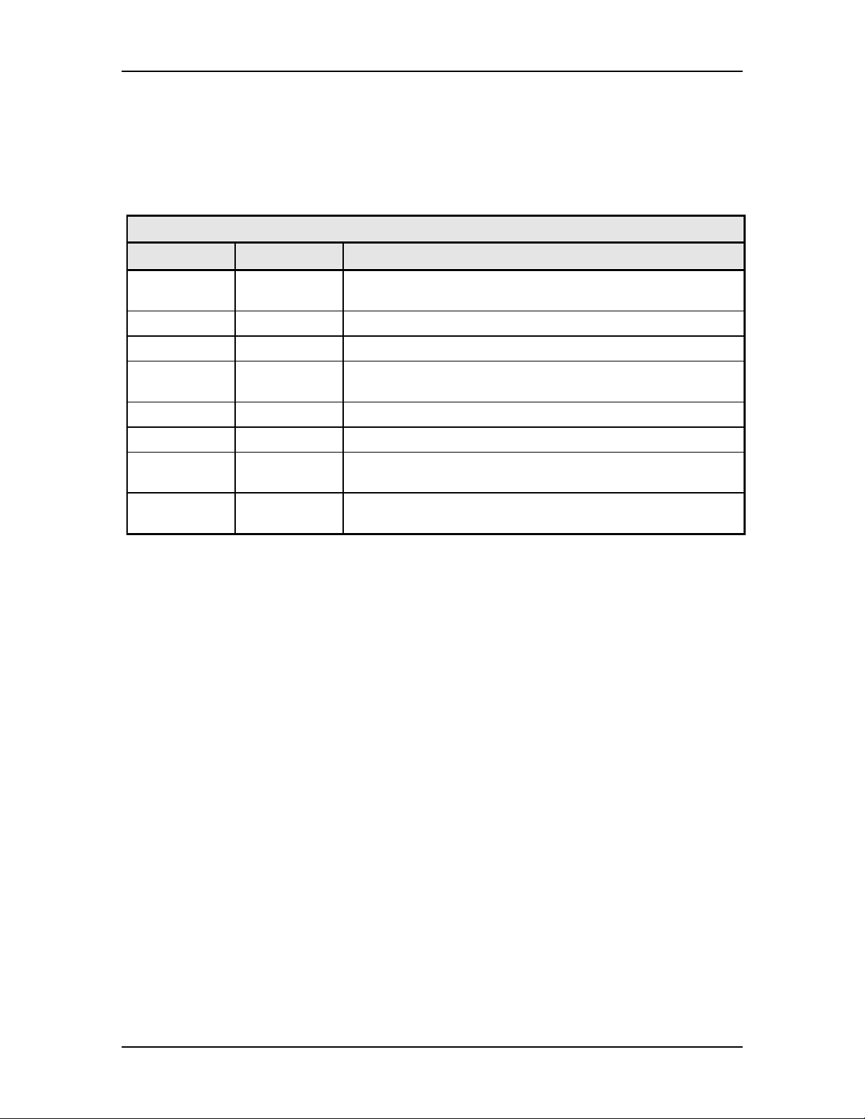
The Front Panel layout is shown in Figure 4−1, showing the location and labeling of the Front
Panel. The Front Panel is divided into four functional areas: the LCD Front Panel Display, the
Cursor Control Arrows, the Numeric Keypad and the LED Indicators, each described below in
Table 4-1.
Figure 4-1. DD240XR Front Panel
Table 4-1.
Item Number Description Function
1 Front Panel LCD Display Displays DD240XR Operating
Parameters and Configuration Data.
2 Cursor Control Arrows Controls the up, down, right and left
motion of the cursor in the LCD Display
Window.
3 Numeric Keypad Allows the entry of numeric data and
Clear and Enter Function Keys.
4 Front Panel LED Indicators See Section 4.1.4 below for an itemized
description of these LEDs.
TM115 – Rev. 1.2 4-1
Page 22

User Interfaces DD240XR High-Speed Digital Demodulator
↑ ↓ ← →
←
→
4.1.1 Front Panel LCD Display
The Front Panel display is a 2 line by 16-character LCD display. The display is lighted and the
brightness can be set to increase when the Front Panel is currently in use. The LCD display
automatically dims after a period of inactivity. The display has two distinct areas showing current
information. The upper area shows the current parameter being monitored, such as ‘Frequency’
or ‘Data Rate’. The lower line shows the current value of that parameter. The LCD display is a
single entry window into the large matrix of parameters that can be monitored and set from the
Front Panel.
4.1.2 Cursor Control Arrows
The ‘Cursor’ or ‘Arrow’ Keys (
↑), (↓), (→), (←), are used to navigate the parameter currently being
monitored or controlled. Table 4-2 describes the key functions available at the Front Panel.
Table 4-2.
Edit Mode Key Functions (Front P anel Only)
Parameter
Type
Fixed Point
Decimal
Unsigned
Hexadecimal
Enumerated N/A Previous
Date/ Time Changes Digit
IP Address Changes Digit Increments
Text Strings Changes
0 – 9
Changes Digit Toggles ±
Changes Digit Increments
Character
(If Signed)
Digit Value
Value in
List
N/A N/A Moves
Digit Value
Increments
Character
Value
Toggles ±
(If Signed)
Decrements
Digit Value
Next
Value in
List
Decrements
Digit Value
Decrements
Character
Value
Moves
Cursor 1
Position
Left
Moves
Cursor 1
Position
Left
N/A N/A N/A N/A
Cursor 1
Position
Left
Moves
Cursor 1
Position
Left
Moves
Cursor 1
Position
Left
Moves
Cursor 1
Position
Right
Moves
Cursor 1
Position
Right
Moves
Cursor 1
Position
Right
Moves
Cursor 1
Position
Right
Moves
Cursor 1
Position
Right
‘Clear’ &
N/A N/A
N/A N/A
N/A N/A
N/A N/A
Clears to
Left of
Cursor
Inclusive
Clears to
Inclusive
‘Clear’ &
Right of
Cursor
4.1.3 Front Panel Keypad
The Front Panel Keypad consists of a 10-key numeric entry with 2 additional keys for the ‘Enter’
and ‘Clear’ functions.
4-2 MN-DD240XR – Rev. E
Page 23
DD240XR High-Speed Digital Demodulator User Interfaces
4.1.4 Front Panel LED I ndi cators
Eight LEDs on the DD240XR Front Panel (Refer to Table 4-3) indicate the status of the
DD240XRs operation. The LED colors maintain a consistent meaning. Green signifies that the
indication is appropriate for normal operation. Yellow means that there is a condition not proper
for normal operation, and Red indicates a fault condition that will result in lost communications.
Table 4-3.
LED Color Function
Carrier Lock Green Indicates the DD240XR Demodulator and Decoder are
locked.
Major Alarm Red Indicates that the receive direction has failed, losing traffic.
Minor Alarm Yellow Indicates a receive warning condition exists.
Test Mode Yellow Indicates the demodulator is involved in current test mode
activity.
Power Green Indicates the DD240XR unit is currently powered up.
Fault Red Indicates a common fault exists such as power out of spec.
Event Yellow Indicates that the events have been logged into the event
buffer.
Remote Green Indicates that the unit is set to respond to the remote control
or terminal input.
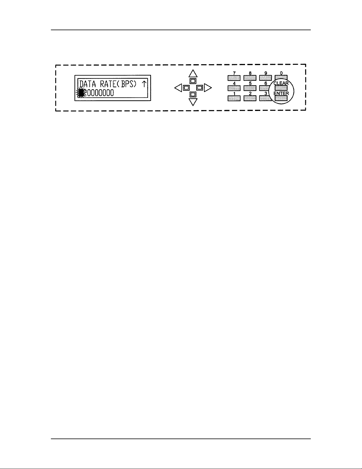
4.1.5 Parameter Setup
The four arrow keys (
menu tree and select the parameter to be set. After arriving at a parameter that needs to be
modified, depress <ENTER>. The first space of the modifiable parameter highlights (blinks) and
is ready for a new parameter to be entered. After entering the new parameter using the keypad
(Refer to Figure 4-3), depress <ENTER> to lock in the new parameter. If a change needs to be
made prior to pressing <ENTER>, depress <CLEAR> and the display defaults back to the original
parameter. Depress <ENTER> again and re-enter the new parameters followed by <ENTER>.
Following a valid input, the DD240XR will place the new setting into the nonvolatile SRAM making
it available immediately and available the next time the unit is powered-up.
↑), (↓), (→), (←), to the right of the LCD display are used to navigate the
MN-DD240XR – Rev. E 4-3
Page 24
User Interfaces DD240XR High-Speed Digital Demodulator
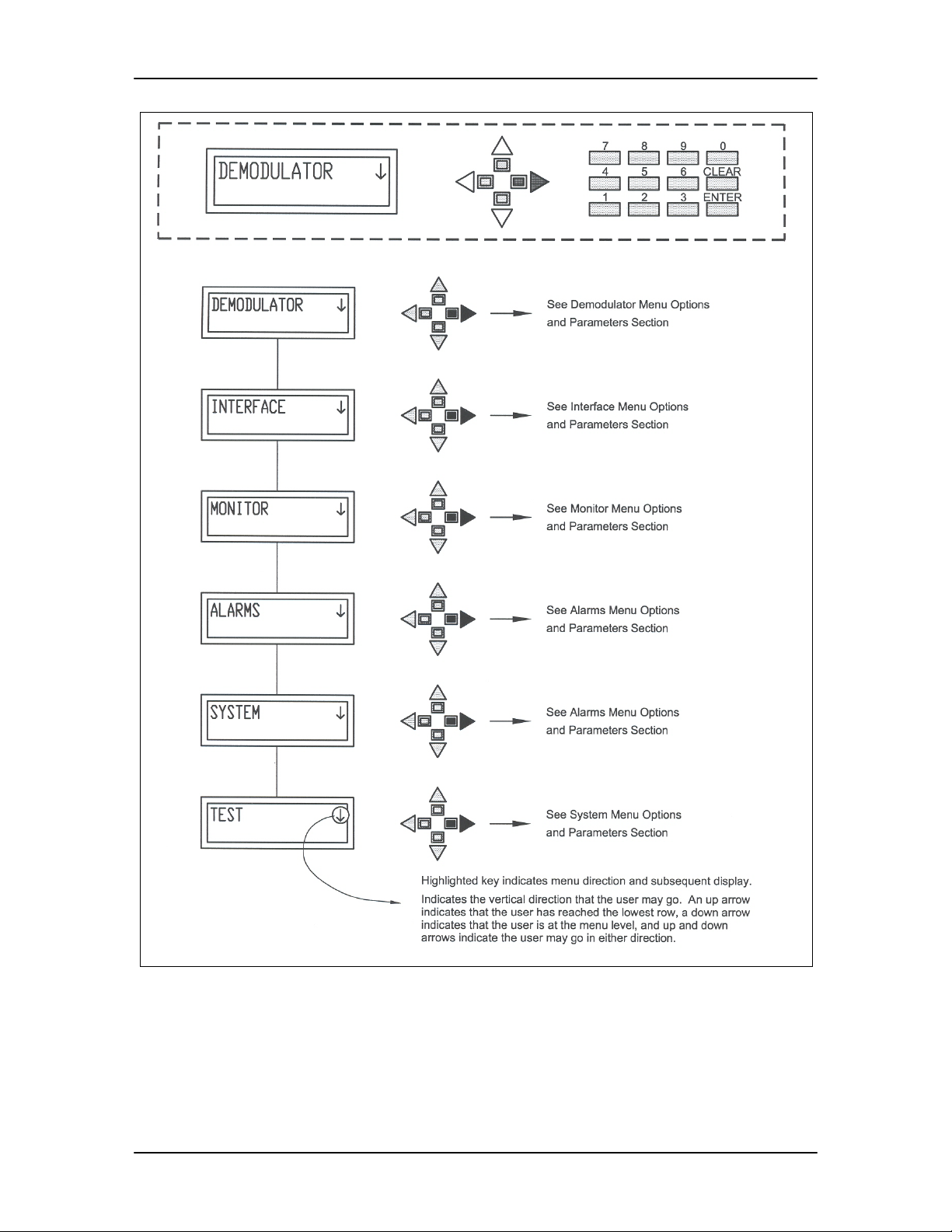
Figure 4-2. DD240XR Main Programming Menu
4-4 MN-DD240XR – Rev. E
Page 25
DD240XR High-Speed Digital Demodulator User Interfaces
Note: If at any time the use r wishes to abort the changes being made, depress <CLEAR>
to begin again.
Figure 4-3. Entering New Parameters
4.2 Front Panel Control Scre en Menus
The DD240XR Front Panel Control Screens are broken down into sections under several Main
Menus.
4.2.1 Main Menus
Demodulator
Interface
Monitor
Alarms
System
Test
4.2.2 Demodulator Menu Options and Paramete r s
NETWORK SPEC: {DVBS, DVB-S2-BS-NBC}
FREQUENCY (MHz): {NNNN.NNNNNN}
Carrier Frequency – Enter in 1 Hz increments where
NNNN.NNNNNN is the frequency in MHz.
Select a carrier with 1 Hz steps.
MODULATION: DVB-S: {8PSK, 16QAM},
DVB-S2 {QPSK, 8PSK, 16APSK}
Displays the Modulation Type
INNER FEC RATE: DVB-S QPSK: 1/2, 2/3, 3/4, 5/6, 7/8
DVB-S 8PSK: 2/3, 5/6, 8/9
DVB-S 16QAM: 3/4, 7/8
DVB-S2 QPSK: 1/2, 2/3, 3/5, 3/4, 4/5, 5/6, 8/9, 9/10
DVB-S2 8PSK: 2/3, 3/5, 3/4, 5/6, 8/9, 9/10
DVB-S2 16APSK: 2/3, 3/4, 4/5, 5/6, 8/9, 9/10
Note: 9/10 only available with normal FEC frames
MN-DD240XR – Rev. E 4-5
Page 26

User Interfaces DD240XR High-Speed Digital Demodulator
SAT FRAMING FECFRAME
Select NORMAL n_ldpc = 64,800 or
SHORT n_ldpc = 16,200
DATA RATE (bps): Terrestrial Data Rate:
Enter in 1 bps increments from 2,000,000 to 160,000,000
BPS.
SYMB RATE (sps): Output Symbol Rate:
Enter in 1 sps increments from 2,000,000 to 45,000,000
sps.
SPECTRUM: {AUTO DETECT}
This is the commanded spectrum detection. Select
NORMAL or INVERTED. This display is not user
selectable for DVBS 8PSK or 16QAM, where it is fixed
as AUTO DETECT.
ROLL OFF: DVB-S: {0.20, 0.35} for QPSK/8PSK/16QAM.
DVB-S2 {20, .25, .35} for QPSK/8PSK/16APSK
PILOT SYMBOLS: {ON, OFF}
Used to enable pilot symbol for DVB-S2 only
GOLD SEQ N: {012345}
Gold code sequence number for DVB-S2 only
LAST RATE CTRL: {SYMBOL RATE, DATA RATE, AUTO}
Indicates the rate (symbol or data) which is maintained
when associated parameters (i.e. Modulation, Inner FEC
Code Rate, Terr Framing) are changed. For example, if
the Last Rate Control is set to “Symbol Rate” and the
modulation is subsequently changed, the system will
attempt to maintain the same symbol rate by adjusting
the data rate. If the Last Rate Control is set to “Data
Rate” and the modulation is subsequently changed, the
system will attempt to maintain the same data rate by
adjusting the symbol rate.
4-6 MN-DD240XR – Rev. E
Page 27
DD240XR High-Speed Digital Demodulator User Interfaces
The “Auto” Setting of Last Rate Control causes the last
explicitly changed rate (symbol or data) to be maintained
when associated parameters are changed. For
example, if the last rate control is set to “Auto” and the
Data Rate is subsequently explicitly changed, any
subsequent changes to Modulation or Inner FEC Rate
would cause the symbol rate to be adjusted in order to
maintain the Data Rate.
ACQ RANGE: {Variable in one Hz steps}
Acquisition Range – Allows the user to set the carrier
acquisition sweep range. Sweep rate range changes
based on Data rate and FEC rate.
LNB POWER: {ON, OFF}
Used to enable the LNB 18V DC Output to J6.
EBNO FLOOR (dB): {1, 15}
This screen is used for setting the level at which an
Eb/No Alarm should be indicated. This will occur when
the measured Eb/No value is less than the floor level and
an Event and Alarm will be generated.
4.2.3 Interface Menu Options and Parameters
INTERFACE TYPE: {ASI, Advanced ASI, HSSI, RS-442 Serial, M2P
Parallel, DVB Parallel, G.703 STS1, G.703.E3,
G.703.T3, ECL BAL/UNBAL, ETHERNET GIGE}
Allows the user to enter the Terrestrial Interface type.
Only the Interface types that are installed may be selected.
When a G.703 interface is selected the data rate and symbol rates are dictated by the
interface.
MN-DD240XR – Rev. E 4-7
Page 28
User Interfaces DD240XR High-Speed Digital Demodulator
TERR FRAMING: {None, DVB 188, DVB 204}
Terrestrial Framing – Allows the user to choose framing
packet. None equals 187 framing.
When configured with an Ethernet Interface, TERR FRAMING is always 188 framing.
TERR STREAMING: {Byte Output, Pac ket Output}
Only applies when ASI interface is installed
DATA POLARITY: {NORMAL, INVERTED}
This allows user to invert the data.
CLOCK POLARITY: {NORMAL, INVERTED}
(This menu is not displayed when ASI interface is
installed)
Rx Clock Polarity – Allows the user to specify the clock
sense. This should be set the same as the Modulator
Source.
BUFF CLOCK SRC: {RX SAT, EXC DIR, EXC REF PLL}
When G703 Interface is installed the Buffer Clock
Source options are below are available. All other
interfaces may display RX SAT.
RX SAT - Clock is recovered from the satellite data
transmission.
EXC DIR – Clock is provided by an external clock
source. Not all terrestrial interfaces include a Doppler
buffer.
EXC REF PLL – Clock is provided by an external clock
source and passed through a phase locked loop. Not all
terrestrial interfaces include a Doppler buffer.
RX SAT Clock is the standard clock with most interfaces. External clocks are available
only if the interface i s buffer capable. If the interface is not buffer capable, the EXC
Options (BUFF CLK SRC, EXC REF CLOCK, RX BUFFER SIZE, and RX BUFFER RESET)
will not be displayed.
4-8 MN-DD240XR – Rev. E
Page 29

DD240XR High-Speed Digital Demodulator User Interfaces
EXC REF CLOCK: {1.000, 1.544, 2.000, 2.048, 5.000, 6.312, 8.448, 10.000
MHz} (This menu not displayed when Ethernet
interface is installed)
Rx Reference Clock Rate
This menu allows the user to specify the reference clock
rate. The rates are the most commonly used and
include T1, E1, T2 and E2 references. Not all terrestrial
interfaces include a Doppler buffer.
RX BUFFER SIZE: Allows the user to specify the buffer depth. Enter in
1 msec increments from 00 to 64. A value of 0 will
disable, bypass, buffering and the demodulator will then
use the RX SAT as the clock source. Not all terrestrial
interfaces include a Doppler buffer.
TERR ETHERNET: This menu is displayed when Ethernet interface is
installed. This interface supports MPEG over IP traffic.
This menu can be configured to support Ethernet Bridge
option or PRO MPEG COP3 option. Each option
supports different menu structures. The following items
are available under the Terrestrial Ethernet menu:
PROG ETH FLASH: {PRESS CLEAR}
When Bridge option is selected, the PROG ETH FLASH
menu is the only menu displayed. The PROG ETH
FLASH allows the user to select the desired Ethernet
protocol option. The protocols supported by the
DD240XR are Ethernet Bridge or Pro MPEG COP 3. If
unit is configured for Bridge option, the user can activate
the PRO MPEG COP3 option by pressing the <Down
Arrow>. Once COP3 is reflected on the front panel,
press the <Clear> button to activate the option. The
front panel will display a sequence process indicating
that the flash is being Erased, Programmed, and
Verified. At the end of sequence the final status will be
displayed as either Successful or Unsuccessful.
THE FOLLOWING MENUS ARE DISPLAYED W HE N THE TERRESTRIAL ETHERNET
INTERFACE IS CONFIGURED FOR PRO MPEG COP 3.
TERR MAC ADDR: {0123456789AB}
This menu displays the MAC addresses of the Ethernet
Data Interface card. Entering any non-zero value in this
field will cause the EDI to use the entered value as its
MAC address.
Entering a value of all zeros will cause the Ethernet Data
Interface to revert back to its original MAC address.
MN-DD240XR – Rev. E 4-9
Page 30

User Interfaces DD240XR High-Speed Digital Demodulator
could be the MAC address of the final destination or the MAC address of the first ro u ter
through which this data will pass. The Ethernet Data Interface will not output any data
MODE SELECTION:
UDP PACKETS: The Demodulator outputs seven MPEG
packets encapsulated in UDP datagram.
COP3 RTP: The Demodulator outputs seven MPEG
packets encapsulated in a COP3 compliant RTP
datagram.
COP3 RTP FEC: The Demodulator outputs COP3
compliant column FEC packets in addition to the RTP
datagram.
IP ADDR: {XXX.XXX.XXX.XXX}
This is the IP address to be used by the Ethernet Data
Interface. This will be the source IP address for all
Ethernet traffic generated by this interface.
UDP PORT: {XXXXX}
This is the source UDP port to be used by the Ethernet
Data Interface.
DEST IP ADDR: {XXX.XXX.XXX.XXX}
This is the destination IP address that the Ethernet Data
Interface will send all Ethernet data traffic to.
DEST UDP PORT: {XXXXX}
This is the destination UDP port that the Ethernet Data
Interface will send all MPEG traffic to.
Unicast Destination IP Addresses
When the destination address is a Unicast address
(000.000.000.000 thru 223.255.255.255) the Ethernet Data Interface will use an ARP
Request to determine the Destination MAC address to which the data will be sent. This
until it receives an ARP Reply to its ARP Request.
4-10 MN-DD240XR – Rev. E
Page 31

DD240XR High-Speed Digital Demodulator User Interfaces
Multicast Destination IP Addresses
When the destination address is a Multicast address
(224 000.000.000 thru 255.255.255.255) the Ethernet Data Interface will construct the
appropriate Destination Multicast MAC address based upon the Destination Multicast
IP Address. The Ethernet Data Interface will then transmit multicast data packets to
the destination without performing any other handshaking or IGMP message
processing.
BLOCK ALIGNED: {YES or NO]
This menu is only visible when COP 3 RTP FEC is
selected.
Yes: selects block aligned Column FEC.
No: selects non-block aligned Column FEC. Each
column is offset by 1, as illustrated in Informative Annex
A of COP 3 release 2.
FEC COLUMN L {X}
This menu is only visible when COP 3 RTP FEC is
selected.
This selects the number of columns used by the FEC
calculation.
FEC COLUMN D {X}
This menu is only visible when COP 3 RTP FEC is
selected.
This selects the number of rows used by the FEC
calculation.
Constraints on L and D values
L and D have the following constraints
4 <= L <= 20
4 <= D <= 20
L * D <= 100
MN-DD240XR – Rev. E 4-11
Page 32

User Interfaces DD240XR High-Speed Digital Demodulator
PROG ETH FLASH: {PRESS CLEAR}
The PROG ETH FLASH allows the user to select the
desired Ethernet protocol. The protocol options
supported by the DD240XR are Pro MPEG COP 3 or
Bridge. If unit is configured for COP 3, the user can
activate Bridge option by pressing the <Down Arrow>.
Once Bridge is reflected on the front panel, press the
<Clear> button to activate the Bridge protocol. The front
panel will display a sequence process indicating that the
flash is being Erased, Programmed, and Verified. At the
end of sequence the final status will be displayed as
either Successful or Unsuccessful.
4.2.4 Monitor Menu Options and Parameters
EVENTS: Event Buff:
Display/Clear logged events and faults.
Depressing <ENTER> on the Front Panel allows the user
to view logged events. Depressing <ENTER> again
allows normal menu traversal to continue.
ERASE EVENTS: PRESS CLEAR
Clear all logged events and faults from the event buffer.
INPUT LVL (dBm): {0 - 100}
This screen is used to display the current signal level
being detected by the demodulator.
EBNO (dB): {XXXNN.NN}
NN.NN = the current Eb/No in dB. XXX may be one of
the following:
= The Eb/No is within the valid range.
> The Eb/No is above the valid range. The
displayed value is irrelevant and is accompanied
by an Alarm LED.
< The Eb/No is below the valid range. The
displayed value is irrelevant and is accompanied
by an Alarm LED.
“???” The Eb/No is invalid. The displayed value is
irrelevant and is accompanied by an Alarm LED.
BER AFTER OFEC: DVBS only
{1.5 x 10
{7.7 x 10
{7.7 x 10
This screen displays the estimated Bit Error Rate (BER)
after decoding.
MPEG PER: DVBS2 only
-15
, 3.7x 10⁻² (in QPSK)}
-16
, 1.9x 10⁻² (in 8PSK)}
-16
, 1.9x 10⁻² (in 16QAM)}
4-12 MN-DD240XR – Rev. E
Page 33

DD240XR High-Speed Digital Demodulator User Interfaces
This screen displays the ratio of mpeg packets with CRC
errors to mpeg packets with no errors. No CRC errors =
0, every packet with a CRC error = 1.
FREQ OFFSET (Hz): {-2.5 MHz, +2.5 MHz}
This screen displays the actual carrier frequency offset
from the programmed frequency.
SYMB RATE OFFSET (Hz): {-1000 Hz, 1000 Hz}
This screen displays the symbol rate recovered as an
offset from the programmed symbol rate.
SPECTRUM: {NORMAL, INVERTED}
This is the spectrum detection as detected by the internal
carrier subsystem.
RX BUFFER LEVEL: This screen displays the buffer level in percent full.
Displayed in buffer capable units only
RX BUFFER RESET: Allows the user to re-center, and therefore, reset the
buffer. Pressing the <ENTER> button will force a re-
centering and will result in a momentary loss of data or
frame slip. Not all terrestrial interfaces include a Doppler
buffer.
+5V SUPPLY: Display the currently measured +5 VDC power supply.
+12V SUPPLY: Display the currently measured +12 VDC power supply.
-12V SUPPLY: Display the currently measured -12 VDC power supply.
Only on units with a HSSI or ECL BAL/UNBAL Terrestrial
Interface installed.
+24V SUPPLY: Display the currently measured +24 VDC power supply.
MONITOR - The following new items are available under the Monitor menu
LINK STATUS: {1 GIG FULL, 100 MEG FULL, NO LINK}
This menu displays the current terrestrial link status and
rate at which the Ethernet Data Interface has established
a physical connection.
1 GIG FULL - One Gigabit Full Duplex (1000BaseT)
100 MEG FULL 100 Megabits Full Duplex (100BaseT)
NO LINK - No connection.
TOTAL PACKETS: {0123456789}
This menu displays the total number of data packets that
have been output by the Ethernet Data Interface. This is
either the number of UDP packets in UDP mode, or the
number of RTP packets in COP3 RTP and COP3 RTP
FEC mode.
FEC PACKETS: {0123456789}
MN-DD240XR – Rev. E 4-13
Page 34

User Interfaces DD240XR High-Speed Digital Demodulator
This menu is only visible when COP 3 RTP FEC is
selected.
This menu displays the total number of FEC packets that
have been output by the Ethernet Data Interface in
COP3 RTP FEC mode.
CLEAR STATUS: (ENTER))
Pressing Enter will reset the Total Packet and FEC
Packet counters.
4.2.5 Alarms Menu Options and Parameters
CURRENT ALARM (Menu):
RX MAJOR (Menu):
Status
SIGNAL LOCK: {Pass/Fail, Unmasked/Masked}
This screen is used to enable/disable alarms when the
SYNTH PLL: {Pass/Fail, Unmasked/Masked}
This screen is used to enable/disable alarms when the
INPUT LEVEL: {Pass/Fail, Unmasked/Masked}
This screen is used to enable/disable alarms when the
CLOCK ACTIVITY: {Pass/Fail, Unmasked/Masked}
CARRIER COMM: {Pass/Fail, Unmasked/Masked}
This screen is used to enable/disable alarms when
DEMOD COMM: {Pass/Fail, Unmasked/Masked}
This screen is used to enable/disable alarms when
FPGA CONFIG:
DJIT CFG: {Pass/Fail}
This screen is used to enable/disable alarms when DJIT
TERR INTFC CFG: {Pass/Fail}
This screen is used to enable/disable alarms when the
RX MINOR (Menu):
Displays Current Alarm Status.
Edit Table
Carrier Lock is not present.
On-Board Phase-Locked Loop cannot lock to the input
signal.
Input Level is too low.
communications have failed with the Internal Carrier
Control Subsystem.
communications have failed with the Internal
Demodulation Control Subsystem.
{Pass/Fail, Unmasked/Masked}
FPGA has failed to configure appropriately.
Terrestrial Card FPGA has failed to configure
appropriately.
4-14 MN-DD240XR – Rev. E
Page 35

DD240XR High-Speed Digital Demodulator User Interfaces
DD240XR only displays buffer status and alarm prompts for terrestrial interfaces that
support Doppler buffering.
DATA ACTIVITY: {Pass/Fail, Unmasked/Masked}
This screen is used to enable/disable alarms when data
is not detected in the signal.
BUFF UNDERFLOW: {Pass/Fail, Unmasked/Masked}
This screen is used to enable/disable the alarm which
occurs when the signal buffer completely empties and
resets. This menu is only available if the terrestrial
interface is buffer capable.
BUFF NEAR EMPTY: {Pass/Fail, Unmasked/Masked}
This screen is used to enable/disable the alarm which
occurs when the signal buffer reaches a near empty
value of 10%. This menu is only available if the
terrestrial interface is buffer capable.
BUFF NEAR FULL: {Pass/Fail, Unmasked/Masked}
This screen is used to enable/disable the alarm which
occurs when the signal buffer reaches a near full value of
90%. This menu is only available if the terrestrial
interface is buffer capable.
BUFF OVERLFOW: {Pass/Fail, Unmasked/Masked}
This screen is used to enable/disable the alarm which
occurs when the signal buffer completely fills and resets.
This menu is only available if the terrestrial interface is
buffer capable.
EXC CLOCK: {Pass/Fail, Unmasked/Masked}
This screen is used to enable/disable the alarm which
occurs when the signal buffer external clock is no longer
detected. This menu is only available if the terrestrial
interface is buffer capable.
EXC PLL LOCK: {Pass/Fail, Unmasked/Masked}
This screen is used to enable/disable the alarm which
occurs when the signal buffer external clock being routed
to the terrestrial interface PLL is no longer detected.
This menu is only available if the terrestrial interface is
buffer capable.
DEMOD LOCK: {Pass/Fail, Unmasked/Masked}
MN-DD240XR – Rev. E 4-15
Page 36

User Interfaces DD240XR High-Speed Digital Demodulator
This screen is used to enable/disable alarms when the
demodulator has lost lock.
IFEC LOCK: {Pass/Fail, Unmasked/Masked}
This screen is used to enable/disable alarms when the
Inner Forward Error Correction has encountered too
many errors.
OFEC LOCK: {Pass/Fail, Unmasked/Masked}
This screen is used to enable/disable alarms when the
Outer Forward Error Correction has encountered too
many errors.
FRAME SYNC: {Pass/Fail, Unmasked/Masked}
This screen is used to enable/disable alarms when the
DVB Frame Sync Byte (0 x 47) is not recovered from the
Input Stream.
EBNO: {Pass/Fail, Unmasked/Masked}
This screen is used to enable/disable alarms when the
Eb/No value has fallen below the floor alarm value.
IP DEST ADDR {Unmasked/Masked}}
Fail indicates the EDI has not received an ARP reply to
its ARP requests and thus has not been able to resolve
the destination MAC address.
ETH LINK {Unmasked/Masked}
Fail indicates that the Ethernet Data Interface has not
been able to establish a valid physical connection on its
Ethernet data port.
COMMON (Menu):
+5V SUPPLY: {Pass/Fail, Unmasked/Masked}
This screen is used to enable/disable alarms when the
+5 V Power Supply has drifted outside specifications.
+12V SUPPLY: {Pass/Fail, Unmasked/Masked}
This screen is used to enable/disable alarms when the
+12 V Power Supply has drifted outside specifications.
-12V SUPPLY: {Pass/Fail, Unmasked/Masked}
This screen is used to enable/disable alarms when the
-12 V Power Supply has drifted outside specifications.
Only on units with a HSSI or ECL BAL/UNBAL Terrestrial
Interface installed.
+24V SUPPLY: {Pass/Fail, Unmasked/Masked}
This screen is used to enable/disable alarms when the
+24 V Power Supply has drifted outside specifications.
DEMOD HW FAULT: {Pass/Fail, Unmasked/Masked}
4-16 MN-DD240XR – Rev. E
Page 37

DD240XR High-Speed Digital Demodulator User Interfaces
LATCHED ALARMS (Menu):
This menu duplicates the Current Alarm Menu, but
displays Latched Alarms instead of Current Alarms.
RX MAJOR (Menu):
Status
SIGNAL LOCK: {Pass/Fail}
The Carrier Lock is currently or has alarmed since last
clearing.
SYNTH PLL: {Pass/Fail}
The On-Board Phase-Locked Loop is currently or has
alarmed since last clearing.
INPUT LEVEL: {Pass/Fail}
The Input Level is currently or has alarmed since last
clearing.
CLOCK ACTIVITY: {Pass/Fail}
CARRIER COMM: {Pass/Fail}
Communications have failed with the Internal Carrier
Control Subsystem since the last clearing.
DEMOD COMM: {Pass/Fail}
Communications have failed with the Internal
Demodulation Control Subsystem since last clearing.
FPGA CONFIG:
{Pass/Fail}
DJIT CFG: {Pass/Fail}
The DJIT FPGA is currently or has alarmed since last
clearing.
TERR INTFC CFG: {Pass/Fail}
The Terrestrial Card FPGA is currently or has alarmed
since last clearing.
RX MINOR (Menu):
Status
DATA ACTIVITY: {Pass/Fail}
The Rx Data is currently or has alarmed since last
clearing.
BUFF UNDERFLOW: {Pass/Fail}
MN-DD240XR – Rev. E 4-17
Page 38

User Interfaces DD240XR High-Speed Digital Demodulator
The signal buffer has completely emptied and reset,
since latched alarms were last cleared. This menu is
only available if the terrestrial interface is buffer capable.
BUFF NEAR EMPTY: {Pass/Fail}
The signal buffer has reached a near empty value since
latched alarms were last cleared. This menu is only
available if the terrestrial interface is buffer capable.
BUFF NEAR FULL: {Pass/Fail}
The signal buffer has reached a near full value since
latched alarms were last cleared. This menu is only
available if the terrestrial interface is buffer capable.
BUFF OVERLFOW: {Pass/Fail}
The signal buffer has completely filled and reset, since
latched alarms were last cleared. This menu is only
available if the terrestrial interface is buffer capable.
EXC CLOCK: {Pass/Fail}
The signal buffer external clock detection has failed
since latched alarms were last cleared. This menu is
only available if the terrestrial interface is buffer capable.
EXC PLL LOCK: {Pass/Fail}
The signal buffer external clock being routed to the
terrestrial interface PLL lost detection since latched
alarms were last cleared. This menu is only available if
the terrestrial interface is buffer capable.
DEMOD LOCK: {Pass/Fail}
The Demod Lock is currently or has alarmed since last
clearing.
IFEC LOCK: {Pass/Fail}
The Inner Forward Error Correction is currently or has
alarmed since last clearing.
OFEC LOCK: {Pass/Fail}
The Outer Forward Error Correction is currently or has
alarmed since last clearing.
FRAME SYNC: {Pass/Fail}
The DVB Frame Sync is currently or has alarmed since
last clearing.
EBNO: {Pass/Fail}
The Eb/No is currently on has alarmed since last
clearing.
IP DEST ADDR {Pass/Fail}
4-18 MN-DD240XR – Rev. E
Page 39

DD240XR High-Speed Digital Demodulator User Interfaces
Fail indicates the EDI has not received an ARP reply to
its ARP requests and thus has not been able to resolve
the destination MAC address.
ETH LINK {Pass/Fail}
Fail indicates that the Ethernet Data Interface has not
been able to establish a valid physical connection on its
Ethernet data port.
COMMON (Menu):
+5V SUPPLY: {Pass/Fail}
The +5 V Supply is currently or has alarmed since last
+12V SUPPLY: {Pass/Fail}
The +12 V Supply is currently or has alarmed since last
-12V SUPPLY: {Pass/Fail}
-12 V Supply is currently or has alarmed since last
+24V SUPPLY: {Pass/Fail}
The +24 V Supply is currently or has alarmed since last
DEMOD HW FAULT: {Pass/Fail}
CLEAR LATCHED ALARMS: {False/True}
This screen is used to clear all latched alarms.
clearing.
clearing.
clearing. Only on units with a HSSI or ECL BAL/UNBAL
Terrestrial Interface installed.
clearing.
4.2.6 System Menu Options and Parameters
The System Screens are shown in Figure 4-10. These include:
DATE (MM/DD/YY): Displays the current date.
TIME (HH:MM:SS): Displays the current time.
FRONT PANEL (Menu):
BKLT LEVEL: {HIGH, MED, LOW, OFF}
Sets the backlight intensity level.
BKLT TIMEOUT: {0 – 99}
Allows the user to enter the amount of time in seconds
KEY CLICK: {ON, OFF}
Allows the user to choose between silent and audible
for the backlight to dim. Enter ‘0’ for no timeout.
button depression.
MN-DD240XR – Rev. E 4-19
Page 40

User Interfaces DD240XR High-Speed Digital Demodulator
MENU NAVIGATION: {STANDARD, FLOATING}
Standard: This setting has a fixed starting point for all
sub-menus.
Floating: Sub-menus are floating, always returning to the
last menu that was accessed.
REMOTE PORT (Menu):
ADDRESS: Sets the multi-drop address of the remote port.
BAUD RATE: {150, 300, 600, 1200, 2400, 4800, 9600, 19200, 38400}
Allows user to set the remote port baud rate for Terminal
and Computer Mode.
TCP/IP (Menu):
(Remote Protocol Only)
BOOT MODE: {Default, NonVol, Bootp}
Default: If no Ethernet Interface is to be used. No IP
Address or mask changes will be allowed.
NonVol: Stores and uses IP Mask and addresses as
provided by the user.
Bootp: At boot time, use Bootp Protocol to get names,
masks, and IP Addresses of the modem, router, and
server.
BOOTp SERVER TAG: {128 – 257, default is 206}
Only used if Bootp is selected in Boot Mode. Should be
consistent with the tag expected by the users Bootp
Server.
MODEM HOST The Host Modem for the network.
IP ADDR MASK: {255.XXX.XXX.XXX}
The IP Address Mask of the local network. The mask is
expressed in a decimal format, and must be a valid
TCP/IP Mask.
255.255.255.128
255.255.252.000
255.000.000.000
This field should be set before changes are made to the
Modem or Router Address.
4-20 MN-DD240XR – Rev. E
Page 41

DD240XR High-Speed Digital Demodulator User Interfaces
MODEM IP ADDR: {XXX.XXX.XXX.XXX}
The IP Address of the modem. This address should be
consistent for the mask defined. This address is
expressed in decimal format. For example:
For the decimal Modem IP Octets:
172.18.100.212
Mask: 255.255.000.000
Modem IP Address: AC.12.64.D4
Broadcast and loop back addresses will not be allowed.
These are addresses with all subnet bits set to 0’s or 1’s.
SERVER IP ADDR: {XXX.XXX.XXX.XXX}
The IP Address of the Boot Server and the address of
the SNMP Trap Server when SNMP is active. If a server
is used and there is no local router, this address must be
consistent with the modem address. If a router has been
specified, the address is presumed to be reachable via
the router. For example:
For the modem 172.18.100.212
No router, and server: 172.18.28.253
Mask: 255.255.000.000
Modem: 172.18.100.212
Router: 171.000.000.1
Server: 172.18.40.15
For the modem 172.18.100.212
Router on the same network: 172.18.1.5 and
server on a different network: 196.24.14.250
Mask: 255.255.000.000
Modem: 172.18.100.212
Router: 172.18.1.5
Server: 196.24.14.250
Broadcast and loop back addresses will not be allowed.
These are addresses with all subnet bits set to 0’s or 1’s.
ROUTER IP ADDR: {XXX.XXX.XXX.XXX}
The IP Address of the Local Network Router. If a router
is present on the local network, this address must be
consistent with the IP Mask and the subnet of the
modem. If no router is present, then the address should
be set to a foreign address. This address is expressed
in decimal format. For example:
For the modem 172.18.100.212
No router, and server: 172.18.1.5
Mask: 255.255.000.000
Modem: 172.18.100.212
Router: 172.12.1.5
For the modem 172.18.100.212
MN-DD240XR – Rev. E 4-21
Page 42

User Interfaces DD240XR High-Speed Digital Demodulator
With no local router
Mask: 255.255.000.000
Modem: 172.18.100.212
Router: 160.000.000.01
Broadcast and loop back addresses will not be allowed.
These are addresses with all subnet bits set to 0’s or 1’s.
ETHER RATE: {10 Mbps/HD/FD}
The data rate for the local Ethernet Interface.
10 Mbps/HD/FD – for 10 Base T in either half-duplex or
full duplex.
SNMP (Menu): A description of OID organization is provided in the MIB
portion of this manual
SNMP VERSION: {V1 & V2, V3}
This selection controls the SNMP Version that will be
used in messaging between the equipment and it’s host.
When V1 & V2 is used, RD COMMUNITY and RDWR
COMMUNITY are used to determine the authorization of
an incoming message.
When V3 is used, three contexts are supported: public,
mib2, and dev. Context, Authentication and Privacy are
a portion of each SNMPV3 message.
The public context will only allow the user to see the
sysoid of the unit. This is the most restricted access
possible and only allows the unit to be identified by a
host SNMP Station.
The mib2 context allows a user with appropriate
authentication to access the mib2 OIDs and the SNMP
OIDs. These are of interest primarily to network
operators not controlling the satellite link.
The dev context allows a user with appropriate
authentication to access the device control portion of the
MIB. These OIDs are used to control the devices
satellite link and operation.
TRAP VERSION: {V1, V2}
This controls the type of message format used when a
message trap is generated by the equipment and bound
for a SNMP Host. Messages will only be sent if the unit
has been authorized to do so.
AUTHORIZATION: {TRAPS OFF, TRAPS ON}
This controls the type of message format used when a
message trap is generated by the equipment and bound
4-22 MN-DD240XR – Rev. E
Page 43

DD240XR High-Speed Digital Demodulator User Interfaces
for a SNMP host. Messages will only be sent if the unit
has been authorized to do so.
RD COMMUNITY: {16 characters of name}
This menu is only displayed when SNMP VERSION is
set to V1 & V2.
This is the community that a host must be acting within
when an OID variable is requested by a V1/V2 SNMP
message.
RDWR COMMUNITY: {16 characters of name}
This menu is only displayed when SNMP VERSION is
set to V1 & V2.
This is the community that a host must be acting within
when an OID variable is being changed by a V1/V2
SNMP message.
USER 1-4 (Menus): {16 characters of name}
These menus are only displayed when SNMP VERSION
is set to V3.
This device supports five users. The first user is the
public user which is always available and cannot be
configured. The other four users are configured via the
following sub menu items.
The user entries are decorated with the current user
name.
User1 reset value = Viewer-md5
User2 reset value = Viewer-sha
User3 reset value = Oper-md5
User4 reset value = Oper-sha
The reset values have been selected to reflect the
combinations of access groups and authentication
methods being used.
The names may be changed by pressing enter and using
the arrow keys to select from characters.
ACCESS GROUP: {NO GROUP, OPER, VIEWER, DEV OPER, NET
OPER, DEV VIEWER, NET VIEWER}
User1 reset value = VIEWER
User2 reset value = VIEWER
User3 reset value = OPER
User4 reset value = OPER
Each access group requires a context, authentication
and privacy level. If a device operation group is selected
and the authentication or privacy level requirement is not
met, any SNMP messages received will be rejected.
MN-DD240XR – Rev. E 4-23
Page 44

User Interfaces DD240XR High-Speed Digital Demodulator
AUTH PASSWORD: {16 characters}
User1 reset value = Viewer
User2 reset value = Viewer
User3 reset value = Oper
User4 reset value = Oper
This is a case sensitive entry which is used to
authenticate the user. The password is encrypted using
the authentication method selected in the sibling menu.
If a message arrives and the authentication does not
match the authentication key the SNMP messages will
be rejected.
The password may be changed by pressing enter and
using the arrow keys to select from characters.
PRIV PASSWORD: {16 characters}
User1 reset value = Viewer
User2 reset value = Viewer
User3 reset value = Oper
User4 reset value = Oper
This is a case sensitive entry which is used to provide
privacy for the SNMP message. The password is
encrypted using the privacy method selected in the
sibling menu. If a message arrives and the
authentication matches but privacy type does not match
the SNMP messages will be rejected.
The password may be changed by pressing enter and
using the arrow keys to select from characters.
AUTHENTICATION: { NONE, MD5, SHA }
User1 reset value = MD5
User2 reset value = SHA
User3 reset value = MD5
User4 reset value = SHA
This is the encryption method used to provide a key for
the authentication password. MD5 is generally
considered faster, and SHA is slightly quicker. The host
station and the equipment must both use the same
method.
PRIVACY: { NONE, DES }
User1 reset value = DES
User2 reset value = DES
User3 reset value = DES
4-24 MN-DD240XR – Rev. E
Page 45

DD240XR High-Speed Digital Demodulator User Interfaces
User4 reset value = DES
This is the encryption method used to provide a key for
the message privacy. If a group access requires privacy
DES must be selected. The host station and the
equipment must both use the same method.
USER RESET: Pressing enter will reset the ACCESS GROUP, AUTH
PASSWORD, PRIV PASSWORD, AUTHENTICATION,
and PRIVACY for the current user submenu.
HW/FW CONFIG (Menu):
Allows the user to view and edit the hardware and
firmware configurations.
DD240: {EVALUATION, SERIES 100, SERIES 200,
SERIES 300, SERIES 350}
This screen displays the feature set enabled in the
software.
FIRMWARE REV: {F04677.Y.MMDDYY}
Displays the main board assembly number where
4677.XX.XX.XX = the firmware set release number.
M&C REV: {X.XX}
This screen is used to display the M&C Revision.
MAIN BOARD:
SERIAL NUMBER#: Displays the main board serial number.
PC NUMBER: {PC/XXXXNN}
Displays the main board printed circuit card number
where XXXX = the card number, and NN = the revision
number.
ASSEMBLY NUMBER#: {AS/XXXXNN}
Displays the main board assembly number where XXXX
= the assembly number, and NN = the revision number.
DEMOD BOARD:
FIRMWARE REV: {XXXXXXXX}
Displays the Demod Board Firmware Revision Number.
TYPE: These 16 alphanumeric characters display the Hardware
Daughter Card Identifier.
BOARD ID: {0 - 7}
Displays the Communication ID for Internal Demod
Daughter Card.
TERR INTFC BRD:
FIRMWARE REV: Displays firmware revision of terrestrial interface board.
MN-DD240XR – Rev. E 4-25
Page 46

User Interfaces DD240XR High-Speed Digital Demodulator
TYPE: Terrestrial interface board type.
BOARD ID: Displays hardware revision of terrestrial interface board.
4.2.7 Test Menu Options and Parameters
TEST (Menu):
TEST PATTERN: {NONE, 2^15-1, 2^23-1}
This is used to select the test pattern being received. To
The test values may be frozen and recorded by setting
PATTERN SYNC: {TRUE, FALSE}
This is a read only status value. The value indicates
EARLY SYNC LOSS: {TRUE, FALSE}
This is a read only status value. The value indicates
Note: Once a pattern synchronization loss occur s
PATTERN SENSE: {NORMAL, INVERTED}
This is a read only status value. The value indicates
BIT ERRORS: {64 BIT VALUE, >=0}
This is a read only status value. The value indicates
synchronization.
TOTAL BIT COUNT: {M.ppppppE+ee}
This is a read only status value. This is a scientific
start a test the 2^15-1 or the 2^23-1 values should be
selected.
TEST PATTERN to NONE, the value will not be cleared
unless TEST PATTERN is changed again, TEST RESET
is used, synchronization is lost, or the unit’s power is
cycled.
whether the test pattern is being successfully detected.
The runtime, bit count, and bit error count will not start
until synchronization has been achieved.
whether the test pattern was successfully detected and
then lost since the test pattern was selected.
BIT ERRORS, TOTAL BIT COUNT, BIT ERROR RATE
and RUN TIME will be reset to zero. Once pattern
synchronization re-occurs BIT ERRORS, TOTAL BIT
COUNT, BIT ERROR RATE and RUN TIME will start
counting from zero.
whether the test pattern is detected as an inverted or
non-inverted. This value should correspond to the
pattern sense used by the transmitting equipment.
absolute count of bit errors detected since
notation value where the mantissa is given with six-point
precision and the exponent may be as large as +32.
4-26 MN-DD240XR – Rev. E
Page 47

DD240XR High-Speed Digital Demodulator User Interfaces
The value indicates absolute count of data bits received
since synchronization.
BIT ERROR RATE: {M.ppE+ee}
This is a read only status value. This is a scientific
notation value where the mantissa is given with two-point
precision and the exponent may be as large as +32.
The value indicates absolute count of bit errors divided
by the absolute count of data bits received since
synchronization.
RUN TIME: {DD:HH:MM:SS}
This is a read only status value. This displays the
Days:Hours:Minutes:Seconds that the test has been
running without an interruption in synchronization.
TEST RESET: {}
Pressing the enter button on the front panel will reset test
measurements but not the test pattern. The test values
are updated as soon as synchronization is achieved.
OUTER FEC: {NORMAL, BYPASS}
Test mode to allow bypassing the LDPC decoder.
Available when DVBS2 is selected.
INNER FEC: {NORMAL, BYPASS}
Test mode to allow bypassing the BCH decoder.
Available when DVBS2 is selected.
INTERLEAVER: {NORMAL, BYPASS}
.
BB SCRAMBLER: {NORMAL, BYPASS}
Test mode to allow bypassing the base band scrambler.
Available when DVBS2 is selected.
PL SCRAMBLER: {NORMAL, BYPASS}
.
ETH DEST MAC
{XXXXXXXXXXXX}
This field allows the operator to enter a Destination MAC
address to be used by the Ethernet Data Interface.
When this field is non-zero, the Ethernet Data Interface
will use this value for the Destination MAC address
instead of trying to resolve the Destination MAC address
in the normal manner. When this field is zero, the
MN-DD240XR – Rev. E 4-27
Page 48

User Interfaces DD240XR High-Speed Digital Demodulator
Ethernet Data Interface will resolve the Destination MAC
using ARP for Unicast IP Addresses and automatic
construction for Multicast IP Addresses.
ETH TEST DATA {ENABLED / DISABLED}
This field allows the operator to test LAN connectivity
and routing without requiring an input IF signal for the
DD240 to demodulate. When enabled, the Ethernet
Data Interface will generate a test MPEG stream at the
programmed data rate. This test stream consists of
MPEG packets with the following contents:
Sync byte (0x47)
Second byte that increments once per MPEG
packet
186 data bytes that are a running counter that
increments each byte across all MPEG packets
The Ethernet Data Interface will lock to this stream as
though it were actual demodulated data and generate the
appropriate UDP, RTP, and FEC packets depending up
the operational mode.
4.3 Host Computer Remote Communic ations
Control and status messages are conveyed between the DD240 and the subsidiary modems and
the host computer using packetized message blocks in accordance with a proprietary
communications specification. This communication is handled by the Radyne Link Level Protocol
(RLLP), which serves as a protocol ‘wrapper’ for the RM&C data.
Complete information on monitor and control software is contained in the following sections.
4.3.1 Protocol Structure
The Communications Specification (COMMSPEC) defines the interaction of computer resident
Monitor and Control software used in satellite earth station equipment such as modems,
redundancy switches, multiplexers, and other ancillary support gear. Communication is bidirectional, and is normally established on one or more full-duplex 9600-baud multi-drop control
buses that conform to EIA Standard RS-485.
Each piece of earth station equipment on a control bus has a unique physical address, which is
assigned during station setup/configuration or prior to shipment. Valid decimal addresses on one
control bus range from 032 through 255 for a total of up to 224 devices per bus. Address 255 of
each control bus is usually reserved for the M&C computer.
4.3.2 Protocol Wrapper
The Radyne COMMSPEC is byte-oriented, with the Least Significant Bit (LSB) issued first. Each
data byte is conveyed as mark/space information with one marks comprising the stop data. When
the last byte of data is transmitted, a hold comprises one steady mark (the last stop bit). To begin
or resume data transfer, a space (00h) substitutes this mark. This handling scheme is controlled
by the hardware and is transparent to the user. A pictorial representation of the data and its
surrounding overhead may be shown as follows:
4-28 MN-DD240XR – Rev. E
Page 49

DD240XR High-Speed Digital Demodulator User Interfaces
S1
ST
The stop bit S1 is a mark. Data flow remains in a hold mode until the start bit ST is replaced by a
space. The start bit (ST) is not part of the actual data (B
The above byte-oriented protocol is standard for UART based serial communication ports such as
Workstation or Personal Computer (PC) COM ports. COM ports should be configured for 8 data
bits, no parity, and one stop bit. For example, for 9600-baud operation, COM ports should be
configured as:
The COMMSPEC developed for use with the Radyne Link Level Protocol (RLLP) organizes the
actual monitor and control data within a shell, or "protocol wrapper", which surrounds the data.
The format and structure of the COMMSPEC message exchanges are described herein. Decimal
numbers have no suffix; hexadecimal numbers end with a lower case h suffix and binary values
have a lower case b suffix. Thus, 22 = 16h = 000010110b. The principal elements of a data
frame, in order of occurrence, are summarized as follows:
<SYN> - the message format header character, or ASCII sync character, that defines the
beginning of a message. The <SYN> character value is always 16h.
<BYTE COUNT> - the Byte Count is the number of bytes in the <DATA> field, ranging from 0
through 509. This field is 2 bytes long for the DD240 protocol.
<SOURCE ID> - the Source Identifier defines the multi-drop address origin. Note that all nodes
on a given control bus have a unique address that must be defined.
<DESTINATION ID> - The Destination Identifier serves as a pointer to the multi-drop destination
device that indicates where the message is to be sent.
<FRAME SEQUENCE NUMBER> - The FSN is a tag with a value from 0 through 255 that is sent
with each message. It assures sequential information framing and correct equipment
acknowledgment and data transfers.
<OPCODE> - The Operation Code field contains a number that identifies the message type
associated with the data that follows it. Equipment under MCS control recognizes this field
firmware identification and subsequently steers the DATA accordingly to perform a specific
function or series of functions. Acknowledgment and error codes are returned in this field. This
field is 2 Bytes for the DD240 protocol.
<...DATA...> - The Data field contains the binary, bi-directional data bytes associated with the
<OPCODE>. The number of data bytes in this field is indicated by the <BYTE COUNT> value.
<CHECKSUM> - The checksum is the module 256 sum of all preceding message bytes,
excluding the <SYN> character. The checksum determines the presence or absence of errors
within the message. In a message block with the following parameters, the checksum is
computed as shown below in Table 4-1.
B
B
0
B
1
Table 4-1. Checksum Calculation Example
B
2
B
3
9600, 8, N, 1
B
4
5
B
- B 7).
0
B
6
7
ST,
etc.
BYTE FIELD DATA CONTENT RUNNING CHECKSUM
<BYTE COUNT> (Byte 1) 00h = 00000000b 00000000b
<BYTE COUNT> (Byte 2) 02h = 00000010b 00000010b
<SOURCEID> F0h = 11110000b 11110010b
MN-DD240XR – Rev. E 4-29
Page 50

User Interfaces DD240XR High-Speed Digital Demodulator
<DESTINATION ID> 2Ah = 00101010b 00011100b
<FSN> 09h = 00001001b 00100101b
<OPCODE> (Byte 1) 00h = 00000000b 00100101b
<OPCODE> (Byte 2) 03h = 00000011b 00101000b
<DATA> (Byte 1) DFh = 11011111b 00000111b
<DATA> (Byte 2) FEh = 11111110b 00000101b
Thus, the checksum is 00000101b; which is 05h or 5 decimal. Alternative methods of calculating
the checksum for the same message frame are:
00h + 02h + F0h + 2Ah + 09h + 00h + 03h + DFh + FEh = 305h.
Since the only concern is the modulo 256 (modulo 100h) equivalent (values that can be
represented by a single 8-bit byte), the checksum is 05h.
For a decimal checksum calculation, the equivalent values for each information field are:
0 + 2 + 240 + 42 + 9 + 0 + 3 + 223 + 254 = 773;
773/256 = 3 with a remainder of 5. This remainder is the checksum for the frame.
5 (decimal) = 05h = 0101b = <CHECKSUM>
4.3.3 Frame Description and Bus Handshaking
In a Monitor and Control environment, every message frame on a control bus port executes as a
packet in a loop beginning with a wait-for-SYN-character mode. The remaining message format
header information is then loaded, either by the M&C computer or by a subordinate piece of
equipment requesting access to the bus. Data is processed in accordance with the OPCODE,
and the checksum for the frame is calculated. If the anticipated checksum does not match then a
checksum error response is returned to the message frame originator. The entire message frame
is discarded and the wait-for-SYN mode goes back into effect. If the OPCODE resides within a
command message, it defines the class of action that denotes an instruction that is specific to the
device type, and is a prefix to the DATA field if data is required. If the OPCODE resides within a
query message packet, then it defines the query code, and can serve as a prefix to query code
DATA.
The Frame Sequence Number (FSN) is included in every message packet, and increments
sequentially. When the M & C computer or bus-linked equipment initiates a message, it assigns
the FSN as a tag for error control and handshaking. A different FSN is produced for each new
message from the FSN originator to a specific device on the control bus. If a command packet is
sent and not received at its intended destination, then an appropriate response message is not
received by the packet originator. The original command packet is then re-transmitted with the
same FSN. If the repeated message is received correctly at this point, it is considered a new
message and is executed and acknowledged as such.
If the command packet is received at its intended destination but the response message
(acknowledgment) is lost, then the message originator (usually the M&C computer) re-transmits
the original command packet with the same FSN. The destination device detects the same FSN
and recognizes that the message is a duplicate, so the associated commands within the packet
are not executed a second time. However, the response packet is again sent back to the source
as an acknowledgment in order to preclude undesired multiple executions of the same command.
4-30 MN-DD240XR – Rev. E
Page 51

DD240XR High-Speed Digital Demodulator User Interfaces
To reiterate, valid equipment responses to a message require the FSN tag in the command
packet. This serves as part of the handshake/acknowledge routine. If a valid response message
is absent, then the command is re-transmitted with the same FSN. For a repeat of the same
command involving iterative processes (such as increasing or decreasing transmit power level),
the FSN is incremented after each message packet. When the FSN value reaches 255, it
overflows and begins again at zero. The FSN tag is a powerful tool that assures sequential
information framing, and is especially useful where commands require more than one message
packet.
The full handshake/acknowledgment involves a reversal of source and destination ID codes in the
next message frame, followed by a response code in the <OPCODE> field of the message packet
from the equipment under control.
If a command packet is sent and not received at its intended destination, a timeout condition can
occur because a response message is not received by the packet originator. On receiving
devices slaved to an M & C computer, the timeout delay parameters may be programmed into the
equipment in accordance with site requirements by Radyne Corporation prior to shipment, or
altered by qualified personnel. The FSN handshake routines must account for timeout delays and
be able to introduce them as well.
4.3.4 Global Response Operational Codes
In acknowledgment packets the operational code, <OPCODE>, field of the message packet is set
to 0 by the receiving devices when the message intended for the device is evaluated as valid.
The device that receives the valid message then exchanges the <SOURCE ID> with the
<DESTINATION ID>, sets the <OPCODE> to zero in order to indicate that a good message was
received, and returns the packet to the originator. This "GOOD MESSAGE" Opcode is one of
three global responses.
If a bad parameter or inconsistent value is sent in an RLLP Message, the reply packet will have an
operational code value of 00FFh and the unit will log an event. The operator should inspect the
event log to determine the reason for a message failure.
Table 4-2. Response OPCODES
RESPONSE OPCODE DESCRIPTION OPCODE
Good Message 000d = 0000h
Bad Parameter 255d = 00FFh
Bad Opcode 254d = 00FEh
4.3.5 Collision Avoidance
When properly implemented, the physical and logical devices and ID addressing scheme of the
COMMSPEC normally precludes message packet contention on the control bus. The importance
of designating unique IDs for each device during station configuration cannot be overemphasized.
One pitfall, which is often overlooked, concerns multi-drop override IDs. All too often, multiple
devices of the same type are assigned in a direct-linked ("single-thread") configuration accessible
to the M&C computer directly. For example, if two DD240 Demodulators with different addresses
(DESTINATION IDs) are linked to the same control bus at the same hierarchical level, both will
attempt to respond to the M&C computer when the computer generates a multi-drop override ID
of 23. If their actual setup parameters, status, or internal timing differs, they will both attempt to
MN-DD240XR – Rev. E 4-31
Page 52

User Interfaces DD240XR High-Speed Digital Demodulator
respond to the override simultaneously with different information, or asynchronously in their
respective message packets and response packets, causing a collision on the serial control bus.
To preclude control bus data contention, different IDs must always be assigned to the equipment.
If two or more devices are configured for direct-linked operation, then the M&C computer and all
other devices configured in the same manner must be programmed to inhibit broadcast of the
corresponding multi-drop override ID.
The multi-drop override ID is always accepted by devices of the same type on a common control
bus, independent of the actual DESTINATION ID. These Override IDs with the exception of
“BROADCAST” are responded to by all directly linked devices of the same type causing
contention on the bus. The “BROADCAST” ID, on the other hand, is accepted by all equipment
but none of them returns a response packet to the remote M&C.
The following multi-drop override IDs are device-type specific, with the exception of
"BROADCAST". These are summarized below with ID values expressed in decimal notation:
Note that multi-drop override ID 01 can be used interchangeably to broadcast a message to a
DMD-3000/4000 modem, a DMD-4500/5000, a DMD15 modem, or a DVB3030. Radyne
Corporation recommends that the multi-drop override IDs be issued only during system
configuration as a bus test tool by experienced programmers, and that they not be included in runtime software. It is also advantageous to consider the use of multiple bus systems where
warranted by a moderate to large equipment complement.
Therefore, if a DMD15 Modulator is queried for its equipment type identifier, it will return a "20"
and DMD15 Demodulator will return a "21". A DMD15 Modem will also return a "22". A DVB3030
Video Modulator will return a “23.”
4.3.6 Software Compatibility
The COMMSPEC, operating in conjunction within the RLLP shell, provides for full forward and
backward software compatibility independent of the software version in use. New features are
appended to the end of the DATA field without OPCODE changes. Older software simply
discards the data as extraneous information without functional impairment for backward
compatibility.
If new device-resident or M&C software receives a message related to an old software
version, new information and processes are not damaged or affected by the omission of data.
The implementation of forward and backward software compatibility often, but not always,
requires the addition of new Opcodes. Each new function requires a new Opcode assignment if
forward and backward compatibility cannot be attained by other means.
Table 4-3. Broadcast lDs
Directly-Addressed Equipment Multi-Drop Override ID
Broadcast (all directly-linked devices) 00
DMD-3000/4000, 4500 or 5000 Mod Section, DMD15 01
DMD-3000/4000, 4500 or 5000 Demod Section, DMD15 02
RCU-340 1:1 Switch 03
RCS-780 1:N Switch 04
RMUX-340 Cross-Connect Multiplexer 05
4-32 MN-DD240XR – Rev. E
Page 53

DD240XR High-Speed Digital Demodulator User Interfaces
CDS-780 Clock Distribution System 06
SOM-340 Second Order Multiplexer 07
DMD-4500/5000 Modulator Section 08
DMD-4500/5000 Demodulator Section 09
RCU-5000 M:N Switch 10
DMD15 Modulator 20
DMD15 Demodulator 21
DMD15 Modem 22
DVB3030 Video Modulator, DD240 23
Reserved for future equipment types 24-31
When Radyne Corporation equipment is queried for information (Query Mod, Query Demod, etc.)
it responds by sending back two blocks of data; a non-volatile section (parameters that can be
modified by the user) and a volatile section (status information). It also returns a count value that
indicates how large the non-volatile section is. This count is used by M&C developers to index into
the start of the volatile section.
When new features are added to Radyne Corporation equipment, the control parameters are
appended to the end of the non-volatile section, and status of the features, if any, are added at the
end of the volatile section. If a remote M&C queries two pieces of Radyne Corporation equipment
with different revision software, they may respond with two different sized packets. The remote
M&C MUST make use of the non-volatile count value to index to the start of the volatile section. If
the remote M&C is not aware of the newly added features to the Radyne Corporation product, it
should disregard the parameters at the end of the non-volatile section and index to the start of the
volatile section.
If packets are handled in this fashion, there will also be backward-compatibility between Radyne
Corporation equipment and M&C systems. Remote M&C systems need not be modified every
time a feature is added unless the user needs access to that feature.
4.3.7 RLLP Summary
The RLLP is a simple send-and-wait protocol that automatically re-transmits a packet
when an error is detected, or when an acknowledgment (response) packet is absent.
During transmission, the protocol wrapper surrounds the actual data to form information packets.
Each transmitted packet is subject to ‘time out’ and ‘frame sequence’ control parameters, after
which the packet sender waits for the receiver to convey its response. Once a receiver verifies
that a packet sent to it is in the correct sequence relative to the previously received packet, it
computes a local checksum on all information within the packet excluding the <SYN> character
and the <CHECKSUM> fields. If this checksum matches the packet <CHECKSUM>, the receiver
processes the packet and responds to the packet sender with a valid response (acknowledgment)
packet. If the checksum values do not match, the receiver replies with a negative
acknowledgment (NAK) in its response frame.
The response packet is therefore either an acknowledgment that the message was received
correctly, or some form of a packetized NAK frame. If the sender receives a valid
acknowledgment (response) packet from the receiver, the <FSN> increments and the next packet
is transmitted as required by the sender. However, if a NAK response packet is returned the
sender re-transmits the original information packet with the same embedded <FSN>.
MN-DD240XR – Rev. E 4-33
Page 54

User Interfaces DD240XR High-Speed Digital Demodulator
If an acknowledgment (response) packet or a NAK packet is lost, corrupted, or not issued due to
an error and is thereby not returned to the sender, the sender re-transmits the original information
packet; but with the same <FSN>. When the intended receiver detects a duplicate packet, the
packet is acknowledged with a response packet and internally discarded to preclude undesired
repetitive executions. If the M&C computer sends a command packet and the corresponding
response packet is lost due to a system or internal error, the computer times out and re-transmits
the same command packet with the same <FSN> to the same receiver and waits once again for
an acknowledgment or a NAK packet.
To reiterate, the format of the message block is shown in Table 4-4, Link Level Protocol
Message Block.
Table 4-4. Link Level Protocol Message Block
SYNC COUNT SRC
ADDR
DEST
ADDR
FSN OP CODE DATA
BYTES
CHECKSUM
4-34 MN-DD240XR – Rev. E
Page 55

DD240XR High-Speed Digital Demodulator User Interfaces
4.3.8 Remote Port Packet Structure
The RLLP Remote Port Packet structure is as follows:
<SYNC>: Message format header character that defines the
beginning of a message. The <SYNC> character value
is always 0x16. (1 byte).
<BYTE COUNT>: Number of bytes in the <DATA> field. (2 bytes).
<SOURCE ID>: Identifies the address of the equipment from where the
message originated. (1 byte).
<DEST. ID>: Identifies the address of the equipment where the
message is to be sent. (1 byte).
<FSN>: Frame sequence number ensures correct packet
acknowledgment and data transfers. (1 byte).
<OPCODE>: This field identifies the message type associated with the
information data. The equipment processes the data
according to the value in this field. Return error codes
and acknowledgment are also included in this field. (2
bytes).
<...DATA...>: Information data. The number of data bytes in this field is
indicated by the <BYTE COUNT> value.
<CHECKSUM>: The modulo 256 sum of all preceding message bytes
excluding the <SYNC> character. (1 byte).
4.3.9 DD240XR Opcode Command Set
The data rate and symbol rate values must be range checked when altering: Data Rate, Symbol
Rate, Inner FEC, Modulation Type, or Framing. Use the following formulas for range checking:
Max Symbol Rate >= Symbol Rate = (Data Rate * Overhead) / (Code Rate * Modulation)
Max Data Rate >= Data Rate = (Symbol Rate * Code Rate * Modulation) / Overhead
Overhead 204/188 when framing is set to 188 bytes.
204/204 when framing is set to 204 bytes.
204/187 when framing is set to none.
Modulation 16QAM = 4
8PSK = 3
QPSK = 2
Code Rate 1/2, 2/3, 5/6, 3/4, 7/8, 8/9
Also, if an interface is being used which does not have buffering capability the buffer size may
only be set to 0 milliseconds.
Other restrictions, rules or formatting are described in the front panel or SNMP MIB portions of the
equipment manual.
The DD240 Opcode Command Set is listed below.
MN-DD240XR – Rev. E 4-35
Page 56

User Interfaces DD240XR High-Speed Digital Demodulator
2A11h
4.3.9.1 Demodul ator Command Set
Queries Opcode
Query Configuration and Status 2401h
Query Status 240Ch
Query Latched Alarms 2406h
Query Current Alarms 2409h
Query Time 240Eh
Query Date 240Fh
Query Test Status 2440h
Query Terrestrial Gig Ethernet Configuration 2550h
Query Terrestrial Gig Ethernet Status 2551h
Commands Opcode
Set configuration 2A00h
Set frequency 2A01h
Set data rate 2A02h
Set acquisition range 2A04h
Set demodulation 2A07h
Set inner FEC rate 2A08h
Set network specification 2A0Bh
Set spectral inversion 2A0Fh
Set buffer size 2A10h
Set Rx clock source
Set Rx Clock Polarity 2A12h
Set satellite framing 2A13h
Set PRBS test pattern 2A17h
Set terrestrial interface type 2A1Fh
Center buffer 2A20h
Set data polarity 2A21h
Set terrestrial framing 2A40h
Set Nyquist roll off 2A41h
Set symbol rate 2A43h
Set terrestrial streaming 2A44h
Clear events 2A45h
Reset test 2A46h
Clear latched alarms 2C03h
4-36 MN-DD240XR – Rev. E
Page 57

DD240XR High-Speed Digital Demodulator User Interfaces
Number of
bytes
Configuration Bytes
<1>
<1>
Network
Data Polarity
0 = DVB, 1=DVB-S2, 2=DTV-AMC
0 = normal, 1 = inverted
Set time 2C04h
Set date 2C05h
Set Terrestrial Gig Ethernet Configuration 2B50h
Clear Terrestrial Gig Ethernet 2B51h
4.3.10 Detailed Command Descriptions
Opcode: <2401h> Query Configuration and Status
Response
<1>
<4>
<1>
<1>
<4>
<4>
<1>
<1>
<1>
<4>
<1>
<1>
<1>
configuration
Specification
Carrier
Frequency
Demodulation
Inner FEC Rate
Data Rate
Symbol Rate
Spectral
Inversion
Nyquist roll off
Last rate control
Acquisition
Range
LNB DC Power
Interface
Terrestrial
Framing
Number of Configuration Bytes
in 1 Hz steps, If range = 50 MHz to 180 MHz, L-Band Range =
950 MHz to 2150 MHz
0 = QPSK, 2 = 8PSK, 3 = 16QAM, 4 = 16APSK
1 = 1/2 Rate, 2 = 2/3 Rate, 3 = 3/4 Rate, 4 = 5/6 Rate, 5 = 7/8
Rate, 8 = 8/9 Rate, 9 = 9/10 Rate, 10 = 10/11 Rate, 11 = 11/12
Rate, 12 = 3/5 Rate, 13 = 4/5 Rate, 14 = 6/7 Rate, 15
=Reserved 16 = Reserved, 17 = Reserved
in 1 bps steps
symbols per second
0 = Inverted, 1 = Normal
0 = 0.35, 20 = 0.20, 25 = 0.25
0 = Symbol Rate, 1 = Data Rate , 2 = Auto
in 1 Hz steps, Max 7.5 MHz, Min: Symbol Rate/10 and when
demodulation is 8PSK Min: Symbol Rate/20
0 = disable, 1 = enable
0 = RS422 Serial, 2 = ASI, 3 = AASI, 4=G703E3 UNBAL,
5=G703T3 UNBAL, 6=G703STS1 UNBAL, 7= HSSI, 8 = DVB
Parallel, 9 = M2P Parallel, 10 = ECL BAL/UNBAL, 11 = GIGE
0 = 188 byte, 1 = 204 byte, 2 = no framing
MN-DD240XR – Rev. E 4-37
Page 58

User Interfaces DD240XR High-Speed Digital Demodulator
Bit 4 = reserved for temperature alarm
<1>
<1>
<1>
<4>
<1>
<2>
<1>
<1>
<1>
<1>
<1>
Rx Clock Source
Rx Clock
Polarity
Buffer Size
Exc Clock
Frequency
Test Pattern
Eb/No Alarm
Limit
Major Alarms
Mask 1
Major Alarms
Mask 2
Minor Alarms
Mask 1
Minor Alarms
Mask 2
Common Faults
Mask
3 = RXSAT, 4 = EXC direct, 5 = EXC Referenced PLL
0 = normal, 1 = inverted
in 1 msec steps, Range = 0 msec to 64 msec
1000000 | 1544000 | 2000000 | 2048000 | 5000000 | 6312000 |
8448000 | 10000000
0 = none, 1 = (2
15
-1), 23=(223-1)
With implied decimal point. 1030 = 10.30 dB. Range 100 to
1500, 1.00 to 15.00 dB
Bit 0 = loss of signal lock
Bit 1 = loss of synthesizer PLL lock
Bit 2 = input level alarm
Bit 3 = reserved for POST alarm
Bit 4 = FPGA configuration alarm
Bit 5 = reserved for deframer FIFO fault
Bit 6 = reserved for deframer PLL lock fault
Bit 7 = carrier subsystem comm fault
0 = Mask, 1 = Allow
Bit 0 = demod subsystem comm fault
Bit 1 = loss of clock activity
Bit 2-7 = reserved
0 = Mask, 1 = Allow
Bit 0 = reserved for loss of buffer clock
Bit 1 = loss of Rx data activity
Bit 2 = loss of demodulation lock
Bit 3 = loss of inner FEC lock
Bit 4 = loss of outer FEC lock
Bit 5 = loss of dvb frame lock
Bit 6 = Eb/No alarm
Bit 7 = reserved
0 = Mask, 1 = Allow
Bit 0 = terrestrial buffer underflow
Bit 1 = terrestrial buffer overflow
Bit 2 = terrestrial buffer near empty
Bit 3 = terrestrial buffer near full
Bit 4 = exc cl ock activity
Bit 5 = loss of exc pll lock
Bit 6 = Ethernet Dest ID
Bit 7 = Ethernet Link Status
0 = Mask, 1 = Allow
Bit 0 = -12 V alarm
Bit 1 = +12 V alarm
Bit 2 = +5 V alarm
Bit 3 = +24 V alarm
4-38 MN-DD240XR – Rev. E
Page 59

DD240XR High-Speed Digital Demodulator User Interfaces
<1>
Satellite Framing
Bit 5 = LNB DC Supply
Status Bytes
<1>
<1>
Last Rate
Common Faults
0 = symbol rate, 1 = data rate
Bit 0 = -12 V alarm
<1>
<4>
<4>
<1>
<1>
<1>
<1>
Pilot Symbols
PL Header
Scrambles Seg.
Index
Gold Code Seg.
Index
Control Status
Major Alarms 1
Major Alarms 2
Minor Alarms 1
Minor Alarms 2
Bit 6 = Demod HW Fault
Bit 7 = reserved
0 = Mask, 1 = Allow
0 = Off, 1 = On
Binary Value
Binary Value
0 = NORMAL FECFRAMES, 1 = SHORT FECFRAMES
Bit 0 = loss of signal lock
Bit 1 = loss of synthesizer PLL lock
Bit 2 = input level alarm
Bit 3 = reserved for POST alarm
Bit 4 = FPGA configuration alarm
Bit 5 = reserved for deframer FIFO fault
Bit 6 = reserved for deframer PLL lock fault
Bit 7 = carrier subsystem comm fault
0 = no alarm, 1 = alarm
Bit 0 = demod subsystem comm Fault
Bit 1 = loss of clock activity
Bit 2-7 = reserved
0 = no alarm, 1 = alarm
Bit 0 = reserved for loss of buffer clock
Bit 1 = loss of Rx data activity
Bit 2 = loss of demodulation lock
Bit 3 = loss of inner FEC lock
Bit 4 = loss of outer FEC lock
Bit 5 = loss of dvb frame lock
Bit 6 = Eb/No alarm
Bit 7 = reserved
0 = no alarm, 1 = alarm
Bit 0 = terrestrial buffer underflow
Bit 1 = terrestrial buffer overflow
Bit 2 = terrestrial buffer near empty
Bit 3 = terrestrial buffer near full
Bit 4 = exc cl ock activity
Bit 5 = loss of exc pll lock
Bit 6 = Ethernet Dest ID
Bit 7 = Ethernet Link
0 = no alarm, 1 = alarm
MN-DD240XR – Rev. E 4-39
Page 60

User Interfaces DD240XR High-Speed Digital Demodulator
<1>
+12 Voltage
Bit 1 = +12 V alarm
with implied decimal point. 118 = +11.8V
<1>
<1>
<1>
<1>
<1>
<1>
Latched Major
Alarms 1
Latched Major
Alarms 2
Latched Minor
Alarms 1
Latched Minor
Alarms 2
Latched
Common Faults
+5 Voltage
Bit 2 = +5 V alarm
Bit 3 = +24 V alarm
Bit 4 = reserved for temperature alarm
Bit 5 = LNB DC Supply
Bit 6 = Demod HW Fault
Bit 7 = reserved
0 = no alarm, 1 = alarm
Bit 0 = loss of signal lock
Bit 1 = loss of synthesizer PLL lock
Bit 2 = input level alarm
Bit 3 = reserved for POST alarm
Bit 4 = FPGA Configuration alarm
Bit 5 = reserved for deframer FIFO fault
Bit 6 = reserved for deframer PLL lock fault
Bit 7 = carrier subsystem comm fault
0 = no alarm, 1 = alarm
Bit 0 = demod subsystem comm fault
Bit 1 = loss of clock activity
Bit 2-7 = reserved
0 = no alarm, 1 = alarm
Bit 0 = reserved for loss of buffer clock
Bit 1 = loss of Rx data activity
Bit 2 = loss of demodulation lock
Bit 3 = loss of inner FEC lock
Bit 4 = loss of outer FEC lock
Bit 5 = loss of dvb frame lock
Bit 6 = Eb/No alarm
Bit 7 = reserved
0 = no alarm, 1 = alarm
Bit 0 = terrestrial buffer underflow
Bit 1 = terrestrial buffer overflow
Bit 2 = terrestrial buffer near empty
Bit 3 = terrestrial buffer near full
Bit 4 = exc cl ock activity
Bit 5 = loss of exc pll lock
Bit 6 = Ethernet Dest ID
Bit 7 = Ethernet Link Status
0 = no alarm, 1 = alarm
Bit 0 = -12 V alarm
Bit 1 = +12 V alarm
Bit 2 = +5 V alarm
Bit 3 = +24 V alarm
Bit 4 = reserved for temperature alarm
Bit 5 = LNB DC supply
Bit 6 = Demod HW Fault
Bit 7 = reserved
0 = no alarm, 1 = alarm
with implied decimal point. 49 = +4.9V
4-40 MN-DD240XR – Rev. E
Page 61

DD240XR High-Speed Digital Demodulator User Interfaces
Sense
Same as Status Bytes from Opcode: <2401h> Query
<1>
<1>
<2>
<4>
<4>
<2>
<2>
<2>
<2>
<2>
<8>
<4>
<1>
<1>
<1>
<1>
<1>
<1>
-12 Voltage
+24 Voltage
Input Level
Frequency
Offset
Symbol Rate
Offset
Estimated Eb/No
Estimated BER
Mantissa
Estimated BER
Exponent
Test Pattern
BER Mantissa
Test Pattern
BER Exponent
Test Pattern
Error Count
Test Run Time
BER Status
Buffer Fill Level
Eb/No Validity
Terrestrial
Streaming
Test Early Sync
Loss
Test Pattern
with implied decimal point and minus sign. 118 = -11.8V
with implied decimal point. 245 = 24.5V
in 1 dBm steps Two’s Compliment, Implied Decimal Point
Hz, Two’s Compliment
Hz Two’s Compliment
dB, implied decimal point (i.e. 1030 = 10.30 dB)
with implied decimal point 493 = 4.93
exponent, -6 = 10
-6
Two’s Compliment
with implied decimal point 493 = 4.93
exponent, -6 = 10
-6
Two’s Compliment
bits
seconds
Bit 0 = BER after outer FEC status (1 = valid)
Bit 1 = test Pattern BER status (1 = valid)
percent (0 - 100)
Bits 0 - 1:
00b = invalid,
01b = valid,
10b = Eb/No is less than indicated value,
11b = Eb/No is greater than indicated value.
0 = burst packets, 1=continuous bytes
0 = false, 1=true
0= normal, 1= inverted
Opcode: <240Ch> Query Status
MN-DD240XR – Rev. E 4-41
Response
Configuration and Status
Page 62

User Interfaces DD240XR High-Speed Digital Demodulator
<1>
Major Alarms 1
Bit 0 = loss of signal lock
0 = no alarm, 1 = alarm
Opcode: <2406h> Query Latched alarms and
Opcode: <2409h> Query Current Alarms
Response
<1>
<1>
<1>
<1>
Major Alarms 2
Minor Alarms 1
Minor Alarms 2
Common Faults
Bit 1 = loss of synthesizer PLL lock
Bit 2 = input level alarm
Bit 3 = reserved for POST alarm
Bit 4 = FPGA Configuration alarm
Bit 5 = reserved for deframer FIFO fault
Bit 6 = reserved for deframer PLL lock fault
Bit 7 = carrier subsystem comm fault
0 = no alarm, 1 = alarm
Bit 0 = demod subsystem comm Fault
Bit 1 = loss of clock activity
Bit 2-7 = reserved
0 = no alarm, 1 = alarm
Bit 0 = reserved for loss of buffer clock
Bit 1 = loss of Rx data activity
Bit 2 = loss of demodulation lock
Bit 3 = loss of inner FEC lock
Bit 4 = loss of outer FEC lock
Bit 5 = loss of dvb frame lock
Bit 6 = Eb/No alarm
Bit 7 = reserved
0 = no alarm, 1 = alarm
Bit 0 = terrestrial buffer underflow
Bit 1 = terrestrial buffer overflow
Bit 2 = terrestrial buffer near empty
Bit 3 = terrestrial buffer near full
Bit 4 = exc cl ock activity
Bit 5 = loss of exc pll lock
Bit 6 = Ethernet Dest ID
Bit 7 = Ethernet Link Status
0 = no alarm, 1 = alarm
Bit 0 = -12 V alarm
Bit 1 = +12 V alarm
Bit 2 = +5 V alarm
Bit 3 = +24 V alarm
Bit 4 = reserved for temperature alarm
Bit 5 = LNB DC Supply
Bit 6 = Demod HW Fault
Bit 7 = reserved
4-42 MN-DD240XR – Rev. E
Page 63

DD240XR High-Speed Digital Demodulator User Interfaces
<1>
<1>
Hour
Second
0 – 23
0 – 59
<1>
<1>
Year
Day
0 – 99
0 – 30
5 = 100 M Full
Opcode: <240Eh> Query Time
Response
<1>
Minute
0 – 59
Opcode: <240Fh> Query Date
Response
<1>
Month
0 – 11
Opcode: <2550> Query Terrestrial Gig Ethernet Configuration
Response
<8>
<4>
<2>
<8>
<4>
<2>
<1>
<1>
<1>
<1>
Mac Address
IP Address
UDP Port
Destination Mac
Address
Destination IP
Address
Destination UDP
Port
Ethernet Mode
Block Aligned
FEC Column L
FEC Column D
Binary Value
Binary Address
0-32767
Binary Value
Binary Value
Binary Value
0 = UDP 1 = COP3 2 = COP3 FEC
0 = Aligned 1 = Not Aligned
Binary Value
Binary Value
Opcode: <2551> Query Terrestrial Gig Ethernet Status
Response
<1>
MN-DD240XR – Rev. E 4-43
Ethernet Port
Status
0 = Down
1 = Unresolved
2 = 10 M Half
3 = 100 M Half
4 = 10 M Full
Page 64

User Interfaces DD240XR High-Speed Digital Demodulator
<16>
Revision
6 = 1000 M Half
Stats
<4>
<4>
Total Packets
FEC Column
Packets
7 = 1000 M Full
Binary Value
Binary Value
Opcode: <2B50> Set Terrestrial Gig Ethernet Configuration
Response
<8>
<4>
<2>
<8>
<4>
<2>
<1>
<1>
<1>
<1>
Mac Address
IP Address
UDP Port
Destination Mac
Address
Destination IP
Address
Destination UDP
Port
Ethernet Mode
Block Aligned
FEC Column L
FEC Column D
Binary Value
Binary Address
0-32767
Binary Value
Binary Value
Binary Value
0 = UDP 1 = COP3 2 = COP3 FEC
0 = Aligned 1 = Not Aligned
Binary Value
Binary Value
Opcode: <2B51> Set Terrestrial Gig Ethernet Stats
Response
<1>
4-44 MN-DD240XR – Rev. E
Clear Ethernet
0
Page 65

DD240XR High-Speed Digital Demodulator User Interfaces
<1>
<4>
Test Pattern
Test Run Time
0 = none, 1 = (215 -1), 23=(223-1)
seconds
Same as Configuration Bytes from Opcode: <2401h> Query
Configuration and Status
<4>
Acquisition
Range
in 1 Hz steps, Max = 7.5 MHz, Min: Symbol rate/10 and when
demodulation is 8PSK min: Symbol rate/20
<1>
Inner FEC Rate
1 = 1/2 Rate, 2 = 2/3 Rate, 3 = 3/4 Rate, 4 = 5/6 Rate, 5 = 7/8
Reserved, 17 = Reserved
Network
Specification
0 = DVB 1 = DVB-S2 2 = DirecTV AMC
Opcode: <2440h> Query Test Status
Response
<1>
<1>
<1>
<8>
<8>
<2>
<2>
Test Sync
Test Early Sync
Loss
Test Pattern
Sense
Test Pattern
Error Count
Test Bit Count
Test Pattern
BER Mantissa
Test Pattern
BER Exponent
0 = false, 1=true
0 = false, 1=true
0= normal, 1= inverted
bits
bits
with implied decimal point 493 = 4.93
exponent, -6 = 10
Opcode: <2A00h> Set Configuration
Opcode: <2A01h> Set frequency
<4> Carrier
Frequency
in 1 Hz steps, If range = 50 MHz to 180 MHz, L-Band Range =
950 MHz to 2150 MHz
Opcode: <2A02h> Set data rate
<4> Data Rate in 1 bps steps
Opcode: <2A04h> Set acquisition range
-6
Opcode: <2A07h> Set demodulation
<1> Demodulation 0 = QPSK, 2 = 8PSK, 3 = 16QAM, 4 = 16APSK
Opcode: <2A08h> Set inner FEC rate
Rate, 8 = 8/9 Rate, 9 = 9/10, 10=10/11 Rate, 11=11/12 Rate,
12 = 3/5, 13 = 4/5, 14 = 6/7 Rate, 15 = Reserved, 16 =
Opcode: <2A0Bh> Set network specification
<1>
MN-DD240XR – Rev. E 4-45
Page 66

User Interfaces DD240XR High-Speed Digital Demodulator
<1>
Interface
0 = RS422 Serial, 2 = ASI, 3 = AASI, 4=G703E3 UNBAL,
Ethernet
Terrestrial
0 = burst packets, 1=continuous bytes
Opcode: <2A0Fh> Set spectral inversion
<1> Spectral
2 = Auto
Inversion
Opcode: <2A10h> Set buffer size
<1> Buffer size Milliseconds, Range = 0 msec to 64 msecs
Opcode: <2A11h> Set Rx Clock Source
<1> Rx Clock Source 3 = RX SAT, 4 = EXC direct, 5 = EXC Referenced PLL
Opcode: <2A12h> Set Rx Clock Polarity
<1> Rx Clock Polarity 0 = normal, 1 = inverted
Opcode: <2A13h> Set Satellite Framing
<1> Satellite Framing 0 = normal, 1 = short
Opcode: <2A17h> Set PRBS test pattern
15
<1> Test Pattern 0 = none, 1 = (2
-1), 23=(223-1)
Opcode: <2A1Fh> Set terrestrial interface type
5=G703T3 UNBAL, 6=G703STS1 UNBAL, 7= HSSI, 8 = DVB
Parallel, 9 = M2P Parallel, 10 = ECL BAL/UNBAL, 11 = Gig
Opcode: <2A20> Center Buffer
No Parameters
Opcode: <2A21h> Set data polarity
<1> Data Polarity 0 = normal, 1 = inverted
Opcode: <2A40h> Set framing mode
<1> Framing Mode 0 = 188 byte, 1 = 204 byte, 2 = no framing
Opcode: <2A41h> Set Nyquist roll off
<1> Nyquist roll off 0 = 0.35, 20=0.20, 25 = 0.25
Opcode: <2A43h> Set symbol rate
<1> Symbol Rate in 1 symbol steps
Opcode: <2A44h> Set terrestrial streaming
<1>
Streaming
4-46 MN-DD240XR – Rev. E
Page 67

DD240XR High-Speed Digital Demodulator User Interfaces
<1>
<1>
Hour
Second
0 – 23
0 – 59
<1>
<1>
Year
Day
00 – 99
0 – 31
Opcode: <2A45h> Clear Events
No Parameters
Opcode: <2A46h> Reset test
No Parameters
Opcode: <2C03h> Clear latched alarms
No Parameters
Opcode: <2C04h> Set time
<1>
Opcode: <2C05h> Set date
<1>
Minute
Month
0 – 59
0 – 11
4.4 Ethernet Port User Interface
The Ethernet Port of the DD240 allows for complete control and monitoring of all DD240
parameters and functions via a 10BaseT or 100BaseT Ethernet Connection.
MN-DD240XR – Rev. E 4-47
Page 68

User Interfaces DD240XR High-Speed Digital Demodulator
4.5 DD240XR Management Information Base (MIB)
All of the necessary information for the user interface is contained in the DD240 Management
Information Base (MIB), which is contained below.
-- ___________________________________________________________________________
-- Module : DemodMib.txt Project Name: dd240-dvb
-- Start Date : Release :
-- Latest Revision D ate: 12/20/01
-- Author(s) : F . Munoz
--
-- Module Organization:
-- This is a PRELIMINARY document whose contents are subject to change
-- without prior not ice.
-- Radyne user MIB Object Identifiers description. The private enterprise
-- number 2591 is a unique identi fier assigned to R adyne by the Internet
-- Assigned Numbers Authority (IANA) . This number is used to uniquely
-- define vendor specif ic informati on such as private MIBs.
--
-- Program Units : (list of pr ogram units)
--
-- Requirements Trace : (document(s) and paragraph reference)
--
-- Deviations : (any deviations from the coding standard)
--
-- Revision Hist ory : adapted from dd240 front panel organization
-- ___________________________________________________________________________
RADYNE-DD240-MIB DEFINITIONS ::= BEGIN
IMPORTS
enterprises
FROM RFC1155-SMI
TEXTUAL-CONVENTION
FROM SNMPv2-TC
OBJECT-TYPE
FROM RFC-1212;
-- groups in Radyne speci fic MIB
radyne OBJECT IDENTIFIER ::= { enterprises 2591 }
dd240-dvb OBJECT IDENTIFIE R ::= { radyne 9 }
demodulator OBJECT ID EN TIFIER ::= { dd240-dvb 1 }
interface OBJE C T IDENTIFIER ::= { dd240-dvb 2 }
monitor OBJECT ID EN TIFIER ::= { dd240-dvb 3 }
alarms OBJECT IDENTIFIER ::= { dd240-dvb 4 }
system OBJECT IDENTIFIER ::= { dd240-dvb 5 }
test OBJECT IDENTIFIER ::= { dd240-dvb 6 }
traps OBJECT IDENTIFIER : := { dd240-dvb 7 }
---------------------------------------------------------------------------- RadPowerLevel ::= TEXTUAL-CONVENTION
DISPLAY-HINT "d-1"
STATUS current
DESCRIPTION
"Power level in tenths of a dBm ."
SYNTAX INTEGER
RadRatio ::= TEXTUAL-CONVENTION
DISPLAY-HINT "0a/0a"
STATUS current
DESCRIPTION
"
A string which consists of two tokens separated by delimiting c haracter, '/'.
4-48 MN-DD240XR – Rev. E
Page 69

DD240XR High-Speed Digital Demodulator User Interfaces
The first tok en w ill be converted int o decimal based numerator.
The second token will be converted into a decimal based denominator.
"
SYNTAX OCTET STRING (SIZE (20))
RadString ::= TEXTUAL-CONVENTION
DISPLAY-HINT "255a"
STATUS current
DESCRIPTION
"ASCII String."
SYNTAX OCTET STRING
RadVoltageLevel ::= TEXTUAL-CONVENTION
DISPLAY-HINT "d-1"
STATUS current
DESCRIPTION
"Voltage level in tenths of a volt."
SYNTAX INTEGER
-----------------------------------------------------------------------------
-- demodulator
networkSpec OBJEC T -TYPE
SYNTAX INTEGER {
dvb(1),
dvbS2BsNbc(2),
dtvAmcNbc(3)
}
MAX-ACCESS read-write
STATUS current
DESCRIPTION
"
Selects network specific ation.
"
::= { demodulator 1 }
frequency OBJECT-TYPE
SYNTAX Unsigned32 (50000000..180000000|950000000.. 2150000000)
MAX-ACCESS read-write
STATUS current
DESCRIPTION
"
Selects frequency in Hz.
I-F valid values are: 50000000..180000000
L-Band valid values are: 950000000..2150000000
"
::= { demodulator 2 }
modulation OBJECT-TYPE
SYNTAX INTEGER {
bpsk(2),
qpsk(4),
psk8(8),
qam16(16)
apsk16(32)
}
MAX-ACCESS read-write
STATUS current
DESCRIPTION
"
Selects the modulation type.
Changing modulation type will affect the symbol rate and data rat e,
the IFEC may also be constrained or alter ed based upon modulation choices.
"
::= { demodulator 3 }
innerFecRate OBJECT -TYPE
MN-DD240XR – Rev. E 4-49
Page 70

User Interfaces DD240XR High-Speed Digital Demodulator
SYNTAX INTEGER {
none(0),
viterbi1_2(1),
viterbi2_3(2),
viterbi3_4(3),
viterbi4_5(4),
viterbi5_6(5),
viterbi6_7(6),
viterbi7_8(7),
viterbi8_9(8),
viterbi9_10(9),
viterbi10_11(10),
viterbi11_12(11),
viterbi3_5(12),
viterbi4_5(13),
viterbi6_7(14)
viterbi1_4(15),
viterbi1_3(16),
viterbi2_5(17)
}
MAX-ACCESS read-write
STATUS current
DESCRIPTION
"
Selects Inner FEC code rate type.
Changing the encoder will affect symbol rate and data rate.
Valid values incl ude:
QPSK - viterbi1_2(1), viterbi2_3(2), viterbi3_4(3), viterbi5_6(5), vi terbi7_8(7)
8PSK - viterbi2_3(2), viterbi5_6(5), viterbi8_9(8)
16QAM - viterbi3_4(3), viterbi7_8(7)
Unsupported choices include:
none(0), viterbi4_5(4),viterbi6_7(6), viterbi9_10(9),viterbi10_11(10),viterbi11_12(11)
viterbi1_4(15), viterbi1_3(16), viterbi2_5(17)
"
::= { demodulator 4 }
-- outerFecRate OBJECT -TYPE
-- SYNTAX RadRatio
-- MAX-ACCESS read-write
-- STATUS optional
-- DESCRIPTION
-- "
-- OID Reserved -- for the Outer FEC ratio
-- "
-- ::= { demodulator 5 }
--
-- outerFecBypass OB JECT-TYPE
-- SYNTAX INTEGER {
-- disable(0),
-- enable(1)
-- }
-- MAX-ACCESS read-write
-- STATUS optional
-- DESCRIPTION
-- "
-- OID Reserved -- disables or enables the Reed-Solomon decoder
-- "
-- ::= { demodulator 6 }
--
-- scrambler OBJECT-TYPE
-- SYNTAX INTEGER {
-- none(0),
-- ibs(1),
-- v35Iess(2),
-- v35Ccitt(3),
-- v35EfData(4),
-- v35Fairchild(5),
4-50 MN-DD240XR – Rev. E
Page 71

DD240XR High-Speed Digital Demodulator User Interfaces
-- v35Om73(6),
-- rs(7),
-- rsEfData(8),
-- dvb(9)
-- }
-- MAX-ACCESS read-write
-- STATUS optional
-- DESCRIPTION
-- "
-- Reserved -- selects a scrambler type
-- "
-- ::= { demodulator 7 }
--
-- interleaver OBJ EC T -TYPE
-- SYNTAX INTEGER ( 15|29|30|58 )
-- MAX-ACCESS read-write
-- STATUS optional
-- DESCRIPTION
-- "
-- Reserved -- selects an interleave branch count
-- "
-- ::= { demodulator 8 }
--
-- interleaverBypass OBJECT-TYPE
-- SYNTAX INTEGER {
-- disable(0),
-- enable(1)
-- }
-- MAX-ACCESS read-write
-- STATUS optional
-- DESCRIPTION
-- "
-- Reserved -- Disables/enables the interleaver.
-- "
-- ::= { demodulator 9 }
dataRate OBJECT-TYPE
SYNTAX Unsigned32
MAX-ACCESS read-write
STATUS current
DESCRIPTION
"
Selects the data rate in bps.
The data rate may be const rained to specific values, depending
upon the terrestrial interfac e installed.
The data rate and the symbol rate are co-dependent and mus t both
stay within the oper ational parameters of the demodulator.
"
::= { demodulator 10 }
symbolRate OBJECT-TYPE
SYNTAX Unsigned32
MAX-ACCESS read-write
STATUS current
DESCRIPTION
"
Selects the sym bol rate in sps.
The symbol rate may be constrained to specific values, depending
upon the terrestrial interfac e installed.
The data rate and the symbol rate are co-dependent and must both
stay within the oper ational parameters of the demodulator.
"
::= { demodulator 11 }
spectrum OBJEC T-TYPE
SYNTAX INTEGER {
autoDetect(0),
MN-DD240XR – Rev. E 4-51
Page 72

User Interfaces DD240XR High-Speed Digital Demodulator
normal(1),
inverted(2)
}
MAX-ACCESS read-write
STATUS current
DESCRIPTION
"
Inverts the symbol mapping direction of rotation
"
::= { demodulator 12 }
rolloff OBJEC T-TYPE
SYNTAX INTEGER ( 20|25|35 )
MAX-ACCESS read-write
STATUS current
DESCRIPTION
"
'20' selects alpha factor rolloff of 0.20,
'25' selects alpha factor rolloff of 0.25,
'35' selects alpha factor rolloff of 0.35
"
::= { demodulator 13 }
lastRateCtrl OBJECT-TYPE
SYNTAX INTEGER {
auto(0),
symbol(1),
data(2)
}
MAX-ACCESS read-write
STATUS current
DESCRIPTION
"
Changes in bandwidth will attempt to pin sym bol rate or data rate.
Both values may change if an operation limit is encountered.
G.703 terrestrial interfaces may also requir e this to be set to data(2).
"
::= { demodulator 14 }
acqRange OBJECT-TYPE
SYNTAX INTEGER
MAX-ACCESS read-write
STATUS current
DESCRIPTION
"
Selects the acquisition range in Hz.
Max: 7.5MHz
Min: Symbol Rate/10 and when modulation is 8PSK
Min: Symbol Rate/20
"
::= { demodulator 15 }
lnbPower OBJECT-TYPE
SYNTAX INTEGER {
off(0),
on(1)
}
MAX-ACCESS read-write
STATUS current
DESCRIPTION
"
Disables/enables the power provided to the LNB from the demodulator.
"
::= { demodulator 16 }
ebnoFloor OBJECT-TYPE
SYNTAX INTEGER (100..1500)
4-52 MN-DD240XR – Rev. E
Page 73

DD240XR High-Speed Digital Demodulator User Interfaces
MAX-ACCESS read-write
STATUS current
DESCRIPTION
"
Ebno floor limit in db from 01.00 to 15.00. T here is an implied dec imal point.
Example: a value of 1234 represents a floor limit of +12.34 dB
"
::= { demodulator 17 }
radPilotSymbolsEnabled OBJECT-TYPE
SYNTAX INTEGER {
withoutPilots(0),
withPilots(1)
}
ACCESS read-write
STATUS current
DESCRIPTION
"Enables Pilots in DVB-S2."
::= { demodulator 18 }
radPlHeaderScramSeqIndex OBJECT-TYPE
SYNTAX INTEGER (0..999)
ACCESS read-write
STATUS current
DESCRIPTION
"Selects PL Scrambler index."
::= { demodulator 19 }
radGoldSeqIndex OBJECT-TYPE
SYNTAX INTEGER (0..262142)
ACCESS read-write
STATUS current
DESCRIPTION
"Selects Gold Code i ndex."
::= { demodulator 20 }
radSatFraming OBJEC T-TYPE
SYNTAX INTEGER {
no_sat_framing(0),
sat_framing_96k(1),
sat_framing_1_5(2)
sat_framing_dvb(3),
sat_framing_dss_direcpc(4),
sat_framing_dss_directv(5)
sat_framing_normal(6),
sat_framing_short(7),
}
MAX-ACCESS read-write
STATUS current
DESCRIPTION
"
Determines sat ellite framing
"
::= { demodulator 21 }
-----------------------------------------------------------------------------
-- interface
interfaceType OBJ EC T -TYPE
SYNTAX INTEGER {
none(0),
asi(1),
aasi(2),
hssi(3),
rs422Serial(4),
v35Serial(5),
MN-DD240XR – Rev. E 4-53
Page 74

User Interfaces DD240XR High-Speed Digital Demodulator
parallel(6),
parallelM2P(7),
parallelDVB(8),
g703_E3(9),
g703_T3(10),
g703_E2(11),
g703_T2(12),
g703_T2Balanced(13),
g703_E1Balanced(14),
g703_E1(15),
g703_T1_AMI_BALANCED(16),
g703_T1_B8ZS_BALANCED(17),
g703sts_1(18),
oc3(19),
stm1(20),
directv(21),
directpc(22),
eclBalancedUnbalanced(23),
gigEthernet(24)
}
MAX-ACCESS read-write
STATUS current
DESCRIPTION
"
Selects the various interface types.
Only some interface cards have multiple types and these cards will
allow selecti ons only within their capability.
"
::= { interface 1 }
terrFraming OBJECT-TYPE
SYNTAX INTEGER {
framing_None(187),
framing_188_Byte(188),
framing_204_Byte(204)
}
MAX-ACCESS read-write
STATUS current
DESCRIPTION
"
'187' byte -- unframed transport str eam input.
'188' byte DVB -- framed transport stream input,
'204' byte DVB -- framed transport stream input,
Changing the framing mode wi ll effect the symbol rate and/or data rate.
"
::= { interface 2 }
terrStreaming O BJECT-TYPE
SYNTAX INTEGER {
packet(1),
continuous(2)
}
MAX-ACCESS read-write
STATUS current
DESCRIPTION
"
'1' packet mode i s the default interface method of dvb transmissionselects (187 Byte) unframed transport
stream input.
'2' continuous byte output -- bytes are transmitted as they are received, thi s provides an evenly spaced byte
gap
This parameter may onl y be available on some inter faces and some interface types.
"
::= { interface 3 }
-- terrByteGap OBJEC T-TYPE
-- SYNTAX Unsigned32 (0..255)
-- MAX-ACCESS read-write
4-54 MN-DD240XR – Rev. E
Page 75

DD240XR High-Speed Digital Demodulator User Interfaces
-- STATUS current
-- DESCRIPTION
-- "
-- Reserved -- will specify inter byte gap when terrStreaming is set to continuous
-- 0 indicates even byte spacing, the range of val ues excepted is dependent upon the data rate
-- "
-- ::= { interface 4 }
- dataPolarity OBJEC T -TYPE
SYNTAX INTEGER {
normal(1),
inverted(2)
}
MAX-ACCESS read-write
STATUS current
DESCRIPTION
"
Selects data polarity
"
::= { interface 5 }
clockPolarity OBJECT-TYPE
SYNTAX INTEGER {
normal(1),
inverted(2)
}
MAX-ACCESS read-write
STATUS current
DESCRIPTION
"
Selects clock polarity for the input buffer clock.
"
::= { interface 6 }
buffClockSource OBJECT-TYPE
SYNTAX INTEGER {
rxSat (0),
excRefPll(1),
excDir (2)
}
MAX-ACCESS read-write
STATUS current
DESCRIPTION
"
Selects buffer clock sour ce
"
::= { interface 7 }
excRefClock OBJECT-TYPE
SYNTAX INTEGER (
1000000 |
1544000 |
2000000 |
2048000 |
5000000 |
6312000 |
8448000 |
10000000
)
MAX-ACCESS read-write
STATUS current
DESCRIPTION
"
Selects the external clock frequency.
1 Mhz
1.544 Mhz => DS1
2 Mhz
MN-DD240XR – Rev. E 4-55
Page 76

User Interfaces DD240XR High-Speed Digital Demodulator
2.048 Mhz => DS1B
5 Mhz
6.312 Mhz => DS2
8.448 Mhz => DS2B
10 Mhz
"
::= { interface 8 }
rxBufferSize OBJECT-TYPE
SYNTAX INTEGER (0..64)
MAX-ACCESS read-write
STATUS current
DESCRIPTION
"
Selects the buffer size in mSecs. 0 turns the buffering off
"
::= { interface 9 }
rxBufferReset OBJECT-TYPE
SYNTAX INTEGER {
ignore(0),
perform(1)
}
MAX-ACCESS read-write
STATUS current
DESCRIPTION
"
When a perform(1) is sent the buffer clock will be recent ered
"
::= { interface 10 }
radTerrEthMode OBJEC T-TYPE
SYNTAX INTEGER {
udp(0),
cop3(1),
cop3_fec(2)
}
ACCESS read-write
STATUS current
DESCRIPTION
"Selects mode for the Gig Ethernet card."
::= { interface 11 }
radTerrEthIpAddr O BJECT-TYPE
SYNTAX IpAddress
ACCESS read-write
STATUS current
DESCRIPTION
"Selects the IP address for the Gi g E thernet card."
::= { interfac e 12 }
radTerrEthUdpPort O BJECT-TYPE
SYNTAX INTEGER (0..65535)
ACCESS read-write
STATUS current
DESCRIPTION
"Selects the UDP port for the Gig Ethernet card."
::= { interface 13 }
radTerrEthIpAddrD est OBJECT-TYPE
SYNTAX IpAddress
ACCESS read-write
STATUS current
DESCRIPTION
"Selects the des tination IP address for the Gig Ether net card."
::= { interface 14 }
4-56 MN-DD240XR – Rev. E
Page 77

DD240XR High-Speed Digital Demodulator User Interfaces
radTerrEthUdpPort Dest OBJECT-TYPE
SYNTAX INTEGER (0..65535)
ACCESS read-write
STATUS current
DESCRIPTION
"Selects the des tination UDP port for the Gig Ethernet card."
::= { interface 15 }
radTerrEthBlkM ode O B JECT-TYPE
SYNTAX INTEGER {
aligned(0),
notAligned(1)
}
ACCESS read-write
STATUS current
DESCRIPTION
"Selects bloc k align mode for the Gi g Ethernet card."
::= { interface 16 }
radTerrEthFecCol L O BJECT-TYPE
SYNTAX INTEGER (4..20)
ACCESS read-write
STATUS current
DESCRIPTION
"Selects FEC Colum n L for the Gig Ethernet card."
::= { interface 17 }
radTerrEthFecColD OBJECT-TYPE
SYNTAX INTEGER (4..20)
ACCESS read-write
STATUS current
DESCRIPTION
"Selects FEC Colum n D for the Gig Ethernet card."
::= { interface 18 }
-----------------------------------------------------------------------------
-- monitor
eventsReset OBJECT -TYPE
SYNTAX INTEGER {
ignore(0),
perform(1)
}
MAX-ACCESS read-write
STATUS current
DESCRIPTION
"
When a perform(1) is sent the event buffer will be cleared
"
::= { monitor 1 }
plus5Volts OBJ E CT -TYPE
SYNTAX RadVoltageLevel (0..255)
MAX-ACCESS read-only
STATUS current
DESCRIPTION
"
+5V monitor with im plied decimal point.
Example: a value of 51 represents +5.1 Volts.
"
::= { monitor 2 }
plus12Volts OBJ E CT -TYPE
SYNTAX RadVoltageLevel (0..255)
MAX-ACCESS read-only
STATUS current
DESCRIPTION
MN-DD240XR – Rev. E 4-57
Page 78

User Interfaces DD240XR High-Speed Digital Demodulator
"
+12V monitor with implied decimal point.
Example: a value of 119 represents +11.9 Volts.
"
::= { monitor 3 }
minus12Volts OBJECT-TYPE
SYNTAX RadVoltageLevel (-255..0)
MAX-ACCESS read-only
STATUS current
DESCRIPTION
"
-12V monitor with im plied decimal point.
Example: a value of -122 represents -12.2 Volts.
"
::= { monitor 4 }
plus24Volts OBJ E CT -TYPE
SYNTAX RadVoltageLevel (0..512)
MAX-ACCESS read-only
STATUS current
DESCRIPTION
"
+24V monitor with im plied decimal point.
Example: a value of 242 represents +24.2 Volts.
"
::= { monitor 5 }
spectrumStat us OBJECT-TYPE
SYNTAX INTEGER {
normal(1),
inverted(2)
}
MAX-ACCESS read-only
STATUS current
DESCRIPTION
"
Inverts the symbol mapping direction of rotation.
"
::= { monitor 6 }
lastRateCtrlStatus OBJECT-TYPE
SYNTAX INTEGER {
symbol(1),
data(2)
}
MAX-ACCESS read-only
STATUS current
DESCRIPTION
"
Last rate control can be set to auto, symbol or data, this
value indicates what is actually bei ng used
"
::= { monitor 7}
inputLevel OBJECT-TYPE
SYNTAX RadPowerLevel (-1000..0)
MAX-ACCESS read-only
STATUS current
DESCRIPTION
"
Signal input level detected by the demodulator, in tenth of a dBm.
Example: a value of -740 represents an input level of -74.0 dBm
"
::= { monitor 8 }
ebnoValidity OBJECT-TYPE
4-58 MN-DD240XR – Rev. E
Page 79

DD240XR High-Speed Digital Demodulator User Interfaces
SYNTAX INTEGER {
invalidEbno(1),
validEbno(2),
belowRange(3),
aboveRange(4)
}
MAX-ACCESS read-only
STATUS current
DESCRIPTION
"
Indicates a Ebno estimates validity.
validEbno indicates the value is within range.
The other values indicate that the ebno esti m ate is invalid.
"
::= { monitor 9 }
ebnoEstimate OBJECT -TYPE
SYNTAX INTEGER (100..1500)
MAX-ACCESS read-only
STATUS current
DESCRIPTION
"
Ebno floor limit in db from 01.00 to 15.00. T here is an implied dec imal point.
Example: a value of 1234 represents a floor limit of +12.34 dB
"
::= { monitor 10 }
frequencyOffset OBJECT-TYPE
SYNTAX INTEGER (-25000000..25000000)
MAX-ACCESS read-only
STATUS current
DESCRIPTION
"
Offset from the selected center frequency in Hz.
"
::= { monitor 11 }
symbolRateOffset OBJECT-TYPE
SYNTAX INTEGER (-10000..10000)
MAX-ACCESS read-only
STATUS current
DESCRIPTION
"
Offset from the selected sym bol rate in Hz.
"
::= { monitor 12 }
berEstimateMant issa OBJECT-TYPE
SYNTAX INTEGER (0..100)
MAX-ACCESS read-only
STATUS current
DESCRIPTION
"
The estimated Bit Error Rate after the outside forwar d error correc tion has been applied.
This number is ac tually the mantissa, M, of the equati on M x10^exp.
There is an implied decimal point.
Example: a value of 12 represents a 1.2x10^exp
Extended Example: a mantissa value of 27 and an exponent value of -34 indicates 2.7E-34
"
::= { monitor 13 }
berEstimateExponent OBJECT-TYPE
SYNTAX INTEGER (-100..100)
MAX-ACCESS read-only
STATUS current
DESCRIPTION
MN-DD240XR – Rev. E 4-59
Page 80

User Interfaces DD240XR High-Speed Digital Demodulator
"
The estimated Bit Error Rate after the outside forwar d error correc tion has been applied.
This number is ac tually the exponent, exp, of the equation Mx10^exp.
There is an implied decimal point.
Example: a value of -3 represents a Mx10^-3
Extended Example: a mantissa value of 27 and an exponent value of -34 indicates 2.7E-34
"
::= { monitor 14 }
rxBufferLevel OBJECT-TYPE
SYNTAX INTEGER (0..100)
MAX-ACCESS read-only
STATUS current
DESCRIPTION
"
The percentage full val ue of the receive buffer.
There is an implied decimal point.
Example: a value of 94 represents 94% full.
"
::= { monitor 15 }
radTerrEthPortStatus OBJECT-TYPE
SYNTAX INTEGER {
down(0),
unresolved(1),
half_10m(2),
half_100m(3),
full_10m(4),
full_100m(5),
half_1gig(6),
full_1gig(7)
}
ACCESS read-only
STATUS current
DESCRIPTION
"Shows the link s tatus of the act ive Gig Ethernet car d."
::= { monitor 16 }
radTerrEthTotalPkts O B JECT-TYPE
SYNTAX Counter32
ACCESS read-only
STATUS current
DESCRIPTION
"Total packet c ount for the Gig Ethernet card."
::= { monitor 17 }
radTerrEthFecColPkts OBJECT-TYPE
SYNTAX Counter32
ACCESS read-only
STATUS current
DESCRIPTION
"FEC column packet count for the Gig Et hernet card."
::= { monitor 18 }
radTerrEthClrStats OBJECT-TYPE
SYNTAX INTEGER {
toggle0(0),
toggle1(1)
}
ACCESS read-write
STATUS current
DESCRIPTION
"Clears the Gig Et hernet card stat istics. "
::= { monitor 19 }
4-60 MN-DD240XR – Rev. E
Page 81

DD240XR High-Speed Digital Demodulator User Interfaces
-----------------------------------------------------------------------------
-- alarms
majorAlarms OBJEC T -TYPE
SYNTAX BITS {
signalLock(0),
synthPLL(1),
inputLevel(2),
clockActivity(3),
carrierCommunication(4),
demodCommunication(5),
fpgaConfiguration(6)
}
MAX-ACCESS read-only
STATUS current
DESCRIPTION
"
A bit field. On startup, the agent initializes these to a '0'B value.
"
::= { alarms 1 }
majorAlarmsAllow ed O B JECT-TYPE
SYNTAX BITS {
signalLock(0),
synthPLL(1),
inputLevel(2),
clockActivity(3),
carrierCommunication(4),
demodCommunication(5),
fpgaConfiguration(6)
}
MAX-ACCESS read-write
STATUS current
DESCRIPTION
"
A bit field. Major alarms allowed.
"
::= { alarms 2 }
minorAlarms OBJECT-TYPE
SYNTAX BITS {
dataActivity(0),
buffUnderflow(1),
buffNearEmpty(2),
buffNearFull(3),
buffOverflow(4),
excClock(5),
excPllLock(6),
demodLock(7),
ifecLock(8),
ofecLock(9),
frameSync(10),
ebno(11),
terrEthDestIp(12),
terrEthLinkStatus(13)
}
MAX-ACCESS read-only
STATUS current
DESCRIPTION
"
A bit field. On startup, the agent ini tializes these to a '0'B value.
"
::= { alarms 3 }
minorAlarmsAl lowed OBJECT-TYPE
SYNTAX BITS {
dataActivity(0),
MN-DD240XR – Rev. E 4-61
Page 82

User Interfaces DD240XR High-Speed Digital Demodulator
buffUnderflow(1),
buffNearEmpty(2),
buffNearFull(3),
buffOverflow(4),
excClock(5),
excPllLock(6),
demodLock(7),
ifecLock(8),
ofecLock(9),
frameSync(10),
ebno(11),
terrEthDestIp(12),
terrEthLinkStatus(13)
}
MAX-ACCESS read-write
STATUS current
DESCRIPTION
"
A bit field. Mi nor alarms allowed.
"
::= { alarms 4 }
commonAlarms OBJECT-TYPE
SYNTAX BITS {
plus5V(0),
plus12V(1),
neg12V(2),
plus24V(3),
temperature(4),
lnbV(5),
demodHwFault(6)
}
MAX-ACCESS read-only
STATUS current
DESCRIPTION
"
A bit field. On startup, the agent initializes these to a '0'B value.
1 indicates an alar m condition
temperature(3) is reserved and not c urrently updated
"
::= { alarms 5 }
commonAlarmsAl lowed OBJECT-TYPE
SYNTAX BITS {
plus5V(0),
plus12V(1),
neg12V(2),
plus24V(3),
temperature(4),
lnbV(5),
demodHwFault(6)
}
MAX-ACCESS read-write
STATUS current
DESCRIPTION
"
A bit field. Common alarms allowed.
temperature(3) is reserved and not c urrently updated. It is recommended that this
bit always be disal lowed.
"
::= { alarms 6 }
latchedMajorAlarms OBJECT-TYPE
SYNTAX BITS {
signalLock(0),
4-62 MN-DD240XR – Rev. E
Page 83

DD240XR High-Speed Digital Demodulator User Interfaces
synthPLL(1),
inputLevel(2),
clockActivity(3),
carrierCommunication(4),
demodCommunication(5),
fpgaConfiguration(6)
}
MAX-ACCESS read-only
STATUS current
DESCRIPTION
"
A bit field. On startup, the agent i nitializes these to a '0'B value.
"
::= { alarms 7 }
latchedMinorAlarms OBJECT-TYPE
SYNTAX BITS {
dataActivity(0),
buffUnderflow(1),
buffNearEmpty(2),
buffNearFull(3),
buffOverflow(4),
excClock(5),
excPllLock(6),
demodLock(7),
ifecLock(8),
ofecLock(9),
frameSync(10),
ebno(11),
terrEthDestIp(12),
terrEthLinkStatus(13)
}
MAX-ACCESS read-only
STATUS current
DESCRIPTION
"
A bit field. On startup, the agent initializes these to a '0'B value.
"
::= { alarms 8 }
latchedCommonAlarms OBJECT-TYPE
SYNTAX BITS {
plus5V(0),
plus12V(1),
neg12V(2),
plus24V(3),
temperature(4),
lnbV(5),
demodHwFault(6)
}
MAX-ACCESS read-only
STATUS current
DESCRIPTION
"
A bit field. On startup, the agent initializes these to a '0'B value.
1 indicates an alar m condition
temperature(3) is reserved and not c urrently updated
"
::= { alarms 9 }
clearLatchedAlarms OBJECT-TYPE
SYNTAX INTEGER {
ignore(0),
perform(1)
}
MAX-ACCESS read-write
MN-DD240XR – Rev. E 4-63
Page 84

User Interfaces DD240XR High-Speed Digital Demodulator
STATUS current
DESCRIPTION
"
When a perform(1) is sent all the latched alarms will be cleared
"
::= { alarms 10 }
-----------------------------------------------------------------------------
-- system
firmwareRev OBJEC T -TYPE
SYNTAX OCTET STRING (SIZE(16))
MAX-ACCESS read-only
STATUS current
DESCRIPTION
"
Provides the system firmware part and revision, up to 16 ASC II character s
"
::= { system 1 }
radTerrEthRev OBJEC T-TYPE
SYNTAX OCTET STRING (SIZE(16))
MAX-ACCESS read-only
STATUS current
DESCRIPTION
"GigEthernet terrestrial board sofware revisi on"
::= { system 2 }
-- revisionNumber OBJECT-TYPE
-- SYNTAX OCTET STRING (SIZE(16))
-- MAX-ACCESS read-only
-- STATUS optional
-- DESCRIPTION
-- "
-- Revision number of the m odem MNC firmware with an implied decimal point.
-- "
-- ::= { dd240_System 2 }
--
-----------------------------------------------------------------------------
-- test
testPattern OBJECT-TYPE
SYNTAX INTEGER {
pattern_none(0),
pattern_2_15Minus1(15),
pattern_2_23Minus1(23)
}
MAX-ACCESS read-write
STATUS current
DESCRIPTION
"
Select a test pattern.
None will take the uni t out of test mode but w ill not clear the test results.
"
::= { test 1 }
testPatternSync OBJECT-TYPE
SYNTAX INTEGER {
false(0),
true(1),
}
MAX-ACCESS read-only
STATUS current
DESCRIPTION
"
Indicates whether the demodulator is currently synchronized to the test pattern.
"
4-64 MN-DD240XR – Rev. E
Page 85

DD240XR High-Speed Digital Demodulator User Interfaces
::= { test 2 }
testEarlySync Loss OBJECT-TYPE
SYNTAX INTEGER {
false(0),
true(1),
}
MAX-ACCESS read-only
STATUS current
DESCRIPTION
"
Indicates whether the demodulator lost the test pattern synchronization earlier during the test.
"
::= { test 3 }
testPatternSense OBJECT-TYPE
SYNTAX INTEGER {
normal(1),
inverted(2)
}
MAX-ACCESS read-only
STATUS current
DESCRIPTION
"
Indicates whether the test pattern recieved is inverted or not inverted.
"
::= { test 4 }
testBitErrors OBJECT-TYPE
SYNTAX Counter64
MAX-ACCESS read-only
STATUS current
DESCRIPTION
"
Indicates whether the test pattern recieved is inverted or not inverted.
"
::= { test 5 }
testTotalBit C ountMantissa OBJ EC T -TYPE
SYNTAX INTEGER (0..1000000000)
MAX-ACCESS read-only
STATUS current
DESCRIPTION
"
The bit count as meas ured by the test.
This number is ac tually the mantissa, M, of the equati on M x10^exp.
There is an implied decimal point.
Example: a value of 12345678 represents a 1.2345678x10^exp
Extended Example: a mantissa value of 34734782 and an exponent value of 34 indicates 3.4734782E+34
bits
"
::= { test 6 }
testTotalBit C ountExponent OBJECT-TYPE
SYNTAX INTEGER (0..100)
MAX-ACCESS read-only
STATUS current
DESCRIPTION
"
The bit count as meas ured by the test.
This number is ac tually the exponent, exp, of the equation Mx10^exp.
There is an implied decimal point.
Example: a value of 3 represents a Mx10^+3
Extended Example: a mantissa value of 34734782 and an exponent value of 34 indicates 3.4734782E+34
bits
MN-DD240XR – Rev. E 4-65
Page 86

User Interfaces DD240XR High-Speed Digital Demodulator
"
::= { test 7 }
testBitErrorRateMantissa OBJECT-TYPE
SYNTAX INTEGER (0..100)
MAX-ACCESS read-only
STATUS current
DESCRIPTION
"
The Bit Error Rate as measured by the test.
This number is ac tually the mantissa, M, of the equati on M x10^exp.
There is an implied decimal point.
Example: a value of 12 represents a 1.2x10^exp
Extended Example: a mant issa value of 27 and an exponent value of -34 indicates 2.7E-34
"
::= { test 8 }
testBitErrorRateExponent OBJECT-TYPE
SYNTAX INTEGER (-100..100)
MAX-ACCESS read-only
STATUS current
DESCRIPTION
"
The Bit Error Rate as measured by the test.
This number is ac tually the exponent, exp, of the equation Mx10^exp.
There is an implied decimal point.
Example: a value of -3 represents a Mx10^-3
Extended Example: a mantissa value of 27 and an exponent value of -34 indicates 2.7E-34
"
::= { test 9 }
testRuntime OBJECT-TYPE
SYNTAX INTEGER (0..1000000000)
MAX-ACCESS read-only
STATUS current
DESCRIPTION
"
The test runtime in seconds.
"
::= { test 10 }
testReset OBJECT-TYPE
SYNTAX INTEGER {
ignore(0),
perform(1)
}
MAX-ACCESS read-write
STATUS current
DESCRIPTION
"
When a perform (1) is sent the test display wi ll be cleared and the the t est will res tart with the
selected pattern.
"
::= { test 11 }
radTerrEthTestD ata OBJECT-TYPE
SYNTAX INTEGER {
stopTest(0),
startTest(1)
}
ACCESS read-write
STATUS current
DESCRIPTION
"Selects tes t mode for the Gig Ethernet card."
::= { test 12 }
4-66 MN-DD240XR – Rev. E
Page 87

DD240XR High-Speed Digital Demodulator User Interfaces
-- radTerrEthMacAddr OBJECT-TYPE
-- SYNTAX PhysAddress
-- ACCESS read-write
-- STATUS current
-- DESCRIPTION
-- "Selects the des tination test MA C address for the Gig Ethernet card."
-- ::= { test 13 }
-----------------------------------------------------------------------------
-- traps
-- Include Prefix for compatibilit y w ith SNMPv1 traps and procedures
-- employed by multi-li ngual and proxy forwarding sys tems
trapsPrefix OBJECT IDENTIFIER ::= { traps 0 }
majorAlarmTrap NOTIFICATION-TYPE
OBJECTS {
majorAlarms
}
STATUS current
DESCRIPTION "Major alarm trap."
::= { trapsPrefix 1 }
minorAlarmTrap NOTIFICATION-TYPE
OBJECTS {
minorAlarms
}
STATUS current
DESCRIPTION "Minor alarm trap."
::= { trapsPrefix 2 }
commonAlarmTrap NOTIFICATION-TYPE
OBJECTS {
commonAlarms
}
STATUS current
DESCRIPTION "Common alarm trap."
::= { trapsPrefix 3 }
END
4.6 Terminal Port User Interface
The Terminal Port of the DD240 is currently only used for upgrade messaging and for
manufacturer diagnostics.
MN-DD240XR – Rev. E 4-67
Page 88

User Interfaces DD240XR High-Speed Digital Demodulator
4-68 MN-DD240XR – Rev. E
Page 89

DD240XR High-Speed Digital Demodulator Electrical Interfaces
5
Electrical Interfaces
5.0 DD240XR Connections
All DD240XR connections are made to labeled connectors located on the rear of the unit. Any
connection interfacing to the DD240 must be the appropriate mating connector. The back panel is
determined by the options ordered. Refer to Figures 5-1a through 5-1f for connector locations.
Figure 5-1a. DD240XR Demodulator Rear Panel Connectors
(ASI/DVB SPI/MP2P Interface/RS422 Serial (530)
Figure 5-1b. DD240XR Demodulator Rear Panel Connectors (HSSI Interface)
Figure 5-1c. DD240XR Demodulator Rear Panel Connectors (G.703 – E3/DS-3/STS-1
Interface)
Figure 5-1d. DD240XR Demodulator Rear Panel Connectors (ASI/M2P LVDS Interface)
Figure 5-1e. DD240XR Demodulator Rear Panel Connectors (ECL BAL/UNBAL)
Figure 5-1f. DD240XR Demodulator Rear Panel Connectors (Ethernet GiGi)
TM115 – Rev. 1.2 5-1
Page 90

Electrical Interfaces DD240XR High-Speed Digital Demodulator
5.1 AC Pow er
The unit is powered from a 100 – 240 VAC, 50 – 60 Hz source. Maximum unit power
consumption is 16 Watts when not providing power for an external LNB. The switch turns power
on and off to the unit. A chassis ground connection can be made at the stud located to the lower
right of the AC Power Connector.
5.2 PCMCIA Interface (J1)
The PCMCIA Interface (J1) allows a PCMCIA Card to be inserted for the following three main
functions:
Feature Upgrade
Firmware Update
Custom Configuration
5.2.1 Feature Upgrade
If the customer requires feature upgrades such as 8PSK, 16QAM or DVB-S2 operation, contact
the Radyne Corporation Sales Department for ordering information.
Once the customer has the Feature Upgrade Card, the following steps are performed:
1. Power off the unit.
2. Install the Feature Upgrade PCMCIA Card into J1.
3. Power on the unit.
4. Status messages will be displayed on the Front Panel. Additionally, the status messages
will be sent out to Terminal Interface, J5.
5. The Event LED (yellow) will flash while the feature upgrade is being added. The LED on
the back panel (LNB POWER) will also flash during the upgrade process.
6. If the upgrade was successful, the Remote LED (green) will flash and the LNB POWER
LED will illuminate without flashing. Proceed to Step 7. If an error is encountered, an
error code will be displayed on the display, the Fault LED (red) will flash, and the LNB
POWER LED will extinguish. In this case, the upgrade was not successful. If no LED
illuminates, the upgrade may not be compatible for the unit. Do not re-power the unit and
contact the Radyne Corporation Customer Service Department at (602) 437-9620
7. Power off the unit.
8. Remove the PCMCIA Card.
9. Power on the unit and access the System Menu. Verify that the revisions match the
PCMCIA Card’s label.
The loaded features will be available the next time the unit is powered on.
5-2 MN-DD240XR – Rev. E
Page 91

DD240XR High-Speed Digital Demodulator Electrical Interfaces
5.2.2 Firmware Update
To upgrade the firmware, a Firmware Upgrade PCMCIA Card is required. Follow the instructions
from Section 5.2.1 for upgrade.
5.2.3 Custom Configuration Run Card
For a custom configuration, the customer orders a Custom Configuration PCMCIA Card.
Perform the following steps:
1. Power off the unit.
2. Install the Custom Configuration PCMCIA Card.
3. Power the unit on.
The unit will operate in the custom configuration as long as the PCMCIA Card is installed. If the
card is removed and power is cycled, the original operation is restored.
5.3 Ethernet Interface (J2)
The Ethernet Interface (J2) can be used for the monitor & control functions of the unit. The
physical interface is a standard female RJ-45 Connector. Refer to Section 7.6 for programming
details.
5.4 Alarm Port (J3)
The Alarm Connector (J3) is used to indicate the fault condition of the modulator to external
equipment. This male 9-Pin D-Sub Connector provides connection to two form-c relays and an
open collector output. The user can distinguish between major and minor alarms with the relays.
Refer to Table 5-1 for connector pinouts. Table 5-2 below describes the alarm indications.
Table 5-1. Alarm Connector J3 Pin Assignment
Pin No. Connection
1
2 Relay 1 C
3 Relay 1 NO (Major Alarm)
4 Ground
5 No Connect
6 Mod Fault (Open Collector)
7 Relay 2 NC
8 Relay 2 C
9 Relay 2 NO (Minor Alarm)
Relay 1 NC
MN-DD240XR – Rev. E 5-3
Page 92

Electrical Interfaces DD240XR High-Speed Digital Demodulator
Table 5-2. Alarm Indications
Alarm Pin Description
None 1 – 2 shorted, 7 – 8 shorted, open collector output driven low
Minor 1 – 2 shorted, 8 – 9 shorted, open collector output driven low
Major 2 – 3 shorted, 7 – 8 shorted, open collector output open
5.5 Remote Port (J4)
The Remote Port Interface (J4) can be used for the monitor & control functions of the unit. The
physical interface is a female 9-Pin D-Sub Connector. This bi-directional port complies with
RS-485 Electrical Specifications. Refer to Section 7.6 for protocol and programming details. Pin
outs are listed in Table 5-3.
Table 5-3. J4 - RS-485 Remote Control- 9-Pin ‘D’ Female
Pin No. Signal Description Direction
1 Tx (B) Transmit Data (+) Output
5 GND Ground 6 Tx (A) Transmit Data (-) Output
8 Rx (B) Receive Data (+) Input
9 Rx (A) Receive Data (-) Input
5.6 Terminal Port (J5)
The Terminal Port Interface (J5) can be used for the monitor & control functions of the unit. The
physical interface is a female 9-Pin D-Sub Connector. This bi-directional port complies with
RS-232 Electrical Specifications. Refer to Section 4.6 for terminal interface details. The pinouts
are listed in Table 5-4.
Table 5-4. J5 - RS-232 Terminal Port - 9-Pin ‘D’ Female
Pin No. Signal Name Description Direction
3 TxD Transmit Data Output
2 RxD Receive Data Input
5 GND Ground ---
5.7 RX RF IN (L-Band) (J6)
The Receive RF In (L-Band) (J6) Port is the L-Band input for the DD240 L-Band, 950 – 2150 MHz
tuning range through a 75Ω Female F-Type Connector.
5.8 RX IF IN (J7)
The RF Port is a 75Ω Female BNC-Type Connector, and the tuning range is 50 – 180 MHz.
5-4 MN-DD240XR – Rev. E
Page 93

DD240XR High-Speed Digital Demodulator Electrical Interfaces
5.9 J8 Ports
J8 is the External Clock Input for the G.703 and HSSI Interfaces.
J8 is the Parallel/Serial RS-422 Output for the ASI Interface.
5.9.1 PARALLEL (ASI/DVB SPI or ASI/M2P Interfaces)
M2P/DVB is supported on the DB-25 Female Connector. It complies with RS-422 Electrical
Specifications. Refer to Tables 5-5a and 5-5b for pinouts for this connector. The maximum data
rate is 157.5 Mbps.
Table 5-5a. J8 − Parallel - 25-Pin Female
Pin No. M2P Signal Name DVB Signal Name Direction
1 No Signal Present CLK+ Output
14 No Signal Present CLK- Output
2 CLK+ GND Output
15 CLK- GND Output/Ground
3 SYNC+ D7+ Output/Ground
16 SYNC- D7- Output
4 VALID+ D6+ Output
17 VALID- D6- Output
5 D0+ D5+ Output
18 D0- D5- Output
6 D1+ D4+ Output
19 D1- D4- Output
7 D2+ D3+ Output
20 D2- D3- Output
8 D3+ D2+ Output
21 D3- D2- Output
9 D4+ D1+ Output
22 D4- D1- Output
10 D5+ D0+ Output
23 D5- D0- Output
11 D6+ VALID+ Output
24 D6- VALID- Output
12 D7+ SYNC+ Output
25 D7- SYNC- Output
13 GND GND Ground
MN-DD240XR – Rev. E 5-5
Page 94

Electrical Interfaces DD240XR High-Speed Digital Demodulator
Table 5-5b. J8 − RS-422 Serial (ASI/RS530)
Pin No. DVB Signal Name Direction
7 GND Ground
9 CLK+ Output
17 CLK- Output
16 Data+ Output
3 Data- Output
1 GND Output
5.9.2 EXT CLK (HSSI and G.703 Interfaces Only)
The External Clock Input (J8) is supplied to allow the customer to phase-lock the Doppler buffer
clock to an external reference. The external reference can be used directly as a buffer clock.
This female BNC Connector accepts a 1.5 – 5 Vp-p @ 50 Ohms. The allowed frequencies are:
1.1 MHz 1.544 MHz 6.312 MHz 5.0 MHz
2.0 MHz 2.048 MHz 8.448 MHz 10.0 MHz
5.9.3 PARALLEL/LVDS (ASI/M2P Interface Only)
This interface is identical to the ASI/Parallel RS-422 Interface except that the electrical
specifications of the Parallel Interface (M2P, DVB) comply with LVDS instead of RS-422.
5.10 HSSI Interface (J9) (HSSI Interface Only)
The HSSI (High-Speed Serial Interface) complies with the HSSI Functional and Electrical
Specifications. The physical interface is a 50 Pin SCSI-2 Type Connector. Electrical levels are
ECL. The pinouts for this interface are listed in Table 5-6.
5.11 TX CLK (J10) (HSSI Interface Only)
This connector is used for the HSSI Interface.
5.12 J12 Ports
5.12.1 ASI (ASI/DVB SPI and ASI/M2P Interfaces Only)
The Asynchronous Serial Interface is supported on the BNC Connector. The interface complies
with DVB ASI Electrical Specifications. The maximum data rate is 216 Mbps.
5.12.2 G.703 OUT (G.703 Interface Only)
The G.703 Interface supports three different G.703 rates (E3, DS-3, and STS-1). The physical
interface is a single Female BNC Connector. The data rate for the E3 Interface is 34.368 Mbps,
44.736 Mbps for the T3 Interface, and 51.84 Mbps for the STS-1 Interface. The interface
complies with G.703 electrical specifications.
5-6 MN-DD240XR – Rev. E
Page 95

DD240XR High-Speed Digital Demodulator Electrical Interfaces
5.13 ECL Interface
5.13.1 ECL Balanced (J8)
The ECL Balanced Port (J8) is a female 9-Pin D-Sub Connector. Refer to Table 5-7 for pinouts.
5.13.2 ECL Unbalanced Data (J12)
The ECL Unbalanced Data Interface is a Female BNC Connector.
5.13.3 ECL Unbalanced Clock (J13)
The ECL Unbalanced Clock Interface is a Female BNC Connector.
Table 5-6. J9 – HSSI (High-Speed Serial Interface) 50-Pin Connector
Pin No. (+) Pin No. (–) Signal Name Description Direction
1 26 SG Signal Ground 2 27 RT Receive Timing Output
3 28 CA DCE Available Output
4 29 RD Receive Data Output
5 30 LC Not Used
6 31 ST Send Timing N/A
7 32 SG Signal Ground 8 33 TA DTE Available N/A
9 34 TT Terminal Timing N/A
10 35 LA Loop back Circuit A Not Used
11 36 SD Send Data N/A
12 37 LB Loop back Circuit B Not Used
13 38 SG Signal Ground 15 40 EB CLK External Bal. Clock Used as EXT
BAL CLK
14, 16 - 18 39, 41 – 43 4 Ancillary to
DCE
19 44 SG Signal Ground -
20 - 22 45 - 47 3 Ancillary
from DCE
Input
Output
Input
24 49 TM Output
25 50 Not Used
MN-DD240XR – Rev. E 5-7
Page 96

Electrical Interfaces DD240XR High-Speed Digital Demodulator
Table 5-7. J8 − ECL Balanced 9-Pin Female
Pin No. DVB Signal Name Direction
3 Data B Output
8 Data A Output
4 Clock B Output
9 Clock A Output
5 GND Ground
5.14 Ethernet Interface GiGi (J8)
The Gigi Ethernet data interface is a 100/1000 Base T supported by an RJ45 connector. The
Ethernet interface supports two protocols, Bridge option and PRO MPEG COP3 output format.
PRO MPEG COP 3 (Code of Practice 3) is a powerful video-specific packet-based forward error
correction (FEC) algorithm, a cost-effective solution for error recovery in video streams
transported over public or private IP networks.
The Gigi Ethernet data interface can also support Bridge option, a Generic Ethernet IP Interface.
The Gigi Interface recovers IP traffic from satellite data and outputs the data to local LAN. This
feature can be enabled via the front panel by utilizing the Program Ethernet Flash menu.
5.14.1 Gigi Ethernet Data Interface, Additional Menus
When the Gigabit Ethernet Data interfaces are installed, it will add new menus for control and
status monitoring. It is recommended that all Ethernet parameters be selected prior to placing the
unit into the network.
ETHERNET INTERFACE MENU - When the Ethernet Data Interface is installed, the interface
type will reflect the Gigabit Ethernet and cannot be changed. The following items are available
under the Ethernet Interface menu
TERR FRAMING: {DVB 188}
TERR ETHERNET:
When the Ethernet Data Interface is installed, the
terrestrial framing is fixed DVB 188 and cannot be
changed.
This is where the desired MPEG over IP traffic type is
selected. The following new items are available under
the Terrestrial Ethernet menu:
TERR MAC ADDR: {0123456789AB}
This menu displays the MAC addresses of the Ethernet
Data Interface card. Entering any non-zero value in this
field will cause the EDI to use the entered value as its
MAC address. Entering a value of all zeros will cause
the Ethernet Data Interface to revert back to its original
MAC address.
5-8 MN-DD240XR – Rev. E
Page 97

DD240XR High-Speed Digital Demodulator Electrical Interfaces
Request to determine the Destination MAC address to which the data will be sent. This
could be the MAC address of the final destination or the MAC address of the first ro u ter
ugh which this data will pas s. The Ethernet Data Interface will not output any data
MODE SELECTIONS:
UDP PACKETS - the demodulator outputs seven MPEG
packets encapsulated in a UDP datagram.
COP 3 RTP - the demodulator outputs seven MPEG
packets encapsulated in a COP 3 compliant RTP
datagram.
COP 3 RTP FEC - the demodulator outputs COP 3
compliant Column FEC packets in addition to the RTP
datagram.
IP ADDR: {XXX.XXX.XXX.XXX}
This is the IP address to be used by the Ethernet Data
Interface. This will be the source IP address for all
Ethernet traffic generated by this interface.
UDP PORT: {XXXXX}
This is the source UDP port to be used by the Ethernet
Data Interface.
DEST IP ADDR: {XXX.XXX.XXX.XXX}
This is the destination IP address that the Ethernet Data
Interface will sent all Ethernet traffic to.
Unicast Destination IP Addresses
When the destination address is a Unicast address
(000.000.000.000 thru 223.255.255.255) the Ethernet Data Interface will use an ARP
thro
until it receives an ARP Reply to its ARP Request.
MN-DD240XR – Rev. E 5-9
Page 98

Electrical Interfaces DD240XR High-Speed Digital Demodulator
appropriate Destination Multicast MAC address based upon the Destination Multicast
Multicast Destination IP Addresses
When the destination address is a Multicast address
(224 000.000.000 thru 255.255.255.255) the Ethernet Data Interface will construct the
IP Address. The Ethernet Data Interface will then transmit multicast data packets to
the destination without performing any other handshaking or IGMP message
processing.
DEST UDP PORT: {XXXXX}
This is the destination UDP port that the Ethernet Data
Interface will send all MPEG traffic to.
BLOCK ALIGNED: {YES or NO]
This menu is only visible when COP 3 RTP FEC is
selected.
Yes: selects block aligned Column FEC.
No: selects non-block aligned Column FEC. Each
column is offset by 1, as illustrated in Informative Annex
A of COP 3 release 2.
FEC COLUMN L {X}
This menu is only visible when COP 3 RTP FEC is
selected.
This selects the number of columns used by the FEC.
FEC COLUMN D {X}
This menu is only visible when COP 3 RTP FEC is
selected.
This selects the number of rows used by the FEC
calculation.
Constraints on L and D values
L and D have the following cons traints
4 <= L <= 20
4 <= D <= 20
L * D <= 100
5-10 MN-DD240XR – Rev. E
Page 99

DD240XR High-Speed Digital Demodulator Electrical Interfaces
PROG ETH FLASH: {PRESS CLEAR}
The firmware resident on the EDI card can be updated
via PCMCIA card. To upgrade the EDI firmware, install
the appropriate PCMCIA card, scroll to this menu, and
press clear. The front panel will sequence through a
series of displays indicating that the flash is being
Erased, Programmed, and Verified. At the end of
sequence the final status will be displayed as either
Successful or Unsuccessful. The current revision of
firmware resident on the EDI card can be accessed via
the System menu and is described in detail in that
section.
MONITOR - The following new items are available under the Monitor menu
LINK STATUS: {1 GIG FULL, 100 MEG FULL, NO LINK}
This menu displays the current terrestrial link status and
rate at which the Ethernet Data Interface has established
a physical connection.
1 GIG FULL - One Gigabit Full Duplex (1000BaseT)
100 MEG FULL 100 Megabits Full Duplex (100BaseT)
NO LINK - No connection.
TOTAL PACKETS: {0123456789}
This menu displays the total number of data packets that
have been output by the Ethernet Data Interface. This is
either the number of UDP packets in UDP mode, or the
number of RTP packets in COP3 RTP and COP3 RTP
FEC mode.
FEC PACKETS: {0123456789}
This menu is only visible when COP 3 RTP FEC is
selected.
This menu displays the total number of FEC packets that
have been output by the Ethernet Data Interface in
COP3 RTP FEC mode.
CLEAR STATUS: (ENTER))
Pressing Enter will reset the Total Packet and FEC
Packet counters.
ALARMS - The following new items are available under the Alarms menu
CURRENT ALARMS - The following new items are available under the Current Alarms
menu
RX MINOR - The following new items are available under the Rx Minor menu
IP DEST ADDR: {Pass/Fail, Unmasked/Masked}
Fail indicates the EDI has not received an ARP reply to
its ARP requests and thus has not been able to resolve
the destination MAC address.
MN-DD240XR – Rev. E 5-11
Page 100

Electrical Interfaces DD240XR High-Speed Digital Demodulator
ETH LINK: {Pass, Fail, Unmasked/Masked}
Fail indicates that the Ethernet Data Interface has not
been able to establish a valid physical connection on its
Ethernet data port.
SYSTEM - The following new items are available under the System menu
HW / FW CONFIG - The following new items are available under the HW / FW
Configuration menu
TERR INTFC BRD - The following new items are available under the Terrestrial
Interface Board menu
TYPE {AS5490}
Indicates the Ethernet Data Interface board assembly
number.
BOARD ID {REV -}
This indicates the Ethernet Data Interface board revision.
FIRMWARE REV {FW/5563--}
This indicates the Ethernet Data Interface firmware
revision.
5-12 MN-DD240XR – Rev. E
 Loading...