

Page 1

CST-5005
p
C-Band Satellite Terminal
Installation and O
Part Number MN/CST5005.IOM Revision 1
eration Manual
Page 2

Comtech EFData is an ISO 9001
Registered Company.
CST-5005
C-Band Satellite Terminal
Installation and Operation Manual
Part Number MN/CST5005.IOM
Revision 1
July 23, 1996
Comtech EFData, 2114 West 7th Street, Tempe, Arizona 85281 USA, (480) 333-2200, FAX: (480) 333-2161.
Copyright © Comtech EFData, 2000. All rights reserved. Printed in the USA.
Page 3

Customer Support
Contact the Comtech EFData Customer Support Department for:
• Product support or training
• Information on upgrading or returning a product
• Reporting comments or suggestions concerning manuals
A Customer Support representative may be reached at:
Comtech EFData
Attention: Customer Support Department
2114 West 7th Street
Tempe, Arizona 85281 USA
(480) 333-2200 (Main Comtech EFData Number)
(480) 333-4357 (Customer Support Desk)
(480) 333-2161 FAX
or, E-Mail can be sent to the Customer Support Department at:
service@comtechefdata.com
Contact us via the web at www.comtechefdata.com.
1. To return a Comtech EFData product (in-warranty and out-of-warranty) for
repair or replacement:
2. Request a Return Material Authorization (RMA) number from the Comtech
EFData Customer Support Department.
3. Be prepared to supply the Customer Support representative with the model
number, serial number, and a description of the problem.
4. To ensure that the product is not damaged during shipping, pack the product in
its original shipping carton /p ack ag ing .
5. Ship the product back to Comtech EFData. (Shipping charges should be prepaid.)
For more information regarding the warranty policies, see Warranty Policy, p. ix.
ii Rev. 1
Page 4

Table of Contents
CHAPTER 1. INTRODUCTION........................................................................................1–1
1.1 Description.............................................................................................................................................................. 1–1
1.1.1 Applications...................................................................................................................................................... 1–4
1.1.2 Monitor and Control......................................................................................................................................... 1–4
1.1.3 Low Noise Amplifier (LNA)............................................................................................................................ 1–5
1.1.4 Outdoor Enclosure............................................................................................................................................ 1–5
1.2 Options.................................................................................................................................................................... 1–6
1.2.1 Configurations.................................................................................................................................................. 1–6
1.2.2 Equipment......................................................................................................................................................... 1–6
1.3 Specifications.......................................................................................................................................................... 1–7
CHAPTER 2. SINGLE THREAD SYSTEM INSTALLATION...........................................2–1
2.1 Unpacking............................................................................................................................................................... 2–1
2.2 Inspecting the Equipment...................................................................................................................................... 2–2
2.2.1 Included Parts................................................................................................................................................... 2–2
2.3 RFT Installation..................................................................................................................................................... 2–7
2.3.1 Tools Required .................................................................................................................................................2–8
2.3.2 Vertical Pole Installation .................................................................................................................................. 2–9
2.3.2.1 Round Pole................................................................................................................................................ 2–9
2.3.2.2 Square Pole................................................................................................................................................ 2–14
2.3.3 Spar Installation ................................................................................................................................................ 2–15
2.4 LNA Installation..................................................................................................................................................... 2–17
2.5 External Connections............................................................................................................................................. 2–19
2.5.1 TX/IF Input (J1)................................................................................................................................................ 2–20
2.5.2 TX/RF Output (J2)............................................................................................................................................ 2–20
2.5.3 RX/IF Output (J3)............................................................................................................................................. 2–21
2.5.4 RX/RF Input (J4).............................................................................................................................................. 2–21
2.5.5 Prime Power (J5).............................................................................................................................................. 2–22
2.5.6 Serial Remote Control (J6)............................................................................................................................... 2–23
2.5.7 GND ................................................................................................................................................................. 2–25
CHAPTER 3. REDUNDANT SYSTEM INSTALLATION..................................................3–1
3.1 Unpacking............................................................................................................................................................... 3–2
Rev. 1 iii
Page 5

Preface CST-5005
3.2 Inspecting the Equipment...................................................................................................................................... 3–2
3.2.1 Included Parts................................................................................................................................................... 3–3
3.3 RFT Installation..................................................................................................................................................... 3–7
3.3.1 Tools Required .................................................................................................................................................3–8
3.3.2 Vertical Pole Installation .................................................................................................................................. 3–9
3.3.2.1 Round Pole................................................................................................................................................ 3–9
3.3.2.2 Square Pole................................................................................................................................................ 3–16
3.3.3 Spar Installation ................................................................................................................................................ 3–16
3.3.4 1:1 Redundant Plate Installation....................................................................................................................... 3–19
3.4 RSU-503 Installation.............................................................................................................................................. 3–20
3.5 External Connections............................................................................................................................................. 3–20
CHAPTER 4 . OPERATION..............................................................................................4–1
4.1 System Operation................................................................................................................................................... 4–1
4.2 Remote Control...................................................................................................................................................... 4–1
CHAPTER 5. THEORY OF OPERATION........................................................................5–1
5.1 Monitor and Control.............................................................................................................................................. 5–1
5.1.1 EEPROM Memory........................................................................................................................................... 5–3
5.1.2 Remote Interface............................................................................................................................................... 5–3
5.1.2.1 Remote Interface Specification................................................................................................................. 5–4
5.1.3 Terminal Default Conditions ............................................................................................................................ 5–4
5.1.4 Theory of Operation ......................................................................................................................................... 5–4
5.1.5 M&C Board Connector Pinouts........................................................................................................................ 5–6
5.1.5.1 RS-232-C/485 Remote Control (J1).......................................................................................................... 5–6
5.1.5.2 Remote Relay Control, J2 DB15-Male......................................................................................................5–6
5.1.5.3 PS, Synthesizer, and D/C, P4 DB25-Male ................................................................................................ 5–7
5.1.5.4 U/C and HPA, J3 DB25-Female................................................................................................................ 5–8
5.1.6 Test Points and LEDs....................................................................................................................................... 5–9
5.2 High Stability Oscillator........................................................................................................................................ 5–9
5.2.1 Specifications.................................................................................................................................................... 5–10
5.3 IF Local Oscillator................................................................................................................................................. 5–11
5.3.1 Specifications.................................................................................................................................................... 5–11
5.4 Synthesizer.............................................................................................................................................................. 5–12
5.4.1 Specifications.................................................................................................................................................... 5–12
5.4.2 Theory of Operation ......................................................................................................................................... 5–12
5.5 Down Converter..................................................................................................................................................... 5–14
5.5.1 Specifications.................................................................................................................................................... 5–15
5.5.2 Theory of Operation ......................................................................................................................................... 5–15
5.6 Up Converter.......................................................................................................................................................... 5–16
5.6.1 Specifications.................................................................................................................................................... 5–17
5.6.2 Theory of Operation ......................................................................................................................................... 5–17
iv Rev. 1
Page 6

CST-5005 Preface
CHAPTER 6 . MAINTENANCE.........................................................................................6–1
6.1 Test Points and LEDs ............................................................................................................................................ 6–1
6.2 Fault Isolation......................................................................................................................................................... 6–2
APPENDIX A. REMOTE CONTROL OPERATION .........................................................A–1
A.1 General ................................................................................................................................................................... A–1
A.2 Message Structure................................................................................................................................................. A–2
A.2.1 Start Character................................................................................................................................................. A–2
A.2.2 Device Address................................................................................................................................................ A–3
A.2.3 Command/Response........................................................................................................................................ A–3
A.2.4 End Character.................................................................................................................................................. A–4
A.3 Configuration Commands/Responses.................................................................................................................. A–5
A.4 Status Commands/Responses............................................................................................................................... A–8
GLOSSARY .....................................................................................................................g–1
Rev. 1 v
Page 7

Preface CST-5005
Figures
Figure 1-1. CST-5005 Single Thread System............................................................................................................ 1–2
Figure 1-2. Redundant LNA Plate............................................................................................................................. 1–2
Figure 1-3. RSU-503................................................................................................................................................. 1–3
Figure 1-4. CST-5005 Block Diagram ......................................................................................................................1–3
Figure 1-5. Dimensions for a Single Thread LNA.....................................................................................................1–11
Figure 1-6. Dimensions for 1:1 Redundant LNA Plate ............................................................................................. 1–12
Figure 2-1. RFT-505 External Connections............................................................................................................... 2–19
Figure 2-2. Serial Adapter Cables.............................................................................................................................. 2–25
Figure 5-1. M&C Board............................................................................................................................................ 5–2
Figure 5-2. M&C Jumper Placement at JP3.............................................................................................................. 5–3
Figure 5-3. M&C Functional Block Diagram............................................................................................................ 5–5
Figure 5-4. High Stability Oscillator Block Diagram................................................................................................ 5–9
Figure 5-5. IF Local Oscillator Block Diagram......................................................................................................... 5–11
Figure 5-6. Synthesizer Block Diagram.....................................................................................................................5–13
Figure 5-7. Down Converter Block Diagram............................................................................................................ 5–14
Figure 5-8. 5W Up Converter Block Diagram...........................................................................................................5–16
Figure 6-1. RFT-505 Inside Front View.................................................................................................................... 6–3
Figure 6-2. RFT-505 Inside Rear View..................................................................................................................... 6–4
Tables
Table 1-1. CST-5005 System Specifications............................................................................................................. 1–7
Table 1-2. RFT-505 Specifications............................................................................................................................ 1–8
Table 1-3. LNA Specifications.................................................................................................................................. 1–10
Table 2-1. Front Panel Connectors............................................................................................. ............................... 2–19
Table 2-2. RFT Remote Control Connector, J6......................................................................................................... 2–24
Table 6-1. M&C LEDs.............................................................................................................................................. 6–1
vi Rev. 1
Page 8

CST-5005 Preface
Overview of Changes to Previous Edition
A summary of the changes made to Rev. 1 includes:
• Cosmetic (non-technical) changes (e.g., formatting, spelling)
• Corrected metric equivalents in Chapter 2
• Updated kits in Chapters 2 and 3
• Deleted Appendix B (refer to Comtech EFData Monitor and Control Software for
Comtech EFData Satellite Terminals User’s Guide)
• Updated VSWR, gain variation, and gain adjustment range specifications in Chapter 1
About this Manual
This manual provides installation and operation information for the CST-5005 C-band
satellite terminal. This is a technic al docum ent inte nded for earth st at ion eng ineer s,
technicians, and operators responsible for the operation and maintenance of the
CST-5005.
Related Documents
The following documents are referenced in this manual:
• Comtech EFData Specification SP/4450
• RSU-503 Redundancy Switch Unit Installation and Operation Manual
• KP-10 External Keypad Installation and Operation Manual
• Comtech EFData Monitor and Control Software for Comtech EFData Satellite
Terminals User’s Guide
Conventions and References
Cautions and Warnings
CAUTION indicates a hazardous situation that, if not avoided, may result in
minor or moderate injury. CAUTION may also be used to indicate other
CAUTION
Rev. 1 vii
unsafe practices or risks of property damage.
Page 9

Preface CST-5005
WARNING indicates a potentially hazardous situation that, if not avoided,
could result in death or serious injury.
WARNING
Metric Conversion
Metric conversion information is located on the inside back cover of this manual. This
information is provided to assist the operator in cross-referencing English to Metric
conversions.
Recommended Standard Designations
Recommended Standard (RS) Designations have been superseded by the new designation
of the Electronic Industries Association (EIA). References to the old designations are
shown only when depicting actual text displayed on the screen of the unit (RS-232, RS485, etc.). All other references in the manual will be shown with the EIA designations
(EIA-232, EIA-485, etc.) only.
Trademarks
Product names mentioned in this manual may be trademarks or registered trademarks of
their respective companies and are hereby acknowledged.
Reporting Comments or Suggestions Concerning this Manual
Comments and suggestions regarding the content and design of this manual will be
appreciated. To submit comments, please contact the Comtech EFData Customer Support
Department.
viii Rev. 1
Page 10

CST-5005 Preface
Warranty Policy
This Comtech EFData product is warranted against defects in material and workmanship
for a period of one year from the date of shipment. During the warranty period, Comtech
EFData will, at its option, repair or replace products that prove to be defective.
For equipment under warranty, the customer is responsible for freight to Comtech
EFData and all related custom, taxes, tariffs, insurance, etc. Comtech EFData is
responsible for the freight charges
the customer. Comtech EFData will return the equipment by the same method (i.e., Air,
Express, Surface) as the equipment was sent to Comtech EFData.
only
for return of the equipment from the factory to
Limitations of Warranty
The foregoing warranty shall not apply to defects resulting from improper installation or
maintenance, abuse, unauthorized modification, or operation outside of environmental
specifications for the product, or, for damages that occur due to improper repack ag ing of
equipment for return to Comtech EFData.
No other warranty is expressed or implied. Comtech EFData specifically disclaims the
implied warranties of merchantability and fitness for particular purpose.
Exclusive Remedies
The remedies provided herein are the buyer's sole and exclusive remedies. Comtech
EFData shall not be liable for any direct, indirect, special, incidental, or consequential
damages, whether based on contract, tort, or any other legal theory.
Disclaimer
Comtech EFData has reviewed this manual thoroughly in order that it will be an easy-touse guide to your equipment. All statements, technical information, and
recommendations in this manual and in any guides or related documents are believed
reliable, but the accuracy and completeness thereof are not guaranteed or warranted, and
they are not intended to be, nor should they be understood to be, representations or
warranties concerning the products described. Further, Comtech EFData reserves the
right to make changes in the specifications of the products described in this manual at any
time without notice and without obligation to notify any person of such changes.
If you have any questions regarding your equipment or the information in this manual,
please contact the Comtech EFData Customer Support Department.
Rev. 1 ix
Page 11

This chapter describes the CST-5005 C-band satellite terminal, referred to in this manual
as “the CST-5005.”
1.1 Description
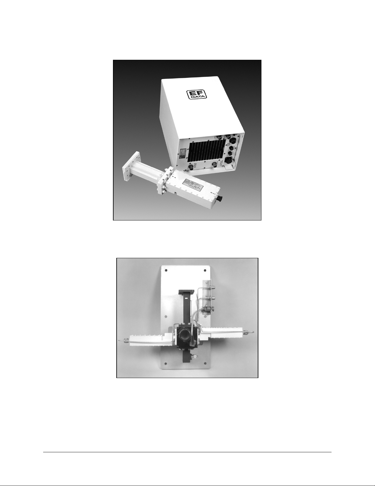
As a single thread system, the CST-5005 is comprised of the following assemblies
(Figure 1-1):
Chapter 1.
INTRODUCTION
1
• Outdoor enclosure assembly (RFT-505)
• Low Noise Amplifier (LNA)
As a redundant system, the CST-5005 is comprised of the following assemblies:
• Two outdoor enclosure assemblies (RFT-505s)
• Redundant LNA plate (Figure 1-2)
• RSU-503 (Figure 1-3)
For more information on the RSU-503, refer to the Comtech Comtech EFData RSU-503
Redundancy Switch Unit Installation and Operation Manual.
Refer to Figure 1-4 for a block diagram of the CST-5005.
The CST-5005 meets all requirements for operation on both private and regional
domestic C-band satellite networks.
Rev. 1 1–1
Page 12
Introduction CST-5005 C-Band Satellite Terminal
Figure 1-1. CST-5005 Single Thread System
Figure 1-2. Redundant LNA Plate
Note:
Pictured above are typical LNAs. Other LNAs are available, and can be ordered
from an Comtech EFData marketing representative.
1–2 Rev. 1
Page 13
CST-5005 C-Band Satellite Terminal Introduction
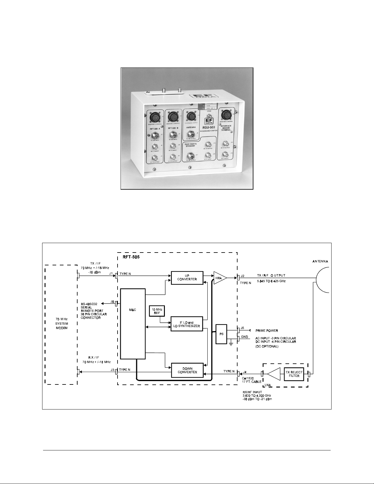
Figure 1-3. RSU-503
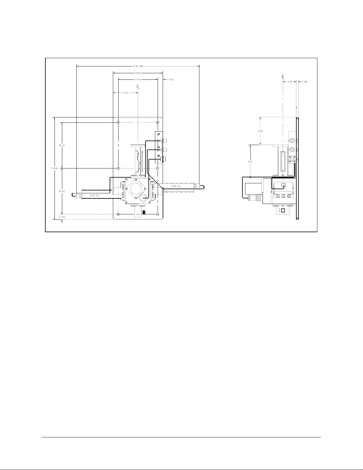
Figure 1-4. CST-5005 Block Diagram
Rev. 1 1–3
Page 14

Introduction CST-5005 C-Band Satellite Terminal
1.1.1 Applications
When used in conjunction with Comtech EFData modems, the CST-5005 is ideal for:
• Single digit carriers up to 2.048 Mbit/s
• Multiple carrier operation over a 36 MHz bandwidth
Because the CST-5005 has a 70 MHz IF, it can also be used for other analog and digital
applications.
Small-to-medium size earth stations are easily constructed and commissioned with the
CST-5005.
When used with a high-gain antenna, the CST-5005 can also be used as the Radio
Frequency (RF) electronics of a central hub in point-to-multipoint applications, as well
as serve as the terminal for the end points of the network.
1.1.2 Monitor and Control
An on-board microcomputer monitors and controls all operational parameters and system
status of the CST-5005. This powerful M&C system enables the user to locally or
remotely control functions such as:
Output power
•
Transmit/receive channel frequencies
•
The system also reports terminal configuration status, as well as fault status of all
CST-5005 components.
The CST-5005 can be initially configured using a connection of a common
ASCII/RS-232-C terminal connected to the serial port.
A simple command set allows total configuration control and retrieval of status
information.
If the indoor unit is a more sophisticated station M&C computer, the serial port can be
set to RS-485 for bus operation.
For more information on the M&C board, refer to Chapter 5.
1–4 Rev. 1
Page 15

CST-5005 C-Band Satellite Terminal Introduction
1.1.3 Low Noise Amplifier (LNA)
The feed assembly consists of an LNA and a wave guide transmit reject filter.
The transmit reject filter provides receive system protection from transmit energy fed
back through the antenna feed system.
The LNA standard noise temperature is 65°K, with optional upgrades down to 33°K,
depending upon gain over temperature (G/T) requirements.
1.1.4 Outdoor Enclosure
The RFT-505 is a weatherproof enclosure housing the following:
Solid State Power Amplifier (SSPA)
•
Up and down converters
•
M&C microprocessor
•
Power supply and cables which interface with an antenna subsystem
•
In the transmit (uplink) direction, the RFT-505 accepts a 70 MHz IF signal, and transmits
it in the 5.845 to 6.425 GHz frequency band.
In the receive (downlink) direction, the terminal accepts an RF signal in the 3.620 to
4.200 GHz band, and converts the signal to 70 MHz IF output.
Power levels range from +8 dBm (for driving an external TWT) to 10W, depending upon
Equivalent Isotropically Radiated Power (EIRP) requirements.
The up and down converters are dual conversion, with individual synthesizers for
independent transmit and receive transponder selection.
The microprocessor provides:
• Online loop monitoring
• Dynamic control functions
• Configuration control
• Fault/status monitoring
• Serial computer/terminal interface
Rev. 1 1–5
Page 16

Introduction CST-5005 C-Band Satellite Terminal
1.2 Options
1.2.1 Configurations
The CST-5005 can be ordered with various configurations, including:
• Output power levels
• Input power (AC/DC)
• LNA gain
• Redundant LNA mounting plates
• Custom logos
Contact an Comtech EFData marketing representative for more information.
1.2.2 Equipment
The following item is available:
• KP-10 hand-held keypad. The KP-10 provides portable, external access for
controlling the RFT. For information, refer to the Comtech EFData KP-10
External Keypad Installation and Operation Manual.
Contact an Comtech EFData marketing representative for more information.
1–6 Rev. 1
Page 17

CST-5005 C-Band Satellite Terminal Introduction
1.3 Specifications
Table 1-1 lists the specifications for the CST-5005, Table 1-2 lists the specifications for
the RFT-505, and Table 1-3 lists the specifications for the LNA.
Notes:
1. For specifications on the RSU-503, refer to the Comtech EFData RSU-503
Redundancy Switch Unit Installation and Operation Manual.
2. For more information pertaining to CST-5005 specifications, refer to Comtech
EFData Specification SP/4450.
Table 1-1. CST-5005 System Specifications
Prime Power 95 to 230 VAC, 47 to 63 Hz, or 48 VDC
Power Consumption:
+8 dBm output
5W output
10W
Size 15.1” H x 10.5” W x 8.9” D
Weight 39 lbs (typical)
Sealing Weatherproof
Ground Attach #10 AWG ground lug
Environmental:
Temperature
Humidity
Altitude
70W
125W
175W
17.1” H x 10.5” W x 8.9” D (10W system)
-40 to +55
-50 to +80
0 to 100% RH
0 to 15,000 ft operational
0 to 50,000 ft storage
C operational
°
C storage
°
Rev. 1 1–7
Page 18

Introduction CST-5005 C-Band Satellite Terminal
Table 1-2. RFT-505 Specifications
Transmit
Output Frequency (No inversion) 5.845 to 6.425 GHz
Input Frequency 70 MHz, ± 18 MHz (optional 140 MHz , ± 36 MHz)
Output Power:
at 1 dB compression +8 dBm
or 5W (+37 dBm)
or 10W (+40 dBm)
Third Order Intercept +18 dBm (for +8 dBm)
or +46 dBm (for 5W)
or +49 dBm (for 10W)
Nominal Small Signal Gain 26 dB (for +8 dBm)
or 68 dB (for 5W)
or +71 dBm (for 10W)
Gain Adjust Range (from nominal)
Gain Variation:
Over 36 MHz
Over 36 MHz, temperature, and aging
Noise Figure:
Maximum attenuation
Minimum attenuation
Group Delay, Total Variation in Passband 10 ns max
Synthesizer Step Size 125 kHz
Synthesizer Phase Noise -60 dBc/Hz at 100 Hz
Frequency Stability:
At shipment
Daily at 23
Annual at 23
C
°
C
°
Over temperature
After 30 minutes warm-up
Electrical adjustment
Isolation on Fault Shutdown -60 dBc
Spurious:
signal related
≤ 250 kHz carrier offset
> 250 kHz carrier offset
non-signal related
HPA Harmonics -50 dBc max
RF Output VSWR 1.35:1 at 50
RF Output Connector Type N female
IF Input VSWR 1.5:1 at 50
IF Input Connector Type N female
±
11 dB min
± 1 dB max
4
dB max variation
23 dB max
15 dB max
-70 dBc/Hz at 1 kHz
-80 dBc/Hz at 10 kHz
-90 dBc/Hz at 100 kHz
±
±
±
±
±
0.5 x 10
-8
1 x 10
-8
1 x 10
-7
1 x 10
1 x 10⁻⁸ (-40 to +55°C)
-8
1 x 10
-7
-35 dBc max
-50 dBc max
< -15 dBm/44 kHz max
Ω
Ω
1–8 Rev. 1
Page 19

CST-5005 C-Band Satellite Terminal Introduction
Receive
Input Frequency (No inversion) 3.620 to 4.2 GHz
Output Frequency 70 MHz, ± 18 MHz (optional 140 MHz , ± 36 MHz)
Output Power at 1 dB Comp +15 dBm
Gain Adjust Range (with LNA) 74 to 95 dB
Gain Variation (with LNA):
Over 36 MHz
Over 36 MHz, temperature, and aging
±
1.5 dB max
±
4 dB max
Noise Temperature (with LNA) LNA specification
Group Delay, Total Variation in Passband 10 ns max
Synthesizer Step Size 125 kHz
Synthesizer Phase Noise -60 dBc/Hz at 100 Hz
-70 dBc/Hz at 1 kHz
-80 dBc/Hz at 10 kHz
-90 dBc/Hz at 100 kHz
Frequency Stability:
At shipment
Daily at 23
Annual at 23
C
°
C
°
Over temperature
After 30 minutes warm-up
Electrical adjustment
±
±
±
±
±
0.5 x 10
-8
1 x 10
-8
1 x 10
-7
1 x 10
1 x 10⁻⁸ (-40 to +55°C)
-8
1 x 10
-7
Spurious In Band -60 dBc max
Image Rejection (all conversions) > 50 dB
Linearity Intermods < -35 dBc for two tones at -89 dBm at
+95 dB gain
RF Input VSWR (with LNA) 1.35:1 at 50
Ω
RF Input Connector Type N female
IF Output VSWR 1.5:1 at 50
Ω
IF Output Connector Type N female
Monitor and Control
Control Interface RS-232-C, RS-485
Control Functions SELECT PARITY
RF OUTPT LNA PWR
U/C FREQ LNA FLT
D/C FREQ CALIB. LNA
U/C ATTN REF ADJ
D/C ATTN XFLT ENABLE
PROGRAM RSW MODE
BAUD LOCK MODE
ADDRESS
Monitor Functions U/C TEMP
D/C TEMP
HPA TEMP
Fault Detect Functions 5V PWR HPA_FLT
D/C_FLT OSC_FLT
U/C_FLT SYN_LOCK_DET
2nd_SYN_LD XFE_FLT
RESET_FLT IFLO_LD
12V PWR UL_FLT
LNA_FLT DL_FLT
Rev. 1 1–9
Page 20

Introduction CST-5005 C-Band Satellite Terminal
Table 1-3. LNA Specifications
LNA Dimensions Refer to Figures 1-5 or 1-6
Frequency 3.620 to 4.200 GHz
Noise Temperature (with TRF) 65°K max (lower temperatures optional)
Gain 50 dB minimum, 54 dB nominal
Gain Flatness ± 1 dB/575 MHz
Gain vs. Temperature ± 3 dB max
1 dB Compression Point +12 dBm min
Third Order Intercept +22 dBm min
Group Delay:
Linear
Parabolic
Ripple
Input VSWR 1.25:1
Output VSWR 1.25:1
Input Connector CPR229G (hold pressure to .5PSIG)
Output Connector Type N
Spurious Below thermal noise/100 kHz
TRF Rejection 60 dB
± 0.01 ns/MHz max
0.001 ns/MHz
2
max
0.1 ns P-P
1–10 Rev. 1
Page 21

CST-5005 C-Band Satellite Terminal Introduction
Figure 1-5. Dimensions for a Single Thread LNA
Rev. 1 1–11
Page 22
Introduction CST-5005 C-Band Satellite Terminal
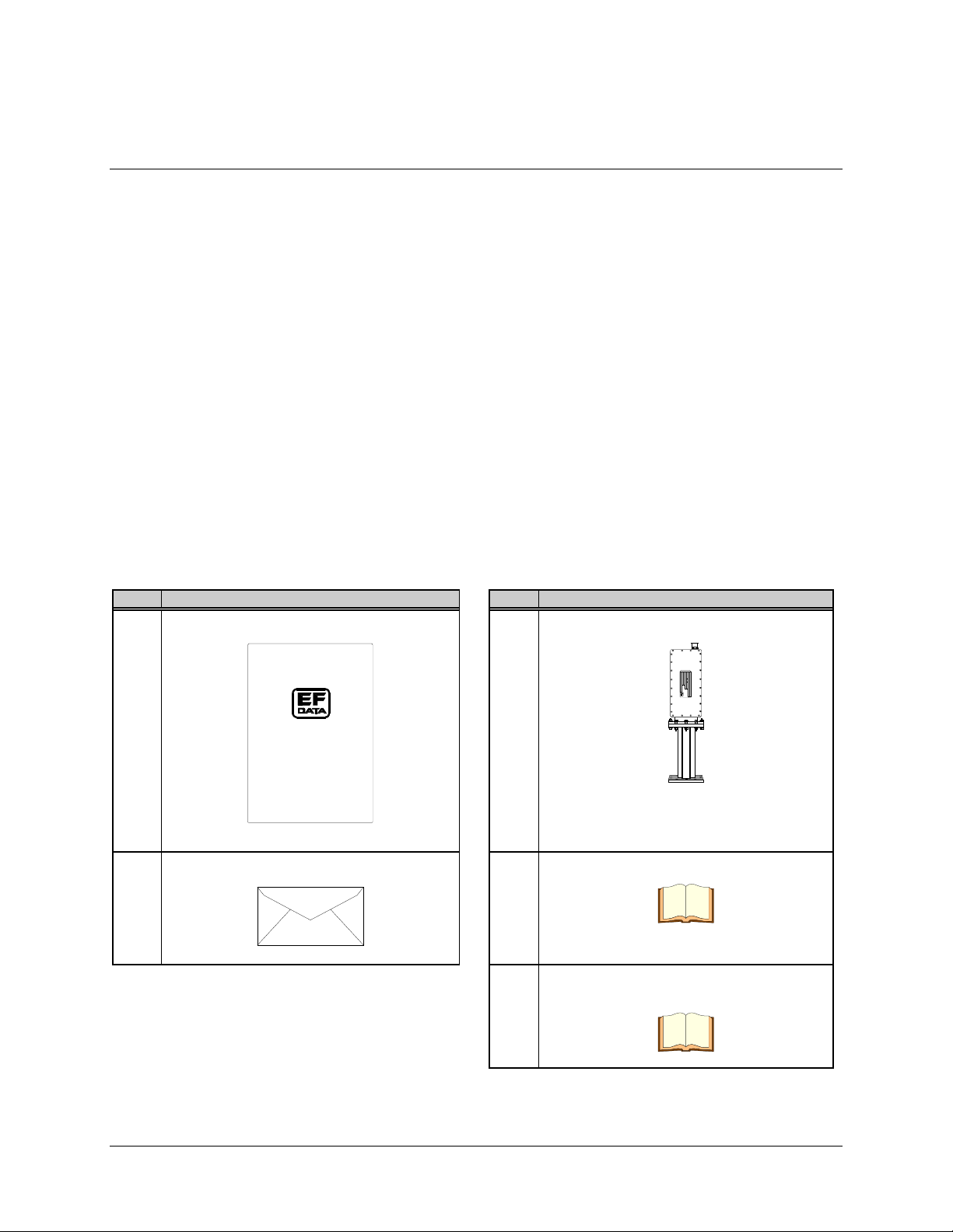
Figure 1-6. Dimensions for 1:1 Redundant LNA Plate
1–12 Rev. 1
Page 23

This chapter provides installation information for single thread systems, including:
For redundant systems, refer to Chapter 3.
2.1 Unpacking
Chapter 2.
SINGLE THREAD SYSTEM
INSTALLATION
2
• Unpacking and inspecting the parts
• Installing the RFT
• Installing the LNA
• External connections
The CST-5005 is packaged in preformed, reusable foam inside a cardboard carton.
Before unpacking the carton components, ensure that there is plenty of room around the
carton for workspace. A large table is recommended.
To remove the parts:
1. Cut the tape at the top of the carton where it is indicated OPEN THIS END.
2. Lift out the cardboard/foam spacer covering the unit.
3. Remove each part from the carton. Refer to Section 2.2.1 for a parts breakdown.
Because the RFT is heavy, assistance may be necessary to remove
the unit from the box.
CAUTION
Note:
Save the packing material for reshipment.
Rev. 1 2–1
Page 24
Single Thread System Installation CST-5005 C-Band Satellite Terminal
A
A
2.2 Inspecting the Equipment
1. Carefully check the equipment for damage incurred during shipment.
2. Carefully check the equipment against the packing list shipped with the
equipment to ensure that the shipment is complete. Refer to the following
paragraphs.
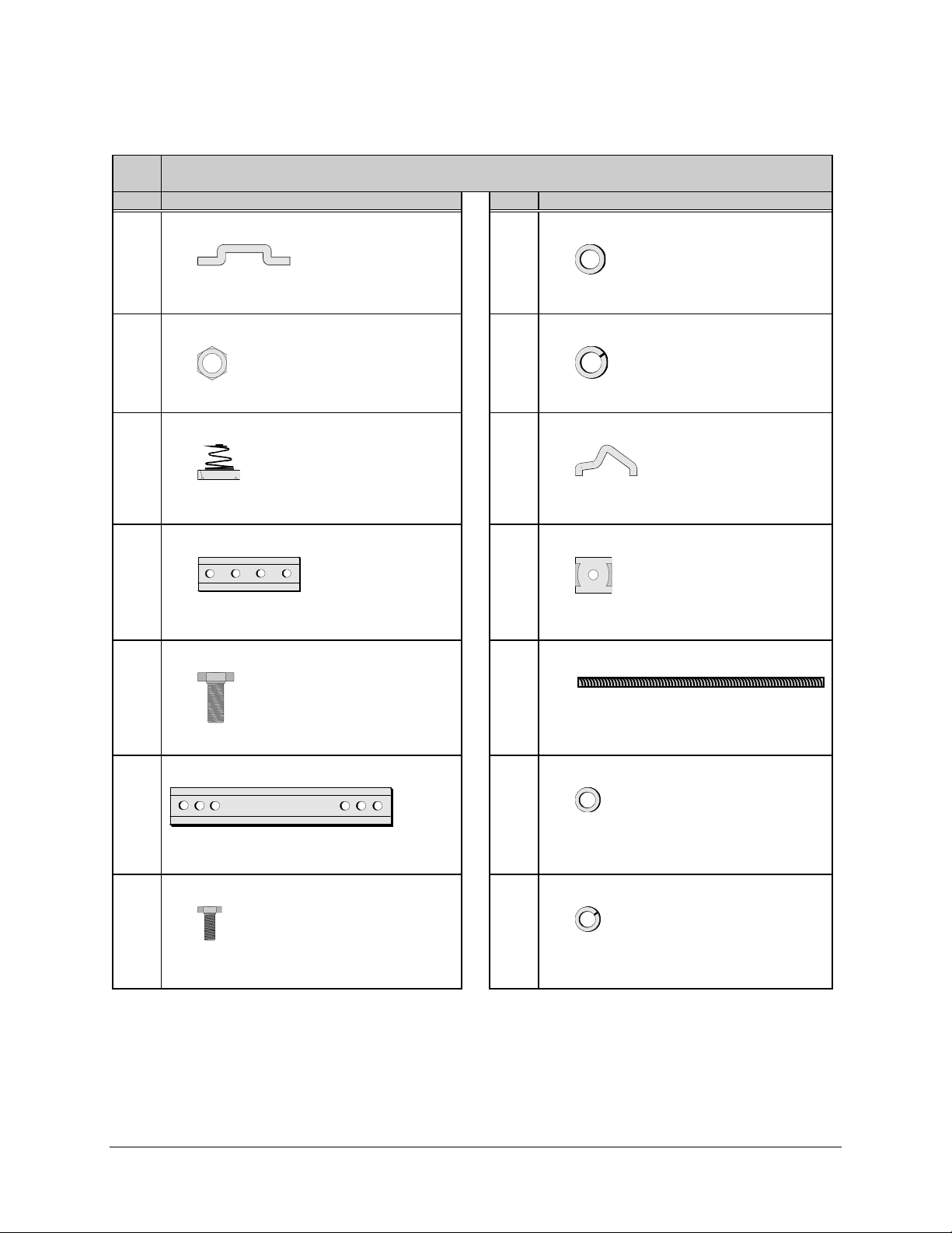
2.2.1 Included Parts
A typical single thread CST-5005 configuration contains the following components.
Notes:
1. Parts are not drawn to scale.
2. Because each system can be custom ordered, it is beyond the scope of this
manual to provide the unlimited configuration possibilities.
3. This chapter does not describe the installation procedures for amplifiers, high
performance LNAs, phase-locked LNBs, LNBs, and phase-locked block
converters.
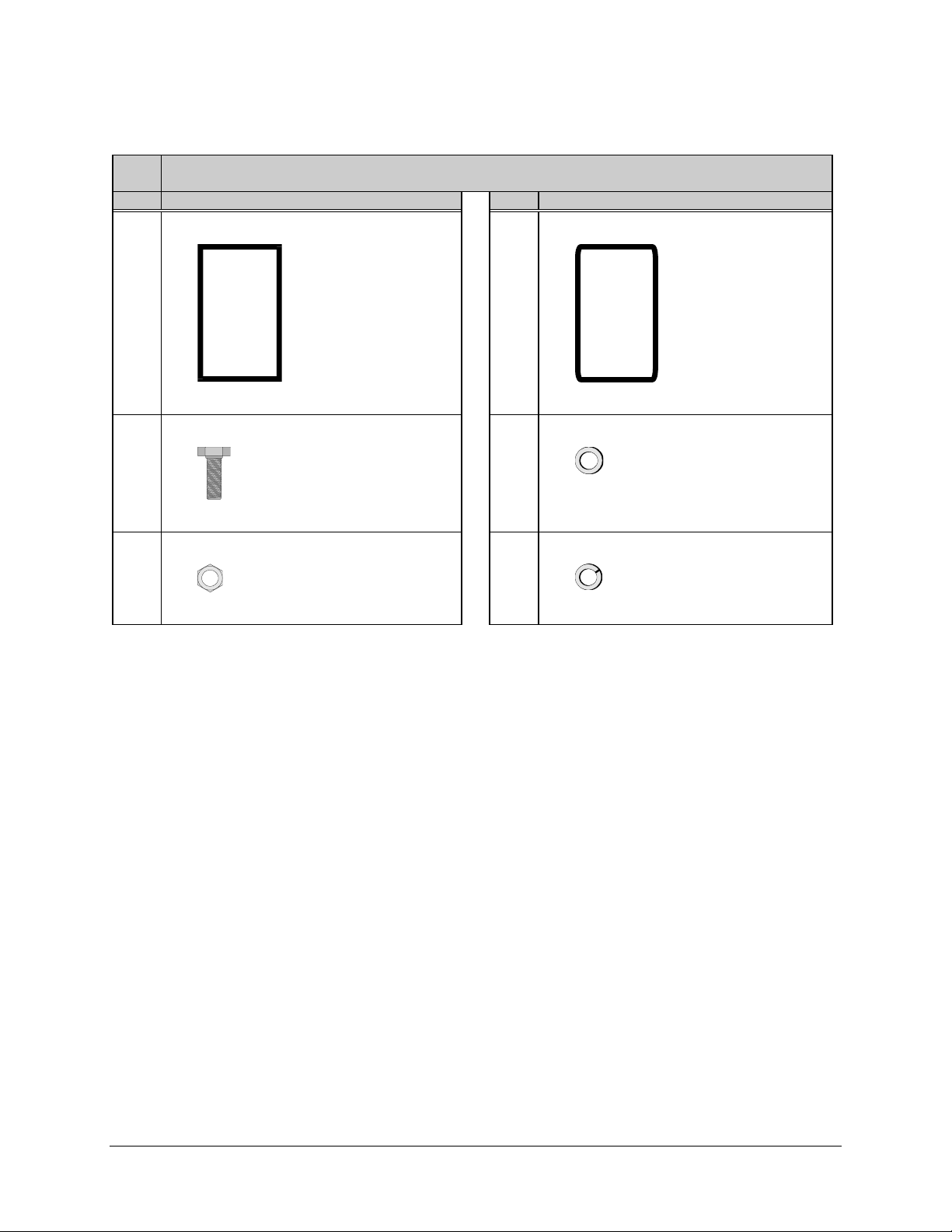
Qty. Description Qty. Description
1 RFT outdoor unit. 1 Feed assembly.
T
U
O
F
R
N
G
O
O
N
N
L
L
E
D
Y
R
P
O
E
C
M
S
N
M
E
E
T
U
E
Q
S
E
O
R
F
N
N
I
F
R
Note:
Pictured is a typical LNA. Other LNAs
are available, and can be ordered from an
EFData marketing representative.
1 Envelope containing the test data sheet. 1 CST-5005 installation and operation manual.
1 Monitor and Control Software for EFData
Satellite Terminals User’s Guide.
2–2 Rev. 1
Page 25
CST-5005 C-Band Satellite Terminal Single Thread System Installation
1 LNA connector kit (EFData Part # KT/2721), which includes:
Qty. Description Qty. Descr iption
1 Gasket — thick.
1 Gasket — thin.
EFData Part # 32P1040.
10 1/4-20 x 5/8” bolt.
EFData Part # 03P1079.
10 1/4-20 nut.
EFData Part # HW/1/4HEXNUT.
EFData Part # 32D1002.
20 1/4” flat washer.
EFData Part # O4P1022.
10 1/4” split lockwasher.
EFData Part # HW/1/4-SPLIT.
Rev. 1 2–3
Page 26
Single Thread System Installation CST-5005 C-Band Satellite Terminal
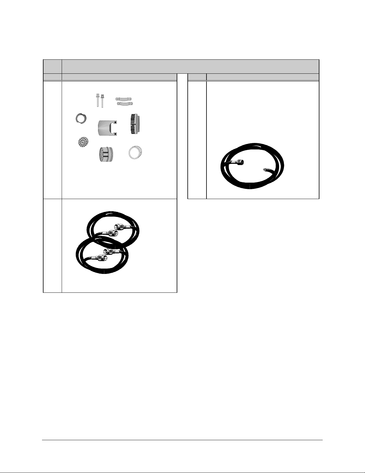
1 Kit KT/3272-x (where x = 1 for AC power, and 2 for DC power), which includes:
Qty. Description Qty. Descr iption
1 Connector kit.
EFData Part # CN/STPG26M01.
Used to connect customer’s cable to the RFT
26-pin J6 (REMOTE). For remote control and
status monitoring (by using M&C system
monitor software).
2 17’ Heliax cable.
1
Note:
Either the AC or DC cable is
provided, depending upon the product
ordering code.
Assembly, 15’ AC prime power cable.
EFData Part # PL/2754.
Assembly, 15’ DC prime power cable.
EFData Part # PL/4157.
EFData Part # CA/1530.
Used for RF input and RF output.
2–4 Rev. 1
Page 27

CST-5005 C-Band Satellite Terminal Single Thread System Installation
Note:
If an RFT for a spar mount is ordered, EFData will provide a spar mount kit
(KT/4061). Otherwise, the universal installation kit (KT/3576) will be provided.
1 Kit KT/4061, which includes:
Qty. Description Qty. Descr iption
2 Spar support bracket.
EFData Part # FP/3175.
Used for spar mount only.
8 1/4-20 x 5/8” bolt.
EFData Part # HW/1/4-20X5/8BT.
Used to attach 8” or 14” unistruts to RFT.
8 1/4” flat washer.
4 5/16-18 x 1” bolt.
EFData Part # HW/5/16-18X1BLT.
Used to attach spar support bracket to 8”
unistrut.
4 5/16” split lockwasher.
EFData Part # HW/5/16-SPLIT.
Used to attach spar support bracket to 8”
unistrut.
4 5/16” flat washer.
EFData Part # HW/1/4-FLT.
Used to attach 8” unistruts to RFT.
8 1/4” split lockwasher.
EFData Part # HW/1/4-SPLIT.
Used to attach 8” unistruts to RFT.
2 Unistrut — 8” long.
EFData Part # FP/3481.
Attaches directly to RFT.
EFData Part # HW/5/16-FLT.
Used to attach spar support bracket to 8”
unistrut.
4 5/16-18 spring nut.
EFData Part # HW/5/16-18SPNUT.
Used to attach spar support bracket to 8”
unistrut.
Rev. 1 2–5
Page 28

Single Thread System Installation CST-5005 C-Band Satellite Terminal
1 Kit KT/3576, which includes:
Qty. Description Qty. Descr iption
2 Spar support bracket.
EFData Part # FP/3175.
Used for spar mount only.
4 Unistrut — 14” long.
12 5/16-18 x 1” bolt.
EFData Part # HW/5/16-18X1BLT.
24 5/16” split lockwasher.
EFData Part # FP/3595.
Used for round and square pole mount only.
2 Unistrut — 8” long.
EFData Part # FP/3481.
Attaches directly to RFT.
8 1/4-20 x 5/8” bolt.
EFData Part # HW/1/4-20X5/8BT.
Used to attach 8” or 14” unistruts to RFT.
8 1/4” flat washer.
EFData Part # HW/1/4-FLT.
Used to attach 8” or 14” unistruts to RFT.
8 1/4” split lockwasher.
EFData Part # HW/5/16-SPLIT.
24 5/16” flat washer.
EFData Part # HW/5/16-FLT.
12 5/16-18 hex nut.
EFData Part # HW/5/16-18HEXNT.
16 5/16-18 spring nut.
EFData Part # HW/5/16-18SPNUT.
8 Flat fitting plate, 5/16”.
EFData Part # HW/1/4-SPLIT.
Used to attach 8” unistruts to RFT.
8 Pipe block.
EFData Part # HW/BLK-PIPE2-8.
Used for round pole mount only.
2–6 Rev. 1
EFData Part # HW/FIT-PLT-5/16.
4 Threaded rod, 5/16-18 x 14”.
EFData Part # HW/RD5/16-18X14.
Used for round and square pole mount only.
Page 29

CST-5005 C-Band Satellite Terminal Single Thread System Installation
2.3 RFT Installation
At the customer’s discretion, the RFT can be installed anywhere on or near the antenna.
The supplied hardware allows the installer a wide range of installation alternatives,
including:
• Vertical pole (e.g., mast) (either square or round). This is the most typical
installation.
• Within the hub of a large antenna.
• Spar (i.e., square bar) on the antenna structure.
EFData recommends that the RFT be mounted vertically, with the connections facing the
ground.
Rev. 1 2–7
Page 30
Single Thread System Installation CST-5005 C-Band Satellite Terminal
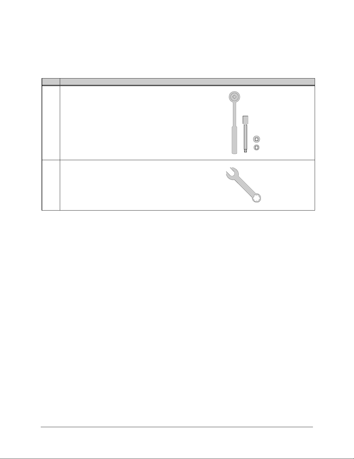
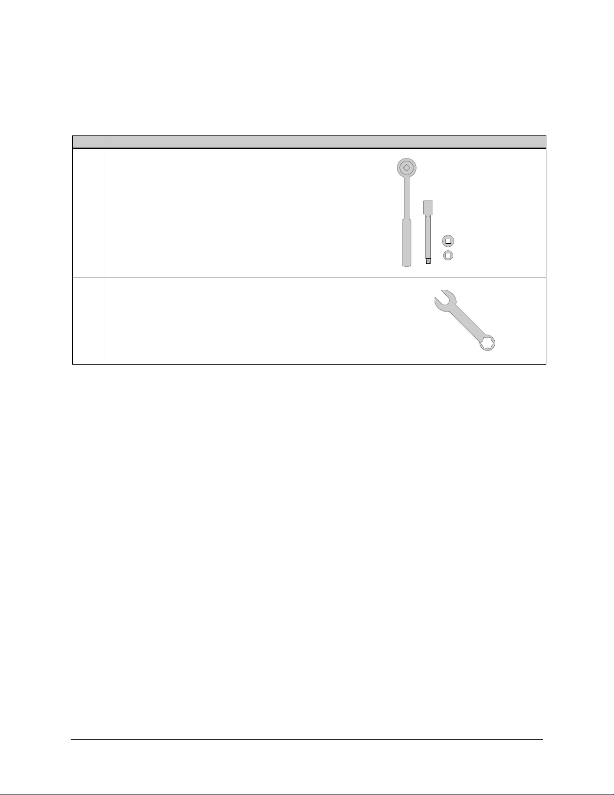
2.3.1 Tools Required
Qty. Description
1
3/8” drive ratchet.
1
3” x 3/8” drive extension.
1
7/16” x 3/8” drive socket. (Metric equivalent: 12mm, 6 pt.)
1
1/2” x 3/8” drive socket. (Metric equivalent: 13mm , 6 pt.)
1 1/2” combination wrench. (Metric equivalent: 13mm combination
wrench with a 6 pt. box end.)
2–8 Rev. 1
Page 31
CST-5005 C-Band Satellite Terminal Single Thread System Installation
2.3.2 Vertical Pole Installation
2.3.2.1 Round Pole
Note:
The following process is for a typical installation. Custom systems may be
ordered, and are beyond the scope of this manual.
To install the RFT to a round vertical pole:
1. Set the unit on its side, with the mounting holes facing up.
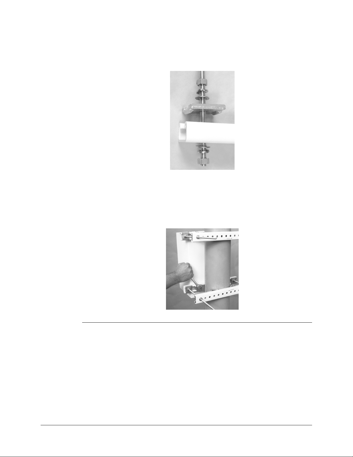
2. Install the two 14” unistruts as follows:
a. Position a 14” unistrut (with
the open side facing up)
over one set of the mounting
holes on the RFT.
b. Using four 1/4-20 bolts,
1/4” split lockwashers, and
1/4” flat washers, attach the
14” unistrut to the RFT.
Tighten the bolts firmly.
c. Repeat Steps 2.a. and 2.b.
for the second 14” unistrut.
Rev. 1 2–9
Page 32

Single Thread System Installation CST-5005 C-Band Satellite Terminal
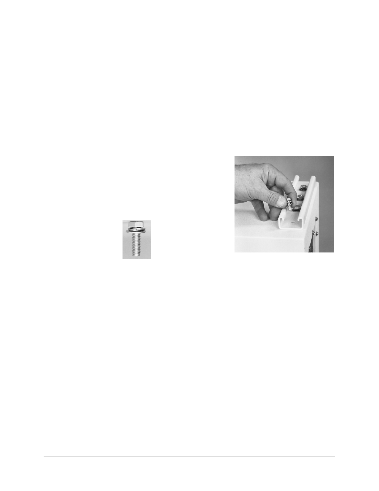
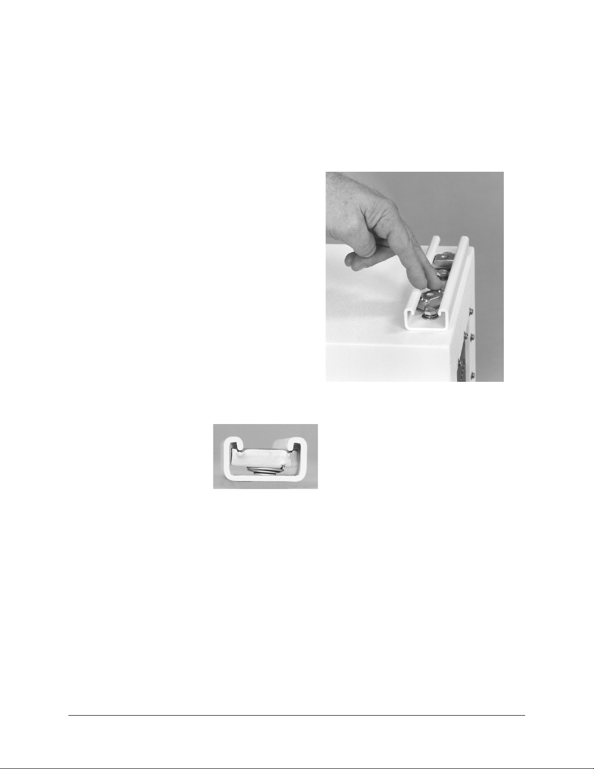
3. Install the pipe blocks as follows:
a. Install two spring nuts in each of four 14” unistruts (the two just mounted on
the RFT, and two additional).
Be sure to position the spring nuts in the unistruts wide enough apart so that
when the pipe blocks are installed, they will clear the pole when the unit is
lifted into place for installation.
b. Install each spring nut as follows:
(1) Place the spring nut in the unistrut channel, spring side down, with its
wide side parallel with the unistrut channel.
(2) Press down on the spring nut to compress the spring, and rotate the nut
90° (i.e., perpendicular to the unistrut).
(3) Release pressure on the spring nut.
(4) Repeat Steps 3.b.(1) through 3.b.(3) for each spring nut.
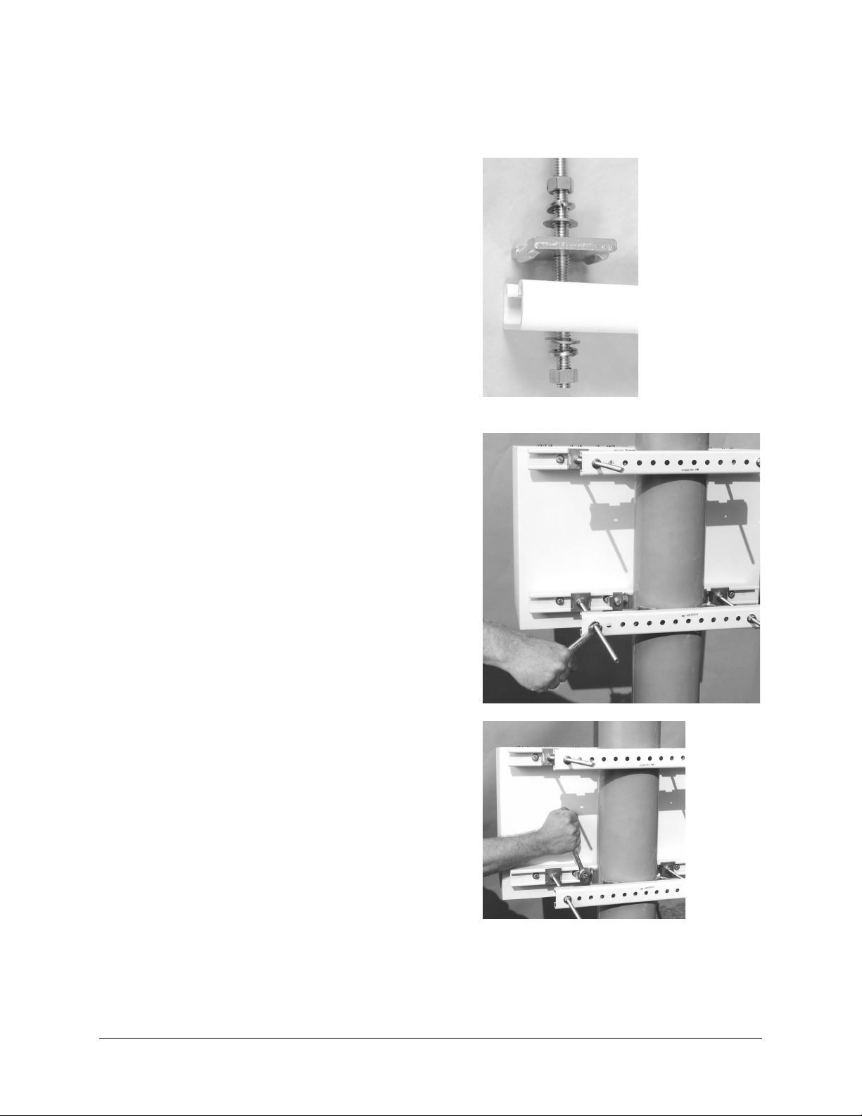
c. Using four 5/16-18 bolts, 5/16” split
lockwashers, and 5/16” flat washers,
loosely secure the pipe blocks to the
spring nuts.
Ensure the pipe blocks are installed
with the long angle facing inward,
toward the pipe, as illustrated.
DO NOT tighten the pipe block bolts
until after mounting the RFT on the
vertical pole. (See Step 5.e.)
2–10 Rev. 1
Page 33

CST-5005 C-Band Satellite Terminal Single Thread System Installation
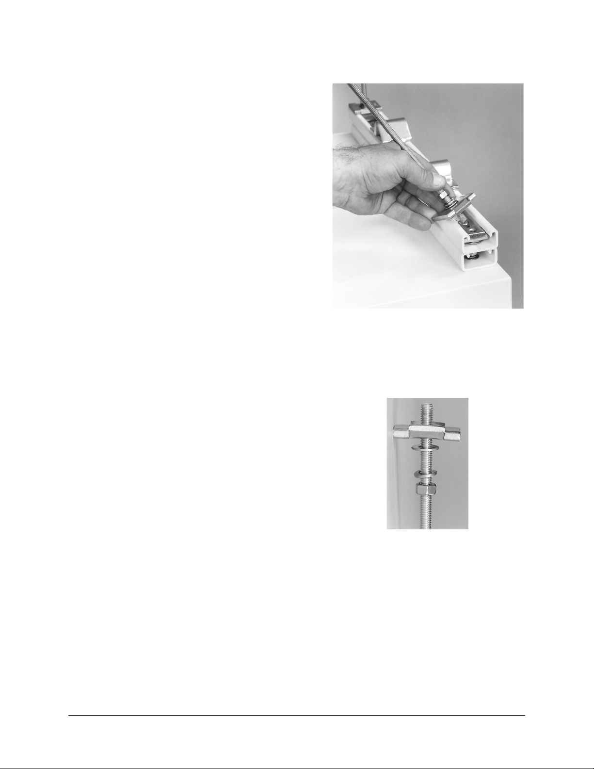
4. Install the threaded rods as follows:
a. Install two spring nuts in both 14”
unistruts mounted on the RFT.
Note:
Ensure the spring nuts are
positioned over the outer holes in the
14” unistruts, as illustrated.
b. To install each spring nut:
(1) Place the spring nut in the
unistrut channel, spring side
down, with its wide side parallel
with the unistrut channel.
(2) Press down on the spring nut to
compress the spring, and rotate
the nut 90° (i.e., perpendicular to
the unistrut).
(3) Release pressure on the spring nut.
(4) Repeat Steps 4.b.(1) through 4.b.(3) for each spring nut.
c. Thread a 5/16-18 nut approximately 1-1/2” onto each threaded rod. (This
will ensure that the threaded rods will extend beyond the spring nuts when
installed.)
d. Place a 5/16” split lockwasher, 5/16” flat washer, and flat fitting plate over
each threaded rod.
Rev. 1 2–11
Page 34

Single Thread System Installation CST-5005 C-Band Satellite Terminal
e. One threaded rod at a time, hold the
washers and plate in place on the rod,
and screw the rod into a spring nut, as
illustrated.
Notes:
1. Be sure to position the flanges
of the flat fitting plates in the
grooves of the unistruts.
2. Before tightening the nuts on
the threaded rods, ensure that
the end of each rod is screwed
in until it is flush with the
backside of the unistruts. This
ensures the rods are threaded
completely through the spring
nuts.
Tighten each nut firmly.
f. Thread a 5/16-18 nut about 2” onto the
end of each threaded rod.
g. Slip a 5/16” split lockwasher, 5/16” flat
washer, and flat fitting plate (in that
order) onto each threaded rod.
2–12 Rev. 1
Page 35

CST-5005 C-Band Satellite Terminal Single Thread System Installation
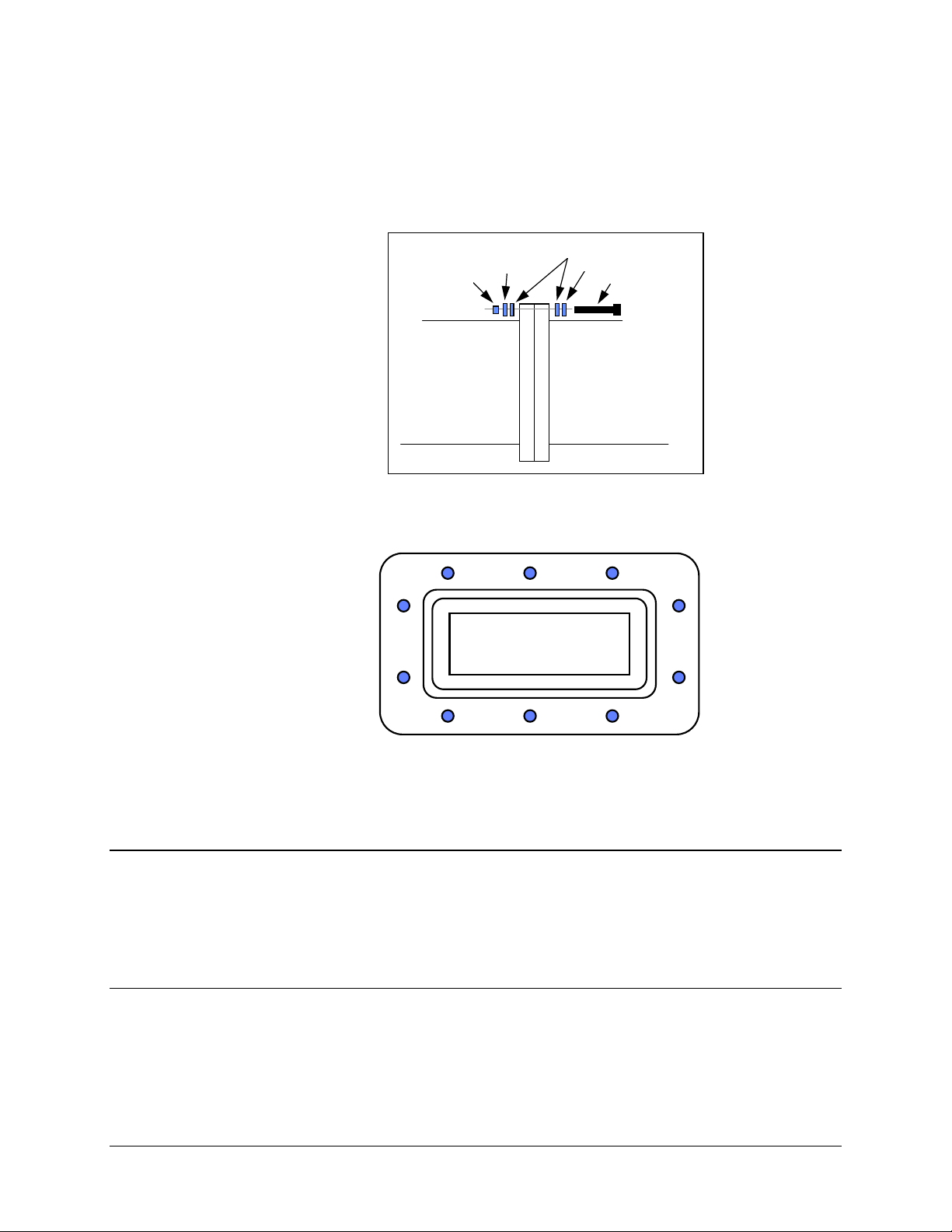
5. Mount the RFT as follows:
a. Lift the RFT into position on the vertical pole.
b. Slip a 14” unistrut over each of pair of threaded rods (upper and lower).
Note:
Install the 14” unistruts with the open face toward the pole as
illustrated below.
Rev. 1 2–13
Page 36
Single Thread System Installation CST-5005 C-Band Satellite Terminal
c. Install a 5/16” flat washer, 5/16” split lockwasher, and 5/16-18 nut on each
threaded rod.
d. Position the RFT as desired, and tighten the 5/16-18 nuts installed in
Step 5.c.
e. Slide the pipe blocks inward until they contact the vertical pole, then firmly
tighten the 5/16-18 bolts.
2.3.2.2 Square Pole
For square vertical pole installation, follow the steps in Section 2.3.2.1, with the
following exceptions:
• Do not perform Step 3.
• Do not perform Step 5.e.
2–14 Rev. 1
Page 37
CST-5005 C-Band Satellite Terminal Single Thread System Installation
2.3.3 Spar Installation
Note:
The following process is for a typical installation. Custom systems may be
ordered, and are beyond the scope of this manual.
To install the RFT to a spar:
1. Set the unit on its side, with the mounting holes facing up.
2. Install the 8” unistruts as follows:
a. Position an 8” unistrut (with the open
side facing up) over one set of the
mounting holes on the RFT.
b. Using four 1/4-20 bolts, 1/4” split
lockwashers, and 1/4” flat washers,
attach an 8” unistrut to the RFT.
Tighten the bolts firmly.
c. Repeat Steps 2.a. and 2.b. for the
second 8” unistrut.
Rev. 1 2–15
Page 38

Single Thread System Installation CST-5005 C-Band Satellite Terminal
3. Mount the RFT as follows:
a. Position a spring nut between the
inner and outer bolts on both sides
of each 8” unistrut, as illustrated.
b. Install each spring nut as follows:
(1) Place the spring nut in the
unistrut channel, spring side
down, with its wide side
parallel with the unistrut
channel.
(2) Press down on the spring nut
to compress the spring, and
rotate the nut 90° (i.e.,
perpendicular to the unistrut).
(3) Release pressure on the
spring nut.
(4) Repeat Steps 3.b.(1) through
3.b.(3) for each spring nut.
c. Lift the RFT into position.
d. Using four 5/16-18 bolts, 5/16”
split lockwashers, and 5/16” flat
washers, bolt the two spar support
brackets in place.
Tighten the bolts firmly.
2–16 Rev. 1
Page 39

CST-5005 C-Band Satellite Terminal Single Thread System Installation
2.4 LNA Installation
Refer to Section 2.2.1 for included parts.
To install a single LNA to an antenna:
1. Remove the protective cover from the antenna mount location (if installed).
2. Remove the plastic cover from the antenna end (RF IN) of the LNA.
3. Remove the plastic cover from the RF OUT end of the LNA.
After removing the protective cover(s), ensure that no foreign
material or moisture enters the antenna waveguide or LNA.
CAUTION
4. Install the appropriate gasket on the antenna end of the LNA:
a. If the LNA has a groove, and the antenna flange does not, the thin gasket
should be used.
b. If both the LNA and antenna flanges have grooves, the thick gasket should
be used.
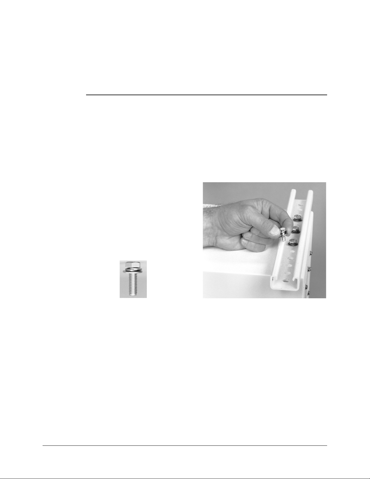
5. Position the LNA in place on the antenna, and install the 1/4-20 bolts, washers,
and nuts. Do not tighten at this time.
FLAT WASHER
SPLIT WASHER
BOLT
LNA
ANTENNA
NUT
SPLIT
WASHER
Rev. 1 2–17
Page 40
Single Thread System Installation CST-5005 C-Band Satellite Terminal
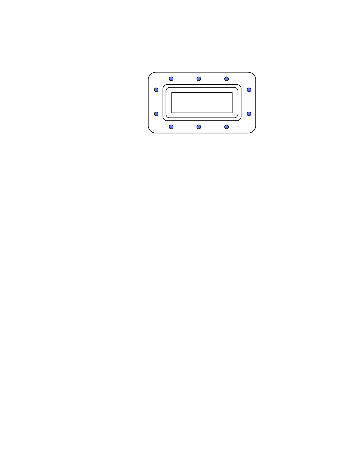
6. After all the bolts, washers, and nuts have been installed, tighten them according
to the following illustrated sequence.
5
7
4
1
2
3
10
89
6
2–18 Rev. 1
Page 41

CST-5005 C-Band Satellite Terminal Single Thread System Installation
2.5 External Connections
Connections between the RFT and other equipment are made through six connectors.
These connectors are listed in Table 2-1, and their locations are shown in Figure 2-1.
The use of each connector is described in the following paragraphs.
Table 2-1. Front Panel Connectors
Name Ref. Design. Connector Type Function
TX/IF IN J1 Type N TX IF INPUT (70 MHz)
TX/RF OUT J2 Type N 5.845 to 6.425 GHz Out
RX/IF OUT J3 Type N RX IF OUT (70 MHz)
RX/RF IN J4 Type N 3.620 to 4.200 GHz Input
PRIME PWR J5 Standard Prime Power Input
REMOTE J6 26-pin CIR Remote Interface
GND ERDE GND #10-32 Stud Chassis Ground
Figure 2-1. RFT-505 External Connections
Rev. 1 2–19
Page 42

Single Thread System Installation CST-5005 C-Band Satellite Terminal
2.5.1 TX/IF Input (J1)
The TX/IF input is from the indoor unit, and utilizes a type N connector.
The input impedance is 50
140 MHz,
± 36 MHz).
The typical power level is from -43 to -19 dBm, depending on the configuration and
application.
2.5.2 TX/RF Output (J2)
The TX/RF output has an output impedance of 50
The output frequency range is from 5.845 to 6.425 GHz. The output power level ranges
from +8 dBm to 10W (+40 dBm), depending on the power option ordered.
, and the frequency is 70 MHz, ± 18 MHz (optional
Ω
, and utilizes a type N connector
Ω
.
2–20 Rev. 1
Page 43

CST-5005 C-Band Satellite Terminal Single Thread System Installation
2.5.3 RX/IF Output (J3)
The RX/IF output goes to the indoor unit, and utilizes a type N connector.
The output impedance is 50
140 MHz,
± 36 MHz).
The 1 dB output compression point is +15 dBm minimum.
Nominal output power operation is +9 dBm (-6 dB from 1 dB compression) to -27 dBm,
depending on system gain requirements.
The down converter has 24 to 45 dB of gain, and is adjustable by the customer from 0 to
21 dB of attenuation.
The typical system gain includes a 50 dB LNA, making the total system gain 74 to
95 dB.
Note:
A 60 dB LNA is only used when there are extremely long cables from the LNA to
the down converter.
2.5.4 RX/RF Input (J4)
The RX/RF input comes from the LNA, and utilizes a type N connector.
The input impedance is 50
, and the frequency is 70 MHz, ± 18 MHz (optional
Ω
and the input frequency range is from 3.620 to 4.200 GHz.
Ω,
The input signal level ranges between -53 dBm and -30 dBm, depending on LNA and
antenna gain.
The input level should be set to give the required signal level at J3, the RX/IF Output
(refer to Section 2.5.3).
Rev. 1 2–21
Page 44

Single Thread System Installation CST-5005 C-Band Satellite Terminal
2.5.5 Prime Power (J5)
The AC power is supplied to the terminal by a 3-pin power connector.
Normal input voltage is 90 to 260 VAC, 47 to 63 Hz. Maximum power consumption is as
follows:
Maximum
Power Output
+8 dBm 70W
5W (+37 dBm) 125W
10W (+40 dBm) 175W
The AC pinout is as follows:
Pin # Name Function Wire Color
AHI Line Brown
B LO Neutral Blue
C GND Ground Green/Yellow
Power Consumption
A circular 4-pin power connector is used for the DC (48 VDC) option.
The DC pinout is as follows:
Pin # Name
A + INPUT
B CHASSIS GROUND
C - INPUT
DN/C
2–22 Rev. 1
Page 45

CST-5005 C-Band Satellite Terminal Single Thread System Installation
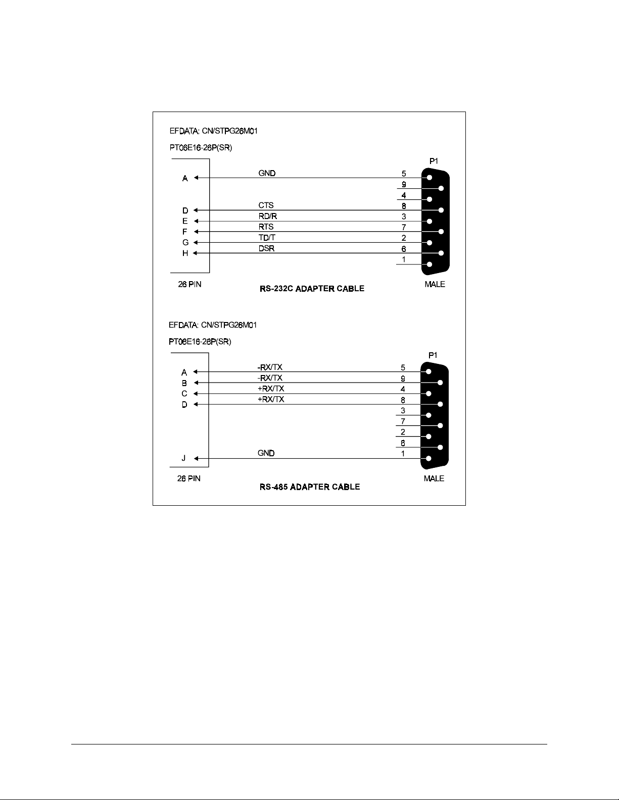
2.5.6 Serial Remote Control (J6)
The remote connector on the RFT is used to interface the M&C functions to a remote
location. This interface can be either RS-232-C or RS-485.
When using an RS-485 interface, the transmit and receive signals are able to
accommodate either type of remote equipment pinouts. As long as the polarities of the
remote equipment TX and RX signals are correct, this remote interface will be
completely compatible.
Refer to Table 2-2 for a list of pinouts for the J6 connector.
For standard RS-232-C or RS-485 applications, an adapter cable must be used to connect
the 26-pin connector (J6) to a standard 9-pin D.
Refer to Figure 2-2 for an illustration of the adapter cable with its pinouts.
Rev. 1 2–23
Page 46

Single Thread System Installation CST-5005 C-Band Satellite Terminal
Table 2-2. RFT Remote Control Connector, J6
Pin # Name Description
RS-232-C RS-485
A GND -RX/TX RX/TX Data
B -RX/TX RX/TX Data
C +RX/TX RX/TX Data
D CTS +RX/TX Clear to send
E RD/RX Receive data
F RTS Ready to send
G TD/TX Transmit Data
H DSR Data Set Ready
J GND Ground (green)
K LNA_PWR Output, 10V for powering LNA
L EXT_PWR Output voltage, 11V, to power RSU-503 and KP-10
M EXT TWT FLT Input, logic 0 or 5V, 5V = FLT, 0V = normal
N EXT IN_1 Input, logic 0 or 5V, spare
P SPARE N/C
R GND Ground (green)
S GND Ground, Signal
T SPARE N/C
U UL_NC Uplink fault relay, connects to uplink COM with fault
V UL_COM Uplink fault relay, COMMON
W UL_NO Uplink fault relay, opens with fault
X DL_NC Downlink fault relay, connects to downlink COM
with fault
Y DL_COM Downlink fault relay, COMMON
Z DL_NO Downlink fault relay, opens with fault
a LNA PWR RTN Return for LNA Power
b EXT IN_2 Input, 0 to 5V Logic
c SPARE N/C
(see Note 1)
(see Note 1)
(see Note 2)
(see Note 3)
(see Note 3)
(see Note 2)
Notes:
1. In RS-232-C mode, CTS is tied to RTS (and vice versa).
2. LNA can be powered from these pins instead of up through the RF cable.
3. 5V is a floating level.
2–24 Rev. 1
Page 47
CST-5005 C-Band Satellite Terminal Single Thread System Installation
Figure 2-2. Serial Adapter Cables
2.5.7 GND
A #10-32 stud is available on the rear for the purpose of connecting a common chassis
ground between all of the equipment.
Rev. 1 2–25
Page 48

Single Thread System Installation CST-5005 C-Band Satellite Terminal
This page is intentionally left blank.
2–26 Rev. 1
Page 49

Chapter 3.
REDUNDANT SYSTEM
INSTALLATION
3
This chapter provides installation information for redundant systems, including:
• Unpacking and inspecting the parts
• Installing the RFTs
• Installing the 1:1 redundant plate
• External connections
For RSU-503 installation information, refer to the EFData RSU-503 Redundancy Switch
Unit Installation and Operation Manual.
For single thread systems, refer to Chapter 2.
If the RFTs are to be mounted individually, refer to Chapter 2 for installation
information.
Rev. 1 3–1
Page 50

Redundant System Installation CST-5005 C-Band Satellite Terminal
3.1 Unpacking
The CST-5005 redundant system is shipped in two cartons (one RFT each) and one crate.
To remove the parts:
1. Cut the tape at the top of each carton where it is indicated OPEN THIS END.
2. Lift out the cardboard/foam spacer covering the units.
3. Remove the parts from the cartons. Refer to Section 3.2.1 for a parts breakdown.
Because the RFTs are heavy, assistance may be necessary to remove
the units from the boxes.
CAUTION
4. Remove the screws from the lid of the wooden crate, and remove the lid.
5. Unbolt the redundant LNA plate and remove it from the crate.
6. Remove the remainder of the parts from the crate. Refer to Section 3.2.1 for a
parts breakdown.
Note:
Save the packing material for reshipment.
3.2 Inspecting the Equipment
1. Carefully check the equipment for damage incurred during shipment.
2. Carefully check the equipment against the packing list shipped with the
equipment to ensure that the shipment is complete. Refer to the following
paragraphs.
3–2 Rev. 1
Page 51

CST-5005 C-Band Satellite Terminal Redundant System Installation
3.2.1 Included Parts
A typical redundant CST-5005 configuration contains the following components.
Notes:
1. Parts are not drawn to scale.
2. Because each system can be custom ordered, it is beyond the scope of this
manual to provide the unlimited configuration possibilities.
3. This chapter does not describe the installation procedures for amplifiers, high
performance LNAs, phase-locked LNBs, LNBs, or phase-locked block
converters.
Qty. Description Qty. Description
2 RFT outdoor unit. 1 Redundant LNA plate.
Note:
Pictured is a typical LNA plate. Other
LNA plates are available, and can be ordered
from an EFData marketing representative.
1 RSU-503. 1 CST-5005 installation and operation manual.
1 Envelope containing the test data sheet. 1 RSU-503 installation and operation manual.
1 Monitor and Control Software for EFData
Satellite Terminals User’s Guide.
Rev. 1 3–3
Page 52

Redundant System Installation CST-5005 C-Band Satellite Terminal
1 LNA connector kit (EFData Part # KT/2721), which includes:
Qty. Description Qty. Description
1 Gasket — thick.
1 Gasket — thin.
EFData Part # 32P1040.
10 1/4-20 x 5/8” bolt.
EFData Part # 03P1079.
10 1/4” split lockwasher.
EFData Part # HW/1/4-SPLIT.
EFData Part # 32D1002.
20 1/4” flat washer.
EFData Part # O4P1022.
10 1/4-20 nut.
EFData Part # HW/1/4HEXNUT.
3–4 Rev. 1
Page 53

CST-5005 C-Band Satellite Terminal Redundant System Installation
1 Kit KT/3107-x (where x = 5 for AC power, and 6 for DC power), which includes:
Qty. Description Qty. Description
3 Connector kit.
EFData Part # CN/STPG26M01.
Used to connect customer’s cable to the RFT
26-pin J6 (REMOTE). For remote control and
status monitoring (by using M&C system
monitor software).
3 17’ Heliax cable.
2
Note:
Either the AC or DC cable is provided,
depending upon the product ordering code.
Assembly, 15’ AC prime power cable.
EFData Part # PL/2754.
Assembly, 15’ DC prime power cable.
EFData Part # PL/4157.
2 4’ M&C Redundancy Assy.
EFData Part # CA/1530.
Used for RF input and RF output.
4
TNC to N, 50Ω, 4’ cable.
EFData Part # PL/5143.
IF Tx and Rx cables from RFT to RSU.
2 Cable, N-Male, LDF4-50A, 3’, Heliax C -band.
EFData Part # CA/3230-1.
Used for CST-5000 terminal system only.
EFData Part # PL/3003.
Used for communications from RFTs A and B
to RSU.
1 17’ Cable, RSU-503 to redundant LNA plate.
EFData Part # PL/3006.
Communications from RSU to redundant LNA
plate.
Rev. 1 3–5
Page 54
Redundant System Installation CST-5005 C-Band Satellite Terminal
2 Kit KT/3576, which includes:
Qty. Description Qty. Description
5 Spar support bracket.
58 5/16” flat washer.
EFData Part # FP/3175.
Used for spar mount only.
30 5/16-18 hex nut.
EFData Part # HW/5/16-18HEXNT.
38 5/16-18 spring nut.
EFData Part # HW/5/16-18SPNUT.
4 Unitstrut — 8” long.
EFData Part # FP/3481.
Attaches directly to RFTs.
28 5/16-18 x 1” bolt.
EFData Part # HW/5/16-18X1BLT.
2 Unistrut, modified, 20” long.
EFData Part # HW/5/16-FLT.
58 5/16” split lockwasher.
EFData Part # HW/5/16-SPLIT.
20 Pipe block.
EFData Part # HW/BLK-PIPE2-8.
Used for round pole mount only.
20 Flat fitting plate, 5/16”.
EFData Part # HW/FIT-PLT-5/16.
10 Threaded rod, 5/16-18 x 14”.
EFData Part # HW/RD5/16-18X14.
Used for round and square pole mount only.
19 1/4” flat washer.
EFData Part #FP/3482.
Used for round and square pole mount only.
19 1/4-20 x 5/8” bolt.
EFData Part # HW/1/4-20X5/8BT.
Used to attach short unistruts to RFTs.
3–6 Rev. 1
EFData Part # HW/1/4-FLT.
Used to attach short unistruts to RFT.
19 1/4” split lockwasher.
EFData Part # HW/1/4-SPLIT.
Used to attach short unistruts to RFT.
Page 55

CST-5005 C-Band Satellite Terminal Redundant System Installation
3.3 RFT Installation
At the customer’s discretion, the RFTs can be installed anywhere on or near the antenna.
The supplied hardware allows the installer a wide range of installation alternatives,
including:
• Vertical pole (e.g., mast) (either square or round). This is the most typical
installation.
• Within the hub of a large antenna.
• Spar (i.e., rectangular bar) on the antenna structure.
EFData recommends that the RFTs be mounted vertically, with the air inlets facing the
ground.
Rev. 1 3–7
Page 56
Redundant System Installation CST-5005 C-Band Satellite Terminal
3.3.1 Tools Required
Qty. Description
1
3/8” drive ratchet.
1
3” x 3/8” drive extension.
1
7/16” x 3/8” drive socket. (Metric equivalent: 12mm, 6 pt.)
1
1/2” x 3/8” drive socket. (Metric equivalent: 13mm , 6 pt.)
1 1/2” combination wrench. (Metric equivalent: 13mm combination
wrench with a 6 pt. box end.)
3–8 Rev. 1
Page 57

CST-5005 C-Band Satellite Terminal Redundant System Installation
3.3.2 Vertical Pole Installation
3.3.2.1 Round Pole
The following process is for a typical installation. Custom systems may be ordered, and
are beyond the scope of this manual.
To install the RFTs to a round vertical pole:
1. Set the units on their sides, with the mounting holes facing up.
2. Install the 8” unistruts as follows:
a. Position an 8” unistrut (with
the open side facing up) over
one set of the mounting holes
on the RFT.
b. Using four 1/4-20 bolts, 1/4”
split lockwashers, and 1/4” flat
washers, attach an 8” unistrut
to the RFT.
Tighten the bolts firmly.
c. Repeat Steps 2.a. and 2.b. for
each of the remaining 8”
unistruts (for a total of four).
Rev. 1 3–9
Page 58
Redundant System Installation CST-5005 C-Band Satellite Terminal
3. Install the 20” unistruts as follows:
Note:
The placement of the pipe blocks may interfere with the inner or center
unistrut attaching bolts. Be sure to determine the pipe block placement locations
before bolting the 20” unistruts in place. It may be necessary to eliminate the
center or inner 20” unistrut mounting spring nuts and bolts.
a. Insert a spring nut between
the unistrut mounting bolts
on both RFTs, as illustrated.
b. To install each spring nut:
(1) Place the spring nut in
the unistrut channel,
spring side down, with
its wide side parallel
with the unistrut
channel.
(2) Press down on the
spring nut to compress
the spring, and rotate
the nut 90° (i.e.,
perpendicular to the
unistrut).
(3) Release pressure on the spring nut.
(4) Repeat Steps 3.b.(1) through 3.b.(3) for each spring nut.
3–10 Rev. 1
Page 59

CST-5005 C-Band Satellite Terminal Redundant System Installation
c. With the RFTs side-by side,
position a 20” unistrut
(open side facing up) in
place over one pair of 8”
unistruts.
Ensure the long unistrut is
centered over the RFTs.
d. Using two or three 5/16-18
bolts, 5/16” split
lockwashers, and 5/16” flat
washers, attach the 20”
unistrut to the 8” unistruts.
Tighten the bolts firmly.
e. Attach the second 20” unistrut to the second set of 8” unistruts by repeating
Steps 3.a. through 3.d.
4. Install the pipe blocks as follows:
a. Install two spring nuts in each of the two 20” long unistruts and two 14” long
unistruts (centered in the unistruts, and wide enough apart so the pipe blocks
will clear the pole when the unit is installed).
b. Install each spring nut as follows:
(1) Place the spring nut in the unistrut channel, spring side down, with its
wide side parallel with the unistrut channel.
(2) Press down on the spring nut to compress the spring, and rotate the nut
90° (i.e., perpendicular to the unistrut).
Rev. 1 3–11
Page 60

Redundant System Installation CST-5005 C-Band Satellite Terminal
(3) Release pressure on the spring nut.
(4) Repeat Steps 4.b.(1) through 4.b.(3) for each spring nut.
c. Using eight 5/16-18 bolts, 5/16” split lockwashers, and 5/16” flat washers,
loosely secure the pipe blocks to the spring nuts.
Ensure the pipe blocks are installed with the long angle face inward, toward
the pipe, as illustrated.
DO NOT tighten the pipe block bolts until after mounting the RFTs on the
vertical pole. (See Step 6.e.)
5. Install the threaded rods as follows:
a. Install two spring nuts in both
20” unistruts mounted on the
RFTs.
b. Install each spring nut as
follows:
(1) Place the spring nut in
the unistrut channel,
spring side down, with
its wide side parallel
with the unistrut
channel.
3–12 Rev. 1
Page 61

CST-5005 C-Band Satellite Terminal Redundant System Installation
(2) Press down on the spring
nut to compress the
spring, and rotate the nut
90° (i.e., perpendicular
to the unistrut).
(3) Release pressure on the spring nut.
(4) Repeat Steps 5.b.(1) through 5.b.(3) for each spring nut.
c. Thread a 5/16-18 nut
approximately 1-1/2” onto
each threaded rod. (This will
ensure that the threaded rods
will extend beyond the spring
nuts when installed.)
d. Place a 5/16” split
lockwasher, 5/16” flat
washer, and flat fitting plate
over each threaded rod.
Rev. 1 3–13
Page 62
Redundant System Installation CST-5005 C-Band Satellite Terminal
e. One threaded rod at a time,
hold the washers and plate in
place on the threaded rod and
screw it into a spring nut, as
illustrated.
Notes:
1. Be sure to position
the flanges of the flat
fitting plates in the
grooves of the
unistruts.
2. Before tightening the
nuts on the threaded
rods, ensure that the
end of each rod is
screwed in until it
contacts the unistrut.
This ensures the rods
are threaded
completely through
the spring nuts.
Tighten each nut firmly.
f. Thread a 5/16-18 nut about 2”
onto the end of each threaded
rod.
g. Slip a 5/16” split lockwasher,
5/16” flat washer, and flat
fitting plate (in that order)
onto each threaded rod.
3–14 Rev. 1
Page 63
CST-5005 C-Band Satellite Terminal Redundant System Installation
6. Mount the RFTs as follows:
a. Lift the RFT into position on
the vertical pole.
b. Slip a 14” unistrut over each
of pair of threaded rods
(upper and lower).
Note:
Install the 14” unistruts
with the open face toward the
pole, as illustrated.
c. Install a 5/16” flat washer,
5/16” split lockwasher, and
5/16-18 nut on each threaded
rod.
d. Position the RFT, as desired,
and tighten the 5/16-18 nuts
installed in Step 6.c.
e. Slide the pipe blocks in until
they contact the vertical pole.
Then, firmly tighten the
5/16-18 bolts.
Rev. 1 3–15
Page 64

Redundant System Installation CST-5005 C-Band Satellite Terminal
3.3.2.2 Square Pole
For square vertical pole installation, follow the steps in Section 3.3.2.1, with the
following exceptions:
• Do not perform Step 4.
• Do not perform Step 6.e.
3.3.3 Spar Installation
Note:
The following process is for a typical installation. Custom kits may be ordered and
are beyond the scope of this manual.
To install the RFTs to a spar:
1. Set the units on their side, with the mounting holes facing up.
2. Install the 8” unistruts as follows:
a. Position an 8” unistrut (with the open
side facing up) over one set of the
mounting holes on an RFT.
b. Using four 1/4-20 bolts, 1/4” split
lockwashers, and 1/4” flat washers,
attach an 8” unistrut to the RFT.
Tighten the bolts firmly.
c. Repeat Steps 2.a. and 2.b. for the
remaining 8” unistruts (for a total of
four).
3–16 Rev. 1
Page 65

CST-5005 C-Band Satellite Terminal Redundant System Installation
3. Install the 20” unistruts as follows:
a. Position a spring nut between the 1/4-20 bolts in each 8” unistrut, as
illustrated below:
b. Install each spring nut as follows:
(1) Place the spring nut in the unistrut channel, spring side down, with its
wide side parallel with the unistrut channel.
(2) Press down on the spring nut to compress the spring, and rotate the nut
90° (i.e., perpendicular to the unistrut).
(3) Release pressure on the spring nut.
(4) Repeat Steps 3.b.(1) through 3.b.(3) for each spring nut.
c. With the RFTs side by side, position a 20” unistrut in place over one pair of
8” unistruts (open side up).
Rev. 1 3–17
Page 66

Redundant System Installation CST-5005 C-Band Satellite Terminal
d. Using four 5/16-18 bolts, 5/16” split lockwashers, and 5/16” flat washers,
bolt the 20” unistrut to the 8” unistruts.
e. Tighten the bolts firmly.
f. Repeat Steps 3.c. through 3.e. for the second 20” unistrut.
4. Mount the RFTs as follows:
a. Lift the RFTs into position.
b. Using four 5/16-18 bolts, 5/16”
split lockwashers, and 5/16” flat
washers, bolt the two spar support
brackets in place.
Tighten the bolts firmly.
3–18 Rev. 1
Page 67

CST-5005 C-Band Satellite Terminal Redundant System Installation
3.3.4 1:1 Redundant Plate Installation
A typical 1:1 redundant plate is shown below. Refer to Section 3.2.1 for included parts.
To install the 1:1 redundant plate:
1. Mount the 1:1 redundant plate to the antenna.
Note:
The type of mounting is determined by the brand of antenna on which the
equipment will be installed.
2. Remove the plastic cover from the RF IN connector of the redundant plate.
After removing the protective cover, ensure that no foreign material
or moisture enters the 1:1 redundant plate’s waveguide.
CAUTION
3. Install the appropriate gasket on the RF IN connector of the redundant plate:
a. If the LNA has a groove, and the antenna flange does not, the thin gasket
should be used.
b. If both the LNA and the antenna flange have grooves, the thick gasket should
be used.
Rev. 1 3–19
Page 68
Redundant System Installation CST-5005 C-Band Satellite Terminal
4. Position the antenna waveguide in place on the RF IN connector, and install the
1/4-20 bolts, 1/4” split lockwashers, 1/4” flat washers, and 1/4-20 nuts.
Do not tighten the bolts at this time.
FLAT WASHER
SPLIT WASHER
BOLT
LNA
ANTENNA
NUT
SPLIT
WASHER
5. After all the bolts, washers, and nuts have been installed, tighten them according
to the following illustrated sequence.
5
7
1
3
10
89
4
2
6
6. Remove the plastic covers from all the connectors, and attach the appropriate
cables.
3.4 RSU-503 Installation
Refer to the EFData RSU-503 Redundancy Switch Unit Installation and Operation
Manual.
3.5 External Connections
Refer to Section 2.5 for external connections information.
3–20 Rev. 1
Page 69

This chapter provides operation information for the RFT-505.
4.1 System Operation
There are two methods of operating the RFT-505:
• Connect a PC running DOS to the RS-232-C/485 remote control port, and run
the M&C system monitor software. This software is DOS-based and provides an
interface to the remote commands.
For more information on the M&C system monitor program, refer to the Monitor
and Control Software for EFData Satellite Terminals User’s Guide.
Chapter 4 .
OPERATION
4
• Connect the optional KP-10 hand-held keypad. For more information, refer to
the KP-10 External Keypad Installation and Operation Manual.
4.2 Remote Control
Refer to Appendix A.
Rev. 1 4–1
Page 70

Operation CST-5005 C-Band Satellite Terminal
This page is intentionally left blank.
4–2 Rev. 1
Page 71

THEORY OF OPERATION
This chapter provides the basic theory of operation for the Monitor and Control (M&C)
board, high stability oscillator, IFLO synthesizer, and the up and down converters.
5.1 Monitor and Control
The RFT-505 uses a sophisticated microcontroller module to perform the M&C
functions of the terminal. This board (refer to Figure 5-1) is located inside of the
RFT-505, on top of the other assemblies.
The M&C monitors the RFT-505 and provides configuration updates to other modules
within the terminal when necessary.
Chapter 5.
5
Terminal configuration parameters are maintained in EEPROM, which provides for total
recovery after a power-down situation.
Fault monitoring and status gathering are also provided.
All RFT-505 functions are accessible through the remote communications interface.
Note:
For more information on the M&C board, refer to Chapter 1.
Rev. 1 5–1
Page 72
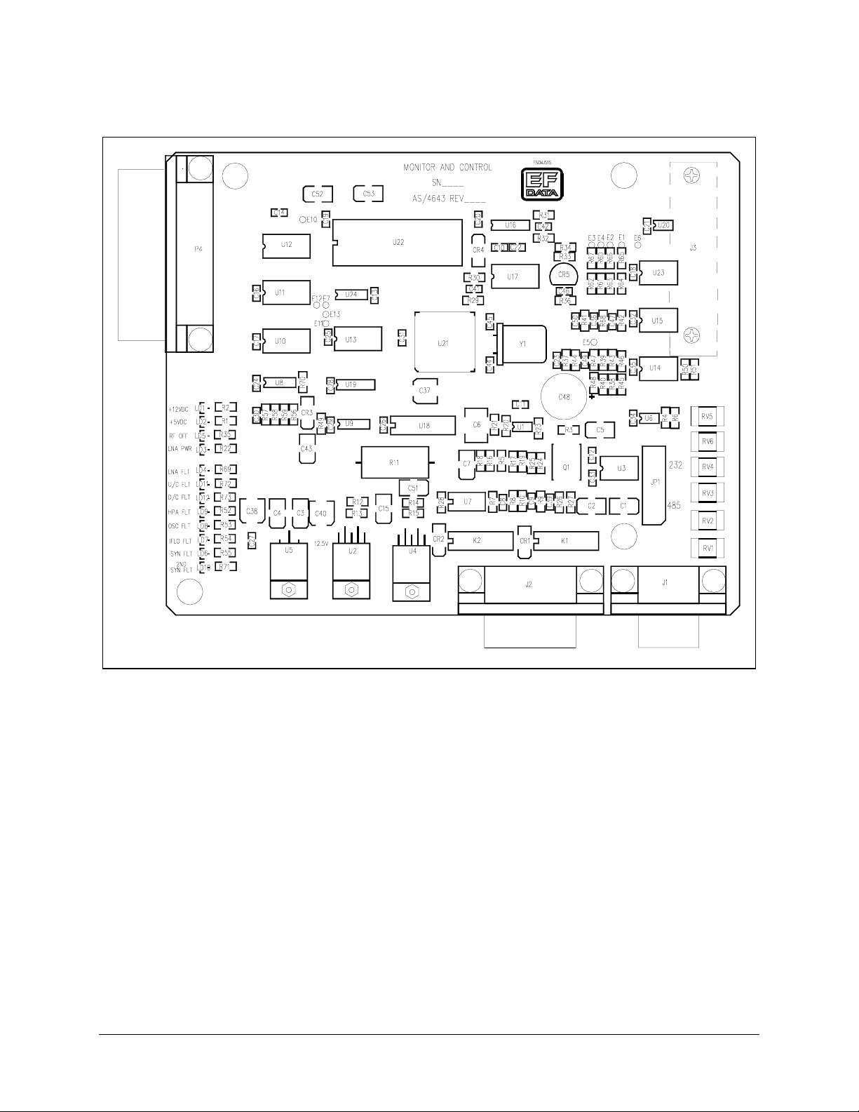
Theory of Operation CST-5005 C-Band Satellite Terminal
Figure 5-1. M&C Board
5–2 Rev. 1
Page 73
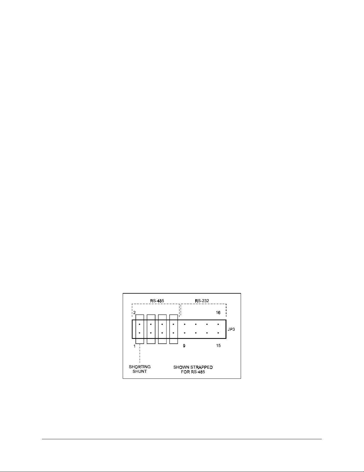
CST-5005 C-Band Satellite Terminal Theory of Operation
5.1.1 EEPROM Memory
EEPROM memory on the M&C module allows it to retain configuration information
without prime power for at least one year. If the terminal has been powered down, the
following power-up sequence will be carried out by the M&C microcontroller when
power is reapplied:
1. The microcontroller checks the EEPROM’s Random Access Memory (RAM) to
see if valid data has been retained. If valid data has been retained, the terminal is
reconfigured to the configuration maintained in EEPROM.
2. If EEPROM memory fails the valid data test, a default configuration from Read
Only Memory (ROM) is loaded into the system.
5.1.2 Remote Interface
The functions of the RFT-505 can be remotely controlled and monitored via an RS-485
or RS 232-C communications link. The M&C module must be hardware configured to
one of the two interfaces.
The RS-485 interface makes it possible to operate 255 terminals on a common
communications link.
The RS-232-C interface is used to communicate with a single terminal.
Refer to Figure 5-2 for the jumper placement at JP3.
Figure 5-2. M&C Jumper Placement at JP3
Rev. 1 5–3
Page 74

Theory of Operation CST-5005 C-Band Satellite Terminal
5.1.2.1 Remote Interface Specification
Refer to Appendix A.
5.1.3 Terminal Default Conditions
On initial power-up, the unit will default to the following parameters:
Parameter Default
Baud Rate 9600
Parity Ev en
Device Address 1
U/C Gain Max gain/or min attenuation
D/C Gain Max gain/or min attenuation
RF Output OFF
U/C Frequency 6135.00 MHz
D/C Frequency 3925.00 MHz
5.1.4 Theory of Operation
Refer to Figure 5-3 for a functional block diagram of the M&C.
The M&C board performs the following operations:
• Receives the desired frequency from either the remote RS-232-C/485 or KP-10
keypad, and after converting it to a synthesizer setting, stores it to the applicable
synthesizer output latch.
• Reads the thermistors located in the up converter, down converter, and highpower amplifier, and converts them to temperatures for display.
• Reads the characterization EEPROMs in the up converter, down converter, and
high-power amplifier, and calculates an Automatic Gain Control (AGC) voltage
based on frequency and temperature to linearize the respective module.
• Receives fault inputs from all modules, and presents them to the remote
RS-232-C/485 and the optional KP-10 keypad display.
• Performs an initial current sense on the LNA, and stores the reading in
EEPROM. Subsequent current sense readings are taken and compared to the
initial reading to determine a fault.
5–4 Rev. 1
Page 75

CST-5005 C-Band Satellite Terminal Theory of Operation
Figure 5-3. M&C Functional Block Diagram
Rev. 1 5–5
Page 76

Theory of Operation CST-5005 C-Band Satellite Terminal
5.1.5 M&C Board Connector Pinouts
5.1.5.1 RS-232-C/485 Remote Control (J1)
The remote interface is provided on a 9-pin male D connector. Screw locks are provided
for mechanical security of the mating connector. The remote connector is a Data Circuit
Terminating Equipment (DCE) interface.
Pin # RS-232-C RS-485 Description
1 GND GND Ground
2 TD/TX Transmit Data
3 RD/RX Receive Data
4 +RX/TX Plus Transmit or Receive
5 GND -RX/TX Negative Transmit or Receive
6 DSR Data Set Ready
7 RTS Ready to Send
8 CTS +RX/TX Clear to Send (RS-485 — Plus Transmit or
Receive)
9 -RX/TX Negative Transmit or Receive Data
Notes:
1. Clear to Send (CTS) is tied to Ready to Send (RTS) in RS-232
2. The pinout for Data Terminal Equipment (DTE) interface is provided for
RS-232
-
C.
5.1.5.2 Remote Relay Control, J2 DB15-Male
Pin # Name Description
1 EXT PWR Output voltage, 11V, 1A
9 LNA_PWR 10V to LN A
2 DL FLT NO Summary fault relay A
10 DL FLT COM Normal operation, common connects to NO
3 DL FLT NC Fault mode, common connects to NC
11 UL FLT NO Summary fault relay B
4 UL FLT COM Normal operation, common connects to NO
12 UL FLT NC Fault mode, common connects to NC
5 SPARE
13 EXT INPUT 2
6 SPARE
14 LNA_PWR_RTN Ground Return for LNA
7 EXT INPUT1 Input, logic 0 (normal) or 5V (fault)
15 EXT TWT FLT Input, logic 0 or 5V, used for TWT.FLT
8 GND Ground
-
C mode.
5–6 Rev. 1
Page 77

CST-5005 C-Band Satellite Terminal Theory of Operation
5.1.5.3 PS, Synthesizer, and D/C, P4 DB25-Male
Pin # Name Description
1 HPA 12V Input, 12.5V power from PS
14 HPA 12V Input, 12.5V power from PS
2 UC 12V Input, 12.5V power from PS
15 M&C 12V Input, 12.5V power from PS
3 SYN DATA Output CMOS level, Data
16 SYN CLOCK Output CMOS level, Clock
4 SYN EN1 Output CMOS level, Enable 1
17 SYN EN2 Output CMOS level, Enable 2
5 SYN EN3 Output CMOS level, Enable 3
18 IFLO LD Input, Open collector, floating = fault
6 SYN LD Input, Open collector, floating = fault
19 2ND SYN LD Input, Open collector, floating = fault
7 OSC FLT Input, Open collector, floating = fault
20 RNG_SW Output, CM O S lev el, range select
8 DC THERM Input, 5K thermistor tied to ground
21 SYN EN 4 Output, CMOS, Enable 4
9 DC GAIN CNTL Output, 0 to 5V
22 SDA Bidirectional, CMOS serial data
10 SCL Output, CMOS serial clock
23 LNA PWR Output, 11V pow er to the LN A coax
11 FREQ CNTL Output, 0 to 10V
24 M&C GND Ground
12 UC GND Ground
25 HPA GND Ground
13 HPA GND Ground
Rev. 1 5–7
Page 78

Theory of Operation CST-5005 C-Band Satellite Terminal
5.1.5.4 U/C and HPA, J3 DB25-Female
Pin # Name Description
1 UC 12V Output power to UC
14 HPA 12V Output power to high-power amplifier
2 HPA 12V Output power to high-pow er amplifier
15 N/C
3 HPA GAIN CNTL Output, 0 to 4V for gain control of high-power
amplifier
16 RF OFF Output, open collector, 0 = OFF
4N/C
17 N/C
5N/C
18 HPA FLT NO Input, Open = Fault
6 HPA FLT COM Output, ground connection to relay common
19 HPA FLT NC Input, Open = Normal
7N/C
20 HPA THERM Input, 10K thermistor to ground located in high-
power amplifier
8 UC THERM Input, 10K thermistor to ground located in UC
21 UC GAIN CNTL1 Output, 0 to 4 VDC for gain control of UC
9 UC GAIN CNTL2 Output, 0 to 4 VDC for gain control of UC
22 SDA Bidirectional, CMOS serial data
10 SCL Output, CMOS serial clock
23 SPARE
11 SPARE
24 SPARE
12 HPA GND Ground
25 HPA GND Ground
13 UC GND Ground
5–8 Rev. 1
Page 79
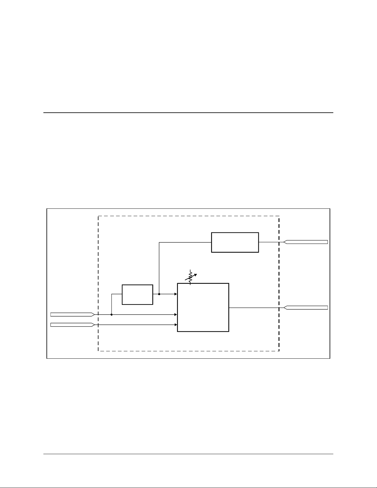
CST-5005 C-Band Satellite Terminal Theory of Operation
5.1.6 Test Points and LEDs
Refer to Section 6.1.
5.2 High Stability Oscillator
The high stability oscillator provides a low phase noise frequency-stable 10 MHz source
for the RF and IF local oscillator synthesizers.
The internal oven, which is provided for additional stability, operates directly from the
12V power source. The electronic control circuitry is buffered by an active filter.
Refer to Figure 5-4 for a block diagram of the High Stability Oscillator.
+12.5V
TUNING VOLTAGE
HIGH STABILITY OSCILLATOR
FILTER
0 to 10V ELECTRONIC TUNING
OSC
PWR
OVEN
PWR
12V
MECHANICAL
ADJUSTMENT
OVENIZED
HIGH STABILITY
OSCILLATOR
10 MHz
REGULATOR
Figure 5-4. High Stability Oscillator Block Diagram
OUTPUT
5V
REFERENCE
Rev. 1 5–9
Page 80

Theory of Operation CST-5005 C-Band Satellite Terminal
5.2.1 Specifications
Frequency 10 MHz
Frequency Stability
Output Level +7 dBm typical
Output Waveform Sinewave
Input Voltage 12.5V
Input Current
Warm-up 2.5 minutes to within 1 x 10⁻⁷ of final frequency at
Phase Noise (Maximum) 1Hz
Measurement bandwidth measured at
10 MHz:
10 Hz
100 Hz
1 KHz
10 KHz
Vibrational Sensitivity 1 x 10⁻⁹/g
Aging 5 x 10
Frequency Deviation (mechanical) To compensate for 10 years aging
Frequency Deviation (electrical)
-40 to +70°C
600 mA at turn-on, 250 mA after warm-up at +25°C
+25°C
-120 dBc
-150 dBc
-160 dBc
-165 dBc
-10
/day, 1 x 10⁻¹/year
± 2 x 10⁻⁶ minimum, 0 to 10 VDC
5–10 Rev. 1
Page 81

CST-5005 C-Band Satellite Terminal Theory of Operation
5.3 IF Local Oscillator
The IF local oscillator (IF LO) contains:
• Voltage Controlled Oscillator (VCO)
• Loop filter
• Divide-down chain
The lock detect status is sent to the M&C board, where it is monitored.
Refer to Figure 5-5 for a block diagram of the IF Local oscillator.
10 MHz REFERENCE
5.3.1 Specifications
Input 10 MHz Square wave, CMOS levels
Output 1112.5 MHz (2 each)
Connectors SMA
Output Impedance 50
Output Level +13 dBm
IF LO CAL OSCILLATOR
PHASE
DETECT
LOOP
FILTER
VCO
DIVIDE
DOWN
CHAIN
Figure 5-5. IF Local Oscillator Block Diagram
Ω
U/C
1112.5 MHz
SMA FEMALE
+13 dBm
D/C
1112.5 MHz
SMA FEMALE
+13 dBm
Rev. 1 5–11
Page 82

Theory of Operation CST-5005 C-Band Satellite Terminal
5.4 Synthesizer
The RFT-505 uses a single synthesizer.
The purpose of the synthesizer module is to convert the 10 MHz reference signal to a
variable frequency to perform the conversion.
5.4.1 Specifications
RF Inputs: 10 M H z references
Connector Type SMA
Impedance
Input level +7 dBm
RF Outputs: 4662.5 to 5242.5 MHz
Connector Type SMA
Impedance
Level +4 dBm
50Ω
50Ω
5.4.2 Theory of Operation
The synthesizer module multiplies the 10 MHz reference clock to a variable clock by use
of:
• VCOs
• Loop filters
• Phase detectors
• Variable divide-down chain
The divide-down chain is controlled by the M&C board.
Refer to Figure 5-6 for a block diagram of the synthesizer.
5–12 Rev. 1
Page 83

CST-5005 C-Band Satellite Terminal Theory of Operation
z
10 MHz REFERENCE
M&C BUS
SYNTHESIZER
DIVIDE
BY
Figure 5-6. Synthesizer Block Diagram
LOOP
FILTER
PHASE
DETECT
VCO
DIVIDE
BY N
DRO
PHASE
DETECT
DIVIDE
BY
M
RF SYNTH OUT
4662.5 to 5242.5 MH
+4 dBm
Rev. 1 5–13
Page 84
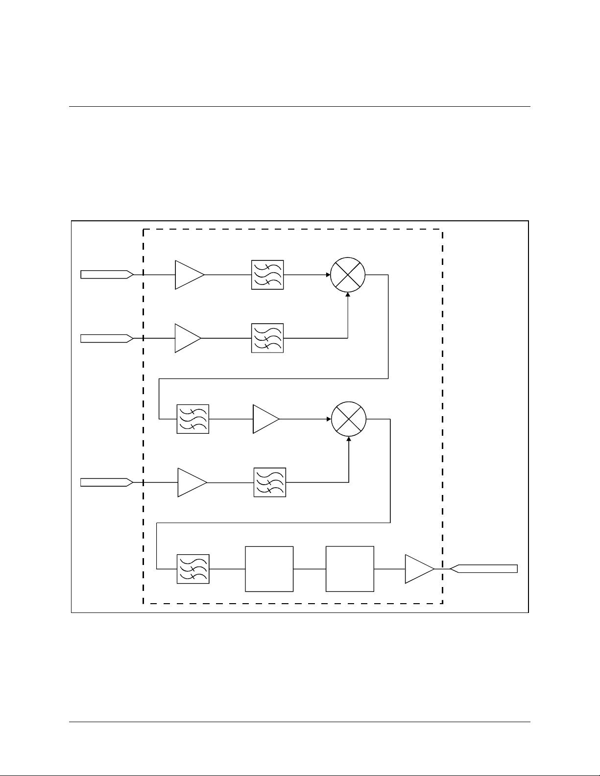
Theory of Operation CST-5005 C-Band Satellite Terminal
)
5.5 Down Converter
The function of the down converter is to convert the C-band signal from the LNA to a
70 MHz IF signal for use in the modem.
Refer to Figure 5-7 for a functional block diagram of the down converter.
DOWN CONVERTER
RF INPUT
3625 TO 4200 MHz
-36 TO -21 dBm
SMA FEMALE
FROM
SYNTHESIZER
LO INPUT
+4 dBm
SMA FEMALE
FROM IFLO
LO INPUT
1112.5 MHz
+13 dBm
SMA FEMALE
PHASE
EQUALIZER
ATTENUATOR
SMA FEMALE
2nd IF OUTPUT
70 MHz (+/-18 MHz
P=+11dBm
Figure 5-7. Down Converter Block Diagram
5–14 Rev. 1
Page 85

CST-5005 C-Band Satellite Terminal Theory of Operation
5.5.1 Specifications
Input Frequency 3620 to 4200 MHz
Input Connector SMA Female
Input Impedance
Input VSWR 1.5:1
Output Frequency 70 MHz (± 18 MHz )
Output Connector SMA Female
Output VSWR 1.3:1
1 dB Compression +17.5 dBm
Frequency 4662.5 to 5242.5 MHz, in 125 kHz steps
Level +8 dBm
Connector SMA Female
Return Loss 14 dB
Impedance
2nd IF Local Oscillator Input
Frequency 1112.5 MHz
Level +13 dBm
Connector SMA Female
Return Loss 14 dB
Impedance
50Ω
1st IF Synthesizer Input
50Ω
50Ω
5.5.2 Theory of Operation
The RFT-505 down converter utilizes a dual conversion process to convert from an input
RF frequency band of 3620 to 4200 MHz, to an output baseband 70 MHz IF signal.
The first conversion requires a down converter synthesizer frequency input to mix with
the RF input.
The M&C board controls the frequency selection of the synthesizer.
The synthesizer output frequency band is from 4662.5 to 5242.5 MHz, in 125 kHz steps.
The output of the first mixing process is at a frequency of 1042.5 MHz. The 1042.5 MHz
output is applied to the second mixer, which mixes with an IF Local Oscillator frequency
input at 1112.5 MHz.
The output of the second mixer is the desired baseband 70 MHz IF signal.
The M&C board interpolates the factory preset compensation data that is stored in an
EEPROM inside the down converter. This data allows the M&C board to command and
compensate the down converter’s output power, ensuring proper output power levels
over the entire frequency and temperature range.
Rev. 1 5–15
Page 86
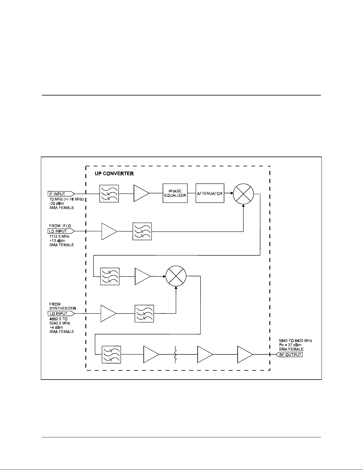
Theory of Operation CST-5005 C-Band Satellite Terminal
The M&C board also supplies the DC power for the LNA, which is subsequently
injected into the RF input connector.
5.6 Up Converter
The function of the up converter is to convert the 70 MHz IF signal from the indoor unit
modem to a C-band signal to be transmitted.
Refer to Figure 5-8 for a functional block diagram of the up converter.
Figure 5-8. 5W Up Converter Block Diagram
5–16 Rev. 1
Page 87

CST-5005 C-Band Satellite Terminal Theory of Operation
5.6.1 Specifications
Input Frequency 70 MHz (± 18 MH z)
Input Connector SMA Female
Input Impedance
Input VSWR 1.3:1
Output Frequency 5845 to 6425 MHz
Output Connector SMA Female
Output VSWR 1.5:1
1 dB Compression +37 dBm
1st RF Local Oscillator Input
Frequency 1112.5 MHz
Level +13 dBm
Connector SMA Female
Return Loss 10 dB
Impedance
Frequency 4662.5 to 5242.5 MHz, in 125 kHz steps
Level +4 dBm
Connector SMA Female
Return Loss 10 dB
Impedance 50
50Ω
50Ω
2nd RF Synthesizer Input
Ω
5.6.2 Theory of Operation
The RFT-505 up converter utilizes a dual conversion process to convert from a baseband
70 MHz IF signal to the output RF frequency band. The first conversion requires an IF
Local Oscillator frequency input at 1112.5 MHz from the synthesizer module.
The output of the first mixing process is at a frequency of 1182.5 MHz. The 1182.5 MHz
output is applied to the second mixer which mixes with the synthesizer frequency input.
The M&C board controls the frequency selection of the synthesizer and the U/C
attenuator.
The M&C board also interpolates the factory preset compensation data that is stored in
an EEPROM inside the up converter. This data allows the M&C board to command and
compensate the up converter’s output power, ensuring proper output power levels over
the entire frequency and temperature range.
The up converter synthesizer output frequency band is from 4662.5 to 5242.5 MHz, in
125 kHz steps.
The output of the second mixer is the desired RF frequency band of 5845 to 6425 MHz.
Rev. 1 5–17
Page 88

Theory of Operation CST-5005 C-Band Satellite Terminal
This page is intentionally left blank.
5–18 Rev. 1
Page 89

This chapter provides information on how to use test points and LEDs on the M&C
board for troubleshooting. In addition, this chapter provides guidelines for
troubleshooting faults.
6.1 Test Points and LEDs
Test points and LEDs are included on the M&C board for quick troubleshooting
references. LEDs are a visual reference. Test points are used when more troubleshooting
is required.
Refer to Table 6-1 for a list of LEDs and their functions. Refer to Table 6-2 for a list of
test points on the M&C board.
Chapter 6 .
MAINTENANCE
6
Table 6-1. M&C LEDs
Name Color Description
HPA FLT Red Illuminates when the high-power amplifier is faulted or turned off.
This fault will cause the transmitter to turn OFF.
IFLO FLT Red Illuminates when the IF local oscillator is out of lock. This fault will
cause the transmitter to turn OFF.
SYN FLT Red Illuminates when synthesizer 1 is out of lock. This fault will cause
the transmitter to turn OFF.
2ND SYN FLT Red Illuminates when synthesizer 2 (optional) is out of lock. This fault
will cause the transmitter to turn OFF.
LNA FLT Red Illuminates when the LNA is faulted, or LNA has not been
calibrated.
RF ON Yellow Illuminates when the high-power amplifier is turned ON.
12.5V Green Illuminates when 12.5V is applied to board.
5V Green Illuminates when 5V is applied to board.
OSC FLT Red Illuminates when reference oscillator fault is detected.
U/C FLT Red Illuminates when U/C is not connected, or is faulted.
Rev. 1 6–1
Page 90

Maintenance CST-5005 C-Band Satellite Terminal
Name Color Description
D/C FLT Red Illuminates when D/C is not connected, or is faulted.
LNA PWR Yellow Illuminates when LNA power is ON.
6.2 Fault Isolation
Once the terminal has been set up for operation, troubleshooting faults can be
accomplished by monitoring the terminal faults remotely, via the optional KP-10 external
keypad, or by removing the cover and observing the LEDs on the M&C board.
The following table should be used in isolating a problem and deciding the appropriate
action to be taken.
Refer to Figures 6-1 and 6-2 for the locations of the various modules mentioned in this
list.
Fault Possible Problem and Action
+5 VOLT +5V power supply fault. Indicates the +5V power supply on the M&C board is at
a high or a low voltage condition. Allowable level variation is ± 5%. Check for a
short on the +5V line, or faulty connection at P4 on the M&C board.
+12 VOLT +12V supply fault. Indicates the +12V power supply is at a high or low voltage
condition. Check for a short on the +12V line, or faulty connections between any
of the internal modules.
HPA High Power Amplifier fault. Verify that the RF output is programmed ON. Check
for a loose connection at J3. If acceptable, replace the U/C-HPA module. Once
the problem has been corrected, the transmitter must be turned back ON.
OSC Reference Oscillator fault. Check RF cable from reference oscillator module to
synthesizer/IFLO module. Check P4 on M&C and P13 on oscillator module. If
acceptable, replace the reference oscillator module.
D/C Down Converter fault. Indicates either faulty connection of module or missing
temperature/frequency compensation. Check P4 (at M&C) and J8 (at U/C). If
acceptable, replace D/C module.
U/C Up Converter fault. Indicates either faulty connection of module or missing
temperature/frequency compensation. Check J3 (at M&C) and P12 (at U/C). If
acceptable, replace U/C-HPA module.
SYNTH Synthesizer fault. Indicates that the synthesizer if out of lock. Check the RF
cable from reference oscillator module to the synthesizer/IFLO module. Check
J9, J8, and P7. If acceptable, replace the synthesizer/IFLO module.
IFLO IF Local Oscillator fault. Indicates the IFLO is out of lock. Check the connection
of the RF cable from reference oscillator module, J9, J8, and P7. If acceptable,
replace the synthesizer/IFLO module.
LNA Low Noise Amplifier fault. Check the RF cable from the LNA to J4 of the
RFT-505 terminal. If acceptable, replace the LNA.
6–2 Rev. 1
Page 91

CST-5005 C-Band Satellite Terminal Maintenance
Figure 6-1. RFT-505 Inside Front View
Rev. 1 6–3
Page 92

Maintenance CST-5005 C-Band Satellite Terminal
Figure 6-2. RFT-505 Inside Rear View
6–4 Rev. 1
Page 93

Appendix A.
REMOTE CONTROL OPERATION
A
This appendix describes the remote control operation of the RFT-505.
• Firmware number: FW/4644-1
• Software version: 1.0
A.1 General
Remote controls and status information are transferred via an RS- 485 (optional RS- 232-C)
serial communications link.
Commands and data are transferred on the remote control com munications link as
US ASCII-encoded character strings.
The remote communications link is operated in a half- duplex m ode.
Communications on the rem ote link are initiated by a rem o te controller or term inal. The
RFT-505 never transmits data on the link unless it is com manded to do so.
Rev. 1 A–1
Page 94

Remote Control Operation CST-5005 C-Band Satellite Terminal
A.2 Message Structure
The ASCII character form at used requires 11 bits/character:
• 1 start bit
• 7 information bits
• 1 parity bit
• 2 stop bits
or:
• 1 start bit
• 8 information bits
• no parity bit
• 2 stop bits
Messages on the remote link fall into the categories of commands and responses.
Commands are m essag es w hich are transm itted to an R FT- 505, w hile responses are
messages returned by an RFT-505 in response to a command.
The general message structure is as follows:
• Start Character
• Device Address
• Command/Response
• End of Message Character
A.2.1 Start Character
A single character precedes all messages transmitted on the remote link. This character
flags the start of a message. This character is:
“<”
•
“>”
•
for commands
for responses
A–2 Rev. 1
Page 95

CST-5005 C-Band Satellite Terminal Remote Control Operation
A.2.2 Device Address
The device address is the address of the controller which is designated to receive a
transmitted command, or w hich is responding to a com m and.
Valid device addresses are 1 to 3 characters long, and in the range of 1 to 255. Address 0 is
reserved as a global address which simultaneously addresses all dev ices on a g iv en
communications link. Devices do not acknowledge global commands.
Each RFT-505 which is connected to a common rem ote communications link must be
assigned its own unique address. Addresses are software selectable and must be in the
range of 1 to 255.
Note:
Global address “*” is reserved for the external keypad (i.e., the KP-10).
A.2.3 Command/Response
The command/response portion of the messag e contains a v ariable leng th character
sequence which conveys command and response data.
If a satellite modem receiv es a message addressed to it which does not match the
established protocol or cannot be implemented, a negativ e acknowledg ment message is sent
in response. This message is:
add/?ER1_parity error'cr''lf']
• >
(Error message for EV, OD, or NO parity errors.)
>add/?ER2_invalid parameter'cr''lf']
•
(Error message for a recognized command which cannot be implemented or has parameters
which are out of range.)
add/?ER3_unrecognizable command'cr''lf']
• >
(Error message for unrecognizable command or bad command syntax.)
>add/?ER4_converter in local mode'cr''lf ']
•
(Controller in lock mode. Must go to enable mode first.)
>add/?ER5_not supported by hardware'cr''lf']
•
(Command is a valid command. However, it is not supported by the current hardware
configuration.)
Note:
“add” is used to indicate a valid 1 to 3 character device address in the
range between 1 and 255.
Rev. 1 A–3
Page 96

Remote Control Operation CST-5005 C-Band Satellite Terminal
A.2.4 End Character
Each message is ended with a single character which sig n als the end of the m essag e:
“cr”
•
“]”
•
Note:
For the external keypad (i.e., the KP10), the end of message character is:
Carriage return character for commands
End bracket for responses
• “cr]” Carriage return and end bracket for commands
• “]” End bracket for responses
A–4 Rev. 1
Page 97

CST-5005 C-Band Satellite Terminal Remote Control Operation
A.3 Configuration Commands/Responses
Up
Converter
Freq Select
Down
Converter
Freq Select
RF Output Command:
Up
Converter
Attenuator
Command:
Response:
Status:
Response:
Command:
Response:
Status:
Response:
Response:
Status:
Response:
Command:
Response:
Status:
Response:
<add/UCF_nnnn.nnn'cr'
>add/UCF_nnnn.nnn'cr'
RF_OFF'cr''lf']
<add/UCF'cr'
>add/UCF_nnnn.nnn'cr''lf']
<add/DCF_nnnn.nnn'cr'
>add/DCF_nnnn.nnn'cr''lf']
<add/DCF'cr'
>add/DCF_nnnn.nnn'cr''lf']
<add/RF_xxx'cr'
>add/RF_xxx'cr''lf']
<add/RF_'cr'
>add/RF_xxx'cr''lf']
<add/UCA_nn.n'cr'
>add/UCA_nn.n'cr''lf']
<add/UCA_'cr'
>add/UCA_nn.n'cr''lf']
Where: nnnn.nnn = 5845.0 t o 6425.0 MHz, in 2.5 MHz or
125 kHz step size.
D/C frequency is 2225 MHz for single synthesizer system .
Where: nnnn.nnn = 3620.0 t o 4200.0 MHz, in 2.5 MHz steps or
125 kHz step size.
Status only for single synthesizer system .
Where: xxx = ON, WRM , or OFF.
The OFF command will keep the RF output turned of f under all
conditions.
The WRM comm and i s a conditional ON command instructing
the RF output to come on after the unit is warmed up and
meets stability requirement s.
The ON command is an override, i nstructing the output t o be
on and ignoring the warm start. The ON command cannot
override faults.
Where: nn.n = 0 to 25. 0 dB , in 0.5 dB steps.
Down
Converter
Attenuator
LNA
Calibration
LNA Fault
Enable
Reference
Freq Adjust
Lock Mode Command:
Command:
Response:
Status:
Response:
Command:
Response:
Command:
Response:
Status:
Response:
Command:
Response:
Status:
Response:
Response:
Status:
Response:
<add/DCA_nn.n'cr'
>add/DCA_nn.n'cr''lf']
<add/DCA_'cr'
>add/DCA_nn.n'cr''lf']
<add/CLNA_'cr'
>add/CLNA_'cr''lf']
<add/LFE_xxx'cr'
>add/LFE_xxx'cr''lf']
<add/LFE_'cr'
>add/LFE_xxx'cr''lf']
<add/RFJ_nnn'cr'
>add/RFJ_nnn'cr''lf']
<add/RFJ_'cr'
>add/RFJ_nnn'cr''lf']
<add/LM_xx'cr'
>add/LM_xx'cr''lf']
<add/LM_'cr'
>add/LM_xx'cr''lf']
Where: nn.n = 0 to 21. 0 dB , in 0.5 dB steps.
Performs a current windowing calibrat i on on the LNA.
This is only done once during the init i al i nstallation.
Where: xxx = ON (the default, enable monitor) or OFF.
Where: nnn = DAC set ting from 0 to 255.
Where: nnn = Current DAC s etting.
Where: xx = LK (lock) or EN (enable) (the def aul t).
Lock mode prevents the c urrent settings from being changed.
Rev. 1 A–5
Page 98

Remote Control Operation CST-5005 C-Band Satellite Terminal
External
Fault
Enable
LNA Power
Enable
Select
Preset
Config
Command:
Response:
Status:
Response:
Command:
Response:
Status:
Response:
Command:
Response:
Status:
Response:
<add/XFE_xxx'cr'
>add/XFE_xxx'cr''lf']
<add/XFE_'cr'
>add/XFE_xxx'cr''lf']
<add/LPE_xxx'cr'
>add/LPE_xxx'cr''lf']
<add/LPE_'cr'
>add/LPE_xxx'cr''lf']
<add/SEL_n'cr'
>add/SEL_n'cr''lf']
<add/SEL_'cr'
>add/SEL_'cr'
Where: xxx = ON (the default) or OFF.
Where: xxx = ON (the default, enable power) or OFF.
Where: n = 1, 2, or 3.
1
UCF_nnnn.nnn'cr' nnnn.nnn = 5845.0 to 6425.0 MHz.
DCF_nnnn.nnn nnnn.nnn = 3620.0 to 4200.0 MHz.
UCA_nn.n'cr' nn.n = 0.0 to 25.0 dB (UC Fine Adj).
DCA_nn.n'cr' nn.n = 0.0 to 21.0 dB (DC Fine Adj).
2
UCF_nnnn.nnn'cr' nnnn.nnn = 5845.0 to 6425.0 MHz.
DCF_nnnn.nnn nnnn.nnn = 3620.0 to 4200.0 MHz.
UCA_nn'cr' nn.n = 0.0 to 25.0 dB (UC Fine Adj).
DCA_nn n'cr' nn.n = 0.0 to 21.0 dB (DC Fine Adj).
3
UCF_nnnn.nnn'cr' nnnn.nnn = 5845.0 to 6425.0 MHz.
DCF_nnnn.nnn nnnn.nnn = 3620.0 to 4200.0 MHz.
UCA_nn.n'cr' nn.n = 0.0 to 25.0 dB (UC Fine Adj).
DCA_nn.n'cr''lf'] nn.n = 0.0 to 21.0 dB (DC Fine Adj).
Redundant
Switch
Mode
Program
Preset
Config
Command:
Response:
Status:
Response:
Command:
Response:
Status:
Response:
<add/RSW_xxxxx'cr'
>add/RSW_xxxxx'cr''lf']
<add/RSW_'cr'
>add/RSW_xxxxx'cr''lf']
<add/PGM_n'cr'
>add/PGM_n'cr''lf']
<add/PGM_'cr'
>add/PGM_'cr'
Allows the user to select any one of three 'PreSet'
configurations. The users must first program (store) a
configuration using the PGM_n command defined below. This
command used without the P reset number (n) will provide the
current programming of each of the three Presets.
Where: xxxxx = INDEP (the de faul t) or DEP.
Note: For use in redundant system only with RSU-503 switch.
(INDEP TX and RX switch independently on fault to backup
terminal. DEP switches both TX and RX on fault to backup
terminal.)
Where: n = 1, 2, or 3.
1
xxxxxxxxxx'cr' xxxxxxxxxx = 'Programmed ' or ' None'.
2
xxxxxxxxxx'cr'
3
xxxxxxxxxx'cr''lf']
Allows the user to store (program) the current frequency and
attentuator settings as one of three 'PreSet' sel ections.
A–6 Rev. 1
Page 99

CST-5005 C-Band Satellite Terminal Remote Control Operation
Clear
Program
Preset
Config
RS-232
Address
Select
RS-232
Baud Rate
Select
RS-232
Parity
Select
Command:
Response:
Status:
Response:
Command:
Response:
Status:
Response:
Command:
Response:
Status:
Response:
Command:
Response:
Status:
Response:
<add/CPGM_n'cr'
>add/CPGM_n'cr''lf']
<add/CPGM_'cr'
>add/CPGM_'cr'
<add/AS_xxx'cr'
>add/AS_xxx'cr''lf']
<add/AS_'cr'
>add/AS_xxx'cr''lf']
<add/BR_xxxxx'cr'
>add/BR_xxxxx'cr''lf']
<add/BR_'cr'
>add/BR_xxxxx'cr''lf']
<add/PS_xx'cr'
>add/PS_xx'cr''lf']
<add/PS_'cr'
>add/PS_xx'cr''lf']
Where: n = 1, 2, or 3.
1
xxxxxxxxxx'cr' xxxxxxxxxx = 'Programmed ' or ' None'.
2
xxxxxxxxxx'cr'
3
xxxxxxxxxx'cr''lf']
Allows the user to clear (unprogram ) the frequency and
attentuator setting f or one of three 'PreSet' selec tions.
Where:
add = current address.
xxx = new address, 1 to 255. Default address = 1.
Where: xxxxx = 300 to 19200, in standard set tings of 300, 600,
1200, 2400, 4800, 9600, and 19200. Default = 9600.
Where: xx = OD (odd), EV (even, the default), or
NO (none - 8 bit).
Rev. 1 A–7
Page 100

Remote Control Operation CST-5005 C-Band Satellite Terminal
A.4 Status Commands/Responses
Config Status Command:
Response:
Fault Status Com mand:
Response:
<add/OS_'cr'
>add/OS_'cr'
UCF_nnnn.nnn'cr'
DCF_nnnn.nnn'cr'
RF_xxx'cr'
DCA_nn.n'cr'
UCA_nn.n'cr'
SEL_n'cr''lf']
<add/FS_'cr'
>add/FS_'cr'
RST_xxx'cr'
UL_xxx'cr'
DL_xxx'cr'
PS5_xxx'cr'
P12_xxx'cr'
HPA_xxx'cr'
LNA_xxx'cr'
SYN_xxx'cr'
ILD_xxx'cr'
OSC_xxx'cr'
UCM_xxx'cr'
DCM_xxx'cr'
SL2_xxx'cr''If'] See Note
nnnn.nnn = 5845.0 to 6425.0 MHz.
nnnn.nnn = 3620.0 to 4200.0 MHz.
xxx = ON, WRM , or O FF.
nn.n = 0.0 to 21.0 dB. DC Fine Adj.
nn.n = 0.0 to 25.0 dB. UC Fine Adj.
n = 1, 2, 3, or None.
The command returns a block of data to be returned by the
addressed RFT-505.
The block of data reflect s the current configuration status.
xxx = OK o r FLT. Unit experienced a re start.
xxx = OK o r FLT. Uplink fault.
xxx = OK o r FLT. Downlink f ault.
xxx = OK o r FLT. +5V p ower supply.
xxx = OK o r FLT. +12V power supply.
xxx = OK o r FLT. Power amp fault.
xxx = OK o r FLT. LNA fault.
xxx = OK o r FLT. Synt hesizer1 L0 Lock Detect.
xxx = OK o r FLT. IF LO Lock Det ect.
xxx = OK o r FLT. 10 MHz REF O SC.
xxx = OK o r FLT. UC Module fault.
xxx = OK o r FLT. UC Module fault.
xxx = OK, FLT, or NA. Synt hesizer2 L0 Lock Detect.
This command returns a block of data reflec t i ng the current
and logged faults. Logged faults will be reset when receiving
this command, while current faults can be read on the second
request.
Note: Valid only in dual synthesizer systems, else N/A.
Summary
Fault Status
Maintenance
Status
Equipment
Type Status
Command:
Response:
Command:
Response:
Command:
Response:
<add/SF_'cr'
>add/SF_xxx'cr''lf']
<add/MS_'cr'
>add/MS_'cr'
UCT_nn'cr'
DCT_nn'cr'
HPT_nn'cr'
<add/ET_'cr'
>add/ET_xx'cr''lf']
Where: xx = OK or FLT.
Returns status of c u rrent faults only.
nn = UC temperature in degrees C.
nn = DC temperature in degrees C.
nn = Power Amp temp in degrees C.
This command returns a block of data from the RFT-505
reflecting the stat us of certain internal param eters for the
purpose of troubleshooting.
Where: xx = RFT-505 SW_1.00.
This command returns the equipment type polled and
software version.
A–8 Rev. 1
 Loading...