

Page 1

p
CRS-400
1:8 Redundancy Switch
Installation and O
eration Manual
Part Number
MN/CRS400.IOM Revision 0
Page 2

Page 3

Comtech EF Data Documentation Update
Subject:
Date:
Original Document
Part Number/Rev:
Errata
Part Number:
Change Specifics:
ELATED DOCUMENTS
R
Comtech EF Data SDM-2020 Satellite Modulator Installation and Operation Manual
Comtech EF Data SDM-2020 Satellite Demodulator Installation and Operation Manual
Comtech EF Data CRS-280L 1:N Redundancy Switch Installation and Operation Manual
Errata A
Changes to Related Documents
October 13, 2003
MN/CRS400.IOM Rev 0
MN/CRS400.EA0
This information will be incorporated into the next revision.
s:\tpubs\manuals\released_word\switches\crs400_rev0\errataa.doc
1
Page 4

Page 5

Comtech EF Data is an ISO 9001
Registered Company.
CRS-400
1:8 Redundancy Switch
Installation and Operation Manual
Part Number MN/CRS400.IOM
REVISION 0
August 31, 2001
Copyright © Comtech EF Data, 2001. All rights reserved. Printed in the USA.
Comtech EF Data, 2114 West 7th Street, Tempe, Arizona 85281 USA, (480) 333-2200, FAX: (480) 333-2161.
Page 6

USTOMER SUPPORT
C
Contact the Comtech EF Data Customer Support Department for:
Product support or training
Information on upgrading or returning a product
Reporting comments or suggestions concerning manuals
Contact Customer Support using any of the following methods:
Mail: Comtech EF Data
Email: service@comtechefdata.com
Customer Support Department
2114 West 7th Street
Tempe, Arizona 85281 USA
Phone: (480) 333-2200 (Main Comtech EF Data Number)
(480) 333-4357 (Customer Support Desk)
Fax: (480) 333-2161
Internet: www.comtechefdata.com
To return a Comtech EF Data product (in-warranty and out-of-warranty) for repair or
replacement:
Request a Return Material Authorization (RMA) number from the Comtech
EF Data Customer Support Department.
Be prepared to supply the Customer Support representative with the model
number, serial number, and a description of the problem.
To ensure that the product is not damaged during shipping, pack the product
in its original shipping carton/packaging.
Ship the product back to Comtech EF Data. (Shipping charges should be
prepaid.)
For more information regarding the warranty policies, see Warranty Policy, p. xii.
Page 7

Table of Contents
Customer Support.........................................................................................................................ii
About this Manual.....................................................................................................................viii
Related Documents..................................................................................................................viii
Conventions and References.....................................................................................................viii
Cautions and Warnings............................................................................................................viii
Metric Conversion ...................................................................................................................viii
Recommended Standard Designations ......................................................................................ix
Trademarks ................................................................................................................................ix
Reporting Comments or Suggestions Concerning this Manual.................................................ix
EMC Compliance.......................................................................................................................... x
EN55022 Compliance................................................................................................................. x
EN50082-1 Compliance..............................................................................................................x
Federal Communications Commission (FCC)........................................................................... x
Safety Compliance .......................................................................................................................xi
EN 60950...................................................................................................................................xi
Low Voltage Directive (LVD)...................................................................................................xi
Warranty Policy.......................................................................................................................... xii
Limitations of Warranty............................................................................................................xii
Exclusive Remedies..................................................................................................................xii
Disclaimer.................................................................................................................................xii
CHAPTER 1. INTRODUCTION .................................................................................... 1
1.1 Description............................................................................................................................... 1
1.2 Front And Rear Panels........................................................................................................... 5
1.3 Major Assemblies And Options............................................................................................. 6
1.4 Specifications (Preliminary)................................................................................................... 7
1.4.1 Data Redundancy And Controller...................................................................................... 8
1.4.2 CRS-280 IF Redundancy Switch Specifications ............................................................... 9
1.4.3 Outline Drawing............................................................................................................... 10
iii
Page 8

CRS-400 1:8 Redundancy Switch Revision 0
Preface MN/CRS400.IOM
CHAPTER 2. INSTALLATION AND INITIAL SETUP................................................ 11
2.1 Unpacking and Inspection....................................................................................................13
2.2 Front Panel............................................................................................................................ 13
2.3 Rear Panel.............................................................................................................................. 13
2.3.1 Data Connectors............................................................................................................... 14
2.4 Mounting Instructions.......................................................................................................... 14
2.4.1 Provide Airflow ............................................................................................................... 14
2.4.2 About Rack Support......................................................................................................... 15
2.5 Installation Details................................................................................................................ 15
2.6 Cables and Connectors......................................................................................................... 15
2.6.1 HSSI Cable Physical Requirements................................................................................. 15
2.6.2 TMI Data Connector (HSSI)............................................................................................ 16
2.6.3 System Alarms Connector ............................................................................................... 18
2.6.4 IF Switch Control Connector........................................................................................... 19
2.6.5 Remote Control Connector.............................................................................................. 20
2.6.6 Auxiliary Serial Connector / Pass-Through..................................................................... 21
2.7 TMI Modules......................................................................................................................... 22
2.7.1 HSSI Module ................................................................................................................... 22
2.8 RMI Modules......................................................................................................................... 24
2.8.1 HSSI Module ................................................................................................................... 24
2.9 Connecting the Cables.......................................................................................................... 26
2.9.1 HSSI Connection .............................................................................................................26
2.10 Configuring the Mods/Demods – Firmware Versions..................................................... 27
2.11 Applying Power to the Switch............................................................................................ 28
2.11.1 Single Power Supply Operation (Test).......................................................................... 28
2.12 Configuring the Switch....................................................................................................... 29
2.12.1 Activate Desired Traffic Mods/Demods........................................................................ 29
2.12.2 Verify Remote Communications to Each Active Mod/Demod.....................................29
2.13 Configuring the IF Carriers............................................................................................... 30
2.13.1 Configuring and Cabling for a Single Transponder....................................................... 30
2.13.2 Configuring and Cabling for Multiple Transponders, Using the CRS-280 Transponder
Switch ....................................................................................................................................... 31
iv
Page 9

CRS-400 1:8 Redundancy Switch Revision 0
Preface MN/CRS400.IOM
2.14 Configuring Automatic Operation Mode ......................................................................... 32
2.14.1 Set Auto Mode On......................................................................................................... 32
2.14.2 Backup Holdoff Operation............................................................................................. 32
2.14.3 125.................................................................................................................................. 33
2.14.4 Restore Holdoff Operation............................................................................................. 33
2.14.5 Alarm Masking .............................................................................................................. 33
CHAPTER 3. OPERATION........................................................................................35
3.1 Front Panel Display.............................................................................................................. 35
3.2 Front Panel Keys................................................................................................................... 37
3.3 LED Indicators...................................................................................................................... 38
3.4 Menu Trees............................................................................................................................39
3.5 Flash Upgrading.................................................................................................................... 42
3.5.2 Flash Upgrade Procedure................................................................................................. 42
3.5.3 Flash Upgrade Help ......................................................................................................... 42
APPENDIX A. FRONT PANEL OPERATION DETAILS ............................................ 43
A.1 OPENING SCREEN............................................................................................................ 43
A.2 SELECT................................................................................................................................ 43
A.3 CONFIG................................................................................................................................ 44
A.3.1 (CONFIG) MANUAL..................................................................................................... 44
A.3.2 (CONFIG) AUTO[OFF or ON]...................................................................................... 45
A.3.3 (CONFIG) ACTIVE ....................................................................................................... 45
A.3.4 (CONFIG) REMOTE CONTROL.................................................................................. 45
A.3.5 (CONFIG) OPTIONS..................................................................................................... 47
A.4 INFO (Information).............................................................................................................51
A.4.1 (INFO) SWITCH-ID....................................................................................................... 51
A.4.2 (INFO) SETUP ............................................................................................................... 51
A.4.3 (INFO) IF-SWITCH ....................................................................................................... 51
A.4.4 (INFO) REMCONT (Remote Control Info)...................................................................52
A.4.5 (INFO) MASKS (Alarm Mask Info) .............................................................................. 52
A.5 MONITOR............................................................................................................................ 53
A.5.1 (MONITOR) STATUS................................................................................................... 53
A.5.2 (MONITOR) SWITCH ALARMS ................................................................................. 53
A.5.3 (MONITOR) STORED EVENTS .................................................................................. 54
v
Page 10

CRS-400 1:8 Redundancy Switch Revision 0
Preface MN/CRS400.IOM
A.5.4 (MONITOR) COMM-STATE (Communications)......................................................... 54
A.6 STORE/LD (Store or Load Configuration)....................................................................... 55
A.6.1 (STORE/LD) STORE..................................................................................................... 55
A.6.2 (STORE/LD) LOAD....................................................................................................... 56
A.7 UTIL (Utility) ....................................................................................................................... 57
A.7.1 (UTILITY) CLOCK (Set Real-Time Clock) .................................................................. 57
A.7.2 (UTILITY) SWITCH-ID ................................................................................................ 57
A.7.3 (UTILITY) DISPLAY (Display Brightness)..................................................................58
A.7.4 (UTILITY) POLLING....................................................................................................58
APPENDIX B. REMOTE CONTROL.......................................................................... 59
B.1 Introduction..........................................................................................................................59
B.2 EIA-485 ................................................................................................................................. 59
B.3 EIA-232 ................................................................................................................................. 60
B.4 Basic Protocol ....................................................................................................................... 60
B.5 Packet Structure................................................................................................................... 61
B.5.1 Start Of Packet ................................................................................................................ 62
B.5.2 Address............................................................................................................................ 62
B.5.3 Instruction Code......................................................................................................... ..... 63
B.5.4 Instruction Code Qualifier............................................................................................... 63
B.5.5 Message Arguments........................................................................................................65
B.5.6 End Of Packet.................................................................................................................. 65
B.6 Remote Control Commands................................................................................................ 66
APPENDIX C. CABLE DRAWINGS...........................................................................73
INDEX...........................................................................................................................77
vi
Page 11

CRS-400 1:8 Redundancy Switch Revision 0
Preface MN/CRS400.IOM
Figures
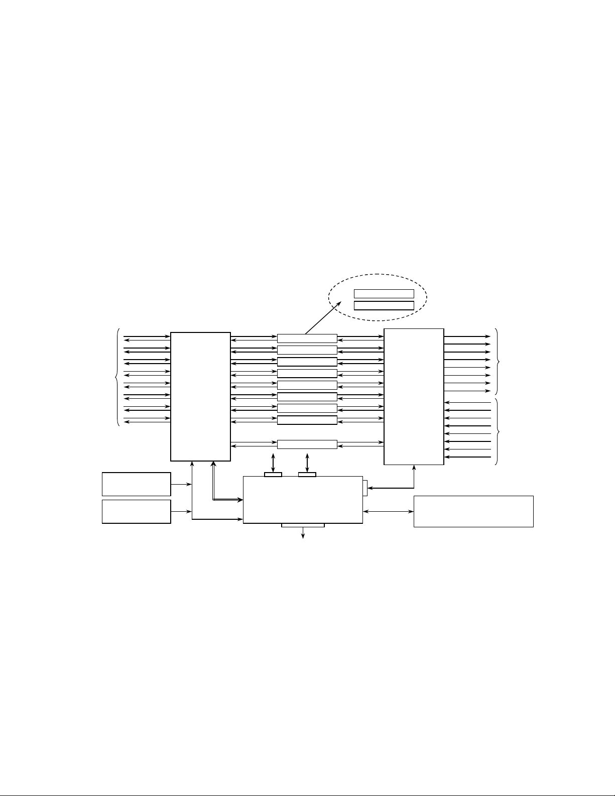
Figure 1-1 CRS-400 Block Diagram with Modems and CRS-280 IF Switch............................ 2
Figure 1-2 CRS-400 Data Switch Block Diagram (TMI #1 is Bridged).................................... 3
Figure 1-3 CRS-280 IF Switch Block Diagram (with TMI and RMI Modules) ........................ 4
Figure 2-1 CRS-400 Front Panel .............................................................................................. 12
Figure 2-2 CRS-400 Rear Panel, with 8 HSSI TMI and 1 HSSI RMI ..................................... 12
Figure 2-3 SCSI-2 (ECL/HSSI) Connector, Pin Locations...................................................... 17
Figure 2-4 HSSI TMI Module .................................................................................................. 22
Figure 2-5 HSSI RMI Module..................................................................................................24
Figure 3-1 Principle Menus Tree for Independent Mode ......................................................... 40
Figure 3-2 Principle Menus Tree for Dependent Mode............................................................ 41
Figure C-1 PC 9-Pin Serial Port to CRS-400 EIA-232 Remote Control Port..........................73
Figure C-2 HSSI Data Cable..................................................................................................... 74
Tables
Table 2-1 HSSI Pinout (J5 / J6 / J7) 50-Pin Mini-D/SCSI-2 Male and Female.......................16
Table 2-2 Systems Alarm Connector Pinout, 25-Pin D Type Female...................................... 18
Table 2-3 IF Switch Control Connector, 25-Pin D Type Male................................................. 19
Table 2-4 Remote Control Connector, 9-Pin D Type Male...................................................... 20
Table 2-5 Auxiliary Serial Connector/Pass-Through, Cable # PL/9195-1...............................21
Table 2-6 HSSI TMI Jumper Selection (TA/CA)..................................................................... 23
Table 2-7 HSSI TMI Jumper Selection (RT/RD).....................................................................23
Table 2-8 HSSI RMI Jumper Selection.................................................................................... 25
Table 2-9 HSSI TMI Jumper Selection (RT/RD).....................................................................25
Table 2-10 CRS-400 to SDM-2020 Data Connection..............................................................26
Table 2-11 CRS-280 IF Switch Connections............................................................................ 31
Table 3-1 Switch LED Indicators ............................................................................................. 38
Table 3-2 Transmit and Receive Traffic Modem LED Indicators............................................ 38
Table C-1 CA/WR9189 Cable Assembly (Pinout, Male/Male, HSSI, Shielded)..................... 75
vii
Page 12
CRS-400 1:8 Redundancy Switch Revision 0
Preface MN/CRS400.IOM
BOUT THIS MANUAL
A
This manual provides installation and operation information for the Comtech EF Data
CRS-400 1:8 Redundancy Switch. This is a technical document intended for earth station
engineers, technicians, and operators responsible for the operation and maintenance of
the CRS-400 1:8 Redundancy Switch.
ELATED DOCUMENTS
R
Comtech EF Data SDM-2020 Satellite Modulator Installation and Operation Manual
Comtech EF Data SDM-2020 Satellite Demodulator Installation and Operation Manual
ONVENTIONS AND REFERENCES
C
AUTION S AND WARNINGS
C
Indicates information critical for proper equipment function.
IMPORTANT
Indicates a hazardous situation that, if not avoided, may result in minor or moderate
injury. CAUTION may also be used to indicate other unsafe practices or risks of
CAUTION
WARNING
ETRIC CONVERSION
M
property damage.
Indicates a potentially hazardous situation that, if not avoided, could result in
death or serious injury.
Metric conversion information is located on the inside back cover of this manual. This
information is provided to assist the operator in cross-referencing English to Metric
conversions.
viii
Page 13

CRS-400 1:8 Redundancy Switch Revision 0
Preface MN/CRS400.IOM
ECOMMENDED STANDARD DESIGNATIONS
R
Recommended Standard (RS) Designations have been superseded by the new designation
of the Electronic Industries Association (EIA). References to the old designations are
shown only when depicting actual text displayed on the screen of the unit (RS-232, RS485, etc.). All other references in the manual will be shown with the EIA designations
(EIA-232, EIA-485, etc.) only.
RADEMARKS
T
All product names mentioned in this manual may be trademarks or registered trademarks
of their respective companies and are hereby acknowledged.
EPORTING COMMENTS OR SUGGESTIONS CONCERNING THIS MANUAL
R
Comments and suggestions regarding the content and design of this manual will be
appreciated. To submit comments, please contact the Comtech EF Data Customer
Support Department.
ix
Page 14

CRS-400 1:8 Redundancy Switch Revision 0
Preface MN/CRS400.IOM
EMC C
EN55022 C
EN50082-1 C
EDERAL COMMUNICATIONS COMMISSION
F
OMPLIANCE
This is a Class A product. In a domestic environment, it may cause radio interference that
requires the user to take adequate protection measures.
OMPLIANCE
This equipment meets the radio disturbance characteristic specifications for information
technology equipment as defined in EN55022.
OMPLIANCE
This equipment meets the electromagnetic compatibility/generic immunity standard as
defined in EN50082-1.
This equipment has been tested and found to comply with the limits for a Class A digital
device, pursuant to Part 15 of the FCC rules. These limits are designed to provide
reasonable protection against harmful interference when the equipment is operated in a
commercial environment.
(FCC)
This equipment generates, uses, and can radiate radio frequency energy. If not installed
and used in accordance with the instruction manual, it may cause harmful interference to
radio communications. Operation of this equipment in a residential area is likely to cause
harmful interference; in which case, users are required to correct the interference at their
own expense.
To ensure compliance, properly shielded cables for DATA I/O shall be used. More
Note:
specifically, these cables shall be shielded from end to end, ensuring a continuous shield.
x
Page 15
CRS-400 1:8 Redundancy Switch Revision 0
Preface MN/CRS400.IOM
AFETY COMPLIANCE
S
EN 60950
Applicable testing is routinely performed as a condition of manufacturing on all units to
ensure compliance with safety requirements of EN60950.
This equipment meets the Safety of Information Technology Equipment specification as
defined in EN60950.
OW VOLTAGE DIRECTIVE
L
The following information is applicable for the European Low Voltage Directive
(EN60950):
(LVD)
<HAR> Type of power cord required for use in the European Community.
CAUTION: Double-pole/Neutral Fusing.
!
ACHTUNG: Zweipolige bzw. Neutralleiter-Sicherung.
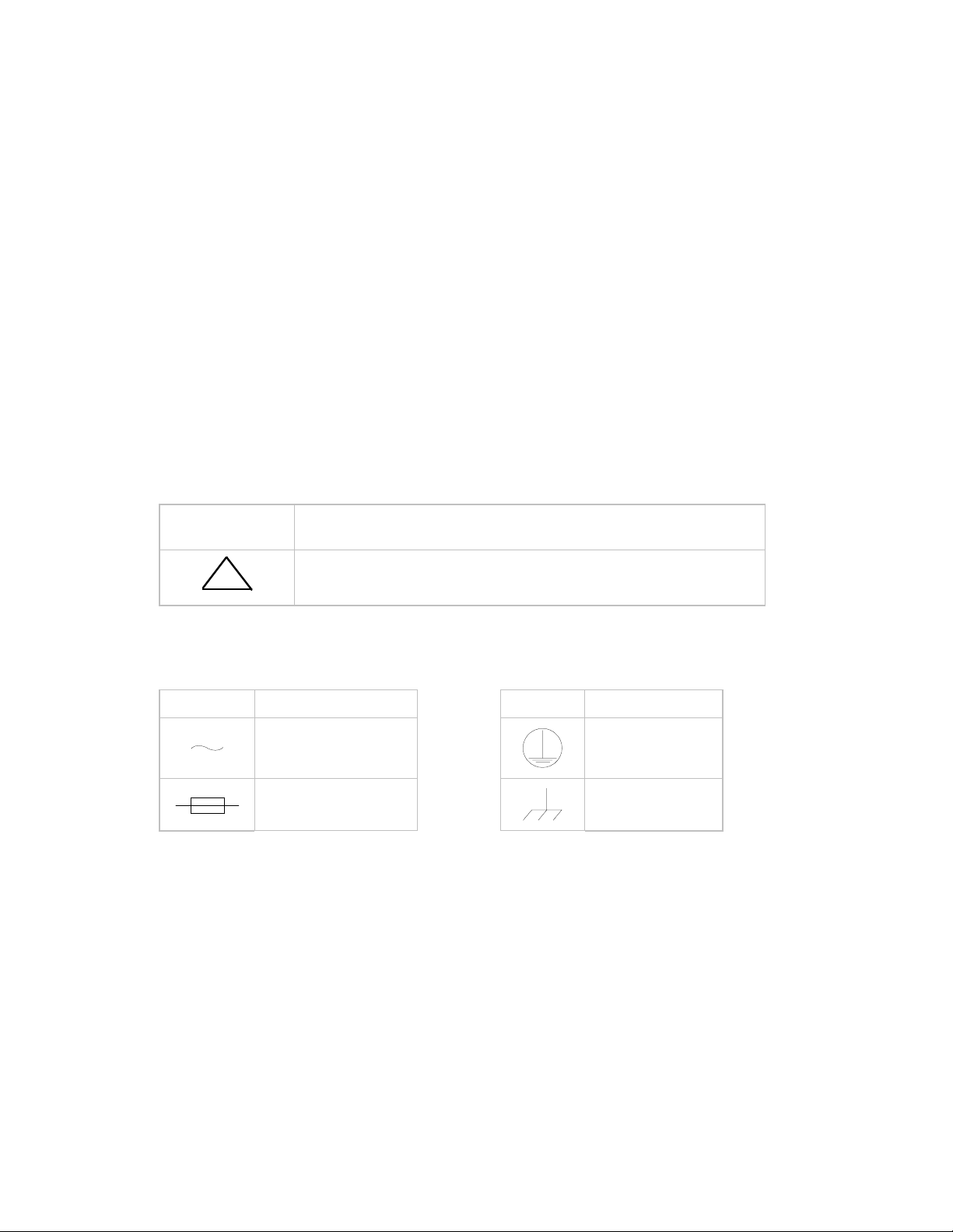
International Symbols:
Symbol Definition Symbol Definition
Alternating Current.
Fuse.
Protective Earth.
Chassis Ground.
For additional symbols, refer to “Cautions” listed earlier in this preface.
Note:
xi
Page 16

CRS-400 1:8 Redundancy Switch Revision 0
Preface MN/CRS400.IOM
ARRANTY POLICY
W
This Comtech EF Data product is warranted against defects in material and workmanship
for a period of two years from the date of shipment. During the warranty period, Comtech
EF Data will, at its option, repair or replace products that prove to be defective.
For equipment under warranty, the customer is responsible for freight to Comtech EF
Data and all related custom, taxes, tariffs, insurance, etc. Comtech EF Data is responsible
for the freight charges only for return of the equipment from the factory to the customer.
Comtech EF Data will return the equipment by the same method (i.e., Air, Express,
Surface) as the equipment was sent to Comtech EF Data.
IMITATIONS OF WARRANTY
L
The foregoing warranty shall not apply to defects resulting from improper installation or
maintenance, abuse, unauthorized modification, or operation outside of environmental
specifications for the product, or, for damages that occur due to improper repackaging of
equipment for return to Comtech EF Data.
No other warranty is expressed or implied. Comtech EF Data specifically disclaims the
implied warranties of merchantability and fitness for particular purpose.
XCLUSIVE REMEDIES
E
The remedies provided herein are the buyer's sole and exclusive remedies. Comtech EF
Data shall not be liable for any direct, indirect, special, incidental, or consequential
damages, whether based on contract, tort, or any other legal theory.
ISCLAIMER
D
Comtech EF Data has reviewed this manual thoroughly in order that it will be an easy-touse guide to your equipment. All statements, technical information, and
recommendations in this manual and in any guides or related documents are believed
reliable, but the accuracy and completeness thereof are not guaranteed or warranted, and
they are not intended to be, nor should they be understood to be, representations or
warranties concerning the products described. Further, Comtech EF Data reserves the
right to make changes in the specifications of the products described in this manual at any
time without notice and without obligation to notify any person of such changes.
If you have any questions regarding the equipment or the information in this manual,
please contact the Comtech EF Data Customer Support Department.
xii
Page 17
Chapter 1. Introduction
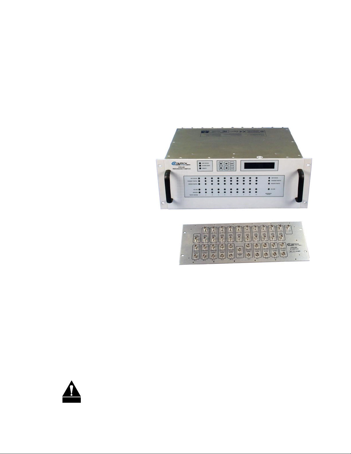
CRS-400
1:8 Redundancy
Switch
Optional CRS-280
IF Switch
1.1 D
ESCRIPTION
The Comtech EF Data CRS-400 1:8 Redundancy Switch is designed for use with the
Comtech EF Data SDM-2020 modulator and demodulator to provide fully automatic
protection of traffic circuits in case of equipment failure. It is intended for hub and other
redundancy applications and currently supports the HSSI interface type.
Connection to the traffic modulators/demodulators and the redundant
modulator/demodulator is simple – a Data cable, which carries all data signals and alarm
information, a 485 cable for remote control interfaces, and, in some cases, a fault cable.
This simplifies rack cabling, and reduces the number of potential failure points.
CAUTION
The Comtech EF Data CRS-400 switch is designed specifically as an accessory
product for the Comtech EF Data SDM-2020 modulator and demodulator and is
not designed to operate with any other manufacturer’s equipment.
1
Page 18
CRS-400 1:8 Redundancy Switch Revision 0
Introduction MN/CRS400.IOM
The CRS-400 is fully modular in construction. All replaceable modules insert into slots in
the rear. This includes the Controller, Power Supply Units (PSU), Traffic Modem
Interface (TMI) and the Redundant Modem Interface (RMI). Power consumption is
below 25 W for a fully populated switch, so no fan cooling is required.
The CRS-400 incorporates the following key reliability features:
Twin, independent, AC power supplies
Maintains normal traffic paths, error free, when AC power is removed
: Redundant Modulator/Demodulator traffic returns to normal traffic path if power is lost
Note
Modulator
Or
Demodulator
To
User
Equipment
1
2
3
4
5
6
7
IF
8
1
2
3
4
5
6
7
8
Front Panel Keyp ad ,
LCD and LE D Display
CRS-400
To
Up
Converters
From
Down
Converters
CRS-240
Power Supply
CRS-240
Power Supply
CRS-400.ppt
1
2
Traffic
3
Modem
Switches
4
(TMI)
5
6
7
Redundant
Modem
8
Switch
(RMI)
Redundant
1
2
3
4
5
&
6
7
8
Remote
Pass-Thru
Modem 1
Modem 2
Modem 3
Modem 4
Modem 5
Modem 6
Modem 7
Modem 8
Modem Re dund
Remote Contro l
To All Modems
CRS-230
Controller
System Alarms
1
2
3
4
5
6
7
8
Redundant
IF Switch
Control
CRS-280
Switch
(Optional)
Figure 1-1 CRS-400 Block Diagram with Modems and CRS-280 IF Switch
The function of the CRS-400 Redundancy Switch is depicted in Figure 1-1. User data enters and exits the switch at the left hand side of the diagram, while IF leaves and enters
from the right. The data and clock signals to and from a traffic modulator/demodulator
are routed through a TMI, via a set of relays. There are up to 8 TMIs in the switch,
labeled 1 through 8 in the figure. The relays in the TMI are arranged so that the
unpowered state connects the data signals directly through to the traffic
modulator/demodulator. If the power supplies to the system are lost, or if a TMI carrying
traffic is removed, traffic is not interrupted. In normal circumstances, when the redundant
modulator/demodulator is not in service, no data is carried through the CRS-400
backplane – all data is routed through the TMI.
2
Page 19
CRS-400 1:8 Redundancy Switch Revision 0
Introduction MN/CRS400.IOM
There are several other key operational features of the CRS-400 architecture:
“Bridging” a traffic modulator/demodulator clock and data: A copy of the data and
clock signals feeding a particular modulator/demodulator is selectively routed to the
redundant modulator/demodulator.
“Bridging” a traffic modulator/demodulator IF: RMI Rx IF is tuned to receive any
selected carrier.
Live traffic may be checked on the redundant demodulator when the traffic
demodulator is placed in “bridge” mode.
There are two ways to set up the CRS-400 for IF operation. The first method does not
require an optional IF switch and is used when all modulators/demodulators within a
group are connected to the same up/down converter.
The second method is used when operation with more than one up/down converter is
required. In this case, adding the CRS-280 IF Switch permits connections to as many
converters as traffic modulators/demodulators.
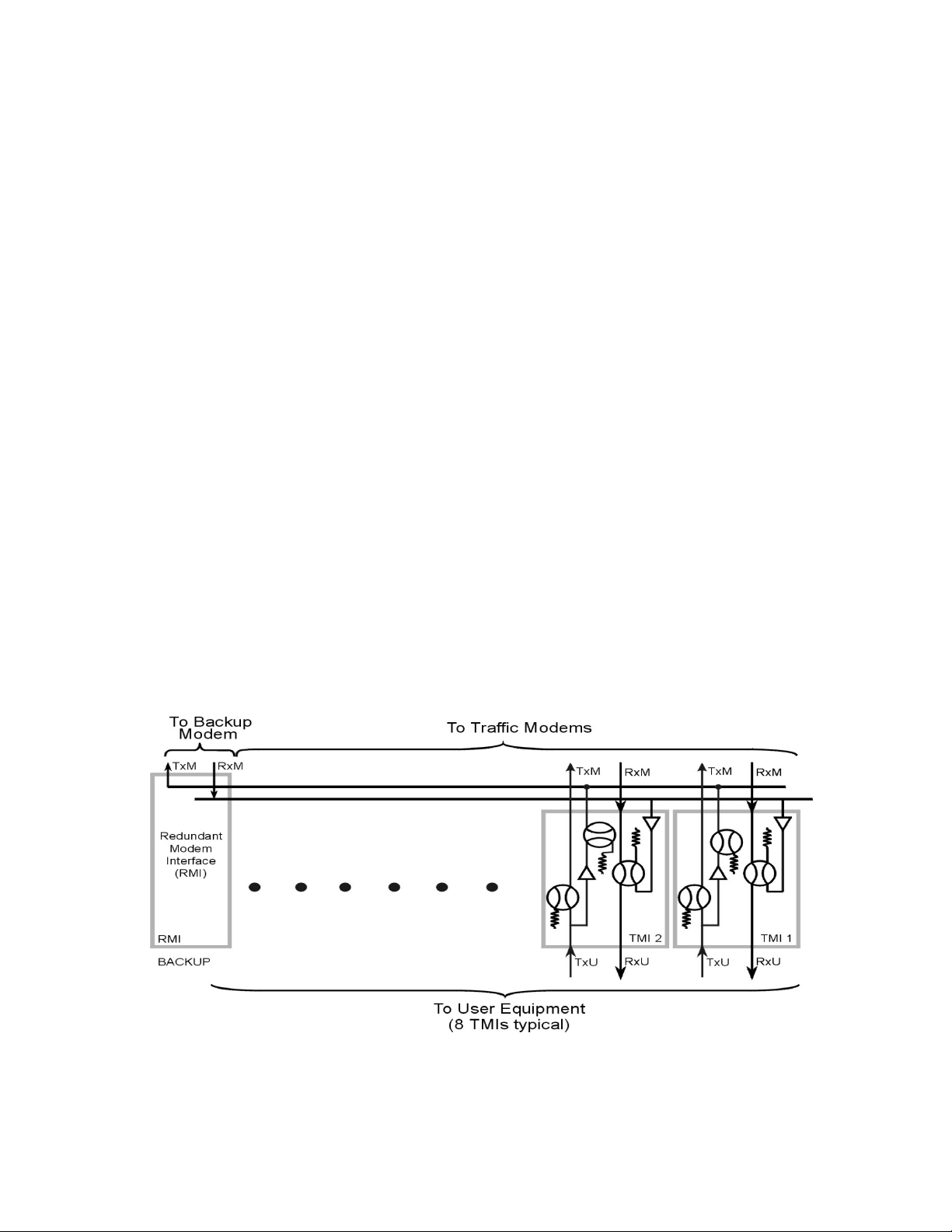
The data switch and IF switch are shown in Figure 1-2 and Figure 1-3, respectively. Data
enters the TMI modules (CH1 - CH8) at the bottom of Figure 1-2. The Tx data entering
each channel is routed through the TMI and sent out to the traffic modulators/demodulators. The Tx data and clock are also buffered by an amplifier to make them
available for bridging and routing through the RMI.
Figure 1-2 CRS-400 Data Switch Block Diagram (TMI #1 is Bridged)
3
Page 20
CRS-400 1:8 Redundancy Switch Revision 0
g
Introduction MN/CRS400.IOM
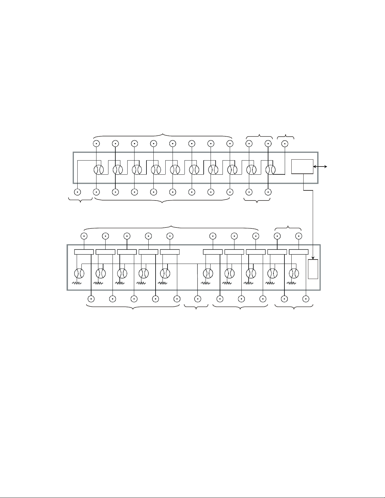
Figure 1-3 depicts the separate Tx and Rx sections of the optional IF switch. Either in the
non-energized state of the relays, or when the switch is not powered, the IF traffic is
routed straight through on the primary units. Traffic enters the Tx section of the switch
from the bottom of the switch and leaves from the top. In the Rx section of the switch,
traffic flows in the opposite direction. There is a loss of 3 dB in the demodulator path
because of the receive splitter.
To Up Converters
UC1 UC2 UC3 UC4 UC5 UC6 UC 7 UC8 UC9 UC10
Tx2Tx1 Tx3 Tx4 Tx5 Tx6 Tx7 Tx8 Tx9 Tx10TxBU
From Redundant
Modulator
DC1 DC2 DC3 DC4 DC5 DC6 DC7 DC8 DC9 DC10
Splitter Splitter Splitter Splitter Splitter Splitter Splitter Splitter Splitter Splitter
Rx1 Rx2 Rx3 Rx4 Rx5 Rx6 Rx7 Rx8 Rx9 Rx10RxBU
CRS-400.ppt
To Demodulators 1 Through 5
From Modulators 1 Through 8
From Down Converters Not Used
Demodulator
Switch
Demodulator
Not Used
Not Used
Test Point
Modulator Switch
Controller
Interface
Drivers
h 8To Redundant
Not UsedTo Demodulators 6 Throu
Figure 1-3 CRS-280 IF Switch Block Diagram (with TMI and RMI Modules)
All of the modulators/demodulators are connected to the CRS-400 via a single, 9-pin,
EIA-485, multi-drop cable and the HSSI cable. The EIA-485 link permits the CRS-400 to
determine and store a modulator/demodulator’s configuration, and to send a chosen
configuration to the redundant modulator/demodulator.
4
Page 21

CRS-400 1:8 Redundancy Switch Revision 0
Introduction MN/CRS400.IOM
1.2 F
RONT AND REAR PANELS
The front panel contains the Vacuum Fluorescent Display (VFD), keypad, and several
LED indicators. Enter data via the keypad, and messages are displayed on the VFD.
Behind the front panel, there is an audio alarm that can be controlled to respond to
various faults.
External cables are attached to connectors on the rear panel of the CRS-400’s plug-in
modules.
The connectors are listed below for reference.
Data connector to each Mod/Demod
User Data Interface connector for each traffic Mod/Demod to the outside world
System Alarms connector
Remote Control connector
Auxiliary EIA-485 connector, (Pass-Through)
Diagrams of the front and back panels are shown in Chapter 2.
5
Page 22

CRS-400 1:8 Redundancy Switch Revision 0
Introduction MN/CRS400.IOM
1.3 M
AJOR ASSEMBLIES AND OPTIONS
Part Number Description Model # Comments Install Option
Main Unit Chassis,
Motherboard and Display
AS/9163 Traffic Modem Interface, HSSI CRS-410 Option User
AS/9165 Redundant Modem Interface, HSSI CRS-412 Option User
AS/0377 System Controller CRS-230
AS/0376 Power Supply: 100–250 VAC CRS-240 With Main Unit User
FP/CV9167 Blank Panel Option User
PL/WR9212-1 485 Multi-drop cable With Main Unit User
AS/8976-2 I/F Switch: 50 Ohm
(Not Available)
AS/8976-1 I/F Switch: 75 Ohm CRS-280-1 Option User
PL/WR9195-6 HSSI – 6 foot cable Option With
PL/0946-1 IF BNC to BNC 50 Ohm,
4 foot cable
Main Unit Factory
CRS-280-2 Option User
User
Main Unit
Spare User
PL/0946-2 IF BNC to BNC 50 Ohm,
8 foot cable
PL/0813-4 IF BNC to BNC 75 Ohm,
4 foot cable
PL/0813-8 IF BNC to BNC 75 Ohm,
8 foot cable
Option With
Main Unit
Spare User
Option With
Main Unit
User
User
6
Page 23

CRS-400 1:8 Redundancy Switch Revision 0
Introduction MN/CRS400.IOM
1.4 S
PECIFICATIONS (PRELIMINARY
Characteristic Requirement
AC Prime Power Two independent inputs,
Size/Weight
Data Switch/Control Unit
IF Switch Unit
Environmental
Temperature
Humidity
)
90 to 264 VAC; 50/60 Hz;
at 25 Watts
4U 19 in. by 20.1 in. deep, Rack Mount
(4U 48.26 cm W by 51.054 cm D)
< 20 pounds (< 9.07 kg)
4U 19 in. by ~4.5 in. deep, Rack Mount
(4U 48.26 cm W by 11.43 cm D)
< 10 pounds (<4.54 kg)
0 to +40°C Operating
-50 to +100°C Storage
95% at +40°C, Non-condensing
EMC And Safety EN 55022 Class B emissions
EN 50082-1 immunity
EN 60950 Safety
FCC Part 15 Class B
7
Page 24

CRS-400 1:8 Redundancy Switch Revision 0
Introduction MN/CRS400.IOM
1.4.1 D
Characteristic Requirement
Number of Prime
Mods/Demods
Number of Backup
Mods/Demods
Operating Mode - Data
Switch
Operating Mode - IF Switch Dependent or Independent
Mod/Demod
Priority/Programmable
Switching Hold Off Time 2 to 99 Seconds
Switching Manual or Auto
Default on Power Loss Redundant Modulator/Demodulator traffic returns to the normal
Operating Modes Fully Automatic
ATA REDUNDANCY AND CONTROLLER
1 to 8
1
Dependent or Independent
1 Bridge Mode
traffic path.
Manual, force backup to replace selected traffic channel
Manual, force backup to parallel traffic channel, Bridge
Remove selected traffic channel from control, Active or Not Active
User interface/Connector
(8 Data/TMI Channels)
Configuration Control Remote:
Tx Offline Activity Bridged unit receives a copy of the clock and data from one of the
HSSI to 70 Mbit/s SCSI-2 female
75 Ohm, Supporting : BNC-Female
EIA-485/232-C, programmable
Both switch and mod/demod communications
Manual:
Menu driven from switch front panel
Both switch and mods/demods
traffic channels. User designates the traffic channel.
8
Page 25

CRS-400 1:8 Redundancy Switch Revision 0
Introduction MN/CRS400.IOM
1.4.2 CRS-280 IF R
Characteristic Requirement
Tx/Rx Operating Frequency 50 to 180 MHz
Return Loss 18 dB return loss into 75Ω (50Ω optional)
Tx to Tx Channel Isolation > 50 dB
Rx to Rx Channel Isolation > 50 dB
Tx to Rx Channel Isolation > 60 dB
Number of Uplinks 1 to 8 traffic mods/demods
Transmit IF Loss < 1.5 dB over operating frequency
Receive IF Loss < 5 dB over operating frequency
Tx / Rx Connectors BNC female
L-Band IF Switch
Number of Downlinks 1 to 8 traffic units
Powering of IF Switch From the CRS-400 chassis for 70 / 140 MHz or L-Band
EDUNDANCY SWITCH SPECIFICATIONS
Switch
9
Page 26
CRS-400 1:8 Redundancy Switch Revision 0
Introduction MN/CRS400.IOM
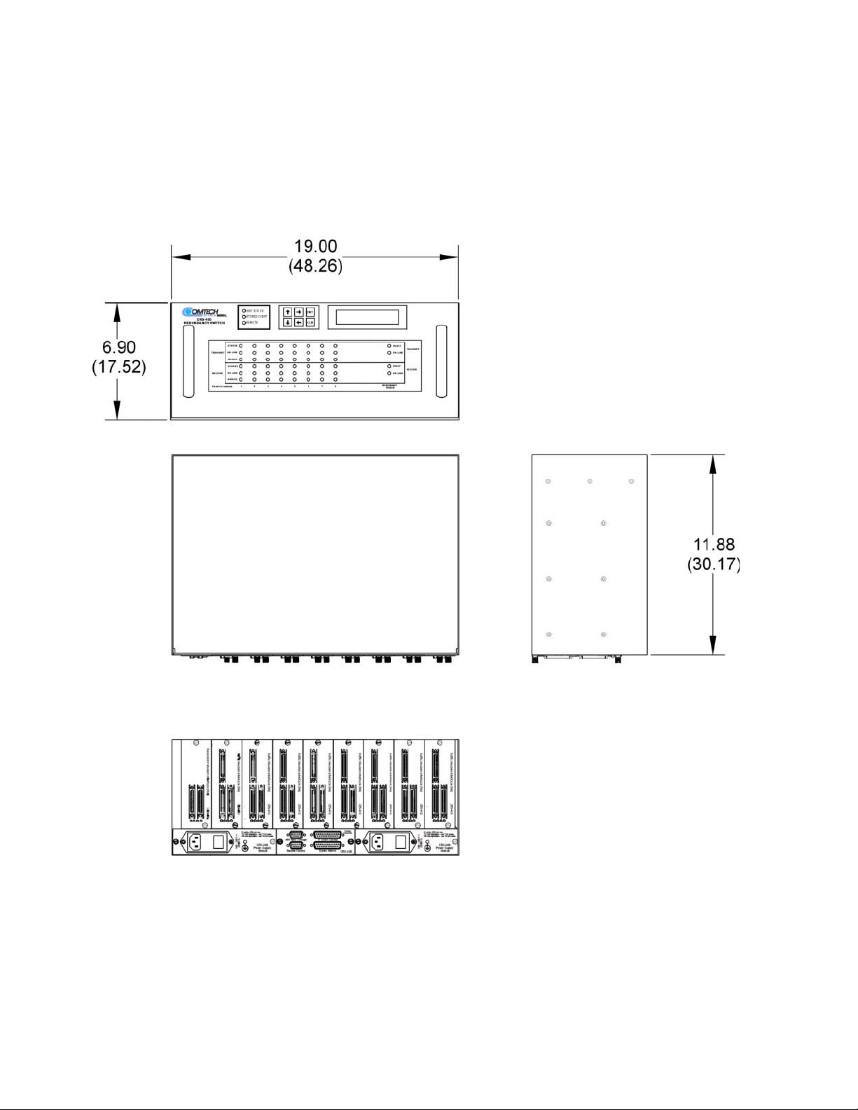
1.4.3 O
UTLINE DRAWING
Dimensions are shown in both inches and (centimeters).
10
Page 27

Chapter 2. Installation and Initial Setup
Unpacking and Inspection
Front Panel
Rear Panel
Mounting Instructions
Installation Details
Cables and Connectors
TMI Modules
RMI Modules
Connecting the Cables
Configuring the Mods/Demods – Firm ware Vers ions
Applying Power to the Switch
Configuring the Switch
Configuring the IF Carriers
Configuring Automatic Operation Mode
13
13
13
14
15
15
22
24
26
27
28
29
30
32
: The term “modulator/demodulator” will be abbreviated to “mod/demod” throughout the
Note
remainder of this chapter.
11
Page 28
CRS-400 1:8 Redundancy Switch Revision 0
Installation and Setup MN/CRS400.IOM
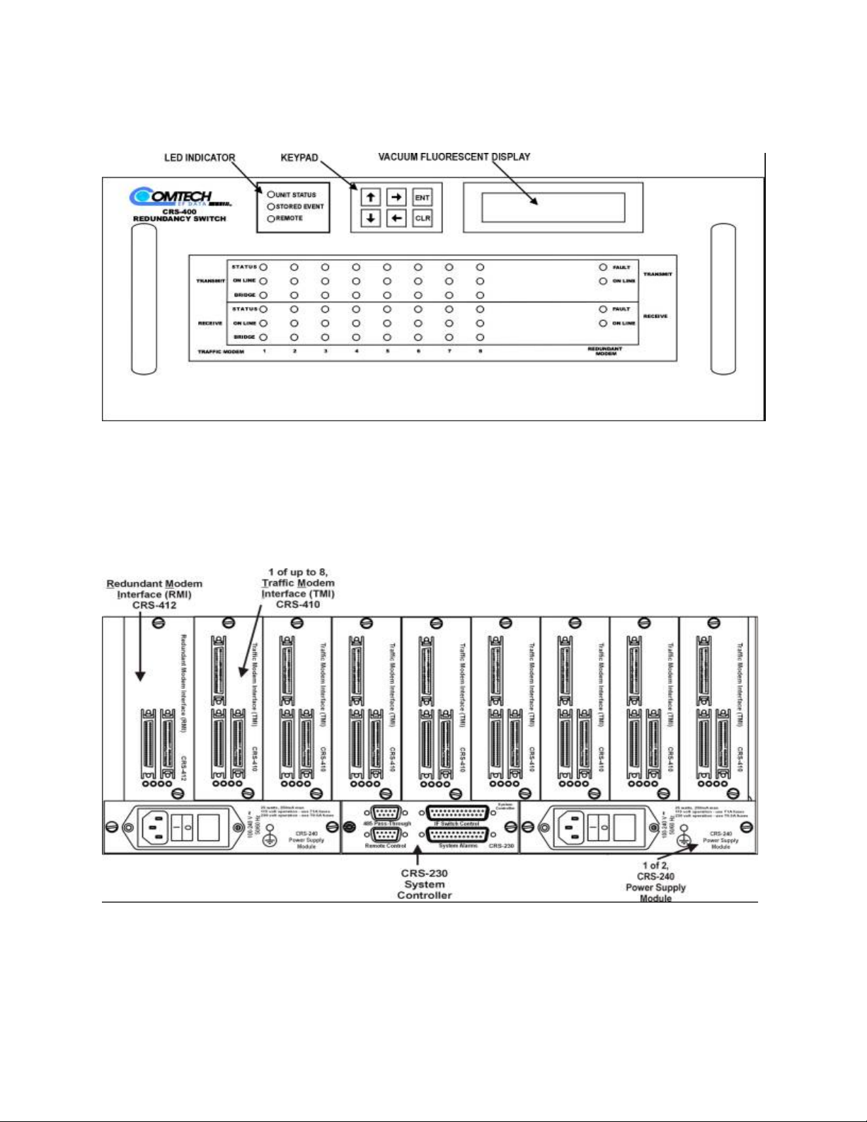
Figure 2-1 CRS-400 Front Panel
Figure 2-2 CRS-400 Rear Panel, with 8 HSSI TMI and 1 HSSI RMI
12
Page 29

CRS-400 1:8 Redundancy Switch Revision 0
Installation and Setup MN/CRS400.IOM
2.1 U
2.2 F
NPACKING AND INSPECTION
1
Inspect shipping containers for damage.
If shipping containers are damaged, keep them until the contents of the shipment have
been carefully inspected and checked for normal operation.
2
Remove the packing list from the outside of the shipping carton.
3
Open the carton and remove the contents.
4
Check the contents against the packing list to verify completeness of the shipment.
5
If damage is evident, contact the carrier and Comtech EF Data immediately and submit a
damage report.
6
Be sure to keep all shipping materials for the carrier's inspection.
If the unit needs to be returned to Comtech EF Data, please use the original shipping
container.
RONT PANEL
Figure 2-1 is an illustration of the front panel. The CRS-400 is constructed as a 4U high
rack-mounting chassis that can be freestanding, if desired. It is provided with rackhandles at the front for easy removal from and placement into a rack.
2.3 R
EAR PANEL
The connectors on the rear panel (see Figure 2-2) of the CRS-400 include:
Data connectors
Data connector to each Mod/Demod
User Data Interface connector for each traffic Mod/Demod to the outside world
Redundant Modem Interface (RMI) connectors
System Alarms connector
Remote Control connector
Auxiliary (Pass-Through) EIA-485 connector, 19200 baud with 7-E-2 (7 Data bits,
Even parity, and 2 Stop bits protocol only)
IF Switch Control connector
Power Supply connectors
13
Page 30

CRS-400 1:8 Redundancy Switch Revision 0
Installation and Setup MN/CRS400.IOM
2.3.1 D
The Data connectors on the TMI plug-ins lead to/from the mods/demods, and lead
to/from the outside world (User Data).
The User Data female connector can be treated as an extension of the traffic
mod/demod’s Data connector. The RMI has no User Data connector, since it will only
replace one of the traffic mods/demods. The pinout for both connectors is provided in the
next chapter.
Open Collector TTL (OC-TTL) signals for mod/demod faults are used to initiate
switching in the CRS-400 switch. The conductors are either in the data cable or in a
separate cable, depending upon the type of data interface.
Note
2.4 M
ATA CONNECTORS
: It is the user’s responsibility to provide the appropriate User Data cable to connect
between the outside user equipment and the TMI.
Reliable Data cables are available from Comtech EF Data to connect between the TMI
(or RMI) and the Mod (or Demod).
OUNTING INSTRUCTIONS
The CRS-400 is constructed as a 4U high rack-mounting chassis. Rack-handles at the
front of the unit facilitate removal from and placement into a rack.
Mount the switch in the rack using the mounting holes on the front panel.
For the CRS-400 to operate correctly, identical types of Mod/Demod models must be
used for all traffic Mods/Demods, and for the redundant Mod/Demod.
2.4.1 P
Typically, the CRS-400 is mounted in a rack along with all the Mods/Demods with which
it is to operate, so it is important to ensure that there is adequate clearance for ventilation.
Since the switch itself is relatively passive, no additional clearance is needed between it
and the nearest Mod/Demod.
In rack systems where there is high heat dissipation, provide forced-air cooling by
installing top- or bottom-mounted fans or blowers.
DO NOT MIX MODELS OF MODS/DEMODS CONNECTED TO THE SWITCH
WARNING
ROVIDE AIRFLOW
14
Page 31

CRS-400 1:8 Redundancy Switch Revision 0
Installation and Setup MN/CRS400.IOM
o
C.
CAUTION
Do not allow the internal rack temperature to exceed 50
2.4.2 A
Mount the switch using front panel screws only. Do not install rack slides to the side of
the CRS-400 chassis. Contact the factory if there are questions about rack supports.
2.5 I
Cable connections for the switch are wired on a channel by channel basis as indicated in
Figure 1-1 of Chapter 1, a block diagram of the CRS-400. Further detail for the data
switch and IF switch is provided in Chapter 1, Figure 1-2 and Figure 1-3. The subsequent
tables provide the detail cable connections between the CRS-400 and the mods/demods
and other interfaces.
In Paragraph 2.13 a separate connection table is presented for connections made to the
optional IF switch.
2.6 C
Please use the following information to verify that you have the correct cables and
connectors available prior to installing the unit.
BOUT RACK SUPPORT
NSTALLATION DETAILS
ABLE S AN D CONNECTORS
IMPORTANT
2.6.1 HSSI C
The HSSI cables required between each Mod/Demod and its plug-in card (TMI or RMI)
should be of shielded, twisted-pair construction with the grounded shield bonded to the
back shell. All 50 pins should be wired to the same pin number at either connector (pinto-pin), with a male connector at both ends. The Data and Clock must be on twisted-pair
cable.
Appropriate HSSI cables lengths are available from Comtech EF Data, so please consult
the factory for ordering information. Please note that these cables are an extra-cost item.
Comtech EF Data can supply IF cables or IF splitters/combiners with the
CRS 280 Redundancy Switch as an option.
ABLE PHYSICAL REQUIREMENTS
15
Page 32

CRS-400 1:8 Redundancy Switch Revision 0
Installation and Setup MN/CRS400.IOM
2.6.2 TMI D
ATA CONNECTOR
(HSSI)
Table 2-1 describes the pinout for the HSSI connector. User equipment connects to the
CRS-400 at J5. Make the connections from the CRS-400 to the mod/demod using J6 and
J7 for the modulator and demodulator, respectively. Two connectors, J6 and J7, are
provided to eliminate the need for a Y-cable between the mod/demod and the switch
when the modulator and demodulator are housed in separate chassis. Use only J6 when
connecting a combined modulator and demodulator (modem) to the switch.
Table 2-1 HSSI Pinout (J5 / J6 / J7) 50-Pin Mini-D/SCSI-2 Male and Female
HSSI/EIA-613 Interface Connector Pinout -- J6 / J7 To modem J5 To User
Signal Function HSSI
Signal
Signal Ground SG 102 1, 26 Mod/Demod 1, 26
Receive Timing RT 115 2, 27 from DCE Demodulator 2, 27
DCE Available CA 107 3, 28 from DCE Mod/Demod 3, 28
Receive Data RD 104 4, 29 from DCE Demodulator 4, 29
Loopback Circuit C LC undefined 5, 30 from DCE Mod/Demod unused
EIA-613
Circuit
Pin # (+, -) Circuit
Direction
Comment Pin # (+, -)
Send Timing ST 114 6, 31 from DCE Modulator 6, 31
Signal Ground SG 102 7, 32 Mod/Demod 7, 32
DTE Available TA 108/2 8, 33 to DCE Mod/Demod 8, 33
Terminal Timing TT 113 9, 34 to DCE Modulator 9, 34
Loopback Circuit A LA 143 10, 35 to DCE Mod/Demod unused
Send Data SD 103 11, 36 to DCE Modulator 11, 36
Loopback Circuit B LB 144 12, 37 to DCE Mod/Demod unused
Signal Ground SG 102 13, 38 Mod/Demod 13, 38
TX PSYNC
TX DVALID
Reserved (to DCE) 16, 41 unused unused
Reserved (to DCE) 17, 42 unused unused
Reserved (to DCE) 18, 43 unused unused
Signal Ground SG 102 19, 44 Mod/Demod 19, 44
Carrier Detect (lock)
(Notes 1 and 2)
(Note 1)
TPSYNC undefined 14, 39 to DCE Modulator unused
(Note 1)
TDVALID undefined 15, 40 to DCE Modulator unused
CD undefined 20 from DCE Demodulator 20
16
Page 33

CRS-400 1:8 Redundancy Switch Revision 0
Installation and Setup MN/CRS400.IOM
HSSI/EIA-613 Interface Connector Pinout -- J6 / J7 To modem J5 To User
Signal Function HSSI
Signal
Demod Fault
(Notes 1 and 3)
Mod Fault
(Notes 1 and 3)
DF undefined 45 from DCE Demodulator unused
MF undefined 21 from DCE Modulator unused
EIA-613
Circuit
Pin # (+, -) Circuit
Direction
Comment Pin # (+, -)
Reserved (to DTE) 46 unused unused
RX PSYNC
RX DVALID
(Note 1)
RPSYNC undefined 22, 47 from DCE Demodulator unused
(Note 1)
RDVALID undefined 23, 48 from DCE Demodulator unused
Test Mode TM 142 24, 49 from DCE Mod/Demod unused
Signal Ground SG 102 25, 50 Mod/Demod 25, 50
:
Notes
1) Noted signal function names are non-HSSI defined signals. On Cisco routers there is no
connection to those pins. Refer to the Comtech EF Data web site for an Application Note
describing the use of the SDM-2020 with Cisco routers.
2) TTL - output.
3) TTL – open collector output.
The HSSI interface uses the type of SCSI-2 connector shown in Figure 2-3.
Figure 2-3 SCSI-2 (ECL/HSSI) Conn ec tor , Pin Loca ti ons
17
Page 34

CRS-400 1:8 Redundancy Switch Revision 0
Installation and Setup MN/CRS400.IOM
2.6.3 S
Located on the System Controller card, the System Alarms connector provides access to
Form-C relay contacts that indicate the fault status of the switch and the summary faults.
If any of the attached mods/demods has any fault active, the corresponding Tx or Rx
summary relay will energize, forcing the normally open pin to connect to (and the
normally closed pin to disconnect from) the common pin.
Another pin provides a ground connection when the audio alarm is sounded so that the
user may add additional audible alarms.
There are also relay contacts to indicate which, if any, of the traffic mods/demods is
currently being backed up. To determine which mod/demod is being backed up (see the
connector pinout, Table 2-2), decode the BCD relay outputs.
YSTEM ALARMS CONNECTOR
Table 2-2 Systems Alarm Connector Pinout, 25-Pin D Type Female
Pin Description
13 Unused Rela y – NC Contac t
25 Unused Rela y – NO Contac t
12 Mod/demod Summary Rx Traffic Fault – NC Contact
24 Mod/demod Summary Rx Traffic Fault – NO Contact
11 Mod/demod Summary Tx Traffic Fault – NC Contact
23 Mod/demod Summary Tx Traffic Fault – NO Contact
10 Mod/demod Summary Unit Fault – NC Contact
22 Mod/demod Summary Unit Fault – NO Contact
9 Switch Unit Fault – NC Contact
21 Switch Unit Fault – NO Contact
8 Common contact for pins 9-12 and 21-24
20 Audio Indicator (Gnd = Audio on Float = Audio off)
7 Ground
19 Not Connected
6 BU Mod Replaces Traffic Mod “N”, Bit 1 of 3 – NO Contact
18 BU Mod Replaces Traffic Mod “N”, Bit 2 of 3 – NO Contact
5 BU Mod Replaces Traffic Mod “N”, Bit 3 of 3 – NO Contact
17 Unused Rela y – NO Contac t
4 BU Demod Replaces Traffic Demod “N”, Bit 1 of 3 – NO Contact
18
Page 35

CRS-400 1:8 Redundancy Switch Revision 0
Installation and Setup MN/CRS400.IOM
Pin Description
16 BU Demod Replaces Traffic Demod “N”, Bit 2 of 3 – NO Contact
3 BU Demod Replaces Traffic Demod “N”, Bit 3 of 3 – NO Contact
15 Unused Rela y – NO Contac t
2 Unused Relay – NO Contact
14 Unused Rela y – NO Contac t
1 Common contact for pins 3-6 and 15-18
* Note
: Mod/demod Select 0-3 represent the binary address of the Mod/Demod.
2.6.4 IF S
The IF Switch Control connector should be cabled directly to the corresponding
connector on the CRS-280 IF Switch, if used. This supplies power to the CRS-280, along
with the logic interface to drive the currently selected traffic mod/demod, and to decide
whether the system is in bridged or back-up mode. The CRS-280 must perform the same
bridging and backing up functions to the transmit and receive IF signals to match what
the CRS-400 does to the terrestrial data signals. Table 2-3 provides the pinout
information.
WITCH CONTROL CONNECTOR
Table 2-3 IF Switch Control Connector, 25-Pin D Type Male
Pin # Condition
16
Enable
5 Clock
17 Serial Data
4 Mod_Backup
8 Demod_Backup
3 Rev_Bit0, (for PCA hardware revision control)
18 Rev_Bit1
6 Rev_Bit2
19 Rev_Bit3
7 Product_ID_Bit0, (for IF switch identification)
20 Product_ID_Bit1
21 IF Switch Present
19
Page 36

CRS-400 1:8 Redundancy Switch Revision 0
Installation and Setup MN/CRS400.IOM
Pin # Condition
10, 22 +5V input
12, 24 +12V input
11, 13 Ground
1, 2, 9, 14, 15 No Connection
2.6.5 R
The Remote Control connector provides access to the remote control ports of the switch,
both EIA-232 and EIA-485. Table 2-4 provides the pinout information.
EMOTE CONTROL CONNECTOR
Table 2-4 Remote Control Connector, 9-Pin D Type Male
Pin Description
1 Ground
9 EIA-485 Transmit Data B
8 EIA-485 Transmit Data A
5 EIA-485 Receive Data B
4 EIA-485 Receive Data A
2 EIA-232 Transmit Data
3 EIA-232 Receive Data
6 Not connected
7 Not connected
20
Page 37

CRS-400 1:8 Redundancy Switch Revision 0
Installation and Setup MN/CRS400.IOM
2.6.6 A
This connector is used for switch remote control of each SDM-2020 modulator or
demodulator. This remote communication is fixed at a rate 19200 Baud with 7-E-2
character format. Ensure that each mod/demod is set for EIA-485 4-wire communications
and the matching protocol and baud rate.
The pinout for EIA-485 communication at the switch is the same as the remote control on
the SDM-2020 modems. Table 2-5 provides the pinout information.
UXILIARY SERIAL CONNECTOR
Table 2-5 Auxiliary Serial Connector/Pass-Through, Cable # PL/9195-1
CRS-400
9-Pin D
Male Description VO
9 EIA-485 Receive Data B I
8 EIA-485 Receive Data A I
5 EIA-485 Transmit Data B O
4 EIA-485 Transmit Data A O
ASS-THROUGH
/ P
1 Ground
2 Not connected
3 Not connected
6 Not connected
7 Not connected
21
Page 38

CRS-400 1:8 Redundancy Switch Revision 0
Installation and Setup MN/CRS400.IOM
2.7 TMI M
The following paragraphs describe settings for any of the individual TMI modules that
require jumper or other installation settings on the module.
2.7.1 HSSI M
An outline drawing of the HSSI interface is shown in Figure 2-4. The jumper settings are
explained in Table 2-6 and Table 2-7.
Recommended Setting: CA looped to TA at J5.
J5 User DataInterface
J7 De mod
J6 Mod / Modem
Terrestrial Modem Interface (TMI)
ODULES
ODULE
J2
J1
12
J2
78
12
J1
78
J10 J9
J3
On Line
On Line
Bridged
Bridged
CRS-400.
HSSI TMI
12
J3
78
Jumpers Shown In
Default Position
Figure 2-4 HSSI TMI Module
22
Page 39

CRS-400 1:8 Redundancy Switch Revision 0
Installation and Setup MN/CRS400.IOM
Table 2-6 HSSI TMI Jumper Selection (TA/CA)
TA/CA Selection J1 Jumpers J2 Jumpers J3 Jumpers
Default: CA Looped to TA at J5 5 - 6
Modulator Only or Mod/Demod.
J5-TA to Modulator,
CA From Modulator to J5.
Demodulator Only.
CA from Demod to J5
(TA ignored)
Table 2-7 HSSI TMI Jumper Selection (RT/RD)
RT/RD Selection J9 Jumpers J10 Jumpers
Default: RT/RD from Demod 5 - 6
RT/RD from Modem
(Full Duplex at J6)
7 - 8
1 - 2
3 - 4
1 - 2
3 - 4
7 - 8
1 - 2
3 - 4
1 - 2
3 - 4
5 - 6
7 - 8
1-2
3-4
1 - 2
3 - 4
None 5 - 6
7 - 8
5 - 6
7 - 8
1 - 2
3 - 4
23
Page 40

CRS-400 1:8 Redundancy Switch Revision 0
Installation and Setup MN/CRS400.IOM
2.8 RMI M
The following paragraphs describe settings for any of the individual RMI modules that
require jumper or other installation settings on the module.
2.8.1 HSSI M
Figure 2-5 shows the RMI module, Table 2-8 and Table 2-9 describe the jumper settings
on the module.
ODULES
ODULE
Figure 2-5 HSSI RMI Module
24
Page 41

CRS-400 1:8 Redundancy Switch Revision 0
Installation and Setup MN/CRS400.IOM
Table 2-8 HSSI RMI Jumper Selection
TA/CA Selection J1 Jumpers
Default: Modulator Only or Mod/Demod.
CA From Modulator to J6.
Demodulator Only.
CA from Demod to J7 (TA ignored)
1 - 2
3 - 4
5 - 6
7 - 8
Table 2-9 HSSI TMI Jumper Selection (RT/RD)
RT/RD Selection J9 Jumpers J10 Jumpers
Default: RT/RD from Demod 5 - 6
7 - 8
RT/RD from Modem
(Full Duplex at J6)
1 - 2
3 - 4
5 - 6
7 - 8
1 - 2
3 - 4
25
Page 42

CRS-400 1:8 Redundancy Switch Revision 0
Installation and Setup MN/CRS400.IOM
2.9 C
ONNECTING THE CABLES
WARNING
All Mods/Demods must be the same model and contain the same software revision so
that the Redundant Mod/Demod can properly mimic all traffic Mods/Demods.
2.9.1 HSSI C
1
Connect HSSI data cables between each traffic Mod/Demod and TMI card.
2
Connect a HSSI data cable between the redundant Mod/Demod and the RMI card.
3
Replace any unused cards with blank panels .
4
Connect the multidrop cable (PL/WR9212-1) from the Pass-Through connector to each
SDM-2020 remote port.
5
Do not connect the IF ports at this time.
6
Apply power to the Mods/Dem ods only.
Table 2-10 lists connections made between the CRS-400 and SDM-2020 units.
Ensure that all power to the equipment is off.
ONNECTION
Table 2-10 CRS-400 to SDM-2020 Data Connection
From To
Switch Connectors
TMI J5 (User)
J6
J7
RMI J6
J7
Controller Remote (User)
Remote Pass-Through
IF Sw Control
System Alarms (User)
SDM-2020
Mod Only Demod Only Mod + Demod
-
J3
-
J3
-
-
J1
-
-
-
-
J3
-
J3
-
J1
-
-
-
J3, Mod
J3 Demod
J3, Mod
J3, Demod
-
J1
-
-
Future
26
Page 43

CRS-400 1:8 Redundancy Switch Revision 0
Installation and Setup MN/CRS400.IOM
2.10 C
IMPORTANT
1
Note:
ONFIGURING THE MODS/DEMODS
For correct operation of the CRS-400, the Mods/Demods must have
the following Firmware versions installed:
Feature CRS-400 SDM-2020
HSSI M&C Firmware
75 Ohm Data Ver xxx
Backplane xxx
If the Mods/Demods do not meet this requirement, please contact the factory.
Configure these parameters for the SDM-2020 Mod/Demod remote control interfaces:
EIA-485: 4-wire
Rate: 19200 Baud
Format: 7 Data Bits, Even Parity, 2 Stop Bits ( 7-E-2 )
These values are the default settings for the SDM-2020
Utility/System menu, REMOTE BAUD RATE/PARITY settings.
Minimum Revision
Mod
Ver 8.1.6
M&C Firmware
newer than
April 2001
IRMWARE VERSIONS
– F
SDM-2020
Demod
M&C Firmware
Ver 22.2.1
M&C Firmware
newer than
April 2001
Future Future
Mod
Remote Address: Positions 1 through 8, set Addresses 1 through 8,
with the Redundant Modulator at Address 9
Demod
Remote Address: Positions 1 through 8, set Addresses 11 through 18,
with the Redundant Demodulator at Address 19
The switch is now ready for the next procedure, Applying Power to the Switch.
27
Page 44

CRS-400 1:8 Redundancy Switch Revision 0
Installation and Setup MN/CRS400.IOM
2.11 A
Note:
With the terrestrial cabling complete and the Mods/Demods powered on, but the IF ports
still unconnected, applying power to the CRS-400 is the next procedure. The auto-sensing
AC power supplies do not require any adjustments.
1
2
The switch should show a green Unit Status.
The IEC line input connector for each Power Supply Module contains the ON/OFF
switch for that module. It is also fitted with two fuses, one each for line and neutral
connections (or L1, L2, where appropriate). These are contained within the body of the
connector, behind a small plastic flap.
For 115/230 volt AC operation, use T1A fuses, (slow-blow) 20mm fuses.
WARNING
PPLYING POWER TO THE SWITCH
Each CRS-400 is shipped with two power supplies, and it is recommended that both be
used for maximum reliability.
Plug in the supplied line cords.
Turn on the switches on the rear panel.
For continued operator safety, always replace the fuses with the correct type and
rating.
2.11.1 S
If only one power supply module is used, mask the fault for the unused power supply as
follows:
1
2
The switch is now ready for the next procedure, Configuring the Switch.
INGLE POWER SUPPLY OPERATION (TEST
Go to the CONFIG, OPTIONS, MASKS, SW-ALARMS menu.
Select the unused power supply.
)
28
Page 45

CRS-400 1:8 Redundancy Switch Revision 0
Installation and Setup MN/CRS400.IOM
2.12 C
The unit was shipped with the following default configuration:
No units (mods/demods) are active.
The switch was set to Manual operating mode. (This Manual setting causes the Stored
The TMI modules have internal jumpers to be configured. Use the front panel keypad and
display to configure the switch as described in the following paragraphs.
2.12.1 A
IMPORTANT
1
2
ONFIGURING THE SWITCH
Event LED to blink.)
CTIVATE DESIRED TRAFFIC MODS/DEMODS
Ensure that the redundant mod/demod installation is complete prior to activating any
traffic mods/demods, because an active unit is going to be polled regularly by the
switch.
Go to the CONFIG, ACTIVE menu.
Activate all desired traffic Mods/Demods.
After ENTER is pressed, the Switch Status LED briefly turns red. The switch then polls each
of the activated Mods/Demods, and programs the bridged Mod/Demod configuration into the
redundant Mod/Demod.
2.12.2 V
The LEDs are arranged in columns corresponding to each modulator and demodulator,
and should accurately reflect the status of each.
1
2
3
4
Once the programming is completed successfully, the red LED turns green.
: The Demod takes several seconds to configure. If the LED remains red, check the
Note
communication status using the (MONITOR: COMM-STATE) menu.
ERIFY REMOTE COMMUNICATIONS TO EACH ACTIVE MOD/DEMOD
Verify that the Status LED for each modulator and demodulator shows a green light,
indicating no faults.
Verify that the Online LED is lit
Verify that the Online LED is not lit
CRS-280 IF switch).
Verify that the Bridge LED is lit for only one traffic Mod/Demod.
for all connected TMIs.
for the redundant Mod/Demod (for systems not using the
29
Page 46

CRS-400 1:8 Redundancy Switch Revision 0
Installation and Setup MN/CRS400.IOM
Notes:
The switch is now ready for the next procedure, Configuring the IF Carriers.
2.13 C
Next, configure the IF carriers for all the Mods/Demods. There are two configuration
methods: single transponder and multiple transponders.
For a single transponder, all the Mods/Demods are connected to the same up/down
converter.
For multiple transponders, the Mods/Demods may be grouped and connected in various
combinations to multiple up/down converters. The CRS-280 IF Switch is required for
multiple transponder operation.
Proceed with the transponder configuration method applicable to your system.
Use the INFO and MONITOR menus to view the status of the mods/demods, in addition
to viewing the LEDs.
Use MONITOR: COMM-STATE to verify the devices that are responding via remote
control.
ONFIGURING THE
IF C
ARRIERS
2.13.1 C
2.13.1.1 T
1
2
3
IMPORTANT
2.13.1.2 R
1
2
When a traffic Modulator is taken offline, its Transmit IF shuts down automatically and
is replaced by the redundant Modulator IF.
ONFIGURING AND CABLING FOR A SINGLE TRANSPONDER
RANSMIT SIDE
Configure each Modulator’s transmit settings to the proper data rate, IF frequency and output
power level.
Combine the carriers (with user-supplied BNC cables) into a single power combiner.
Feed the output of the combiner to the up converter.
Ensure that the impedance for the Mods/Demods’ cables and combiner are the
same to prevent problems resulting from a mismatch.
ECEIVE SIDE
Attach the output of the down converter (with user-supplied BNC cables) to a single splitter.
Feed the output of the splitter into the Receive IF ports of the Demodulators.
30
Page 47

CRS-400 1:8 Redundancy Switch Revision 0
Installation and Setup MN/CRS400.IOM
2.13.2 C
U
The CRS-280 provides complete isolation of the IF signals. The redundant Mod/Demod
IF signals are routed to the traffic Mod/Demod IF path when the RMI is online.
Once connected, the CRS-400 automatically senses the presence of the CRS-280. The
CRS-400, upon switching, leaves the offline modulator with its RF on, and the CRS-280
switch relays isolate any undesired signals.
1
2
3
The same IF connections are used between the CRS-280 and all modems as shown in
Table 2-11.
ONFIGURING AND CABLING FOR MULTIPLE TRANSPONDERS
SING THE
Connect the CRS-280 to the CRS-400 with a 25-pin control cable.
Refer to Table 2-11 for a complete listing of the CRS-280 IF connections.
Connect the Transmit and Receive IF of each Mod/Demod to the CRS-280 with the correct IF
cables.
From CRS-280 To Other To Modulator
Tx BU - Tx IF, Ch Bu Rx1 Rx IF, Ch1
CRS-280 T
Table 2-11 CRS-280 IF Switch Connections
RANSPONDER SWITCH
From CRS-280 To Demodulator
,
Tx1 - Tx IF, Ch1 Rx2 Rx IF, Ch1
Tx2 - Tx IF, Ch2 Rx3 Rx IF, Ch2
Tx3 - Tx IF, Ch3 Rx4 Rx IF, Ch3
Tx4 - Tx IF, Ch4 Rx5 Rx IF, Ch4
Tx5 - Tx IF, Ch5 RxBu Rx IF, Ch Bu
Tx6 - Tx IF, Ch6 Rx6 Rx IF, Ch5
Tx7 - Tx IF, Ch7 Rx7 Rx IF, Ch6
Tx8 - Tx IF, Ch8 Rx8 Rx IF, Ch7
Tx9 (Not Used) - - Rx9 (Not Used) -
Tx10 (Not Used) - - Rx10 (Not Used) -
Switch Control
CRS-230
IF Switch Control
- - -
Once the applicable transponder configuration and cabling has been completed, the
switch is ready for the next procedure, Configuring Automatic Operation Mode.
31
Page 48

CRS-400 1:8 Redundancy Switch Revision 0
Installation and Setup MN/CRS400.IOM
2.14 C
After the IF cabling is finished, the system should be completely operational; however, it
is still operating in Manual mode. While in Manual mode, the switch does not
automatically react to any traffic Mod/Demod failures it detects.
Comtech EF Data recommends that an unattended system be set to operate in Auto mode.
2.14.1 S
When Auto mode is enabled, the first active Mod/Demod that fails is first bridged by the
redundant Mod/Demod, then backed up. To enable Auto mode:
1
2
Additional configuration settings are useful for fine-tuning the switch’s Auto mode.
These settings, Backup Holdoff, Restore Holdoff, Alarm Mask, and Restore Time are
described next.
2.14.2 B
ONFIGURING AUTOMATIC OPERATION MODE
ET AUTO MODE ON
Go to the CONFIG, AUTO menu and turn on Auto mode.
Verify that the Stored Event LED stops blinking.
ACKUP HOLDOFF OPERATION
When in Auto mode, additional delays may be introduced to the backup procedure by
setting the number of seconds for a “backup holdoff”. The default backup holdoff period
is five seconds (a minimum of 2 seconds is allowed).
If a traffic modulator or demodulator fails, the switch waits for the backup holdoff time to
determine two things: 1) does the traffic Mod/Demod remain faulted, and 2) is the
redundant Mod/Demod not exhibiting the same fault? If the answer is yes to both
questions for the entire backup holdoff time, then the switch places the traffic onto the
redundant Mod/Demod.
The switch performs the actual backup as follows: First, the faulty unit is bridged.
Second, the faulty unit is backed up. Holdoff times prevent unwarranted backups due to
an intermittent fault, or due to a transmit fault detected by both demods, which cannot be
resolved by switching.
2.14.2.1 S
1
2
ET THE BACKUP HOLDOFF PERIOD
Go to the CONFIG, OPTIONS, HOLDOFFS menu.
Change the BACKUP HOLDOFF to any number in the range of 2 to 99 seconds.
32
Page 49

CRS-400 1:8 Redundancy Switch Revision 0
Installation and Setup MN/CRS400.IOM
2.14.3 125
2.14.4 R
The “Restore Holdoff” setting, which is also programmable from 2 to 99 seconds,
determines the switch’s ability to automatically put a backed up traffic Mod/Demod
online again if its fault goes away. Normally, a failed Mod/Demod that was taken offline
will remain offline indefinitely (unless the Auto-Restore feature is enabled). If the fault
goes away, traffic will be returned to the unit (in Auto mode) if another traffic
Mod/Demod fails. The switch places the originally failed Mod/Demod back online if its
fault has been clear for the full programmed Restore Holdoff time. The redundant
Mod/Demod can then be used to backup a newly failed Mod/Demod.
The switch has no prioritization scheme, so that multiple traffic Mod/Demod failures are
treated on a “first come, first serve” basis only. If the redundant unit is set to bridge the
highest priority circuit, switching time will be minimized in the event of a failure. If two
faults occur simultaneously, and are both sustained for the holdoff time, the lower
number circuit will be backed up.
2.14.4.1 S
1
2
ESTORE HOLDOFF OPERATION
ET THE RESTORE HOLDOFF PERIOD
Go to the CONFIG, OPTIONS, HOLDOFFS menu.
Change the RESTORE HOLDOFF to any number in the range of 2 to 99 seconds.
2.14.5 A
Another way to adjust the switch’s reaction in Auto mode is to mask Mod/Demod faults.
The user may disable modulator, demodulator, or both fault types so that the switch does
not react to them. This masking prevents the switch from taking automatic action and
prevents the logging of the faults in the stored events list.
Note
2.14.5.1 S
1
2
Note
Once the switch has been installed and setup has been completed, regular operation may
begin. Please refer to Chapter 3, Operation, for more information.
LARM MASKING
: These masks are global to all the Mods/Demods attached to the switch.
ET THE ALARM MASKS
Go to CONFIG, OPTIONS, MASKS, MODEM-ALARMS.
Set the mask parameters as desired.
: Please read the manual for the SDM-2020 also. Details of the modulator and
demodulator equipment operation are not covered in the CRS-400 manual.
33
Page 50

CRS-400 1:8 Redundancy Switch Revision 0
Installation and Setup MN/CRS400.IOM
34
Page 51

Chapter 3. Operation
Front Panel Display
Front Panel Keys
LED Indicators
Menu Trees
Flash Upgrading
3.1 F
RONT PANEL DISPLAY
Users can fully control and monitor the CRS-400 from the front panel using the display
and keypad. The display has two lines each of 24 characters:
COMTECH CRS-400 SWITCH
SN 123456789 VER 1.01
35
37
38
39
42
On most menu screens, users see a flashing, solid-block cursor. This indicates the
currently selected item, digit, or field:
CONFIG: MANUAL AUTO[OFF]
ACTIVE REMCONT OPTIONS
35
Page 52

CRS-400 1:8 Redundancy Switch Revision 0
Remote Control MN/CRS400.IOM
Where this solid block cursor would obscure the item being edited (for example, a
numeric field) the cursor will automatically change to an underline cursor.
ACTIVE MODEMS: (ENTER)
1 2 3 – 5 6 - 8
To prevent the display from becoming burnt by a constant image, the unit employs a
screen saver feature. After one hour, the screen saver activates. The top line of the display
shows the Switch ID (which can be entered by the user), and the bottom line shows the
current status of the switch followed by the message “Press any key....”.
------------------------
Press any key-----------
The message moves across the screen constantly. Press any key to restore the previous
screen.
36
Page 53

CRS-400 1:8 Redundancy Switch Revision 0
Remote Control MN/CRS400.IOM
3.2 F
RONT PANEL KEYS
The keypad contains six individual key switches mounted
behind a sealed membrane overlay. The keys have a positive
“click” action for tactile feedback. These six switches are
identified as follows:
UP
ARROW
DOWN
ARROW
RIGHT
ARROW
LEFT
ARROW
ENTER
CLEAR
Ï
Ð
Î
Í
ENT
CLR
Edits the value at the current cursor position, if appropriate. Increments the
value of a numeric field.
Edits the value at the current cursor position, if appropriate. Decrements the
value of a numeric field.
Moves the cursor to the right, when it is displayed.
Moves the cursor to the left, when it is displayed.
Accepts an edited entry. Most menus prompt users to press this key by
displaying the text (PRESS ENTER), (ENTER) or (ENT). Press ENT to
accept the entry and display the previous menu.
Exits the current operation and dis p lays the previous menu without
accepting any configuration changes.
IMPORTANT
The keypad has an auto-repeat feature. If a key is held down for more than 1 second,
the key action will repeat, automatically, at the rate of 15 keystrokes per second. This
is particularly useful when edit in g num er ic fields .
37
Page 54

CRS-400 1:8 Redundancy Switch Revision 0
Remote Control MN/CRS400.IOM
3.3 LED I
NDICATORS
Table 3-1 describes the three LEDs at the top left of the front panel. These LEDs reflect
the condition of the switch itself.
Table 3-1 Switch LED Indicators
LED Color Condition
Unit
Status
Stored
Event
Remote
Red A Switch Fault exists Example: PSU fault or COMMS failure
Green No Switch Faults
Off No Stored Events, Auto S witc hi ng On
Orange
Orange
Flashing
Off
Orange
Stored Events exist for the switch. Solid Orange or Off indicates switch is
in Auto mode.
Switch is in Manual mode.
Switch is in Local Mode, remote monitoring is possible, remote
configuration control is not allowed
Switch is in Remote Mode, configuration changes are disabled via the
front panel keypad
The front panel contains 3 LEDs (Status, On Line, Bridge) for each traffic modulator and
demodulator connected to the rear of the switch, and 2 LEDs (Fault, On Line) each for
the redundant modulator and demodulator. All of these LEDs are described in Table 3-2.
Table 3-2 Transmit and Receive Traffic Mod/Demod LED Indicators
LED Color Condition
Red A Unit Fault exists
Status
On line
Bridge
Green No Unit Fault
Orange TMI is installed but Unit not active
Off TMI is not installed
Green The Unit is On Line, and ready to carry traffic
Off The Unit is Off Line (standby) - forced by the Switch
Orange
(or Yellow)
Off Unit is not being Bridged
Unit is currently being Bridged by Redundant Unit
38
Page 55

CRS-400 1:8 Redundancy Switch Revision 0
Remote Control MN/CRS400.IOM
3.4 M
ENU TREES
Nested menus display all available options and prompt users to carry out required actions.
Figure 3-1 and Figure 3-2 show the menu structure for both dependent and independent
switching modes of operation.
See Appendix A for detailed descriptions of the individual menu commands and related
options.
39
Page 56
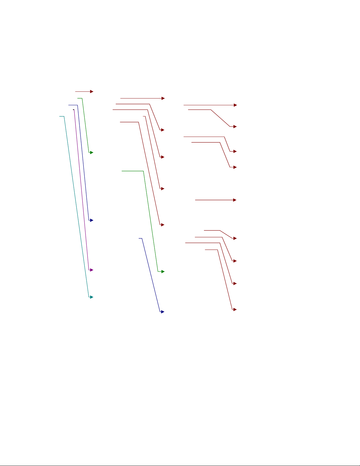
CRS-400 1:8 Redundancy Switch Revision 0
Remote Control MN/CRS400.IOM
CRS-400 Menu Tree
SWITCH MODE: "INDEPENDENT"
SELECT:
CONFIGURE
INFORMATION
MONITOR
STORE/LOAD
UTILITY
CONFIGURE:
MANUAL
ACTIVE
AUTO
REMOTE CONTROL
OPTIONS
INFORMATION:
SWITCH ID
SETUP
IF SWITCH
REMOTE CONTROL
MASKS
MONITOR:
STATUS
SWITCH ALARMS
STORED EVENTS
COMM STATE
MANUAL SELECT:
MODS
DEMODS
ACTIVE MODEM SELECT:
MODS
DEMODS
OPERATING MODE:
AUTO ON
AUTO OFF
REM CONTROL:
LOC/REM
SETTINGS:
OPTIONS:
SWITCH MODE
HOLDOFFS
MASKS
RESTORE TIME
MANUAL MOD SELECT:
BRIDGE (MOD NUMBER) or
BACKUP: (MOD NUMBER)
MANUAL DEMOD SELECT:
BRIDGE (DEMOD NUMBER) or
BACKUP: (DEMOD NUMBER)
ACTIVE MODS:
(SELECT ACTIVE MODS)
ACTIVE DEMODS:
(SELECT ACTIVE DEMODS)
SETTINGS:
FORMAT
BAUD
INTERFACE TYPE
ADDRESS
SWITCH MODE:
INDEPENDENT
DEPENDENT
HOLDOFFS:
STORE/LOAD:
STORE
LOAD
UTILITY:
REAL-TIME CLOCK
EDIT SWITCH ID
DISPLAY BRIGHTNESS
POLLING ON/OFF
IF SWITCH:
ABSENT
PRESENT
STORED EVENTS:
VIEW
CLEAR ALL
BACKUP HOLDOFF TIME
RESTORE HOLDOFF TIME
MASKS:
MODEM ALARMS
SWITCH ALARMS
AUDIO
RESTORE TIME:
OFF/ON
TIME SETTING
Figure 3-1 Principle Menus Tree for Independent Mode
40
Page 57

CRS-400 1:8 Redundancy Switch Revision 0
Remote Control MN/CRS400.IOM
CRS-400 Menu Tree
SWITCH MODE: "DEPENDENT"
SELECT:
CONFIGURE
INFORMATION
MONITOR
STORE/LOAD
UTILITY
CONFIGURE:
MANUAL
ACTIVE
AUTO
REMOTE CONTROL
OPTIONS
INFORMATION:
SWITCH ID
SETUP
IF SWITCH
REMOTE CONTROL
MASKS
MONITOR:
STATUS
SWITCH ALARMS
STORED EVENTS
COMM STATE
MANUAL SELECT:
BRIDGE (MODEM NUMBER) or
BACKUP (MODEM NUMBER)
ACTIVE MODEM SELECT:
(SELECT ACTIVE MODEMS)
OPERATING MODE:
AUTO ON
AUTO OFF
REM CONTROL:
LOC/REM
SETTINGS:
OPTIONS:
SWITCH MODE
HOLDOFFS
MASKS
RESTORE TIME
SETTINGS:
FORMAT
BAUD
INTERFACE TYPE
ADDRESS
SWITCH MODE:
INDEPENDENT
DEPENDENT
HOLDOFFS:
STORE/LOAD:
STORE
LOAD
UTILITY:
REAL-TIME CLOCK
EDIT SWITCH ID
DISPLAY BRIGHTNESS
POLLING ON/OFF
IF SWITCH:
ABSENT
PRESENT
STORED EVENTS:
VIEW
CLEAR ALL
BACKUP HOLDOFF TIME
RESTORE HOLDOFF TIME
MASKS:
MODEM ALARMS
SWITCH ALARMS
AUDIO
RESTORE TIME:
OFF/ON
TIME SETTING
Figure 3-2 Principle Menus Tree for Dependent Mode
41
Page 58

CRS-400 1:8 Redundancy Switch Revision 0
Remote Control MN/CRS400.IOM
3.5 F
The CRS-400 uses “flash memory” technology internally, so that new firmware can be
uploaded to the unit from an external Personal Computer (PC). Flash upgrading makes
software updates and new feature additions very simple, and allows updates to be
delivered via the Internet, E-mail, or on diskette. It is not necessary to open the unit to
perform the upgrade. Simply connect the switch to the serial port of a computer and
execute a software utility.
The cable to connect the PC to the switch is the same as is used for normal EIA-232
remote control, and consists of 3 wires between 9-pin D type female connectors. See
Chapter 2 for pinout details and an illustration of this cable.
Comtech EF Data distributes the free software utility named CCCFLASH.EXE. It is
designed to run under Windows™ 3.1x, Windows 95/98 or Windows NT. This is the
same program used to flash upgrade the CDM-550T modem. The latest switch firmware
file (for example, 400V102.CCC) is distributed with the flash upgrade utility.
3.5.2 F
1
LASH UPGRADING
LASH UPGRADE PROCEDURE
Copy both the utility (CCCFLASH.EXE) and the new firmware file to the same subdirectory
(folder) on the computer’s hard disk. Do not use the root directory.
2
3
4
Note
5
3.5.3 F
Full on-line help is provided with CCCFLASH.EXE. Please contact Comtech EF Data
Customer Support if you have questions, or for additional assistance.
Connect the switch remote control port to an EIA-232 serial port on the PC.
Execute the CCCFLASH.EXE utility.
Follow the instructions presented on the screen, and the upload will take place automatically.
After the successful upload process, the unit automatically re-starts, running the new version
of firmware.
: During this process, the non-volatile RAM that stores the configuration of the switch
is erased.
Re-enter the desired configur atio n parameters.
LASH UPGRADE HELP
42
Page 59

CRS-400 1:8 Redundancy Switch Revision 0
Remote Control MN/CRS400.IOM
Appendix A. FRONT PANEL OPERATION
DETAILS
OPENING SCREEN
SELECT
CONFIG
INFO (Information)
MONITOR
STORE/LD (Store or Load Configuration)
UTIL (Utility)
A.1 OPENING SCREEN
This screen is displayed whenever power is first applied to the unit:
COMTECH CRS-400 SWITCH
SN 123456789 VER 1.01
Press any key to go to the top level selection screen:
SELECT: CONFIG INFO
MONITOR STORE/LD UTIL
43
43
44
51
53
55
57
A.2 SELECT
The following choices are presented:
CONFIG
(Configuration)
INFO
(Information)
MONITOR
(Monitor)
STORE/LD
(Store/Load)
UTIL
(Utility)
43
This menu branch permits the user to fully configure the switch.
This menu branch permits the user to view information on the switch,
without having to go into configuration screens.
This menu branch permits the user to monitor the current status of the
switch and view the log of stored events for both the switch and its attached
modems.
This menu branch permits the user to store and to retrieve up to 10 different
switch configurations.
This menu branch permits the user to perform miscellaneous functions,
such as setting the Real-time clock, adjusting the display brightness, etc.
Page 60

CRS-400 1:8 Redundancy Switch Revision 0
Remote Control MN/CRS400.IOM
A.3 CONFIG
CONFIG: MANUAL AUTO[OFF]
ACTIVE REMCONT OPTIONS
The sub-branches available are:
MANUAL - allows manual control of the bridge/backup of each active mod/demod.
ACTIVE - allows selection of the active mods/demods, or modems.
AUTO[ON] - allows auto mode to be turned on or off (off = manual mode). The currently
selected state is always shown on this menu
REMOTE - defines the remote control settings.
OPTIONS - sets several operating parameters of the switch that pertain to enabling or
disabling the availability of traffic mods/demods, the reporting of faults and time
delays for responding to faults.
The switch may be monitored over the remote control bus at any time.
When in Local mode, however, configuration parameters may only be
changed through the front panel. Conversely, when in Remote mode, the
IMPORTANT
unit may be monitored from the front panel, and configuration parameters
may only be changed via remote control.
A.3.1 (CONFIG) MANUAL
MANUAL SELECT:
BRIDGE:02 BACKUP:02
Use the LEFT/RIGHT keys to select whether to bridge or backup, then use the
UP/DOWN keys to scroll through the mod/demod numbers until the desired number is
displayed. Press ENTER.
Manual Mode: Both these selections are available when the switch is in Manual mode
(Auto is OFF). Numbers for active traffic units are displayed during scrolling, inactive
units are skipped.
Auto Mode: In Auto mode, the switch controls the backup function, based on its fault
relay activity. Therefore, the BACKUP selection is unavailable. This screen is not
available if the switch is currently in Auto Mode AND is backing up a traffic
mod/demod.
While the redundant is backing up a traffic unit, and the user, in Manual mode,
commands the redundant to change from backup to bridging, an option is shown for
using the configuration of the redundant unit to program the offline traffic unit, if desired.
44
Page 61

CRS-400 1:8 Redundancy Switch Revision 0
Remote Control MN/CRS400.IOM
A.3.2 (CONFIG) AUTO[OFF
OPERATING MODE:
AUTO-OFF AUTO-ON (ENTER)
Use this option to turn Auto mode OFF or ON. When Auto Mode is OFF, the switch is
said to be in Manual mode, and the following conditions apply:
The switch does not respond automatically to any mod/demod faults. It simply
performs whatever manual setting was selected on the previous menu.
The STORED EVENT indicator blinks to alert the user that automatic switching will
not occur.
If Dependent, the mods/demods are activated as a pair.
If Independent, the mods and demods are each activated separately, as required.
A.3.3 (CONFIG) ACTIVE
ACTIVE MODEMS: (ENTER)
1 2 3 - 5 6 - 8
A TMI must be present in order for a mod/demod to be activated. A “-“ (hyphen)
indicates an inactive unit. Move the cursor left/right to the desired unit and press the UP
key. The unit number will show in that position. Press ENTER. Similarly, press DOWN
to deactivate a unit.
OR
ON]
A.3.4 (CONFIG) REMOTE CONTROL
SELECT REMOTE CONTROL:
LOC/REM SETTINGS (ENT)
Select LOC/REM or SETTINGS using the LEFT/RIGHT arrow keys, then press ENTER.
A.3.4.1 (CONFIG, REM CONTROL) LOC/REM
SELECT REMOTE CONTROL:
LOCAL REMOTE (PRESS ENT)
If LOCAL is selected, remote control is disabled, but remote monitoring is still possible,
so the remote control settings are displayed.
If REMOTE is selected, then remote control is enabled, and the remote control settings
are available.
45
Page 62

CRS-400 1:8 Redundancy Switch Revision 0
Remote Control MN/CRS400.IOM
A.3.4.2 (CONFIG, REM CONTROL) SETTINGS
REMOTE CONTROL: FORMAT
BAUD TYPE ADDRESS (ENT)
Because remote monitoring is available at all times, the remote control settings may be
set without the need to be in REMOTE mode.
Select FORMAT, BAUD, TYPE, or ADDRESS using the LEFT/RIGHT arrow keys,
then press ENTER.
A.3.4.2.1 (CONFIG, REM, SETTINGS) FORMAT
SELECT DATA FORMAT:
8-N-1 7-E-2 7-O-2 (ENT)
Select the data format for the remote control using the RIGHT/LEFT arrow keys, and
press ENTER. Possible format choices are listed below:
8-N-1
7-E-2
7-O-2
= 8 data bits No parity 1 stop bit
= 7 data bits Even parity 2 stop bits
= 7 data bits Odd parity 2 stop bits
A.3.4.2.2 (CONFIG, REM, SETTINGS) BAUD
EDIT SWITCH BAUDRATE:
19200 BAUD (PRESS ENTER)
Edit the baud rate of the remote control bus connected locally to the M&C computer.
Change the value using the UP/DOWN arrow keys, and press ENTER.
Possible Baud Values:
300 1200 2400 4800 9600 19200
A.3.4.2.3 (CONFIG, REM, SETTINGS) TYPE
INTERFACE TYPE: RS232
RS485-2W RS485-4W (ENT)
Select RS232, RS485 (2-wire), or RS485 (4-wire). Use the LEFT/RIGHT arrow keys to
select an interface type, then press ENTER.
: RS-485 2-wire is available, but not preferred.
Note
In RS232 mode the bus address is fixed at 0, and the following screen is displayed:
46
Page 63

CRS-400 1:8 Redundancy Switch Revision 0
Remote Control MN/CRS400.IOM
A.3.4.2.3.1 (CONFIG, REM, SETTINGS, TYPE) RS232
IN RS232 MODE THE BUS
ADDRESS IS FIXED AT 0000
However, if either RS485 mode is selected, you may edit the bus address:
A.3.4.2.3.2 (CONFIG, REM, SETTINGS, TYPE) RS485
EDIT SWITCH BUS ADDRESS:
3000 (PRESS ENTER)
To edit the RS485 bus address of this unit:
1
Change the value of the address using the UP/DOWN arrow keys.
2
Press ENTER.
The only permitted addresses are:
1000 2000 3000 4000 5000 6000 7000 8000 9000
A.3.5 (CONFIG) OPTIONS
OPTIONS: MASKS MODE[IND]
HOLDOFFS RESTORE-TIME
Use OPTIONS to select mode and masks, affecting how the switch will react to various
faults.
A.3.5.1 (CONFIG, OPTS) MASKS
ALARM MASK: MODEM-ALARMS
SW-ALARMS AUDIO (ENTER)
The switch logs and reacts to its own faults and mod/demod faults. Use this sub-menu to
mask any of these fault types, and to enable or disable an audible indicator (buzzer).
A.3.5.1.1 (CONFIG, OPTS, MASKS) MODEM ALARMS
MODEM ALARM MASK: NONE
MOD DMD BOTH (ENTER)
Use this option to mask traffic faults for MOD (Tx), DMD (Rx), or BOTH, so that the
switch will not react to them. Select one of the four options: NONE, MOD, DMD, or
BOTH.
47
Page 64

CRS-400 1:8 Redundancy Switch Revision 0
Remote Control MN/CRS400.IOM
Masking faults will prevent the switch from performing Auto mode functions when these
mod/demod faults are sensed, and it keeps the faults from being logged by the switch.
Unmasked mod/demod faults are logged in the switch events log for activated units.
A.3.5.1.2 (CONFIG, OPTS, MASKS) SWITCH ALARMS
SWITCH ALARM MASK: NONE
Å PSU-A PSU-B Æ (ENTER)
To have the switch ignore an out-of-range voltage output condition for one of the power
supplies, use this option. Only one of the units can be masked at a time.
Normally, this mask is useful for operating with only one power supply, or if a supply
must be removed for service or replacement.
A.3.5.1.3 (CONFIG, OPTS, MASKS) AUDIO
AUDIO MASK: NONE SW-ALMS
MODEM-ALMS BOTH (ENTER)
This options controls which, if any, alarm types should cause an audible alarm (buzzer) to
sound when the switch detects the alarm condition. This option can be set for unmasked,
or switch and/or mod/demod alarms.
The buzzer is located behind the front panel. In addition, a relay closure to ground
activates on pin 20 of the System Alarms connector, so that other indicators can be
attached to the audible alarm.
A.3.5.2 (CONFIG, OPTS) SWITCH MODE
SELECT SWITCH MODE:
DEPENDENT INDEPENDENT
With the DEPENDENT mode setting, the switch will back up a faulted modulator or
demodulator with both the redundant modulator and demodulator.
With the INDEPENDENT mode setting enabled, the switch will back up a faulted
modulator only with the redundant modulator, or backup a faulted demodulator only with
the redundant demodulator.
48
Page 65

CRS-400 1:8 Redundancy Switch Revision 0
Remote Control MN/CRS400.IOM
A.3.5.3 (CONFIG, OPTS) HOLDOFFS
BACKUP HOLDOFF SEC: 05
RESTORE HOLDOFF SEC: 10
Use HOLDOFFS to set the holdoffs, or delay times, between the switch’s modem alarm
detection and its reactions to the alarm. Both holdoffs can be set from 2 to 99 seconds.
Holdoffs are only applicable when the switch is in Auto mode.
Note:
Backup
Holdoff
Restore
Holdoff
When an active mod/demod exhibits an unmasked fault, the switch bridges it
with the redundant unit and checks that the latter is not also faulted. If no
fault is detected in the redundant unit, the Backup Holdoff determines how
long the switch will wait before performing the actual backup, or switchover
of traffic, to the redundant mod/demod.
The switch continues to back up a faulted traffic mod/demod even after the
fault clears, unless another active mod/demod becomes faulted. In this case,
the Restore Holdoff is the length of time that the originally faulted
mod/demod must stay unfaulted before the switch will automatically put it
back online so that the redundant mod/demod is available to bridge the newly
faulted mod/demod.
49
Page 66

CRS-400 1:8 Redundancy Switch Revision 0
Remote Control MN/CRS400.IOM
A.3.5.4 (CONFIG, OPTS) RESTORE-TIME
RESTORE TIME: [OFF]
OFF/ON SET-TIME (ENT)
RESTORE TIME: [24hr clk]
02:10 (PRESS ENTER)
: The RESTORE feature is only active in Auto mode.
Note
If the switch is set for Auto mode and a sustained fault occurs, it will switch to back-up
and stay there until any further fault occurs, or the user intervenes (taking the switches to
Manual and then selecting to switch from backing up to bridging a unit).
Enabling the RESTORE TIME setting allows the switch to automatically restore
operation from backup to the main traffic unit at a selected time, if all the faults are
cleared.
Select OFF to disable or ON to enable the RESTORE TIME feature and press ENTER. If
RESTORE TIME is ON, set the time (using the 24-hour clock) when the automatic
restoral should occur, and press ENTER.
: Set the RESTORE TIME for a time when traffic is low; for example, 2:00 a.m.
Note
If enabled, and in Auto mode, at the RESTORE TIME, the offline traffic unit is
configured to match the configuration of the redundant unit. This is done in case the unit
has come back from repair. It has been activated, but the user may not know the correct
configuration. It is then checked to see that there are no faults. If there are no faults, the
unit is brought online, freeing up the redundant unit.
50
Page 67

CRS-400 1:8 Redundancy Switch Revision 0
Remote Control MN/CRS400.IOM
A.4 INFO (I
INFO: SWITCH-ID SETUP
IF-SWITCH REMCONT MASK
NFORMATION
Select an INFO parameter to view, using the LEFT/RIGHT keys, then press ENTER.
INFO screens display information on the current configuration of the switch without
risking inadvertent changes.
A.4.1 (INFO) SWITCH-ID
SWITCH ID:
THIS IS A TEST MESSAGE
This displays the user-defined Switch ID string, which is entered via the UTILITY,
SWITCH-ID screen. To return to the previous menu, press ENTER or CLEAR.
A.4.2 (INFO) SETUP
MOD:123---78 DE:12-------8
AUTO:OFF BH:05 RH:20 IND
)
The information on this screen reflects some of the settings configured in the CONFIG,
OPTIONS menu. Active traffic mods/demods are listed on the top line, while Auto mode,
times for Backup Holdoff and Restore Holdoff, and Independent or Dependent mode are
listed on the bottom line.
A.4.3 (INFO) IF-SWITCH
IF-SWITCH IS ABSENT
Or
IF-SWITCH IS PRESENT
This screen shows whether an IF Transponder Switch is connected to the CRS-400 1:8
Redundancy Switch. When an IF switch is present, the CRS-400 does not exert transmit
IF control for an offline mod, the IF switch manages that. There are two models of IF
switch: CRS-280 (70/140) and CRS-282 (L-band).
51
Page 68

CRS-400 1:8 Redundancy Switch Revision 0
Remote Control MN/CRS400.IOM
A.4.4 (INFO) REMCONT (R
REM CNTL: REMOTE RS485-4W
ADDRESS: 5000 19200 8N1
This screen shows whether the unit is in LOCAL or REMOTE mode, and gives details of
the interface type selected, the switch address, the baud rate and character format. Press
ENTER or CLEAR to return to the previous menu.
A.4.5 (INFO) MASKS (A
ALARMS MASKED:
MOD DMD Å PSU-A PSU-B Æ
This screen shows which alarms are currently masked. If an alarm is not masked, a blank
is displayed in the relevant screen position. Power Supplies A and B cannot be masked at
the same time, but are shown together here to indicate their relative positions.
LARM MASK INFO
EMOTE CONTROL INFO
)
)
52
Page 69

CRS-400 1:8 Redundancy Switch Revision 0
Remote Control MN/CRS400.IOM
A.5 MONITOR
MONITOR: STATUS SW-ALARM
STORED-EVENTS COMM-STATE
Select a parameter to monitor using the LEFT/RIGHT arrow keys, then press ENTER.
A.5.1 (MONITOR) STATUS
RM BRIDGING MOD:1 BH:05s
RD BRIDGING DMD:4 BH:05s
This screen shows the current status of the switch.
When the redundant mod/demod is not backing up any of the traffic mods/demods, the
display shows which TM is currently being bridged by the RM. If Auto mode is on, it
will also show the backup holdoff time should the bridged TM fail. If Auto mode is off,
Backup Holdoff (BH) displays “OFF”.
When the switch has taken the bridged TM offline and replaced it with the RM (whether
manually or automatically), the screen changes as shown below:
RM BACKG UP MOD:1 RH:05s
RD BACKG UP DMD:4 RH:05s
Note that the Restore Holdoff (RH) times are shown.
A.5.2 (MONITOR) SWI T CH ALARMS
SWITCH ALARM: MOD I/O
PROBLEM
or
SWITCH ALARM: DEMOD I/O
PROBLEM
(or power supply fault)
To decode an I/O fault, go to MONITOR: COMM-STATE.
53
Page 70

CRS-400 1:8 Redundancy Switch Revision 0
Remote Control MN/CRS400.IOM
A.5.3 (MONITOR) STORED EVENTS
STORED EVENTS: VIEW
CLEAR-ALL (PRESS ENTER)
Select VIEW or CLEAR ALL, using the LEFT/RIGHT arrow keys, then press ENTER.
CLEAR ALL does not prompt for confirmation–the command acts immediately.
A.5.3.1 (MONITOR, STORED-EVENTS) VIEW
LOG23: 26/01/00 10:37:32
FT-06 DMD ALARM (UP/DN)
Use the UP/DOWN arrow keys to scroll backwards or forwards through the entries in the
event log. To return to the previous menu, press ENTER or CLEAR.
The event log can store up to 98 events. When a fault condition occurs, it is time-stamped
and put into the log. Next to the FT (for fault) indicator is either the TM number, RM
(redundant mod/demod fault) or SW (switch fault). Similarly, when the fault condition
clears, this is also recorded, as shown below:
LOG23: 26/01/00 10:37:35
OK-06 DMD ALARM (UP/DN)
To clear the Event Log, select CLEAR-ALL. The previous menu returns.
However, if there are faults present on the unit at this time, they will be re-time-stamped,
and new log entries will be generated.
Note:
In accordance with international convention, the date is shown in DAY-MONTH-YEAR
format.
A.5.4 (MONITOR) COMM-STATE (C
COMMS OK: MOD:1234-!--R
DMD:--345678R
This screen indicates which mods/demods have good EIA-485 I/O communications with
the switch.
An exclamation mark (!), if present, indicates the position of an I/O communications
problem. This is a position that has been activated, but a unit is not responding:
Check the bus address and communications settings
OMMUNICATIONS
)
Check that the bus cable is properly attached.
54
Page 71

CRS-400 1:8 Redundancy Switch Revision 0
Remote Control MN/CRS400.IOM
A.6 STORE/LD (S
STORE/LOAD CONFIG:
STORE LOAD (PRESS ENTER)
TORE OR LOAD CONFIGURATION
Select STORE or LOAD using the LEFT/RIGHT arrow keys, then press ENTER.
The switch can store up to 10 different switch configurations in non-volatile memory.
These are configurations for the switch itself, not the modems attached to it. Switch
configurations contain the information for active units, bridge/backup units, backup
holdoff, restore holdoff, etc. For more information, see the Switch Global Configuration
remote command in Section B.6, Remote Control Commands.
A.6.1 (STORE/LD) STORE
STORE CONFIGURATION TO
LOCATION: 10 (ENTER)
Select the location to store the current configuration to, using the UP/DOWN arrow keys,
then press ENTER.
Available Locations:
)
1 2 3 4 5 6 7 8 9 10
If the selected location does not contain a previously stored configuration, the following
screen is displayed:
YOUR CONFIGURATION HAS
BEEN STORED! (ENTER)
To return to the previous menu, press ENTER or CLEAR.
If, however, the selected location contains a previously stored configuration, the
following screen is displayed:
WARNING! LOC 10 CONTAINS
DATA. OVERWRITE? NO YES
Select NO or YES using the LEFT/RIGHT arrow keys, then press ENTER.
Selecting YES will overwrite the existing configuration at the selected location.
55
Page 72

CRS-400 1:8 Redundancy Switch Revision 0
Remote Control MN/CRS400.IOM
A.6.2 (STORE/LD) LOAD
LOAD CONFIGURATION FROM
LOCATION: 10 (ENTER)
Select the location to load a configuration from, using the UP/DOWN arrow keys, then
press ENTER.
Available Locations:
1 2 3 4 5 6 7 8 9 10
If the selected location contains valid data, the following screen will be displayed:
THE NEW CONFIGURATION
HAS BEEN LOADED (ENTER)
To return to the previous menu, press ENTER or CLEAR.
If, however, the selected location does not contain valid data, the following screen will be
displayed:
WARNING! LOC 10 CONTAINS
NO DATA! (ENTER)
To return to the previous menu, press ENTER or CLEAR.
56
Page 73

CRS-400 1:8 Redundancy Switch Revision 0
Remote Control MN/CRS400.IOM
A.7 UTIL (U
UTILITY: CLOCK SWITCH-ID
DISPLAY POLLING (ENTER)
TILITY
)
Select a parameter using the LEFT/RIGHT arrow keys, then press ENTER.
Use this sub-menu to select from a number of different utility functions, which are
described in the following paragraphs.
A.7.1 (UTILITY) CLOCK (S
EDIT REAL TIME CLOCK:
12:00:00 24/04/00 (ENT)
To edit the time and date settings of the real-time clock:
1
Select the digit to be edited using the LEFT/RIGHT arrow keys.
2
Change the value of the digit using the UP/DOWN arrow keys.
3
Press ENTER.
: In accordance with international convention, the date is shown in DAY-MONTH-YEAR
Note
format.
ET REAL-TIME CLOCK
)
A.7.2 (UTILITY) SWITCH-ID
EDIT SWITCH ID: (ENTER)
---- THIS IS A TEST ----
To edit the Switch ID string:
1
Use the Left/Right arrow to select a character position on the bottom line.
2
Use the Up/Down arrows to edit the selected character.
3
Once the string edits are finished, press ENTER.
Only the bottom line is available (24 characters).
Note:
Available Characters:
( ) * + - , . / space
0 1 2 3 4 5 6 7 8 9
A B C D E F G H I J K L M
N O P Q R S T U V W X Y Z
57
Page 74

CRS-400 1:8 Redundancy Switch Revision 0
Remote Control MN/CRS400.IOM
A.7.3 (UTILITY) DISPLAY (D
EDIT DISPLAY BRIGHTNESS:
100% (PRESS ENTER)
To edit the display brightness, use the UP/DOWN arrow keys. Press ENTER when the
brightness is suitable.
A.7.4 (UTILITY) POLLING
POLLING: SUSPEND RESUME
WILL RESUME IN 91 SEC
The switch is continually polling units via the EIA-485 bus. To temporarily suspend
polling (example: for viewing a redundant unit configuration via the front panel), use the
RIGHT/LEFT arrow keys to select SUSPEND, and press ENTER. The second line of the
display shows the number of seconds remaining (counting down from 99) before polling
will automatically resume.
To resume polling immediately, use the RIGHT/LEFT arrow keys to select RESUME,
and press ENTER.
ISPLAY BRIGHTNESS
)
58
Page 75

Appendix B. REMOTE CONTROL
Introduction
EIA-485
EIA-232
Basic Protocol
Packet Structure
Remote Control Commands
B.1 I
NTRODUCTION
This section describes the protocol and message command set for remote monitor and
control of the CRS-400 Redundancy Switch.
The electrical interface is either an EIA-485 multi-drop bus (for the control of many
devices) or an EIA-232 connection (for the control of a single device), and data is
transmitted in asynchronous serial form, using ASCII characters. Control and status
information is transmitted in packets, of variable length, in accordance with the structure
and protocol defined in later sections.
59
59
60
60
61
66
B.2 EIA-485
For applications where multiple devices are to be monitored and controlled, a full-duplex
(or 4-wire plus ground) EIA-485 is required. Half-duplex (2-wire plus ground) EIA-485
is possible, but is not preferred.
In full-duplex EIA-485 communication there are two separate, isolated, independent,
differential-mode twisted pairs, each handling serial data in different directions. It is
assumed that there is a ‘controller’ device (a PC or dumb terminal), that transmits data, in
a broadcast mode, via one of the pairs. Many ‘target’ devices are connected to this pair,
that all simultaneously receive data from the controller. The controller is the only device
with a line-driver connected to this pair - the target devices only have line-receivers
connected.
59
Page 76

CRS-400 1:8 Redundancy Switch Revision 0
Remote Control MN/CRS400.IOM
In the other direction, on the other pair, each target has a tri-stateable line driver
connected, and the controller has a line-receiver connected. All the line drivers are held in
high-impedance mode until one (and only one) target transmits back to the controller.
Each target has a unique address, and each time the controller transmits, in a framed
‘packet’ of data, the address of the intended recipient target is included. All of the targets
receive the packet, but only one (the intended) will reply. The target enables its output
line driver, and transmits its return data packet back to the controller, in the other
direction, on the physically separate pair.
EIA- 485 (full duplex) summary:
Two differential pairs - one pair for controller to target, one pair for target to
controller.
Controller-to-target pair has one line driver (controller), and all targets have line-
receivers.
Target-to-controller pair has one line receiver (controller), and all targets have tri-
state drivers.
B.3 EIA-232
This is a much simpler configuration in which the controller device is connected directly
to the target via a two-wire-plus-ground connection. Controller-to-target data is carried,
via EIA-232 electrical levels, on one conductor, and target-to-controller data is carried in
the other direction on the other conductor.
B.4 B
ASIC PROTOCOL
Whether in EIA-232 or EIA-485 mode, all data is transmitted as asynchronous serial
characters, suitable for transmission and reception by a UART. The asynchronous
character format may be:
8-N-1 8 data bits, no parity, 1 stop bit
7-E-2 7 data bits, even parity, 2 stop bits
7-O-2 8 data bits, odd parity, 2 stop bits.
The selectable baud rates are 300, 1200, 2400, 4800, 9600 and 19,200 baud.
60
Page 77

CRS-400 1:8 Redundancy Switch Revision 0
Remote Control MN/CRS400.IOM
All data is transmitted in framed packets. The controller is assumed to be a PC or ASCII
dumb terminal, that is in charge of the process of monitor and control. The controller is
the only device that is permitted to initiate, at will, the transmission of data. Targets are
only permitted to transmit when they have been specifically instructed to do so by the
controller.
All bytes within a packet are printable ASCII characters, less than ASCII code 127. In
this context, the Carriage Return and Line Feed characters are considered printable.
All messages from controller to target require a response (with one exception). This will
be either to return data that has been requested by the controller, or to acknowledge
reception of an instruction to change the configuration of the target. The exception to this
is when the controller uses Address 0 (universal address) in EIA-485 mode. In this case,
the target does not respond.
B.5 P
Character
Number of
Characters
ACKET STRUCTURE
Controller-to-target:
Start
ASCII
Code
of
Packet
< / = or ?
60 47 61 or 63 13
1 4 1 3 1 n 1
Target
Address
Address
Delimiter
Instruction
Example: <0000/RSH=30{CR}
Code
Code
Qualifier
Optional
Arguments
End of
Packet
Carriage
Return
61
Page 78

CRS-400 1:8 Redundancy Switch Revision 0
Remote Control MN/CRS400.IOM
Target-to-controller:
Start
Character
of
Packet
< /
Target
Address
Address
Delimiter
Instruction
Code
Code
Qualifier
=, ?, !
or *
Optional
Arguments
End of
Packet
Carriage
Return
Line
Feed
ASCII
Code
Number of
Characters
Example: >0000/OPM=1{CR}{LF}
B.5.1 S
Controller to Target: This is the character ‘<’ (ASCII code 61)
Target to Controller: This is the character ‘>’ (ASCII code 62)
Because this is used to provide a reliable indication of the start of packet, these two
characters may not appear anywhere else within the body of the message.
B.5.2 A
While up to 9,999 devices can be uniquely addressed via an EIA-485 bus, the 1:N
Redundancy Switch imposes some addressing specifications. The Switch address is x000:
60 47
1 4 1 3 1 From 0 to n 2
TART OF PACKET
DDRESS
61, 63,
33 or 42
3, 10
In EIA-232 applications the switch address is fixed at 0000.
In EIA-485 applications, the switch address may be set to 1000, 2000, 3000, 4000, 5000,
6000, 7000, 8000, or 9000. Up to nine switches may be connected on the same bus.
The addresses of the modulators and/or demodulators that may be attached to the Switch
must each have its addresses set correctly, according to the Switch address and the unit’s
position in the Switch set-up:
x001 for Traffic Mod #1 x011 for Traffic Demod #1
x002 for TM #2 and on up to x012 for TD #2 and on up to
x008 for TM #8 and x018 for TD#8 and
x009 for the Redundant Mod x019 for the Redundant Demod
62
Page 79

CRS-400 1:8 Redundancy Switch Revision 0
Remote Control MN/CRS400.IOM
Remote monitor and control of units attached to the Switch is available, transparently via
the Switch, to any devices with addresses x001 through x099, attached to the auxiliary
EIA-485 link. The command protocol of the messages is dictated by the device being
addressed.
Note that in either EIA-232 or EIA-485 mode, the auxiliary link from the switch to all
the modems is fixed at EIA-485, 8-N-1, 19200 baud (multidrop).
The modem addresses (001-019) must be set on each mod/demod, via the front panel.
Example: To send a message to TM# 1 (front panel address set to 001) attached to the
multidrop cable of switch (address 5000), the controller sends a message using address,
5001, and the responses from the modulator (via the switch) will indicate address 5001.
B.5.3 I
B.5.4 I
NSTRUCTION CODE
This is a three-character alphabetic sequence that identifies the subject of the message.
Wherever possible, the instruction codes have been chosen to have some significance.
For example, OPM is for OPerating Mode, BKH is for BacKup Holdoff, etc. This aids in
the readability of the message if seen in its raw ASCII form. Only upper case alphabetic
characters may be used (A-Z, ASCII codes 65 - 90).
NSTRUCTION CODE QUALIFIER
This is a single character that further qualifies the preceding instruction code. Code
Qualifiers obey the following rules:
1) From Controller to Target, the only permitted values are:
= (ASCII code 61)
? (ASCII code 63)
They have these meanings:
The ‘=’ code (controller to target) is used as the assignment operator, and is used to
indicate that the parameter defined by the preceding byte should be set to the value of the
argument(s) that follow it. For example, in a message from controller to target, OPM=1
would mean ‘set the OPerating Mode to Auto’
The ‘?’ code (controller to target) is used as the query operator, and is used to indicate
that the target should return the current value of the parameter defined by the preceding
byte. For example, in a message from controller to target, OPM? would mean ‘what is the
current Operating Mode?’
63
Page 80

CRS-400 1:8 Redundancy Switch Revision 0
Remote Control MN/CRS400.IOM
2) From Target to Controller, the only permitted values are:
= (ASCII code 61)
? (ASCII code 63)
! (ASCII code 33)
* (ASCII code 42)
# (ASCII code 35)
They have these meanings:
The = code (target to controller) is used in two ways:
First, if the controller has sent a query code to a target (for example OPM?,
meaning ‘what is the Operating Mode?’), the target would respond with OPM=x,
where x is 0 representing Manual mode or 1 representing Auto mode.
Second, if the controller sends an instruction to set a parameter to a particular
value, then, providing the value sent in the argument is valid, the target will
acknowledge the message by replying with OPM= (with no message arguments).
The ? code (target to controller) is only used as follows:
If the controller sends a correctly formatted instruction to set a parameter, but
using an invalid argument, then the target will acknowledge the message by
replying (for example) with OPM? (with no message arguments).
The * code (target to controller) is only used as follows:
If the controller sends a correctly formatted instruction, but the unit cannot
implement at this time, the target will acknowledge the message by replying (for
example) with OPM* (with no message arguments).
The # code (target to controller) is only used as follows:
If the controller sends a correctly formatted instruction, but the unit is not in
Remote Mode, the target will acknowledge the message by replying (for
example) with OPM# (with no message arguments).
64
Page 81

CRS-400 1:8 Redundancy Switch Revision 0
Remote Control MN/CRS400.IOM
The ! code (target to controller) is only used as follows:
If the controller sends an instruction code that the target does not recognize, the
target will acknowledge the message by echoing the invalid instruction,
followed by the ! character with. Example: XYZ!
B.5.5 M
Arguments are not required for all messages. Arguments are ASCII codes for the
characters 0 to 9 (ASCII 48 to 57), A to Z (ASCII 65 to 90), period (ASCII 46) and
comma (ASCII 44).
B.5.6 E
Controller to Target: This is the ‘Carriage Return’ character (ASCII code 13)
Target to Controller: This is the two-character sequence ‘Carriage Return’, ‘Line Feed’.
(ASCII codes 13 and 10).
Both indicate the valid termination of a packet.
ESSAGE ARGUMENTS
ND OF PACKET
65
Page 82

CRS-400 1:8 Redundancy Switch Revision 0
Remote Control MN/CRS400.IOM
B.6 R
EMOTE CONTROL COMMANDS
Parameter
Type
Local/ Remote
Status
Equipment ID n.a. 4 bytes,
Switch ID
string
Operating
Mode
Switching
Mode
Active Mods ACM= 8 bytes,
Command
(controller
to target)
LRS= 1 byte,
SID= 24 bytes,
OPM= 1 byte,
SWM= 1 byte,
Argument
count
numerical,
0 or 1
ASCII
ASCII
numerical,
0 or 1
numerical,
0 or 1
numerical
Description of arg uments
Note: All arguments are ASCII numeric codes between 48
and 57.
Command or Query
Sets or queries the local/remote status of the Switch:
0 = Local
1 = Remote
Query only.
Switch returns information concerning the equipment
identification, with only a base switch “S400” currently in
use.
Command or Query.
Sets or queries the user-defined Switch ID string, which
is a fixed length of 24 characters.
Valid characters include:
Space ( ) * + - , . / 0-9 and A-Z.
Command or Query.
Sets the operating mode:
0 = manual mode
1 = auto mode
Command or Query.
Sets the Switching mode:
0 = Dependent switching – Mods & Demods switched
together
1 = Independent switching – Mods & Demods switched
separately
Note
: can only be changed if the OPM is manual AND
there are no units in back-up. ACM settings may be
affected.
Command or Query.
Sets or queries the active state of all 8 Traffic Mods (or
Mod & Demods, if Dependent):
0 = de-activate Traffic Mod
1 = activate Traffic Mod
Note
: only active units will be monitored by the switch.
Responses
to
Command
(target to
controller)
LRS=
LRS?
LRS#
n.a. EID? EID=xxxx
SID=
SID?
SID#
OPM=
OPM?
OPM*
OPM#
SWM
SWM?
SWM*
SWM#
ACM=
ACM?
ACM*
ACM#
Query
(controller
to target)
LRS? LRS=x
SID? SID=xxxxxxxxxxxxxxxxxxxxxxxx
OPM? OPM=x
SWM? SWM=x
ACM? ACM=xxxxxxxx
Response to Query
(target to controller)
(see description of arguments)
(see description of arguments)
(see description of arguments)
(see description of arguments)
(see description of arguments)
(see description of arguments)
66
Page 83

CRS-400 1:8 Redundancy Switch Revision 0
Remote Control MN/CRS400.IOM
Parameter
Type
Active
Demods
Bridge/Backup
Modulator
Bridge/Backup
Demodulator
Active Mod
Query
Active Demod
Query
Command
(controller
to target)
ACD= 8 bytes,
Argument
count
numerical
Description of arg uments
Note: All arguments are ASCII numeric codes between 48
Command or Query.
Sets or queries the active state of all 8 Traffic Demods:
0 = de-activate Traffic Demod
1 = activate Traffic Demod
Note
Use ACM if in Dependent mode.
BBM= 2 bytes,
numerical
Command or Query.
Sets or queries the bridged/backup state for Mods:
x = 0/1 indicating bridged/backup of Modulator
y = 1-8, the number of Mod that the Redundant Mod is
Note
(see ACM).
BBD= 2 bytes,
numerical
Command or Query.
Sets or queries the bridged/backup state for Demods:
x = 0/1 indicating bridged/backup of Demodulator
y = 1-8, the number of Demod that the Redundant
Demod is tracking.
Note
active (see ACD).
Use BBM if in Dependent mode.
n.a. 8 bytes,
numerical
Query only.
Returns the state of all 8 Traffic Mods, which is usually
as set by ACM, but possibly overruled by Switch
conditions, where x is:
0 = TMI not present (cannot be activated)
1 = TMI present but Mod/Modem not activated
2 = TMI present, Mod activated and responding
3 = TMI present, Mod activated but NOT responding
n.a. 8 bytes,
numerical
Query only.
Returns the state of all 8 Traffic Demods, which is
usually as set by ACD, but possibly overruled by Switch
conditions, where x is:
0 = TMI not present (cannot be activated)
1 = TMI present but Demod not activated
2 = TMI present, Demod activated and responding
3 = TMI present, Demod activated but NOT responding
Use AMQ if in Dependent mode.
and 57.
: only active units will be monitored by the switch.
tracking.
: requires TMIs to be present, & mods to be active
: requires TMIs to be present, & demods to be
Responses
to
Command
(target to
controller)
ACD=
ACD?
Query
(controller
to target)
Response to Query
(target to controller)
ACD? ACD=xxxxxxxx
(see description of arguments)
ACD*
ACD#
BBM=
BBM?
BBM? BBM=xy
(see description of arguments)
BBM*
BBM#
BBD=
BBD?
BBD? BBD=xy
(see description of arguments)
BBD*
BBD#
n.a. AMQ? AMQ=xxxxxxxxy
(see description of arguments)
y indicates the Redundant unit/RMI state, similarly, but activati on is
assumed.
n.a.. ADQ? ADQ=xxxxxxxxy
(see description of arguments)
y indicates the Redundant unit/RMI state, similarly, but activati on is
assumed.
67
Page 84

CRS-400 1:8 Redundancy Switch Revision 0
Remote Control MN/CRS400.IOM
Parameter
Type
Backup
Holdoff Time
Restore
Holdoff Time
Switch Global
Configuration
Modem Alarm
Mask
Switch Alarm
Mask
Command
(controller
to target)
BKH= 2 bytes
Argument
count
numerical,
Description of arg uments
Note: All arguments are ASCII numeric codes between 48
Command or Query.
Sets or queries the backup holdoff delay time, used
when Auto Mode prepares to backup a faulted
Mod/Demod:
xx = 02-99, seconds of delay before online swap
RSH= 2 bytes,
numerical
Command or Query.
Sets or queries the restore holdoff delay time. Used in
Auto Mode.
xx = 02-99 seconds.
This is the time for which an offline Traffic Unit must be
fault-free before it may be put back online if the
Redundant Unit needs to bridge a different newlyfaulted Unit.
SGC= 42 bytes,
numerical
Command or Query.
Global configuration of switch, in the form:
OmmmmmmmmIMMDDbbrrMSAEttttssssssssdddddddd
where:
MAM= 1 byte,
numerical
Command or Query.
Sets or queries the mod/demod alarm mask:
0 = No faults masked
1 = Mod faults masked
2 = Demod faults masked
3 = Both Mod & Demod faults masked
SAM= 1 byte,
numerical
Command or Query.
Sets or queries the modem alarm mask:
0 = No faults masked
1 = PSU A faults masked
2 = PSU B faults masked
and 57.
begins.
O = Operating Mode – same as OPM= (1 bytes)
m = Active Mod/ems – same as ACM= (8 bytes)
I = in/dependent Switching Mode – same as SWM (1 byte)
MM= Bridge/Backup State – same as BBM (2 bytes)
DD= Bridge/Backup State – same as BBD (2 bytes)
bb = Backup Holdoff Time – same as BKH (2 bytes)
rr = Restore Holdoff Time – same as RSH (2 bytes)
M = Modem Alarm Mask – same as MAM (1 byte)
S = Switch Alarm Mask – same as SAM (1 byte)
A = Audio Alarm Mask – same as AAM (1 bytes)
E = Restore Time Enable – same as RTE (1 byte)
tttt – Restore Time - same as RTT ( 4 bytes)
s = spare byte (8 bytes)
d = Active Demods – same as ACD= (8 bytes)
Responses
to
Command
(target to
controller)
BKH=
BKH?
BKH*
BKH#
RSH=
RSH?
RSH*
RSH#
SGC=
SGC?
SGC*
SGC#
MAM=
MAM?
MAM*
MAM#
SAM=
SAM?
SAM*
SAM#
Query
(controller
to target)
Response to Query
(target to controller)
BKH? BKH=xx
(see description of arguments)
RSH? RSH=xx
(see description of arguments)
SGC? SGC=OmmmmmmmmIMMDDbbrrMSAEttttssssssssdddddddd
(see description of arguments)
MAM? MAM=x
(see description of arguments)
SAM? SAM=x
(see description of arguments)
68
Page 85

CRS-400 1:8 Redundancy Switch Revision 0
Remote Control MN/CRS400.IOM
Parameter
Type
Audio Alarm
Mask
Retrieve next
5 unread
Stored Events
Command
(controller
to target)
AAM= 1 byte,
Argument
count
numerical
Description of arg uments
Note: All arguments are ASCII numeric codes between 48
and 57.
Command or Query.
Sets or queries the audio alarm mask:
0 = No faults masked (audio enabled in response to
any fault)
1 = Switch faults masked
2 = Modem faults masked
3 = All faults masked (audio never enabled)
n.a. 79 bytes Query only.
Returns the oldest 5 Stored Events which have not yet
been read over the remote control. Reply format:
{CR}sub-body{CR}sub-body{CR}sub-body{CR}subbody{CR}sub-body, where sub-body =
ABCddmmyyhhmmss
A is the fault indicator:
F = Fault,
C = Clear,
I = Info
B is the faulting/clearing Unit:
1-8 = Mod (1-8)
9 = Redundant Mod
A-H = Demod (1-8)
I = Redundant Demod
J = Switch
K = Power on/off, or log cleared (Info events)
C is the fault code number , as defined:
Switch: 1 through D, the same as FLT? string.
Modem: 0
Info: 0= Power off, 1= Power on, 2= Log cleared.
ddmmyy hhmmss indicates the date & time of the
event.
If there are no new events, the unit replies with RNE? If
fewer than 5 events remain, the last positions are
padded with zeros.
Responses
to
Command
(target to
controller)
AAM=
AAM?
Query
(controller
to target)
Response to Query
(target to controller)
AAM? AAM=x
(see description of arguments)
AAM*
AAM#
n.a. RNE? RNE=[cr]
ABCddmmyyhhmmss[cr]
ABCddmmyyhhmmss[cr]
ABCddmmyyhhmmss[cr]ABCddmmyyhhmmss[cr]ABCddmmyyhhmmss
(see description of arguments)
69
Page 86

CRS-400 1:8 Redundancy Switch Revision 0
Remote Control MN/CRS400.IOM
Parameter
Type
Retrieve
Number of
unread Stored
Events
Command
(controller
to target)
n.a. 2 bytes,
Argument
count
numerical
Description of arg uments
Note: All arguments are ASCII numeric codes between 48
Query only.
Switch returns the number of Stored Events which
remain unread, in the form xx.
Note
: This means unread over the remote control –
viewing the stored events from the front panel of the
modem does not affect this value.
Example: NUE=98
Clear All
Stored Events
CAE= None Command only (takes no arguments ).
Instructs the unit to clear the Stored Events Log.
Serial Number SNO= 9 bytes
numerical
Query only.
(FACTORY USE command)
Unit returns its 9 digit serial number.
Example: SNO=000001765
Software
Revision
n.a. 4 bytes,
numerical
Query only.
Unit returns the value of internal software revision
installed in the unit, in the form x.xx
Example: SWR=1.03 (Ver 1.03)
Restore Time
Enable
RTE= 1 byte,
numerical,
0 or 1
Command or Query.
Effective only in Auto Mode (see OPM)
If there is a unit is back-up mode and Auto-Restore is
enabled:
at the Restore Time, the offline unit will be correctly
configured (if necessary) and if it stays unfaulted, it
will be switched on-line.
Restore Time RTT= 4 bytes,
numerical
Command or Query.
Format is hhmm, using a 24 hour clock.
hh = hours, between 00 and 23, and
mm = minutes, between 00 and 59.
See RTE above for details.
Date DAY= 6 bytes,
numerical
Command or Query.
Format is ddmmyy, where:
dd = day of the month, between 01 and 31,
mm = month of the year, between 01 and 12 and
yy = year, between 97 and 96 (1997 to 2000, then
2000 to 2096)
Example: DAY=240457 represents April 24, 2057
and 57.
Responses
to
Command
(target to
controller)
Query
(controller
to target)
Response to Query
(target to controller)
n.a. NUE? NUE=xx
(see description of arguments)
CAE=
n.a n.a.
CAE?
CAE#
SNO=
SNO?
SNO? SNO=xxxxxxxxx
(see description of arguments)
SNO*
SNO#
n.a. SWR? SWR=x.xx
(see description of arguments)
RTE=
RTE?
RTE? RTE=x
(see description of arguments)
RTE*
RTE#
RTT=
RTT?
RTT? RTT=hhmm
(see description of arguments)
RTT*
RTT#
DAY=
DAY?
DAY? DAY=ddmmyy
(see description of arguments)
DAY*
DAY#
70
Page 87

CRS-400 1:8 Redundancy Switch Revision 0
Remote Control MN/CRS400.IOM
Parameter
Type
Time TIM= 6 bytes,
Command
(controller
to target)
Argument
count
numerical
Description of arg uments
Note: All arguments are ASCII numeric codes between 48
Command or Query.
Format is hhmmss, using a 24 hour clock, where
hh = hours, between 00 and 23,
mm = minutes, between 00 and 59, and
ss = seconds, between 00 and 59
Example: TIM=231259 represents the time 23:12:59.
Config Store CST= 1 byte,
numerical,
0-9
Command or Query.
Forces the unit to store the current modem configuration
in Configuration Memory location defined by the one
byte argument (0 - 9).
Example CST=4 (Store current config into location 4)
WARNING: Use with care! If the location already
contains data, it will be automatically overwritte n. If
in doubt, query the location using CST?x.
Config Load CLD= 1 byte,
numerical,
0-9
Command only.
Forces the switch to retrieve the Configuration Memory
location defined by the one byte argument (0 to 9). and
to re-program the switch with that stored configuration.
WARNING: Use with care! Current configuration
settings will be overwritten. If in doubt, query the
contents of the location using CST?x.
Repeat Last
Message
n.a. n.a. Query only.
Responds with a repeat of the last response message.
Note: this is the one instruction where the response
code does not match the RLM that was sent.
Faults and
Status
n.a. 14 bytes,
numerical
Query only.
Unit returns the current fault and status codes for the
switch itself, where each location in the string is either 0
for no fault or 1 for faulted, and the positions are:
Leftmost 1 = Mod remote comm problem
2 = Demod remote comm problem
3/4 = +5V PSU-A under/over
5/6 = +5V PSU-B under/over
7/8 = +12V PSU-A under/over
9/10 = +12V PSU-B under/over
11/12 = -12V PSU-A under/over
Rightmost 13/14 = -12V PSU-B under/over
and 57.
(use AMQ for detail)
(use ADQ for detail)
Responses
to
Command
(target to
controller)
TIM=
TIM?
Query
(controller
to target)
Response to Query
(target to controller)
TIM? TIM=hhmmss
(see description of arguments)
TIM*
TIM#
CST=
CST?
CST#
CST?x
where x
is 0-9
CST=xxxxx…
where xxxx… is the same format as SGC, or
CST* if no config is stored
CLD=
n.a. n.a..
CLD?
CLD*
CLD#
n.a. RLM? See the section corresponding to the response instruction code
n.a. FLT? FLT=xxxxxxxxxxxxxx
(see description of arguments
71
Page 88

CRS-400 1:8 Redundancy Switch Revision 0
Remote Control MN/CRS400.IOM
72
Page 89

Appendix C. CABLE DRAWINGS
Figure C-1 PC 9-Pin Serial Port to CRS-400 EIA-232 Remote Control Port
Figure C-1 shows the cable required for a simple EIA-232 connection between a PC
serial port and the CRS-400 remote control port. This cable is needed for flash upgrading.
73
Page 90

CRS-400 1:8 Redundancy Switch Revision 0
Cable Drawings MN/CRS400.IOM
Figure C-2 shows the HSSI data cable drawing for connections between the modem and
the switch, and between the user data and the switch.
Figure C-2 HSSI Data Cable
74
Page 91

CRS-400 1:8 Redundancy Switch Revision 0
Cable Drawings MN/CRS400.IOM
Table C-1 CA/WR9189 Cable Assembly (Pinout, Male/Male, HSSI, Shielded)
From To Signal Color Pair From To Signal Color Pair
GND Drain GND Drain
P1-01 P2-01 BLK P1-14 P2-14 GRN
P1-26 P2-26
SIG GND
RED
X
P1-39 P2-39
OPEN
WHT
P1-02 P2-02 BLK P1-15 P2-15 GRN
P1-27 P2-27
RT
WHT
X
P1-40 P2-40
OPEN
BLU
P1-03 P2-03 BLK P1-16 P2-16 GRN
P1-28 P2-28
CA
GRN
X
P1-41 P2-41
OPEN
YEL
P1-04 P2-04 BLK P1-17 P2-17 GRN
P1-29 P2-29
RD
BLU
X
P1-42 P2-42
OPEN
BRN
P1-05 P2-05 BLK P1-18 P2-18 GRN
P1-30 P2-30
OPEN
YEL
X
P1-43 P2-43
OPEN
ORG
P1-06 P2-06 BLK P1-19 P2-19 WHT
P1-31 P2-31
ST
BRN
X
P1-44 P2-44
SIG GND
BLU
P1-07 P2-07 BLK P1-20 P2-20 WHT
P1-32 P2-32
SG
ORG
X
P1-45 P2-45
OPEN
YEL
P1-08 P2-08 RED P1-21 P2-21 WHT
P1-33 P2-33
TA
WHT
X
P1-46 P2-46
OPEN
BRN
P1-09 P2-09 RED P1-22 P2-22 WHT
P1-34 P2-34
TT
GRN
X
P1-47 P2-47
OPEN
ORG
X
X
X
X
X
X
X
X
X
P1-10 P2-10 RED P1-23 P2-23 BLU
P1-35 P2-35
LA
BLU
X
P1-48 P2-48
OPEN
YEL
X
P1-11 P2-11 RED P1-24 P2-24 BLU
P1-36 P2-36
SD
YEL
X
P1-49 P2-49
OPEN
BRN
X
P1-12 P2-12 RED P1-25 P2-25 BLU
P1-37 P2-37
LB
BRN
X
P1-50 P2-50
SIG GND
ORG
X
P1-13 P2-13 RED
P1-38 P2-38
SG
ORG
X
75
Page 92

CRS-400 1:8 Redundancy Switch Revision 0
Cable Drawings MN/CRS400.IOM
76
Page 93

Index
Data Redundancy And Controller, 8
A
Disclaimer, xii
About Rack Support, 15
About this Manual, viii
Activate Desired Traffic Mods/Demods, 29
Address, 27
Alarm Masking, 33
Applying Power to the Switch, 27, 28
Auxiliary Serial Connector/Pass Through,
21
B
Backup Holdoff Operation, 32
C
Cables and Connectors, 15
Cautions and Warnings, viii
CONFIG, 28, 29, 32, 33, 35, 43, 44, 45, 46,
47, 48, 49, 50, 51, 55
Configuring and Cabling for a Single
Transponder, 30
Configuring Automatic Operation Mode, 31,
32
Configuring the IF Carriers, 30
Configuring the Mods/Demods – Firmware
Versions, 27
Configuring the Switch, 28, 29
Connecting the Cables, 26
Conventions and References, viii
CRS-280 IF Redundancy Switch
Specifications, 9
Customer Support, ii, ix, xii, 42
E
EIA-232, ix, 20, 42, 73
EIA-485, ix, 4, 5, 8, 13, 20, 21, 27, 54, 58
EMC Compliance, x
EN 60950, xi, 7
EN50082-1 Compliance, x
EN55022 Compliance, x
Exclusive Remedies, xii
F
Federal Communications Commission
(FCC), x
Flash Upgrade Help, 42
Flash Upgrade Procedure, 42
Flash Upgrading, 42
Front And Rear Panels, 5
Front Panel Display, 35
Front Panel Keys, 37
H
HSSI Cable, 15
HSSI Connection, 26
HSSI Module, 22, 24
I
IF Switch Control Connector, 19
INFO (Information), 51
Installation Details, 15
Introduction, 1
D
Data Connectors, 14
77
LED Indicators, 38
L
Page 94

CRS-400 1:8 Redundancy Switch Revision 0
Index MN/CRS400.IOM
Limitations of Warranty, xii
Low Voltage Directive (LVD), xi
M
Major Assemblies And Options, 6
Menu Trees, 39
Metric Conversion, viii
MONITOR, 29, 30, 43, 53, 54
Mounting Instructions, 14
O
OPENING SCREEN, 43
Outline Drawing, 10
P
Provide Airflow, 14
R
Recommended Standard Designations, ix
Related Documents, viii
Remote Control Commands, 66
Remote Control Connector, 20
Remote Control Connector, 9-Pin D Type
Male, 20
Reporting Comments or Suggestions
Concerning this Manual, ix
Restore Holdoff Operation, 33
RMI Modules, 24
S
Safety Compliance, xi
Set Auto Mode On, 32
Single Power Supply Operation (Test), 28
Specifications (Preliminary), 7
STORE/LD (Store or Load Configuration),
55
System Alarms Connector, 18
T
TMI Data Connector (HSSI), 16
TMI Modules, 22
Trademarks, ix
U
Unpacking and Inspection, 13
UTIL (Utility), 57
V
Verify LED conditions., 29
W
Warranty Policy, ii, xii
78
Page 95

METRIC CONVERSIONS
Units of Length
Unit
1 centimeter — 0.3937 0.03281 0.01094
1 inch 2.540 — 0.08333 0.2778
1 foot 30.480 12.0 — 0.3333
1 yard 91.44 36.0 3.0 —
Centimeter
Inch
Foot
Yard
Mile
6.214 x 10
1.578 x 10
1.893 x 10
5.679 x 10
Meter
-6
-5
-4
-4
0.01 — —
0.254 — 25.4
0.3048 — —
0.9144 — —
Kilometer Millimeter
1 meter 100.0 39.37 3.281 1.094
1 mile
1 mm — 0.03937 — — — — — —
1 kilometer — — — — 0.621 — — —
1.609 x 10
5
6.336 x 10⁴ 5.280 x 10³ 1.760 x 10³
6.214 x 10
-4
—
— — —
1.609 x 10³
1.609 —
Temperature Conversions
Unit
32° Fahrenheit
212° Fahrenheit
-459.6° Fahrenheit
° Fahrenheit
—
—
—
° Centigrade
0
(water freezes)
100
(water boils)
273.1
(absolute 0)
Formulas
C = (F - 32) * 0.555
F = (C * 1.8) + 32
Units of Weight
Unit
1 gram — 0.03527 0.03215 0.002205 0.002679 0.001
Gram
Ounce
Avoirdupois
Ounce
Troy
Pound
Avoir.
Pound
Troy
Kilogram
1 oz. avoir. 28.35 — 0.9115 0.0625 0.07595 0.02835
1 oz. troy 31.10 1.097 — 0.06857 0.08333 0.03110
1 lb. avoir. 453.6 16.0 14.58 — 1.215 0.4536
1 lb. Troy 373.2 13.17 12.0 0.8229 — 0.3732
1 kilogram
1.0 x 10
3
35.27 32.15 2.205 2.679 —
Page 96

2114 WEST 7TH STREET TEMPE ARIZONA 85281 USA
480 • 333 • 2200 PHONE
480 • 333 • 2161
FAX
 Loading...