

Page 1

COMTECH EFData CORPORATION
CRS-200 REDUNDANCY SWITCH
OPERATIONS MANUAL
CONTENTS
1 SAFETY NOTICES 1
1.1 ELECTRICAL SAFETY 1
1.2 TELECOMMUNICATIONS TERMINAL
EQUIPMENT DIRECTIVE 2
1.3 EMC (ELECTROMAGNETIC COMPATIBILITY) 2
2 DESIGN PHILOSOPHY 4
3 CRS-200 OVERVIEW 5
4 PHYSICAL DESCRIPTION 7
4.1 FRONT PANEL 7
4.2 REAR PANEL 8
5 FUNCTIONAL DESCRIPTION 12
6 CONNECTOR PINOUTS 16
6.1 DATA CONNECTOR 16
6.2 SYSTEM ALARMS CONNECTOR 17
6.3 IF SWITCH CONTROL CONNECTOR 18
6.4 REMOTE CONTROL CONNECTOR 18
7 INSTALLATION 19
7.1 UNPACKING 19
7.2 MOUNTING 19
7.3 CONFIGURATION 19
Page 2

8 SETUP GUIDE 20
8.1 25-PIN DATA CABLES 20
8.2 INITIAL CRS-200 SETUP 22
8.3 IF CABLES AND TRANSPONDER SWITCH 23
8.4 ADDITIONAL SWITCH CONFIGURATION 26
9 FRONT PANEL OPERATION 27
9.1 DESCRIPTION 27
9.2 MENU TREE 28
10 FLASH UPGRADING 40
11 SUMMARY OF SPECIFICATIONS 41
12 REMOTE CONTROL 43
12.1 INTRODUCTION 43
12.2 RS485 43
12.3 RS232 44
12.4 BASIC PROTOCOL 44
13 CABLE DRAWINGS 54
Page 3

CRS-200 COMTECH COMMUNICATIONS CORPORATION
IMPORTANT INFORMATION - PLEASE READ BEFORE
INSTALLATION AND USE
1 SAFETY NOTICES
1.1 ELECTRICAL SAFETY
The CRS-200 Redundancy Switch has been shown to comply with the following safety
standard:
EN 60950: Safety of Information Technology Equipment, including electrical
business machines
The equipment is rated for operation over the range 100 - 240 volts AC. It has a maximum
power consumption of 25 watts, and draws a maximum of 250 mA. The user should observe
the following instructions:
1.1.1 FUSES
The CRS-200 is fitted with two fuses for each of its two power supply units - one each
for line and neutral connections. These are contained within the body of the IEC
power inlet connector, behind a small plastic flap.
For 230 volt AC operation, use T0.5A, 20mm fuses.
For 115 volt AC operation, use T1A fuses, 20mm fuses.
FOR CONTINUED OPERATOR SAFETY, ALWAYS REPLACE THE FUSES
WITH THE CORRECT TYPE AND RATING.
1.1.2 ENVIRONMENTAL
The CRS-200 must not be operated in an environment where the unit is exposed to
extremes of temperature outside the ambient range 0 to 50 C, precipitation,
condensation, or humid atmospheres above 95% RH, altitudes (un-pressurized)
greater than 2000 meters, excessive dust or vibration, flammable gases, corrosive
or explosive atmospheres.
0
CRS-200 REDUNDANCY SWITCH - OPERATIONS MANUAL PAGE 1
Page 4

CRS-200 COMTECH COMMUNICATIONS CORPORATION
Operation in vehicles or other transportable installations that are equipped to provide
a stable environment is permitted. If such vehicles do not provide a stable
environment, safety of the equipment to EN60950 may not be guaranteed.
1.1.3 INSTALLATION
The installation and connection to the line supply must be made in compliance to
local or national wiring codes and regulations.
The CRS-200 is designed for connection to a power system that has separate ground,
line and neutral conductors. The equipment is not designed for connection to power
system that has no direct connection to ground.
The CRS-200 is shipped with line inlet cables suitable for use in the country of
operation. If it is necessary to replace this cable, ensure the replacement has an
equivalent specification. Examples of acceptable ratings for the cable include HAR,
BASEC and HOXXX-X. Examples of acceptable connector ratings include VDE, NFUSE, UL, CSA, OVE, CEBEC, NEMKO, DEMKO, BS1636A, BSI, SETI, IMQ, KEMAKEUR and SEV.
1.2 TELECOMMUNICATIONS TERMINAL EQUIPMENT DIRECTIVE
In accordance with the Telecommunications Terminal Equipment Directive
91/263/EEC, this equipment should not be directly connected to the Public
Telecommunications Network.
1.3 EMC (ELECTROMAGNETIC COMPATIBILITY)
The CRS-200 Redundancy Switch has been demonstrated, by independent testing, to
comply with the following standards:
Emissions: EN 55022 Class B - Limits and methods of measurement of radio
interference characteristics of Information Technology Equipment.
FCC Part 15 Class B
Immunity: EN 50082 Part 1 - Generic immunity standard, Part 1: Domestic,
commercial and light industrial environment.
In order that the Redundancy Switch continues to comply with these standards, observe the
following instructions:
CRS-200 REDUNDANCY SWITCH - OPERATIONS MANUAL PAGE 2
Page 5

CRS-200 COMTECH COMMUNICATIONS CORPORATION
All 'D' type connectors attached to the plug-in interface cards must have back-shells
that provide continuous metallic shielding. Cable with a continuous outer shield
(either foil or braid, or both) must be used, and the shield must be bonded to the
back-shell.
All plug-in interface cards must be secured tightly to the back panel by the built-in
captive screws. Blank panels must be used on all un-used Traffic Modem Interface
slots.
The equipment must be operated with its cover on at all times. If it becomes necessary
to remove the cover, the user should ensure that the cover is correctly re-fitted before
normal operation commences.
CRS-200 REDUNDANCY SWITCH - OPERATIONS MANUAL PAGE 3
Page 6

CRS-200 COMTECH COMMUNICATIONS CORPORATION
2 DESIGN PHILOSOPHY
Why use a Redundancy Switch?
There is only one answer to this question – to automatically protect satellite traffic circuits
against failures in modem equipment, and to hence improve the availability of those circuits.
In order for the Redundancy Switch to carry out its mission, it must be inherently more
reliable than the equipment it is protecting. If it is not, then it is a waste of time and
money installing it in the first place. There are therefore several key design considerations:
! The design should be electrically and mechanically as simple as possible. The
minimum number of electrical components should be used.
! Major elements should be modular, and if a failure in a module should occur, it
should be capable of being replaced without any disruption of normal traffic circuits.
! Single point failures should be avoided. This is particularly true of the Power Supply.
! Cabling should be kept to a minimum. Cables are a traditional source of problems.
! The user interface should be as simple as possible – the software needs to be
intuitive, and easy to understand.
! Un-necessary switching should be avoided. It wastes time and accomplishes nothing.
COMTECH’S PHILOSOPHY:
SIMPLE = RELIABLE
The CRS-200 embodies all of these design considerations – the emphasis is on simplicity,
without sacrificing functionality.
CRS-200 REDUNDANCY SWITCH - OPERATIONS MANUAL PAGE 4
Page 7

CRS-200 COMTECH COMMUNICATIONS CORPORATION
3 CRS-200 OVERVIEW
WARNING
Please note that the CRS-200 has been designed specifically as an
accessory product for the Comtech CDM-500, CDM-550 and
CDM-550T Modems,
and should not be used with any other manufacturer’s equipment.
The CRS-200 1:10 Redundancy Switch, for use with the CDM-500, CDM-550 and CDM550T Modems, provides fully automatic protection of traffic circuits in the case of equipment
failure, and is intended for hub applications.
If all Modems within a group are connected to the same up/downconverter, no external IF
switching is required. However, where operation with more than one up/downconverter is
required, the user may add the CRS-280 IF Switch, which permits connection to as many
converters as there are Traffic Modems.
The CRS-200 will support all of the interface types available on the modem, which includes
RS422/EIA530 DCE, V.35 DCE, X.21 DCE and DTE and RS232, sync and async. Note that,
unlike many other products of this type, electrical interface types may be mixed within the
same redundancy group.
The CRS-200 incorporates the following key reliability features:
* The CRS-200 has twin, independent AC power supplies
* Normal traffic paths are maintained, error free, when AC power is removed
* A Traffic Modem Interface can be completely removed from the CRS-200, with its
cables still attached, and traffic will be not be interrupted
* Traffic Modem Interfaces (TMI) and the Redundant Modem Interface (RMI) can be
replaced without disturbing other traffic circuits
When operating with a single up/downconverter, the system comprises a maximum of 10
Traffic Modems, a Redundant Modem, and the CRS-200 Protection Switch. All IF inputs and
outputs are passively split and combined. The redundant modem is in remote control mode,
CRS-200 REDUNDANCY SWITCH - OPERATIONS MANUAL PAGE 5
Page 8

CRS-200 COMTECH COMMUNICATIONS CORPORATION
and the traffic modems may be in local or remote mode. All of the modems are connected
to the CRS-200 Protection Switch via a single 25-pin cable (which connects, data, alarms,
and an RS232 link). The RS232 link permits the CRS-200 to determine and store a modem’s
configuration, and to send a chosen configuration to the Redundant Modem.
IF switching is distributed - each Modem has an internal RF relay, which is normally under
the control of the Modem’s internal software. However, there is a direct hardware connection
that over-rides the processor setting, and turns the carrier off. All the transmit outputs of the
modems are connected to a passive IF combiner, and the IF outputs from a Traffic or
Redundant Modem can be enabled or disabled via a hardware command from the CRS-200.
For the receive IF, all of the Traffic Modems, and the Redundant Modem are fed with
identical signals from a passive IF distribution system. In this way, the Redundant Modem can
demodulate any of the input carriers going to the Traffic Modems.
The data and clock signals, to and from a Traffic Modem, are routed through a Traffic
Modem Interface (TMI), via a set of relays. This is arranged so that the de-energised
(unpowered) state connects the data signals directly through to the Traffic Modem. If the
power supplies to the system are lost, or if a TMI carrying traffic is removed, no interruption
of the traffic will take place. It should also be noted that in normal circumstances, where the
Redundant Modem is not in service, no data is carried through the CRS-200 backplane - all
data is routed via the TMI.
A key feature of the CRS-200 architecture is its ability to let the Redundant Modem ‘bridge’
a Traffic Modem. A copy of the data and clock signals feeding a particular Modem can be
selectively routed to the Redundant Modem, and the RX IF can be tuned to receive any
selected carrier. This has the advantage that no external test equipment is needed to
determine the health of the Redundant Modem - live traffic is used at all times to verify
performance.
The CRS-200 is fully modular in construction. All replaceable modules insert into slots in the
rear. This includes the Controller, PSU’s, TMI’s and the RMI. Power consumption is below
25 watts for a fully populated Switch, and hence no fan cooling is required.
Connection to the Traffic Modems and the Redundant Modem is remarkably simple - a single
cable is required for each modem, which carries all data signals, alarm information, and
remote control interfaces. This simplifies rack cabling, and reduces the number of potential
failure points.
CRS-200 REDUNDANCY SWITCH - OPERATIONS MANUAL PAGE 6
Page 9

CRS-200 COMTECH COMMUNICATIONS CORPORATION
4 PHYSICAL DESCRIPTION
The CRS-200 is constructed as a 4U high rack-mounting chassis, that can be free-standing,
if desired. It is provided with rack-handles at the front to facilitate its removal from, and
placement into a rack.
4.1 FRONT PANEL - See Figure 1
On the front panel of the unit are the Vacuum Fluorescent Display (VFD), keypad, and
several LED indicators. The user enters data via the keypad, and messages are displayed on
the VFD. Behind the front panel there is also an audio alarm, that can be controlled to
respond to various faults.
The Vacuum Fluorescent Display (VFD) is an active display showing 2 lines, each of 24
characters. It produces a pleasing blue light, the brightness of which can be controlled by the
user. It has greatly superior viewing characteristics compared to a Liquid Crystal Display
(LCD), and does not suffer problems of viewing angle or contrast.
The keypad comprises six individual keyswitches, mounted directly behind a fully sealed
membrane overlay. They have a positive ‘click’ action, which provides the user with tactile
feedback. These six switches are identified as UP ARROW, DOWN ARROW, RIGHT
ARROW, LEFT ARROW, ENTER and CLEAR. The functions of these keys are described in the
‘Front Panel Operation’ section.
There are 3 LED indicators at the top of the front panel that reflect the condition of the switch
itself. The functions of these indicators are shown in Table 1 below.
TABLE 1 - SWITCH LED INDICATORS
LED Color Condition
Unit Status
Stored
Event
Remote
Red A Switch Fault exists (Example: PSU fault)
Green No Switch Faults
Off There are no Stored Events
Orange There are Stored Events, either for the switch itself or the
modems attached to it
Off The Switch is in Local Mode - remote monitoring is possible,
but no remote control
Orange The Switch is in Remote Mode – control changes are
disabled via the front panel keypad
CRS-200 REDUNDANCY SWITCH - OPERATIONS MANUAL PAGE 7
Page 10

CRS-200 COMTECH COMMUNICATIONS CORPORATION
There are 5 LED indicators for each of the 10 TMIs that may be plugged into the rear of the
switch, and 4 of the 5 are repeated an eleventh time for the RMI. These are described in
Table 2 below.
TABLE 2 – MODEM LED INDICATORS
LED Color Condition
Unit Status
Red A Unit Fault exists
Orange
Green No Unit Faults, or Traffic Faults
Transmit
Traffic
Receive
Traffic
On line
Bridged
The last indicator is not repeated for the redundant modem, since it cannot bridge itself.
4.2 REAR PANEL - see Figure 2
External cables are attached to connectors on the rear panel of the CRS-200’s plug-in
modules. These comprise the IEC line input connectors, the Data connectors to each
modem, the User Data Interface connector for each traffic modem to the outside world,
the System Alarms connector, the Remote Control connector, and Auxiliary RS-485
connector.
Green No Tx Traffic Faults
Off
Green No Rx Traffic Faults
Off
Green The Unit is On Line, and carrying traffic
Off The Unit is Off Line (standby) - forced by the Switch
Orange Modem is currently being Bridged by Redundant Modem
Off Modem is not being Bridged
No Unit Faults, but a Traffic Fault exists OR the TMI is not
plugged in
A Tx Traffic fault exists OR the TMI is not plugged in
An Rx Traffic fault exists OR the TMI is not plugged in
The IEC line input connector for each Power Supply Module contains the ON/OFF switch
for that module. It is also fitted with two fuses - one each for line and neutral connections (or
L1, L2, where appropriate). These are contained within the body of the connector, behind
a small plastic flap.
For 230 volt AC operation, use T0.5A, (slow-blow) 20mm fuses.
For 115 volt AC operation, use T1A fuses, (slow-blow) 20mm fuses.
FOR CONTINUED OPERATOR SAFETY, ALWAYS REPLACE THE FUSES WITH THE
CORRECT TYPE AND RATING.
CRS-200 REDUNDANCY SWITCH - OPERATIONS MANUAL PAGE 8
Page 11

CRS-200 COMTECH COMMUNICATIONS CORPORATION
The Data connectors on the TMI plug-ins are 25 pin ‘D’ type male leading to/from the
modems, and female leading to/from the outside world (User Data). These conform to the
EIA 530 pinout, which allows for connection of different electrical standards, including
RS422, V.35, and RS232. Please note that it is the responsibility of the user to provide the
appropriate cables to connect to these EIA 530 connectors. A shielded 25 pin ‘D’ type
provides a very solid solution to EMC problems, unlike the V.35 Winchester connector. The
male connector to/from the modem requires a simple pin-to-pin cable with connectors of
opposite sex so that the other end can plug into the modem’s Data connector. The female
connector can then be treated as an extension of the traffic modem’s Data connector. The
RMI has no User Data connector since it will only replace one of the traffic modems. The
pinout for both connectors is provided in the next section.
The System Alarms connector on the System Controller card is another 25 pin female D-sub.
This provides the user with access to Form-C relay contacts that indicate the fault status of
the switch and the summary faults for the three modem alarm types. If any of the attached
modems has one of the three faults active, the corresponding relay will energize, forcing the
normally open pin to connect to (and the normally closed pin to disconnect from) the
common pin. There are also relay contacts to indicate which, if any, of the traffic modems
is currently being backed up. Another pin provides a ground connection when the audio
alarm is sounded so that additional sounders may be added by the user. The pinout details
for this connector are provided in the next section.
The IF Switch Control connector is a 25 pin male D-sub that should be cabled directly to the
corresponding connector on the CRS-280 Transponder Switch, if used. This not only supplies
power to the CRS-250, but also indicates the currently selected traffic modem and whether
the system is in bridged or back-up mode. The CRS-280 must perform the same bridging and
backing up functions to the transmit and receive IF signals to match what the CRS-200 does
to the terrestrial data signals. The pinout of this connector is provided in the next section.
The Remote Control connector is a male 9 pin D-sub. Access is provided to remote control
ports of the switch, both RS232 and RS485. The pinout details for this connector are
provided in the next section.
The Auxiliary Serial connector is another 9 pin D-sub, this one female. It is currently unused,
but is reserved for use as an additional RS-485-only remote link that may be added on future
revisions of the switch.
CRS-200 REDUNDANCY SWITCH - OPERATIONS MANUAL PAGE 9
Page 12

CRS-200 COMTECH COMMUNICATIONS CORPORATION
CRS-200 REDUNDANCY SWITCH - OPERATIONS MANUAL PAGE 10
Page 13

CRS-200 COMTECH COMMUNICATIONS CORPORATION
CRS-200 REDUNDANCY SWITCH - OPERATIONS MANUAL PAGE 11
Page 14

CRS-200 COMTECH COMMUNICATIONS CORPORATION
5 FUNCTIONAL DESCRIPTION
The CRS-200 is a 1-for-N redundancy controller, meaning that a single redundant modem
(referred to as an RM) can be employed as a backup in the event of a failure to any one of
up to 10 traffic modems (referred to as a TM). An overall system is shown in Figure 3. The
front panel includes system status LEDs that indicate the current fault status of all the modems
connected to the switch. In addition, there are LEDs for the modems’ online status and, for
the traffic modems, an indication of which modem is currently being “bridged” by the
redundant modem. This means that the redundant modem has been programmed to match
the configuration of that selected traffic modem, and is being fed with a copy of the traffic
signals that the TM sees.
In addition to the main chassis, there are 4 different types of plug-in units, all of which are
fastened at the rear of the chassis using hand-tightened captive screws. These are the
Redundant Modem Interface (CRS-210), of which one is required in the leftmost slot while
looking at the rear of the chassis; the Traffic Modem Interface (CRS-220), of which one is
needed for each traffic modem to be used and can occupy any of the other ten slots; the
System Controller (CRS-230), of which one is required; and the Power Supply Module (CRS-
240), for which 2 slots are provided so that the switch can operate with either/both installed.
The Redundant Modem Interface (RMI) card has a single 25-pin male D-sub connector that
is attached to the redundant modem’s primary data connector with a shielded cable. This
connection between the RMI and the redundant modem includes fault relay status from the
modem to the switch as well as an RS-232 remote control link, so that no other
interconnections are required. Transmit terrestrial signals normally sent to the bridged traffic
modem are also routed to the redundant modem through this connection. When the
redundant modem is put online, all terrestrial signals from the redundant modem replace
those of the traffic modem that was taken offline. An online LED is also present that matches
the corresponding Redundant Modem Online indicator on the switch’s front panel.
Each traffic modem is connected to the switch by its Traffic Modem Interface (TMI) card. The
same type of 25-pin cable used on the RMI should be used to connect the TMI to the traffic
modem’s primary data connector, again with fault status and RS-232 remote link included.
A second connector on the TMI (this one female) serves as the terrestrial data interface. The
TMI modules are designed so that they may be inserted or removed while the switch is
turned on, without causing interruptions to the data traffic. The TMIs also have a rear Online
LED, as well as a Bridged LED that also matches the front panel version. Any switch that is
ordered with fewer than 10 TMI cards will have blank plates installed in place of TMI cards
in the last unused slots.
The System Controller card is the heart of the switch, containing a 16-bit microcontroller,
flash-upgradable PROM and non-volatile memory. In addition to a 9-pin D-sub connector
(male) for remote communication between the switch and a PC in either RS-232 or RS-485
format, the System Controller also has a 25-pin connector (male) for interfacing the switch
to the Comtech IF transponder switch, a 25-pin connector (female) for switch and modem
alarm relay outputs and another 9-pin (female) connector that is reserved for a possible
auxiliary RS-485 remote link.
CRS-200 REDUNDANCY SWITCH - OPERATIONS MANUAL PAGE 12
Page 15

CRS-200 COMTECH COMMUNICATIONS CORPORATION
CRS-200 REDUNDANCY SWITCH - OPERATIONS MANUAL PAGE 13
Page 16

CRS-200 COMTECH COMMUNICATIONS CORPORATION
CRS-200 REDUNDANCY SWITCH - OPERATIONS MANUAL PAGE 14
Page 17

CRS-200 COMTECH COMMUNICATIONS CORPORATION
A CRS-240 Power Supply Module is installed in each side of the chassis. If one module is
removed while power is on, the system continues to operate with no disturbance. This allows
servicing of a module without interruption. The controller monitors the +5V, +12V and –12V
supplies of each module separately, and any fault reported on either module can be masked
if the user chooses to operate without a backup in place. Module A is on the right and
Module B is on the left as viewed from the rear of the chassis.
The microcontroller in the CRS-200 continuously scans the system to gather information. This
information is then used to determine if action needs to be taken. Every second, three status
checks are performed. First, all 11 modem interface positions are checked in succession for
the presence of an interface card and, if present, all three modem alarm relay conditions are
checked. If a modem interface is present but no modem is connected with the 25-pin cable,
all three fault indicator LEDs on the front panel will show the faulted state. Unmasked faults
are logged.
Second, the switch checks itself for faults. These consist of either power supply faults or a
failure to communicate remotely with the redundant modem, and are also logged if
unmasked. The outputs of both power supplies are monitored for both overvoltage and
undervoltage conditions, but only one supply may have its faults masked at a time. A remote
communication fault with the redundant modem may not be masked, since the switch
requires this to operate. Both modem and switch alarms also cause an update to the switch’s
own relay outputs on the rear panel of the System Controller card.
Third, one of the 11 modems is checked for a configuration change on each one second
interval. So, over an 11 second period, any change made to a modem either remotely or via
the front panel will automatically cause an update to that modem’s configuration which is
stored in the switch’s memory. If the switch has been in operation with a modem or its TMI
is missing, so that it has never saved a configuration for that position, that position is not
allowed to become activated. The switch, however, continues to check the unoccupied
position at each pass, so that adding a modem later will result in a configuration being found
by the switch and the modem position may then be activated. If a modem is removed or fails
such that communication is lost, the last stored configuration remains in the switch’s
memory.
After each one second status check, the switch uses the current status information in
conjunction with its own configuration to decide to “backup” or “bridge”. When the
redundant modem “bridges” a particular traffic modem, the redundant modem is reconfigured to match the selected traffic modem using the stored configuration, and is fed
with a copy of the traffic modems signals. To “back-up” that traffic modem, a series of relay
changes on the selected TMI puts the redundant modem online in place of the traffic modem.
In both cases, the RM and the selected TM are in parallel with each other, meaning that
transmit terrestrial signals are sent to both modems simultaneously. By virtue of being set to
the same receive parameters (such as IF frequency and data rate) and being cabled together,
their demodulators will lock to the same signal. Figure 4 shows how the data paths change
when a traffic modem is taken offline in place of the redundant modem. When a
configuration change occurs to either the bridged TM or the RM itself, the switch will
automatically reconfigure the RM to match the TM it is bridging.
CRS-200 REDUNDANCY SWITCH - OPERATIONS MANUAL PAGE 15
Page 18

CRS-200 COMTECH COMMUNICATIONS CORPORATION
6 CONNECTOR PINOUTS
6.1 DATA CONNECTOR - 25 PIN ‘D’ TYPE MALE AND FEMALE
Pin Generic Signal description Direction RS422/ V.35 RS232 Circuit
EIA 530 No
2 Transmit Data A DTE to Modem SD A SD A BA 103
14 Transmit Data B DTE to Modem SD B SD B - 103
24 Transmit Clock A DTE to Modem TT A SCTE A DA 113
11 Transmit Clock B DTE to Modem TT B SCTE B - 113
15 Internal Transmit Clock A Modem to DTE ST A SCT A DB 114
12 Internal Transmit Clock B Modem to DTE ST B SCT B - 114
3 Receive Data A Modem to DTE RD A RD A BB 104
16 Receive Data B Modem to DTE RD B RD B - 104
17 Receive Clock A Modem to DTE RT A SCR A DD 115
9 Receive Clock B Modem to DTE RT B SCR B - 115
8 Receiver Ready A Modem to DTE RR A RLSD * CF 109
10 Receiver Ready B Modem to DTE RR B - - 109
23 External Carrier Off DTE to Modem - - - -
(RS232 ‘1' or TTL ‘low’ )
7 Signal Ground - SG SG AB 102
1 Shield - Shield FG AA 101
NOTES:
* Receiver ready is an RS232-level control signal on a V.35 interface
DO NOT connect signals to pins which are not shown - these pins are reserved for use by
the redundancy system
‘B’ signal lines are not used for RS232 applications
For X.21 operation, use the RS422 pins, but ignore Receive Clock if the Modem is DTE, and
ignore Transmit clocks if the Modem is DCE
CRS-200 REDUNDANCY SWITCH - OPERATIONS MANUAL PAGE 16
Page 19

CRS-200 COMTECH COMMUNICATIONS CORPORATION
6.2 SYSTEM ALARMS CONNECTOR - 25 PIN ‘D’ TYPE FEMALE
Pin Description
7 Ground
21 Switch Unit Fault – Normally Open
9 Switch Unit Fault – Normally Closed
22 Modem Summary Unit Fault - Normally
Open
10 Modem Summary Unit Fault - Normally
Closed
23 Modem Summary Tx Traffic Fault –
Normally Open
11 Modem Summary Tx Traffic Fault –
Normally Closed
24 Modem Summary Rx Traffic Fault –
Normally Open
12 Modem Summary Rx Traffic Fault –
Normally Closed
8 Form-C Fault Relay Common
6 Backup Traffic Modem #1 – Normally Open
18 Backup Traffic Modem #2 – Normally Open
5 Backup Traffic Modem #3 – Normally Open
17 Backup Traffic Modem #4 – Normally Open
4 Backup Traffic Modem #5 – Normally Open
16 Backup Traffic Modem #6 – Normally Open
3 Backup Traffic Modem #7 – Normally Open
15 Backup Traffic Modem #8 – Normally Open
2 Backup Traffic Modem #9 – Normally Open
14 Backup Traffic Modem #10 – Normally
Open
1 Backup Traffic Modem Common
20 Audio Indicator (Gnd = Audio on, Float =
Audio off)
25, 13, 19 No Connection
Note: Normally Open refers to the NON-FAIL state
CRS-200 REDUNDANCY SWITCH - OPERATIONS MANUAL PAGE 17
Page 20

CRS-200 COMTECH COMMUNICATIONS CORPORATION
6.3 IF SWITCH CONTROL CONNECTOR - 25 PIN ‘D’ TYPE MALE
Pin Description
16 Modem Select 0 (to IF Switch) *
4 Modem Select 1 (to IF Switch) *
17 Modem Select 2 (to IF Switch) *
5 Modem Select 3 (to IF Switch) *
8 Bridge/Backup Indicator (to IF Switch)
21 IF Switch Present (active high from IF
Switch)
10, 22 Fused +5V Supply
12, 24 Fused +12V Supply
11, 13, 23, 25 Ground
1, 2, 3, 6, 7, No Connection
9, 14, 15, 18,
19, 20
* Note: Modem Select 0-3 represent the binary address of the modem.
6.4 REMOTE CONTROL CONNECTOR - 9 PIN ‘D’ TYPE MALE
Pin Description
1 Ground
5 Ground
9 RS485 Transmit Data A
8 RS485 Transmit Data B
7 RS485 Receive Data A
6 RS485 Receive Data B
2 RS232 Transmit Data
3 RS232 Receive Data
4 Reserved - do not connect to this pin
CRS-200 REDUNDANCY SWITCH - OPERATIONS MANUAL PAGE 18
Page 21

CRS-200 COMTECH COMMUNICATIONS CORPORATION
7 INSTALLATION
7.1 UNPACKING
Inspect shipping containers for damage. If shipping containers are damaged, they should be
kept until the contents of the shipment have been carefully inspected and checked for normal
operation.
Remove the packing list from the outside of the shipping carton. Open the carton and
remove the contents, checking the contents against the packing list. Verify completeness of
the shipment and that the unit functions correctly. If damage is evident, contact the carrier
and Comtech immediately and submit a damage report. Be sure to keep all shipping
materials for the carrier's inspection.
If the unit needs to be returned to Comtech Communications, please use the original shipping
container.
7.2 MOUNTING
The CRS-200 will typically be mounted in a rack along with all the modems with which it
is to operate, so it is important to ensure that there is adequate clearance for ventilation. The
limit is four modems, and then a blank 1U panel must be inserted to allow sufficient airflow
around the units. Since the switch itself is relatively passive, no additional clearance is
needed between it and the nearest modems. In rack systems where there is high heat
dissipation, forced air cooling should be provided by top or bottom mounted fans or blowers.
Under no circumstance may the highest internal rack temperature be allowed to exceed
0
50 C. The CRS-200 has not been designed to have rack slides mounted to the side of the
chassis. However, Comtech recommends that some method of support within the rack
should be employed, such as rack shelves, or a rear support bracket. If the user is any doubt,
please consult the factory.
7.3 CONFIGURATION
All of the equipment within the system needs to have the appropriate cables attached, and
then be properly configured. This is covered in the next section – SETUP GUIDE.
CRS-200 REDUNDANCY SWITCH - OPERATIONS MANUAL PAGE 19
Page 22

CRS-200 COMTECH COMMUNICATIONS CORPORATION
8 SETUP GUIDE
Once the switch and all the modems have been mounted, the user must properly attach all
required cabling and configure the system for correct operation. What follows is a step by
step description of this process. Please leave the switch and all modems powered off until
all connections are ready.
WARNING
DO NOT MIX MODEM TYPES IN THE SWITCH.
For the CRS-200 to operate correctly, identical modem types must
be used for all traffic modems, and the redundant modem. As an example,
it is not permissible to have a mixture of CDM-500 and CDM550T
modems within the same redundancy switch group.
IMPORTANT NOTE
For correct operation of the CRS-200, the Modems must have the
following Firmware versions installed:
CDM-500 - Version 1.18 or later
CDM-550 - Version 1.15 or later
CDM-550T - Version 1.10 or later
If the modems do not meet this requirement, please contact the factory to
arrange for a free upgrade to be sent to you.
8.1 25-PIN DATA CABLES
First, connect all 25-pin cables between the modems and their appropriate TMI or RMI cards.
It is important that all modems be of the same model number and software revision so that
the redundant modem can properly mimic all traffic modems. If there are unused positions
on the switch, remove any unused TMI cards and replace with a blank plate.
8.1.1 PHYSICAL CABLE REQUIREMENTS
The 25-pin cables required between each modem and its plug-in card (TMI or RMI)
should be of shielded, twisted-pair construction with the grounded shield bonded to
the back-shell. All 25 pins should be wired to the same pin number at either
connector (pin-to-pin), with a male connector at one end and female at the other (SEE
CABLES SECTION). The modem accepts the male end of the cable while the TMI or
RMI accepts the female end into the port labeled “To Traffic Modem” or “To
CRS-200 REDUNDANCY SWITCH - OPERATIONS MANUAL PAGE 20
Page 23

CRS-200 COMTECH COMMUNICATIONS CORPORATION
Redundant Modem”. Depending upon the location of each modem in the rack, a
length of from 2 to 5 feet is desirable. Appropriate data cables are available from
Comtech, so please consult the factory for ordering information. Please note that these
cables are an extra-cost item.
WARNING
ALWAYS KEEP THE 25-PIN CABLE ATTACHED TO AN
OPERATING SWITCH WHILE POWER IS SUPPLIED
TO THE MODEM.
If a modem is added to an operating 1:N system, attach its cable
before applying power. If a modem is removed, turn off power first,
then remove its 25-pin cable. This allows the switch to always have
control of a modem’s Tx carrier, and prevent contention in the system.
8.1.2 EXTERNAL DATA CONNECTION
When each cable is connected between the modem and its plug-in card, the user’s
terrestrial data connection to the external router, multiplexing equipment or test data
generator should be made to the female connector on the TMI labeled “User Data
Interface”. This replaces the direct connection to the traffic modem’s “Data Interface”
port. Note that the RMI does not have this connector, as the redundant modem’s
function is to replace a faulted traffic modem. Even with the switch turned off, this
should complete the terrestrial data paths between each traffic modem and its external
equipment so that the modems may now be switched on.
NOTE TO USERS OF THE CIC-50: If a modem requires Comtech’s optional G.703
Interface Converter, the CIC-50, the device must plug into the TMI’s “User Data
Interface” port, rather than directly to the rear of the modem. Unfortunately, space
limitations require that another 25-pin cable be attached between the TMI and the
CIC-50. The redundant modem does not require its own converter.
8.1.3 REMOTE CONTROL
With power applied to all modems, it is important to set all their remote interfaces to
RS232 with a baudrate of 9600. This is the default configuration for all Comtech
modems. All modems remain at address 0000 because the switch communicates with
the desired modem via hardware. This connection is made on the 25-pin cable using
pins that are not used by the terrestrial data paths. Because the remote link for all the
modems is accomplished through the 25-pin cables, it is important to leave the 9-pin
remote connectors unplugged to avoid contention.
CRS-200 REDUNDANCY SWITCH - OPERATIONS MANUAL PAGE 21
Page 24

CRS-200 COMTECH COMMUNICATIONS CORPORATION
IMPORTANT REMINDER:
SET THE REMOTE CONTROL INTERFACE ON ALL OF THE MODEMS
IN THE REDUNDANCY GROUP TO RS232, 9600 BAUD
THE REDUNDANT MODEM MUST BE IN REMOTE MODE
THE TRAFFIC MODEMS CAN BE IN LOCAL OR REMOTE MODE
(PUT INTO REMOTE MODE IF REMOTE M&C THROUGH THE
SWITCH IS REQUIRED)
DO NOT BE CONCERNED THAT ALL THE MODEMS ARE SET TO
ADDRESS 0000 - THE SWITCH TRANSLATES ADDRESSES AND PASSES
COMMANDS TO THE CORRECT MODEMS
Next, set the redundant modem to remote mode. The traffic modems may be left in
local or remote mode, depending on how the user wishes to communicate with them,
but the redundant modem must always be set to remote mode. This is because the
switch must always be able to control its configuration. A failure by the switch to
control the redundant modem remotely is considered a fault condition.
8.1.4 MODEM ALARMS
In addition to the remote link, the 25-pin cable also carries the modem’s alarm relay
outputs, which are repeated on the 15-pin alarm connector. An input line, “External
Carrier Off”, is also present on both connectors. Since this input is used by the switch
to control the modems’ IF carriers by driving this line, it is recommended that the 15pin port on the modem should be used with caution.
8.2 INITIAL CRS-200 SETUP
With the terrestrial cabling complete and the modems powered on, but the modems’ IF ports
still unconnected, apply power to the CRS-200 and perform an initial configuration as
described next.
8.2.1 POWER SUPPLY MODULES
The auto-sensing AC power supplies do not require any adjustments Simply plug in
the supplied line cords and turn on the switches on the rear panel. Each CRS-200 is
shipped with two supplies, and it is recommended that both be used for maximum
CRS-200 REDUNDANCY SWITCH - OPERATIONS MANUAL PAGE 22
Page 25

CRS-200 COMTECH COMMUNICATIONS CORPORATION
reliability. If the redundant modem has been set to remote mode, as specified earlier,
applying power to both modules should result in the switch showing a green Unit
Status fault. If the user must operate with only one power supply module, the unused
position may have its faults masked by going to the “CONFIG, OPTIONS, ALARMMASK, SW-ALARMS” menu and selecting that supply.
8.2.2 BASIC SWITCH CONFIGURATION
There are no internal jumpers to configure, and no other options to install. All
configuration is carried out entirely in software. The unit should first be configured
locally, using the front panel keypad and display. The unit will ship with a default
configuration that has traffic modem #1 as the currently bridged, and only active,
modem and the switch itself in Manual operating mode. It is the Manual (rather than
Auto) setting which causes the Stored Event LED to blink as a warning to the user.
Go to the “MONITOR, TM-CONFIGS” menu, and verify that all traffic modems have
been queried by the switch as to their current configurations. These are stored in the
switch’s memory for use in re-configuring the redundant modem. At this time, the user
should activate all desired traffic modems by using the “CONFIG, OPTIONS, ACTIVEMODEMS” menu.
The other LEDs are arranged in columns corresponding to each modem, and should
accurately reflect the alarm status of each. There is also an “online” indicator for each
modem, which should be lit for all traffic modems and extinguished for the redundant
modem, and a “bridged” indicator which should be illuminated for traffic modem #1
only. Note that the switch forces the redundant modem offline, since its Tx Traffic
LED is extinguished (even though it has no transmit alarm).
8.3 IF CABLES AND TRANSPONDER SWITCH
Next, the IF carriers of all the modems must be configured. There are two options as to how
these are to be handled. The transmit IF carriers from all the modems may be combined and
sent to a single upconverter, or each modem may be associated with its own transponder.
The setup for these two options are described next.
IMPORTANT NOTE
Comtech does not supply IF cables or IF splitters/combiners with the
CRS-200 Redundancy Switch. It is the responsibility of the User to
furnish these items.
CRS-200 REDUNDANCY SWITCH - OPERATIONS MANUAL PAGE 23
Page 26

CRS-200 COMTECH COMMUNICATIONS CORPORATION
8.3.1 SINGLE TRANSPONDER
If all modems are to be connected to the same transponder, it is necessary at this time
to configure each modem’s transmit side to the proper data rate, IF frequency and
output power level. Once this is done, the user must combine these carriers together
using BNC cables into a single power combiner. The output of the combiner is then
fed to the upconverter. Both the cables and the combiner must be the same
impedance as the modems to prevent mismatch.
On the receive side, the output of the downconverter must be attached by BNC cables
to a single splitter which in turn feeds all the receive IF ports of the modems.
When a traffic modem is taken offline, its transmit IF will automatically shut down
and be replaced by that of the redundant modem so that no interference occurs.
8.3.2 MULTIPLE TRANSPONDERS USING CRS-280 TRANSPONDER SWITCH
If, on the other hand, each modem is to be connected to its own transponder, then
the system requires the Comtech CRS-280 Transponder Switch. This connects to the
CRS-200 with a 25-pin control cable. Transmit and receive BNC cables connect to
the modems in use. The CRS-200 automatically senses the presence of the CRS-280
so that the CRS-200 will no longer suppress the transmit IF output of the offline
modem (Tx Traffic LED stays on). Instead, the Transponder Switch will switch the
redundant modem’s IF in place of the traffic modem being taken offline. This
arrangement is shown in Figure 5.
CRS-200 REDUNDANCY SWITCH - OPERATIONS MANUAL PAGE 24
Page 27

CRS-200 COMTECH COMMUNICATIONS CORPORATION
CRS-200 REDUNDANCY SWITCH - OPERATIONS MANUAL PAGE 25
Page 28

CRS-200 COMTECH COMMUNICATIONS CORPORATION
8.4 ADDITIONAL SWITCH CONFIGURATION
Once all IF cabling is complete, the system should be completely operational but still in
Manual mode. The user may choose to operate in this manner, but the switch will not
automatically react to traffic modem failures it detects. If the system is to be left unattended,
it is recommended that the user go to the “CONFIG, AUTO” menu and turn on Auto mode.
The Stored Event LED will stop blinking, and now the switch will force the redundant modem
to bridge, then back up the first activated modem which fails. Two other configuration
options are useful for fine tuning the switch’s Auto mode, and are described next.
8.5.1 HOLDOFFS
When in Auto mode, additional delays may be introduced to the backup procedure
by going to the “CONFIG, OPTIONS, HOLDOFFS” menu and changing the “backup
holdoff” from its default of 5 seconds to anywhere from 2 to 99 seconds. When a
traffic modem fails and the redundant modem is forced to “bridge” it, the switch waits
this length of time to determine two things: does the traffic modem remain faulted,
and is the redundant modem not exhibiting the same fault? If the answer to both
questions is “yes” for the entire holdoff time, the switch performs the actual backup.
The “restore holdoff”, which is also programmable from 2 to 99 seconds, determines
the switch’s ability to automatically put a backed up traffic modem online again if its
fault goes away. Normally, a failed modem that was taken offline will remain offline
indefinitely even in Auto mode unless another traffic modem fails. In this case, the
originally failed modem will be put back online by the switch if its fault has been
clear for the full programmed restore holdoff time. The redundant modem can then
be used to backup the newly failed modem. The switch has no prioritization scheme,
so that multiple traffic modem failures are treated on a ‘first come, first serve’ basis
only.
8.5.2 ALARM MASK
Another way to adjust the switch’s reaction in Auto mode is to mask modem faults.
Under “CONFIG, OPTIONS, ALARM-MASK, MODEM-ALARMS”, the user may
disable Tx, Rx or both faults from being seen by the switch. This not only prevents the
switch from taking automatic action, but also keeps the faults from being logged on
its stored events list. Note that these masks are global to all the modems attached to
the switch. Note also that each modem can be individually programmed with its own
set of alarm masks.
NOTE
Please read this Operations Manual in conjunction with the Operations
Manual for the CDM-500, CDM-550, or CDM-550T as details of the
operation of the Modem equipment is not covered in this document.
CRS-200 REDUNDANCY SWITCH - OPERATIONS MANUAL PAGE 26
Page 29

CRS-200 COMTECH COMMUNICATIONS CORPORATION
9 FRONT PANEL OPERATION
9.1 DESCRIPTION
The user can fully control and monitor the operation of the CRS-200 from the front panel,
using the keypad and display. Nested menus are used, that display all available options, and
prompt the user to carry out a required action.
The display has two lines each of 24 characters. On most menu screens, the user will observe
a flashing solid block cursor, which blinks at a once-per-second rate. This indicates the
currently selected item, digit, or field. Where this solid block cursor would obscure the item
being edited (for example, a numeric field) the cursor will automatically change to an
underline cursor.
If the user were to display the same screen for weeks at a time, the display could become
‘burnt’ with this image. To prevent this, the unit has a ‘screen saver’ feature that will activate
after 1 hour. The top line of the display will show the Switch ID (which can be entered by
the user) and the bottom line will show the current status of the switch followed by ‘Press any
key....’. The message moves from right to left across the screen, then wraps around. Pressing
any key will restore the previous screen.
The keypad has six keys, the functions of which are described below:
RIGHT ARROW Moves the cursor to the right, when it is displayed
LEFT ARROW Moves the cursor to the left, when it is displayed
UP ARROW Used for editing the value at the current cursor position, if
appropriate. If this is a numeric field, this will increment the
value.
DOWN ARROW Used for editing the value at the current cursor position, if
appropriate. If this is a numeric field, this will decrement the
value.
ENTER (ENT) Used to accept an edited entry. Most menus prompt the user to
press this key, by displaying the text (PRESS ENTER), (ENTER) or
(ENT). This results in the entry being accepted, and the user is
then returned to the previous menu.
CLEAR (CLR) Used to escape from the current operation and return to the
previous menu.
IMPORTANT NOTE: The keypad has an auto-repeat feature. If a key is held down for more
than 1 second, the key action will repeat, automatically, at the rate of 15 keystrokes per
second. This is particularly useful when editing numeric fields.
CRS-200 REDUNDANCY SWITCH - OPERATIONS MANUAL PAGE 27
Page 30

CRS-200 COMTECH COMMUNICATIONS CORPORATION
9.2 MENU TREE
Figure 6 shows the menu structure of the CRS-200. The detailed screens and menus will now
be described.
Note: The ‘level’ of the menu (how far down into the structure) is indicated by how far the
screen is indented from the left.
OPENING SCREEN
COMTECH CRS-200 SWITCH
S/N 1020 S/W VER 1.01
This screen is displayed whenever power is first applied to the unit. Pressing any key
will take the user to the top level selection screen:
SELECT
SELECT: CONFIG INFO
MONITOR STORE/LD UTIL
The user is presented with the following choices:
CONFIG (Configuration) This menu branch permits the user to fully
configure the switch.
INFO (Information) This menu branch permits the user to view
information on the switch, without having to go into
configuration screens.
MONITOR (Monitor) This menu branch permits the user to monitor the
current status of the switch and view the log of stored events for
both the switch and its attached modems.
STORE/LD (Store/Load) This menu branch permits the user to store and to
retrieve up to 10 different switch configurations.
UTIL (Utility) This menu branch permits the user to perform
miscellaneous functions, such as setting the Real-time clock,
adjusting the display brightness, etc.
Each of these options is now described in detail.
CRS-200 REDUNDANCY SWITCH - OPERATIONS MANUAL PAGE 28
Page 31

CRS-200 COMTECH COMMUNICATIONS CORPORATION
CRS-200 REDUNDANCY SWITCH - OPERATIONS MANUAL PAGE 29
Page 32

CRS-200 COMTECH COMMUNICATIONS CORPORATION
CONFIG
CONFIG: MANUAL AUTO[OFF]
OPTIONS REMOTE-CONTROL
The sub-branches available are:
MANUAL This menu sub-branch permits the user to select which traffic
modem the switch should bridge or backup.
AUTO[ON] This menu sub-branch permits the user to turn auto mode off or
on. The currently selected state is always shown on this menu.
OPTIONS This menu sub-branch permits the user to set several operating
parameters of the switch that pertain to enabling or disabling the
availability of traffic modems, the reporting of faults and time
delays for responding to faults.
REMOTE This menu sub-branch permits the user to define whether the
switch is being controlled locally, or remotely.
IMPORTANT NOTE: The switch may be monitored over the remote control bus
at any time. When in Local mode, however, configuration parameters may only
be changed through the front panel. Conversely, when in Remote mode, the unit
may be monitored from the front panel, but configuration parameters via may only
be changed remote control bus.
(CONFIG) MANUAL
MANUAL SELECT:
BRIDGE:02 BACKUP:02
The user is prompted to enter which traffic modem the switch should
either bridge or backup. Both these selections are available when the
switch is in Manual mode (Auto is OFF), and using the UP/DOWN keys
will scroll through all active traffic modems, skipping those that are
inactive. When in Auto mode, the switch controls backing up any
active traffic modem, based on its fault relay activity. Therefore, the
BACKUP selection is unavailable, and the BRIDGE selection is also
locked out when the switch is currently backing up a traffic modem
since the redundant modem is busy.
(CONFIG) AUTO[OFF or ON]
CRS-200 REDUNDANCY SWITCH - OPERATIONS MANUAL PAGE 30
Page 33

CRS-200 COMTECH COMMUNICATIONS CORPORATION
OPERATING MODE:
AUTO-OFF AUTO-ON (ENTER)
The user is prompted to turn Auto mode OFF or ON. When OFF
(Manual mode), the switch does not respond automatically the any
modem faults and simply performs whatever manual setting the user
performs on the previous menu. The STORED EVENT indicator blinks
when in Manual mode to alert the user that the switch is effectively not
in use.
(CONFIG) OPTIONS
OPTIONS: ACTIVE MODEMS
HOLDOFFS ALARM MASK
The user is prompted to select various options concerning which
modems connected to the switch are active (available for bridging or
backing up) and how the switch will react to various faults.
(CONFIG, OPTS) ACTIVE MODEMS
ACTIVE MODEMS: (ENTER)
1 2 3 - 5 6 - 8 9 10
The user is prompted to select which traffic modems should be
available for bridging and backing up. A ‘-‘ will appear in place
of the modem number if it is de-selected. If a traffic modem
interface is not plugged into any slot, that position will not be
allowed to be activated. If the switch is unable to read the
configuration of the modem in a particular position, that modem
is also not allowed to be activated. A modem must be active in
order for it to be manually or automatically bridged or backed
up.
(CONFIG, OPTS) HOLDOFFS
BACKUP HOLDOFF SEC: 05
RESTORE HOLDOFF SEC: 10
The user is prompted to set the holdoffs, or delay times between
the switch’s modem alarm detection and its reaction to the
event. These holdoffs are only applicable when the switch is in
Auto mode. When an active modem exhibits an unmasked fault,
the switch bridges it with the redundant and checks that the
CRS-200 REDUNDANCY SWITCH - OPERATIONS MANUAL PAGE 31
Page 34

CRS-200 COMTECH COMMUNICATIONS CORPORATION
latter is not also faulted. If there is no fault, the backup holdoff
determines how long the switch will wait before performing the
actual backup, or switchover of traffic to the redundant modem.
When the switch is currently backing up a traffic modem, and
that offline modem’s fault clears, the switch will continue to
back it up unless another active modem becomes faulted. In this
case, the restore holdoff is the length of time that the originally
faulted modem must stay unfaulted before the switch will
automatically put it back online so that the redundant modem
is available to bridge the newly faulted modem. Both holdoffs
can be set from 2 to 99 seconds.
(CONFIG, OPTS) ALARM MASK
ALARM MASK: MODEM-ALARMS
SW-ALARMS AUDIO (ENTER)
The switch logs and reacts to both modem faults and its own
faults. Types of either may be masked using this sub-menu. In
addition, an audible buzzer can be enabled as an additional
indicator.
(CONFIG, OPTS, MASK) MODEM ALARMS
MODEM ALARM MASK: NONE
TX RX TX+RX (ENTER)
The user is prompted to mask Transmit or Receive Traffic
faults (or both) from being reacted to by the switch. This
not only prevents the switch from performing Auto mode
functions when these modem faults are sensed, but also
keeps the faults from being logged by the switch. Note
that these selections are global to all the modems. If
masking of individual modem faults is desired, it should
be done directly on the modem. Unmasked modem
faults are logged on both active and inactive modems.
(CONFIG, OPTS, MASK) SWITCH ALARMS
CRS-200 REDUNDANCY SWITCH - OPERATIONS MANUAL PAGE 32
Page 35

CRS-200 COMTECH COMMUNICATIONS CORPORATION
SWITCH ALARM MASK: NONE
bbPSU-A PSU-B`` (ENTER)
The user is prompted to select which, if either, of the
plug-in power supply units should be ignored in case any
of their voltage outputs are monitored by the switch as
being out of range. Only one of the units can be masked
at a time. Normally this would be done if the user wishes
to run with only one supply, or if a bad supply had been
removed for service or replacement.
(CONFIG, OPTS, MASK) AUDIO
AUDIO MASK: NONE SW-ALMS
MODEM ALMS BOTH (ENTER)
For all switch or modem alarms that are unmasked, the
user may select which alarm types should force the
switch to react with an audible buzzer located behind
the front panel. In addition, a relay closure to ground
activates on pin 20 of the System Alarms connector so
that the user may attach other indicators.
(CONFIG) REMOTE CONTROL
SELECT REMOTE CONTROL:
LOCAL REMOTE (PRESS ENT)
The user is prompted to select LOCAL or REMOTE using the
LEFT/RIGHT arrow keys, then to press ENTER.
(CONFIG, REM-CNTL) If LOCAL is selected then remote control will be
disabled. Remote monitoring is still possible.
(CONFIG, REM-CNTL) If REMOTE is selected then the following sub-menus will
be displayed:
REMOTE CONTROL: BAUDRATE
INTERFACE (PRESS ENTER)
The user is prompted to select BAUDRATE or
INTERFACE, using the LEFT/RIGHT arrow keys, then to
press ENTER.
CRS-200 REDUNDANCY SWITCH - OPERATIONS MANUAL PAGE 33
Page 36

CRS-200 COMTECH COMMUNICATIONS CORPORATION
(CONFIG, REM, BAUD) If BAUD RATE is selected:
EDIT LOCAL BUS BAUDRATE:
19200 BAUD (PRESS ENTER)
The user is prompted to edit the baud rate of the remote
control bus, connected locally to the M&C computer.
The value is changed using the UP/DOWN arrow keys.
The user should then press ENTER. Values of 300, 1200,
2400, 4800, 9600 and 19200 baud are possible. Note
that the asynchronous character format is FIXED at 8 data
bits, 1 stop bit, no parity (8-1-N).
(CONFIG, REM, INTFC) If INTERFACE is selected:
ELECT. INTERFACE: RS232
RS485-2W RS485-4W (ENT)
The user is prompted to select RS232, RS485 (2-wire), or
RS485 (4-wire), using the LEFT/RIGHT arrow keys, then
to press ENTER. At this point the user will be further
prompted to enter the bus address. In RS232 mode the
bus address is fixed at 0, and the following screen will be
displayed:
(CONFIG, REM, INTFC, ADDR) RS232 BUS ADDRESS
IN RS232 MODE THE BUS
ADDRESS IS FIXED AT 0000
However, if either RS485 mode is selected, the
user will be further prompted:
(CONFIG, REM, INTFC, ADDR) RS485 BUS ADDRESS:
EDIT SWITCH BUS ADDRESS:
3000 (PRESS ENTER)
The user is prompted to edit the RS485 bus
address of this unit. This is accomplished by
selecting the digit to be edited, using the
LEFT/RIGHT arrow keys. The value of the digit is
then changed using the UP/DOWN arrow keys.
The user should then press ENTER. The valid
addresses are 1000, 3000, 5000 and 7000 only,
as explained in the Remote section of this
manual.
CRS-200 REDUNDANCY SWITCH - OPERATIONS MANUAL PAGE 34
Page 37

CRS-200 COMTECH COMMUNICATIONS CORPORATION
INFO (Information)
INFO: SWITCH-ID SETUP
IF-SWITCH REMCONT MASK
The user is prompted to select SWITCH-ID, SETUP, IF-SWITCH, REMCONT or MASK
using the LEFT/RIGHT keys, then ENTER. These screens display information on the
current configuration of the switch without risking inadvertent alterations.
(INFO) SWITCH-ID
SWITCH ID:
THIS IS A TEST MESSAGE
This displays the user-defined Switch ID string, which is entered via the
UTILITY, SWITCH-ID screen. To return to the previous menu, press
ENTER or CLEAR.
(INFO) SETUP
TM: 1 2 3 4 5 - 7 - 9 10
AUTO:OFF BKUP:05 REST:20
The information on this screen reflects some of the settings configured
in the CONFIG, OPTIONS menu. Active traffic modems are listed on
the top line, with Auto mode and the two holdoff times listed on the
bottom.
(INFO) IF-SWITCH
TRANSPONDER SWITCH IS
ABSENT
This screen shows whether a CRS-280 IF Transponder Switch is
connected to the CRS-200 1:N Redundancy Switch. When an IF switch
is present, the second line will indicate “PRESENT”, and any offline
modem (TM or RM) will not have its Transmit IF muted by the CRS-
200.
(INFO) REMCONT (Remote Control Info)
REM CNTL: ON RS485-4W
ADDRESS: 5000 19200 BAUD
This screen shows if the unit is in LOCAL or REMOTE mode, and gives
details of the electrical interface type selected, the unit’s address, and
the baud rate selected. Pressing ENTER takes the user back to the
previous menu.
CRS-200 REDUNDANCY SWITCH - OPERATIONS MANUAL PAGE 35
Page 38

CRS-200 COMTECH COMMUNICATIONS CORPORATION
(INFO) MASK (Alarm Mask Info)
ALARMS MASKED: MODEM-TX
MODEM-RX bbPSU-A PSU-B``
This screen shows which alarms are currently masked. If an alarm is not
masked, a blank is displayed in the relevant screen position. Power
Supplies A and B cannot be masked at the same time, but are shown
together here to indicate their relative positions.
MONITOR
MONITOR: STATUS SW-ALARM
STORED-EVENTS TM-CONFIGS
The user is prompted to select STATUS, SW-ALARM, STORED EVENTS, or TMCONFIGS using the LEFT/RIGHT arrow keys, then to press ENTER.
(MONITOR) STATUS
TM 02 IS BRIDGED BY RM
BACKUP HOLDOFF: 05 SEC
This screen shows the current status of the switch. When the redundant
modem is not backing up any of the traffic modems, the display will
show which TM is currently being bridged by the RM. If Auto mode is
on, it will also show the backup holdoff should the bridged TM fail. If
Auto mode is off, the second line displays “OFF”. When the switch has
taken the bridged TM offline and replaced it with the RM (whether
done manually or automatically), the screen changes as shown below:
TM 02 IS BACKED UP BY RM
RESTORE HOLDOFF: OFF
Now, the restore holdoff will be shown on the second line if Auto
mode is on.
(MONITOR) STORED EVENTS
STORED EVENTS: VIEW
CLEAR ALL (PRESS ENTER)
The user is prompted to select VIEW or CLEAR ALL, using the
LEFT/RIGHT arrow keys, then to press ENTER.
CRS-200 REDUNDANCY SWITCH - OPERATIONS MANUAL PAGE 36
Page 39

CRS-200 COMTECH COMMUNICATIONS CORPORATION
(MON, EVENTS) VIEW
LOG23: 26/01/00 10:37:32
FT-06 RX ALARM (UP/DN)
The user may scroll backwards or forwards through the entries
in the event log, using the UP/DOWN arrow keys. Pressing
ENTER or CLEAR will take the user back to the previous menu.
The event log can store up to 98 events. When a fault condition
occurs, it is time-stamped and put into the log. Next to the FT
(for fault) indicator is either the TM number, RM (redundant
modem fault) or SW (switch fault). Similarly, when the fault
condition clears, this is also recorded, as shown below:
LOG23: 26/01/00 10:37:35
OK-06 RX ALARM (UP/DN)
If the user selects CLEAR ALL, the event log is cleared, and the
user is taken directly back to the previous menu. However, if
there are faults present on the unit at this time, they will be re-
time-stamped, and new log entries will be generated. Note that
in accordance with international convention, the date is shown
in DAY-MONTH-YEAR format.
(MON) TM-CONFIGS (Traffic Modem Configurations)
VALID CONFIGS SAVED FOR:
TM# 1 2 3 4 5 6 7 8 - 10
This screen monitors the traffic modem configurations saved in the
switch’s non-volatile memory, that are sent to the RM whenever it is
told to bridge a new TM. A ‘-‘ indicates that no valid configuration has
been saved for that TM position. This is usually due to a remote
communication problem between that modem and the switch, and will
automatically keep that TM from being activated on the CONFIG,
OPTIONS menu.
STORE/LD (Store or Load Configuration)
STORE/LOAD CONFIG:
STORE LOAD (PRESS ENTER)
The user is prompted to select STORE or LOAD using the LEFT/RIGHT arrow keys,
then to press ENTER. These sub-menus permit the user to store or load up to 10
different switch configurations in its non-volatile memory. These are configurations
for the switch itself, not the modems attached to it.
CRS-200 REDUNDANCY SWITCH - OPERATIONS MANUAL PAGE 37
Page 40

CRS-200 COMTECH COMMUNICATIONS CORPORATION
(STO/LD) STORE
STORE CONFIGURATION TO
LOCATION: 10 (ENTER)
The user is prompted to select the location to store the current
configuration to, using the UP/DOWN arrow keys, then to press
ENTER. Locations 1 through 10 are available. If the selected location
does not contain a previously stored configuration, the following screen
is displayed:
YOUR CONFIGURATION HAS
BEEN STORED! (ENTER)
Pressing ENTER or CLEAR will take the user back to the previous menu.
If, however, the selected location contains a previously stored
configuration, the following screen is displayed:
WARNING! LOC 10 CONTAINS
DATA OVERWRITE? NO YES
The user is prompted to select NO or YES using the LEFT/RIGHT arrow
keys, then to press ENTER. Selecting YES will overwrite the existing
configuration at the selected location.
(STO/LD) LOAD
LOAD CONFIGURATION FROM
LOCATION: 10 (ENTER)
The user is prompted to select the location to load a configuration from,
using the UP/DOWN arrow keys, then to press ENTER. Locations 1
through 10 are available. If the selected location contains valid data,
the following screen will be displayed:
THE NEW CONFIGURATION
HAS BEEN LOADED (ENTER)
Pressing ENTER or CLEAR will take the user back to the previous menu.
If, however, the selected location does not contain valid data, the
following screen will be displayed:
WARNING! LOC 10 CONTAINS
NO DATA! (ENTER)
Pressing ENTER or CLEAR will take the user back to the previous menu.
CRS-200 REDUNDANCY SWITCH - OPERATIONS MANUAL PAGE 38
Page 41

CRS-200 COMTECH COMMUNICATIONS CORPORATION
UTIL (Utility)
UTILITY: SET-RTC DISPLAY
SWITCH-ID (PRESS ENTER)
The user is prompted to select SET-RTC, DISPLAY, or SWITCH-ID, using the
LEFT/RIGHT arrow keys, then to press ENTER. This sub-menu permits the user to
select from a number of different utility functions, which are described below:
(UTILITY) SET-RTC (Set Real-Time Clock)
EDIT REAL TIME CLOCK:
12:00:00 24/04/00 (ENT)
The user is prompted to edit the time and date settings of the real-time
clock. This is accomplished by selecting the digit to be edited, using the
LEFT/RIGHT arrow keys. The value of the digit is then changed using
the UP/DOWN arrow keys. Note that in accordance with international
convention, the date is shown in DAY-MONTH-YEAR format. The user
should then press ENTER.
(UTILITY) DISPLAY (Display Brightness)
EDIT DISPLAY BRIGHTNESS:
100% (PRESS ENTER)
The user is prompted to edit the display brightness, using the
UP/DOWN arrow keys. The user should then press ENTER.
(UTILITY) SWITCH-ID
EDIT SWITCH ID: (ENTER)
---- THIS IS A TEST ----
The user is prompted to edit the Switch ID string, using the
LEFT/RIGHT and UP/DOWN arrow keys. Only the bottom line is
available (24 characters). The cursor selects the position on the bottom
line (LEFT/RIGHT) and the character is then edited (UP/DOWN). The
following characters are available:
Space ( ) * + - , . / 0-9 and A-Z.
When the user has composed the string, press ENTER.
CRS-200 REDUNDANCY SWITCH - OPERATIONS MANUAL PAGE 39
Page 42

CRS-200 COMTECH COMMUNICATIONS CORPORATION
10 FLASH UPGRADING
From time to time it may be necessary to update the internal firmware of the switch, either
to correct any problems that may be reported in operational use, or to add new features. In
the past, this has been accomplished by using EPROMs, which had to be physically shipped
to the user. The user would then have to remove the lid from the unit, locate and remove the
old EPROM, and replace it with an updated EPROM.
The CRS-200 uses ‘flash memory’ technology internally, and new firmware can be uploaded
to the unit from an external PC. This makes software upgrading very simple, and updates can
now be sent via the Internet, E-mail, or on floppy disk. The upgrade can be performed
without opening the unit, by simply connecting the switch to the serial port of a computer.
The cable to connect the PC to the switch is the same as is used for normal RS232 remote
control, and comprises 3-wires between 9 pin ‘D’ type female connectors. This is shown in
the Cables Section.
Comtech will distribute a free software utility, that is designed to run under Windows 3.1x,
Windows 95/98 or Windows NT. This utility program is called CCCFlash.exe, and should be
copied to the user’s computer hard disk. This is the same program that is used to flash
upgrade the CDM-550T modem and other Comtech products. Along with this, the user will
receive the latest firmware file (for example, 200V102.ccc), that the user should copy to the
same sub-directory (folder).
The user then connects the switch remote control port to an unused serial port on the user’s
computer, and executes the program. The user should follow the instructions presented on
the screen, and the upload will take place automatically. Following the successful upload
process, the unit will automatically re-start, running the new version of firmware. During this
process, the non-volatile RAM, storing the configuration of the switch, will be erased, so the
user is then required to re-enter the desired configuration parameters.
Full on-line help is provided with CCCFlash.exe, but if users experience a problem, or have
a question, they should contact Comtech Technical Support.
CRS-200 REDUNDANCY SWITCH - OPERATIONS MANUAL PAGE 40
Page 43

CRS-200 COMTECH COMMUNICATIONS CORPORATION
11 SUMMARY OF SPECIFICATIONS
Type 1:N protection system, N=10 maximum, bridging architecture, C161
control processor
Operating Automatic switch to redundant modem (RM) based on modem alarms
Modes Manual switch to RM
Manual parallel (bridging) of RM to any one of N traffic modems (TM)
Remove selected TMs from switch control
Programmable holdoff times for automatic switching (2-99 seconds)
Redundant Any one of N traffic paths, both Transmit terrestrial data and Receive IF
Modem Signal (Parallel operation, or bridging)
Source
IF Switching Passive splitting and combining using carrier muting of offline modem
in a single up/downconverter system. Operation with CRS-280
Transponder Switch required for multiple up/downconverter system.
Switching Time Manual = 1 second if bridging selected TM, 6 seconds if not
Auto = 2 second if bridging selected TM, 7 seconds if not
Modem 25-pin ‘D’ type male, requiring male-female pin-to-pin cable with all
Interface 25 pins connected. All traffic, modem alarms and remote link with
switch are included on this interface.
Terrestrial Data RS-422/EIA-530, V.35 or RS-232 synchronous DCE
Interfaces RS-232 asynchronous DCE
X.21 synchronous DCE or DTE
(NOTE: Modem interface types connected to one switch may be
mixed)
Front Panel Vacuum Fluorescent Display (2 lines, 24 characters each)
Tactile Keypad (6 keys)
Switch Status LEDs (Unit Fault, Remote ON/OFF, Stored Events)
Modem Status LEDs (Unit, Tx & Rx Faults, Bridged Status, Online)
Audible Alarm 2 tone buzzer, programmable to react to modem or switch faults
Power Supply 2 independent supplies
100-250 volts AC (+/- 10%)
Fused IEC connectors, 25 watts max total
CRS-200 REDUNDANCY SWITCH - OPERATIONS MANUAL PAGE 41
Page 44

CRS-200 COMTECH COMMUNICATIONS CORPORATION
Dimensions 4U chassis x 275 mm deep, 18 lbs (8.2 kgs)
and Weight
Compatible CDM-500 (2.4 to 512 kbps, B/QPSK, Viterbi)
Modems CDM-550 (2.4 to 2048 kbps, B/Q/OQPSK, Viterbi/Sequential w/RS)
CDM-550T (added Turbo Codec, AUPC and uncoded operation)
Environmental 0 to 50 C
0
EMC and safety EN 55022 Class B (Emissions)
EN 50082-1 (Immunity)
EN 60950 (Safety)
FCC approvals FCC Part 15 Class B
CRS-200 REDUNDANCY SWITCH - OPERATIONS MANUAL PAGE 42
Page 45

CRS-200 COMTECH COMMUNICATIONS CORPORATION
12 REMOTE CONTROL
12.1 INTRODUCTION
This section describes the protocol and message command set for remote monitor and
control of the CRS-200 Redundancy Switch.
The electrical interface is either an RS485 multi-drop bus (for the control of many devices)
or an RS232 connection (for the control of a single device), and data is transmitted in
asynchronous serial form, using ASCII characters. Control and status information is
transmitted in packets, of variable length, in accordance with the structure and protocol
defined in later sections.
12.2 RS485
For applications where multiple devices are to be monitored and controlled, a full-duplex
(or 4-wire plus ground) RS485 is preferred. Half-duplex (2-wire plus ground) RS485 is
possible, but is not preferred.
In full-duplex RS485 communication there are two separate, isolated, independent,
differential-mode twisted pairs, each handling serial data in different directions. It is assumed
that there is a ‘controller’ device (a PC or dumb terminal), that transmits data, in a broadcast
mode, via one of the pairs. Many ‘target’ devices are connected to this pair, that all
simultaneously receive data from the controller. The controller is the only device with a linedriver connected to this pair - the target devices only have line-receivers connected.
In the other direction, on the other pair, each target has a tri-stateable line driver connected,
and the controller has a line-receiver connected. All the line drivers are held in highimpedance mode until one (and only one) target transmits back to the controller.
Each target has a unique address, and each time the controller transmits, in a framed ‘packet’
of data, the address of the intended recipient target is included. All of the targets receive the
packet, but only one (the intended) will reply. The target enables its output line driver, and
transmits its return data packet back to the controller, in the other direction, on the physically
separate pair.
RS 485 (full duplex) summary:
* Two differential pairs - one pair for controller to target, one pair for
target to controller.
* Controller-to-target pair has one line driver (controller), and all
targets have line-receivers.
* Target-to-controller pair has one line receiver (controller), and all
targets have tri-state drivers.
CRS-200 REDUNDANCY SWITCH - OPERATIONS MANUAL PAGE 43
Page 46

CRS-200 COMTECH COMMUNICATIONS CORPORATION
12.3 RS232
This is a much simpler configuration in which the controller device is connected directly to
the target via a two-wire-plus-ground connection. Controller-to-target data is carried, via
RS232 electrical levels, on one conductor, and target-to-controller data is carried in the other
direction on the other conductor.
12.4 BASIC PROTOCOL
Whether in RS232 or RS485 mode, all data is transmitted as asynchronous serial characters,
suitable for transmission and reception by a UART. In this case, the asynchronous character
format is fixed at 8 data bits, one stop bit, no parity. The baud rate may vary between 300
baud and 19,200 baud.
All data is transmitted in framed packets. The controller is assumed to be a PC or ASCII dumb
terminal, that is in charge of the process of monitor and control. The controller is the only
device that is permitted to initiate, at will, the transmission of data. Targets are only permitted
to transmit when they have been specifically instructed to do so by the controller.
All bytes within a packet are printable ASCII characters, less than ASCII code 127. In this
context, the Carriage Return and Line Feed characters are considered printable.
All messages from controller to target require a response (with one exception). This will be
either to return data that has been requested by the controller, or to acknowledge reception
of an instruction to change the configuration of the target. The exception to this is when the
controller broadcasts a message (such as Set time/date) using Address 0, when the target
is set to RS485 mode.
12.5 PACKET STRUCTURE
Controller-to-target:
Start of Target Address Instruction Code Optional End of Packet
Packet Address De-limiter Code Qualifier Arguments
< / = or ? Carriage
ASCII code ASCII code 47 ASCII code Return ASCII
60 61 or 63 (1 code 13
(1 character) (4 characters) (1 character) (3 characters) character) (n characters) (1 character)
Example: <0000/RSH=30{CR}
CRS-200 REDUNDANCY SWITCH - OPERATIONS MANUAL PAGE 44
Page 47

CRS-200 COMTECH COMMUNICATIONS CORPORATION
Target-to-controller:
Start of Target Address Instruction Code Qualifier Optional End of Packet
Packet Address De-limiter Code Arguments
> / =, ?, !, or * Carriage Return,
ASCII ASCII ASCII code 61, (From 0 Line Feed
code 62 code 47 63, 33 or 42 to n ASCII code 3,10
(1character) (4 characters) (1 character) (3 characters) (1 character) characters) (2 characters)
Example: >0000/BBU=107{CR}{LF}
Each of the components of the packet is now explained.
START OF PACKET
Controller to Target: This is the character ‘<’ (ASCII code 61)
Target to Controller: This is the character ‘>’ (ASCII code 62)
Because this is used to provide a reliable indication of the start of packet, these two
characters may not appear anywhere else within the body of the message.
ADDRESS
While up to 9,999 devices can be uniquely addressed, connection to the 1:N Redundancy
Switch imposes some basic limitations. In RS232 applications the switch’s “base address”
must be fixed at 0000. The 11 modems that may be connected to it can be accessed via the
switch at addresses 0100 (for Traffic Modem #1), 0200 (for TM #2) and on up to 1000 (for
TM #10) and 1100 (for the Redundant Modem). Valid remote commands and queries which
can be sent to the modems via the switch depend upon the modem model number used.
Please consult the manual for the modem being used. There are similar restrictions on
address selection for distant-end units (being accessed by EDMAC) and Comtech transceivers,
connected either locally or at the distant-end of a link. Please consult the SatMac help file
for more details.
IMPORTANT NOTE:
Comtech’s SatMac software (Version 2.3 or higher) is configured to
monitor and control a CRS-200 Redundancy system.
For ease of configuration, the SatMac software auto-configures the
addresses of all devices (Modems and Transceivers) defined within a
system. The SatMac help file contains more details of address restrictions
CRS-200 REDUNDANCY SWITCH - OPERATIONS MANUAL PAGE 45
Page 48

CRS-200 COMTECH COMMUNICATIONS CORPORATION
In RS485 applications, the same indexing of the modems based on the switch’s address still
applies. Now, however, the switch itself may be set to 1000, 3000, 5000 or 7000. This
allows up to 4 switches to be connected on the same bus. For example, if the base address
of the switch is set to 5000, the address of TM #3 is 5300. Note that in either RS232 or RS485
mode the internal link from the switch to all the modems connected to it is fixed at RS232.
This means that the modem addresses (0100-1100) do not have to be set on each modem.
Since they are in RS232 mode, their addresses stay at 0000. Commands are routed by the
switch to the appropriate modem based on the position of its TM Interface.
Important note: The controller sends a packet with the address of a target - the destination
of the packet. When the target responds, the address used is the same address, to indicate to
the controller the source of the packet. The controller does not have its own address.
INSTRUCTION CODE
This is a three-character alphabetic sequence that identifies the subject of the message.
Wherever possible, the instruction codes have been chosen to have some significance. For
example, TFQ is for transmit frequency, BKH is for backup holdoff, etc. This aids in the
readability of the message if seen in its raw ASCII form. Only upper case alphabetic
characters may be used (A-Z, ASCII codes 65 - 90).
INSTRUCTION CODE QUALIFIER
This is a single character that further qualifies the preceding instruction code.
Code Qualifiers obey the following rules:
1) From Controller to Target, the only permitted values are:
= (ASCII code 61)
? (ASCII code 63)
They have these meanings:
The ‘=’ code (controller to target) is used as the assignment operator, and is used
to indicate that the parameter defined by the preceding byte should be set to the
value of the argument(s) that follow it. For example, in a message from controller
to target, TFQ=070.0000 would mean ‘set the transmit frequency to 70 MHz’
The ‘?’ code (controller to target) is used as the query operator, and is used to
indicate that the target should return the current value of the parameter defined by
the preceding byte. For example, in a message from controller to target, TFQ?
would mean ‘return the current value of the transmit frequency’
CRS-200 REDUNDANCY SWITCH - OPERATIONS MANUAL PAGE 46
Page 49

CRS-200 COMTECH COMMUNICATIONS CORPORATION
2) From Target to Controller, the only permitted values are:
= (ASCII code 61)
? (ASCII code 63)
! (ASCII code 33)
* (ASCII code 42)
They have these meanings:
The ‘=’ code (target to controller) is used in two ways:
First, if the controller has sent a query code to a target (for example TFQ?, meaning
‘what’s the Transmit frequency?’), the target would respond with TFQ=xxx.xxxx,
where xxx.xxxx represents the frequency in question.
Second, if the controller sends an instruction to set a parameter to a particular
value, then, providing the value sent in the argument is valid, the target will
acknowledge the message by replying with TFQ= (with no message arguments).
The ? code (target to controller) is only used as follows:
If the controller sends an instruction to set a parameter to a particular value, then,
if the value sent in the argument is not valid, the target will acknowledge the
message by replying (for example) with TFQ? (with no message arguments). This
indicates that there was an error in the message sent by the controller.
The * code (target to controller) is only used as follows:
If the controller sends an instruction to set a parameter to a particular value, then,
if the value sent in the argument is valid, BUT the modem will not permit that
particular parameter to be changed at that time, the target will acknowledge the
message by replying (for example) with TFQ* (with no message arguments).
The ! code (target to controller) is only used as follows:
If the controller sends an instruction code that the target does not recognize, the
target will acknowledge the message by echoing the invalid instruction, followed
by the ! character with. Example: XYZ!
MESSAGE ARGUMENTS
Arguments are not required for all messages. Arguments are ASCII codes for the characters
0 to 9 (ASCII 48 to 57), A to Z (ASCII 65 to 90), period (ASCII 46) and comma (ASCII 44).
END OF PACKET
Controller to Target: This is the ‘Carriage Return’ character (ASCII code 13)
Target to Controller: This is the two-character sequence ‘Carriage Return’, ‘Line Feed’. (ASCII
code 13, and code 10).
Both indicate the valid termination of a packet.
CRS-200 REDUNDANCY SWITCH - OPERATIONS MANUAL PAGE 47
Page 50

Parameter Command Arguments for Description of arguments Response to Command Query Response to
Type (Instruction Command or (note that all arguments are ASCII numeric codes, that is, (target to controller) (Instruction query
Code and Response to ASCII codes between 48 and 57) Code and (target to
qualifier) Query qualifier) controller)
Set RTC DAY= 6 bytes, Command or query DAY= (message ok) DAY? DAY=xxxxxx
Date numerical A command in the form ddmmyy, where; dd = day of the DAY? (received ok, (same format as
month, between 01 and 31, mm = month of the year, but invalid arguments) command
between 01 and 12 and yy = year, between 97 and 96 DAY* (message ok, but arguments)
(1997 to 2000, then 2000 to 2096) not permitted in current
Example: DAY=240457 would be April 24, 2057 mode
Set RTC TIM= 6 bytes, Command or query TIM= (message ok) TIM? TIM=xxxxxx
Time numerical A command in the form hhmmss, indicating the time from TIM? (received ok, (same format as
midnight, where hh = hours, between 00 and 23; mm = but invalid arguments) command
minutes, between 00 and 59, and ss = seconds, between TIM* (message ok, but arguments)
00 and 59 not permitted in current
Example: TIM=231259 would be 23 hours, 12 minutes mode
and 59 seconds from midnight.
Operating Mode OPM= 1 byte, Command or Query. OPM= (message ok) OPM? OPM=x
numerical Sets the operating mode: OPM? (received ok, (same format as
0 = manual mode but invalid arguments) command
1 = auto mode OPM* (message ok, but arguments)
not permitted in current
mode
Bridged or BBU= 3 bytes, Command or Query. BBU= (message ok) BBU? BBU=xxx
Backup Modem numerical Sets or queries the bridged/backup state with the 1 byte, BBU? (received ok, (same format as
Number followed by the selected TM to be acted on: but invalid arguments) command
st
1 byte: 0= bridged, 1= backup (this can only be set to 1 BBU* (message ok, but arguments)
st
when in manual mode) not permitted in current
last 2 bytes: 01-10 for selected TM mode
CRS-200 REDUNDANCY SWITCH - OPERATIONS MANUAL PAGE 48
Page 51

Parameter Command Arguments for Description of arguments Response to Command Query Response to
Type (Instruction Command or (note that all arguments are ASCII numeric codes, that is, (target to controller) (Instruction query
Code and Response to ASCII codes between 48 and 57) Code and (target to
qualifier) Query qualifier) controller)
Active Modems ACT= 10 bytes, Command or Query. ACT= (message ok) ACT? ACT=xxxxxxxx
numerical ACT? (received ok, xx
Active Modem N/A 10 bytes, Query only N/A AMQ? AMQ=xxxxxxx
Query numerical Returns the state of all 10 traffic modems, which is usually xx
Sets or queries the desired state of all 10 traffic modems:
0 = de-activate traffic modem
1 = activate traffic modem
that set by ACT, but possibly overruled by current (same format as
conditions: command
0 = TMI not present (cannot be activated)
1 = TMI present but switch unable to get a configuration
for that modem due to remote comm or other error (also
cannot be activated)
2 = TMI present and modem available, but currently
inactive
3 = TMI present and modem available, and currently
active
but invalid arguments) (same format as
ACT* (message ok, but command
not permitted in current arguments)
mode
arguments)
Backup Holdoff BKH= 2 bytes, Command or Query. BKH= (message ok) BKH? BKH=xx
Time numerical Sets or queries the backup holdoff delay time used when BKH? (received ok, (same format as
auto mode prepares to backup a faulted modem: but invalid arguments) command
02-99 = # of seconds delay after redundant modem has BKH* (message ok, but arguments)
acquired traffic modem’s configuration before online swap not permitted in current
actually takes place mode
CRS-200 REDUNDANCY SWITCH - OPERATIONS MANUAL PAGE 49
Page 52

Parameter Command Arguments for Description of arguments Response to Command Query Response to
Type (Instruction Command or (note that all arguments are ASCII numeric codes, that is, (target to controller) (Instruction query
Code and Response to ASCII codes between 48 and 57) Code and (target to
qualifier) Query qualifier) controller)
Restore Holdoff RSH= 2 bytes, Command or Query. RSH= (message ok) RSH? RSH =xx
Time numerical Sets or queries the restore holdoff delay time used when RSH? (received ok, (same format as
auto mode prepares to return a previously faulted modem but invalid arguments command
back online due to another traffic modem’s failure: found) arguments)
02-99 = # of seconds after offline traffic modem lost its RSH * (message ok, but
fault before it is put back online so that redundant modem not permitted in current
can bridge the newly faulted modem mode
Modem Alarm MAM= 1 byte, Command or Query. MAM = (message ok) MAM? MAM =x
Mask numerical Sets or queries the modem alarm mask: MAM? (received ok, (same format as
0 = no faults masked but invalid arguments command
1 = Tx faults masked found) arguments)
2 = Rx faults masked MAM * (message ok,
3 = Both Tx and Rx faults masked but not permitted in
current mode
Switch Alarm SAM= 1 byte, Command or Query. SAM = (message ok) SAM? SAM =x
Mask numerical Sets or queries the modem alarm mask: SAM? (received ok, (same format as
0 = no faults masked but invalid arguments command
1 = PSU A faults masked found) arguments)
2 = PSU A faults masked SAM * (message ok, but
not permitted in current
mode
Audio Alarm AAM= 1 byte, Command or Query. AAM = (message ok) AAM? AAM =x
Mask numerical Sets or queries the audio alarm mask: AAM? (received ok, (same format as
0 = no faults masked (audio enabled in response to any but invalid arguments command
fault) found) arguments)
1 = Switch faults masked AAM * (message ok,
2 = Modem faults masked but not permitted in
3 = All faults masked (audio never enabled) current mode
Switch ID string SID= 24 bytes, Command or Query. SID= (message ok) SID? SID=xxxxxxxx
ASCII Sets or queries the user-defined Switch ID string, which is a SID? (received ok, xxxxxxxxxxxxx
fixed length of 24 characters. but invalid arguments xx (same format
Valid characters include: found) as command
Space ( ) * + - , . / 0-9 and A-Z. arguments)
CRS-200 REDUNDANCY SWITCH - OPERATIONS MANUAL PAGE 50
Page 53

Parameter Command Arguments for Description of arguments Response to Command Query Response to
Type (Instruction Command or (note that all arguments are ASCII numeric codes, that is, (target to controller) (Instruction query
Code and Response to ASCII codes between 48 and 57) Code and (target to
qualifier) Query qualifier) controller)
Switch Global SGC= 21 bytes, Command or Query. Global configuration of switch, in the SGC= (message ok) SGC? SGC=Oaaaaaaa
Configuration numerical form: OaaaaaaaaaaBNNbbrrMSAssssssss where: SGC? (received ok, aaaBNNbbrrMS
O = Operating Mode - same as OPM= (1 bytes) but invalid arguments Assssssss
a = Active Modems - same as ACT= (10 bytes) found) (same format as
B = Bridge/Backup State – same as 1 half of BBU= (1 byte) command
N = Selected TM Number - same as 2 half of BBU= (2 arguments)
st
nd
byte)
b = Backup Holdoff Time – same as BKH= (2 byte)
r = Restore Holdoff Time – same as RSH= (2 byte)
M = Modem Alarm Mask – same as MAM= (1 byte)
S = Switch Alarm Mask – same as SAM= (1 byte)
A = Audio Alarm Mask - same as AAM= (1 bytes)
s = 8 spare bytes
Config Store CST= 1 byte, Forces the unit to store the current modem configuration in CST= (message ok) CST?n, Return the same
numerical, 0 to Configuration Memory location defined by the one byte CST? (received ok, where format as the
9 argument (0 to 9). but invalid arguments n is 0 to 9 MGC with
Example CST=4 (Store current config in location 4) found) The form:
WARNING: Use with caution! If the location already CST= for a
contains data it will be automatically overwritten. If in valid config,
doubt, query the location first. and CST*
where no valid
config is found
CLD= 1 byte, Command only. CLD= (message ok) N/A N/A
Config Load numerical, 0 to Forces the switch to retrieve the Configuration Memory CLD? (received ok, but
9 location defined by the one byte argument (0 to 9). and to invalid arguments
re-program the switch with that stored configuration. found)
CST* (message ok, but
the requested location
does not contain a
valid configuration)
Clear All Stored CAE= None Command only CAE= (message ok) N/A N/A
Events Instructs the unit to clear all Stored Events
This command takes no arguments.
CRS-200 REDUNDANCY SWITCH - OPERATIONS MANUAL PAGE 51
Page 54

Parameter Command Arguments for Description of arguments Response to Command Query Response to
Type (Instruction Command or (note that all arguments are ASCII numeric codes, that is, (target to controller) (Instruction query
Code and Response to ASCII codes between 48 and 57) Code and (target to
qualifier) Query qualifier) controller)
Retrieve next 5 N/A 75 bytes Query only N/A RNE? RNE={CR}ABCd
unread Stored Switch returns the oldest 5 Stored Events which have not dmmyyhhmmss
Events yet been read over the remote control. Reply format: {CR}ABCddmm
{CR}Sub-body{CR}Sub-body{CR}Sub-body{CR}Sub- yyhhmmss{CR}
body{CR}Sub-body, where Sub-body = ABCddmmyyhh
ABCddmmyyhhmmss: mmss{CR}ABCd
A being the fault/clear indicator, where: dmmyyhhmmss
F = Fault, C = Clear, I = Info {CR}ABCddmm
B being the fault type, where: yyhhmmss
C = Switch Fault/Clear, (see description
1,2,....A,B = Modem Fault/Clear (B = RM) for details of
D = Power on/off, or log cleared (Info events) arguments)
C being the fault code, where the value depends on fault
type:
Switch codes are 1 to D, defined the same as FLT string.
Modem codes are 1= Unit, 2= Rx traffic, 3= Tx traffic
Info codes are: 0= Power off, 1= Power on, 2= Log
cleared.
If there are no new events, the unit replies with RNE? If
fewer than 5 events remain, the last positions are zero
Retrieve N/A 2 bytes, Query only. N/A NUE? NUE=xx (see
Number of numerical Switch returns the number of Stored Events which remain description for
unread unread, in the form xx. Note: This means unread over the details of
Stored Events remote control – viewing the stored events from the front arguments)
panel of the modem does not affect this value. Example
reply: NUE=98
Local/Remote LRS= 1 byte, value of Command or query LRS= (message ok) LRS? LRS=x (see
Status 0 or 1 Sets or queries the local/remote status of the switch: LRS? (received ok, but description for
0 = local invalid arguments details of
1= remote found) arguments)
CRS-200 REDUNDANCY SWITCH - OPERATIONS MANUAL PAGE 52
Page 55

Parameter Command Arguments for Description of arguments Response to Command Query Response to
Type (Instruction Command or (note that all arguments are ASCII numeric codes, that is, (target to controller) (Instruction query
Code and Response to ASCII codes between 48 and 57) Code and (target to
qualifier) Query qualifier) controller)
Serial Number SNO= 4 bytes Command portion is FACTORY USE ONLY. Used to set or SNO= (message ok) SNO? SNO=xxxx (see
numerical Query the units 4 digit serial number. SNO * (message ok, but description for
0000 to 9999 Unit returns its S/N, in the form xxxx. not permitted in current details of
Example: SNO=1765 mode arguments)
Software N/A 4 bytes, Query only. N/A SWR? SWR=x.xx (see
Revision numerical Unit returns the value of internal software revision installed description for
in the unit, in the form x.xx details of
Example: SWR=1.03 (Ver 1.03) arguments)
Equipment N/A 4 bytes, Query only. N/A EID? EID=xxxx (see
ID numerical Switch returns information concerning the equipment description for
identification, with only a base switch “S200” currently in details of
use arguments)
Faults N/A 13 bytes, Query only. Unit returns the current fault and status codes N/A FLT? FLT=xxxxxxxxx
and numerical for the switch itself, where each location in the string is xxxx (see
Status either 0 for no fault or 1 for faulted, and the positions are: description for
1 (leftmost) = RM remote comm problem details of
2/3 = +5v PSU-A under/over arguments
4/5 = +5v PSU-B under/over
6/7 = +12v PSU-A under/over
8/9 = +12v PSU-B under/over
10/11 = -12v PSU-A under/over
12/13 (rightmost) = -12v PSU-B under/over
CRS-200 REDUNDANCY SWITCH - OPERATIONS MANUAL PAGE 53
Page 56

CRS-200 COMTECH COMMUNICATIONS CORPORATION
13 CABLE DRAWINGS
Figure 7 shows the cable required for a simple RS232 connection between a PC serial port
and the CRS-200 remore control port. This is needed for Flash upgrading.
The EIA-530 standard pinout (provided on the CRS-200) is becoming more popular in many
applications. However, there are still many occasions when, especially for existing
RS422/449 and V.35 users, a conversion must be made.
For these situations, Figure 8 and Figure 9 show cable drawings for EIA-530 to RS422/449
DCE conversion, and EIA-530 to V.35 DCE conversion.
Figure 10 shows the cable required to connect the TMIs and RMI to the modems.
CRS-200 REDUNDANCY SWITCH - OPERATIONS MANUAL PAGE 54
Page 57

CRS-200 COMTECH COMMUNICATIONS CORPORATION
CRS-200 REDUNDANCY SWITCH - OPERATIONS MANUAL PAGE 55
Page 58

CRS-200 COMTECH COMMUNICATIONS CORPORATION
CRS-200 REDUNDANCY SWITCH - OPERATIONS MANUAL PAGE 56
Page 59

CRS-200 COMTECH COMMUNICATIONS CORPORATION
CRS-200 REDUNDANCY SWITCH - OPERATIONS MANUAL PAGE 57
Page 60
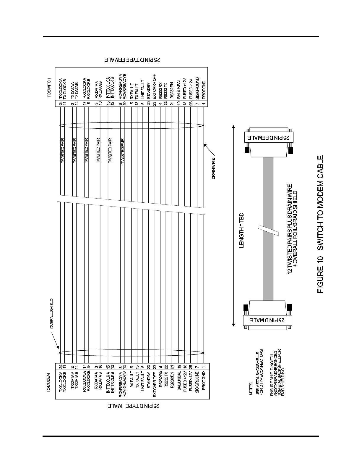
CRS-200 COMTECH COMMUNICATIONS CORPORATION
CRS-200 REDUNDANCY SWITCH - OPERATIONS MANUAL PAGE 58
 Loading...