

Page 1

CPLINK
XCVR Palm Link 2
Software Version 2.1
Installation and Operation Manual
Part Number MN/CPLINK.IOM Revision 1
Page 2

Page 3

XCVR Palm Link 2.1
p
Comtech EF Data Palm Link
(CPLINK)
User's Guide
CPLINK software supports
Comtech EF Data monitor
and control of all high
ower CSAT and XSAT
transceiver systems.
Software Version 2.1
Copyright Comtech EF Data Corporation 2002
MN/CPLINK.IOM Revision 1
Shown: Palm m500
1
Page 4

2
Page 5

Table of Contents
What is CPLINK? ............................................................................................................... 5
1. Installing the CPLINK Program ............................................................................... 5
2. Connecting the Palm Handheld Device................................................................. 6
3. The Main Menu (Ref: Fig. 3).................................................................................. 6
4. General Information.................................................................................................. 7
5. Configuration ............................................................................................................ 8
6. System Type.............................................................................................................. 9
7. Signal Path Configuration....................................................................................... 10
8. LNA Configuration................................................................................................. 11
10. Redundancy Controller ......................................................................................... 13
11. Maintenance Status ............................................................................................... 14
14. Set Time / Date & Circuit ID Msg. (CID) ............................................................ 17
Appendix A....................................................................................................................... 18
1. Communications Setup:........................................................................................... 18
2. About CPLINK21: .................................................................................................. 19
3. About Expansion cards ........................................................................................... 20
4. Copying a program from the SD expansion card to RAM ..................................... 20
5. Batteries .................................................................................................................. 21
6. Cable Connections .................................................................................................. 21
Comtech EF Data Corporation
2114 West 7
Tempe, AZ 85281 USA
Tel: 480.333.2200
Fax: 480.333.2161
http://www.comtechefdata.com
th
Street
3
Page 6

4
Page 7

The Comtech EF Data XCVR CPLINK software is compatible with most of the Palm
Operating System handheld devices. Instructions are included for use with the Palm
model m500, however, any other compatible Palm device may be substituted as
required. Refer to your particular Palm owner's manual to become familiar with the
operation of the Palm including the SD memory card if applicable.
What is CPLINK?
CPLINK is a software application program that is Palm Operating System compatible.
With CPLINK installed and operating on one of the Palm handheld devices, the user
can monitor and control all functionality of Comtech EF Data CSAT and XSAT high
power transceiver systems.
CPLINK stands for C
1. Installing the CPLINK Program
! Install the "Hot Sync" software included with the Palm m500 package on a
Windows based PC.
! Using the cable or cradle supplied with the Palm m500, connect the m500 to a
USB (universal serial port) or a standard serial port of the PC.
! Using Windows Explorer, locate the CPLINKxx.prc (where xx is the version
number) file provided by Comtech EF Data. Double click this file. Note:
Double clicking on the .prc file will activate the "Hot Sync" software. Follow the
on screen instructions to prepare the file for loading into the Palm device on the
next "Hot Sync".
! Push the "Hot Sync" button on the cable / cradle that connects to the Palm
m500, or select the "Hot Sync" icon on the screen of the m500. This action
should initiate the uploading of the CPLINK file to the Palm. When this is
done, the Palm is ready to connect to the Redundancy Controller Box (RED
Box) or a single XCVR.
omtech EF Data Palm LINK.
5
Page 8

2. Connecting the Palm Handheld Device
! Using the two Comtech EF Data cables provided (CEFD part numbers
PP/PALM-P10804U, Palm to 9 pin D (female) and CA/WR9902, 9 pin D (male)
to RED Box), connect the Palm handheld device to the 19 pin M&C connector
on the RED Box. Alternately, if a non-redundant (standalone) system is used,
connect the provided cables to the XCVR 19 pin M&C connector directly. See
note below.
! Turn power on the Palm m500 and press the CPLINK icon to start the CPLINK
program. The Main Menu will be displayed.
Note: If using a Palm m100 or m105 only one cable (CEFD part number CA/WR9185) is
required to connect the Palm to the RED Box or single XCVR. The Palm m125, m500 and
other models use two interconnecting cables to provide communication from the Palm to the RED
Box. See Appendix item 6 for additional details.
3. The Main Menu (Ref: Fig. 3)
! General Information
Configuration
# System Type
# Signal Path
# LNA
# Miscellaneous
# Redundancy Controller
! Maintenance Status
! Current Fault Status
! Stored Events/Alarms
! Set Time/Date & CID
$ Home (icon)
$ Menu Bar (icon)
Fig 3
The above Main Menu items are described in detail in the following sections:
6
Page 9
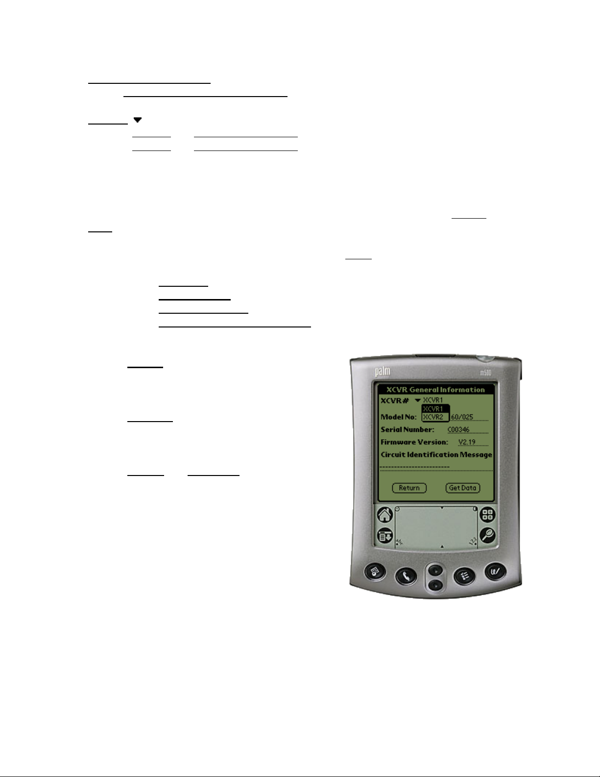
4. General Information
Main Menu > General Information (Ref: Fig. 4)
XCVR#
Sets the "currently selected XCVR".
The "currently selected XCVR" is the XCVR that will be polled for status information in
the XCVR General Information menu. The XCVR# is not displayed if the software is set
to a standalone (non-redundant) system. (See setting the System Type in the System
Type section for more information).
The General Information menu displays the following status
selected XCVR":
In this particular example, the data from XCVR #1
will be displayed.
XCVR1
XCVR2 (transceiver #2 select)
% Model No
% Serial number – displays the currently selected XCVR serial number
% Firmware version – the currently selected XCVR firmware version
% Circuit Identification Message (CID) – the currently selected XCVR
# (Return) button – returns the user back to
# (Get Data) button – will request data from
# (Update) or (Send Data) buttons – (not
(transceiver #1 select)
– displays the currently selected XCVR model number
programmable text message
the Main Menu and will NOT
program any programmable
parameters.
the currently selected XCVR
to refresh the XCVR General
Information screen.
shown) will program the
Palm device with any
parameters that have changed
since the menu was
displayed.
parameters of the "currently
Fig. 4
7
Page 10
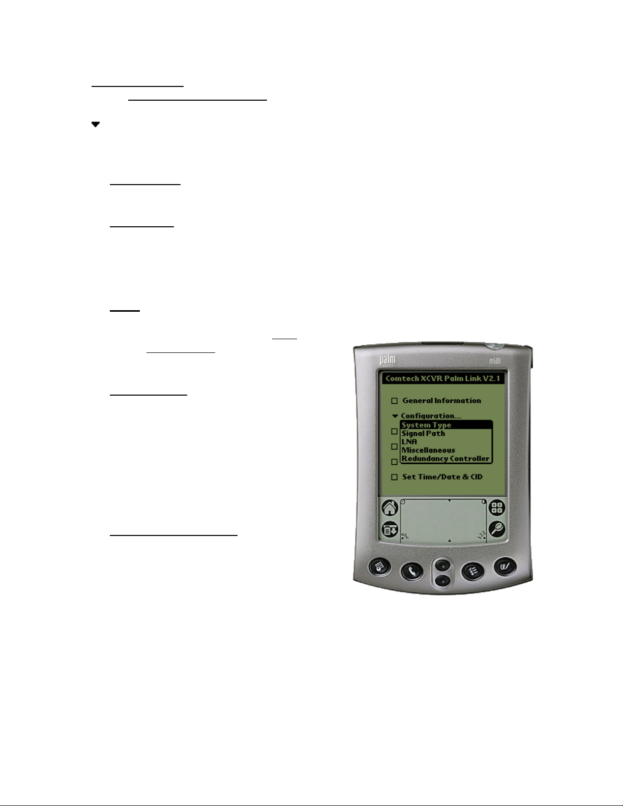
5. Configuration
Main Menu > Configuration (Ref: Fig. 5)
Configuration…
There are five (5) configuration modes to choose from:
# System Type:
# Signal Path: Select Signal Path to view and change the Upconverter Frequency.
# LNA: Select LNA to view and change Current Source ON/OFF, XCVR Fault Logic
ON/OFF, the allowable Current Window, and the percent Current change.
Reference the menu item LNA
Configuration for additional
information.
# Miscellaneous: Select Miscellaneous to
# Redundancy Controller: Online Unit
Selects between a standalone system (1 transceiver) and a 1:1
redundant system.
Upconverter Amplifier attenuation (00.00-20.00 dB), Amp ON/OFF,
Mute ON/OFF, Downconverter Frequency, Downconverter
Frequency, Downconverter Attenuation (00.00-20.00 dB), Mute
ON/OFF XCVR parameters.
view or change Cold Start,
Auto Fault Recovery
(AFR), Local Reference
Oscillator Adjustment,
External Reference Fault
Logic, and Up and Down
converter slope
adjustments.
(XCVR) selector,
Operating Mode
AUTO/MAN, Waveguide
Switch Status OK/FT,
Controller Voltages
monitoring +5VDC and +12VDC.
Fig. 5
8
Page 11
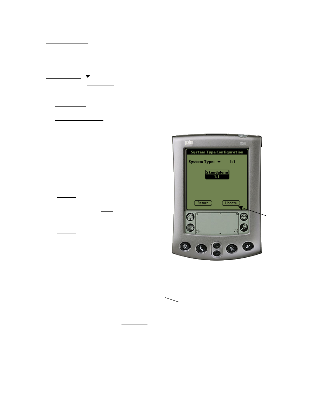
6. System Type
Main Menu > Configuration > System Type (Ref. Fig. 6)
There are two (2) modes of operation when using the CPLINK software.
System Type:
Standalone
1:1
# Standalone: This mode is usually selected when used with a single XCVR.
# One for One (1:1): The 1:1 mode is selected when two (2) XCVRs are used in a
redundant system configuration with a redundant controller box
(RED box). This mode
can allow the user to
control the online /
offline XCVR through
the RED box. See the
Redundancy Controller
menu to control or view
operating parameters.
o (Return) button – Returns the user back to
the Main Menu and will
NOT program any
selection changes.
o (Update) button – Programs the Palm
device with any change
since the System Type
Configuration was
displayed.
Note: The Main Menu > Configuration > Redundancy Controller can only be selected if
the 1:1 parameter
(1:1) mode.
It should be noted that when the 1:1
slightly different than when in standalone
will have an option to select XCVR #1 (A) or XCVR #2 (B). When selecting XCVR #1,
the parameters and controls are displayed for XCVR #1. Alternately, when XCVR #2 is
selected, the corresponding parameters and controls are displayed for the (B) XCVR.
Note: XCVR #1 and (A) are used interchangeably. The same holds true for XCVR #2
and (B).
is highlighted and the update button is pressed to program redundancy
system is selected, some of the menus may look
mode. The major difference is that the user
Fig. 6
9
Page 12

7. Signal Path Configuration
Main Menu > Configuration > Signal Path (Ref. Fig. 7)
XCVR1 (transceiver #1 select)
XCVR2
ONLINE/OFFLINE status field: (Status only). Displays the line status of the currently
selected XCVR.
TX Stat: (Status Only). This is a summary of the Amp=ON, Mute=OFF and no faults
present.
RX Stat: (Status Only). This is a summary of the Mute=OFF and no faults present.
Amp: (On/Off) The user can change the state of the amplifiers in the currently
selected XCVR to ON or OFF.
Mute: (On/Off) Allows the user to mute the output of the currently selected XCVR
(Return) button – returns the user back to the Main Menu and will NOT program any
programmable parameters.
(Update) button – will program the Palm device with any parameters that have
changed since the menu was displayed or the last time the (Update) button was pressed.
(transceiver #2 select)
when set to ON.
*Frequency: Both the transmitter frequency
and the receiver frequency are user configurable.
The transmit frequency can be selected to any
frequency divisible by either 1.0 MHz or 2.5
MHz in the valid TX frequency range. The
receive frequency can be selected to any
frequency divisible by either 1.0 MHz or 2.5
MHz in the valid RX frequency range.
*Attenuation: Both the transmit and receive
attenuation are user configurable. The TX and
RX attenuation can be selected between 00.00
dB and 20.00 dB in 0.25 dB increments.
*Note:
and Attenuation settings can only be changed if
the currently selected XCVR is ONLINE.
Fig. 7
The Up and Down converter Frequency
10
Page 13

8. LNA Configuration
Main Menu > Configuration > LNA (Ref. Fig. 8)
XCVR#
ONLINE/OFFLINE status field:
(Status only). Displays the line status of the currently selected XCVR.
Current Source: (Enabled/Disabled) The XCVR has the circuitry to source up to
400 mA of current at 12 VDC to power a LNA. The user can turn this current source
ON/OFF. Care should be taken when directly connecting the XCVR to lab test
equipment: a DC block should be used between the "RF IN" port and the RF test source
to protect the test equipment in case the source is accidentally turned on.
Fault Logic: (On/Off) The XCVR allows the user to select whether or not the
summary fault relay is activated if the LNA current moves out of the prescribed window.
This allows the user to control whether or not the redundancy controller will switch on a
LNA current alarm in the redundant configuration.
Current Window: (Enabled/Disabled)
The XCVR provides the capability to monitor
the LNA current when configured to supply
current to the LNA. In addition, an adjustable
window detect for the LNA current is
provided. After attaching the LNA and
turning on the current source, the user can
"Calibrate" the current and set a window from
+/- 20% to +/-50% to trigger an alarm. The
user can disable the "window detect" feature
by setting the window value to +/- 99%.
Allowable Change:
the documentation in the Current Window
above.
(Return
programmable parameters.
(Update) button – will program the Palm device with any parameters that have
changed since the menu was displayed or the last time the (Update) button was pressed.
XCVR1
XCVR2 (transceiver #2 select)
) button – returns the user back to the Main Menu and will NOT program any
(transceiver #1 select)
+/- 20% to +/- 50%. See
Fig. 8
11
Page 14

9. Miscellaneous Configuration
Main Menu > Configuration > Miscellaneous (Ref. Fig. 9)
XCVR#
*Cold Start: (On/Off) The XCVR provides an optional "Cold Start" feature that will
insure that the internal 10 MHz reference signal is at a stable temperature prior to
allowing the RF and IF outputs to be turned on. A fixed cold start interval of 15 minutes
is used. At the end of the 15 minute interval, the RF and IF outputs will automatically be
turned ON providing all fault conditions and appropriate settings are met. If a XCVR
was powered ON with "Cold Start ON", the operator can override this function by
selecting "Cold Start OFF".
*Auto Fault Recovery (AFR): (On/Off) This parameter defines how the XCVR
responds to momentary fault conditions. If AFR is OFF and a fault condition occurs that
causes the RF or IF output to be muted, then that fault condition clears, the XCVR will
remain muted. If AFR is ON, and the same situation occurs, the XCVR will
automatically be unmuted and return to normal operating mode. To protect against
repetitive, momentary faults, if the XCVR experiences 5 occurrences of the same fault,
the AFR parameter will automatically be set to OFF.
*Note: The Cold Start and AFR settings can only be changed if the currently selected
XCVR is ONLINE.
XCVR1
XCVR2 (transceiver #2 select)
(transceiver #1 select)
Local Ref Osc Adjust: A fine adjustment of
the internal 10 MHz frequency is provided as a
user controllable parameter. This parameter can
be varied within the range of 000 to 255.
Ext Ref Present: (Status only).
reference is connected to the XCVR, this
parameter will display the status of the signal.
Ext Ref Fault Logic: (On/Off) The XCVR
allows the user to select whether or not the
summary fault relay is activated if the internal
10 MHz reference loses lock with the external
reference attached to the "EXTERNAL REF IN"
port J4.
Up/Dn Conv Slope Adjust:
channel slopes can be adjusted from 0.0 (factory
setting) to 1.0 in 0.1 steps. 1.0 corresponds to
approx. 2 dB of positive slope.
Fig. 9
ONLINE/OFFLINE status field:
(Status only). Displays the line status
of the currently selected XCVR.
If an external
The TX and RX
12
Page 15

10. Redundancy Controller
Main Menu > Configuration > Redundancy Controller (Ref. Fig. 10)
Online Unit:
XCVR1 (transceiver #1 select)
XCVR2 (transceiver #2 select)
Allows the user to observe or select which XCVR in a redundancy configuration is
currently online or offline. To change the online unit, the trigger should be pressed to
display the two options (XCVR1 or XCVR2). Highlight the desired XCVR to switch
online, and press the (Update) button.
The Online Unit should not be confused with the "Currently Selected XCVR"
Note:
selector that is present in several other menus. This is the only menu where the user has
the capability to "force" a XCVR to be the ONLINE
Operating Mode: (Auto/Manual) Allows the
user to control the operating mode of the RSU5060 (RED Box). The operating mode selections
are Auto or Manual modes. When in Auto mode,
the RED box monitors the state of XCVR1 and
XCVR2 (A and B). If the ONLINE unit fails, the
RED box will automatically command both the
TX and RX transfer switches to change position.
Note: If the OFFLINE unit is also faulted, no
switchover will occur. Manual mode will not
monitor fault status for automatic switchover. To
change operating modes, the trigger ( ) should be
pressed to display the two options. Highlight the
desired mode and press the (Update) button.
TXWG Switch Status: (Status only). Reports
the status OK/FT of the TX waveguide switch.
RXWG Switch Status:
the status OK/FT of the TX waveguide switch.
Controller Voltages: (Status only). Displays the RED
box internal power supply voltages.
(Return
programmable parameters.
(Update) button – will program the Palm device with any parameters that have
changed since the menu was displayed.
) button – returns the user back to the Main Menu and will NOT program any
(Status only). Reports
or OFFLINE XCVR.
Fig. 10
13
Page 16

11. Maintenance Status
Main Menu > Maintenance Status (Ref. Fig. 11)
XCVR#
XCVR Internal Voltages: The XCVR unit monitors the 6 internal DC voltages:
24,20,12,10,+5 and –5. The voltages are displayed for the currently selected XCVR.
These voltages are updated when the Maintenance screen is entered, or if the currently
selected XCVR is changed, or if the (Get Data) button is pressed.
Tuning (Volts): The XCVR monitors the 4 tuning voltages which are variable
(Return) button – returns the user back to the Main Menu and will NOT query the
currently selected XCVR for data.
(Get Data
XCVR1
XCVR2 (transceiver #2 select)
) button – will query the selected XCVR and refresh the current data screen.
(transceiver #1 select)
depending on frequency. These voltages are
updated when the Maintenance screen is
entered, or if the currently selected XCVR is
changed, or if the (Get Data) button is pressed.
Currents (mA): The cooling fan and the LNA
currents are displayed in milliamps and can be
refreshed with the (Get Data) button or as in the
above 2 sections.
Temperatures: The Up Slice and Down Slice
temperatures are displayed in degerees C. These
temperatures can be refreshed with the (Get
Data) button or as in the first 2 sections.
RF Power (dBm): The actual RF output power
of the Upconverter is displayed in dBm. This
power can be updated by pressing the (Get
Data) button or as in the first 2 sections.
Fig. 11
14
Page 17

12. Current Fault Status
Main Menu > Current Fault Status (Ref. Fig. 12)
XCVR#
XCVR Internal Voltages: The XCVR unit monitors the 6 internal DC voltages:
24,20,12,10, +5 and –5 for the currently selected XCVR. The monitor circuitry will
display a fault (FT) if any of these voltages are +/- 10% out of range. These voltages are
updated when the current fault status screen is entered, or if the currently selected XCVR
is changed, or if the (Get Data) button is pressed.
Lock Detects:
fault is displayed for any and each PLL that is not locked. These lock statuses are
updated when the (Get Data) button is pressed, or as in the above selection.
Currents & Temperatures:
Fan are monitored for excessive and low
currents. A fault is displayed if these currents
are out of their prescribed window. If the
temperature rises out of specification for the
XCVR, a fault will appear in the Heat Sink
field. As the heat sink temperature continues
to rise, the XCVR will automatically disable
the FET amplifiers and display a shutdown
fault.
Processor: The Chksum (checksum), IIC
Bus, and the battery are monitored for proper
operation and will display a faulted condition
(FT) when the processor system is not
functioning properly.
(Return
currently selected XCVR for data.
(Get Data
XCVR1
XCVR2 (transceiver #2 select)
) button – returns the user back to the Main Menu and will NOT query the
) button – will query the selected XCVR and refresh the current data screen.
(transceiver #1 select)
The XCVR monitors the 4 phase lock loops (PLLs) for each XCVR. A
The LNA and
Fig. 12
15
Page 18

13. Stored Events & Alarms
Main Menu > Stored Events & Alarms (Ref. Fig. 13)
Total New Events:
stored events log.
XCVR indicator field:
displays the currently selected XCVR. This is a status only and the currently selected
XCVR cannot be changed in this menu.
Retrieve Next 5 Events: This (OK) button will update the Event display with up to the
next 5 events.
Event Window:
Clear Event Log:
shown in Fig. 12.1.
Reset Event Pointer: This (OK) button will reset the event pointer to the top of the
event list to show the start of the event log.
The number of events that have occurred since last viewing the
This field to the immediate right of the Stored Events number
Where the stored events are displayed and updated.
Will erase any events in the event log and provide a clear display as
Fig. 13
(Return) button – returns the user back to the Main Menu and will NOT query the
currently selected XCVR for data.
(Get Data) button – This will refresh the Event Window with any new event data.
16
Page 19

14. Set Time / Date & Circuit ID Msg. (CID)
Main Menu > Stored Events/Alarms (Ref. Fig. 14)
XCVR#
Date: Displays the date of the currently selected
XCVR.
Time: Displays the time of the currently selected
XCVR.
(NOW) button:
Palm device.
Circuit Identification Message:
message. The CID is displayed for the currently
selected XCVR.
(Get Data) button – Retrieves the Date, Time,
and CID message from the currently selected
XCVR.
(Send Data) button – Sends the indicated Date,
Time, and CID message to the currently selected
XCVR.
(Return) button – Returns to the Main Menu and will NOT query or program the
currently selected XCVR.
XCVR1
XCVR2 (transceiver #2 select)
(transceiver #1 select)
Displays the date and time of the
This is the CID
Fig. 14
17
Page 20

Appendix A
Menu Bar Options
1. Communications Setup:
Menu Bar Icon > Options >Communications
Note: The Menu Bar is accessed on the Palm
m500 and other models by tapping the pointer
on the fixed menu bar icon / button in the
bottom left corner (just to the left of the abc-dot
area) of the Palm device. Some Palm
devices allow the upper black bar to be tapped
to drop down the options menu.
Baud Rate: The Baud Rate can be manually
set to 1200, 2400, 4800, 9600, or 19200.
XCVR Address: The XCVR address can also
be set manually from 1-999.
If the Baud Rate and / or XCVR Address is not
known, the CPLINK software can locate the
connected XCVRs.
(Find XCVR
be set to address #1 and the redundant XCVR (if
applicable) will be set to address #2.
(OK
) button – The displayed baud rate and
address information are programmed into the
Palm.
) button – The found XCVR will
18
Page 21

2. About CPLINK21:
Menu Bar Icon > Options > About CPLink21
About CPLink21 will display the software version number and company information.
Visit the Comtech EF Data web site at http://www.comtechefdata.com for the latest
product updates and customer support information.
(OK) button – Returns the user to the Main Menu.
19
Page 22
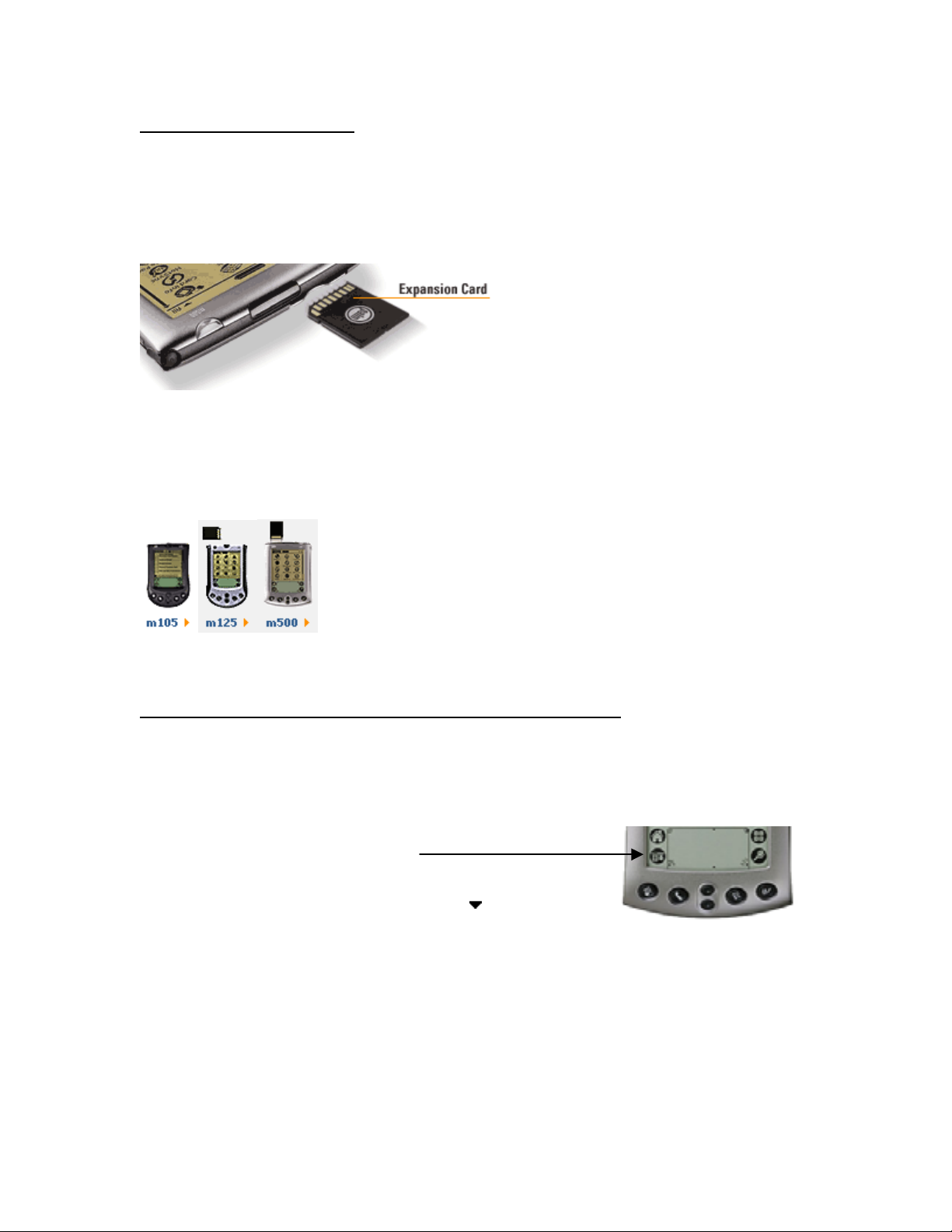
3. About Expansion cards
Several current models of Palm handhelds support SD (secure digital) Memory
Expansion Cards. These expansion cards offer the advantage of being able to retain a
software program (such as CPLINK) when batteries get low or fail completely.
If the user has a Palm with the SD expansion card and loses battery power, it is then a
simple matter to replace the AAA batteries (m125), or recharge the unit (m500). The
CPLINK program can then be copied back into RAM (Random Access Memory) from
the SD card.
The m125 and the m500 support Expansion Cards
while the m100 and m105 handhelds do not.
4. Copying a program from the SD expansion card to RAM
It is a simple procedure to copy a program such as CPLINK to or from RAM in the Palm
devices that support SD expansion cards.
1. With the Palm turned on tap the menu bar icon at the
bottom of the digitizer screen.
2. Select "Copy" from the pull down list.
3. At the top of the screen select Copy To:
4. Highlight the program to copy (in this case it is CPLink).
5. Select the (Copy) button at the bottom of the screen.
6. If the program exists in RAM on the handheld, you will be asked if you want to
replace it. If it doesn't already exist - go to step 8.
7. If yes is selected, the old version will be overwritten with the version from the SD
card.
8. Select (Done) when the copy has completed.
Handheld.
20
Page 23

5. Batteries
Since the m100 (no longer in production) and m105 /m125 use AAA batteries, it is
prudent to replace the batteries with fresh ones if the Palm will be in use for an
extended period of time. The m100 and the m105 models do not support expansion cards.
If the batteries fail on either of these two Palms, the CPLINK program will be lost and
will have to be reloaded from a local PC via HOTSYNC operation.
There are capacitors built into the Palm m100 / m105 devices to provide about 1 minute
of sustained power while changing the batteries. This should provide enough time to
change the batteries without having to reload the CPLINK program.
6. Cable Connections
A single cable is used to connect the Palm models
M100 and m105 to the Redundancy Controller
(RED Box). CEFD P/N: CA/WR9185
RED
BOX
or
XCVR
If using Palm models m125 or m500,
two cables are provided. Connect the 9
pin D male-female connectors together,
then connect the Palm handheld to the
RED Box or XCVR.
RED
BOX
or
XCVR
CEFD part number:
PP/PALM-P10804U
CEFD part number:
CA/WR9902
21
Page 24

Notes
www.comtechefdata.com
22
Page 25

Page 26

2114 WEST 7TH STREET TEMPE ARIZONA 85281 USA
480 • 333 • 2200 PHONE
480 • 333
• 2161 FAX
 Loading...