

Page 1
CMR-5910 / CMR-5920
Digicast Media Router Serial IP (SIP)
CMR-5910 – Serial IP Gateway (MG-SIP)
CMR-5920 – Serial IP Router (MR-SIP)
Comtech EF Data is an ISO 9001
Registered Company
Comtech EF Data, 2114 West 7th Street, Tempe, Arizona 85281 USA, (480) 333-2200, FAX: (480) 333-2161
Installation and Operation Manual
Part Number MN/MDRTRIPDC.IOM
Revision A
May 10, 2007
Copyright © Comtech EF Data, 2007. All rights reserved. Printed in the USA.
Page 2

Page 3

Table of Contents
PREFACE.................................................................................................................................. VII
Customer Support.....................................................................................................................................vii
About this Manual ................................................................................................................................... viii
Related Documents................................................................................................................................viii
Reporting Comments or Suggestions Concerning this Manual.............................................................viii
Conventions and References...................................................................................................................viii
Cautions and Warnings..........................................................................................................................viii
Metric Conversion................................................................................................................................... ix
Recommended Standard Designations....................................................................................................ix
Trademarks..............................................................................................................................................ix
Electromagnetic Compatibility (EMC) Compliance...............................................................................ix
Emissions Compliance ............................................................................................................................ix
EN61000 Compliance...............................................................................................................................x
Safety Compliance ......................................................................................................................................x
EN60950 Compliance...............................................................................................................................x
Low Voltage Directive (LVD) ................................................................................................................. x
Warranty Policy.........................................................................................................................................xi
Limitations of Warranty ..........................................................................................................................xi
Exclusive Remedies................................................................................................................................xii
CHAPTER 1. INTRODUCTION...........................................................................................1–1
1.1 Introduction................................................................................................................................ 1–1
1.2 Standard Features......................................................................................................................1–2
1.3 Performance...............................................................................................................................1–2
1.4 Configuration.............................................................................................................................1–2
1.5 Specifications..............................................................................................................................1–3
1.6 Terminology ...............................................................................................................................1–5
i
Page 4

Digicast Media Router Serial IP (SIP): CMR-5910 (MG-SIP) & CMR-5920 (MR-SIP) Revision A
MN/MDRTRIPDC.IOM
CHAPTER 2. INSTALLATION & INITIAL CONFIGURATION.................................................2-1
2.1 Major Assembly..........................................................................................................................2-1
2.2 Unpacking....................................................................................................................................2-1
2.3 Installation...................................................................................................................................2-2
2.4 Initial Configuration...................................................................................................................2-3
CHAPTER 3. INTERFACE PINOUTS......................................................................................3-1
3.1 Pinout Overview..........................................................................................................................3-1
3.2 DC Power.....................................................................................................................................3-1
3.3 RJ-45 Ethernet............................................................................................................................3-1
3.4 RJ-12 Redundancy (future) .......................................................................................................3-2
3.5 RJ-12 Terminal...........................................................................................................................3-2
3.6 RS-422..........................................................................................................................................3-2
CHAPTER 4. DEVICE MANAGEMENT VIA USER INTERFACES: CMR-5910 (MG-SIP) .....4-1
4.1 Introduction.................................................................................................................................4-1
4.2 Web Interface..............................................................................................................................4-1
4.2.1 Administrative Configuration...................................................................................................4-2
4.2.2 Syslog Configuration................................................................................................................4-4
4.2.3 Network Configuration.............................................................................................................4-5
4.2.4 HDLC Egress Configuration....................................................................................................4-6
4.2.5 (HDLC TX) Route Configuration ............................................................................................4-7
4.2.6 Statistics....................................................................................................................................4-9
4.3 Terminal Interface....................................................................................................................4-11
4.3.1 Main Menu .............................................................................................................................4-12
4.3.2 Administration Menu..............................................................................................................4-12
4.3.3 HDLC Configuration Menu....................................................................................................4-13
4.3.3.1 (Uplink) HDLC Route Configuration Menu..................................................................4-13
4.3.3.1.1 HDLC Advanced Route Configuration Menu..........................................................4-14
4.3.4 Egress Configuration Menu ....................................................................................................4-14
4.3.5 Stats (Statistics) Menu............................................................................................................4-15
4.3.5.1 HDLC Uplink Stats Menu .............................................................................................4-15
4.3.5.2 Ethernet Stats Menu.......................................................................................................4-16
4.3.6 Network Configuration Menu ................................................................................................4-16
4.4 Telnet Interface.........................................................................................................................4-17
ii
Page 5

Digicast Media Router Serial IP (SIP): CMR-5910 (MG-SIP) & CMR-5920 (MR-SIP) Revision A
MN/MDRTRIPDC.IOM
4.5 Trivial File Transfer Protocol (TFTP)....................................................................................4-18
4.6 Simple Network Management Protocol (SNMP)............................................................4-19
CHAPTER 5. DEVICE MANAGEMENT VIA USER INTERFACES: CMR-5920 (MR-SIP)............5-1
5.1 Introduction.................................................................................................................................5-1
5.2 Web Interface..............................................................................................................................5-1
5.2.1 Administrative Configuration...................................................................................................5-2
5.2.2 Syslog Configuration................................................................................................................5-4
5.2.3 Network Configuration.............................................................................................................5-5
5.2.4 IGMP Configuration.................................................................................................................5-6
5.2.5 Unicast Routing Configuration.................................................................................................5-7
5.2.6 HDLC RX Configuration .........................................................................................................5-8
5.2.7 Statistics....................................................................................................................................5-9
5.3 Terminal Interface....................................................................................................................5-10
5.3.1 Main Menu .............................................................................................................................5-11
5.3.2 Administration Menu..............................................................................................................5-11
5.3.3 HDLC Configuration Menu....................................................................................................5-12
5.3.3.1 (Downlink) HDLC Address Configuration Menu.........................................................5-12
5.3.4 IGMP Configuration Menu ....................................................................................................5-13
5.3.5 Stats (Statistics) Menu............................................................................................................5-13
5.3.5.1 HDLC Downlink Stats Menu.........................................................................................5-14
5.3.5.1.1 Detailed Downlink Stats Menu.................................................................................5-14
5.3.5.2 Ethernet Stats Menu.......................................................................................................5-15
5.3.6 Network Configuration Menu ................................................................................................5-15
5.3.7 Unicast Routing Configuration Menu ....................................................................................5-16
5.4 Telnet Interface.........................................................................................................................5-16
5.5 Trivial File Transfer Protocol (TFTP)....................................................................................5-17
5.6 Simple Network Management Protocol (SNMP) (Future)...........................................5-18
APPENDIX A. SOFTWARE UPGRADE.............................................................................. A–1
A.1 Introduction............................................................................................................................... A–1
A.2 Web Interface............................................................................................................................ A–2
A.3 Telnet or Terminal Interface ................................................................................................... A–3
APPENDIX B. IP ROUTING SUPPORT...............................................................................B-1
B.1 Introduction................................................................................................................................B-1
B.2 Route Configuration..................................................................................................................B-1
iii
Page 6

Digicast Media Router Serial IP (SIP): CMR-5910 (MG-SIP) & CMR-5920 (MR-SIP) Revision A
MN/MDRTRIPDC.IOM
B.2.1 Unicast Routing....................................................................................................................... B-1
B.2.2 Multicast Routing.................................................................................................................... B-2
B.3 64 Routes.....................................................................................................................................B-2
B.4 Multicast Zones..........................................................................................................................B-2
B.5 Quality of Service (QoS)............................................................................................................ B-3
APPENDIX C. SYSTEM LOG CONFIGURATION............................................................... C–1
C.1 Introduction............................................................................................................................... C–1
C.2 Enabling a System Logger........................................................................................................C–1
APPENDIX D. TROUBLESHOOTING................................................................................. D–1
Tables
Table 1-1. Digicast MG-SIP / MR-SIP Specifications .............................................................................1–4
Table 2-1. Digicast Serial IP – Standalone Configuration.........................................................................2-1
Figures
Figure 1-1. Digicast Serial IP MG-SIP / MR-SIP – Front Panels.............................................................1–1
Figure 1-2. Digicast Serial IP MG-SIP / MR-SIP Operational Configuration..........................................1–3
Figure 1-3. Digicast Serial IP MG-SIP / MR-SIP – Rear Panel (typical).................................................1–3
Figure 3-1. Digicast Serial IP MG-SIP / MR-SIP – Rear Panel (typical)..................................................3-1
Figure 4-1. Connecting to the MG-SIP......................................................................................................4-1
Figure 4-2. MG-SIP Home (“Splash”) page..............................................................................................4-2
Figure 4-3. Administrative Configuration page.........................................................................................4-2
Figure 4-4. Syslog Configuration page......................................................................................................4-4
Figure 4-5. Network Configuration page...................................................................................................4-5
Figure 4-6. HDLC Egress Configuration page ..........................................................................................4-6
Figure 4-7. (HDLC TX) Route Configuration page...................................................................................4-7
Figure 4-8. Uplink Route Statistics page...................................................................................................4-9
Figure 4-9. Menu Hierarchy (via Terminal Interface) .............................................................................4-11
Figure 4-10. Main Menu..........................................................................................................................4-12
iv
Page 7

Digicast Media Router Serial IP (SIP): CMR-5910 (MG-SIP) & CMR-5920 (MR-SIP) Revision A
MN/MDRTRIPDC.IOM
Figure 4-11. Administration Menu ..........................................................................................................4-12
Figure 4-12. HDLC Configuration Menu................................................................................................4-13
Figure 4-13. (Uplink) HDLC Route Configuration Menu.......................................................................4-13
Figure 4-14. HDLC Advanced Route Configuration Menu.....................................................................4-14
Figure 4-15. Egress Configuration Menu ................................................................................................4-14
Figure 4-16. Stats Menu...........................................................................................................................4-15
Figure 4-17. HDLC Uplink Stats Menu ...................................................................................................4-15
Figure 4-18. Ethernet Stats Menu............................................................................................................4-16
Figure 4-19. Network Configuration Menu.............................................................................................4-16
Figure 4-20. Starting Telnet Session ........................................................................................................4-17
Figure 4-21. Main Menu via Telnet.........................................................................................................4-17
Figure 5-1. Connecting to the MR-SIP......................................................................................................5-1
Figure 5-2. MR-SIP Home (“Splash”) page ..............................................................................................5-2
Figure 5-3. Administrative Configuration page.........................................................................................5-2
Figure 5-4. Syslog Configuration page......................................................................................................5-4
Figure 5-5. Network Configuration page...................................................................................................5-5
Figure 5-6. IGMP Configuration page.......................................................................................................5-6
Figure 5-7. Unicast Routing Configuration page .......................................................................................5-7
Figure 5-8. HDLC RX Configuration page ...............................................................................................5-8
Figure 5-9. HDLC Downlink Route Statistics page...................................................................................5-9
Figure 5-10. Menu Hierarchy (via Terminal Interface) ...........................................................................5-10
Figure 5-11. Main Menu..........................................................................................................................5-11
Figure 5-12. Administration Menu ..........................................................................................................5-11
Figure 5-13. HDLC Configuration Menu................................................................................................5-12
Figure 5-14. (Downlink) HDLC Address Configuration Menu...............................................................5-12
Figure 5-15. IGMP Configuration Menu.................................................................................................5-13
Figure 5-16. Stats Menu...........................................................................................................................5-13
Figure 5-17. HDLC Downlink Stats Menu..............................................................................................5-14
Figure 5-18. Detailed Downlink Stats Menu...........................................................................................5-14
Figure 5-19. Ethernet Stats Menu............................................................................................................5-15
Figure 5-20. Network Configuration Menu.............................................................................................5-15
Figure 5-21. Unicast Routing Configuration Menu.................................................................................5-16
Figure 5-22. Starting Telnet Session ........................................................................................................5-16
Figure 5-23. Main Menu via Telnet.........................................................................................................5-17
Figure A-1. TFTP Download (via Web Interface – MG-SIP shown)......................................................A–2
Figure A-2. Sample TFTP (via Terminal Interface – MG-SIP shown) ...................................................A–3
Figure A-3. TFTP Download (via Telnet Interface)................................................................................A–4
v
Page 8

Digicast Media Router Serial IP (SIP): CMR-5910 (MG-SIP) & CMR-5920 (MR-SIP) Revision A
MN/MDRTRIPDC.IOM
This page is deliberately left blank.
vi
Page 9

Customer Support
Contact the Comtech EF Data Customer Support Department for:
• Product support or training
• Reporting comments or suggestions concerning manuals
• Information on upgrading or returning a product
A Customer Support representative may be reached at:
Comtech EF Data
Attention: Customer Support Department
2114 West 7th Street
Tempe, Arizona 85281 USA
480.333.2200 (Main Comtech EF Data number)
480.333.4357 (Customer Support Desk)
To return a Comtech EF Data product (in-warranty and out-of-warranty) for repair or replaceme nt:
For Online Customer Support:
An RMA number request can be requested electronically by contacting the Customer Support
Department through the online support page at
For information regarding this product’s warranty policy, refer to the Warranty Policy, p. xi.
480.333.2161 FAX
• Contact the Comtech EF Data Customer Support Department. Be prepared to supply the
Customer Support representative with the model number, serial number, and a description
of the problem.
• Request a Return Material Authorization (RMA) number from the Comtech EF Data
Customer Support representative.
• Pack the product in its original shipping carton/packaging to ensure that the product is not
damaged during shipping.
• Ship the product back to Comtech EF Data. (Shipping charges should be prepaid.)
• Click on “Return Material Authorization” for detailed instructions on our return
procedures.
• Click on the “RMA Request Form” hyperlink, then fill out the form completely before
sending.
• Send e-mail to the Customer Support Department at service@comtechefdata.com.
Preface
www.comtechefdata.com/support.asp:
vii
Page 10

Digicast Media Router Serial IP (SIP): CMR-5910 (MG-SIP) & CMR-5920 (MR-SIP) Revision A
Preface MN/MDRTRIPDC.IOM
About this Manual
This manual provides installation and operation information, functional capabilities,
and performance specifications for the Comtech EF Data (CEFD) Digicast Serial IP
Routers – CMR-5910 Digicast Media Gateway (MG-SIP) and CMR-5920 Digicast
Media Router (MR-SIP) – referred to throughout this manual as “the MG-SIP” or “the
MR-SIP”. The manual additionally provides information on how to connect these
products to other data transport equipment.
This is a technical document intended for earth station engineers, technicians, and
operators responsible for the operation and maintenance of the MG-SIP and MR-SIP.
Related Documents
• ISO/IEC – HDLC Protocol Specifications
• IEEE802.x - Ethernet specifications
• RFCs – Internet-related official standards & recommendations
• EIA – RS-422 Specifications
• ISO/IEC 13239 High-Level Data Link Control (HDLC)
Reporting Comments or Suggestions Concerning this Manual
Comments and suggestions regarding the content and design of this manual are
appreciated. To submit comments, please e-mail the Comtech EF Data Technical
Publications Department at
techpub@comtechefdata.com.
Conventions and References
Cautions and Warnings
IMPORTANT
IMPORTANT or NOTE indicates a statement that is associated with the task
being performed or information critical for proper equipment function.
CAUTION indicates a hazardous situation that, if not avoided, may result in
minor or moderate injury. CAUTION may also be used to indicate other
unsafe practices or risks of property damage.
WARNING indicates a potentially hazardous situation that, if not avoided,
could result in death or serious injury.
viii
Page 11
Digicast Media Router Serial IP (SIP): CMR-5910 (MG-SIP) & CMR-5920 (MR-SIP) Revision A
Preface MN/MDRTRIPDC.IOM
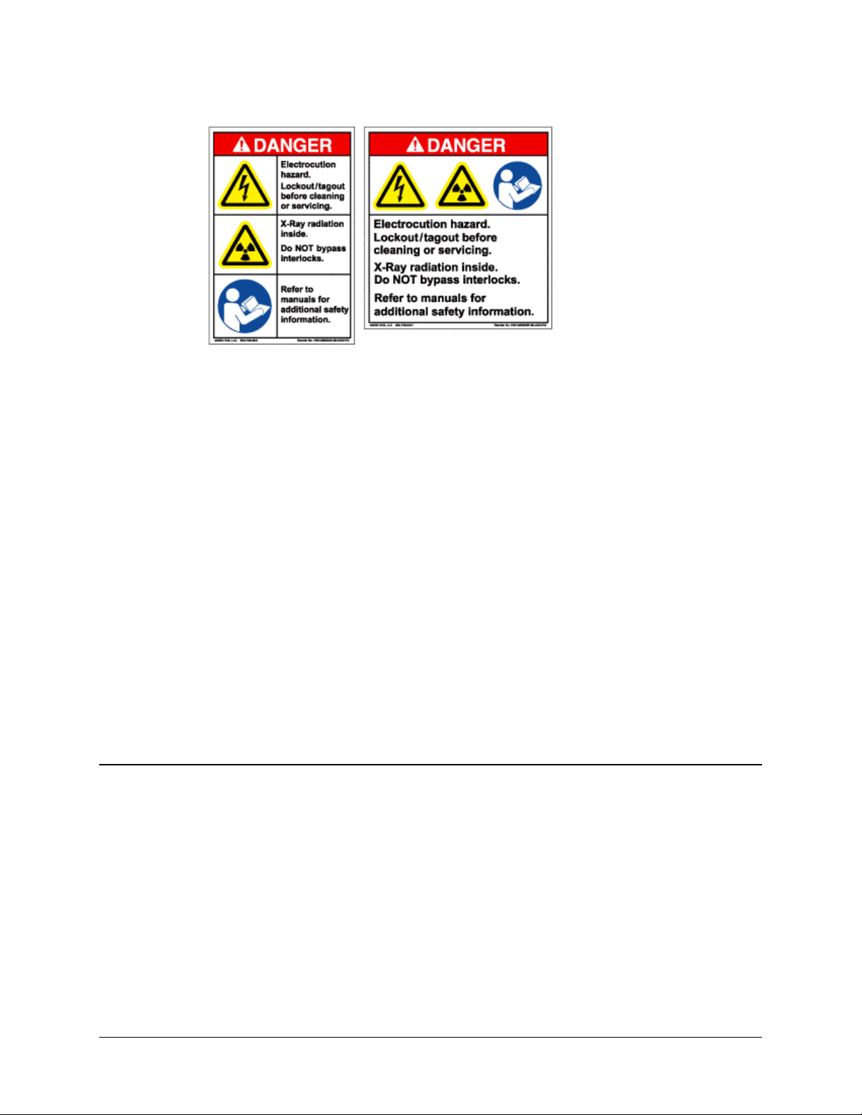
Examples of
Multi-Hazard Formats
Metric Conversion
Metric conversion information is located on the inside back cover of this manual. This
information is provided to assist the operator in cross-referencing non-Metric to Metric
conversions.
Recommended Standard Designations
Recommended Standard (RS) Designations are interchangeable with the designation of
the Electronic Industries Association (EIA).
Trademarks
Windows is a trademark of the Microsoft Corporation.
Other product names mentioned in this manual may be trademarks or registered
trademarks of their respective companies and are hereby acknowledged. Comtech EF
Data neither endorses nor otherwise sponsors any such production or services referred
herein.
Electromagnetic Compatibility (EMC) Compliance
This is a Class B product. In a domestic environment, it may cause radio interference that
requires the user to take adequate protection measures.
Emissions Compliance
This equipment has been tested and found to comply with the limits for a Class B digital
device, pursuant to Part 15 of the Federal Communications Commision (FCC) rules, and
EN55022 Class B requirements (pending).
These limits are designed to provide reasonable protection against harmful interference
when the equipment is operated in a commercial environment.
ix
Page 12
Digicast Media Router Serial IP (SIP): CMR-5910 (MG-SIP) & CMR-5920 (MR-SIP) Revision A
Preface MN/MDRTRIPDC.IOM
EN61000 Compliance
This equipment meets the EMC/immunity characteristics for the limits and methods of
measurement for information technology equipment as per EN61000-4-2, EN61000-4-3,
EN61000-4-4, EN61000-4-5 and EN61000-4-11 (pending).
This equipment meets the EMC/immunity characteristics for the limits and methods of
measurement of mains harmonics & flicker for information technology equipment as per
CE EN61000-3-2 and EN61000-3-3 (pending).
Safety Compliance
EN60950 Compliance
Applicable testing is routinely performed as a condition of manufacturing on all units to
ensure compliance with safety requirements of EN60950. This equipment meets the
Safety of Information Technology Equipment specification as defined in EN60950.
Low Voltage Directive (LVD)
The following information is applicable for the European Low Voltage Directive
(EN60950):
<HAR> Type of power cord required for use in the European Community.
!
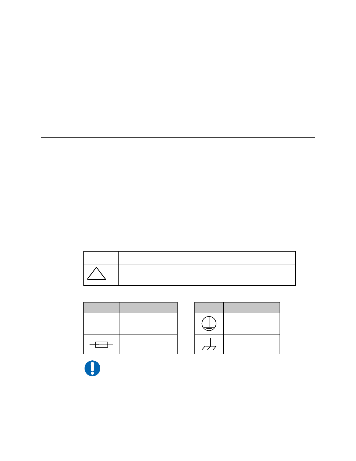
International Symbols:
Symbol Definition Symbol Definition
~
NOTE
CAUTION: Double-pole/Neutral Fusing
ACHTUNG: Zweipolige bzw. Neutralleiter-Sicherung
Alternating Current
For additional symbols, refer to Cautions and Warnings listed
earlier in this Preface.
Fuse
Protective Earth /
Safety Ground
Chassis Ground
x
Page 13

Digicast Media Router Serial IP (SIP): CMR-5910 (MG-SIP) & CMR-5920 (MR-SIP) Revision A
Preface MN/MDRTRIPDC.IOM
Warrant y Policy
Comtech EF Data products are warranted against defects in material and
workmanship for a period of two years from the date of shipment. During the
warranty period, Comtech EF Data will, at its option, repair or replace products
that prove to be defective.
For equipment under warranty, the owner is responsible for freight to Comtech EF
Data and all related customs, taxes, tariffs, insurance, etc. Comtech EF Data is
responsible for the freight charges only for return of the equipment from the factory
to the owner. Comtech EF Data will return the equipment by the same method (i.e.,
Air, Express, Surface) as the equipment was sent to Comtech EF Data.
All equipment returned for warranty repair must have a valid RMA number issued
prior to return and be marked clearly on the return packaging. Comtech EF Data
strongly recommends all equipment be returned in its original packaging.
Comtech EF Data Corporation’s obligations under this warranty are limited to
repair or replacement of failed parts, and the return shipment to the buyer of the
repaired or replaced parts.
Limitations of Warranty
The warranty does not apply to any part of a product that has been installed,
altered, repaired, or misused in any way that, in the opinion of Comtech EF Data
Corporation, would affect the reliability or detracts from the performance of any
part of the product, or is damaged as the result of use in a way or with equipment
that had not been previously approved by Comtech EF Data Corporation.
The warranty does not apply to any produ ct or parts thereof where the serial number
or the serial number of any of its parts has been altered, defaced, or removed.
The warranty does not cover damage or loss incurred in transportation of the product.
The warranty does not cover replacement or repair necessitated by loss or damage
from any cause beyond the control of Comtech EF Data Corporation, such as
lightning or other natural and weather related events or wartime environments.
The warranty does not cover any labor involved in the removal and or
reinstallation of warranted equipment or parts on site, or any labor required to
diagnose the necessity for repair or replacement.
The warranty excludes any responsibility by Comtech EF Data Corporation for
incidental or consequential damages arising from the use of the equipment or
xi
Page 14

Digicast Media Router Serial IP (SIP): CMR-5910 (MG-SIP) & CMR-5920 (MR-SIP) Revision A
Preface MN/MDRTRIPDC.IOM
products, or for any inability to use them either separate from or in combination
with any other equipment or products.
A fixed charge established for each product will be imposed for all equipment
returned for warranty repair where Comtech EF Data Corporation cannot identify
the cause of the reported failure.
Exclusive Remedies
Comtech EF Data Corporation’s warranty, as stated is in lieu of all other
warranties, expressed, implied, or statutory, including those of merchantability
and fitness for a particular purpose. The buyer shall pass on to any purchaser,
lessee, or other user of Comtech EF Data Corporation’s products, the
aforementioned warranty, and shall indemnify and hold harmless Comtech EF
Data Corporation from any claims or liability of such purchaser, lessee, or user
based upon allegations that the buyer, its agents, or employees have made
additional warranties or representations as to product preference or use.
The remedies provided herein are the buyer’s sole and exclusive remedies.
Comtech EF Data shall not be liable for any direct, indirect, special, incidental, or
consequential damages, whether based on contract, tort, or any other legal theory.
xii
Page 15

Chapter 1. INTRODUCTION
Figure 1-1. Digicast Serial IP MG-SIP / MR-SIP – Front Panels
CMR-5910
(MG-SIP)
CMR-5920
(MR-SIP)
1.1 Introduction
The Comtech EF Data (CEFD) CMR-5910 Digicast Media Router Serial IP
Gateway (MG-SIP) and CMR-5920 Serial IP Router (MR-SIP) – referred to respectively
throughout this manual as “the MG-SIP” or “the MR-SIP” – provide the end-points for
the transport of IP-formatted content (Tx for the MG-SIP, Rx for the MR-SIP) using the
HDLC protocol across an RS-422/RS-530 serial link.
The MG-SIP and MR-SIP provide an economical solution to upgrading legacy (non-IP
enabled) video networks, using Integrated Receiver Decoders (IRDs), to support
distribution of IP content to the collocated enterprise LAN.
1–1
Page 16

Digicast Media Router Serial IP (SIP): CMR-5910 (MG-SIP) & CMR-5920 (MR-SIP) Revision A
Introduction MN/MDRTRIPDC.IOM
1.2 Standard Features
Based on an embedded architecture utilizing a Freescale CPU and eCOS Operating
System, the MG-SIP and MR-SIP provide the following features:
• High Reliability
• Support for Multicast and Unicast IP datagrams
• HDLC Link-layer protocol
• Multicast Zones
• 64 Routes
• QoS on a route-by -route basis (min/max bandwidth)
• Support for IGMP and ICMP
• Aggregate throughput of 13.5 Mbps with 1,500 byte IP packets
• Color LEDs for status monitoring and rapid fault isolation
• Management (monitor, control and configuration):
o Web Interface
o SNMP V2 (Private and MIB II) Support (Future)
o TFTP for remote field software/firmware upgrade
o Terminal Interface
o Telnet
1.3 Performance
The MG-SIP and MR-SIP provide the following performance characteristics:
Item Value
Maximum Egress Rate Setting 13.5 Mbps
Maximum Bits Per Second (Maximum Packet Size 1,518 Bytes) 13.5 Mbps
Latency Less than 10 mS
1.4 Configuration
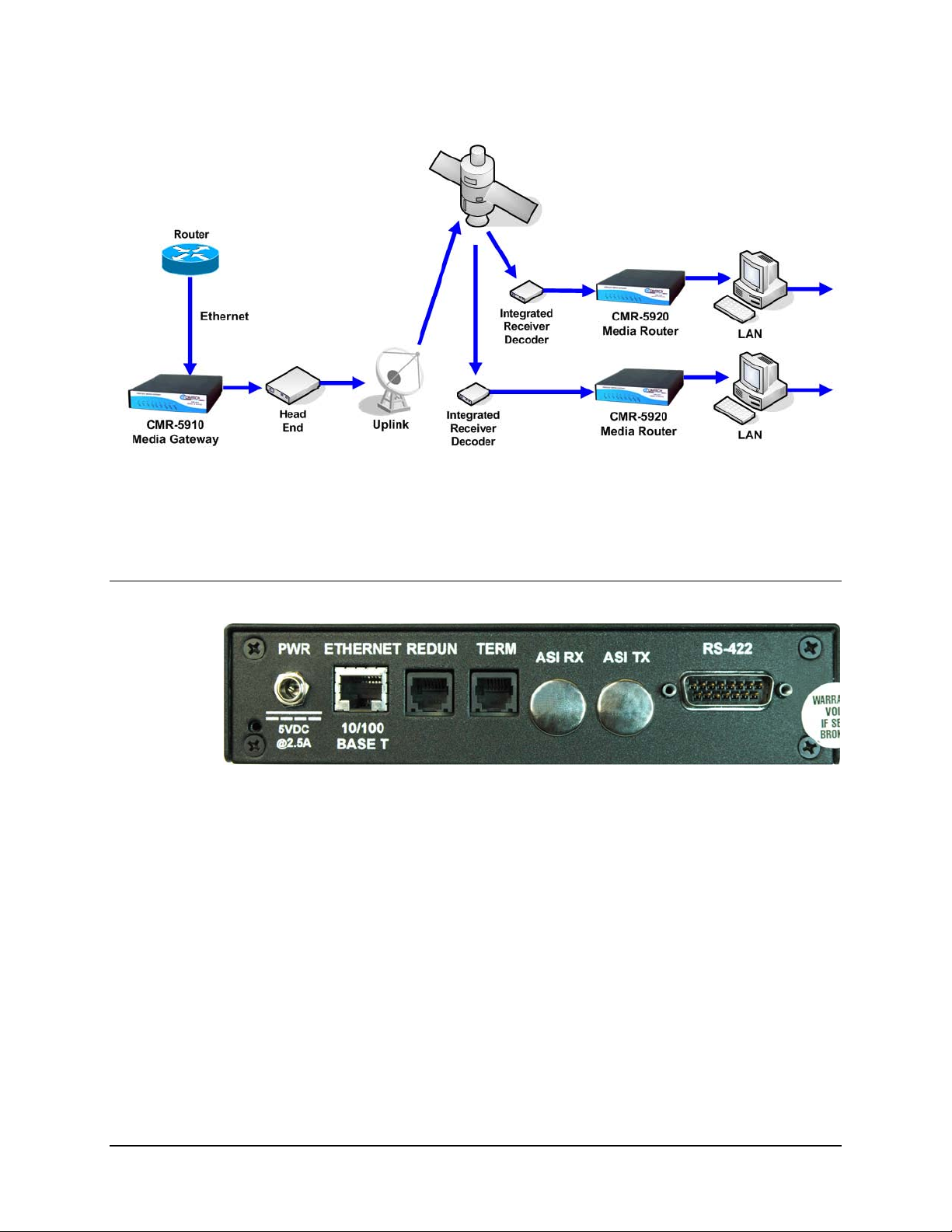
The MG-SIP and MR-SIP enable IP-based multimedia content (video, audio and data) to
be delivered over a high-speed RS-422 or RS-530 link and distributed to remote devices
connected via an Ethernet LAN, providing an inexpensive upgrade path for deployment
of an overlay distribution network across widely dispersed remote locations.
The capabilities of the MG-SIP and MR-SIP are depicted in Figure 1-2.
1–2
Page 17
Digicast Media Router Serial IP (SIP): CMR-5910 (MG-SIP) & CMR-5920 (MR-SIP) Revision A
Introduction MN/MDRTRIPDC.IOM
Figure 1-2. Digicast Serial IP MG-SIP / MR-SIP Operational Configuration
1.5 Specifications
Figure 1-3. Digicast Serial IP MG-SIP / MR-SIP – Rear Panel (typical)
1–3
Page 18

Digicast Media Router Serial IP (SIP): CMR-5910 (MG-SIP) & CMR-5920 (MR-SIP) Revision A
Introduction MN/MDRTRIPDC.IOM
Table 1-1. Digicast Serial IP MG-SIP / MR-SIP Specifications
Parameter Specification
Dimensions 7.125” L x 8.125” W x 1.72” H (18.1L x 20.6W x 4.4H cm)
Weight < 6 lbs (2.7 kg)
Power 2.5 mm with screw type connector
Physical
Electrical
Environmental
RS-422/RS-530
Interface
Ethernet
(10/100BaseT)
Terminal RJ-12
Redundancy
(future)
Blue PWR
Green RED
Red ALARM
Green SYNC
LEDs
Power Input /
Consumption
RS-422/RS-530 EIA
Ethernet
(10/100BaseT)
Console RS-232
Redundancy
(future)
Temperature
Operating
Storage
(Non-operating)
Humidity
Operating 10% to 75% Non-condensing
Storage
(Non-operating)
Altitude
Operating Up to 10,000 feet (3048 m) above sea level
Storage
(Non-operating)
Green E-SPD
Amber E-COL
Green E-RX
Green E-TX
Green E-LINK
15-pin Type D connector (male)
RJ-45
RJ-12
100 to 240 VAC 47-63 Hz converted to +5VDC @ 2.5A / < 7 W
IEEE 802.3u
RS-232
32° to 104° Farenheit (0° to 40° Celsius)
-22° to 150° Farenheit (-30° to 65° Celsius)
Relative humidity to 95% with temperature ≤ 95° Farenheit (35° Celsius)
Survival up to 50,000 feet (15240 m) above sea level for up to 15 hours
1–4
Page 19

Digicast Media Router Serial IP (SIP): CMR-5910 (MG-SIP) & CMR-5920 (MR-SIP) Revision A
Introduction MN/MDRTRIPDC.IOM
1.6 Terminology
The following table defines the acronyms referred to throughout this manual:
Acronym Definition
ASI
ARP
CEFD
DVB
DVB-S
DVB-S2
EBU
ETS
FTP
HDLC
HTML
HTTP
IANA
IGMP
IP
IRD
LAN
MAC
Mbps
MIB
MPE
MPEG
MPEGTS
MR
Msps
MUX
PID
RS
SNMP
SYSLOG
TCP
TERM
TFTP
TSD
UDP
VLAN
Asynchronous Serial Interface
Address Resolution Protocol
Comtech EF Data
Digital Video Broadcasting
Digital Video Broadcasting - Satellite
Digital Video Broadcasting - Satellite (Second Generation)
European Broadcasting Union
European Telecommunications Standard
File Transfer Protocol
High-level Data Link Control
Hypertext Markup Language
HyperText Transport Protocol
Internet Assigned Number Authority
Internet Gateway Messaging Protocol
Internet Protocol
Integrated Receiver Decoder
Local Area Network
Media Access Control
Mega bits per second
Management Information Base
Multi-Protocol Encapsulation
Moving Pictures Expert Group
Moving Pictures Expert Group Transport System
Media Router
Million samples per second
Multiplexer
Packet Identifier
Reed Solomon
Simple Network Management Protocol
System Log
Transmission Control Protocol
Terminal
Trivial File Transfer Protocol
Transport Stream Demultiplexer
User Datagram Protocol
Virtual Local Area Network
1–5
Page 20

Digicast Media Router Serial IP (SIP): CMR-5910 (MG-SIP) & CMR-5920 (MR-SIP) Revision A
Introduction MN/MDRTRIPDC.IOM
Notes:
1–6
Page 21

Chapter 2. INSTALLATION &
INITIAL CONFIGURATION
2.1 Major Assembly
The MG-SIP and MR-SIP are available in standalone configurations. Table 2-1 lists the
components provided with a standard configuration. In the event any listed item is
missing, please contact Comtech EF Data Customer Support:
Table 2-1. Digicast Serial IP – Standalone Configuration
Quantity Description
1
1 SPU24-102 Power Supply
1 IEC Power Cable
1 CA-TERMINAL Terminal Cable
1 CD (includes this manual and the Quick Start reference)
1 Quick Start sheet
2.2 Unpacking
The shipping container and packing materials should be retained for possible reshipment.
Perform a receiving inspection as follows:
• Inspect the shipping container for damage. If there is damage to the shipping
• Check to determine that all parts, materials and documentation have been
• Inspect the device for possible physical damage.
• Test the device for proper operation.
Digicast Media Router Serial IP:
CMR-5910 Serial IP Gateway (MG-SIP) OR
CMR-5920 Serial IP Router (MR-SIP)
container,
shipped with the device.
notify the carrier.
2-1
Page 22
Digicast Media Router Serial IP (SIP): CMR-5910 (MG-SIP) & CMR-5920 (MR-SIP) Revision A
Installation & Initial Configuration MN/MDRTRIPDC.IOM
• Contact Comtech EF Data Customer Support if the shipment is:
! Incomplete
! Physically damaged
! Inoperable
2.3 Installation
The MG-SIP and MR-SIP are designed for ease of installation and configuration.
Once the device has been removed from the packing container, follow these
instructions:
Step Procedure
1 Place the device on a flat surface with free-air flow where the LEDs can be
clearly observed with unrestricted access to the rear panel of the device.
2 Connect the DC power connection to the connection labeled PWR on the back
of the device and tighten the restraining nut to ensure secure operation.
3 Connect an RJ-45 Ethernet cable (patch cord) to the port labeled ETHERNET.
This cable should be connected to an Ethernet concentrator (hub) or switch.
4 Connect a terminal cable (supplied) to the port labeled TERM. This cable
should be connected to a PC’s serial port (DB-9) to initially configure the IS.
5 Connect the AC power cord between a standard wall outlet and the power
supply. The blue LED will illuminate.
The port labeled REDUN is currently not supported.
6
IMPORTANT
7 Upon startup, the LEDs on the device front panel become operational as follows:
LED
Blue
Green
Red
Green
Amber
Green
Green
Green
It is recommended that the RS-422/RS-530 cable NOT be
connected until after the device has been completely configured.
Function
Label
PWR
RED
ALARM
SYNC
E-COL
E-RX
E-TX
E-LINK
Description
LED illuminates if power is properly applied
LED will not illuminate – reserved for future
redundancy functionality
LED may illuminate since the device is not yet
configured
LED illuminates if traffic is being routed to the
RS-422 interface
LED flashes if there are collisions on the
Ethernet switch
LED flashes if there is activity on the switch
LED flashes if the device is transmitting data to
the Ethernet
LED illuminates if the Ethernet connection to
the Hub/Switch is operational
2-2
Page 23

Digicast Media Router Serial IP (SIP): CMR-5910 (MG-SIP) & CMR-5920 (MR-SIP) Revision A
Installation & Initial Configuration MN/MDRTRIPDC.IOM
2.4 Initial Configuration
The initial configuration involves setting up the IP parameters via the terminal cable.
Once the IP parameters have been configured, the terminal cable can be removed. The
terminal cable should be stored in a known location, since it may be needed in the future.
To configure the IP parameters:
Step Procedure
1 Using a terminal emulator on a PC such as HyperTerminal™ or
TeraTerm™, set up the communication port as follows:
• 38,400 BAUD
• 8 Data Bits
• 1 Stop Bit
• No Parity
• No Flow Control
2 Press the <ENTER> key on the PC – the device’s menu should be
displayed.
3 Press “N” for Network Menu.
4 Press “I” for the IP Address. Enter the IP Address and select <ENTER>.
5 Press “M” for the Subnet Mask. Enter the Subnet Mask and press
<ENTER>.
6 Press “G” for the Default Gateway IP Address. Enter the Default
Gateway Address and press <ENTER>.
7 Press “S” to save the parameters.
8 Press “Y” to confirm the saving of parameters.
9 Press “X” to exit to the main menu.
For the MG-SIP only:
10 Press “E” to configure the egress port.
11 Press “M” to configure the egress clock source as external or internal.
12 Press “R” to configure the egress clock rate in bits per second (bps) and
press <ENTER>.
13 Press “S” to save the parameters.
14 Press “Y” to confirm the saving of parameters.
15 Press “X” to exit the menu.
At this point, the device has been configured for full operation and the terminal cable
may be removed. The RS-422/RS-530 cable may now be safely attached to the DB-15
male connector marked
the Terminal Interface; however, it is recommended to use the Web Interface for ease of
management.
RS-422. For continued operation, the device may be managed via
2-3
Page 24

Digicast Media Router Serial IP (SIP): CMR-5910 (MG-SIP) & CMR-5920 (MR-SIP) Revision A
Installation & Initial Configuration MN/MDRTRIPDC.IOM
Notes:
2-4
Page 25
Chapter 3. INTERFACE PINOUTS
3.1 Pinout Overview
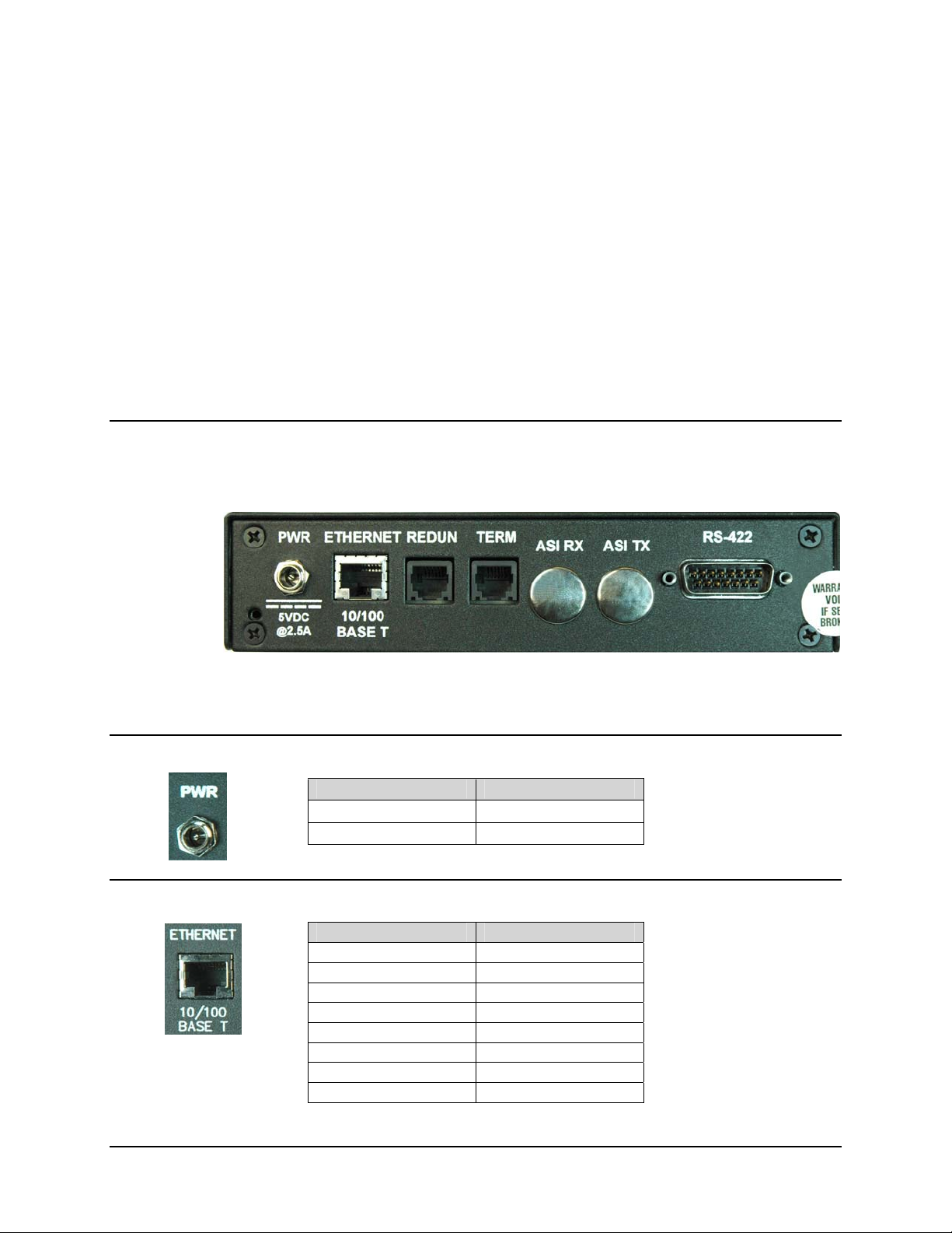
The rear panel interface (Figure 3-1) provides all necessary external connections between
the MG-SIP or MR-SIP and other equipment.
Figure 3-1. Digicast Serial IP MG-SIP / MR-SIP – Rear Panel (typical)
3.2 DC Power
Pin Definition
Center +5VDC
Outer Ring GND
3.3 RJ-45 Ethernet
Pin Definition
1 TXD+
2 TXD3 RXD+
4 N/C
5 N/C
6 RXD7 N/C
8 N/C
3-1
Page 26

Digicast Media Router Serial IP (SIP): CMR-5910 (MG-SIP) & CMR-5920 (MR-SIP) Revision A
Interface Pinouts MN/MDRTRIPDC.IOM
3.4 RJ-12 Redundancy (future)
Pin Definition
1 GND
2 TXD
3 RXD
4 GND
5 N/C
6 N/C
3.5 RJ-12 Terminal
Pin Definition
1 GND
2 TXD
3 RXD
4 GND
5 N/C
6 N/C
3.6 RS-422
Pin Definition
1 GND
2 N/C
3 N/C
4 ETxCB(-)
5 TxCB(-)
6 TxDA(-)
7 RxCB(-)
8 RxDB(-)
9 Signal Ground
10 N/C
11 ETxCA(+)
12 TxCA(+)
13 TxDA(+)
14 RxCA(+)
15 RxDA(+)
3-2
Page 27

Chapter 4. DEVICE MANAGEMENT
VIA USER INTERFACES:
CMR-5910 (MG-SIP)
4.1 Introduction
Management of the CMR-5910 Serial IP Gateway (MG-SIP) is simple and intuitive. This
chapter outlines the variety of ways to specifically configure and manage the MG-SIP:
• Web Interface via a LAN-based desktop Web browser
• Terminal Interface via direct connection to a PC’s asynchronous serial port
• Telnet Interface via a LAN
• TFTP for remote terminal upgrades
• SNMP Private MIB and MIB II (Future)
4.2 Web Interface
The Web Interface, operating under standard HyperText Transport Protocol (HTTP), is
used to communicate with and command the MG-SIP via a HyperText Markup
Language-based Graphical User Interface (GUI). To utilize the Web Interface, a LAN
connection must exist between the PC with a Web browser and the MG-SIP.
Once a valid IP Address, Subnet Mask and Defa ult Ga tewa y have be en entered into the
MG-SIP, activate a Web browser on the desktop, then enter the MG-SIP’s IP address into the
URL field as shown below. If t he port num ber has bee n m odified from the Standard 80 via
the Terminal Interface, then the port number must be appende d with a colon to the IP address .
Figure 4-1. Connecting to the MG-SIP
4-1
Page 28
Digicast Media Router Serial IP (SIP): CMR-5910 (MG-SIP) & CMR-5920 (MR-SIP) Revision A
Device Management via User Interfaces - CMR-5910 (MG-SIP) MN/MDRTRIPDC.IOM
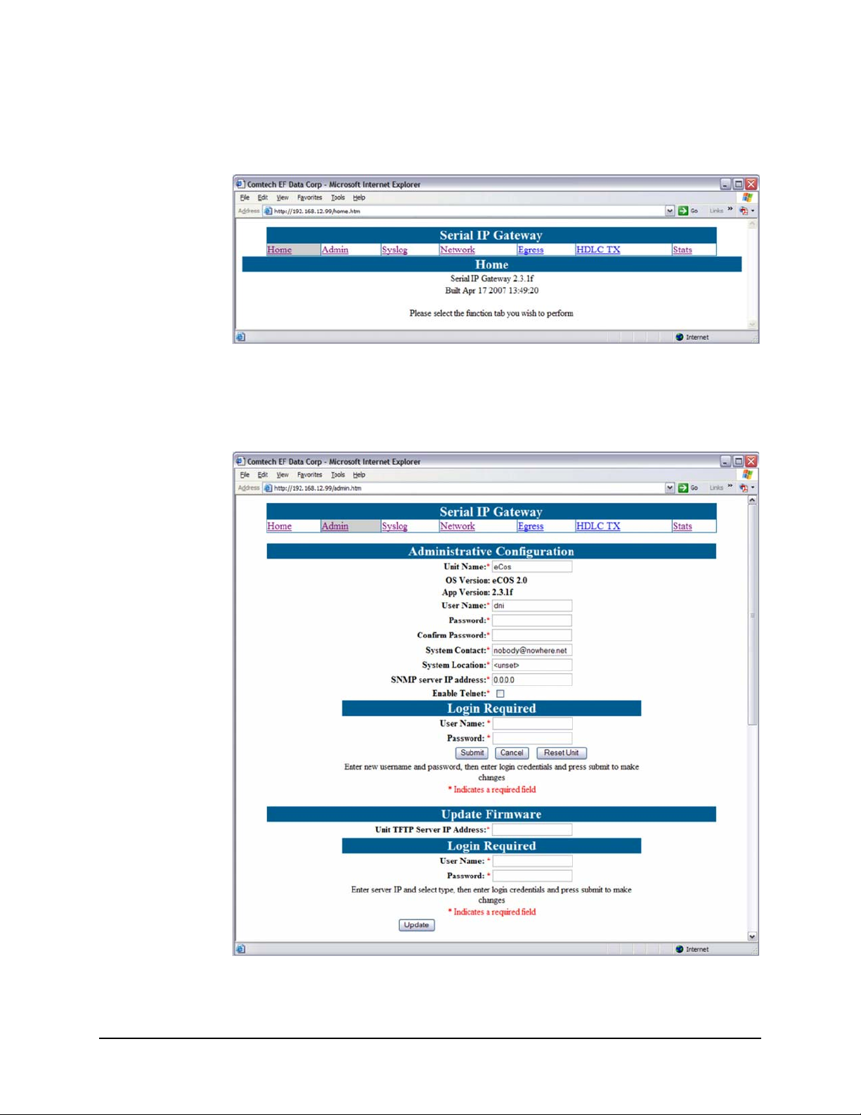
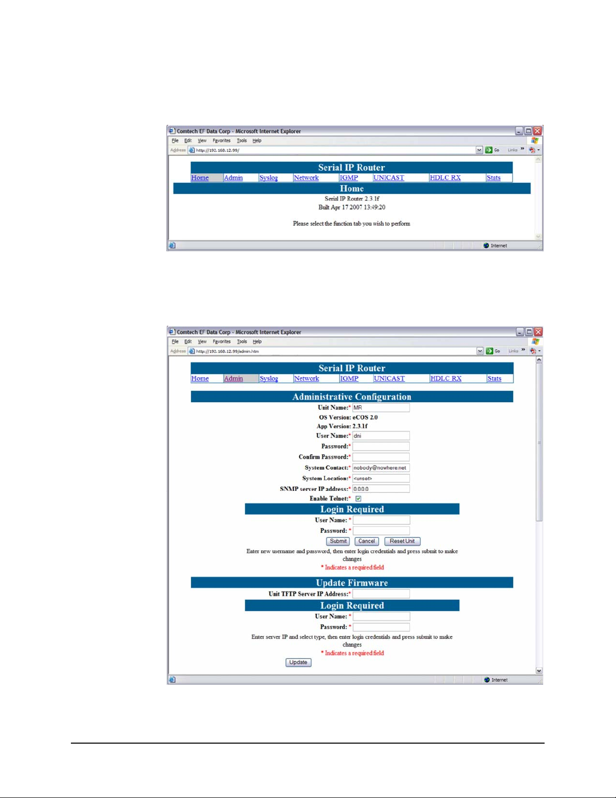
If there is a connection between the PC and the MG-SIP, the response from the MG-SIP
will be the “splash page” as shown in
Figure 4-2.
Figure 4-2. MG-SIP Home (“Splash”) page
4.2.1 Administrative Configuration
Figure 4-3. Administrative Configuration page
4-2
Page 29

Digicast Media Router Serial IP (SIP): CMR-5910 (MG-SIP) & CMR-5920 (MR-SIP) Revision A
Device Management via User Interfaces - CMR-5910 (MG-SIP) MN/MDRTRIPDC.IOM
NOTE
Beginning with the Administrative Configuration page, for pages
featuring configurable parameters, changes will not be accepted
without a valid user name and password. A login dialog box is
available at the bottom of the page for this purpose.
The Administrative Configuration page (
User Name
The User Name is user configurable and is used for connecting to the unit via IP
management services.
The default User Name is
Password
The Password is user configurable and is used for authenticating a user when
connecting via IP management services. Note the password is case sensitive and
must be entered carefully. When the password is changed, the user will be
prompted to enter the password twice to verify it is correct.
The default Password is
System Contact
Contact information of the system administrator for support.
System Location
The location (physically) where the unit has been installed.
SNMP server IP Address
Defines the SNMP server that can connect to the unit.
Enable Telne
Enables Telnet application on the MG-SIP.
Login Required
To make any changes to the MG-SIP, a user name & password are required.
Update Firmware
Allows software/firmware changes to be made. User name & password is
required for security.
t
Figure 4-3) has the following configurable parameters:
comtech.
comtech.
4-3
Page 30

Digicast Media Router Serial IP (SIP): CMR-5910 (MG-SIP) & CMR-5920 (MR-SIP) Revision A
Device Management via User Interfaces - CMR-5910 (MG-SIP) MN/MDRTRIPDC.IOM
4.2.2 Syslog Configuration
Figure 4-4. Syslog Configuration page
Syslog is a common feature of the Linux operating system. Syslog allows the events that
occur on the MG-SIP to be sent to a server where they can be logged. The events are
delivered to a configured server over Ethernet IP.
Enable
Enables or disables the Syslog feature.
IP Address
The IP address of the Syslog server.
Port
The port of the Syslog server. The default port number is
514.
4-4
Page 31

Digicast Media Router Serial IP (SIP): CMR-5910 (MG-SIP) & CMR-5920 (MR-SIP) Revision A
Device Management via User Interfaces - CMR-5910 (MG-SIP) MN/MDRTRIPDC.IOM
4.2.3 Network Configuration
Figure 4-5. Network Configuration page
The Network Configuration page has the following configurable parameters:
IP Address
The IP Address assigned to the MG-SIP LAN interfaces. The IP Address is
entered in dotted decimal format.
Subnet Mask
The Subnet Mask assigned to the MG-SIP LAN interface. The Subnet Mask is
entered in dotted decimal format and is typically 255.0.0.0 for an A-Class mask,
255.255.0.0 for a B-Class mask, or 255.255.255.0 for a C-Class mask.
Default Gateway
The Default Gateway assigned to the MG-SIP LAN interface is the address of a
local router to which all non-local subnet traffic will be directed. The Default
Gateway is entered in dotted decimal format and must be with in the subnet of
the IP Address assigned to the LAN interface.
4-5
Page 32

Digicast Media Router Serial IP (SIP): CMR-5910 (MG-SIP) & CMR-5920 (MR-SIP) Revision A
Device Management via User Interfaces - CMR-5910 (MG-SIP) MN/MDRTRIPDC.IOM
4.2.4 HDLC Egress Configuration
Figure 4-6. HDLC Egress Configuration page
The HDLC Egress Configuration page has the following configurable parameters:
Mode
Configure the unit for internal clock (provided to the network) or external clock
(provided by the network).
Clock Rate
Sets the bit rate of the HDLC Egress interface in Mbps. The MG-SIP supports
egress clock rates from 64 Kbps to 13.5 Mpbs in steps of 1 bps.
Actual Clock Rate
The dervied rate for internal clock.
4-6
Page 33

Digicast Media Router Serial IP (SIP): CMR-5910 (MG-SIP) & CMR-5920 (MR-SIP) Revision A
Device Management via User Interfaces - CMR-5910 (MG-SIP) MN/MDRTRIPDC.IOM
4.2.5 (HDLC TX) Route Configuration
Figure 4-7. (HDLC TX) Route Configuration page
The Route Configuration page supports up to 64 Multicast or Unicast routes.
Page Up
and Page Down allow the user to scroll up or down through the configured routes on the
MG-SIP. Once a route has been added or edited, the
Submit button must be pressed to
make the change permanent. An advanced link is present on the page to allow the QoS
parameters to be set.
The MG-SIP has the following configurable parameters:
On
The route is enabled when checked.
Name
The name assigned to a given route.
IP Address
The IP Address assigned to a given route. Note a unicast route will fall within the
range 0.0.0.0 to 223.255.255.255 (excluding broadcast or reserved IP addresses),
and a multicast route will fall within the range of 224.0.0.0 to 239.255.255.255.
Subnet Mask (SM)
The Subnet Mask, or SM, defines the range of IP addresses that will be supported
by a particular route. It is represented by a 32-bit string of 1’s (representing the
network and subnet network ID) followed by 0’s (representing the host ID). This
4-7
Page 34

Digicast Media Router Serial IP (SIP): CMR-5910 (MG-SIP) & CMR-5920 (MR-SIP) Revision A
Device Management via User Interfaces - CMR-5910 (MG-SIP) MN/MDRTRIPDC.IOM
string when logically ‘ANDED’ with the IP address, defines the network/subnet
IP address.
The following demonstrates how the subnet mask defines the IP address range.
The MG-SIP use Classless Inter-Domain Routing (CIDR) notation for setting the
subnet masks.
• 255.255.255.255 is 0 bits
(used for an explicit route for a single IP address)
• 255.0.0.0 is 8 bits (used for an A-Class Mask)
• 255.255.0.0 is 16 bits (used for a B-Class Mask)
• 255.255.255.0 is 24 bits (used for a C-Class Mask)
HDLC Address
The HDLC address is assigned to a particular route. HDLC addresses do not have
to be unique and may be assigned to one or more routes.
MAC Address
The MAC address assigned to a given route. For Unicast, this is typically the
MAC address the route is assigned to and is determined by the end device (nexthop) to which the data is to be sent. However, for Multicast, this is derived as
described previously.
Guaranteed Bandwidth
The guaranteed bandwidth offered to a given route. The route will be guaranteed
a minimum of this amount of bandwidth on the MG-SIP.
Max Bandwidth
The maximum bandwidth allowed for a given route. Any traffic that exceeds the
maximum bandwidth will be silently discarded.
4-8
Page 35

Digicast Media Router Serial IP (SIP): CMR-5910 (MG-SIP) & CMR-5920 (MR-SIP) Revision A
Device Management via User Interfaces - CMR-5910 (MG-SIP) MN/MDRTRIPDC.IOM
4.2.6 Statistics
Figure 4-8. Uplink Route Statistics page
The Uplink Route Statistics page displays the statistics for all configured routes.
and
Down allows the user to scroll up or down through the configured routes on the
MG-SIP.
The
Clear Stats button allows all statistics to be cleared on the MG-SIP at the same time.
On
‘Yes’ indicates the route is active.
Name
The name assigned to a given route.
Received
The number of IP packets received on this route since the statistics were last
cleared.
Dropped
The number of IP packets dropped on this route since the statistics were last
cleared.
HDLC
The address assigned to the associated route.
Page Up
4-9
Page 36

Digicast Media Router Serial IP (SIP): CMR-5910 (MG-SIP) & CMR-5920 (MR-SIP) Revision A
Device Management via User Interfaces - CMR-5910 (MG-SIP) MN/MDRTRIPDC.IOM
Min
The minimum bandwidth received on this route since the statistics were last
cleared.
Max
The maximum bandwidth received on this route since the statistics were last
cleared.
Average
The average bandwidth received on this route.
4-10
Page 37

Digicast Media Router Serial IP (SIP): CMR-5910 (MG-SIP) & CMR-5920 (MR-SIP) Revision A
A
Device Management via User Interfaces - CMR-5910 (MG-SIP) MN/MDRTRIPDC.IOM
4.3 Terminal Interface
The Terminal Interface provides the user with a textual configuration dialog for
configuring the MG-SIP. This method of configuration should be used for initial
configuration of the unit – i.e., configuring the network parameters for the unit, but not
for normal operation. The Web (HTTP) Interface is recommended for operational
management.
The Terminal Interface allows the entire unit to be configured a nd managed, but this interface
can only be used while a serial connection is present between the MG-SIP and a PC. While
the same menu information is displayed via the Telnet interface, there are specific
features available only via the ‘serial interface’ access method – these ‘serial interface
only’ features are noted in this section.
Figure 4-9 shows the hierarchal structure of the Terminal Interface-based menus, and the
sections in this chapter which provide figures of these submenu pages.
Main Menu
(4.3.1)
dministration
Menu (4.3.2)
HLDC Configuration
Menu (4.3.3)
Egress Menu
(4.3.4)
Stats Menu
(4.3.5)
Network Menu
(4.3.6)
(Uplink) HDLC Route
Config (4.3.3.1)
HDLC Advanced Route
Conf ig (4 .3.3.1.1)
HDLC Uplink Stats
(4.3.5.1)
Ethernet Stats
(4.3.5.2)
Figure 4-9. Menu Hierarchy (via Terminal Interface)
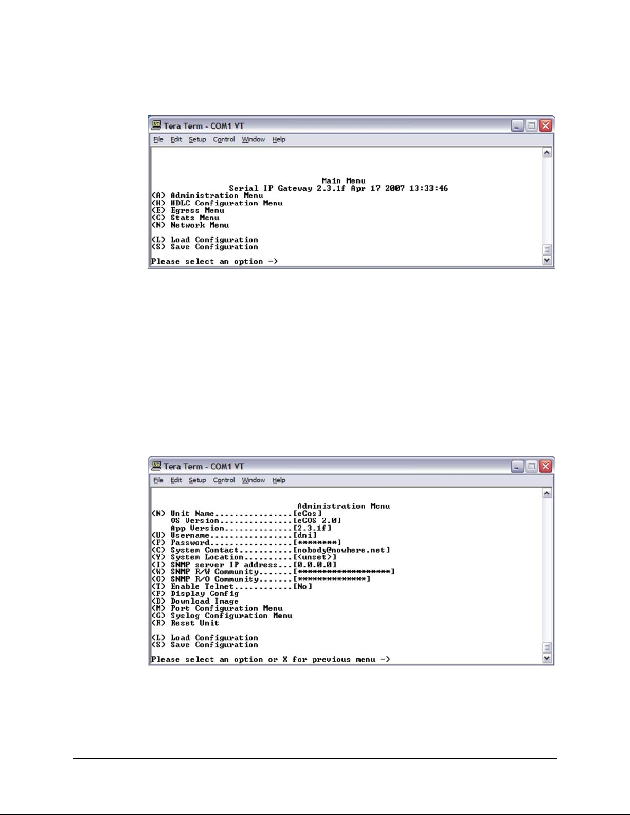
Once the terminal interface is connected, as described in Chapter 2.4 Initi al C onfigurat ion,
press the
<ENTER> key. Th e user sho uld observe the the Main Men u, shown in Figure 4-10.
4-11
Page 38
Digicast Media Router Serial IP (SIP): CMR-5910 (MG-SIP) & CMR-5920 (MR-SIP) Revision A
Device Management via User Interfaces - CMR-5910 (MG-SIP) MN/MDRTRIPDC.IOM
4.3.1 Main Menu
Figure 4-10. Main Menu
4.3.2 Administration Menu
Figure 4-11. Administration Menu
4-12
Page 39
Digicast Media Router Serial IP (SIP): CMR-5910 (MG-SIP) & CMR-5920 (MR-SIP) Revision A
Device Management via User Interfaces - CMR-5910 (MG-SIP) MN/MDRTRIPDC.IOM
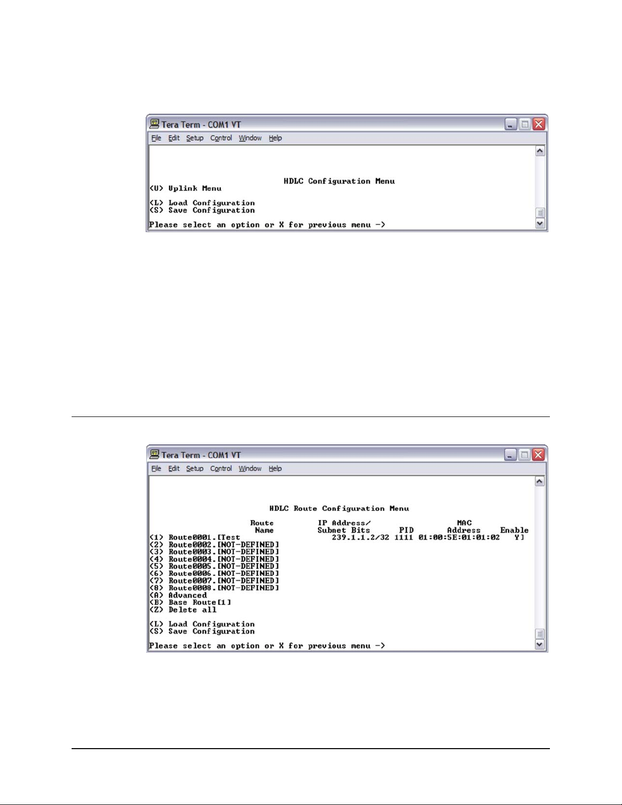
4.3.3 HDLC Configuration Menu
Figure 4-12. HDLC Configuration Menu
4.3.3.1 (Uplink) HDLC Route Configuration Menu
Figure 4-13. (Uplink) HDLC Route Configuration Menu
4-13
Page 40

Digicast Media Router Serial IP (SIP): CMR-5910 (MG-SIP) & CMR-5920 (MR-SIP) Revision A
Device Management via User Interfaces - CMR-5910 (MG-SIP) MN/MDRTRIPDC.IOM
4.3.3.1.1 HDLC Advanced Route Configuration Menu
Figure 4-14. HDLC Advanced Route Configuration Menu
4.3.4 Egress Configuration Menu
Figure 4-15. Egress Configuration Menu
4-14
Page 41
Digicast Media Router Serial IP (SIP): CMR-5910 (MG-SIP) & CMR-5920 (MR-SIP) Revision A
Device Management via User Interfaces - CMR-5910 (MG-SIP) MN/MDRTRIPDC.IOM
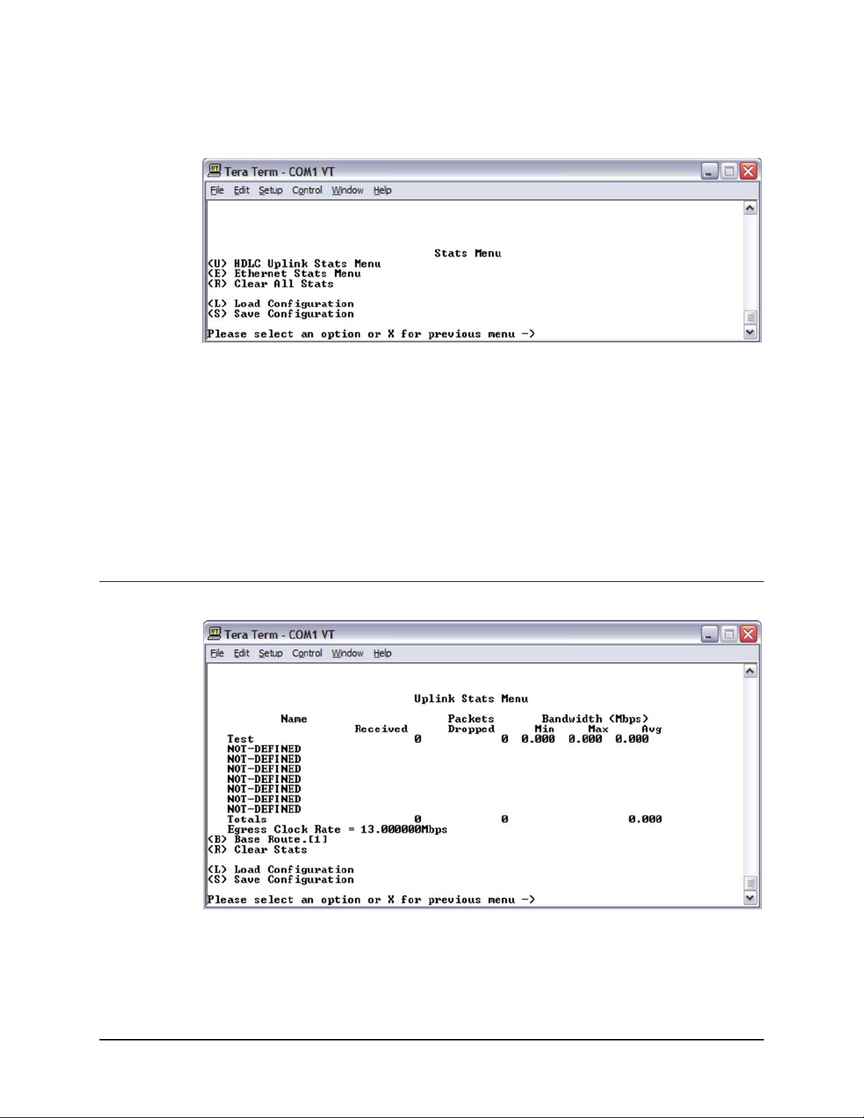
4.3.5 Stats (Statistics) Menu
Figure 4-16. Stats Menu
4.3.5.1 HDLC Uplink Stats Menu
Figure 4-17. HDLC Uplink Stats Menu
4-15
Page 42
Digicast Media Router Serial IP (SIP): CMR-5910 (MG-SIP) & CMR-5920 (MR-SIP) Revision A
Device Management via User Interfaces - CMR-5910 (MG-SIP) MN/MDRTRIPDC.IOM
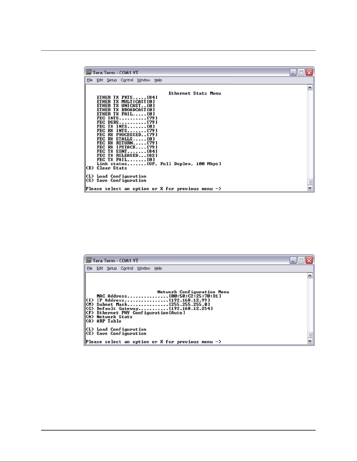
4.3.5.2 Ethernet Stats Menu
Figure 4-18. Ethernet Stats Menu
4.3.6 Network Configuration Menu
Figure 4-19. Network Configuration Menu
4-16
Page 43

Digicast Media Router Serial IP (SIP): CMR-5910 (MG-SIP) & CMR-5920 (MR-SIP) Revision A
Device Management via User Interfaces - CMR-5910 (MG-SIP) MN/MDRTRIPDC.IOM
4.4 Telnet Interface
Telnet provides a textual interface over a LAN. Most PCs have the capability to use
Telnet. To use Telnet on a Microsoft Windows
The dialog is shown in
where
xxx.xxx.xxx.xxx is the IP address of the MG-SIP. If the port number has been
Figure 4-20. In the Open dialog, enter “telnet xxx.xxx.xxx.xxx”
®
product, click , then .
modified from the Standard 23 via the Terminal Interface, then the port number must be
appended with a colon to the IP address.
Figure 4-20. Starting Telnet Session
The user will be prompted to enter the user name and password to gain access to the
telnet interface.
NOTE
The default username is comtech and the default password is
comtech, both of which are case sensitive.
Once the menu is started, press
displayed as shown in
Figure 4-21.
<ENTER> and the main menu of the MG-SIP be
Figure 4-21. Main Menu via Telnet
The user may navigate the menus in the same manner as the Terminal Interface. With
specific exceptions as noted in the Terminal Interface section, the menus available via
Telnet and Serial interfaces are identical.
4-17
Page 44

Digicast Media Router Serial IP (SIP): CMR-5910 (MG-SIP) & CMR-5920 (MR-SIP) Revision A
T
T
Device Management via User Interfaces - CMR-5910 (MG-SIP) MN/MDRTRIPDC.IOM
4.5 Trivial File Transfer Protocol (TFTP)
The MG-SIP support changes to the resident software and firmware by means of the
Trivial File Transfer Protocol (TFTP). This enables changes to be made remotely via the
LAN interface. It is recommended to use Solarwinds TFTP server application (available
at
http://support.solarwinds.net/updates/SelectProgramFree.cfm).
To modify the software and/or firmware, use the following procedures:
Configure the server as follows:
File ! Configuration ! Select the ‘TFTP Root Directory’. Set up the location
a)
of the MG-SIP files.
b)
File ! Configuration ! Select the ‘Security’ tab and make sure ‘Transmit and
Receive
c) Save configuration.
The server is now configured for the file transfer process.
IMPORTAN
To modify code via Telnet:
’ are selected.
Because the MG-SIP stops processing data traffic during the
download process, it is recommended that this upgrade procedure be
performed during scheduled network down time.
Do NOT remove power from the unit during the download process.
Step Procedure
1 Start up Solarwinds TFTP server – Ensure configuration as described
previously.
2 Ensure that the code provided by CEFD is located in the TFTP Root
directory.
3 Start up Telnet client and initiate a session with the MG-SIP as
described in the Terminal Interface section.
4 Select ‘A’ for Administrative.
5 Select ‘D’ for Download.
6 Enter the IP address of the TFTP server and wait for the message
“Upgrade complete. Press any key to continue.”
This code modification process can also be conducted via the Web Interface, under the
Administrative page, or the Terminal Interface under the Main Menu.
IMPORTAN
Under heavy traffic conditions, the TFTP transfer may take several
minutes. The transfer process reported by Solarwinds may show
greater than 100% transferred, but this is a normal condition. Be
patient and allow the transfer to take place.
4-18
Page 45

Digicast Media Router Serial IP (SIP): CMR-5910 (MG-SIP) & CMR-5920 (MR-SIP) Revision A
Device Management via User Interfaces - CMR-5910 (MG-SIP) MN/MDRTRIPDC.IOM
4.6 Simple Network Management Protocol (SNMP)
Simple Network Management Protocol (SNMP) has not been enabled on this product and
is planned as a future release. However, when enabled, SNMP allows an SNMP Manager
such as OpenView or Castle Rock to be used to remotely manage the MG-SIP in an
automated fashion.
The MG-SIP supports SNMP versions 1 and 2 (SNMPv1 and SNMPv2). SNMP version
3 (SNMPv3) will be supported in future releases. Two types of Management Information
Bases (MIBs) are supported: MIB II and private MIB.
MIB II is the default MIB used to gather generic information about the unit, such as
system ‘up’ time, packets sent or received on an interface, etc. MIB II is designed for
only read access, not write access. To read and write configuration parameters over
SNMP requires a private MIB. The private MIB allows parameters to be set on the
Web, Terminal, or Telnet interfaces.
The elements Object Identifiers (OIDs) of the MIB will be listed in the appendix of a
future revision of this manual. CEFD has been assigned an SNMP designator by the
IEEE, which will be found in all elements of the MG-SIP’s MIB.
NOTE
The assigned designator for CEFD (enterprise OID) is 1.3.6.4.1.18723.
The MG-SIP support configurable community strings for added security. Note passwords
cannot be remotely queried over SNMP as a security precaution.
For SNMP access from a remote network via the public Internet, a VPN connection to the
MG-SIP will need to be established using third-party VPN client/server access.
The default community string for the public elements is
community string is
private.
public and the private
4-19
Page 46

Digicast Media Router Serial IP (SIP): CMR-5910 (MG-SIP) & CMR-5920 (MR-SIP) Revision A
Device Management via User Interfaces - CMR-5910 (MG-SIP) MN/MDRTRIPDC.IOM
Notes:
4-20
Page 47

Chapter 5. DEVICE MANAGEMENT
VIA USER INTERFACES:
CMR-5920 (MR-SIP)
5.1 Introduction
Management of the CMR-5920 Serial IP Router (MR-SIP) is simple and intuitive. There
are a variety of ways to specficially configure and manage the MR-SIP:
• Web Interface via a LAN-based desktop Web browser
• Terminal Interface via direct connection to a PC’s asynchronous serial port
• Telnet Interface via a LAN
• TFTP for remote terminal upgrades
• SNMP Private MIB and MIB II (Future)
5.2 Web Interface
The Web Interface, operating under standard HyperText Transport Protocol (HTTP), is
used to communicate with and command the MR-SIP via a HyperText Markup
Language-based Graphical User Interface (GUI). To utilize the Web Interface, a LAN
connection must exist between the PC with a Web browser and the MR-SIP.
Once a valid IP Address, Subnet Mask and Default Gateway have been entered into the
MR-SIP, activate a Web browser on the desktop then enter the IP address of the MR-SIP
into the URL field as shown below. If the port number has been modified from the
Standard 80 via the Terminal Interface, then the port number must be appended with a
colon to the IP address.
Figure 5-1. Connecting to the MR-SIP
5-1
Page 48
Digicast Media Router Serial IP (SIP): CMR-5910 (MG-SIP) & CMR-5920 (MR-SIP) Revision A
Device Management via User Interfaces - CMR-5920 (MR-SIP) MN/MDRTRIPDC.IOM
If there is a connection between the PC and the MR-SIP, the response from the MR-SIP
will be the “splash page” as shown in
Figure 5-2.
Figure 5-2. MR-SIP Home (“Splash”) page
5.2.1 Administrative Configuration
Figure 5-3. Administrative Configuration page
5-2
Page 49

Digicast Media Router Serial IP (SIP): CMR-5910 (MG-SIP) & CMR-5920 (MR-SIP) Revision A
Device Management via User Interfaces - CMR-5920 (MR-SIP) MN/MDRTRIPDC.IOM
NOTE
Beginning with the Administrative Configuration page, for pages
featuring configurable parameters, changes will not be accepted
without a valid user name and password. A login dialog box is
available at the bottom of the page for this purpose.
The Administrative Configuration page (
User Name
The User Name is user configurable and is used for connecting to the unit via IP
management services.
The default User Name is
Password
The Password is user configurable and is used for authenticating a user when
connecting via IP management services. Note the password is case sensitive and
must be entered carefully. When the password is changed, the user will be
prompted to enter the password twice to verify it is correct.
The default Password is
System Contact
Contact information of the system administrator for support.
System Location
The location (physically) where the unit has been installed.
SNMP server IP Address
Defines the SNMP server that can connect to the unit.
Enable Telne
Enables Telnet application on the MR-SIP.
Login Required
To make any changes to the MR-SIP, a user name & password are required.
Update Firmware
Allows software/firmware changes to be made. User name & password is
required for security.
t
Figure 5-3) has the following configurable parameters:
comtech.
comtech.
5-3
Page 50
Digicast Media Router Serial IP (SIP): CMR-5910 (MG-SIP) & CMR-5920 (MR-SIP) Revision A
Device Management via User Interfaces - CMR-5920 (MR-SIP) MN/MDRTRIPDC.IOM
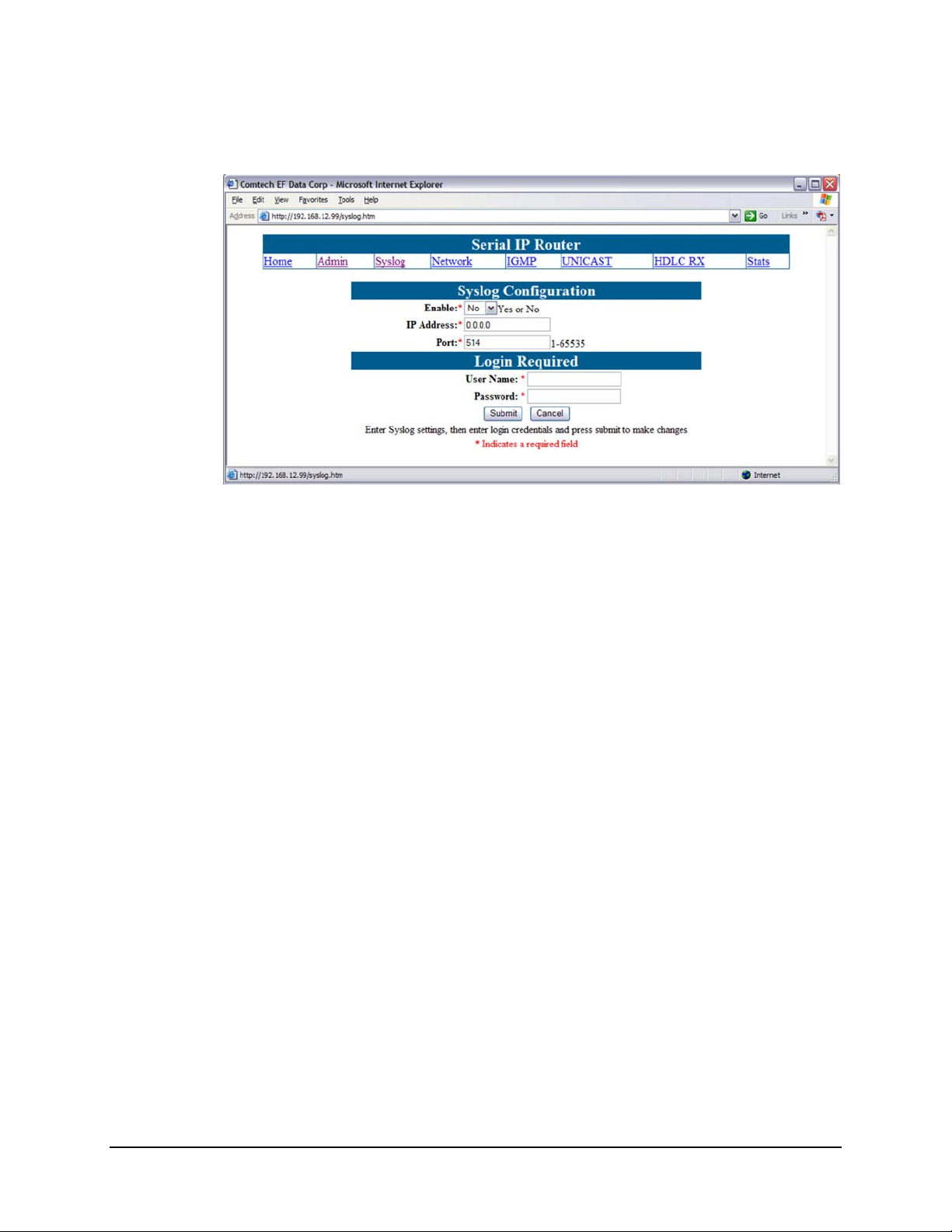
5.2.2 Syslog Configuration
Figure 5-4. Syslog Configuration page
Syslog is a common feature of the Linux operating system. Syslog allows the events that
occur on the MR-SIP to be sent to a server where they can be logged. The events are
delivered to a configured server over Ethernet IP.
Enable
Enables or disables the Syslog feature.
IP Address
The IP address of the Syslog server.
Port
The port of the Syslog server. The default port number is
514.
5-4
Page 51

Digicast Media Router Serial IP (SIP): CMR-5910 (MG-SIP) & CMR-5920 (MR-SIP) Revision A
Device Management via User Interfaces - CMR-5920 (MR-SIP) MN/MDRTRIPDC.IOM
5.2.3 Network Configuration
Figure 5-5. Network Configuration page
The Network Configuration page has the following configurable parameters:
IP Address
The IP Address assigned to the MR-SIP LAN interfaces. The IP Address is
entered in dotted decimal format.
Subnet Mask
The Subnet Mask assigned to the MR-SIP LAN interface. The Subnet Mask is
entered in dotted decimal format and is typically 255.0.0.0 for an A-Class mask,
255.255.0.0 for a B-Class mask, or 255.255.255.0 for a C-Class mask.
Default Gateway
The Default Gateway assigned to the MR-SIP LAN interface is the address of a
local router to which all non-local subnet traffic will be directed. The Default
Gateway is entered in dotted decimal format and must be with in the subnet of
the IP Address assigned to the LAN interface.
5-5
Page 52

Digicast Media Router Serial IP (SIP): CMR-5910 (MG-SIP) & CMR-5920 (MR-SIP) Revision A
Device Management via User Interfaces - CMR-5920 (MR-SIP) MN/MDRTRIPDC.IOM
5.2.4 IGMP Configuration
Figure 5-6. IGMP Configuration page
Internet Group Management Protocol (IGMP) is supported on the MR-SIP and prevents
unwanted Multicast traffic from being output to the LAN if no receivers are requesting
the service. Configuration of the IGMP features are as follows:
Enable
Enables or disables the IGMP feature on the MR-SIP.
Query period
Defines how often a query message is issued to the network. The query message
will solicit for Multicast clients.
Maximum tries
Defines the number of attempts made before the Multicast stream is pruned (shut
off) to the network.
Response timeout
In addition to the Query Period and the Maximum Tries, the Response Timeout
defines the amount of additional time the MR-SIP will wait for a response before
pruning (shutting off) a Multicast stream.
5-6
Page 53

Digicast Media Router Serial IP (SIP): CMR-5910 (MG-SIP) & CMR-5920 (MR-SIP) Revision A
Device Management via User Interfaces - CMR-5920 (MR-SIP) MN/MDRTRIPDC.IOM
5.2.5 Unicast Routing Configuration
Figure 5-7. Unicast Routing Configuration page
Provides configuration for the support of Unicast traffic.
Allow Unicast
Enables or disables support for Unicast traffic.
Route unknown to default gateway
If a Unicast address is received and not within the local subnet, the packets will
instead be forwarded to the configured default gateway instead of being
discarded.
5-7
Page 54

Digicast Media Router Serial IP (SIP): CMR-5910 (MG-SIP) & CMR-5920 (MR-SIP) Revision A
Device Management via User Interfaces - CMR-5920 (MR-SIP) MN/MDRTRIPDC.IOM
5.2.6 HDLC RX Configuration
Figure 5-8. HDLC RX Configuration page
Address
The HDLC address entered as four hexadecimal digits. The HDLC addresses
must be identical to what are configured for the route entries on the CMR-5910
Digicast Media Router Serial IP Gateway (MG-SIP).
5-8
Page 55

Digicast Media Router Serial IP (SIP): CMR-5910 (MG-SIP) & CMR-5920 (MR-SIP) Revision A
Device Management via User Interfaces - CMR-5920 (MR-SIP) MN/MDRTRIPDC.IOM
5.2.7 Statistics
Figure 5-9. HDLC Downlink Route Statistics page
The HDLC Downlink Route Statistics page displays the statistics for all configured
routes. Pressing
Page Up and Down on the keyboard allows the user to scroll up or down
through the configured routes on the MR-SIP.
Multicast / Unicast Received
The number of IP packets received on this route since the statistics were last
cleared.
Multicast / Unicast Dropped
The number of IP packets dropped on this route since the statistics were last
cleared.
Address
The address assigned to the associated route.
Min (Mbps)
The minimum bandwidth received on this route since the statistics were last
cleared.
Max (Mbps)
The maximum bandwidth received on this route since the statistics were last
cleared.
Average (Mbps)
The average bandwidth received on this route.
5-9
Page 56

Digicast Media Router Serial IP (SIP): CMR-5910 (MG-SIP) & CMR-5920 (MR-SIP) Revision A
A
Device Management via User Interfaces - CMR-5920 (MR-SIP) MN/MDRTRIPDC.IOM
5.3 Terminal Interface
The Terminal Interface provides the user with a textual configuration dialog for
configuring the MR-SIP. This method of configuration should be used for initial
configuration of the unit – i.e., configuring the network parameters for the unit, but not
for normal operation. The Web (HTTP) Interface is recommended for operational
management.
The Terminal Interface allows the entire unit to be configured and managed, but this
interface can only be used while a serial connection is present between the MR-SIP and a
PC. While the same menu information is displayed via the Telnet interface, there are
specific features available only via the ‘serial interface’ access method – these ‘serial
interface only’ features are noted in this section.
Figure 5-10 shows the hierarchal structure of the Terminal Interface-based menus, and
the sections in this chapter which provide figures of these submenu pages.
Main Menu
(5.3.1)
dministration
Menu (5.3.2)
HLDC Configuration
Menu (5.3.3)
IGMP Menu
(5.3.4)
Stats Menu
(5.3.5)
Network Menu
(5.3.6)
Unicast Routing
Menu (5.3.7)
(Downlink) HDLC
Address Config (5.3.3.1)
HDLC Downlink Stats
Menu (5.3.5.1)
Detailed Downlink Stats
Menu (5.3.5.1.1)
Ethernet Stats Menu
(5.3.5.2)
Figure 5-10. Menu Hierarchy (via Terminal Interface)
Once the terminal interface is connected, as described in Chapter 2.4 Initi al C onfigurat ion,
press the
<ENTER> key. Th e user sho uld observe the the Main Men u, shown in Figure 5-11.
5-10
Page 57

Digicast Media Router Serial IP (SIP): CMR-5910 (MG-SIP) & CMR-5920 (MR-SIP) Revision A
Device Management via User Interfaces - CMR-5920 (MR-SIP) MN/MDRTRIPDC.IOM
5.3.1 Main Menu
Figure 5-11. Main Menu
5.3.2 Administration Menu
Figure 5-12. Administration Menu
5-11
Page 58

Digicast Media Router Serial IP (SIP): CMR-5910 (MG-SIP) & CMR-5920 (MR-SIP) Revision A
Device Management via User Interfaces - CMR-5920 (MR-SIP) MN/MDRTRIPDC.IOM
5.3.3 HDLC Configuration Menu
Figure 5-13. HDLC Configuration Menu
5.3.3.1 (Downlink) HDLC Address Configuration Menu
Figure 5-14. (Downlink) HDLC Address Configuration Menu
5-12
Page 59

Digicast Media Router Serial IP (SIP): CMR-5910 (MG-SIP) & CMR-5920 (MR-SIP) Revision A
Device Management via User Interfaces - CMR-5920 (MR-SIP) MN/MDRTRIPDC.IOM
5.3.4 IGMP Configuration Menu
Figure 5-15. IGMP Configuration Menu
5.3.5 Stats (Statistics) Menu
Figure 5-16. Stats Menu
5-13
Page 60
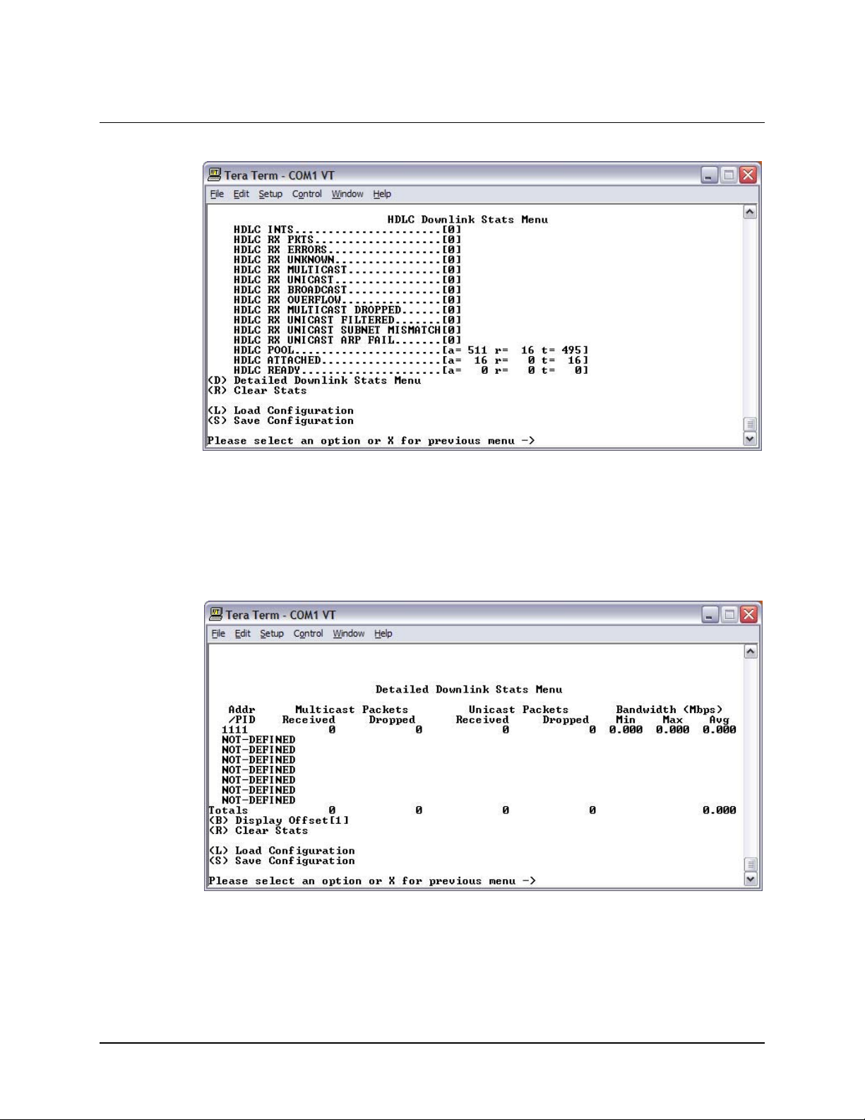
Digicast Media Router Serial IP (SIP): CMR-5910 (MG-SIP) & CMR-5920 (MR-SIP) Revision A
Device Management via User Interfaces - CMR-5920 (MR-SIP) MN/MDRTRIPDC.IOM
5.3.5.1 HDLC Downlink Stats Menu
Figure 5-17. HDLC Downlink Stats Menu
5.3.5.1.1 Detailed Downlink Stats Menu
Figure 5-18. Detailed Downlink Stats Menu
5-14
Page 61
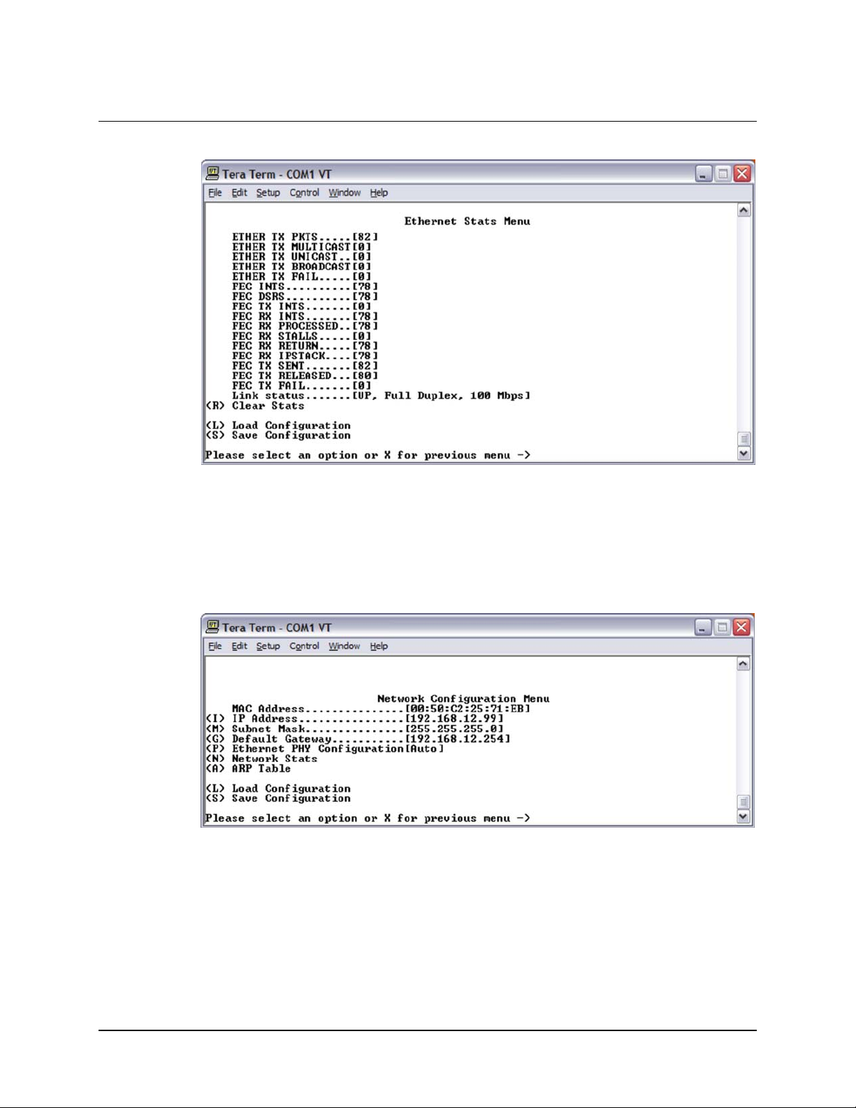
Digicast Media Router Serial IP (SIP): CMR-5910 (MG-SIP) & CMR-5920 (MR-SIP) Revision A
Device Management via User Interfaces - CMR-5920 (MR-SIP) MN/MDRTRIPDC.IOM
5.3.5.2 Ethernet Stats Menu
Figure 5-19. Ethernet Stats Menu
5.3.6 Network Configuration Menu
Figure 5-20. Network Configuration Menu
5-15
Page 62

Digicast Media Router Serial IP (SIP): CMR-5910 (MG-SIP) & CMR-5920 (MR-SIP) Revision A
Device Management via User Interfaces - CMR-5920 (MR-SIP) MN/MDRTRIPDC.IOM
5.3.7 Unicast Routing Configuration Menu
Figure 5-21. Unicast Routing Configuration Menu
5.4 Telnet Interface
Telnet provides a textual interface over a LAN. Most PCs have the capability to use
Telnet. To use Telnet on a Microsoft Windows
The dialog is shown in
where
xxx.xxx.xxx.xxx is the IP address of the MR-SIP. If the port number has been
modified from the Standard 23 via the Terminal Interface, then the port number must be
appended with a colon to the IP address.
The user will be prompted to enter the user name and password to gain access to the
telnet interface.
NOTE
The default username is comtech and the default password is
comtech, both of which are case sensitive.
®
product, click , then .
Figure 5-22. In the Open dialog, enter “telnet xxx.xxx.xxx.xxx”
Figure 5-22. Starting Telnet Session
Once the menu is started, press
displayed as shown in
5-16
Figure 5-23.
<ENTER> and the main menu of the MR-SIP be
Page 63

Digicast Media Router Serial IP (SIP): CMR-5910 (MG-SIP) & CMR-5920 (MR-SIP) Revision A
T
Device Management via User Interfaces - CMR-5920 (MR-SIP) MN/MDRTRIPDC.IOM
Figure 5-23. Main Menu via Telnet
The user may navigate the menus in the same manner as the Terminal Interface. With
specific exceptions as noted in the Terminal Interface section, the menus available via
Telnet and Serial interfaces are identical.
5.5 Trivial File Transfer Protocol (TFTP)
The MR-SIP support changes to the resident software and firmware by means of the
Trivial File Transfer Protocol (TFTP). This enables changes to be made remotely via the
LAN interface. It is recommended to use Solarwinds TFTP server application (available
at
http://support.solarwinds.net/updates/SelectProgramFree.cfm).
To modify the software and/or firmware, use the following procedures:
Configure the server as follows:
a)
File ! Configuration ! Select the ‘TFTP Root Directory’. Set up the location
of the MR-SIP files.
b)
File ! Configuration ! Select the ‘Security’ tab and make sure ‘Transmit and
Receive
c) Save configuration.
The server is now configured for the file transfer process.
IMPORTAN
’ are selected.
Because the MR-SIP stops processing data traffic during the
download process, it is recommended that this upgrade procedure be
performed during scheduled network down time.
Do NOT remove power from the unit during the download process.
5-17
Page 64

Digicast Media Router Serial IP (SIP): CMR-5910 (MG-SIP) & CMR-5920 (MR-SIP) Revision A
Device Management via User Interfaces - CMR-5920 (MR-SIP) MN/MDRTRIPDC.IOM
To modify code via Telnet:
Step Procedure
1 Start up Solarwinds TFTP server – Ensure configuration as described
previously.
2 Ensure that the code provided by CEFD is located in the TFTP Root
directory.
3 Start up Telnet client and initiate a session with the MR-SIP as
described in the Terminal Interface section.
4 Select ‘A’ for Administrative.
5 Select ‘D’ for Download.
6 Enter the IP address of the TFTP server and wait for the message
“Upgrade complete. Press any key to continue.”
This code modification process can also be conducted via the Web Interface, under the
Administrative page, or the Terminal Interface under the Main Menu.
IMPORTANT
Under heavy traffic conditions, the TFTP transfer may take several
minutes. The transfer process reported by Solarwinds may show
greater than 100% transferred, but this is a normal condition. Be
patient and allow the transfer to take place.
5.6 Simple Network Management Protocol (SNMP) (Future)
Simple Network Management Protocol (SNMP) has not been enabled on this product and
is planned as a future release. However, when enabled, SNMP allows an SNMP Manager
such as OpenView or Castle Rock to be used to remotely manage the MR-SIP in an
automated fashion.
The MR-SIP supports SNMP versions 1 and 2 (SNMPv1 and SNMPv2). SNMP version
3 (SNMPv3) will be supported in future releases. Two types of Management Information
Bases (MIBs) are supported: MIB II and private MIB.
MIB II is the default MIB that is used to gather generic information about the unit, such
as system ‘up’ time, packets sent or received on an interface, etc. MIB II is designed for
only read access, not write access. To read and write configuration parameters over
SNMP requires a private MIB. The private MIB allows parameter s to be set on the
Web, Terminal or Telnet interfaces.
The elements Object Identifiers (OIDs) of the MR-SIP’s MIB will be listed in the
appendix of a future revision of this manual. CEFD has been assigned an SNMP
designator by the IEEE, which will be found in all elements of the MR-SIP’s MIB.
NOTE
The assigned designator for CEFD (enterprise OID) is 1.3.6.4.1.18723.
5-18
Page 65

Digicast Media Router Serial IP (SIP): CMR-5910 (MG-SIP) & CMR-5920 (MR-SIP) Revision A
Device Management via User Interfaces - CMR-5920 (MR-SIP) MN/MDRTRIPDC.IOM
The MR-SIP support configurable community strings for added security. Note passwords
cannot be remotely queried over SNMP as a security precaution.
For SNMP access from a remote network via the public Internet, a VPN connection to the
MR-SIP will need to be established using third-party VPN client/server access.
Notes:
The default community string for the public elements is
community string is
private.
public and the private
5-19
Page 66

Digicast Media Router Serial IP (SIP): CMR-5910 (MG-SIP) & CMR-5920 (MR-SIP) Revision A
Device Management via User Interfaces - CMR-5920 (MR-SIP) MN/MDRTRIPDC.IOM
This page is deliberately left blank.
5-20
Page 67

A.1 Introduction
The MG-SIP and MR-SIP are enabled to receive an upgrade via Trivial File Transfer
Protocol (TFTP) transmission. It is recommended to use the Solarwinds TFTP server
application (available at
upgrading the device.
Once the TFTP server is enabled and the new file (
copied to the TFTP server, the following procedures may be used to upgrade the device.
NOTE
Appendix A. SOFTWARE
UPGRADE
http://support.solarwinds.net/updates/SelectProgramFree.cfm) for
The user will be instructed whether to select Application or FPGA
code in the download instructions provided by CEFD when new code is
provided.
Application or FPGA) has been
A–1
Page 68

Digicast MEdia Router Serial IP (SIP): CMR-5910 (MG-SIP) & CMR-5920 (MR-SIP) Revision A
Software Upgrade MN/MDRTRIPDC.IOM
A.2 Web Interface
Access the Administrative Configuration page (Figure A-1):
a) In the
b) Select
c) In the second
d) When the update is complete, the message “Press any key to continue”
e) When the unit has been upgraded, reset the unit by entering a valid username
Update Firmware section, enter the Unit TFTP Server IP Address.
Application or FPGA for the Image Type to be upgraded.
Login Required section, enter a valid username and password,
then select
IMPORTANT
will be displayed.
and password in the first
Update. The software update will begin to download.
Do NOT power the unit down during the upgrade process.
Login Required section and selecting Reset Unit.
Figure A-1. TFTP Download (via Web Interface – MG-SIP shown)
A–2
Page 69
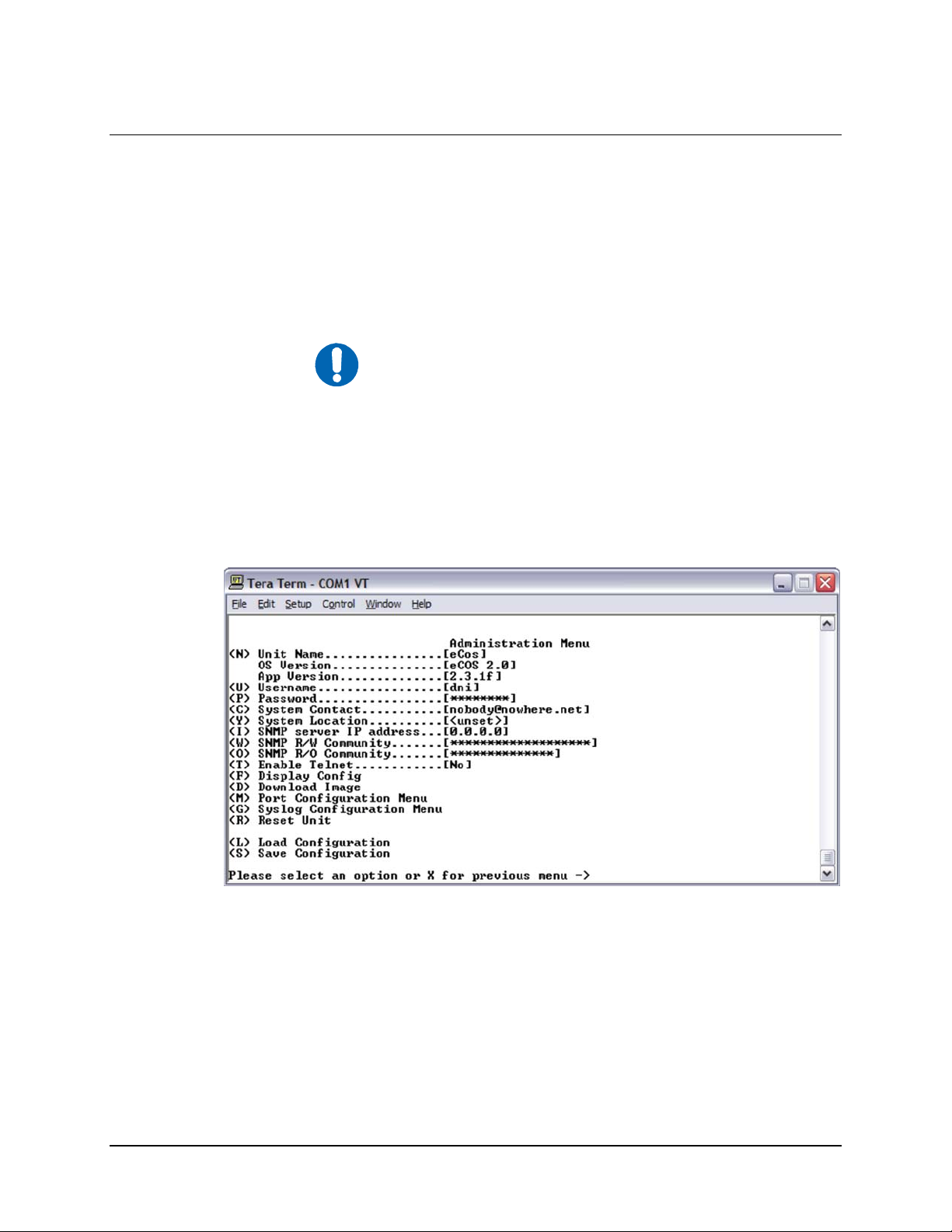
Digicast MEdia Router Serial IP (SIP): CMR-5910 (MG-SIP) & CMR-5920 (MR-SIP) Revision A
Software Upgrade MN/MDRTRIPDC.IOM
A.3 Telnet or Terminal Interface
Access the Administration Menu (Figure A-2):
a) Select
b) At the “Image type” prompt, enter
c) Enter the TFTP IP server address. Once the TFTP IP server address is
d) When the update is complete, the message “Press any key to continue”
e) When the unit has been upgraded, reset the unit by selecting
(D) for Download Image.
1 for Application or 2 for FPGA.
entered, the software update will begin to download.
Do NOT power the unit down during the upgrade process.
IMPORTANT
will be displayed (Figure A-3).
and ‘
Y’ to confirm the reset.
(R) for Reset
Figure A-2. Sample TFTP (via Terminal Interface – MG-SIP shown)
A–3
Page 70

Digicast MEdia Router Serial IP (SIP): CMR-5910 (MG-SIP) & CMR-5920 (MR-SIP) Revision A
Software Upgrade MN/MDRTRIPDC.IOM
Figure A-3. TFTP Download (via Telnet Interface)
Notes:
A–4
Page 71

Appendix B. IP ROUTING
B.1 Introduction
The MG-SIP provides state-of-the-art encapsulation based on the HDLC Specification
(ISO/IEC 13239). The MG-SIP provides the following configuration features:
• HDLC Encapsulation of IP datagrams
• Unicast Routing
• Multicast Routing
• 64 Configurable Routes
• Multicast Zones
B.2 Route Configuration
SUPPORT
Both Unicast and Multicast IP datagrams are encapsulated per the HDLC specification.
Routing of datagrams is accomplished by configuration of the MG Route Table,
described in the following section.
B.2.1 Unicast Routing
Unicast routing provides point-to-point delivery of IP datagrams. Routes for Unicast IP
packets are configured according to the following:
• IP Addresses, which fall into three classes, namely: Class A (0.0.0.0 to
127.255.255.255), Class B (128.0.0.0 to 191.255.255.255), and Class C (192.0.0.0
to 223.255.255.255).
• HDLC Addresses, to which a specific IP destination address is mapped. This
identifies the packets in the HDLC stream for a particular route. The MR-SIP
B-1
Page 72

Digicast Media Router Serial IP (SIP): CMR-5910 (MG-SIP) & CMR-5920 (MR-SIP) Revision A
IP Routing Support MN/MDRTRIPDC.IOM
uses the HDLC addresses to filter required IP datagrams. An MR-SIP may be
configured to filter up to 32 unique HDLC addresses.
Unicast is supported by the MG-SIP as it would be in any routed network. A route is
created and a subnet mask is assigned to the route.
The MG-SIP uses Classless Inter-Domain Routing (CIDR) notation in which a ‘slash’
followed by a decimal number is used to represent the number of bits for the mask;
e.g., /32 is 255.255.255.255 and /24 is 255.255.255.0.
As stated previously, part of the route configuration is a HDLC address which identifies
the IP route in the data stream.
B.2.2 Multicast Routing
Multicast routing provides point-to-multipoint delivery of IP datagrams. Routes for
multicast IP packets are configured according to the following:
• IP Addresses, which fall into class D (224.0.0.0 to 239.255.255.255)
• HDLC Addresses, to which a specific IP destination address is mapped. This
identifies the packets in the HDLC stream for a particular route. The MR-SIP
uses the HDLC addresses to filter required IP datagrams.
B.3 64 Routes
The MG-SIP and MR-SIP are capable of providing up to 64 unique IP routes. Each IP
route can be configured as Unicast or Multicast. Additional routes may be supported by
using the Multicast Zones feature described in the next section.
Routes can be assigned to HDLC addresses in the range 0000 to FFFF.
B.4 Multicast Zones
The Multicast Zones feature allows the user to more efficiently configure the Gateway
when supporting multicasting. Using the IP subnetting techniques of Unicast routing,
Multicast Zones allows a single IP address to be specified on a route and a subnet mask
assigned to the route.
The MG-SIP uses Classless Inter-Domain Routing (CIDR) notation in which a ‘slash’
followed by a decimal number is used to represent the number of bits for the mask, e.g.
/32 is 255.255.255.255 and /24 is 255.255.255.0. The subnet mask defines how many
multicast IP addresses are allowed to be mapped to a single route. Care must be taken
when using the multicast zone feature since IP traffic present within the multicast zone
will be routed over the network.
B-2
Page 73

Digicast Media Router Serial IP (SIP): CMR-5910 (MG-SIP) & CMR-5920 (MR-SIP) Revision A
IP Routing Support MN/MDRTRIPDC.IOM
An example of multicast zone is as follows:
Multicast Route = 239.0.10.1
Multicast Zone Mask = 255.255.255.252
Multicast groups mapped to the 239.0.10.1 route:
• 239.0.10.1
• 239.0.10.2
• 239.0.10.3
• 239.0.10.4
B.5 Quality of Service (QoS)
Each route defined can be configured to provide a determined bandwidth. Note all QoS
rates are for the HDLC transport stream and are based on HDLC payloads. Therefore, IP
data rates may be slightly less due to the protocol overhead of HDLC. The bandwidth
attributes that may be set are as follows:
• Minimum: The guaranteed amount of bandwidth the MG will provide for this
route. The total number of routes with guaranteed bandwidth must always be less
than the rate of the egress port.
• Maximum: The maximum amount of bandwidth a route will be allowed to have.
Once the traffic for this route exceeds this level, packets will be silently discarded
to ensure that the maximum is not exceeded
• No Setting: If neither the Guaranteed nor the Maximum values are set, the route
will be allowed to use as much bandwidth as possible and possibly attempt to
exceed the egress bandwidth, which will result in lost data. Conversely, there is
not guaranteed bandwidth for the route – another route may utilize all available
bandwidth.
B-3
Page 74

Digicast Media Router Serial IP (SIP): CMR-5910 (MG-SIP) & CMR-5920 (MR-SIP) Revision A
IP Routing Support MN/MDRTRIPDC.IOM
Notes:
B-4
Page 75

Appendix C. SYSTEM LOG
C.1 Introduction
The MG-SIP and MR-SIP support a feature known as system logging, more commonly
called Syslog.
This section illustrates how a system logger can be set up on a Linux or Unix system
allowing the device to report system events to a logger attached via an Ethernet
connection.
C.2 Enabling a System Logger
To enable system logging, add the following command string to the bottom of the
/etc/syslog.conf file on the Logging Server:
CONFIGURATION
1
,
# log the mux messages to here
*.=info /var/log/mux.log
Where:
*.=info tells the logger to send all messages it receives from the Mux to the Dir/file
1
Note that this is merely a sample configuration. CEFD does not support the setup of a syslog
server, since it is assumed that one is already configured and operational for use.
C–1
Page 76

Digicast Media Router Serial IP (SIP): CMR-5910 (MG-SIP) & CMR-5920 (MR-SIP) Revision A
System Log Configuration MN/MDRTRIPDC.IOM
Looking in the top of file /etc/init.d/syslog2, the following is usually displayed:
#!/bin/bash
#
# syslog Starts syslogd/klogd.
#
#
# chkconfig: 2345 12 88
# description: Syslog is the facility by which many daemons use to log \
# messages to various system log files. It is a good idea to always \
# run syslog.
# Source function library.
. /etc/init.d/functions
[ -f /sbin/syslogd ] || exit 0
[ -f /sbin/klogd ] || exit 0
# Source config
if [ -f /etc/sysconfig/syslog ] ; then
. /etc/sysconfig/syslog
else
SYSLOGD_OPTIONS=”-m 0”
KLOGD_OPTIONS=”-2”
fi
Of specific interest is the following line:
SYSLOGD_OPTIONS=”-m 0”
By adding a –r suffix, this allows the server to accept messages from remote machines.
The edited line should read as follows:
SYSLOGD_OPTIONS=”-m 0 –r”
Check the services file, normally at /etc/services, to ensure that PORT 514 is defined.
By default this should be enabled on most machines.
NOTE
After making the changes you must restart syslogd.
On most machines, entering “service syslog restart” should complete the configuration.
2
This file may be in a different location.
C–2
Page 77

Appendix D. TROUBLESHOOTING
This section covers suggestions to assist the user in troubleshooting the MG-SIP or MRSIP. If the suggestions in this section do not result in correct operation of the device,
please contact Comtech EF Data Customer Support for further assistance.
SYMPTOM: Device does not power up
When the device power is on, the blue
is not illuminated, ensure the power supply is plugged in and tightly connected to the
device.
SYMPTOM: Cannot communicate with the device using a terminal/PC
If the user cannot communicate with the device using a CEFD-supplied terminal
cable and a communications port on a desktop PC or notebook PC:
• Ensure the terminal cable is connected to the PC’s communications port and
the
TERM port on the device.
• The communication program (HyperTerminal or TeraTerminal) should be
configured as 38,400 BAUD rate, 8 Data bits and No Parity and 1 Stop bit –
commonly referred to as 38,400/8/N/1.
• Flow control should also be disabled.
SYMPTOM: Cannot get E-LINK LED to illuminate on the device
The most common mistake is using an “Ethernet Crossover Cable” instead of a
standard “patch cord” or “straight-through cable.” A crossover cable should only
be used if connecting the device directly to a PC. Otherwise, a patch cord to an
Ethernet concentrator (Hub) or switch should be used.
PWR LED should be illuminated. If this LED
D–1
Page 78

Digicast Media Router Serial IP (SIP): CMR-5910 (MG-SIP) & CMR-5920 (MR-SIP) Revision A
Troubleshooting MN/MDRTRIPDC.IOM
SYMPTOM: Cannot ping the device
If the
E-LINK LED is illuminated but the user cannot ping the device, the most
likely causes are incorrect settings for the IP address or subnet mask. Ensure the
device and the PC are set with unique IP addresses that are in the same subnet.
If the device and the PC are not in the same subnet, then both the device and PC
must have a valid “Default Gateway” defined so that non-local traffic will be
redirected to this device for routing the IP messages between the two devices.
SYMPTOM: Device will not synchronize with an IRD or Encoder
The device may be connected directly from an RS-422/RS-530 output port to an
RS-422/RS-530 input port on a modem. If the modem will not lock, the most
likely cause is the data rate on the device or modem are not set correctly.
SYMPTOM: Device reports dropped packets
The most likely cause of this problem is the incoming data on a route or all routes
exceeds the configured egress bandwidth.
To remedy the problem:
• Look at the route statistics for the device and identify the routes with
dropped packets.
• Lower the rate of the incoming data or increase the maximum bandwidth
assigned to the route if QoS is set.
SYMPTOM: Device has a RED Alarm displayed
The most likely cause of the
ALARM LED is the maximum bandwidth has been
exceeded. Please refer to the previous item to troubleshoot this problem.
D–2
Page 79

METRIC CONVERSIONS
Units of Length
Unit
1 centimeter — 0.3937 0.03281 0.01094
Centimeter
Inch
Foot Yard Mile
6.214 x 10
Meter Kilometer Millimeter
-6
0.01 — —
—
-5
0.254 — 25.4
-4
0.3048 — —
-4
0.9144 — —
-4
— — —
1.609 x 10³
1.609 —
1 inch 2.540 — 0.08333 0.2778
1 foot 30.480 12.0 — 0.3333
1 yard 91.44 36.0 3.0 —
1 meter 100.0 39.37 3.281 1.094
1 mile
1 mm — 0.03937 — — — — — —
1 kilometer — — — — 0.621 — — —
1.609 x 10
5
6.336 x 10⁴ 5.280 x 10³ 1.760 x 10³
1.578 x 10
1.893 x 10
5.679 x 10
6.214 x 10
Temperature Conversions
Unit
32° Fahrenheit
212° Fahrenheit
-459.6° Fahrenheit
° Fahrenheit ° Centigrade
—
—
—
0
(water freezes)
100
(water boils)
273.1
(absolute 0)
Formulas
C = (F - 32) * 0.555
F = (C * 1.8) + 32
Units of Weight
Unit Gram
Ounce
Avoirdupois
Ounce
Troy
Pound
Avoirdupois
Pound
Troy
Kilogram
1 gram — 0.03527 0.03215 0.002205 0.002679 0.001
1 oz. avoir. 28.35 — 0.9115 0.0625 0.07595 0.02835
1 oz. troy 31.10 1.097 — 0.06857 0.08333 0.03110
1 lb. avoir. 453.6 16.0 14.58 — 1.215 0.4536
1 lb. Troy 373.2 13.17 12.0 0.8229 — 0.3732
1 kilogram
1.0 x 10
3
35.27 32.15 2.205 2.679 —
Page 80

2114 WEST 7TH STREET TEMPE ARIZONA 85281 USA
480 • 333 • 2200 PHONE
480 • 333 • 2161
FAX
Page 81

METRIC CONVERSIONS
Units of Length
Unit
1 centimeter — 0.3937 0.03281 0.01094
Centimeter
Inch
Foot Yard Mile
6.214 x 10
Meter Kilometer Millimeter
-6
0.01 — —
—
-5
0.254 — 25.4
-4
0.3048 — —
-4
0.9144 — —
-4
— — —
1.609 x 10³
1.609 —
1 inch 2.540 — 0.08333 0.2778
1 foot 30.480 12.0 — 0.3333
1 yard 91.44 36.0 3.0 —
1 meter 100.0 39.37 3.281 1.094
1 mile
1 mm — 0.03937 — — — — — —
1 kilometer — — — — 0.621 — — —
1.609 x 10
5
6.336 x 10⁴ 5.280 x 10³ 1.760 x 10³
1.578 x 10
1.893 x 10
5.679 x 10
6.214 x 10
Temperature Conversions
Unit
32° Fahrenheit
212° Fahrenheit
-459.6° Fahrenheit
° Fahrenheit ° Centigrade
—
—
—
0
(water freezes)
100
(water boils)
273.1
(absolute 0)
Formulas
C = (F - 32) * 0.555
F = (C * 1.8) + 32
Units of Weight
Unit Gram
Ounce
Avoirdupois
Ounce
Troy
Pound
Avoirdupois
Pound
Troy
Kilogram
1 gram — 0.03527 0.03215 0.002205 0.002679 0.001
1 oz. avoir. 28.35 — 0.9115 0.0625 0.07595 0.02835
1 oz. troy 31.10 1.097 — 0.06857 0.08333 0.03110
1 lb. avoir. 453.6 16.0 14.58 — 1.215 0.4536
1 lb. Troy 373.2 13.17 12.0 0.8229 — 0.3732
1 kilogram
1.0 x 10
3
35.27 32.15 2.205 2.679 —
Page 82

2114 WEST 7TH STREET TEMPE ARIZONA 85281 USA
480 • 333 • 2200 PHONE
480 • 333 • 2161
FAX
 Loading...