

Page 1

CLO-10
Link Optimizer
Installation and Operation Manual
For Firmware Version 1.2.1 or higher
(see New in this Release - Section 1.7)
Part Number MN/CLO-10.IOM
Revision 1
IMPORTANT NOTE: The information contained in this document supersedes all previously published
information regarding this product. Product specifications are subject to change without prior notice.
Page 2

Page 3

Errata A
Comtech EF Data Documentation Update
Subject:
Date:
Original Manual :
Part Number/Rev:
Agile Document ID:
Changes to Appendix A. REDUNDANT SYSTEM OPERATION
June 26, 2008
MN/CLO-10.IOM
Rev 1
ER-MN-CL
O-10_EA1
Agile CO Number:
CO4012
Change Specifics:
This information will be incorporated into the next revision.
Update Figures A-8 and A-9 in Appendix A. REDUNDANT SYSTEM OPERATION per redlines attached
on following pages.
Action: Replace pages A-9 through A-12 in manual with pages A-9 through A-12 provided in this Errata
to facilitate update.
AGILE DOC ID ER-MN-CLO- 10_EA1 THIS DOCUMENT IS NOT SUBJECT TO REVISION/UPDATE! AGILE CO4012
1
Page 4
AGILE DOC ID ER-MN-CLO- 10_EA1 THIS DOCUMENT IS NOT SUBJECT TO REVISION/UPDATE! AGILE CO4012
2
Page 5
AGILE DOC ID ER-MN-CLO- 10_EA1 THIS DOCUMENT IS NOT SUBJECT TO REVISION/UPDATE! AGILE CO4012
3
Page 6

This page is intentionally blank.
AGILE DOC ID ER-MN-CLO- 10_EA1 THIS DOCUMENT IS NOT SUBJECT TO REVISION/UPDATE! AGILE CO4012
4
Page 7

CLO-10 Link Optimizer Revision 1
Redundant System Operation MN/CLO-10.IOM
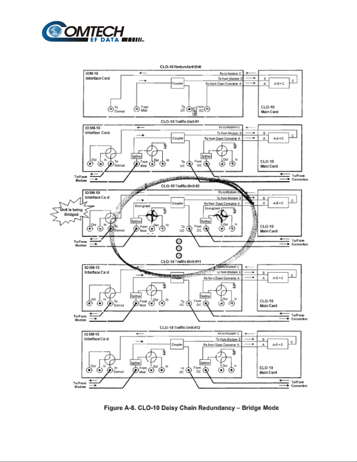
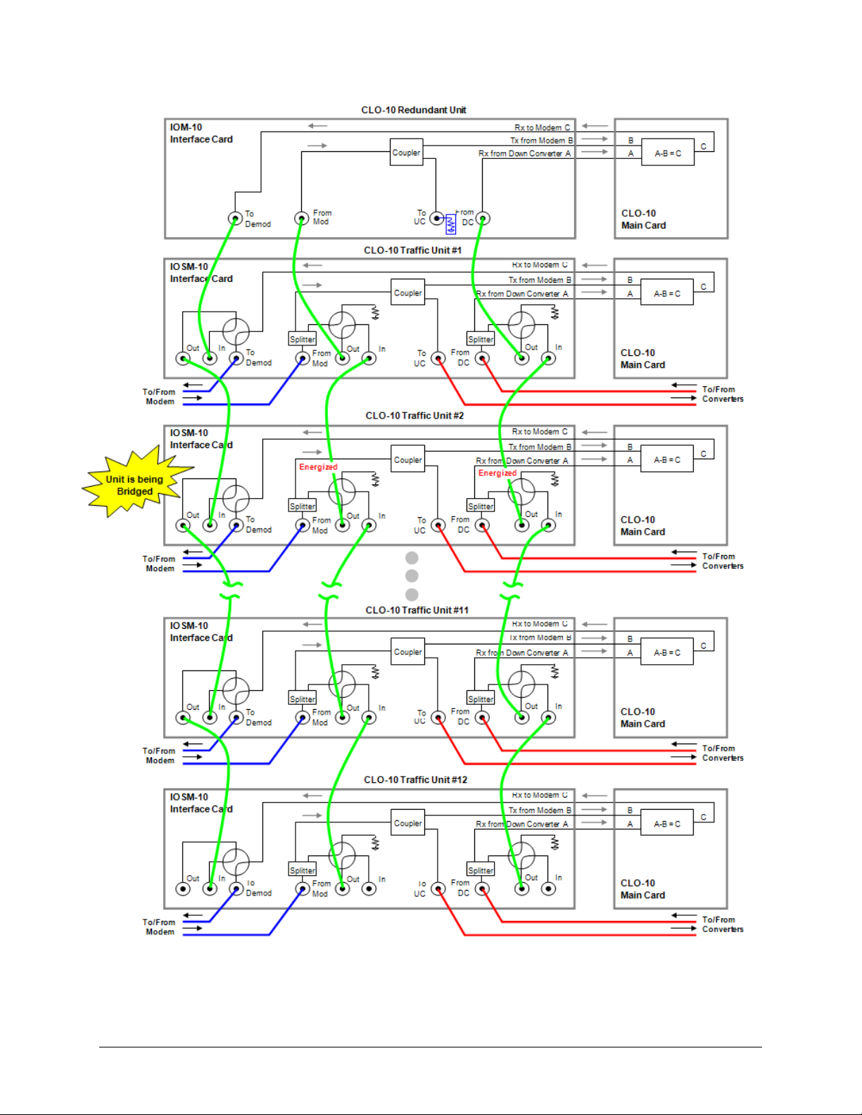
Figure A-8 shows the functional block diagram of Bridge Mode. In this example, Traffic Unit #2
is being bridged and, as the figure shows, the only energized “baseball” switches are on Traffic
Unit #2.
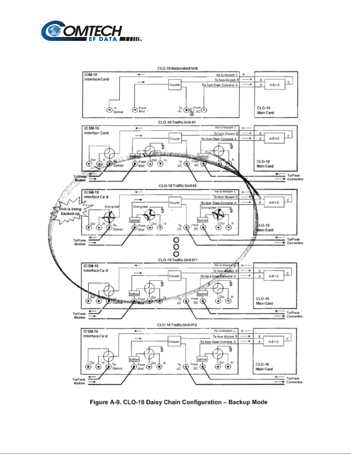
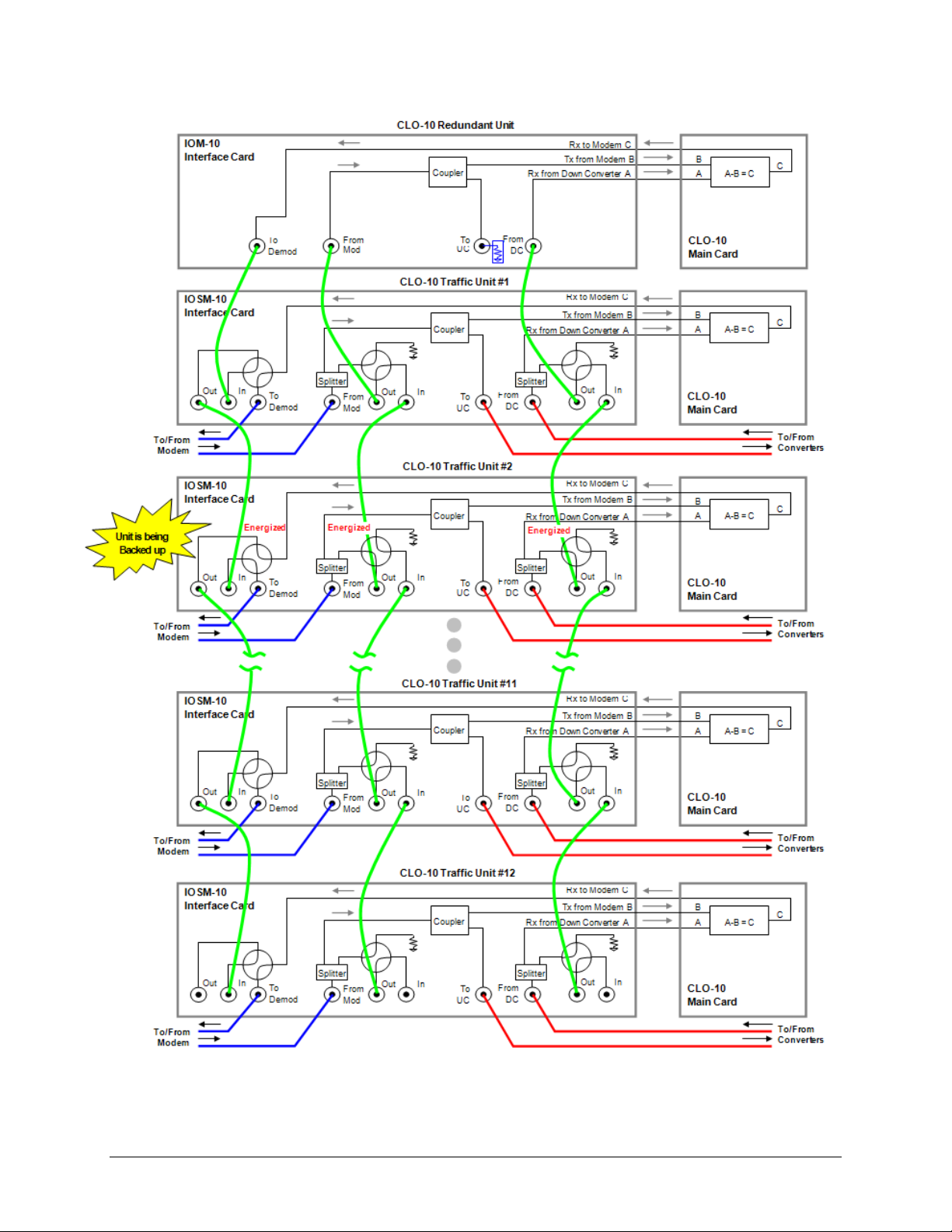
A.4.2 Backup Mode Operation
Backup Mode is similar to Bridge Mode, with an added function: In Backup Mode, the Redundant
Unit completely replaces the Traffic Unit. More specifically, the Redundant Unit will now be
online, and the failed Traffic Unit will go offline. The output IF signal directed to the demodulator
is subsequently taken from the Redundant Unit.
Figure A-9 shows the functional block diagram of Backup Mode. In this example, Traffic Unit #2
is being backed up and, as the figure shows, all of the “baseball” switches are energized on the
IOSM on Traffic Unit #2.
Backup Mode can be done manually or automatically. In automatic mode, the Redundant Unit
will monitor all of the Traffic Units continuously. When a fault is detected on any of these active
Traffic Units, the Redundant Unit will first bridge the faulted unit, then back it up. When a
faulted Traffic Unit needs to be replaced, its IOSM can be separated from the Traffic Unit
chassis, leaving the active online Redundant Unit HSB Daisy Chain intact through the IOSM
switch module. The chain can be extended without affecting the online unit’s operation.
A–9
Page 8
CLO-10 Link Optimizer Revision 1
Redundant System Operation MN/CLO-10.IOM
Figure A-8. CLO-10 Daisy Chain Redundancy – Bridge Mode
A–10
Page 9
CLO-10 Link Optimizer Revision 1
Redundant System Operation MN/CLO-10.IOM
Figure A-9. CLO-10 Daisy Chain Configuration – Backup Mode
A–11
Page 10

CLO-10 Link Optimizer Revision 1
Redundant System Operation MN/CLO-10.IOM
A.5 Cables and Connections
Once the CLO-10s and the accompanying equipment have been mounted, the user must properly
attach all required cabling. Referring to Figure A-10 and Figure A-11, interconnection between
all equipment in the Daisy Chain Redundancy System is accomplished as follows:
• Connect Redundancy and Traffic Unit(s) using the High Speed Bus Cable, fabricated and
supplied by CEFD. This cable connects to the DB-25F J2 Redundancy connector on each
unit, and consists of as few as (2X) DB-25M connectors (for the CEFD P/N
CA/RB0014-1-U2 1:1 Cable, shown in Figure A-10) to as many as (13X) connectors (for
the CEFD P/N CA/RB0014-12-U2 1:12 Cable, shown in Figure A-11). There will be only
as many DB-25M connectors as is required for the specific 1:N Redundancy system.
IMPORTANT
• Using CEFD-supplied BNC patch cable CA/BNC75OHM, first connect the inputs and
outputs between the Redundant Unit and Traffic Unit #1; then, connect the inputs and
outputs between each Traffic Unit subsequent in the redundancy chain.
The unit’s assignment number must match that of the numbered DB-25
connector on the High Speed Bus cable (CEFD P/N CA/RB0014-XX-U2).
• For the interfaces between the CLO-10, modem, and the up and down converters, use
standard off-the-shelf 75Ω BNC male-to-BNC male patch cables, supplied by the user.
As an alternative to using off-the-shelf patch cables, the user may purchase IF Cable
PL/0813-4 (75Ω BNC male-to-BNC male, 4’) from Comtech EF Data; this cable can be
ordered at the same time the order is placed for the CLO-10 Daisy Chain Redundancy
System.
A.5.1 75Ω Load in Redundant Unit
As shown in Figure A-10 and Figure A-11, a 75Ω load (CEFD P/N CN/CXLBNCTM01) must
be installed in the J5 (“To U/C”) port on the Redundant Unit’s IOM. This load is needed to
terminate the splitter on the IOM.
A–12
Page 11

CLO-10
Link Optimizer
Installation and Operation Manual
For Firmware Version 1.2.1 or higher
(see New in this Release - Section 1.7)
Part Number MN/CLO-10.IOM
Revision 1
June 18, 2008
Copyright © 2008 Comtech EF Data. All rights reserved. Printed in the USA.
Comtech EF Data, 2114 West 7th Street, Tempe, Arizona 85281 USA, 480.333.2200, FAX: 480.333.2161
Page 12

This page is intentionally blank.
Page 13

CLO-10 Link Optimizer Revision 1
Table of Contents MN/CLO-10.IOM
Table of Contents
TABLE OF CONTENTS ................................................................................................. III
TABLES ....................................................................................................................... VIII
FIGURES ....................................................................................................................... IX
PREFACE ...................................................................................................................... XI
Customer Support ........................................................................................................................ xi
About this Manual ...................................................................................................................... xii
Reporting Comments or Suggestions Concerning this Manual ................................................ xii
Conventions and References ...................................................................................................... xii
Cautions and Warnings ............................................................................................................. xii
Metric Conversion .................................................................................................................... xii
Recommended Standard Designations ..................................................................................... xii
Trademarks .............................................................................................................................. xiii
Electromagnetic Compatibility (EMC) Compliance .............................................................. xiii
EN55022 - 1997 Compliance ................................................................................................... xiii
EN50082-1 Compliance ........................................................................................................... xiii
Federal Communications Commission (FCC) ......................................................................... xiii
Safety Compliance ..................................................................................................................... xiv
EN 60950 ................................................................................................................................. xiv
Low Voltage Directive (LVD) ................................................................................................. xiv
Warranty Policy .......................................................................................................................... xv
Limitations of Warranty ............................................................................................................ xv
Exclusive Remedies ................................................................................................................. xvi
CHAPTER 1. INTRODUCTION ................................................................................ 1–1
1.1 Overview ........................................................................................................................ 1–1
1.2 Features .......................................................................................................................... 1–2
1.2.1 DoubleTalk™ Carrier-in-Carrier® .............................................................................. 1–2
1.2.2 Software – Flash Upgrading ....................................................................................... 1–2
1.2.3 Verification ................................................................................................................. 1–2
1.2.4 Remote Control ........................................................................................................... 1–3
iii
Page 14

CLO-10 Link Optimizer Revision 1
Table of Contents MN/CLO-10.IOM
1.3 Description of CLO-10 Features.................................................................................. 1–3
1.3.1 Front Panel .................................................................................................................. 1–3
1.3.2 Rear Panel ................................................................................................................... 1–3
1.4 Major Assemblies .......................................................................................................... 1–3
1.5 FAST Options and Hardware Options ....................................................................... 1–4
1.5.1 FAST System .............................................................................................................. 1–4
1.5.1.1 FAST Options ..................................................................................................... 1–4
1.5.1.2 FAST Implementation ........................................................................................ 1–4
1.5.2 Hardware Options ....................................................................................................... 1–5
1.6 Functional Description ................................................................................................. 1–5
1.6.1 What is DoubleTalk™Carrier-in-Carrier®? ................................................................ 1–5
1.6.2 Application Requirements .......................................................................................... 1–7
1.6.3 System Functionality .................................................................................................. 1–8
1.7 New in this Release........................................................................................................ 1–9
1.8 Summary of Specifications ......................................................................................... 1–10
1.8.1 System Specifications ............................................................................................... 1–10
1.8.2 Environmental and Physical Specifications .............................................................. 1–11
1.9 Dimensional Envelope ................................................................................................ 1–12
CHAPTER 2. INSTALLATION ................................................................................. 2–1
2.1 Unpacking and Inspection ............................................................................................ 2–1
2.2 Mounting ........................................................................................................................ 2–2
2.2.1 Optional Rear-Mounting Support Brackets ................................................................ 2–2
CHAPTER 3. REAR PANEL CONNECTORS ......................................................... 3–1
3.1 Connector Overview ..................................................................................................... 3–1
3.2 External Reference Connector, J1 (BNC-F) ............................................................... 3–2
3.3 Alarms Connector, P1A (DB-9F)................................................................................. 3–2
3.4 Remote Control Interface Connector, P1B (DB-9M) ................................................ 3–2
3.5 M&C 10/100 BaseT Ethernet Management Port (RJ-45) ......................................... 3–3
3.6 IOM/IOSM Connectors (BNC-F) ................................................................................ 3–4
3.7 IEC Line Input (AC Power) Connector ...................................................................... 3–5
iv
Page 15

CLO-10 Link Optimizer Revision 1
Table of Contents MN/CLO-10.IOM
3.8 DC Power Connector .................................................................................................... 3–5
3.9 Ground Connector ........................................................................................................ 3–6
CHAPTER 4. CABLES AND CONNECTIONS ........................................................ 4–1
4.1 Overview ........................................................................................................................ 4–1
4.2 External Cable Connections......................................................................................... 4–1
4.3 Redundancy Cable Connections .................................................................................. 4–1
CHAPTER 5. MODEM AND OPTIMIZER CONFIGURATION ................................. 5–1
5.1 Modem Configuration .................................................................................................. 5–1
5.1.1 Verify Link without Carrier-in-Carrier® .................................................................... 5–1
5.2 CLO-10 Configuration ................................................................................................. 5–1
5.2.1 CLO-10 Power ............................................................................................................ 5–1
5.2.2 Flash Updating ............................................................................................................ 5–2
5.2.2.1 Flash Update Help............................................................................................... 5–2
5.2.3 CLO-10 FTP Upload Procedure ................................................................................. 5–3
5.2.4 CLO-10 Tuning ........................................................................................................... 5–5
5.2.4.1 Initial Link Access Procedures ........................................................................... 5–5
5.2.4.2 Link Access Setup............................................................................................... 5–6
5.3 Other Useful Information............................................................................................. 5–6
CHAPTER 6. FRONT PANEL OPERATION ........................................................... 6–1
6.1 Introduction ................................................................................................................... 6–1
6.1.1 LED Indicators ............................................................................................................ 6–2
6.1.2 Keypad ........................................................................................................................ 6–3
6.1.3 Vacuum Fluorescent Display (VFD) .......................................................................... 6–4
6.2 CLO-10 Menu Structure .............................................................................................. 6–5
6.3 Main (Top-level Select) Menu ...................................................................................... 6–6
6.4 CONFIG (Configuration) ............................................................................................. 6–7
6.4.1 CONFIG: Remote ....................................................................................................... 6–8
CONFIG: Remote Æ Serial ........................................................................................ 6–8
CONFIG: Remote Æ Serial Æ Interface .................................................................... 6–8
CONFIG: Remote Æ Serial Æ Interface Æ RS485-2W or RS485-4W .................... 6–8
CONFIG: Remote Æ Serial Æ Baudrate ................................................................... 6–9
CONFIG: Remote Æ Ethernet .................................................................................... 6–9
v
Page 16

CLO-10 Link Optimizer Revision 1
Table of Contents MN/CLO-10.IOM
CONFIG: Remote Æ Ethernet Æ Gateway ............................................................... 6–9
CONFIG: Remote Æ Ethernet Æ Address ................................................................. 6–9
CONFIG: Remote Æ Ethernet Æ MAC ..................................................................... 6–9
6.4.2 CONFIG: BW (Bandwidth) ...................................................................................... 6–10
6.4.3 CONFIG: Uplink (Uplink Frequency) ...................................................................... 6–10
6.4.4 CONFIG: Downlink (Downlink Frequency) ............................................................ 6–10
6.4.5 CONFIG: Remod (Remodulation Parameters) ......................................................... 6–11
CONFIG: Remod ÆFrequency ................................................................................ 6–11
CONFIG: Remod Æ On/Off .................................................................................... 6–11
CONFIG: Remod Æ Attenuation ............................................................................. 6–11
6.4.6 CONFIG: CnC (Carrier-in-Carrier© Parameters) ..................................................... 6–12
CONFIG: CnC Æ SearchDelay ................................................................................ 6–12
CONFIG: CnC Æ FrequencyOffset ......................................................................... 6–12
6.4.7 CONFIG: Misc: (Miscellaneous Configurations) ..................................................... 6–12
CONFIG: Misc: Æ Mask .......................................................................................... 6–12
CONFIG: Misc: Æ Alarm Mask: Æ Unit ................................................................ 6–13
CONFIG: Misc: Æ Alarm Mask: Æ Unit Alarm Mask: Æ ERC ............................ 6–13
CONFIG: Misc: Æ Alarm Mask: Æ Unit Alarm Mask: Æ ACQ_FAIL ................. 6–13
CONFIG: Misc: Æ Alarm Mask: Æ Uplink ............................................................ 6–13
CONFIG: Misc: Æ Alarm Mask: Æ Downlink ....................................................... 6–13
CONFIG: Misc: Æ Reference (Reference Oscillator) .............................................. 6–14
CONFIG: Misc: Æ Redundancy .............................................................................. 6–14
6.5 Monitor ........................................................................................................................ 6–15
6.5.1 Monitor: Alarms (Live Alarms) ................................................................................ 6–15
Monitor: Alarms Æ (Live Alarms:) Unit (Unit Alarms) .......................................... 6–15
Monitor: Alarms Æ (Live Alarms:) Uplink (Uplink Alarms) .................................. 6–16
Monitor: Alarms Æ( Live Alarms:) Downlink (Downlink Alarms) ........................ 6–16
Monitor: Alarms Æ( Live Alarms:) Remod (Remod Alarms) ................................. 6–17
6.5.2 Monitor: Event Log (Stored Events) ......................................................................... 6–17
6.5.3 Monitor: CnC (Carrier-in-Carrier®) .......................................................................... 6–18
6.5.4 Monitor: Temp .......................................................................................................... 6–18
6.5.5 Monitor: RSL (Receive Signal Level) ...................................................................... 6–18
6.6 TEST ............................................................................................................................ 6–19
6.7 INFO (Information) .................................................................................................... 6–20
INFO: Remote (Remote Control Information) ......................................................... 6–20
INFO: Bw (Bandwidth Information) ........................................................................ 6–20
INFO: Uplink (Uplink Information) ......................................................................... 6–20
INFO: Downlink (Downlink Information) ............................................................... 6–21
INFO: Remod (Remodulation Information) ............................................................. 6–21
INFO: CnC (Carrier-in-Carrier® Information) ......................................................... 6–21
INFO: Ref (Frequency Reference) ............................................................................ 6–21
vi
Page 17

CLO-10 Link Optimizer Revision 1
Table of Contents MN/CLO-10.IOM
6.8 SAVE/LOAD ............................................................................................................... 6–22
Save/Load: Save (Save Configuration) ..................................................................... 6–22
Save/Load: Load (Load Configuration) .................................................................... 6–23
6.9 UTILITY ...................................................................................................................... 6–24
Utility: Clock (Real-time Clock) .............................................................................. 6–24
Utility: Ref (Reference Adjustment) ......................................................................... 6–24
Utility: ID (Circuit Identification) ............................................................................ 6–25
Utility: Display (Display Brightness) ....................................................................... 6–25
Utility: Firmware ...................................................................................................... 6–25
Utility: FAST (FAST Code Options) ........................................................................ 6–27
APPENDIX A. REDUNDANT SYSTEM OPERATION ............................................ A–1
A.1 Introduction .................................................................................................................. A–1
A.1.1 Overview ................................................................................................................ A–1
A.1.2 Redundancy System Operational Rules ................................................................. A–3
A.2 Installation .................................................................................................................... A–4
A.3 Description of Modules ................................................................................................ A–5
A.3.1.1 Overview: CLO-10 with Input/Output Module (IOM) ...................................... A–5
A.3.1.2 Overview: CLO-10 With Input/Output Switch Module (IOSM) ...................... A–6
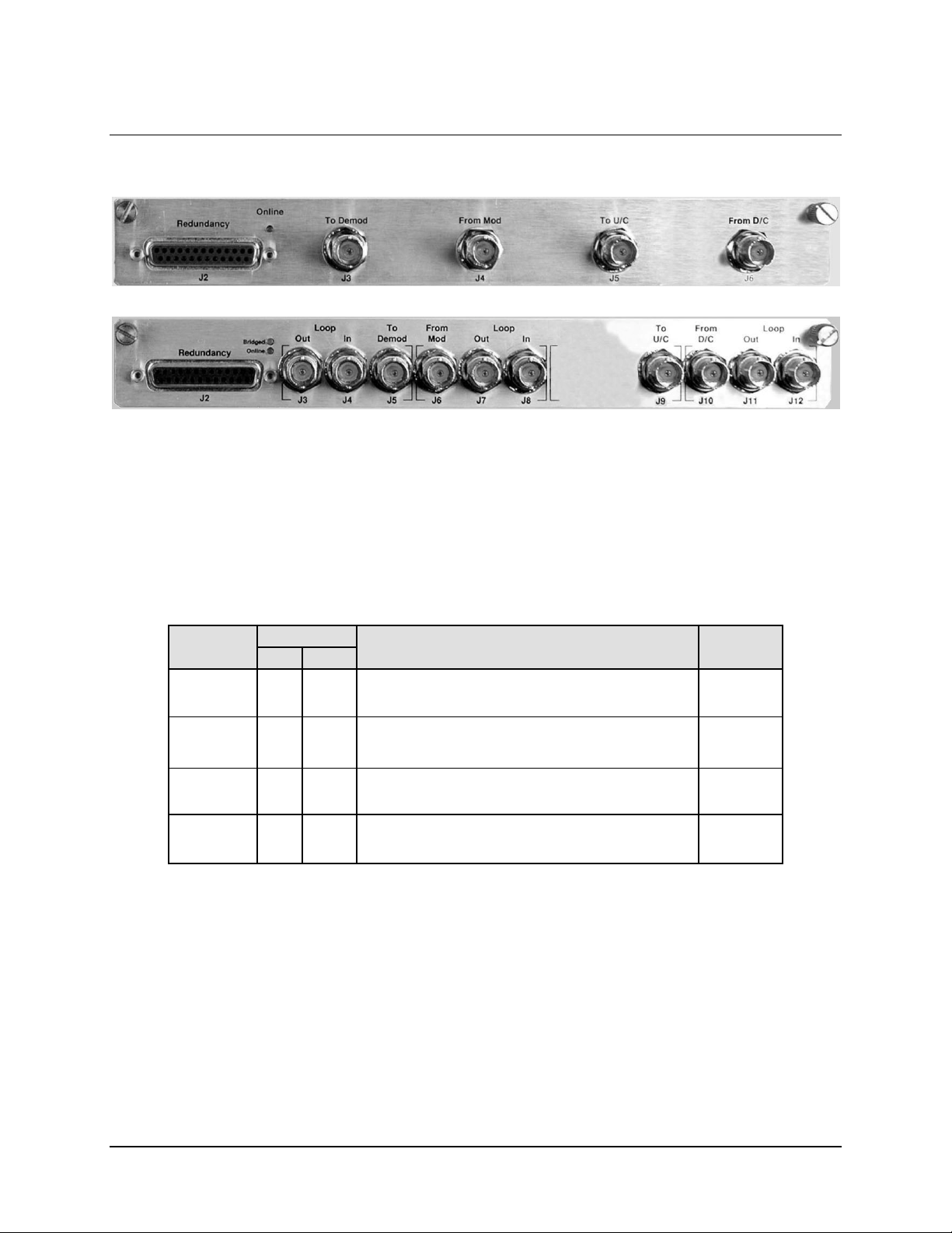
A.3.2 Connector Pinouts .................................................................................................. A–6
A.3.2.1 IOM / IOSM Redundancy Connector, J2 (DB-25F) .......................................... A–6
A.3.2.2 IOM / IOSM BNC Connectors .......................................................................... A–7
A.4 Description of Operation ............................................................................................. A–8
A.4.1 Bridge Mode Operation ......................................................................................... A–8
A.4.2 Backup Mode Operation ........................................................................................ A–9
A.5 Cables and Connections ............................................................................................ A–12
A.5.1 75Ω Load in Redundant Unit ............................................................................... A–12
A.5.2 1:1 Redundancy Configuration Cabling .............................................................. A–13
A.5.3 1:N Redundancy Configuration Cabling ............................................................. A–14
A.5.4 Adding and Removing CLO-10s and/or Modules ............................................... A–15
A.6 Front Panel Operation ............................................................................................... A–17
A.6.1 Redundancy Menu Access ................................................................................... A–17
A.6.2 Traffic Unit Redundancy Configuration .............................................................. A–18
A.6.3 Redundant Unit Redundancy Configuration ........................................................ A–18
A.6.3.1 Redundancy Enable /Disable ........................................................................... A–19
A.6.3.2 Redundancy Holdoffs ...................................................................................... A–19
A.6.3.3 Active Unit Selection ....................................................................................... A–19
A.6.3.4 Establish the Operating Mode .......................................................................... A–20
A.6.3.4.1 Switch Auto Off/On .................................................................................. A–20
A.6.3.4.2 Redundancy Unit – Manual Select ............................................................ A–20
vii
Page 18

CLO-10 Link Optimizer Revision 1
Table of Contents MN/CLO-10.IOM
A.6.3.5 Set the Redundant Unit Address via the Main Menu ...................................... A–22
A.6.4 Set Operation Mode ............................................................................................. A–24
A.6.4.1.1 Set Holdoff Period ..................................................................................... A–24
A.6.4.1.2 Set Backup Holdoff Period ........................................................................ A–24
A.6.4.1.3 Set Restore Holdoff Period ........................................................................ A–25
A.7 Daisy Chain Remote Addressing .............................................................................. A–26
A.7.1 Introduction to Addressing .................................................................................. A–26
A.7.2 Switching Addresses ............................................................................................ A–26
A.7.3 Traffic Unit Addresses ......................................................................................... A–26
APPENDIX B. REMOTE CONTROL ........................................................................ B-1
B.1 Overview ........................................................................................................................ B-1
B.2 RS-485 ............................................................................................................................ B-1
B.3 RS-232 ............................................................................................................................ B-2
B.4 Basic Protocol ................................................................................................................ B-2
B.5 Packet Structure ............................................................................................................ B-2
B.5.1 Start of Packet ......................................................................................................... B-3
B.5.2 Address ................................................................................................................... B-3
B.5.3 Instruction Code ...................................................................................................... B-3
B.5.4 Instruction Code Qualifier ...................................................................................... B-4
B.5.5 Message Arguments ................................................................................................ B-5
B.5.6 End Of Packet ......................................................................................................... B-5
B.6 Remote Commands and Queries ................................................................................. B-6
B.6.1 Switch Remote Commands and Queries for the CLO-10 Link Optimizer ............. B-7
B.6.2 Remote Commands and Queries For the CLO-10 Link Optimizer ........................ B-9
B.6.3 Commands and Queries ........................................................................................ B-15
B.6.4 Bulk Commands and Queries ............................................................................... B-19
Tables
Table 3-1. External Connections ................................................................................................ 3–1
Table 3-2. Alarm Interface Connector Pin Assignments ............................................................ 3–2
Table 3-3. Remote Control Interface Connector Pin Assignments ............................................. 3–2
Table 3-4. M&C Interface Connector Pin Assignments ............................................................. 3–3
Table 3-5. CLO-10 IOM BNC Connectors Reference ............................................................... 3–4
Table A-1. IOM (CEFD P/N PL/12833-1) BNC Connectors Reference ................................... A–7
Table A-2. IOSM (CEFD P/N PL/12834-1) BNC Connectors Reference ................................ A–7
viii
Page 19

CLO-10 Link Optimizer Revision 1
Table of Contents MN/CLO-10.IOM
Figures
Figure 1-1. CLO-10 Link Optimizer ........................................................................................... 1–1
Figure 1-2. CLO-10 Front Panel ................................................................................................. 1–3
Figure 1-3. CLO-10 Rear Panel (CLO-10-1 shown) .................................................................. 1–3
Figure 1-4. Conventional FDMA Link ....................................................................................... 1–6
Figure 1-5. Link with Carrier-in-Carrier® ................................................................................... 1–6
Figure 1-6. Conceptual Block Diagram ...................................................................................... 1–8
Figure 1-7. CLO-10 Dimensional Envelope ............................................................................. 1–12
Figure 2-1. Typical CLO-10 Rack Installation (Side View) ....................................................... 2–3
Figure 2-2. Installation of the Optional Rear-Mounting Support Brackets ................................ 2–4
Figure 3-1. CLO-10 Rear Panel (CLO-10-1 Shown).................................................................. 3–1
Figure 4-1. CLO-10 External Cable Connections – Standalone Configuration ......................... 4–2
Figure 5-1. Flash Update via Internet ......................................................................................... 5–2
Figure 6-1. CLO-10 Front Panel ................................................................................................. 6–1
Figure 6-2. CLO-10 Menu Tree .................................................................................................. 6–5
Figure A-1. CLO-10 1:1 Daisy Chain Redundancy ................................................................... A–2
Figure A-2. CLO-10 1:N Daisy Chain Redundancy (1:12 shown) ........................................... A–2
Figure A-3. Typical Rack-mounted Redundancy Configuration ............................................... A–4
Figure A-4. IOM (CEFD P/N PL/12833-1) ............................................................................... A–5
Figure A-5. CLO-10 With IOM – Block Diagram .................................................................... A–5
Figure A-6. IOSM (CEFD P/N PL/12834-1) ............................................................................. A–6
Figure A-7. CLO-10 With IOSM – Block Diagram .................................................................. A–6
Figure A-8. CLO-10 Daisy Chain Redundancy – Bridge Mode ............................................. A–10
Figure A-9. CLO-10 Daisy Chain Configuration – Backup Mode .......................................... A–11
Figure A-10. CLO-10 1:1 Daisy Chain Redundancy Cabling ................................................. A–13
Figure A-11. CLO-10 1:N Daisy Chain Redundancy Cabling (1:12 shown) .......................... A–14
Figure A-15. Module Removal/Installation ............................................................................. A–15
Figure A-16. Operating Configuration .................................................................................... A–16
Figure A-12. Redundancy Menu Tree ..................................................................................... A–17
Figure A-13. Unit Bridging in AUTO-OFF (manual operating) Mode .................................. A–21
Figure A-14. Unit Backup in AUTO-ON (automatic operating) Mode .................................. A–21
Figure A-17. CLO-10 Daisy Chain Addressing Scheme Example: User Remote M&C RS-232 .... A–27
Figure A-18. CLO-10 Daisy Chain Addressing Scheme Example: User Remote M&C RS-485 .... A–27
Figure A-19. CLO-10 Base Addressing Scheme Example for Daisy Chained Multiple Redundant
Systems: User Remote M&C RS-485.............................................................................. A–28
ix
Page 20

CLO-10 Link Optimizer Revision 1
Table of Contents MN/CLO-10.IOM
This page is intentionally blank.
x
Page 21

Customer Support
Contact the Comtech EF Data Customer Support Department for:
• Product support or training
• Reporting comments or suggestions concerning manuals
• Information on upgrading or returning a product
A Customer Support representative may be reached at:
Comtech EF Data
Attention: Customer Support Department
2114 West 7th Street
Tempe, Arizona 85281 USA
480.333.2200 (Main Comtech EF Data Number)
480.333.4357 (Customer Support Desk)
480.333.2161 FAX
Preface
To return a Comtech EF Data product (in-warranty and out-of-warranty) for repair or
replacement:
• Contact the Comtech EF Data Customer Support Department. Be prepared to supply the
Customer Support representative with the model number, serial number, and a description
of the problem.
• Request a Return Material Authorization (RMA) number from the Comtech EF Data
Customer Support representative.
• Pack the product in its original shipping carton/packaging to ensure that the product is not
damaged during shipping.
• Ship the product back to Comtech EF Data. (Shipping charges should be prepaid.)
For Online Customer Support
An RMA number request can be requested electronically by contacting the Customer Support
Department through the online support page at www.comtechefdata.com/support.asp
• Click “Return Material Authorization Instructions” from the Service page for detailed
information on our return procedures.
• Click the “RMA Request form” hyperlink, then fill out the form completely before
sending.
• Send e-mail to the Customer Support Department at service@comtechefdata.com.
For information regarding this product’s warranty policy, refer to the Warranty Policy, p. xv.
:
:
xi
Page 22

CLO-10 Link Optimizer Revision 1
Preface MN/CLO-10.IOM
About this Manual
This manual provides installation and operation information for the Comtech EF Data CLO-10
Link Optimizer. This is a technical document intended for earth station engineers, technicians,
and operators responsible for the operation and maintenance of the CLO-10.
Comtech EF Data reserves the right to change specifications of products described in this
document at any time without notice and without obligation to notify any person of such changes.
Information in this document may differ from information published in other Comtech EF Data
documents. Refer to the company website or contact Customer Service for the latest released
product information.
Reporting Comments or Suggestions Concerning this Manual
Comments and suggestions regarding the content and design of this manual are appreciated. To
submit comments, please contact the Comtech EF Data Technical Publications department:
TechnicalPublications@comtechefdata.com
Conventions and References
Cautions and Warnings
IMPORTANT
CAUTION
WARNING
IMPORTANT or NOTE indicates a statement that is associated with the task
being performed or information critical for proper equipment function.
CAUTION indicates a hazardous situation that, if not avoided, may result in
minor or moderate injury. CAUTION may also be used to indicate other
unsafe practices or risks of property damage.
WARNING indicates a potentially hazardous situation that, if not avoided,
could result in death or serious injury.
Metric Conversion
Metric conversion information is located on the inside back cover of this manual. This information
is provided to assist the operator in cross-referencing non-Metric to Metric conversions.
Recommended Standard Designations
Recommended Standard (RS) Designations are interchangeable with the designation of the
Electronic Industries Association (EIA).
xii
Page 23

CLO-10 Link Optimizer Revision 1
Preface MN/CLO-10.IOM
Trademarks
Product names mentioned in this manual may be trademarks or registered trademarks of their
respective companies and are hereby acknowledged.
Electromagnetic Compatibility (EMC) Compliance
This is a Class A product. In a domestic environment, it may cause radio interference that
requires the user to take adequate protection measures.
EN55022 - 1997 Compliance
This equipment meets the radio disturbance characteristic specifications for information
technology equipment as defined in EN55022.
EN50082-1 Compliance
This equipment meets the electromagnetic compatibility/generic immunity standard as defined in
EN50082-1.
Federal Communications Commission (FCC)
This equipment has been tested and found to comply with the limits for a Class A digital device,
pursuant to Part 15 of the FCC rules. These limits are designed to provide reasonable protection
against harmful interference when the equipment is operated in a commercial environment.
This equipment generates, uses, and can radiate ra dio freque ncy e nergy. If not installed and used in
accordance with the instruction manual, it may cause harmful interference to radio communications.
Operation of this equipment i n a residentia l area is likely to cause ha rmful interfere nce; in whic h case,
users are required to correct the interference at the ir own expe nse.
To ensure compliance, properly shielded cables for DATA I/O shall be used.
More specifically, these cables shall be shielded from end to end, ensuring a
continuous shield.
NOTE
xiii
Page 24

CLO-10 Link Optimizer Revision 1
Preface MN/CLO-10.IOM
Safety Compliance
EN 60950
Applicable testing is routinely performed as a condition of manufacturing on all units to ensure
compliance with safety requirements of EN60950.This equipment meets the Safety of
Information Technology Equipment specification as defined in EN60950.
Low Voltage Directive (LVD)
The following information is applicable for the European Low Voltage Directive (EN60950):
International Symbols:
NOTE
<HAR>
!
Symbol Definition Symbol Definition
~
For additional symbols, refer to Cautions and Warnings listed earlier in this Preface.
Applicable testing is routinely performed as a condition of manufacturing on all units
to ensure compliance with safety requirements of EN60950.
Type of power cord required for use in the European Community.
CAUTION: Double-pole/Neutral Fusing
ACHTUNG: Zweipolige bzw. Neutralleiter-Sicherung
Alternating Current
Fuse
Protective Earth /
Safety Ground
Chassis Ground
xiv
Page 25

CLO-10 Link Optimizer Revision 1
Preface MN/CLO-10.IOM
Warrant y Policy
Comtech EF Data products are warranted against defects in material and workmanship
for a period of two years from the date of shipment. During the warranty period,
Comtech EF Data will, at its option, repair or replace products that prove to be defective.
For equipment under warranty, the owner is responsible for freight to Comtech EF Data
and all related customs, taxes, tariffs, insurance, etc. Comtech EF Data is responsible for
the freight charges only for return of the equipment from the factory to the owner.
Comtech EF Data will return the equipment by the same method (i.e., Air, Express,
Surface) as the equipment was sent to Comtech EF Data.
All equipment returned for warranty repair must have a valid RMA number issued prior
to return and be marked clearly on the return packaging. Comtech EF Data strongly
recommends all equipment be returned in its original packaging.
Comtech EF Data Corporation’s obligations under this warranty are limited to repair or
replacement of failed parts, and the return shipment to the buyer of the repaired or
replaced parts.
Limitations of Warranty
The warranty does not apply to any part of a product that has been installed, altered,
repaired, or misused in any way that, in the opinion of Comtech EF Data Corporation,
would affect the reliability or detracts from the performance of any part of the product, or
is damaged as the result of use in a way or with equipment that had not been previously
approved by Comtech EF Data Corporation.
The warranty does not apply to any product or parts thereof where the serial number or the
serial number of any of its parts has been altered, defaced, or removed.
The warranty does not cover damage or loss incurred in transportation of the product.
The warranty does not cover replacement or repair necessitated by loss or damage from
any cause beyond the control of Comtech EF Data Corporation, such as lightning or other
natural and weather related events or wartime environments.
The warranty does not cover any labor involved in the removal and or reinstallation of
warranted equipment or parts on site, or any labor required to diagnose the necessity for
repair or replacement.
The warranty excludes any responsibility by Comtech EF Data Corporation for incidental or
consequential damages arising from the use of the equipment or products, or for any inability
to use them either separate from or in combination with any other equipment or products.
xv
Page 26

CLO-10 Link Optimizer Revision 1
Preface MN/CLO-10.IOM
A fixed charge established for each product will be imposed for all equipment returned
for warranty repair where Comtech EF Data Corporation cannot identify the cause of the
reported failure.
Exclusive Remedies
Comtech EF Data Corporation’s warranty, as stated is in lieu of all other warranties,
expressed, implied, or statutory, including those of merchantability and fitness for a
particular purpose. The buyer shall pass on to any purchaser, lessee, or other user of
Comtech EF Data Corporation’s products, the aforementioned warranty, and shall
indemnify and hold harmless Comtech EF Data Corporation from any claims or liability
of such purchaser, lessee, or user based upon allegations that the buyer, its agents, or
employees have made additional warranties or representations as to product preference or
use.
The remedies provided herein are the buyer’s sole and exclusive remedies. Comtech EF
Data shall not be liable for any direct, indirect, special, incidental, or consequential
damages, whether based on contract, tort, or any other legal theory.
xvi
Page 27

1.1 Overview
The CLO-10 is Comtech EF Data’s Link Optimizer incorporating DoubleTalk™ Carrier-in-Carrier®
technology. The CLO-10 allows transmit (Tx) and receive (Rx) carriers in a full-duplex link to use
the same transponder segment via advanced signal processing techniques. The result is a reductio n
in bandwidth required for the duplex link by as much as 50%.
The CLO-10 operates on the 70/140 MHz IF band, which facilitates retrofitting into existing
systems. The unit is installed in the IF path between the modem and the up/down converters. The
CLO-10 does not require prior knowledge of the signals to be processed (i.e., modulation type,
FEC, etc) other than the bandwidth and center frequency of the desired signal.
Figure 1-1 shows the CLO-10 Link Optimizer. The Link Optimizer can be configured for two
versions – the standard CLO-10-1 (shown), and the CLO-10-2, which features the optional
redundancy hardware upgrade.
Chapter 1. INTRODUCTION
Figure 1-1. CLO-10 Link Optimizer
For the purpose of brevity, the Link Optimizer is referred to throughout this manual as the CLO-10.
With the exception of redundancy operations, all content in this manual is applicable to both the CLO10-1 and CLO-10-2 models; the CLO-10-2’s added functionality is explained in detail in
A. REDUNDANT SYSTEM OPERATION.
Appendix
1–1
Page 28

CLO-10 Link Optimizer Revision 1
Introduction MN/CLO-10.IOM
1.2 Features
The CLO-10 includes the following features:
• DoubleTalk™ Carrier-in-Carrier® allowing Tx and Rx carriers of a full-duplex link to
use the same transponder segment
• 50- 90 and 100-180 MHz frequency range
• Signal Bandwidth up to 10MHz (bandwidth typically refers to usable bandwidth of signal
of interest)
• 10/100 BaseT Ethernet (Telnet), RS-232 or RS-485 for M&C remote control
• Fully Accessible System Topology (FAST)
• Optional User-configurable Redundancy — 1:1 up to 1:12 (CLO-10-2 unit only)
• Future / planned upgrade: HTTP, SNMP Remote Management
1.2.1 DoubleTalk™ Carrier-in-Carrier®
Designed for bandwidth compression, DoubleTalk™ Carrier-in-Carrier® (CnC) uses a patented
technology that allows full duplex satellite links to transmit concurrently in the same segment of
transponder bandwidth.
CnC is complementary to all advances in modem technology, including advanced FEC and
modulations techniques. As these technologies approach theoretical limits of power and
bandwidth efficiencies, CnC utilizes advanced signal processing techniques to achieve a new
dimension in bandwidth efficiency.
CnC can be successfully deployed in bandwidth-limited as well as power-limited scenarios.
Combining CnC with advanced FEC techniques such as Turbo Product Codes (TPC) or Low
Density Parity Check Codes (LDPC) [also used by DVB-S2] can recover enough power that can
then be traded for bandwidth.
Refer to
in-Carrier
Chapter 1.6 Functional Description for detailed information on DoubleTalk™ Carrier-
®
.
1.2.2 Software – Flash U pgrading
The internal software is both powerful and flexible, permitting storage and retrieval of up to 10
different unit configurations. The CLO-10 uses ‘flash memory’ technology internally, and new
firmware can be uploaded to the unit from an external PC. This simplifies software upgrading,
and updates can now be sent via the Internet, e-mail, or on disk. The upgrade can be performed
without opening the unit by simply connecting the modem to the Ethernet port of a computer.
1.2.3 Verification
The CLO-10 includes test modes for rapid verification of the correct functioning of the unit.
Test modes that exercises various signal paths within the CLO-10, as well as carrier test modes,
allow an operator to quickly perform simple diagnostics without having to remove/connect
cables from the unit.
1–2
Page 29

CLO-10 Link Optimizer Revision 1
Introduction MN/CLO-10.IOM
1.2.4 Remote Control
The operator may configure and monitor the modem from the front panel, or through the remote
M&C port. M&C is via RS-232, RS-485 (2/4 wire) or 10/100 BaseT Ethernet.
1.3 Description of CLO-10 Features
1.3.1 Front Panel
The CLO-10 is constructed as a 1RU-high, rack-mounting chassis that can be freestanding if desired.
It is provided with rack handles at the front for easy removal from and placement into a rack.
Figure 1-2 sho ws t he C L O-1 0 f ro nt p an el . The front panel features a Vacuum Fluorescent Display
(VFD), six-button keypad, and eight LED indicators. The user enters data via the keypad, and
messages are displayed on the VFD. The LEDs indicate, in a summary fashion, the status of the unit.
See
Chapter 6. Front Panel Operation for detailed information pertaining to this functionality.
Figure 1-2. CLO-10 Front Panel
1.3.2 Rear Panel
Figure 1-3 shows the rear panel of the standard CLO-10-1 chassis configuration. Refer to
Chapter 3. REAR PANEL CONNECTORS for detailed information about these connectors and
their functionality.
Figure 1-3. CLO-10 Rear Panel (CLO-10-1 shown)
1.4 Major Assemblies
Unit Part No. Description
CLO-10-1 PL/12833-1 Input Output Module (IOM)
CLO-10-2 PL/12834-1 Input Output Switch Module (IOSM) – 1:N
1–3
Page 30

CLO-10 Link Optimizer Revision 1
Introduction MN/CLO-10.IOM
1.5 F A ST Options and Hardware Options
The CLO-10 incorporates several optional features. These include redundancy and cancellation
bandwidth. In order to permit a lower initial cost, the unit may be purchased with only the desired
features enabled. The base configuration is 1.024 MHz of bandwidth, and standalone (no
redundancy) operation.
Bandwidth
Options
1.024 MHz Capable of suppressing signals with 1.024MHz bandwidth Base Unit
2.046 MHz Capable of suppressing signals with 2.048 MHz of bandwidth FAST
4.096 MHz Capable of suppressing signals with 4.096 MHz of bandwidth FAST
8.192 MHz Capable of suppressing signals with 8.192 MHz of bandwidth FAST
10 MHz Capable of suppressing signals with up to 10 MHz of bandwidth FAST
1:N
Redundancy
Each traffic unit requires installation of IOSM
Description and Comments
Installation
Method
(CLO-10-1)
HARDWARE
(CLO-10-2)
1.5.1 F A ST Sy stem
Comtech EF Data provides FAST (Fully Accessible System Topology) as an enhancement
feature available in CEFD products, enabling on-location upgrade of the most operating feature
sets - in the rack - without removing a unit from the setup.
When service requirements change, the operator can upgrade the topology of the product to meet
those requirements within minutes after confirmation by Comtech EF Data. This accelerated
upgrade can be accomplished only because of FAST’s extensive use of programmable devices
incorporating Comtech EF Data-proprietary signal processing techniques. These techniques allow
the use of a unique access code to enable configuration of the available hardware. The access
code can be purchased at any time from Comtech EF Data. Once obtained, the access co de is
loaded into the unit via the front panel user interface keypad or the rear remote port.
With the exclusive FAST technology, operators have maximum flexibility for enabling functions
as they are required. FAST allows an operator to order a modem precisely tailored for the initial
application.
1.5.1.1 FAST Options
FAST permits the purchase and installation of options through special authorization codes entered
remotely, or via the front panel user interface keypad where immediate implementation of the
different options is facilitated. All FAST options are available through the basic platform unit.
1.5.1.2 FA ST Implementation
FAST is factory-implemented in the modem at the time of order. Options for basic modems can
be ordered and installed either at the factory or in the field. The operator can select Bandwidth
options that can be activated easily in the field.
1–4
Page 31

CLO-10 Link Optimizer Revision 1
Introduction MN/CLO-10.IOM
1.5.2 Hardware Options
Redundancy is the only available hardware option for the CLO-10. See Appendix A.
REDUNDANT SYSTEM OPERATION for more information.
If the user wishes to add redundancy to an existing single-thread system, the ex isting standalone
setup may be converted by purchasing and installing an IOSM interface in place of the original
IOM interface. More specifically, the CLO-10 design ated as the system’s Redundant Unit must be
equipped with an IOM, while each CLO-10 within the redundant system desig nated as a Traffic
Unit will require the IOSM interface.
1.6 Functional Description
1.6.1 What is DoubleTalk™Carrier-in-Carrier®?
The CLO-10 utilizes Carri er-in-Carri er® (CnC): Comtech EF Data’s implementation of Ap plied
Signal Technology, Inc.’s patented (United States #6,859,641) DoubleTalk™ signal processing
algorithm technology, which allows both the forward and reverse carriers of a full duplex lin k to
share the same segment of transponder bandwidth..
CnC allows satellite users to achieve spectral efficiency (i.e., bps/Hz) that cannot be achieved with
traditional links. For example, CnC u sed with a pair of 16-QAM carriers achieves the bandwidth
efficiency of 256-QAM (8bps/Hz when using uncoded operation as a baseline for both modulation
types) with the power efficiency that is closer to that of 16-QAM. This allows CnC to not only
provide significant operating expenditure (OPEX) savings, but also reduce capital expenditure
(CAPEX) by allowing a smaller BUC/HPA and/or antenna.
A CLO-10 at each end of the link suppresses the uplink carrier (at the near end) and allows the
distant end carrier to be received by the (near end) demodulator. The CLO-10 operates on the
standard IF band of 50-90 MHz and 100-180 MHz and allows users to upgrade existing sy stems
while preserving their initial investment in modems and up/down converters. By placing the CLO10 in the signal path between the modem and the up/down converters, up to 50% savings in
bandwidth can be immediately realized.
Figure 1-4 illustrates a conventional, full duplex satellite link where two carriers are placed in non-
overlapping channels.
Figure 1-5 shows operation of the same link but utilizing the CLO-10 on both ends of the link. The
two carriers now overlap and occupy half the bandwidth of the scenario in Figure 1-4.
The transponder downlinks the composite signal containing both carriers on the same band to the
CLO-10 which then translates the signal to near baseband where it can be filtered (decimated) and
then processed as a complex envelope signal. The CLO-10 next suppresses the version of the near end
carrier on the downlink side and then remodulates the desired carrier to the modem for dem odulati on.
The CLO-10 operates on the IF signal between the modem and the up/down converters and is
waveform agnostic. This means that no prior knowledge of th e underly ing modulation , FEC, or any
other waveform specific parameter is required in order to perform the signal suppression op eration.
The only caveat to this is that the waveform must be “sufficiently random”.
1–5
Page 32

CLO-10 Link Optimizer Revision 1
Introduction MN/CLO-10.IOM
Upconverter Downconverter
Upconverter Downconverter
CDM-600 Satellite Modem
CDM-600 Satellite Modem
Figure 1-4. Conventional FDMA Link
Figure 1-5. Link with Carrier-in-Carrier
1–6
®
Page 33

CLO-10 Link Optimizer Revision 1
Introduction MN/CLO-10.IOM
Because acquiring the delay and frequency offset of the interfering carrier is fundamentally a
correlation operation, anything deterministic in the interfering carrier (within the correlation
window of the algorithm) will potentially produce false correlation peaks, and result in incorrect
delays and/or frequency. Normally, this is not a problem, since energy dispersal techniques are
utilized in the vast majority of commercial and military modems; however, this is something the
user must keep in mind when troubleshooting a system that utilizes the DoubleTalk™ Carrier-inCarrier
®
technique for signal suppression.
One possible way to mitigate false peaks is to narrow the correlation window. For example, if you
know the delay to be around 240ms, set the minimum search delay to 230ms and the maximum
search delay to 250ms.
A typical CnC system does require a 3dB increase within the band (for symmetric links). This i s
usually compensated for by using a more powerful FEC like TPC or LDPC, by use of a larger
antenna, or carefully managing the link budget. Many links operate with excessive margins which
can be allocated to CnC without having to resort to changing out the equipment.
1.6.2 Application Requirement s
The following conditions are necessary in order to operate Carrier-in-Carrier®:
• Link must be full duplex
• A CLO-10 must be used at each end of the link
• The transponder is operated as Loopback. That is, each end of the link must be able to see
a copy of its own signal in the return (downlink) path from the satellite. The looped back
signal is then subtracted which leaves the signal from the distant end of the link. CnC
cannot be used in spot beam systems.
• The transponder is “bent-pipe”, meaning no on-board processing, demodulation, or
regeneration can be employed. Demodulating/remodulating does not preserve the linear
combination of the forward and return signals and the resulting reconstituted waveform
prevents recovery of the original const ituent si gnals.
1–7
Page 34

CLO-10 Link Optimizer Revision 1
Introduction MN/CLO-10.IOM
1.6.3 System Functionality
Carrier-in-Carrier® achieves its cancellation performance due to its ability to automatically adapt
to dynamic system impairments.
Figure 1-6 shows a simplified conceptual block diagram of CnC processing. The two ends of the
link are denoted 'A' and 'B', and the uplink and downlink are shown. As depicted here, a variety
of dynamic system impairments must b e considered for CnC application. Their effects must be
minimized in order to realize sufficient cancellation of the user’s own uplink signal. The
cancellation process adds a small amount of degradation to the existing link (tenths of a dB)
under various signal conditions.
Figure 1-6. Conceptual Block Diagram
This performance is achieved through advanced signal processing algorithms that provide superior
cancellation while tracking and compensating for the following comm on link impair ments:
• Time varying delay. In addition to the static delays of the electronics and the round-trip
delay associated with propagation to the satellite and back, there is a time-varying
component due to movement of the satellite. CnC tracks and compensates for this
variation.
• Frequency offset and drift. Common sources are satellite Doppler shift, up/down
converter frequency uncertainties, and other drift associated with the electronics in the
1–8
Page 35

CLO-10 Link Optimizer Revision 1
Introduction MN/CLO-10.IOM
modem and the CLO-10 itself. The CLO-10 tracks and compensates for this frequency
offset and drift.
• Atmospheric effects. Fading and scintillation can affect amplitude, phase, and spectral
composition of the signal and the degree to which it correlates with the original signal.
CnC tracks and compensates for these atmospheric related impairments.
• Link Asymmetries. Various asymmetries in the forward and return link can produce
differences in the relative power of the two received signal components. These can be
both deterministic (static) or random (and time varying). An example of the former would
be the differences resulting from antenna size/gain variations between the two ends of the
link. An example of the latter would be transient power differences due to different levels
of atmospheric fading in the uplinks. CnC compensates for the impairments, but these
differences drain CnC’s cancellation ability.
1.7 New in this Release
Version 1.2.1 firmware adds the following new features:
• 1:N Redundancy
1–9
Page 36

CLO-10 Link Optimizer Revision 1
Introduction MN/CLO-10.IOM
1.8 Summary of Specifications
1.8.1 System Specifications
Characteristic Requirement
Eb/No Degradation <0.5dB for QPSK at 1E-6BER and 0dB C/I (desired carrier to interferer)
Delay/Doppler range 0 to 330 ms, +/-32kHz
Latency <10ms
Cancellation Bandwidth Up to 10MHz
Input Frequency 50MHz - 90MHz, 100MHz -180MHz, 1kHz steps
Input level, Uplink 0 to –40dBm Reference Carrier
+10dBc Maximum Composite
Input level, Downlink -105dbm + 10*log(BW)
BW is input signal processing bandwidth, usually set to the symbol bandwidth
of the desired or signal of interest
Maximum 35 dB above minimum
94 – 10log(BW) dBc maximum composite
+20 dBm absolute maximum composite
Output Frequency 50MHz - 90MHz, 100MHz-180MHz, 1kHz steps
Uplink output level Tx Input level –1 +/-0.5dB
Uplink output spurs, stability, spectrum Set by uplink modem
Output level to modem (RX OUT port)
Reflash FTP Ethernet (rear panel)
Frequency Reference:
Internal Reference
External Ref
(BNC Female*)
Input/Output impedance
Form C Unit Fault
1:N Redundancy (optional) Daisy Chain via High Speed Bus (HSB) cable
Agency Approval
M&C/ Remote Port Telnet (10/100 Base-T Ethernet with HTTP, SNMP at a later release)
Eb/No Degradation <0.5dB for QPSK at 1E-6BER and 0dB C/I (desired carrier to interferer)
-20 to –30dBm for C/I of ±10dB
Selectable
10 MHz for data and IF, stability ±1.5 ppm
None (off), 1, 2, 5, or 10MHz for IF, internally phase locked. Input is
50 / 75 Ω compatible with 0.5 to 4.0 V pp sine or square wave. Requires high
stability source.
75 Ω, 17 Return Loss
Safety, conducted and radiated emissions (Class B) and Immunity sufficient for
CE certification
1–10
Page 37

CLO-10 Link Optimizer Revision 1
Introduction MN/CLO-10.IOM
1.8.2 Environmental and Physical Specifications
Characteristic Requirement
Operating Temp 0 to 50ºC (32 to 122ºF)
Humidity 95% maximum, non-condensing
Power Supply Input
Power Consumption < 70W
Weight 10lbs (4.5 kg) maximum
Dimensional Envelope, 1RU
Rack Slides
AC Receptacle Retainer to prevent plug from disconnecting due to vibration
Keypad and Display
100 - 240AC 50/60Hz (standard)
48 VDC (optional)
1.75H x 19.0W x 18.65D inch
(4.4H x 48W x 46.8D cm) approximate
Not recommended — use rack shelf or rack mounting kit KT/6228-2
(see Chapter 2. INSTALLATION).
Per CEFD “style”. See Figure1-2 and Chapter 6. FRONT PANEL
OPERATION.
1–11
Page 38

CLO-10 Link Optimizer Revision 1
Introduction MN/CLO-10.IOM
1.9 Dimensional Envelope
Figure 1-7 shows the dimensional envelope for the CLO-10 Link Optimizer.
Figure 1-7. CLO-10 Dimensional Envelope
1–12
Page 39

Chapter 2. INSTALLATION
2.1 Unpacking and Inspection
The CLO-10 Link Optimizer and its Installation and Operation Manual are packaged and shipped in
a pre-formed, reusable cardboard carton containing foam spacing for maximum shipping protection.
Do not use any cutting tool that will extend more than 1” into the container
CAUTION
IMPORTANT
Unpack and inspect the CLO-10 as follows:
and cause damage to the unit.
Be sure to keep all shipping materials for the carrier's inspection.
Step Procedure
Inspect shipping containers for damage. If shipping containers are
1
2 Remove the packing list from the outside of the shipping carton.
3
4
5
6
7 Refer to the following sections for further installation instructions.
damaged, keep them until the contents of the shipment have been
carefully inspected and checked for normal operation.
Open the carton by cutting the tape at the top of the carton (indicated by
OPEN THIS END).
Remove the cardboard/foam space covering the CLO-10. Remove the
CLO-10, manual and power cord from the carton.
Check the contents against the packing list to verify completeness of the
shipment.
Inspect the equipment for any possible damage incurred during shipment. If
damage is evident, contact the carrier and Comtech EF Data immediately
and submit a damage report.
2–1
Page 40

CLO-10 Link Optimizer Revision 1
s
Installation MN/CLO-10.IOM
2.2 Mounting
Figure 2-1 provides a “cut-away” side view of a typical CLO-10 rack configurati on, com bining use o f
CLO-10s and – as furnished by Comtech EF Data or others – modems, up converters, and down
converters. Mount all equipment in the rack(s) as required for efficient arrangement and operation.
(Note: For depiction of the CLO-10 in optional redundancy configuration, refer to Appendix A.
REDUNDANCY SYSTEM OPERATION for details and illustrations pertaining to this setup.)
If the CLO-10 is to be mounted in a rack, ensure that there is adequate clearance for ventilation,
particularly at the sides. In rack systems where there is high heat dissipation, forced air cooling
must be provided by top or bottom mounted fans or blowers. Under no circumstance should the
highest internal rack temperature be allowed to exceed 50°C (122°F).
Because a cooling fan is installed in the right-hand side of the unit, the CLO-10
CAN NOT have rack slides mounted to the side of the chassis. Comtech EF
Data therefore recommends that an alternate method of support, such as rack
IMPORTANT
helves, is employed within the rack. If there is any doubt, please consult the
Comtech EF Data Customer Support department.
2.2.1 Optional Rear-Mounting Support Brackets
Install optional rear-mounting support brackets using mounting kit KT/6228-2 or KT/6228-3:
Quantity
KT/6228-2 KT/6228-3
2 2 HW/10-32SHLDR Screw, #10 Shoulder
4 4 HW/10-32FLT Washer, #10 Flat
2 2 HW/10-32SPLIT Washer, #10 Split
2 2 HW/10-32HEXNUT Nut, #10 Hex
2 ─ FP/6138-1 Bracket, 4”, Rear Support
─ 2 FP/6138-3 Bracket, 10”, Rear Support
4 4 HW/10-32x1/2RK Bolt, #10 Rack Bracket
The tools required for this installation are a medium Phillips™ screwdriver and a 5/32-inch SAE
Allen™ Wrench. The kit is installed as illustrated in Figure 2-2 via the following procedure:
Step Procedure
Secure the #10 shoulder screws to the unit chassis through the rear right and left
1
2
side mounting slots, using the #10 flat washers, #10 split washers, and #10 hex
nuts as shown.
Install the rear support brackets onto the equipment rack threaded rear
mounting rails, using the #10 rack bracket bolts.
Part Number Description
3
Mount the unit into the equipment rack, ensuring that the shoulders of the #10
shoulder screws properly engage into the rear support bracket slots.
2–2
Page 41

CLO-10 Link Optimizer Revision 1
Installation MN/CLO-10.IOM
Figure 2-1. Typical CLO-10 Rack Installation (Side View)
2–3
Page 42

CLO-10 Link Optimizer Revision 1
Installation MN/CLO-10.IOM
Support Bracket
#10 Bracket Bolt
#10 Shoulder Screw
#10 Flat Washer
#10 Flat Washer
#10 Split Washer
Equipment Rack
Rear Mounting Rail
#10 Hex Nut
Back of unit
Figure 2-2. Installation of the Optional Rear-Mounting Support Brackets
2–4
Page 43

Chapter 3. REAR PANEL
3.1 Connector Overview
The connectors located on the CLO-10 rear panel (Figure 3-1) provide all necessary external
connections between the modem and other equipment.
Table 3-1 summarizes these connections and identifies the chapter sections providing more
detailed information.
Figure 3-1. CLO-10 Rear Panel (CLO-10-1 Shown)
CONNECTORS
Name Sect Connector Type Function
Ext Ref
Alarms
Remote
M&C
To Demod
IOM / IOSM
Interface
(AC Plug)
(DC Connector – not shown)
GND
From Mod Input from Uplink Modulator
To U/C Output to Upconverter
From D/C Input from Downconverter
Table 3-1. External Connections
3.2
BNC (female) External 1,5, 10 MHz Reference input
3.3
9-Pin Type ‘D’ (female) Form C Unit Alarm
3.4
9-Pin Type ‘D’ (male) Serial Remote Control Interface
3.5
RJ-45 10/100 Ethernet M&C
Output to Demod
3.6 BNC (female)
3.7
IEC Modem Power
3.8
Terminal Block Modem Power
3.9
#10-32 Stud Grounding
3–1
Page 44

CLO-10 Link Optimizer Revision 1
Rear Panel Connectors MN/CLO-10.IOM
3.2 External Reference Connector, J1 (BNC-F)
The J1 External Reference Input is used to supply a master
reference to entire chassis. Use of an external reference is not
required. The input/output signal supplied here by the user is used for
phase-locking the internal 10MHz reference oscillator, and can be 1,
2, 5, or 10 MHz. The impedance is matched for 50/75Ω, and requires
a level in the range 0.5V-4.0Vpp square or sine wave.
3.3 Alarms Connector, P1A (DB-9F)
The P1A Alarms connector is a Type 'D' 9-pin female connector (DB-9F), providing
the user with access to the Form-C relay contacts that indicate the fault status of the
unit. P1A is typically connected to an external fault monitoring system, often found in
satellite earth stations.
Table 3-2. Alarm Interface Connector Pin Assignments
Pin # Signal Function Name
8 Unit is faulted NO
3 Unit is not faulted NC
7 Unit Alarm common COM
1,2,4,5,6,9 NOT USED --
3.4 Remote Control Interface Connector, P1B (DB-9M)
The P1B Remote Control connector is a Type ‘D’ 9-pin male connector (DB-9M), providing
the user with access to both EIA-232 and EIA-485 remote control ports of the modem.
Table 3-3. Remote Control Interface Connector Pin Assignments
Pin # Description Direction
1 Ground
2 EIA-232 Transmit Data Out
3 EIA-232 Receive Data In
4 Reserved—NO CONNECT
5 Ground
EIA-485 Receive Data B *
6
EIA-485 Receive Data A *
7
8 EIA-485 Transmit Data B Out
9 EIA-485 Transmit Data A Out
*NOTE: Use for 2-wire EIA-485 operation.
In
In
3–2
Page 45

CLO-10 Link Optimizer Revision 1
Rear Panel Connectors MN/CLO-10.IOM
3.5 M&C 10/100 BaseT Ethernet Management Port (RJ-45)
This is a standard RJ-45 female connector used for management via Telnet, HTTP (future), and
SNMP (future). It is also used for upgrading CLO-10 firmware. This receptacle uses a UTP
cable to connect to an Ethernet hub, router, switch, PC, etc.
Table 3-4. M&C Interface Connector Pin Assignments
Pin # Description Direction
1 Tx+ Out
2 TX- Out
3 Rx+ In
4 N/A
5 N/A
6 Rx- In
3–3
Page 46
CLO-10 Link Optimizer Revision 1
Rear Panel Connectors MN/CLO-10.IOM
3.6 IOM/IOSM Connectors (BNC-F)
The CLO-10 may be used in Standalone configuration with either the Input/Output Module (IOM) or
Input/Output Switch Module (IOSM) installed. Table 3-5 defines use of the BNC connectors (in
Standalone and in Daisy Chain Redundancy configurations) for both modules.
Note that the J2 DB-25F Redundancy connector is not used in a Standalone configuration. For detailed
information pertaining to the IOM/IOSM connectors used in Daisy Chain Redundancy configuration,
refer to Appendix A. REDUNDANCY SYSTEM OPERATION.
Table 3-5. CLO-10 IOM BNC Connectors Reference
BNC
Connector
To Demod J3 J5
From Mod J4 J6
To U/C J5 J9
From D/C J6 J10
Ref. Des.
IOM IOSM
Description / Function Direction
Output to Demod – signal from the downconverter
with the near-end carrier suppressed.
Input from near-end Modulator – used as
reference copy for cancellation processing.
Output to Upconverter – same signal as J4/J6
with up to 5 dB ±0.2 dB loss.
Composite signal from Downconverter – far-end
carrier signal summed with the near-end carrier.
Out
In
Out
In
3–4
Page 47

CLO-10 Link Optimizer Revision 1
Rear Panel Connectors MN/CLO-10.IOM
3.7 IEC Line Input (AC Power) Connector
The IEC line input connector contains the ON/OFF switch for the unit. It is also
fitted with two fuses, one each for line and neutral connections (or L1, L2, where
appropriate). These are contained within the body of the connector, behind a
small plastic flap.
A standard, detachable, non-locking, 3-prong power cord (IEC plug) supplies the
Alternating Current (AC) power to the CLO-10. Observe the following:
AC Power Specifications
Input Power 75W maximum, less than 65W typical
Input Voltage 100 - 240 volts AC, +6/-10% - autosensing
(total absolute max. range is 90 to 254 VAC)
Connector Type IEC
Fuse Protection
• For 230 volt AC operation, use T2.5A, (slow-blow)
20mm fuses.
• For 115 volt AC operation, use T5.0A, (slow-blow)
20mm fuses.
IMPORTANT
3.8 DC Power Connector
A standard 3-screw terminal block supplies the Direct Current (DC)
power to the CLO-10. Observe the following:
Input Power 200W maximum, less than 50W typical
Input Voltage 36 to 72 VDC; 6.25 amps
Connector Type Terminal Block
Fuse Protection
IMPORTANT
For continued operator safety, always replace the fuses
with the correct type and rating.
DC Power Specifications
3.15A Slow-blow
20mm type fuses
For continued operator safety, always replace the fuses with
the correct type and rating.
3–5
Page 48

CLO-10 Link Optimizer Revision 1
Rear Panel Connectors MN/CLO-10.IOM
3.9 Ground Connector
A #10-32 stud is used for connecting a common chassis ground among equipment.
Note: The AC power connector provides the safety ground.
3–6
Page 49

CABLES AND CONNECTIONS
T
4.1 Overview
Leave the CLO-10, up and down converters, and modem powered OFF
IMPORTAN
Once the CLO-10(s) and accompanying modem(s) have been mounted, the user must properly
attach all required cabling. These interfaces between the CLO-10, modem, and the up and down
converters utilize standard off-the-shelf 75Ω BNC male-to-BNC male patch cables, supplied by
the user.
Alternately, the user may purchase IF Cable PL/0813-4 (75Ω BNC male -to- BNC male, 4’) from
Comtech EF Data; this cable can be ordered at the same time the order is placed for the CLO-10.
4.2 External Cable Connections
until all connections are ready.
Chapter 4.
Using cables as provided by the user (or, optionally, PL/0813-4 cables available from Comtech EF
Data): Connect the CLO-10 to the modem and the up and down converters as shown in Figure 4-1.
Note that the CLO-10 has up to 1.5 dB insertion loss on the uplink side. On the downlink side,
the CLO-10 provides a nominal output range to the demodulator from -20 dBm to -30dBm.
Also note that this output can also be attenuated by configuring the Remodulator attenuation
from the front panel menu (
FRONT PANEL OPERATION for further information.
CONFIG: REMOD Æ ATTENUATION). Refer to Chapter 6.
4.3 Redundancy Cable Connections
The CLO-10 can be utilized, as an optional hardware configuration, from 1:1 to up to 1:12
redundancy configurations. Refer to
detailed configuration and cabling information for these optional hardware configurations.
Appendix A. REDUNDANT SYSTEM OPERATION for
4–1
Page 50

CLO-10 Link Optimizer Revision 1
Cables and Connections MN/CLO-10.IOM
Figure 4-1. CLO-10 External Cable Connections – Standalone Configuration
4–2
Page 51

Chapter 5. MODEM AND
OPTIMIZER CONFIGURATION
5.1 Modem Configuration
Tune the modem to the desired operating frequency within the 50-90 MHz or 100-180 MHz
range. Refer to the modem manufacturer’s documentation if necessary.
5.1.1 V erify Link without Carrier-in-Carrier®
Prior to installing the CLO-10, it is suggested that the tuning changes from the previous step be
verified on the link. This will require coordination from both the transmit and receive stations.
The link should be verified using your standard link setup and verification process. This step
ensures that the modem, up converter and downconverter are correctly configured. Once this step
is completed and the link established, the CLO-10 can then be inserted in the signal path.
5.2 CLO-10 Configuration
The unit should first be configured locally, using the front panel keypad and display. Refer to
Chapter
desired operating parameters.
6. FRONT PANEL OPERATION for details on how to fully configure the unit for the
5.2.1 CLO-10 Power
Turn on the power to the CLO-10 using the ON/OFF switch located on the back of the unit (on
DC versions, connect DC power to terminal block).
Note: The auto-sensing AC power supply requires no adjustments. Simply plug in the supplied
line cord, and turn the unit ON using the ON/OFF switch on the rear panel.
The unit is ready for configuration when the front
panel display shows the Comtech EF Data
‘welcome screen’:
5–1
Page 52

CLO-10 Link Optimizer Revision 1
Modem and Optimizer Configuration MN/CLO-10.IOM
5.2.2 Flash Updating
The CLO-10 eliminates the need for updating firmware by physically replacing EPROMs. Instead, the
CLO-10 uses ‘flash memory’ technology internally. This makes software upgrading very simple, and
updates can now be sent via the Internet (Figure 5-1), e-mail, or on disk. The upgrade can be
performed without opening t he unit by sim ply connec tin g the CLO-10 to the serial port of a com puter.
New firmware can be uploaded to the unit from an external PC via the Internet as follows:
1. Go online to: www.comtechefdata.com
2. Click on: Support
3. Click on: Software Downloads
4. Click on: Flash Update Files
5. Click on: <dir> CLO-10
6. Select: F13167 V113 012108
(*Note: Choices shown are representative of upgrades available via the Web as of 3/2008. These selections
are updated periodically. Contact Comtech EF Data Customer Support for questions regarding the availability of
support files for your specific product.)
*
Figure 5-1. Flash Update via Internet
5.2.2.1 Flash Update Hel p
Full on-line help is provided with CCCFLASH.EXE. Additionally, a reference guide is available by
selecting the
Please contact Comtech EF Data Customer Support if you have questions or need additional
assistance.
5–2
Flash Update Instructions link on the Software Upgrade Web page (Figure 5-1).
Page 53

CLO-10 Link Optimizer Revision 1
Modem and Optimizer Configuration MN/CLO-10.IOM
5.2.3 CLO-10 FTP Upload Procedure
1. Identify the reflashable product, firmware number, and version for download.
The current base Optimizer M&C version can be viewed at the top-level menu of the front panel
display (press CLR button several times to view). Also, you can find the firmware information
within the Util ÆFirmware Æ Info ÆImage#1, Image#2 menu tree.
Using serial remote control, you can query the firmware revision levels with the following
commands:
<0/SWR? (Abbreviated), or:
<0/FRW?x (Detailed), where x = B (Boot), 1 (Image 1) or 2 (Image 2)
2. Create a temporary directory (folder) on your PC.
Windows: Select File Æ New Æ Folder and rename the New Folder to "temp" or another
convenient and unused name. Assuming "temp" works, you should now have a "c:\temp" folder
created.
Note: The c: is the drive letter used in this example. Any valid writable drive letter can be used.
Alternative Method – CMD Prompt: At the command prompt (c:\>) type "MD temp" or
“mkdir” without quotes (MD or “mkdir” stand for make directory). This is the same as creating a
new folder from Windows. You should now have a "c:\temp" subdirectory created, where c: is
the drive letter used in the example.
3. Download the correct firmware file to this temporary folder.
Access the download server with the flash firmware data files link,
http://206.223.8.10/linksite/flashupgrades/CLO-10/
About Firmware Numbers, File Versions, and Formats:
with the current version firmware release. The most recent firmware versions are also available for
download. If applicable, one version prior to the current release is als o available for download. Be sure
to properly identify and download the desired version of firmware.
The flashable files on the download server are organized by product prefix, firmware number (to
verify the correct firmware number, see Step 1 in this section), revision letter if applicable,
version, and release date.
All CEFD products are shipped configured
The base firmware for the CLO-10 is FW13167*_*_* (where FW means firmware, and the
asterisks signify, in order, firmware revision, firmware version, and release date).
The downloadable files are stored in two formats: *.exe (self extracting) and *.zip (compressed).
Some firewalls will not allow the downloading of *.exe files. In this case, download the *.zip file
instead.
5–3
Page 54

CLO-10 Link Optimizer Revision 1
Modem and Optimizer Configuration MN/CLO-10.IOM
For additional help with "zipped" file types, refer to "PKZIP for Windows", "WinZip", or
"ZipCentral" help files. “PKZIP for DOS” is not supported due to file naming conventions.
4. Unzip the files in the temporary folder on your PC.
At least 3 files should be extracted:
a. FW13167x.bin, where "x" is the version (bulk image file).
b. FW13167x.txt, where "x" is the version (history notes).
c. README.TXT installation notes.
5. Connect the client PC to the CLO-10 Optimizer 10/100 Ethernet M&C via a hub or a switch, or
directly to a PC with a crossover cable.
6. Verify the communication and connection by issuing a "ping" command to the CLO-10.
Determine the IP address of the unit remotely or using the front panel:
• Remotely - use the <0/IPA? command
• Front panel – use the Config: Remote ÆRemote Æ Ethernet menu.
• Using DOS to PING (and FTP): Click “Start” on the Windows toolbar, then select the
“Run...” option. (Alternatively, use the “DOS Prompt” or “Command Prompt” icons
in the Start Menu.)
• Using Win95 or Win98: Type “command”.
• Using WinNT, Win2K or WinXP: Type “cmd”.
Once in DOS, use “cd c:\temp” to change to the temporary directory created earlier. Use the
“dir” command to list the downloaded files.
7. Initiate an FTP session with the CLO-10. The example uses a DOS window.
a. From the PC, type "ftp xxx.xxx .xxx.xxx" where "xxx.xxx.xxx.xxx" is the IP address of the
CLO-10.
b. Enter y our admin user name and password to complete login:
Factory Default user is: COMTECH
Password is: COMTECH
c. Verify your FTP transfer is binary by typing "bin".
d. Type "prompt" then type "hash" to facilitate the file transfers.
8. Transfer the files.
Type "put FW13167*.bin bulk:" to begin the file transfers. The destination “bulk:” must be
all lower-case. Approximately one minute is required to transfer the file.
9. Verify the file transfer.
a. The PC should report that the file transfer has occurred, and the display on the CLO-10
will start reporting “PROGRAMMING FLASH SECTOR#xx – PLEASE WAIT”.
Stopping the FTP before the “PROGRAMMING FLASH
SECTOR#xx- PLEASE WAIT” screen has finished could lead to an
IMPORTANT
5–4
incomplete download and a repeat of Step 8a.
Page 55

CLO-10 Link Optimizer Revision 1
Modem and Optimizer Configuration MN/CLO-10.IOM
b. Terminate the FTP session by typing "bye" and closing the DOS window.
c. Verify that the new file loaded using the procedure in Step 1.
10. Change the desired image to boot using the Util: Firmware Æ Select (use ◄ ► arrows to
change to the other image), then cycle power to reboot the CLO-10.
11. Verify the new software versions are booting by
observing the following messages on the CLO-10
display (unit model number and firmware version
number will vary):
5.2.4 CLO-10 Tuning
Tune the CLO-10 to the desired downlink frequency. This is the same frequency to which the
demodulator is programmed and is the output frequency from the downconverter.
1. Using the front panel keypad, from the top level menu select
enter in the desired downlink frequency.
2. The remodulated signal also needs to be tuned. This is the frequency that the demodulator is
tuned to. From the top level menu, select
Config: REMOD and enter the remod frequency.
3. The CLO-10 needs to know the frequency of the near-end modulator. Select
Config: UPLINK, then enter the uplink frequency.
Config: DOWNLINK and
5.2.4.1 Initial Link Access Procedures
Before attempting an initial link access, an understanding of the operating modes of the CLO-10
is useful. Specifically, the operating modes are as follows:
• Normal Mode – This mode provides the characteristic Carrier-in-Carrier processing
function of initial acquisition, cancellation, and re-acquisition. Switching to NORMAL
mode forces initial acquisition.
• Bypass Mode – Signal from the Downlink port is downconverted , decimated (decimation
bandwidth is set using BW setting) and then re-modulated out the REMOD port. This
capability is typically used for troubleshooting, or for bringing up a CnC link. Each of the
two links can initially be brought up in BYPASS mode and tested before bringing both up
in CnC NORMAL mode.
• UPLINK Mode – Uplink mode is similar in functionality to BYPASS mode. The input
from the uplink is downconverted, decimated (decimation bandwidth is set using BW
setting) and then re-modulated out the REMOD port.
Note that the CLO-10 is configured from the factory in NORMAL mode. Note also that, for the
CLO-10 to process a link in NORMAL mode, a CLO-10 is required at each end of the link. This
CLO-10 to process a link in NORMAL mode, a CLO-10 is required at each end of the link. This
requires coordination on each side of the link.
requires coordination on each side of the link.
igured from the factory in NORMAL mode. Note also that, for the
5–5
Page 56

CLO-10 Link Optimizer Revision 1
Modem and Optimizer Configuration MN/CLO-10.IOM
5.2.4.2 Link Access Setup
For establishing a link when using Carrier-in-Carrier®, follow these suggested procedures:
1. Uplink and Downlink Setup – Set up the uplinks and downlinks for the appropriate IF
and RF frequencies. The CLO-10s on both ends of the link should now be tuned to the
same IF transmit and receive frequencies.
2. Link Access and Testing – The standard link access procedures that are normally
performed to verify non-CnC links over the satellite should be used with the CLO-10
configured in BYPASS mode. The link access procedures need to be performed in a
single direction; that is, one end of the link at a time transmits, and the other end listens
(transmit is muted). This will verify link performance in each direction.
3. Link Power Balancing – At this point, it is appropriate to balance the link power. This
means that both carriers should be presented to the CLO-10 at about the same power
from the downconverter output. This can be done by using a spectrum analyzer and
monitoring the spectrum at the output of the downconverter.
4. CnC Full-Duplex Link Access and Testing – The link access procedure from the
previous step should be repeated with the CLO-10 configured in NORMAL mode
EXCEPT both transmitters should be transmitting. Ensure that the CnC search delay
range encompasses the expected delay through the satellite. Typical delays are on the
order of 220-250ms. Also ensure that the frequency offset between the two carriers are
within the CnC Frequency Offset setting. Both of these can be found under
Æ CnC Parameters
.
Config: CnC
5.3 Other Useful Information
The CLO-10 acquisition is fundamentally a correlation operation. As such, it assumes sufficiently
random data on the carrier to prevent false correlation peaks from occu rring and cau sing false delay
results. This is usually not a problem provided the data is randomized with a good scrambler;
however, there are some rare cases in which a PN test pattern can “beat” with a modulator’s
scrambler such that the resulting data can produce false correlation peaks.
One way to mitigate such non-randomness is to narrow the Cn C delay range. For example, if the
expected delay is 230ms, set the Min delay to 210ms and Max delay to 250 ms to mask out the fals e
peaks – the narrower the better, the faster the acquisition.
Synchronous scramblers often display artifacts which can cause false correlations. Selecting an
asynchronous scrambler can help. Synchronous scramblers usually have better performance, so
narrowing the range should be tried first.
Optimum link performance is achieved if the link is “balanced” – that is, the two carriers are of
equal power. This gives allowance for normal fades to occur on either side of the link. As the link
becomes unbalanced, there will be some slight degradation in link performance but it is no more
than a few tenths of a dB for a typical link.
The bandwidth (BW) setting should be chosen to minimize the processing bandwidth. This
bandwidth sets the decimation bandwidth in the CLO-10. As such, minimizing this bandwidth
also minimizes signal processing ingress noise. For example, if the carrier’s 3dB bandwidth is
364kHz, set the bandwidth to 512kHz.
5–6
Page 57
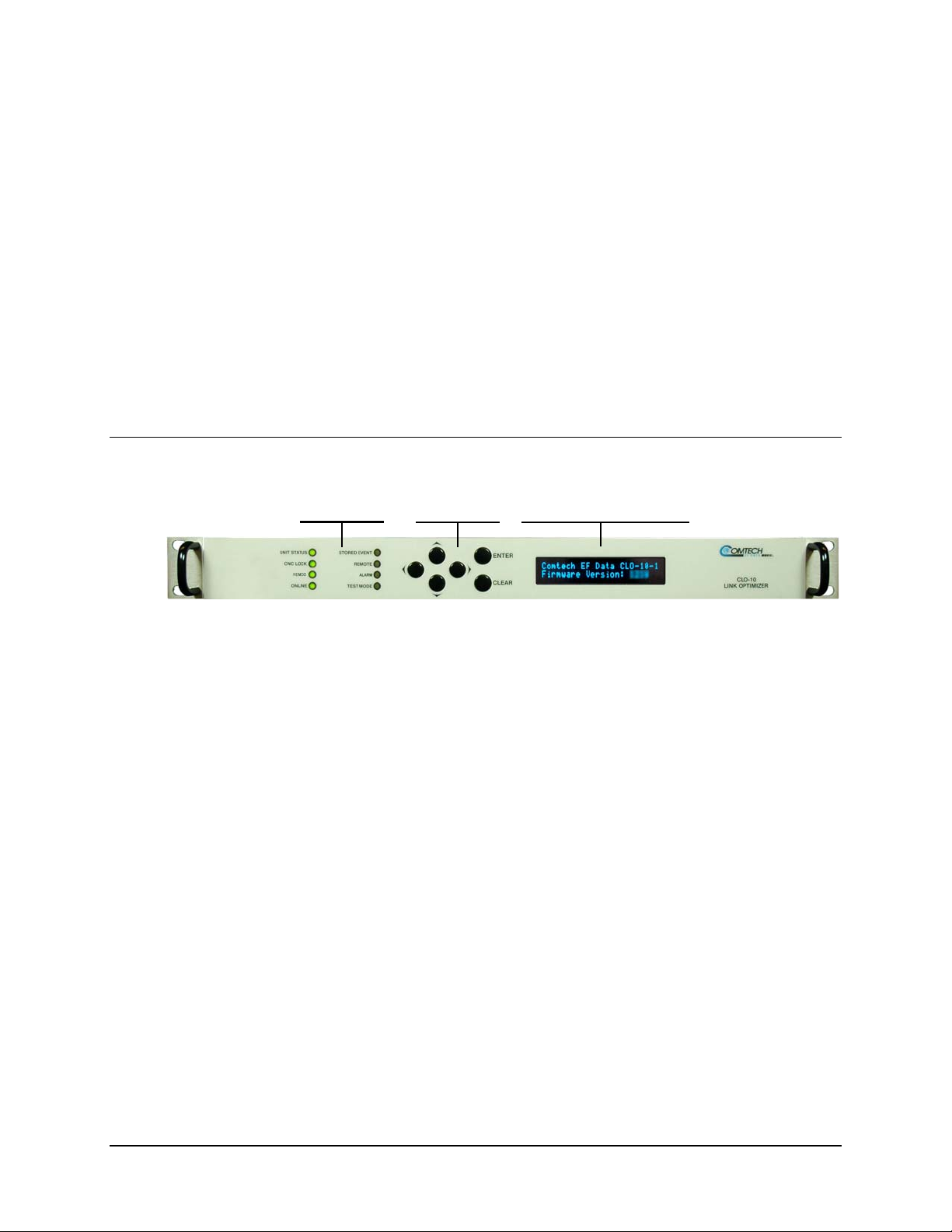
6.1 Introduction
LED Vacuum Fluorescent
The user can fully control and monitor the operation of the CLO-10 from the front panel using the
keypad and display. Nested menus are used, which display all available options, and prompt the
user to carry out a required action.
Figure 6-1 identifies the key features of the front panel, which are explained in greater detail in
this section.
Chapter 6. FRONT PANEL
OPERATION
Indicators Keypad Display (VFD)
Figure 6-1. CLO-10 Front Panel
6–1
Page 58

CLO-10 Link Optimizer Revision 1
Front Panel Operation MN/CLO-10.IOM
6.1.1 LED Indicators
The eight LEDs positioned to the left side of the front panel reflect the
operating condition of the CLO-10 Link Optimizer.
The function of these LEDs is as follows:
LED Color Condition
A Unit Fault exists (Unit Fault includes Uplink, Downlink, and
UNIT STATUS
Red
Green
Remod faults).
Example: PSU fault
No Unit Faults exist.
CNC LOCK
REMOD
ONLINE
STORED
EVENT
REMOTE
Green
Off
Green
Off
Green
Green
(flashing)
Off
Orange
Orange
(flashing)
Off
Orange
Off
CnC has acquired the delay and frequency offset of the uplink
and is suppressing it on the downlink side.
CnC is not locked.
The output to the demod (remodulator) is ON.
The remodulation transmitter is currently OFF.
The Unit is Online and carrying traffic. This LED should always
be on in single-thread (non-redundancy) systems.
The Traffic Unit is bridged or in “Hot Standby” – verifies that the
Redundant Unit is configured identically to this unit.
The Unit is Offline (standby) - forced by externally connected
1:1 or 1:N redundancy system.
There is a Stored Event in the log, which can be viewed from
the front panel or retrieved via the remote control interface.
CAUTION: The Redundant Unit is in Manual mode.
There are no Stored Events.
The Unit is in Remote Mode - Local monitoring is possible, but
Local control is not.
The Unit is in Local Mode - Remote monitoring is possible, but
Remote control Is not.
ALARM
TEST MODE
Orange
Off
Orange
Off
An Alarm exists (includes Unit, Uplink, Downlink and Remod
Alarms).
No Alarms exist.
One of the Test Modes is enabled.
Unit operating in Normal mode.
6–2
Page 59

CLO-10 Link Optimizer Revision 1
Front Panel Operation MN/CLO-10.IOM
6.1.2 Keypad
The keypad on the front panel contains six individual key switches
with a positive “click” action for tactile feedback.
The function of these keys is as follows:
ENTER
CLEAR
◄ ►
(Left, Right)
▲ ▼
(Up, Down)
IMPORTANT
This key is used to display a selected function or to execute a modem
configuration change.
This key is used to back out of a selection or to cancel a configuration
change which has not been executed using ENTER. Pressing CLEAR
generally returns the display to the previous selection.
These arrows are used to move to the next selection or to move the cursor
position. Space permitting, most of the menus include arrow key hints to
guide the user.
These arrows are used primarily to change configuration data (numbers),
at the current cursor position. Occasionally they may be used to scroll
through a number of choices at the current cursor position. Space
permitting, most of the menus include arrow key hints to guide the user.
The keypad has an auto-repeat feature. If a key is held down for more
than 1 second, the key action will repeat, automatically, at the rate of 15
keystrokes per second. This is particularly useful when editing numeric
fields, with many digits, such as frequency or data rate.
6–3
Page 60

CLO-10 Link Optimizer Revision 1
Front Panel Operation MN/CLO-10.IOM
6.1.3 Vacuum Fluorescent Display (VFD)
This ‘welcome screen’ is displayed whenever power is
first applied to the unit.
The display has two lines each of 24 characters. As shown, the first line identifies the unit model
(CLO-10-1 or CLO-10-2); the second line displays the CLO-10’s installed firmware version (this
number will vary).
Pressing any key takes the user to the top-level Select menu.
On most menu screens, users will see a flashing, solid-block cursor. This indicates the currently
selected item, digit, or field:
CONFIG: Remote BW Uplink
Downlink Remod CnC Misc
Where this solid block cursor would obscure the item being edited (for example, a numeric field),
the cursor will automatically change to an underline cursor:
Attenuation:
00.0 dB (◄ ► ▲ ▼ ENTER)
To prevent the display from becoming burnt by a constant image, the unit employs a screen saver
feature, which activates after one hour and constantly scrolls and wraps a message across the screen.
The top line of the screen saver display shows the Circuit ID (which can be entered by the user); the
bottom line shows the Carrier-in-Carrier
key…’ as shown:
Circuit ID: ------------ CnC not locked - Press any key...
Press any key to restore the previously active screen.
®
(CnC) lock status followed by the message ‘Press any
6–4
Page 61

CLO-10 Link Optimizer Revision 1
Front Panel Operation MN/CLO-10.IOM
6.2 CLO-10 Menu Structure
Figure 6-2 shows the menu structure of the CLO-10. The menu, branches, and applicable
submenus are described in detail in the chapter sections that follow.
Figure 6-2. CLO-10 Menu Tree
6–5
Page 62

CLO-10 Link Optimizer Revision 1
Front Panel Operation MN/CLO-10.IOM
6.3 Main (Top-level Select) Menu
MAIN MENU: Config Mon
Test Info Save/Load Util
Move the cursor to the desired menu branch choice using the ◄ ► arrow keys, then press
The following table describes the function of each menu branch (along with the section in this
chapter that provides detailed information on that branch and its accompanying submenus).
ENTER.
Selection
(Chapter Sect.)
Config
(6.4)
Mon
(6.5)
Test
(6.6)
Info
(6.7)
Save/Load
(6.8)
Util
(6.9)
Menu Branch Description
(Configuration) Permits the user to fully configure the unit.
(Monitor) Permits the user to monitor the alarm status of the unit,
view the log of stored events, display the CnC parameters, and
monitor the temperature of the base unit.
Permits the user to invoke one of several test modes (e.g.,
Loopback).
(Information) Permits the user to view information on the unit
without having to go into configuration screens.
Permits the user to save and load up to 10 different unit configurations.
(Utility) Permits the user to perform miscellaneous functions, such
as setting the Real-time clock, adjusting the display brightness, etc.
6–6
Page 63

CLO-10 Link Optimizer Revision 1
Front Panel Operation MN/CLO-10.IOM
6.4 CONFIG (Configuration)
CONFIG: Remote BW Uplink
Downlink Remod CnC Misc
Move the cursor to the desired choice using the ◄ ► arrow keys, then press
The submenus available under the Configuration menu branch are as follows:
ENTER.
Selection
(Chapter Sect.)
Remote
(6.4.1)
BW
( 6.4.2)
Uplink
(6.4.3)
Downlink
( 6.4.4)
Remod
( 6.4.5)
Submenu Description
Permits the user to define whether the unit is being controlled locally
or remotely.
NOTE: The unit may be monitored over the remote control bus at any
time. When in Local mode, however, configuration parameters may only
be changed through the front panel. Conversely, when in Remote
mode, the unit may be monitored from the front panel, but configuration
parameters may only be changed via the remote control bus.
Permits the user to define the bandwidth parameter for the link
optimizer.
Permits the user to define, on a parameter-by-parameter basis, the
uplink configuration of the unit.
Permits the user to define, on a parameter-by-parameter basis, the
downlink configuration of the unit.
Permits the user to define, on a parameter-by-parameter basis, the
remodulator (CLO-10 output to the demod) configuration of the unit.
CnC
(6.4.6)
Misc
(6.4.7)
Permits the user to define the minimum and maximum search delays,
and the frequency offset parameters.
Permits the user to set alarm masks, choose between the 10MHZ
internal reference or phase lock to an externally applied reference,
and enable/disable redundant operations for units equipped for this
optional functionality (refer to Appendix A. REDUNDANCY SYSTEM
OPERATION for detailed information on this option).
6–7
Page 64

CLO-10 Link Optimizer Revision 1
Front Panel Operation MN/CLO-10.IOM
6.4.1 CONFIG: Remote
Remote Control: Local
Serial Ethernet (◄ ► ENT)
Select Local, Serial, or Ethernet using the ◄ ► arrow keys, then press
ENTER. If Local is
selected, then remote control is disabled. Remote monitoring is still possible.
CONFIG: Remote Æ Serial
If Serial is selected:
Serial Config: Interface
Baudrate (◄ ► ENT)
CONFIG: Remote Æ Serial Æ Interface
If Interface is selected:
Serial Interface: RS232
RS485-2W RS485-4W (ENT)
Select RS232, RS485-2W (2-wire) or RS485-4W (4-wire) using the ◄ ► arrow keys, then press
ENTER. Here, the user is further prompted to enter the bus address.
If RS232 is selected, the following menu is displayed:
In RS-232 Mode, Serial Bus
Base Address is fixed @ 0000
CONFIG: Remote Æ Serial Æ Interface Æ RS485-2W or RS485-4W
If the unit is configured as a Redundant Unit and the Redundant feature has
been enabled, refer to Appendix A. REDUNDANCY SYSTEM OPERATION for
IMPORTANT
If either RS-485 mode is selected, and this unit is not configured as a Redundant Unit and the
Redundant feature has not been enabled, the user is further prompted:
Edit the RS-485 bus address of this unit by selecting the digit to be edited using the ef arrow
keys. The value of the digit is then changed using the d c arrow keys. The valid range of
addresses is from 1 to 9996.
detailed information on the front panel operations associated with redundancy.
RS-485 Bus Address: 0245
(◄ ► ▲ ▼ ENT)
Once the bus address is edited, the user should press ENTER.
6–8
Page 65

CLO-10 Link Optimizer Revision 1
Front Panel Operation MN/CLO-10.IOM
CONFIG: Remote Æ Serial Æ Baudrate
If Baudrate is selected:
Edit the baud rate of the remote control bus, connected locally to the M&C computer. The value is
changed using the c d arrow keys. Values of 2400, 4800, 9600, 19200, 38400, and 57600 baud
are possible. Note that the asynchronous character format is FIXED at 8 data bits, 1 stop bit, no
parity (8-N-1).
Local M&C Bus Baud Rate:
19200 Baud (▲ ▼ ENT)
Once the baud rate is edited, the user should press
ENTER.
CONFIG: Remote Æ Ethernet
If Ethernet is selected:
Ethernet Config: Gateway
Address MAC (◄ ► ENT)
CONFIG: Remote Æ Ethernet Æ Gateway
If Gateway is selected:
Ethernet IP Gateway:
192.128.001.001 (ENT)
Edit the IP Gateway Address for the Ethernet M&C port for this unit by selecting the digit to be
edited, using the ◄ ► arrow keys. The value of the digit is then changed using the ▲ ▼ arrow
keys. The user should then press
ENTER.
CONFIG: Remote Æ Ethernet Æ Address
If Address is selected:
Ether IP Address/Range:
192.168.001.001/24 (ENT)
Edit the IP Address and Range for the Ethernet M&C port for this unit by selecting the digit to be
edited, using the ◄ ► arrow keys. The value of the digit is then changed using the ▲ ▼ arrow keys.
The user should then press
ENTER.
CONFIG: Remote Æ Ethernet Æ MAC
If MAC is selected, a read-only window displays , for the user’s reference, the factory program
MAC address for the Ethernet management interface:
6–9
Page 66

CLO-10 Link Optimizer Revision 1
Front Panel Operation MN/CLO-10.IOM
M&C Port MAC Address:
00-06-B0-00-00-D5
6.4.2 CONFIG: BW (Bandwidth)
Bandwidth:
00256 kHz (◄ ► ▲ ▼ ENT)
Edit the bandwidth (decimation bandwidth) for this unit. The value of the bandwidth is changed using
the ▲ ▼ arrow keys. Values of 256, 512, 1024, 2048, 4096, 8192 and 10,000 kHz are possible.
Once the bandwidth is edited, the user should press
ENTER.
6.4.3 CONFIG: Uplink (Uplink Frequency)
Uplink Frequency:
0070.0000 MHz (◄ ► ▲ ▼ ENT)
Edit the IF Uplink Frequency by selecting the digit to be edited, using the W X arrow keys. The
value of the digit is then changed using the ST arrow keys. The range of frequencies is 50-90
MHz and 100-180 MHz with a resolution of 100 Hz.
Once the uplink frequency is edited, the user should press
ENTER.
6.4.4 CONFIG: Downlink (Downlink Frequency)
Downlink Frequency:
0070.0000 MHz (◄ ► ▲ ▼ ENT)
Edit the IF Downlink Frequency by selecting the digit to be edited, using the W X arrow keys. The
value of the digit is then changed using the ST arrow keys. The range of frequencies is 50-90
MHz and 100-180 MHz with a resolution of 100 Hz.
Once the downlink frequency is edited, the user should press
6–10
ENTER.
Page 67

CLO-10 Link Optimizer Revision 1
Front Panel Operation MN/CLO-10.IOM
6.4.5 CONFIG: Remod (Remodulation Parameters)
Remod: Frequency On/Off
Attenuation (◄ ► ENT)
Select Frequency, On/Off, or Attenuation using the ◄ ► arrow keys, then press
ENTER.
CONFIG: Remod ÆFrequency
If Frequency is selected:
Remod: Frequency
0070.0000 MHz (◄ ► ▲ ▼ ENT)
Edit the IF Remod Frequency by selecting the digit to be edited, using the W X arrow keys. The
value of the digit is then changed using the ST arrow keys. The range of frequencies is 50-90
MHz and 100-180 MHz with 100 Hz resolution.
Once the IF Remod Frequency is edited, the user should press
ENTER.
CONFIG: Remod Æ On/Off
If On/Off is selected:
Output State: Off On
(◄ ► ENT)
Edit the Output State for this unit. Select either On or Off using the W X arrow keys, then press
ENTER.
CONFIG: Remod Æ Attenuation
If Attenuation is selected:
Edit the Attenuation for this unit. Editing the value is accomplished by selecting the digit to be
edited, using the W X arrow keys. The value of the digit is then changed using the ST arrow
keys. The range varies 0-31.5 dB in 0.5 dB steps.
Once the Attenuation is edited, the user should press
Attenuation:
00.0 dB (◄ ► ▲ ▼ ENT)
ENTER.
6–11
Page 68

CLO-10 Link Optimizer Revision 1
Front Panel Operation MN/CLO-10.IOM
6.4.6 CONFIG: CnC (Carrier-in-Carrier© Parameters)
CnC: SearchDelay
FrequencyOffset (◄ ► ENT)
Select SearchDelay or Frequency Offset using the ◄ ► arrow keys, then press
ENTER.
CONFIG: CnC Æ SearchDelay
LinkDelay 100(ms)
DelayRange 025(ms) (◄ ► ▲ ▼)
The Search Delay actually represents a minimum and maximum delay value, and consists of two
parameters: Link Delay and Delay Range. The Link Delay is an estimate of the round trip delay of
the earth station to the Satellite. The Delay Range extends on either side of the Link Delay.
For example: if the user enters a Link Delay of 100 ms and a Delay Range of 10 ms, then the
actual Search Delay Range will be a minimum value of 90 ms and a maximum value of 110 ms.
Edit the Link Delay in milliseconds by selecting the digit to be edited, using the W X arrow keys.
The value of the digit is then changed using the STarrow keys.
Edit the Delay Range in milliseconds by selecting the digit to be edited, using the W X arrow keys.
The value of the digit is then changed using the STarrow keys. The user should then press ENTER.
CONFIG: CnC Æ FrequencyOffset
CnC Frequency Offset:
+/-015 kHz (◄ ► ▲ ▼ ENT)
Edit the CnC Frequency Offset. The value of the digit is changed using the ST arrow keys. The
user should then press
ENTER.
6.4.7 CONFIG: Misc: (Miscellaneous Configurations)
Misc: Mask Reference
Redundancy (◄ ► ENT)
Select Mask, Reference, or Redundancy using the ◄ ► arrow keys, then press ENTER.
CONFIG: Misc: Æ Mask
Alarm Mask: Unit
Uplink Downlink (◄ ► ENT)
Select Unit, Uplink, or Downlink using the ◄ ► arrow keys, then press ENTER.
6–12
Page 69

CLO-10 Link Optimizer Revision 1
Front Panel Operation MN/CLO-10.IOM
CONFIG: Misc: Æ Alarm Mask: Æ Unit
Unit Alarm Mask: ◄ ►
ERC ACQ_FAIL (ENT)
Select ERC or ACQ_FAIL using the ◄ ► arrow keys, then press ENTER.
CONFIG: Misc: Æ Alarm Mask: Æ Unit Alarm Mask: Æ ERC
Unit Ext Ref Clk Alarm:
Active Masked (◄ ► ENT)
CONFIG: Misc: Æ Alarm Mask: Æ Unit Alarm Mask: Æ ACQ_FAIL
Unit Acq Failure Alarm:
Active Masked (◄ ► ENT)
For the Unit Alarm Mask ERC (Unit External Reference Clock) or ACQ_FAIL (Unit
Acquisition Failure) selections (as shown above), the user is prompted to select Active, whereas
the External Reference Clock alarm or Acquisition Failure alarm activates the fault relay, or
Mask, whereas the respective fault relay will not be activated.
Once Active or Masked is selected using the ◄ ► arrow keys, the user should then press
ENTER.
CONFIG: Misc: Æ Alarm Mask: Æ Uplink
Uplink AGC Alarm Mask:
Active Masked (◄ ► ENT)
The user is prompted to select Active, whereas the Uplink AGC alarm activates the fault relay, or
Mask, whereas the fault relay will not be activated.
Once Active or Masked is selected using the ◄ ► arrow keys, the user should then press
ENTER.
CONFIG: Misc: Æ Alarm Mask: Æ Downlink
Downlink AGC Alarm Mask:
Active Masked (◄ ► ENT)
The user is prompted to select Active, whereas the Downlink AGC alarm activates the fault relay,
or Mask, which deactivates the fault relay.
Once Active or Masked is selected using the ◄ ► arrow keys, the user should then press
ENTER.
6–13
Page 70

CLO-10 Link Optimizer Revision 1
Front Panel Operation MN/CLO-10.IOM
CONFIG: Misc: Æ Reference (Reference Oscillator)
The CLO-10 can accept an externally supplied frequency reference, using the BNC connector on
the rear panel. However, rather than bypassing the internal reference and substituting the external
signal, the internal reference is used in a low-bandwidth (~ 2Hz) phase-locked loop (PLL); for
this reason, the CLO-10 actually phase locks to the external reference signal.
Edit the configuration and value of the frequency reference. The value is changed using the
STarrow keys. Values of Internal 10 MHz, External 01 MHz, External 02 MHz, External
05 MHz, External 10 MHz and Auto are possible.
Once the configuration has been edited, the user should press
Auto will detect the following external frequency references: 01 MHz, 02 MHz, 05 MHz and 10 MHz.
If the external reference frequency is invalid or no external reference frequency is connected, then
Auto – XX will be displayed.
Four examples are shown below:
Frequency Reference: ▲ ▼
Internal 10 MHz (ENT)
Frequency Reference: ▲ ▼
External 05 MHz (ENT)
Ext Reference Auto Det
Auto - 05 MHz
Ext Reference Auto Det
Auto - XX
ENTER.
CONFIG: Misc: Æ Redundancy
The CLO-10 can be optionally configured to operate within 1:1 through 1:12 redundancy
configurations. Refer to
information on the front panel operations associated with redundancy.
Appendix A. REDUNDANCY SYSTEM OPERATION for detailed
6–14
Page 71

CLO-10 Link Optimizer Revision 1
Front Panel Operation MN/CLO-10.IOM
6.5 Monitor
Monitor: Alarms Event Log
CnC Temp RSL (◄ ► ENT)
Select Alarms, Event Log, CnC, Temp, or RSL using the ◄ ► arrow keys, then press
ENTER.
6.5.1 Monitor: Alarms (Live Alarms)
Live Alarms: Unit Uplink
Downlink Remod (◄ ► ENT)
Select Unit, Uplink, Downlink, or Remod using the ◄ ► arrow keys, then press
The CLO-10 uses a system of Fault Prioritization. In each category of
fault, only the highest priority fault is displayed. This also holds true for
the faults reported via the remote control.
ENTER.
IMPORTANT
The ST arrow keys will display each fault and its current status. This will
also allow the user to display all of the possible alarms as OK or FAULT.
A comprehensive list of faults is shown at the end of this section.
Monitor: Alarms Æ (Live Alarms:) Unit (Unit Alarms)
If Unit is selected:
Unit: Fault ▲ ▼
+5V under voltage
The screen indicates if there are any Unit Faults and displays the highest priority fault. If there
are no faults, the screen displays ‘
Press
ENTER to return to the previous menu. In the case where multiple faults have occurred,
each of the possible faults can be viewed using the ST arrow keys. The display also indicates
the status of each fault (
Fault or None).
The comprehensive list of Unit faults is as follows:
• +5V PSU (+5 Volt PSU is under voltage)
None’.
• +12V PSU (+12 Volt PSU is under voltage)
• -12V PSU (–12 Volt PSU is under voltage)
• Ext Ref PLL (External Reference PLL)
• SW MGC RU (Switch Redundant Unit Configuration)
6–15
Page 72

CLO-10 Link Optimizer Revision 1
Front Panel Operation MN/CLO-10.IOM
• CnC lock (Loss of lock)
• Ext Ref Clock (External Reference Clock)
• SW Comm TU (Traffic Unit Communications)
• SW FLT TU (Traffic Unit Fault)
• SW INV CFG (Invalid Configuration, Traffic Unit Fault)
Monitor: Alarms Æ (Live Alarms:) Uplink (Uplink Alarms)
If Uplink is selected:
Uplink: Fault ▲ ▼
1ST LO Synth Lock
The screen indicates if there are any Uplink Faults and displays the highest priority fault. If there
are no faults, the screen displays ‘
Press
ENTER to return to the previous menu. In the case where multiple faults have occurred,
each of the possible faults can be viewed using the ST arrow keys. The display also indicates
the status of each fault (
Fault or None).
None’.
The comprehensive list of Uplink Faults is as follows:
ST
• 1
• 2
LO Synthesizer not locked
Nd
LO Synthesizer not locked
• AGC out of range
Monitor: Alarms Æ( Live Alarms:) Downlink (Downlink Alarms)
If Downlink is selected:
The screen indicates if there are any Downlink Faults and displays the highest priority fault. If
there are no faults, the screen displays ‘
Press
each of the possible faults can be viewed using the ST arrow keys. The display also indicates
the status of each fault (
The comprehensive list of Downlink Faults is as follows:
Downlink: Fault ▲ ▼
1ST LO Synth Lock
None’.
ENTER to return to the previous menu. In the case where multiple faults have occurred,
Fault or None).
ST
• 1
• 2
LO Synthesizer not locked
Nd
LO Synthesizer not locked
• AGC out of range
6–16
Page 73

CLO-10 Link Optimizer Revision 1
Front Panel Operation MN/CLO-10.IOM
Monitor: Alarms Æ( Live Alarms:) Remod (Remod Alarms)
If Remod is selected:
The screen indicates if there are any Remod Faults and displays the highest priority fault. If there
are no faults, the screen displays ‘None’.
Press
each of the possible faults can be viewed using the ST arrow keys. The display also indicates
the status of each fault (
The comprehensive list of Uplink Faults is as follows:
Remod: Fault ▲ ▼
1ST LO Synth Lock
ENTER to return to the previous menu. In the case where multiple faults have occurred,
Fault or None).
ST
• 1
• 2
LO Synthesizer not locked
Nd
LO Synthesizer not locked
6.5.2 Monitor: Event Log (Stored Events)
Stored Events:
View Clear-All (◄ ► ENT)
Select View or Clear-All using the ◄ ► arrow keys, then press
If View is selected:
In this example, a Remod 1
The user may scroll backwards or forwards through the entries in the event log, using the ST
arrow keys. Pressing
The event log can store up to 255 events. When a fault condition occurs, it is time-stamped and
put into the log. Similarly, when the fault condition clears, this is also recorded, as shown:
Log 023: 30/11/07 10:37:32
Fault – Remod 1ST LO (▲ ▼)
st
LO fault occurred on Nov. 30, 2007 at 10:37:32 with log number 23.
ENTER or CLEAR takes the user back to the previous menu.
Log 024: 30/11/07 10:37:35
Clear – REMOD 1ST LO (▲ ▼)
ENTER.
6–17
Page 74

CLO-10 Link Optimizer Revision 1
Front Panel Operation MN/CLO-10.IOM
If Clear-All is selected, the user is prompted to confirm that all events will be erased from the
event log:
Clear All Stored Events?
No Yes
The user must select
No or Yes using the ST arrow keys, then press ENTER to proceed.
Once the event log is cleared, the user is taken directly back to the previous menu. However, if
there are faults present on the unit at this time, they will be re-time-stamped, and new log entries
will be generated.
Note that, in accordance with international convention, the event log
IMPORTANT
shows dates in DAY/MONTH/YEAR format.
6.5.3 Monitor: CnC (Carrier-in-Carrier®)
CnC: Delay = 100.0 ms
Frequency = +001.0 kHz
Monitor: CnC provides the user with current Carrier-in-Carrier
• Delay: CnC delay I n milliseconds
• Frequency: CnC frequency offset in kHz
6.5.4 Monitor: Temp
Ambient Temperature
+037 C
Monitor: Temp provides the user with current ambient temperature in degrees Celsius.
6.5.5 Monitor: RSL (Receive Signal Level)
[ _ _ _ _ _ _ _ _ _ _ _ ]
Monitor: RSL provides the user with a virtual ‘peak meter’ that displays the approximate
strength, from 0% to 100%, of the AGC signal currently being received by the CLO-10.
Downlink RSL
®
parameters:
6–18
Page 75

CLO-10 Link Optimizer Revision 1
Front Panel Operation MN/CLO-10.IOM
6.6 TEST
TEST: Mode LampTest
(◄ ► ENT)
Select Mode or LampTest using the ◄ ► arrow keys, then press
If the user selects Mode:
TEST: Norm Bypass
Uplink CW 1010 (◄ ► ENT)
The user may select Norm , Bypass, Uplink, CW, or 1010 test modes using the ◄ ► arrow
keys, then press
ENTER. The function of each test mode selection is as follows:
ENTER.
Selection
Norm
Bypass
Uplink
CW
1010
Test Description
Any test modes or loopbacks are cleared, and the unit is placed back into an
operational state.
The downlink signal is sent out to the demod with the CnC canceller disabled. T his
is useful for checking integrity of inbound link; however, the outbound modulator
must be turned off.
The uplink carrier is sent back to the near end demodulator. This test mode can be
used to close an external RF loop on the near-end modem.
A pure carrier (no modulation) is transmitted out the remodulator.
An alternating 1010 pattern is sent to the remodulator. This test mode is used for
checking the carrier suppression of the mixers.
If the user selects LampTest, a visual test is conducted on the front panel display and LEDs to
verify that they are operational.
6–19
Page 76

CLO-10 Link Optimizer Revision 1
Front Panel Operation MN/CLO-10.IOM
6.7 INFO (Information)
INFO: Remote Bw Uplink
Downlink Remod CnC Ref
These screens display information on the current configuration of the unit. Select Remote, Bw,
Uplink, Downlink, Remod, CnC or Ref using the ◄ ► arrow keys, then press
ENTER.
INFO: Remote (Remote Control Information)
Select INFO: Remote to show if the unit is in Local or Remote mode; the display gives details
of the selected electrical interface type, the unit’s address, the selected baud rate, etc., as per the
following examples:
Press
Remote M&C: Monitor Only
(Local Control only)
Remote M&C: RS485-4Wire
Address: 0001 19200 Baud
Remote M&C: 100BaseTx
IP Addr: 255.255.255.255
ENTER or CLEAR to return back to the previous menu.
INFO: Bw (Bandwidth Information)
Select INFO: Bw to display the unit’s Bandwidth:
Bandwidth:
256 kHz (ENT)
Press
ENTER or CLEAR to return back to the previous menu.
INFO: Uplink (Uplink Information)
Select INFO: Uplink to display the unit’s Uplink Frequency:
Press
Uplink:
0070.0000 MHz (ENT)
ENTER or CLEAR to return back to the previous menu.
6–20
Page 77

CLO-10 Link Optimizer Revision 1
Front Panel Operation MN/CLO-10.IOM
INFO: Downlink (Downlink Information)
Select INFO: Downlink to display the unit’s Uplink Frequency:
Downlink:
0070.0000 MHz (ENT)
Press
ENTER or CLEAR to return back to the previous menu.
INFO: Remod (Remodulation Information)
Select INFO: Remod to display the Tx Attenuation in dB, the state of the transmitter, and the
remodulation frequency.:
Press
Remod: Atten 00.0 dB
On 0070.0000 MHz (ENT)
ENTER or CLEAR to return back to the previous menu.
INFO: CnC (Carrier-in-Carrier® Information)
Select INFO: CnC to display the CnC Frequency Range and Min/Max Delays as per the following
example:
FqRg: +/- 030 kHz
Dly: LDL=320 DRG=010 ms
Where LDL = Link Delay, and DRG = Delay Range in milliseconds. Press
ENTER or CLEAR to
return back to the previous menu.
INFO: Ref (Frequency Reference)
Selecting INFO: Ref displays the source of the Frequency Reference for the CLO-10:
Press
Frequency Reference:
Internal 10 MHz (ENT)
ENTER or CLEAR to return back to the previous menu.
6–21
Page 78

CLO-10 Link Optimizer Revision 1
Front Panel Operation MN/CLO-10.IOM
6.8 SAVE/LOAD
Save/Load Configuration:
Save Load (◄ ► ENT)
These sub-menus permit the user to store or load up to 10 different modem configurations in the
non-volatile memory of the modem.
Select Save or Load using the ◄ ► arrow keys, then press
ENTER.
Save/Load: Save (Save Configuration)
If Save is selected and a location is empty, what displays is similar to the following example:
However, if the location already contains data, what displays is similar to the next example:
The user is shown the time and date stamp of the previously stored configuration, for
identification purposes.
Select the location to where the current configuration is to be stored, using the ST arrow keys,
then press
If the selected location does not contain a previously stored configuration, the following screen is
displayed:
However, if the selected location does contain a previously stored configuration, the following
screen is displayed:
The user must select
overwrites the existing configuration at the selected location.
Save Config to Loc: 9
Empty (ST ENT)
Save Config to Loc: 9
10:37:32 30/11/07 (STENT)
ENTER. Locations 1 through 10 are available.
Your Configuration has been
Saved to Location 9 (ENT)
Location 9 Contains Data!
Overwrite? No Yes (◄ ► ENT)
No or Yes using the ◄ ► arrow keys, then press ENTER. Selecting Yes
6–22
Page 79

CLO-10 Link Optimizer Revision 1
Front Panel Operation MN/CLO-10.IOM
Save/Load: Load (Load Configuration)
If Load is selected and there is a configuration stored at the selected location, what displays is
similar to the following example:
Note that the stored configuration is identified with a date and time stamp.
If the selected location contains no data, what displays is similar to the next example:
Select the location from where the current configuration is to be loaded using the ST arrow
keys, then press
If the selected location contains valid data, what displays is similar to the following example:
Press
If the selected location contains invalid data, what displays is similar to the next example:
Press
Load Config from Loc: 9
10:37:32 30/11/07(ST ENT)
Load Config from Loc: 9
Empty (ST ENT)
ENTER. Locations 1 through 10 are available.
New Config has been Loaded
From Location 9 (ENT)
ENTER or CLEAR to return back to the previous menu.
Warning! Location 9
Contains No Data! (ENT)
ENTER or CLEAR to return back to the previous menu.
6–23
Page 80

CLO-10 Link Optimizer Revision 1
Front Panel Operation MN/CLO-10.IOM
6.9 UTILITY
UTILITY: Clock Ref ID
Display Firmware FAST ◄ ►
ENTER or CLEAR to return back to the previous menu.
Press
Select Clock, Ref, ID, Display, Firmware, or FAST using the (◄ ► ▲ ▼ ENT) arrow keys,
then press
ENTER.
Utility: Clock (Real-time Clock)
Real-Time Clock:
12:00:00 24/01/08(◄ ► ▲ ▼)
Edit the time and date setting of the Real-time Clock. This is accomplished by first selecting the
digit to be edited using the ◄ ► arrow keys, then changing the value of the digit using the ▲ ▼
arrow keys. Press
ENTER when done.
Note that, in accordance with international convention, the Real-time Clock
IMPORTANT
shows dates in DAY/MONTH/YEAR format.
Utility: Ref (Reference Adjustment)
Internal 10 MHz Ref Freq
Fine Adjust:+0190 (ENT)
Fine adjustment of the Internal 10 MHz reference oscillator is possible through this menu. Use
the ST arrow keys to edit the value. The range of values is from –2048 to +2047. Once the
value has been edited, press
The numbers displayed here do not correspond to an exact frequency
increment. A user should perform this fine adjustment while using an
external frequency counter, connected to either:
IMPORTANT
a) the internal 10 MHz reference, or
) the Tx Output, set for CW, and an exact center frequency of (as an
b
ENTER.
example) 70 MHz.
6–24
Page 81

CLO-10 Link Optimizer Revision 1
Front Panel Operation MN/CLO-10.IOM
Utility: ID (Circuit Identification)
Edit Circuit ID:(◄ ► ▲ ▼ ENT)
28 CHARACTER TST MESSAGE
Edit the Circuit ID string. Only the bottom line is available (28 characters). The cursor edits the
string by selecting the position on the bottom line using the ◄ ► arrow keys, then editing the
character in that position using the ST arrow keys.
The following characters are available:
[space] ( ) * + - . / 0-9 and A-Z
Once the Circuit ID string has been edited, press
Note: Backup devices in redundant groups do not have an ID. If plug-in devices are to be
grouped, naming of the group should take precedence over assigning IDs so the group, and not
the individual devices, can be named.
ENTER.
Utility: Display (Display Brightness)
Edit Display Brightness:
100% (▲ ▼ ENT)
Brightness levels of 25%, 50%, 75% or 100% are selectable. Edit the display brightness using
the ST arrow keys. Once the desired brightness has been set, press
ENTER.
Utility: Firmware
THESE MENUS ARE FOR DIAGNOSTIC PURPOSES ONLY. DO NOT
CHANGE AN IMAGE UNLESS INSTRUCTED TO DO SO BY COMTECH
IMPORTANT
The sub-menus available through Utility: Firmware permit the user to view information about the
CLO-10 internal firmware. The modem stores two complete firmware images, and the user can
select which image will be loaded the next time the unit reboots.
Firmware Images:
Information Select (◄ ► ENT)
Select either Information or Select using the
EF DATA CUSTOMER SERVICE TECHNICIANS.
W X arrow keys, then press ENTER.
6–25
Page 82

CLO-10 Link Optimizer Revision 1
Front Panel Operation MN/CLO-10.IOM
If Information is selected:
Firmware Info: Bootrom
Image#1 Image#2 (◄ ► ENT)
The user can view information on the Bootrom and the two images. Select Bootrom, Image#1, or
Image#2 using the
W X arrow keys, then press ENTER.
If Bootrom is selected:
Bootrom: DD/MM/YY
FW/XXXXX-X- X.X.X
The user is provided information on the installed Bootrom firmware; on the top display line, the
release date is provided in DAY/MONTH/YEAR format. The bottom line provides the Firmware
release number and its installed version number.
Press
ENTER or CLEAR to return back to the previous menu.
If Image#1 or Image#2 are selected:
Image #X: Bulk
FPGA APP
For Image#1 or Image#2, select Bulk, FPGA, or APP using the
ENTER. The information viewable on these screens is as follows:
W X arrow keys, then press
Selection
Bulk
FPGA
APP
Display Description
Identifies the top-level Bulk Firmware – the overall operating system for the
CLO-10 – containing the bundled FPGA and APP (Applications) firmware.
The top display line identifies the bulk firmware release date in
DAY/MONTH/YEAR format; the bottom line identifies the installed Bulk
Firmware release number (FW/XXXXX-X) and its installed version (X.X.X).
Identifies the FPGA Firmware bundled with the Bulk Firmware installation. The
top display line identifies the firmware release date in DAY/MONTH/YEAR
format; the bottom line identifies the firmware release number (FW/XXXXX-X)
and its installed version (X.X.X).
Identifies the Applications (microprocessor operations) Firmware bundled
with the Bulk Firmware installation. The top display line identifies the firmware
release date in DAY/MONTH/YEAR format; the bottom line identifies the
firmware release number (FW/XXXXX-X) and its installed version (X.X.X).
Press
ENTER or CLEAR to return back to the previous menu.
6–26
Page 83

CLO-10 Link Optimizer Revision 1
Front Panel Operation MN/CLO-10.IOM
Utility: FAST (FAST Code Options)
FAST: Config View
Board S/N: 123456789
Comtech EF Data’s FAST (Fully Accessible System Topology) system permits the purchase and
installation of options through special authorization codes, entered remotely or through the front
panel. FAST allows immediate implementation of different options through the user interface keypad.
All FAST options are available through the basic platform unit.
Select either Config or View using the W X arrow keys, then press ENTER.
If Config is selected:
Enter the code carefully on the bottom line by using the ◄ ► arrow keys to move to each character
position, then editing the character in that position by using the ST arrow keys. Once the 20-digit FAST
Code has been correctly edited into place, press
Successfully” if the new FAST option has been accepted:
Press ENTER or CLEAR to return back to the previous menu.
If the FAST Code is rejected, however, the following message is displayed:
Press ENTER or CLEAR to return back to the previous menu.
If View is selected:
By using the ST arrow keys, the user may review the Install Status for each available option. As
shown in the preceding example, the option’s number, description, and its Install Status are
displayed either as “Installed” or “Not Installed”. Press
back to the previous menu.
Edit 20 digit FAST Code:
00000000000000000000 (ENT)
ENTER. The CLO-10 will respond with “Configured
Configured Successfully
(ENT or CLR)
FAST Code Rejected!
(ENT or CLR)
View Options: 01 (▲ ▼ ENT)
Bandwidth - Not Installed
ENTER or CLEAR to return
6–27
Page 84

CLO-10 Link Optimizer Revision 1
Front Panel Operation MN/CLO-10.IOM
Notes:
6–28
Page 85

Appendix A. REDUNDANT
A
A.1 Introduction
The Comtech EF Data CLO-10 Link Optimizer, when operating with Firmware Version 1.2.1 or
later, can be configured for redundant system operation using a distributed Daisy Chain
configuration. This appendix provides detailed information for cabling, configuration and operation
of the CLO-10 Daisy Chain Redundancy System.
A.1.1 Overview
Intended for remote or hub applications, the CLO-10 Daisy Chain Redundancy System provides
fully manual and automatic protection of CLO-10 Traffic Units from a simple 1:1 pair to a fullyconfigured 1:12 hub system.
Figure A-1 shows a CLO-10 1:1 Daisy Chain Redundancy configuration. Figure A-2 shows a
CLO-10 1:12 Daisy Chain Redundancy configuration.
The Redundancy operation is simple. The user will assign which of the Traffic Units will be part
of the redundancy system. All active Traffic Unit configurations will be “learned” by the
Redundant Unit. The Redundant Unit will then continually monitor for any faulted Traffic Units.
An automatic backup will occur if the Redundant detects a fault on any active Traffic Unit. In an
automatic backup, the Redundant Unit will first bridge the Traffic Unit by configuring itself the
same as the failed Traffic Unit. After remaining fault-free itself, the Redundant Unit will them
force the failed Traffic Unit offline and place itself online.
A High Speed Bus (HSB) provides the communications interface between the Redundant Unit
and Traffic Units.
For CLO-10 standalone operation, the units can have either interface card installed. The top-level
menu on the unit’s front panel Vacuum Fluorescent Display (VFD) identifies which card is
installed, displaying “CLO-10-1” for any unit equipped with an Input/Output Module (IOM), or
“CLO-10-2” for any unit equipped with an Input/Output Switch Module (IOSM).
For CLO-10 Redundancy, the Redundant Unit must have the IOM installed and each Traffic Unit
must have the IOSM installed.
SYSTEM OPERATION
–1
Page 86
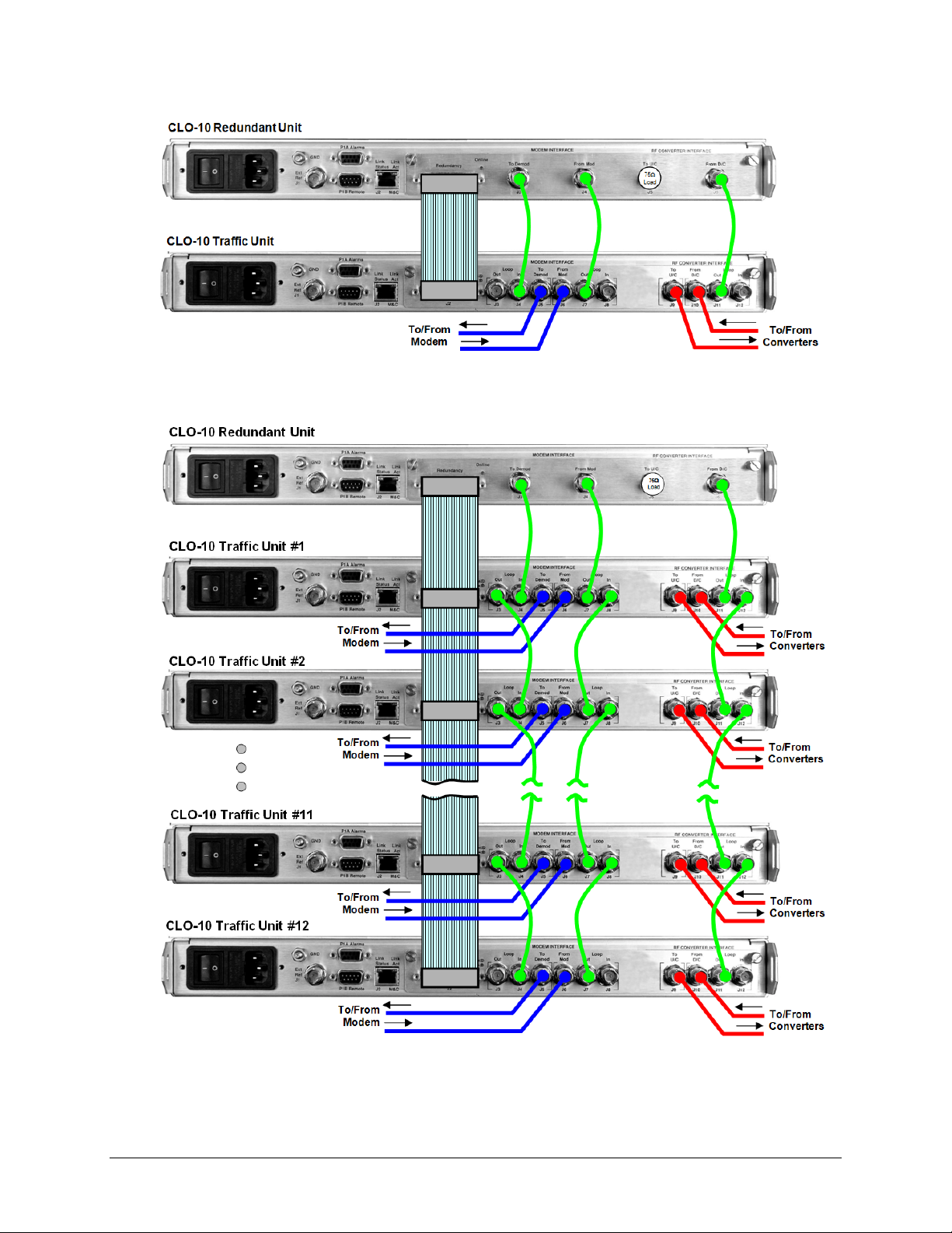
CLO-10 Link Optimizer Revision 1
Redundant System Operation MN/CLO-10.IOM
Figure A-1. CLO-10 1:1 Daisy Chain Redundancy
Figure A-2. CLO-10 1:N Daisy Chain Redundancy (1:12 shown)
A–2
Page 87

CLO-10 Link Optimizer Revision 1
Redundant System Operation MN/CLO-10.IOM
A.1.2 Redundancy System Operational Rules
For proper operation of the CLO-10 Daisy Chain Redundancy System, the operational rules
outlined in this section should be understood by the user.
General Rules:
Rule 1: Which Traffic Unit is Active? All Traffic Units are considered to be set as Active in the
examples cited in these rules. Any Traffic Unit that is not Active is not considered part of the
redundant system; it will not be polled for configuration or faults by the Redundant Unit.
Rule 2: What to Bridge? The Redundant Unit will bridge the first Traffic Unit set to Active.
Rule 3: The Redundant Unit is not under the user’s control. Any configuration change made
by the user will be overwritten on the Redundant Unit. The same is true of a Traffic Unit that is
being backed up by the Redundant Unit.
Rule 4: Which Traffic Unit has Priority? Traffic Unit #1 has the highest priority. Traffic Unit
#12 has the lowest priority.
Rule 5: Power Recovery. If the Redundant Unit loses power, the last known “Redundancy
State” will return.
For example: If Traffic Unit #2 was being backed up before power is lost, it will remain backed
up when power is restored.
For Manual Switch mode:
Rule 6: Just do it. The Redundant Unit will bridge or back up any Traffic Unit selected,
regardless of faults of the Traffic Unit or Redundant Unit.
For Automatic Switch mode:
Rule 7: Redundant Unit will back up highest priority failed Traffic Unit. Any Traffic Unit that
faults will first be bridged, then – if the Redundant Unit stays fault-free – backed up. If a Traffic
Unit loses power, the Redundant Unit will treat the incident as a Traffic Unit fault. If a fault occurs
simultaneously in two or more Traffic Units, the Redundant Unit will bridge, then back up the
Traffic Unit with the highest priority – that is, the lowest-numbered Traffic Unit will be selected
over all other Traffic Units in the redundancy system.
Rule 8: Faulted Unit is backed up. Once a Traffic Unit is Backed-up (offline) and no other
Traffic Units show faults, the Redundant Unit will stay online unless this same Traffic Unit is
now fault-free and the Redundant Unit later has faults.
Additionally, if the Redundant Unit and Traffic Unit remains fault-free and a different Traffic
Unit faults, the “restore” function will begin – the original Traffic Unit will go back online and
the Redundant Unit will bridge and back up this newly failed Traffic Unit. The other option is to
have the user take the Redundant Unit offline manually.
A–3
Page 88

CLO-10 Link Optimizer Revision 1
Redundant System Operation MN/CLO-10.IOM
A.2 Installation
For information pertaining to the CLO-10’s unpacking, inspection, and basic rack mounting instructions,
refer to Chapter 2. INSTALLATION.
Figure A-3 provides a ‘”cut-away” side view of a typical CLO-10 redundancy configuration; this example
shows up to 12 CLO-10 Traffic Units with one (1) CLO-10 Redundant Unit, for use with any combination of
modems and up and down converters (supplied by CEFD or others).
It is important to ensure that there is adequate clearance for ventilation in the rack. In rack systems where there
is high heat dissipation, provide forced-air cooling by installing top- or bottom-mounted fans or blowers.
Figure A-3. Typical Rack-mounted Redundancy Configuration
A–4
Page 89

CLO-10 Link Optimizer Revision 1
Redundant System Operation MN/CLO-10.IOM
A.3 Description of Modules
The CLO-10 can be equipped with one of two possible modules: the Input/Output Module (IOM),
or the Input/Output Switch Module (IOSM).
A.3.1.1 Overview: CLO-10 with Input/Output Module (IOM)
The CLO-10 with the Input/Output Module (IOM) can be used in two different configurations:
• As a Standalone Traffic Unit (without Daisy Chain Redundancy).
• As the Redundant Unit (for use within the Daisy Chain Redundancy).
Figure A-3 shows the IOM; Figure A-4 shows the functional block diagram of the IOM as it
operates in tandem with the CLO-10 Main Card (installed in the CLO-10 chassis).
Figure A-4. IOM (CEFD P/N PL/12833-1)
Figure A-5. CLO-10 With IOM – Block Diagram
A–5
Page 90

CLO-10 Link Optimizer Revision 1
Redundant System Operation MN/CLO-10.IOM
A.3.1.2 Overview: CLO-10 With Input/Output Switch Module (IOSM)
The CLO-10 with the Input/Output Switch Module (IOSM) can be used in two different
configurations:
• As a Standalone Traffic Unit (without Daisy Chain Redundancy).
Note: The J3, J4, J6, J7, J10, and J11 connectors are not used in this mode.
• As a Traffic Unit, from 1 up to 12 (as part of the Daisy Chain Redundancy).
Figure A-5 shows the IOSM; Figure A-6 shows the functional block diagram of the IOSM as it
operates in tandem with the CLO-10 Main Card (installed in the CLO-10 chassis).
Figure A-6. IOSM (CEFD P/N PL/12834-1)
Figure A-7. CLO-10 With IOSM – Block Diagram
A.3.2 Connector Pinouts
A.3.2.1 IOM / IOSM Redundancy Connector, J2 (DB-25F)
Typical for both the IOM and IOSM, the J2 Redundancy connector is a Type ‘D’
25-pin female connector used to connect the CLO-10 to other CLO-10s in the
optional Daisy Chain Redundancy system via the High Speed Bus (HSB) Cable
(CEFD P/N CA/RB0014-XX-U2). This cable is used to communicate between the
CLO-10-1 Redundant (controller) Unit and CLO-10-2 Traffic Unit(s).
A–6
Page 91

CLO-10 Link Optimizer Revision 1
–
r
r
Redundant System Operation MN/CLO-10.IOM
A.3.2.2 IOM / IOSM BNC Connectors
Table A-1. IOM (CEFD P/N PL/12833-1) BNC Connectors Reference
BNC Connector
To Demod J3
From Mod J4
To U/C J5
From D/C J6
Ref.
Des.
Output to Demod –signal from the downconverter with the
near-end carrier suppressed.
Input from near-end modulator – used as reference copy for
cancellation processing.
Output to Upconverter
loss.
Composite signal from Downconverter – far-end carrier
signal summed with the near-end carrier.
Description / Function Direction
same signal as J4 with up to 1.5 dB
Out
In
Out
In
Table A-2. IOSM (CEFD P/N PL/12834-1) BNC Connectors Reference
BNC Connector
Loop Out J3
Demod
Group
Mod
Group
U/C To U/C J9
D/C
Group
Loop In J4 In
To Demod J5
From Mod J6
Loop Out J7
Loop In J8 In
From D/C J10
Loop Out J11
Loop In J12 In
Ref.
Des.
Connects the previous Traffic Unit into the Daisy Chain
system.
Output to Demod –signal from the downconverter with
the near-end carrier suppressed.
Input from nea
for cancellation processing.
Connects the previous Traffic Unit into the Daisy Chain
system.
Output to Upconverter – same signal as J6 with up to 5
dB loss
Composite signal from Downconverte
signal summed with the near-end carrier.
Connects the previous Traffic Unit into the Daisy Chain
system.
Description / Function Direction
-end modulator – used as reference copy
– far-end carrier
Out
Out
In
Out
Out
In
Out
A–7
Page 92

CLO-10 Link Optimizer Revision 1
Redundant System Operation MN/CLO-10.IOM
A.4 Description of Operation
Ease of Connection: Because the redundancy switch controller resides within the CLO-10
Redundant Unit, cabling the redundancy system is remarkably simple. As shown in Chapter 4.
CABLES AND CONNECTIONS, this is accomplished using three (3) daisy-chained IF BNC
connections and a system-specific, Daisy Chain High Speed Bus (HSB) Cable.
The HSB interface serves several purposes:
• The Redundant Unit communicates with the Traffic Units via the HSB, along with
controlling all bridge and backup functions of each Traffic Unit.
• Control of each Traffic Unit is accomplished by controlling relays in the IOSMs of
the Traffic Units, via the HSB.
• The HSB does not interfere with the remote serial communication link access to any
of the Units in the chain.
Remote Operation: For user remote serial M&C communication connection to any Traffic Unit,
the user must connect only to the Redundant Unit. The Redundant Unit then passes all M&C
communications through to the appropriate Traffic Unit.
Functional Capability Requirement: Because the Redundant Unit may back up any Traffic
Unit, the Redundant Unit must be of the same or higher functional capability as the system’s
Traffic Units (i.e., FAST options).
Key Reliability Features: The CLO-10 Redundancy System incorporates the following key
reliability features:
• An IOSM can be completely removed from any Traffic Unit, with cables still
attached, without interrupting or affecting traffic, and
• An IOSM can be replaced without disturbing other Traffic circuits.
A.4.1 Bridge Mode Operation
A key feature of the CLO-10 Redundancy architecture is its ability to allow the Redundant Unit
to bridge, or mirror, a Traffic Unit. The Redundant Unit “learns” and stores each Traffic Unit’s
configuration, then configures itself to bridge the highest priority Traffic Unit’s configuration.
The Redundant Unit is able to detect faults and reconfigure itself to replace any faulted Traffic
Unit. Changes in any Traffic Unit – i.e., frequency, bandwidth, etc. – are detected by the
Redundant Unit and are immediately copied. Additionally, information is obtained automatically
by the Redundant Unit from newly added Traffic Units.
Bridge Mode allows incoming IF signals from the modem’s Tx IF and Downconverter IF to feed,
via two IF splitters on the bridged Traffic Unit’s IOSM, to both the online Traffic Unit #2 and the
Redundant Unit. These signals allow the Redundant Unit to operate under the exact same
conditions and configuration as the Traffic Unit that is being bridged. No external test equipment
is needed to determine the health of the Redundant Unit.
A–8
Page 93

CLO-10 Link Optimizer Revision 1
Redundant System Operation MN/CLO-10.IOM
Figure A-8 shows the functional block diagram of Bridge Mode. In this example, Traffic Unit #2
is being bridged and, as the figure shows, the only energized “baseball” switches are on Traffic
Unit #2.
A.4.2 Backup Mode Operation
Backup Mode is similar to Bridge Mode, with an added function: In Backup Mode, the Redundant
Unit completely replaces the Traffic Unit. More specifically, the Redundant Unit will now be
online, and the failed Traffic Unit will go offline. The output IF signal directed to the demodulator
is subsequently taken from the Redundant Unit.
Figure A-9 shows the functional block diagram of Backup Mode. In this example, Traffic Unit #2
is being backed up and, as the figure shows, all of the “baseball” switches are energized on the
IOSM on Traffic Unit #2.
Backup Mode can be done manually or automatically. In automatic mode, the Redundant Unit
will monitor all of the Traffic Units continuously. When a fault is detected on any of these active
Traffic Units, the Redundant Unit will first bridge the faulted unit, then back it up. When a
faulted Traffic Unit needs to be replaced, its IOSM can be separated from the Traffic Unit
chassis, leaving the active online Redundant Unit HSB Daisy Chain intact through the IOSM
switch module. The chain can be extended without affecting the online unit’s operation.
A–9
Page 94

CLO-10 Link Optimizer Revision 1
Redundant System Operation MN/CLO-10.IOM
Figure A-8. CLO-10 Daisy Chain Redundancy – Bridge Mode
A–10
Page 95

CLO-10 Link Optimizer Revision 1
Redundant System Operation MN/CLO-10.IOM
Figure A-9. CLO-10 Daisy Chain Configuration – Backup Mode
A–11
Page 96

CLO-10 Link Optimizer Revision 1
Redundant System Operation MN/CLO-10.IOM
A.5 Cables and Connections
Once the CLO-10s and the accompanying equipment have been mounted, the user must properly
attach all required cabling. Referring to Figure A-10 and Figure A-11, interconnection between
all equipment in the Daisy Chain Redundancy System is accomplished as follows:
• Connect Redundancy and Traffic Unit(s) using the High Speed Bus Cable, fabricated and
supplied by CEFD. This cable connects to the DB-25F J2 Redundancy connector on each
unit, and consists of as few as (2X) DB-25M connectors (for the CEFD P/N
CA/RB0014-1-U2 1:1 Cable, shown in Figure A-10) to as many as (13X) connectors (for
the CEFD P/N CA/RB0014-12-U2 1:12 Cable, shown in Figure A-11). There will be only
as many DB-25M connectors as is required for the specific 1:N Redundancy system.
IMPORTANT
• Using CEFD-supplied BNC patch cable CA/BNC75OHM, first connect the inputs and
outputs between the Redundant Unit and Traffic Unit #1; then, connect the inputs and
outputs between each Traffic Unit subsequent in the redundancy chain.
The unit’s assignment number must match that of the numbered DB-25
connector on the High Speed Bus cable (CEFD P/N CA/RB0014-XX-U2).
• For the interfaces between the CLO-10, modem, and the up and down converters, use
standard off-the-shelf 75Ω BNC male-to-BNC male patch cables, supplied by the user.
As an alternative to using off-the-shelf patch cables, the user may purchase IF Cable
PL/0813-4 (75Ω BNC male-to-BNC male, 4’) from Comtech EF Data; this cable can be
ordered at the same time the order is placed for the CLO-10 Daisy Chain Redundancy
System.
A.5.1 75Ω Load in Redundant Unit
As shown in Figure A-10 and Figure A-11, a 75Ω load (CEFD P/N CN/CXLBNCTM01) must
be installed in the J5 (“To U/C”) port on the Redundant Unit’s IOM. This load is needed to
terminate the splitter on the IOM.
A–12
Page 97

CLO-10 Link Optimizer Revision 1
Redundant System Operation MN/CLO-10.IOM
A.5.2 1:1 Redundancy Configuration Cabling
Figure A-10. CLO-10 1:1 Daisy Chain Redundancy Cabling
A–13
Page 98

CLO-10 Link Optimizer Revision 1
Redundant System Operation MN/CLO-10.IOM
A.5.3 1:N Redundancy Configuration Cabling
Figure A-11. CLO-10 1:N Daisy Chain Redundancy Cabling (1:12 shown)
A–14
Page 99

CLO-10 Link Optimizer Revision 1
Redundant System Operation MN/CLO-10.IOM
A.5.4 Adding and Removing CLO-10s and/or Modules
► To add an additional CLO-10:
Step Procedure
1 Attach all cables as outlined in A.3 CABLES AND CONNECTIONS.
2 Configure the modem and Optimizer as outlined in Chapter 4. MODEM AND
OPTIMIZER CONFIGURATION.
Figure A-12. Module Removal/Installation
► To remove a faulted Traffic Unit that is not being backed u
Step Procedure
1 De-activate the unit from the configuration.
2 Secure the module to the chassis using the (two) captive thumb screws.
3 Loosen the captive thumb screws securing the IOSM to the CLO-10 chassis. Do
not unplug the cable connections.
4 Remove the module from the chassis slot by sliding the module straight out until
it is clear of the chassis. See
NOTE: It is recommended that the unit being serviced is pushed a few inches
towards the front of the rack/cabinet in order to provide slack for the installed
HSB cable, thus easing removal of the still-cabled module.
Figure A-15.
p:
A–15
Page 100

CLO-10 Link Optimizer Revision 1
Redundant System Operation MN/CLO-10.IOM
► To replace a faulted Traffic Unit that is being backed up by the Redundant Unit:
•
CAUTION
•
Step Procedure
Do not deactivate this unit, as the Traffic path must be maintained.
1 Power-down the unit.
2 Loosen the thumb screws securing the module to the chassis. Do not unplug the
cable connections.
3 Remove the module from the chassis slot by sliding the module straight out until it
is clear of the chassis.
NOTE: It is recommended that the unit being replaced is first pushed a few
inches towards the front to the rack/cabinet in order to provide slack for the
installed HSB cable, thus easing removal of the still-cabled module.
See Figure A-15.
4 Swap out the faulted unit with the replacement CLO-10 unit.
5 Re-install the module into the replacement CLO-10 unit by inserting the module
straight into the chassis slot, using the chassis’ internal card guides.
6 Secure the module to the replacement unit using the captive thumb screws.
7 Configure the unit as outlined in Chapter 4. MODEM AND OPTIMIZER
CONFIGURATION.
►
The new Traffic Unit should lock as it is bridging the Redundant Unit. The system
will then be ready and able to cope with any other fault that may occur.
►
If desired, the user can go to AUTO-OFF (manual operation) mode, switch over
the active Traffic from the Redundant CLO-10 onto the Traffic CLO-10, and then
return to AUTO-ON (automatic operation) mode.
Figure A-13. Operating Configuration
A–16
 Loading...