

Page 1

C
i
M-25/600
IP-Enabled M&C
Installation and Operation Manual
Part Number CD/CIM25600.IOM
Rev. 3
Page 2

Page 3

Errata A
Comtech EF Data Documentation Update
Subject:
Date:
Part Number:
Related Document:
Collating Instructions:
Comments:
This information will be incorporated into the next revision.
Change Specifics:
Revise Paragraph 2.3.1 Powering the CiM-25
July 9, 2004
CD/CIM25550.IOM
CiM-25/550,IP-Enabled M&C,Installation and Operation Manual
Part Number CD/CIM25550.IOM,Rev. 2
Attach to Page 4
2.3.1 Powering the CiM-25
The CiM-25F can accept power either on pin 4 of the DB9 interface to the
equipment or via the power jack located next to the RJ-45 connector. An AC/DC
adapter is supplied to provide the CiM-26F power via the power-jack connector.
All CDM-550 modems shipped from CEFD after June 1, 2001
have been modified to supply the 5 Vdc signal on pin 4. All
units shipped from CEFD prior to this date DO NOT provide the
IMPORTANT
The CiM-25M accepts power via the power jack located next to the RJ-45
connector. An AC/DC adapter is provided to provide power to the CiM-25M.
There is no ON/OFF switch for the CiM-25.
5 Vdc on pin 4. A field modification kit is available for CDM-550
modems shipped prior to this date.
Filename: T_ERRATA 1
Page 4

Page 5
Errata Page 1 of 2
Errata B
Comtech EF Data Documentation Update
Subject:
Date:
Original Manual
Part Number/Rev:
Errata Number/
Agile Document ID:
Agile CO Number:
Comments:
Collating Instructions:
Change Specifics:
Revise Para. 2.3.1 POWERING THE CiM-25
October 27, 2009
CD/CiM25600.IOM
ER-CD_CiM25600.EB3
CO 9811
This Errata serves to void and replace Errata A (released on July 9,
2004). The information provided here will be incorporated into the
next formal manual revision.
Attach to Page 4
2.3.1 POWERING THE CIM-25
An AC/DC adapter is provided to supply power to the CiM-25 via the power-jack
connector (located next to the RJ-45 connector). There is no ON/OFF switch for the
CiM-25.
AGILE DOC ID ER-CD_CiM25600.EB3 THIS DOCUMENT IS NOT SUBJECT TO REVISION/UPDATE! AGILE CO9811
Page 6

Errata Page 2 of 2
This page is intentionally blank.
AGILE DOC ID ER-CD_CiM25600.EB3 THIS DOCUMENT IS NOT SUBJECT TO REVISION/UPDATE! AGILE CO9811
Page 7

C
Comtech EF Data is an ISO 9001
Registered Company.
i
M-25/600
IP Enabled M&C
Installation and Operation Manual
Part Number CD/CIM25600.IOM
May 13, 2004
Rev. 3
Comtech EF Data, 2114 West 7th Street, Tempe, Arizona 85281 USA, (480) 333-2200, FAX: (480) 333-2161.
Copyright © Comtech EF Data, 2001. All rights reserved. Printed in the USA.
Page 8

CiM-25/600 IP Enabled M&C Rev. 3
Preface CD/CIM25600.IOM
CUSTOMER SUPPORT
Contact the Comtech EF Data Customer Support Department for:
Product support or training
Information on upgrading or returning a product
Reporting comments or suggestions concerning manuals
A Customer Support representative may be reached at:
Comtech EF Data
Attention: Customer Support Department
2114 West 7th Street
Tempe, Arizona 85281 USA
480.333.2200 (Main Comtech EF Data Number)
480.333.4357 (Customer Support Desk)
480.333.2161 FAX
or, E-Mail can be sent to the Customer Support Department at:
cimfss@comtechefdata.com
Contact us via the web at www.comtechefdata.com.
To return a Comtech EF Data product (in-warranty and out-of-warranty) for
repair or replacement:
1. Request a Return Material Authorization (RMA) number from the
Comtech EF Data Customer Support Department.
2. Be prepared to supply the Customer Support representative with the model
number, serial number, and a description of the problem.
3. To ensure that the product is not damaged during shipping, pack the
product in its original shipping carton/packaging.
4. Ship the product back to Comtech EF Data. (Shipping charges should be
prepaid.)
For more information regarding the warranty policies, see Warranty Policy, p. xiii.
ii
Page 9

Table of Contents
Customer Support......................................................................................................................... ii
FIGURES .......................................................................................................................IX
About this Manual ........................................................................................................................ x
Conventions and References ........................................................................................................ x
Metric Conversion ........................................................................................................................ x
Recommended Standard Designations ....................................................................................... x
Trademarks ................................................................................................................................... x
EMC Compliance......................................................................................................................... xi
Federal Communications Commission (FCC) .......................................................................... xi
Safety Compliance ...................................................................................................................... xii
EN 60950 ...................................................................................................................................... xii
Warranty Policy......................................................................................................................... xiii
CHAPTER 1. INTRODUCTION.................................................................................... 1
1.1 Introduction....................................................................................................................... 1
1.2 Specifications..................................................................................................................... 2
CHAPTER 2. INSTALLATION..................................................................................... 3
2.1 Unpacking and Inspection................................................................................................ 3
2.2 Configuration .................................................................................................................... 3
2.3 Connecting CiM-25 To Equipment ................................................................................. 4
2.3.1 Powering the CiM-25.................................................................................................. 4
2.3.2 CiM-25 Connectors..................................................................................................... 4
iii
Page 10

CiM-25/600 IP Enabled M&C Rev. 3
Preface CD/CIM25600.IOM
CHAPTER 3. OPERATION.......................................................................................... 7
3.1 Overview ............................................................................................................................ 7
3.2 Administration and Security............................................................................................ 7
3.2.1 Security Tools ............................................................................................................. 8
3.2.2 Network Administration ............................................................................................. 9
3.3 HTTP Interface ............................................................................................................... 10
3.3.1 Local LAN Configuration......................................................................................... 10
3.3.2 Home Page................................................................................................................ 13
3.3.3 Logoff Page............................................................................................................... 14
3.3.4 Support Page (Common)........................................................................................... 15
3.3.5 Administration Page (Common)............................................................................... 16
3.3.6 Modem Configuration Page (Rx/Tx)........................................................................ 19
3.3.7 Status Page................................................................................................................ 20
3.3.8 Interface Parameters Page (Tx/Rx)........................................................................... 21
3.3.9 Utilities Page............................................................................................................. 22
3.3.10 Stored Faults/Alarms ................................................................................................ 23
3.3.11 CSAT-5060 and KST-2000A/B ODU Pages............................................................ 24
3.4 SNMP Interface............................................................................................................... 30
3.5 Telnet Interface ............................................................................................................... 34
3.5.1 Telnet Administrative Functions............................................................................... 35
3.5.2 Using Telnet with Equipment Remote Control Protocol.......................................... 41
3.6 Maintenance Interface.................................................................................................... 42
3.6.1 Resetting to Factory Defaults.................................................................................... 43
3.6.2 Changing Network IP Address ................................................................................. 43
3.6.3 Verifying Software Version...................................................................................... 43
3.6.4 Changing MAC Address........................................................................................... 43
3.6.5 Changing Serial Number........................................................................................... 44
APPENDIX A. CIM-25/600 SNMP INTERFACE ........................................................ 45
A.1 SNMP Interface............................................................................................................... 45
A.2 MIB-II .............................................................................................................................. 45
A.3 Private MIB Implementations ....................................................................................... 45
A.4 CiM-25 MIB Tree ........................................................................................................... 46
A.5 CiM-25 MIB .................................................................................................................... 48
A.5.1 iso.............................................................................................................................. 48
A.5.2 org ............................................................................................................................. 48
iv
Page 11

CiM-25/600 IP Enabled M&C Rev. 3
Preface CD/CIM25600.IOM
A.5.3 dod............................................................................................................................. 48
A.5.4 internet ...................................................................................................................... 48
A.5.5 private ....................................................................................................................... 48
A.5.6 enterprises ................................................................................................................. 49
A.5.7 comtech..................................................................................................................... 49
A.5.8 cim25......................................................................................................................... 49
A.5.9 cim25Objects ............................................................................................................ 49
A.5.10 ipAddress1 ................................................................................................................ 50
A.5.11 ipAddress2 ................................................................................................................ 50
A.5.12 ipAddress12Range .................................................................................................... 51
A.5.13 ipAddress3 ................................................................................................................ 51
A.5.14 ipAddress4 ................................................................................................................ 52
A.5.15 ipAddress34Range .................................................................................................... 52
A.5.16 ipAddress5 ................................................................................................................ 53
A.5.17 ipAddress6 ................................................................................................................ 53
A.5.18 ipAddress56Range .................................................................................................... 54
A.5.19 dnsIpAddressPrimary................................................................................................ 54
A.5.20 dnsIpAddressSecondary............................................................................................ 55
A.5.21 cim25IpAddress ........................................................................................................ 55
A.5.22 cim25IpGateway....................................................................................................... 55
A.5.23 cim25IpMask ............................................................................................................ 56
A.5.24 readonlyPassword ..................................................................................................... 56
A.5.25 readwritePassword .................................................................................................... 57
A.5.26 administratorPassword.............................................................................................. 57
A.5.27 trapIpAddress1.......................................................................................................... 58
A.5.28 trapIpAddress 2......................................................................................................... 58
A.5.29 trapCommunity ......................................................................................................... 58
A.5.30 administratorName.................................................................................................... 59
A.5.31 readonlyName........................................................................................................... 59
A.5.32 readwriteName.......................................................................................................... 60
A.5.33 macAddress............................................................................................................... 60
A.5.34 submitconfig ............................................................................................................. 61
A.6 CDM-600 MIB Tree: ...................................................................................................... 62
A.7 CDM-600 MIB................................................................................................................. 70
A.7.1 iso.............................................................................................................................. 70
A.7.2 org ............................................................................................................................. 70
A.7.3 dod............................................................................................................................. 70
A.7.4 internet ...................................................................................................................... 70
A.7.5 private ....................................................................................................................... 71
A.7.6 enterprises ................................................................................................................. 71
A.7.7 comtech..................................................................................................................... 71
A.7.8 cdm600...................................................................................................................... 71
A.7.9 cdm600Objects ......................................................................................................... 72
A.7.10 systemInfo................................................................................................................. 72
v
Page 12

CiM-25/600 IP Enabled M&C Rev. 3
Preface CD/CIM25600.IOM
A.7.11 equipmentID ............................................................................................................. 72
A.7.12 unitSerialNumber...................................................................................................... 73
A.7.13 softwareRevision....................................................................................................... 73
A.7.14 deviceTime................................................................................................................ 74
A.7.15 deviceDate................................................................................................................. 74
A.7.16 circuitID .................................................................................................................... 75
A.7.17 localRemoteState ...................................................................................................... 75
A.7.18 deviceTemperature.................................................................................................... 76
A.7.19 txParameters.............................................................................................................. 76
A.7.20 txFrequency............................................................................................................... 77
A.7.21 txDataRate................................................................................................................. 77
A.7.22 txModType................................................................................................................ 78
A.7.23 txFECType................................................................................................................ 79
A.7.24 txFECCodeRate ........................................................................................................ 80
A.7.25 txSpecInv .................................................................................................................. 80
A.7.26 txScrambler............................................................................................................... 81
A.7.27 txRSEncoding ........................................................................................................... 81
A.7.28 txPowerLevel ............................................................................................................ 82
A.7.29 txCarrierState ............................................................................................................ 82
A.7.30 txDataInv................................................................................................................... 83
A.7.31 rxParameters ............................................................................................................. 83
A.7.32 rxFrequency .............................................................................................................. 84
A.7.33 rxDataRate ................................................................................................................ 84
A.7.34 rxDemodType ........................................................................................................... 85
A.7.35 rxFECType................................................................................................................ 86
A.7.36 rxFECCodeRate ........................................................................................................ 87
A.7.37 rxSpecInv .................................................................................................................. 87
A.7.38 rxDescrambler........................................................................................................... 88
A.7.39 rxRSDecoding........................................................................................................... 88
A.7.40 rxDataInv .................................................................................................................. 89
A.7.41 rxAcqSweepRange.................................................................................................... 89
A.7.42 rxEbnoAlarmPoint .................................................................................................... 90
A.7.43 interfaceParameters................................................................................................... 90
A.7.44 ifImpedance............................................................................................................... 91
A.7.45 txInterfaceType......................................................................................................... 91
A.7.46 rxInterfaceType......................................................................................................... 92
A.7.47 txFramingMode......................................................................................................... 93
A.7.48 rxFramingMode ........................................................................................................ 94
A.7.49 txClockSource........................................................................................................... 95
A.7.50 rxClockSource........................................................................................................... 95
A.7.51 rxBufferSize.............................................................................................................. 96
A.7.52 externalClock ............................................................................................................ 96
A.7.53 externalReference ..................................................................................................... 97
A.7.54 txTernaryCode .......................................................................................................... 98
A.7.55 rxTernaryCode .......................................................................................................... 98
vi
Page 13

CiM-25/600 IP Enabled M&C Rev. 3
Preface CD/CIM25600.IOM
A.7.56 idrTxESCType .......................................................................................................... 99
A.7.57 idrRxESCType.......................................................................................................... 99
A.7.58 txAudioVolume....................................................................................................... 100
A.7.59 rxAudioVolume ...................................................................................................... 100
A.7.60 dropAndInsert ......................................................................................................... 101
A.7.61 txTerrestrialAlarmMask.......................................................................................... 102
A.7.62 rxTerrestrialAlarmEnable ....................................................................................... 102
A.7.63 recenterBuffer ......................................................................................................... 103
A.7.64 utilityParameters ..................................................................................................... 103
A.7.65 edmacFramingMode ............................................................................................... 104
A.7.66 edmacAddress......................................................................................................... 104
A.7.67 unitTestMode .......................................................................................................... 105
A.7.68 unitAlarmMask ....................................................................................................... 106
A.7.69 txBackwardAlarmEnable........................................................................................ 106
A.7.70 rxBackwardAlarmEnable........................................................................................ 107
A.7.71 unitConfigStore....................................................................................................... 107
A.7.72 unitConfigLoad....................................................................................................... 108
A.7.73 oduCommEnable..................................................................................................... 108
A.7.74 aupcParameters ....................................................................................................... 109
A.7.75 aupcEnable.............................................................................................................. 109
A.7.76 aupcControlParameters........................................................................................... 110
A.7.77 remoteEbno............................................................................................................. 110
A.7.78 txPowerLevelIncrease............................................................................................. 111
A.7.79 statusParameters...................................................................................................... 111
A.7.80 rxEbno..................................................................................................................... 112
A.7.81 rxSignalLevel.......................................................................................................... 112
A.7.82 rxFrequencyOffset .................................................................................................. 113
A.7.83 bufferFillState ......................................................................................................... 113
A.7.84 rxBER ..................................................................................................................... 114
A.7.85 redundancyState...................................................................................................... 114
A.7.86 unitFaults................................................................................................................. 115
A.7.87 logs.......................................................................................................................... 116
A.7.88 clearEventsLog ....................................................................................................... 117
A.7.89 numberUnreadEvents.............................................................................................. 117
A.7.90 retrieveNext5Events................................................................................................ 118
A.7.91 setStatisticInterval................................................................................................... 118
A.7.92 clearStatisticsLog.................................................................................................... 119
A.7.93 numberUnreadStatistics .......................................................................................... 119
A.7.94 retrieveNext5Statistics ............................................................................................ 120
A.7.95 trapNotifications ..................................................................................................... 120
A.7.96 trapNotificationsPrefix............................................................................................ 120
A.7.97 unitFaultTraps......................................................................................................... 121
A.7.98 unitConfigChangeTrap ........................................................................................... 122
A.7.99 csat5060Objects ...................................................................................................... 123
A.7.100 oduSelect............................................................................................................. 123
vii
Page 14

CiM-25/600 IP Enabled M&C Rev. 3
Preface CD/CIM25600.IOM
A.7.101 oduSystemInfo .................................................................................................... 123
A.7.102 oduModelNumberSoftwareVer........................................................................... 124
A.7.103 oduunitSerialNumber.......................................................................................... 124
A.7.104 odudeviceTime.................................................................................................... 125
A.7.105 odudeviceDate..................................................................................................... 125
A.7.106 oducircuitID ........................................................................................................ 126
A.7.107 oduUnitParameters.............................................................................................. 126
A.7.108 oduUnitMuteMode.............................................................................................. 127
A.7.109 oduUnitColdStart ................................................................................................ 127
A.7.110 oduUnitAutoFaultRecovery................................................................................ 128
A.7.111 oduUnitExtRefFaultLogic................................................................................... 128
A.7.112 oduUnitRefOscAdjust......................................................................................... 129
A.7.113 oduUnitLNACurrentSource................................................................................ 129
A.7.114 oduUnitLNACurrentWindow ............................................................................. 130
A.7.115 oduUnitLNAFaultLogic...................................................................................... 131
A.7.116 oduUnitRedundancyMode .................................................................................. 131
A.7.117 oduUnitRedForceSwitch..................................................................................... 132
A.7.118 oduTxParameters ................................................................................................ 132
A.7.119 odutxFrequency................................................................................................... 133
A.7.120 oduTxAttenuation ............................................................................................... 133
A.7.121 oduTxAmplifier .................................................................................................. 134
A.7.122 oduTxMute.......................................................................................................... 134
A.7.123 oduTxSlopeMode................................................................................................ 135
A.7.124 oduTxSlopeValue ............................................................................................... 135
A.7.125 oduTxGainOffset ................................................................................................ 136
A.7.126 oduRxParameters ................................................................................................ 136
A.7.127 oduRxFrequency................................................................................................. 137
A.7.128 oduRxAttenuation............................................................................................... 137
A.7.129 oduRxMute ......................................................................................................... 138
A.7.130 oduRxSlopeMode ............................................................................................... 138
A.7.131 oduRxSlopeValue ............................................................................................... 139
A.7.132 oduRxGainOffset ................................................................................................ 139
A.7.133 oduUnitStatus...................................................................................................... 140
A.7.134 oduOnlineState.................................................................................................... 140
A.7.135 oduMaintenanceParameters ................................................................................ 141
A.7.136 oduUnitFaults...................................................................................................... 141
A.7.137 oduLogs............................................................................................................... 142
A.7.138 oduClearEventsLog............................................................................................. 142
A.7.139 oduNumberUnreadEvents................................................................................... 143
A.7.140 oduRetrieveNext5Events .................................................................................... 143
A.7.141 kst2000Objects.................................................................................................... 144
A.7.142 kstSystemInfo ..................................................................................................... 144
A.7.143 kstEquipmentType .............................................................................................. 144
A.7.144 kstSerialNumbers................................................................................................ 145
A.7.145 kstAssemblyNumbers ......................................................................................... 145
viii
Page 15

CiM-25/600 IP Enabled M&C Rev. 3
Preface CD/CIM25600.IOM
A.7.146 kstFirmwareNumbers.......................................................................................... 146
A.7.147 kstUnitParameters............................................................................................... 146
A.7.148 kstCircuitID......................................................................................................... 147
A.7.149 kstAgc ................................................................................................................. 148
A.7.150 kstRefOscillatorAdjust........................................................................................ 148
A.7.151 kstLockMode ...................................................................................................... 149
A.7.152 kstTxParameters.................................................................................................. 149
A.7.153 kstUpConvFrequency ......................................................................................... 150
A.7.154 kstUpConvAttenuation ....................................................................................... 150
A.7.155 kstUpConvOutput ............................................................................................... 151
A.7.156 kstHpaPowerEnable............................................................................................ 152
A.7.157 kstHpaFaultLogic................................................................................................ 152
A.7.158 kstRxParameters ................................................................................................. 153
A.7.159 kstDownConvFrequency..................................................................................... 153
A.7.160 kstDownConvAttenuation................................................................................... 154
A.7.161 kstReceiveBand................................................................................................... 154
A.7.162 kstLnaPowerEnable ............................................................................................ 155
A.7.163 kstLnaFaultLogic ................................................................................................ 155
A.7.164 kstUnitStatus....................................................................................................... 156
A.7.165 kstUnitFaultStatus............................................................................................... 156
A.7.166 kstCommonEquipmentStatus.............................................................................. 157
A.7.167 kstReferenceStatus.............................................................................................. 158
A.7.168 kstAgcStatus ....................................................................................................... 158
A.7.169 kstUpConvStatus................................................................................................. 159
A.7.170 kstDownConvStatus............................................................................................ 159
A.7.171 kstHpaStatus ....................................................................................................... 160
A.7.172 kstLnaStatus........................................................................................................ 161
INDEX ......................................................................................................................... 163
Figures
FIGURE 1. NULL CABLE DIAGRAM ..................................................................................... 42
ix
Page 16
CiM-25/600 IP Enabled M&C Rev. 3
Preface CD/CIM25600.IOM
ABOUT THIS MANUAL
This manual provides installation and operation information for the Comtech EF Data
CiM-25/600 IP Enabled M&C. This is a technical document intended for earth station
engineers, technicians, and operators responsible for the operation and maintenance of
the CiM-25/600 IP Enabled M&C.
CONVENTIONS AND REFERENCES
CAUTIONS AND WARNINGS
Indicates information critical for proper equipment function.
IMPORTANT
CAUTION
Indicates a hazardous situation that, if not avoided, may result in minor or moderate
injury. CAUTION may also be used to indicate other unsafe practices or risks of
property damage.
Indicates a potentially hazardous situation that, if not avoided, could result in
WARN ING
death or serious injury.
METRIC CONVERSION
Metric conversion information is located on the inside back cover of this manual. This
information is provided to assist the operator in cross-referencing non-metric to metric
conversions.
RECOMMENDED STANDARD DESIGNATIONS
Recommended Standard (RS) Designations have been superseded by the new designation
of the Electronic Industries Association (EIA). References to the old designations are
shown only when depicting actual text displayed on the screen of the unit (RS-232, RS485, etc.). All other references in the manual will be shown with the EIA designations
(EIA-232, EIA-485, etc.) only.
TRADEMARKS
All product names mentioned in this manual may be trademarks or registered trademarks
of their respective companies and are hereby acknowledged.
x
Page 17

CiM-25/600 IP Enabled M&C Rev. 3
Preface CD/CIM25600.IOM
REPORTING COMMENTS OR SUGGESTIONS CONCERNING THIS MANUAL
Comments and suggestions regarding the content and design of this manual will be
appreciated. To submit comments, please contact the Comtech EF Data Customer
Support Department.
EMC COMPLIANCE
This is a Class A product. In a domestic environment, it may cause radio interference that
requires the user to take adequate protection measures.
EN55022 COMPLIANCE
This equipment meets the radio disturbance characteristic specifications for information
technology equipment as defined in EN55022.
EN50082-1 COMPLIANCE
This equipment meets the electromagnetic compatibility/generic immunity standard as
defined in EN50082-1.
FEDERAL COMMUNICATIONS COMMISSION (FCC)
This equipment has been tested and found to comply with the limits for a Class A digital
device, pursuant to Part 15 of the FCC rules. These limits are designed to provide
reasonable protection against harmful interference when the equipment is operated in a
commercial environment.
This equipment generates, uses, and can radiate radio frequency energy. If not installed
and used in accordance with the instruction manual, it may cause harmful interference to
radio communications. Operation of this equipment in a residential area is likely to cause
harmful interference, in which case users are required to correct the interference at their
own expense.
Note: To ensure compliance, properly shielded cables for DATA I/O shall be used. More
specifically, these cables shall be shielded from end to end, ensuring a continuous shield.
xi
Page 18

CiM-25/600 IP Enabled M&C Rev. 3
Preface CD/CIM25600.IOM
SAFETY COMPLIANCE
EN 60950
Applicable testing is routinely performed as a condition of manufacturing on all units to
ensure compliance with safety requirements of EN60950.
This equipment meets the Safety of Information Technology Equipment specification as
defined in EN60950.
LOW VOLTAGE DIRECTIVE (LVD)
The following information is applicable for the European Low Voltage Directive
(EN60950):
<HAR> Type of power cord required for use in the European Community.
CAUTION: Double-pole/Neutral Fusing.
!
ACHTUNG: Zweipolige bzw. Neutralleiter-Sicherung.
International Symbols:
Symbol Definition Symbol Definition
Alternating Current.
Fuse.
Protective Earth.
Chassis Ground.
Note: For additional symbols, refer to “Cautions” listed earlier in this preface.
xii
Page 19

CiM-25/600 IP Enabled M&C Rev. 3
Preface CD/CIM25600.IOM
WARRANTY POLICY
This Comtech EF Data product is warranted against defects in material and workmanship
for a period of two years from the date of shipment. During the warranty period, Comtech
EF Data will, at its option, repair or replace products that prove to be defective.
For equipment under warranty, the customer is responsible for freight to Comtech EF
Data and all related customs, taxes, tariffs, insurance, etc. Comtech EF Data is
responsible for the freight charges only for return of the equipment from the factory to
the customer. Comtech EF Data will return the equipment by the same method (i.e., Air,
Express, Surface) as the equipment was sent to Comtech EF Data.
LIMITATIONS OF WARRANTY
The foregoing warranty shall not apply to defects resulting from improper installation or
maintenance, abuse, unauthorized modification, or operation outside of environmental
specifications for the product, or, for damages that occur due to improper repackaging of
equipment for return to Comtech EF Data.
No other warranty is expressed or implied. Comtech EF Data specifically disclaims the
implied warranties of merchantability and fitness for particular purpose.
EXCLUSIVE REMEDIES
The remedies provided herein are the buyer's sole and exclusive remedies. Comtech EF
Data shall not be liable for any direct, indirect, special, incidental, or consequential
damages, whether based on contract, tort, or any other legal theory.
DISCLAIMER
Comtech EF Data has reviewed this manual thoroughly to provide an easy-to-use guide
to your equipment. All statements, technical information, and recommendations in this
manual and in any guides or related documents are believed reliable, but the accuracy and
completeness thereof are not guaranteed or warranted, and they are not intended to be,
nor should they be understood to be, representations or warranties concerning the
products described. Further, Comtech EF Data reserves the right to make changes in the
specifications of the products described in this manual at any time without notice and
without obligation to notify any person of such changes.
If you have any questions regarding the equipment or the information in this manual,
please contact the Comtech EF Data Customer Support Department.
xiii
Page 20

Page 21
Chapter 1. INTRODUCTION
CiM-25
IP-Enabled
M&C Interface
1.1 INTRODUCTION
The CiM-25 is a low-cost solution for providing an Internet Protocol (IP) Monitor and
Control (M&C) interface for existing Comtech EF Data satellite modems, RF frequency
converters and solid-state power amplifiers. The CiM-25 provides a custom proxy
interface between the IP world and the equipment’s existing serial remote control
interface.
The CiM-25 provides powerful equipment management tools via HTTP protocol, SNMP
v2c Protocol, and Telnet Protocol. Wrapped around these industry standard protocols is a
system of account access and IP security control features to safeguard equipment from
unwanted intrusions. The CiM-25 brings customer support to a new level by providing
SMTP Protocol to facilitate automated, direct E-mail to Comtech EF Data’s Customer
Support Center.
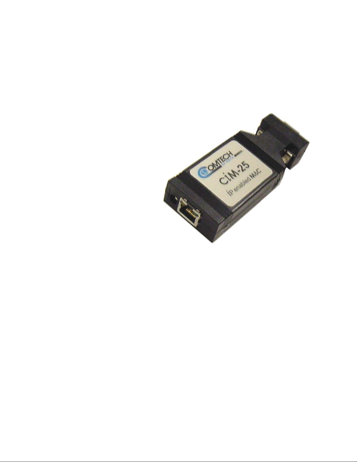
The CiM-25 is packaged in a very compact 4.3” x 1.7” x 0.8”. The unit can be powered
directly by the attached equipment or via an external AC/DC adapter. The CiM-25
requires less than 1 Watt of power.
1
Page 22

CiM-25/600 IP Enabled M&C Rev. 3
Introduction CD/CIM25600.IOM
The CiM-25 uses flash technology providing support for a wide variety of products from
a single hardware platform. The CiM-25 either currently or will in the near future support
the following Comtech EF Data equipment:
Modems
SDM-300L1* SDM-300A/SLM-3650*
SDM-300L2* CDM-550T
SDM-300L3 CDM-600*
SDM-2020M* SDM-2020D*
SDM-8000* SDM-9000*
Frequency Converter
UT4500 series 1 kHz and 125 kHz step size Up Converters*
DT4500 series 1 kHz and 125 kHz step size Down Converters*
*Requires an external 5 Vdc Power Supply (universal AC input). See section 2.3.1,
Powering the CiM-25.
1.2 SPECIFICATIONS
SYSTEM SPECIFICATIONS
Ethernet Interface 10base T (RJ-45)
Equipment Interface DB9 Female on CiM-25F
DB9 Male on CiM-25M
ENVIRONMENTAL AND PHYSICAL
Temperature Operating: 0 to 50º C
Storage: -25 to 70º C
Power Supply 4.75 to 5.25 Vdc
Power Consumption 0.9 W typical, 1.5 W maximum
Physical Dimensions L=110, W=43, H=20 (mm)
L=4.3, W=1.7, H=0.8 (inches)
Weight < 1 lbs
CE Approvals EN55022 Class B (Emissions)
EN50082-1 Part 1 (Immunity)
EN60950 (Safety)
FCC Approval FCC Part 15 Class B
2
Page 23

Chapter 2. INSTALLATION
2.1 UNPACKING AND INSPECTION
Inspect shipping containers for damage. If shipping containers are damaged, keep them
until the contents of the shipment have been carefully inspected and checked for normal
operation.
Remove the packing list from the outside of the shipping carton. Open the carton and
remove the contents, checking the contents against the packing list. Verify completeness
of the shipment and that the unit functions correctly. If damage is evident, contact the
carrier and Comtech EF Data immediately and submit a damage report. Keep all shipping
materials for the carrier's inspection.
If the unit needs to be returned to Comtech EF Data, please use the original shipping
container.
2.2 CONFIGURATION
There are no internal jumpers to configure, no interface cards to install, and no other
options to install. All configuration is carried out entirely in software. The unit should
first be configured locally, using the RJ-45 Ethernet interface. The unit will ship with a
default IP address of 10.6.30.1, Gateway 0.0.0.0, and Mask 255.255.0.0. The default
Administrator Name and Password are admin and 1234 respectively. See the operations
section for details regarding configuring and administrating the CiM-25.
3
Page 24

CiM-25/600 IP Enabled M&C Rev. 3
Introduction CD/CIM25600.IOM
2.3 CONNECTING CIM-25 TO EQUIPMENT
The CiM-25 is designed to connect directly (no cabling) to supported Comtech EF Data
Modems, Frequency Converters, or Solid State Power Amplifiers using the equipment’s
9-pin remote control interface port. The CiM-25 interfaces to this equipment via a RS232 interface at a baud rate of 19200 bps and a data format of 8-N-1. Therefore, it is
necessary to first select the RS-232 interface type on the interfacing equipment prior to
connecting the CiM-25 to said equipment. Some equipment automatically selects a unit
address of 0 when RS-232 is chosen while other equipment requires the user to configure
the unit remote control address to 1. In addition, on equipment that supports multiple data
formats the user must select 8-N-1 format.
2.3.1 POWERING THE CIM-25
The CiM-25F can accept power either on pin 4 of the DB9 interface to the equipment or
via the power jack located next to the RJ-45 connector. An optional AC/DC adapter can
be purchased to provide the CiM-25F power via the power-jack connector.
The CiM-25M accepts power via the power jack located next to the RJ-45 connector. An
AC/DC adapter must be purchased to provide power to the CiM-25M.
All CDM-550 and CDM-600 modems shipped from the factory after June 1, 2001 have
been modified to supply the 5 Vdc signal on pin 4. All units shipped from the factory
prior to this date DO NOT provide the 5 Vdc on pin 4. A field modification kit is
available and can be purchased for CDM-550 and CDM-600 modems shipped prior to
this date.
Note: There is no ON/OFF switch for the CiM-25.
2.3.2 CIM-25 CONNECTORS
There are three connectors located on each CiM-25:
RJ-45 - 10base T Ethernet interface.
DB9 – RS-232 equipment interface (either male or female)
1.3mm – DC Power Jack
The pinout details for these connectors are as follows.
4
Page 25

CiM-25/600 IP Enabled M&C Rev. 3
Introduction CD/CIM25600.IOM
RJ-45 Pin Out
Pin Function
1 Tx+
2 Tx-
3 Rx+
4 No Connection
5 No Connection
6 Rx-
7 No Connection
8 No Connection
DB9 Female (CiM-25F) DB9 Male (CiM-25M)
Pin Function
1 Ground 1 Ground
2
CiM-25 Rx
3
CiM-25 Tx
4 +5 Vdc Input 4 No Connection
5 Ground 5 Ground
6 No Connection 6 +5 Vdc Input
7 No Connection 7 No Connection
8 No Connection 8 No Connection
9 No Connection 9 No Connection
2
3
Pin Function
CiM-25 Rx
CiM-25 Tx
1.3mm – DC Power Jack
Pin Function
Center Conductor +5 Vdc Input
Outer Conductor Ground
5
Page 26

CiM-25/600 IP Enabled M&C Rev. 3
Introduction CD/CIM25600.IOM
NOTES
6
Page 27

3.1 OVERVIEW
Each CiM-25 unit is programmed in the factory to provide a custom proxy interface to
Comtech EF Data’s previously defined equipment. This means that a CiM-25/600 that is
loaded to interface a CDM-600 Modem to the IP world will not operate with any other
piece of Comtech EF Data equipment, unless the personality is changed via a flash
upload. However, every CiM-25, independent of personality, shares a large number of
common features. For instance, all CiM-25 units provide the same degree of security
features, network protocols, and administration features. The following sections will
provide a detailed description of all the features available for a specific CiM-25 (i.e.,
CiM-25/600 with CDM-600 Modem). Those areas that are common to all CiM-25 units
will be expounded upon and delineated. The areas that are specific to the individual
personality (such as equipment parameter control) will only be briefly covered since
these are already covered in detail in the individual equipment operator manuals.
Chapter 3. OPERATION
3.2 ADMINISTRATION AND SECURITY
The CiM-25 has been designed to provide a high degree of administrative flexibility to
ensure that each user can configure the device (or network of devices) in a manner that
meets his/her security needs. The primary tools provided are the Host Allow List, PING
enable/disable, and three (3) level user login. Used as a group, these three tools provide
the CiM-25 with a very high degree of security.
7
Page 28

CiM-25/600 IP Enabled M&C Rev. 3
SNMP Interface CD/CIM25600.IOM
3.2.1 SECURITY TOOLS
3.2.1.1 U
For the HTTP interfaces the CiM-25 provides three (3) levels of user login. The Telnet
interface provides the first two (2) of the following levels. The highest level is the
Administrator login. This level allows 100% complete access to all controllable CiM-25
and equipment parameters. The next level of user login is the Read/Write level. This
level allows access to all controllable equipment parameters but does not allow access to
the administration parameters of the CiM-25 itself. The lowest level of login is the Read
Only login. This level allows the user to view, but not change, the equipment parameters.
Like the Read/Write level, this level does not allow access to the administration
parameters of the CiM-25.
The Name and Password factory defaults for the three levels are:
Administrator Level:
Name: admin
Password: 1234
Read/Write Level:
Name: opcenter
Password: 1234
Read Only Level:
Name: monitor
Password: 1234
SER LOGIN
The SNMP interface uses all three (3) levels of user login utilizing the SNMP v2c
(community string) method of security. The community string is the name and password,
i.e., admin1234, default admin community string.
3.2.1.2 HOST ALLOW LIST
The CiM-25 provides a high degree of security by allowing the Administrator to define a
list of IP addresses to which the CiM-25 will accept/respond to IP datagrams. The
Administrator can select up to six (6) individual allowable IP addresses or up to three (3)
allowable IP address ranges or any combination of individual and ranges that can be
defined by six fields (see Section 3.3, HTTP Interface). The host allow list is applied to
all three CiM-25 interfaces (HTTP, SNMP, and Telnet).
3.2.1.3 PING ENABLE/DISABLE
The final piece to the CiM-25 security design is the PING Enable/Disable feature. This
feature allows the Administrator to disable PING on an individual CiM-25. This conceals
the CiM-25 from most hackers.
8
Page 29

CiM-25/600 IP Enabled M&C Rev. 3
SNMP Interface CD/CIM25600.IOM
3.2.2 NETWORK ADMINISTRATION
The CiM-25 also provides the following network administration facilities:
Configure IP Address, IP Gateway, and IP Mask.
Select Primary and Secondary DNS server IP addresses.
Select SMTP domain Name and IP address.
Select SNMP Trap IP addresses.
9
Page 30
CiM-25/600 IP Enabled M&C Rev. 3
SNMP Interface CD/CIM25600.IOM
3.3 HTTP INTERFACE
This section explains the HTTP (Web Server) interface provided by the CiM-25/600.
3.3.1 LOCAL LAN CONFIGURATION
The web page interface is best viewed at 1152 x 864 resolution using Internet Explorer
5.5 or higher and a 17” or larger monitor.
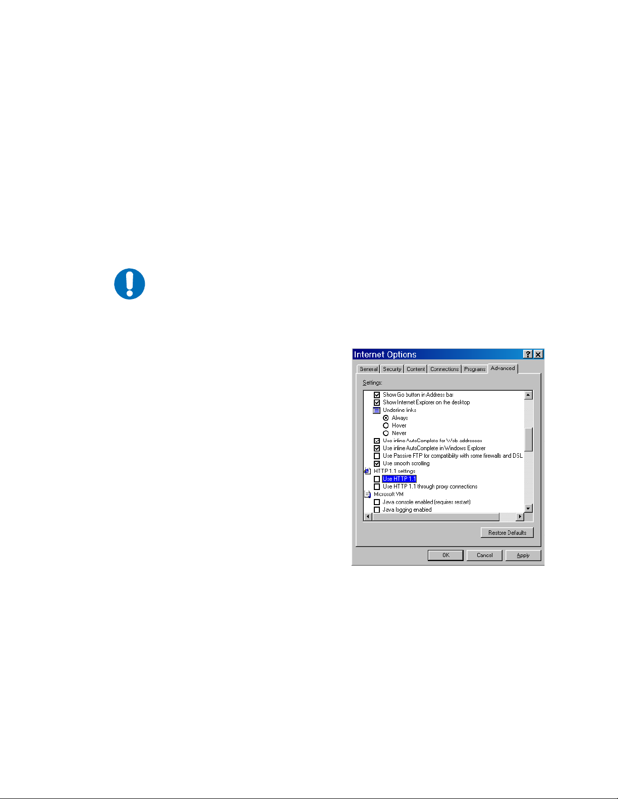
3.3.1.1 HTTP 1.1
For best performance, HTTP 1.1 should be disabled. It can be changed as follows:
IMPORTANT
Step Procedure Example
Click Start, Settings, then Control Panel.
1.
Double-click the Internet Options icon in
2.
the Control Panel.
Under the Advanced tab, scroll down to
3.
HTTP 1.1 settings.
Uncheck the Use HTTP 1.1 box and click
4.
OK.
10
Page 31

CiM-25/600 IP Enabled M&C Rev. 3
SNMP Interface CD/CIM25600.IOM
3.3.1.2 PROXY SERVER
If your network uses a proxy server, it may be necessary to disable the use of it for
IMPORTANT
Step Procedure Example
1.
2.
the browser to work. It can be changed as follows:
Click Start, Settings, then
Control Panel.
Double-click the Internet Options
icon in the Control Panel.
4.
Under the Connections tab, click
3.
the LAN Settings button.
At this point you must do one of
the following:
a. Uncheck the Use a proxy
server box and click OK.
or
b. Click the Advanced button
and go to the next step.
11
Page 32

CiM-25/600 IP Enabled M&C Rev. 3
SNMP Interface CD/CIM25600.IOM
Step Procedure Example
5.
In the Exceptions box, enter the
IP address of the CiM module and
click OK.
12
Page 33

CiM-25/600 IP Enabled M&C Rev. 3
SNMP Interface CD/CIM25600.IOM
3.3.2 HOME PAGE
Welcome to the CiM-25/600 Web Interface. The following sections will give you a brief
introduction to each web page available.
13
Page 34

CiM-25/600 IP Enabled M&C Rev. 3
SNMP Interface CD/CIM25600.IOM
3.3.3 LOGOFF PAGE
The CiM-25 allows multiple connections to the Web Interface. The Web Interface and
Telnet Interface cannot be used at the same time.You must logoff the Web Interface in
order to log into the Telnet Interface and vice versa.
14
Page 35

CiM-25/600 IP Enabled M&C Rev. 3
SNMP Interface CD/CIM25600.IOM
3.3.4 SUPPORT PAGE (COMMON)
In order to use the Support functions, the user must first assign SMTP a domain
IMPORTANT
name and IP address. Refer to 3.3.5.8, SMTP Domain Name and IP Address.
The Support page is accessible by ALL logged in users. This page allows the user to
automatically email Comtech EF Data’s Customer Support center. The user MUST fill in
the Name, Company, Email Address, and Telephone information boxes. In addition,
the user must enter some description of the problem or question into the Problem Report
field. The CiM-25 will automatically retrieve and attach pertinent information about the
equipment (such as Equipment ID, Serial Number, Configuration, and Status) to the
email message. This will allow Comtech EF Data Customer Support personnel to provide
faster and more accurate responses to customer needs.
15
Page 36
CiM-25/600 IP Enabled M&C Rev. 3
SNMP Interface CD/CIM25600.IOM
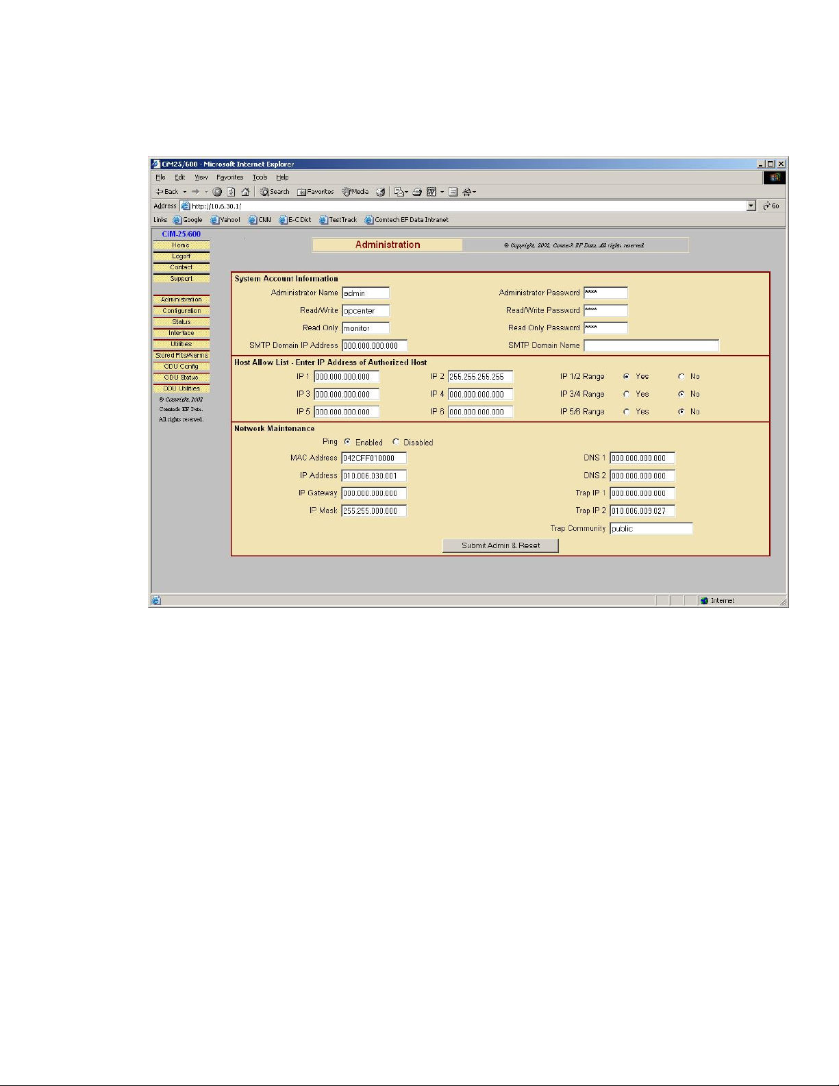
3.3.5 ADMINISTRATION PAGE (COMMON)
The Administration Page is only available to users who have logged in using the
Administrator Name and Password.
3.3.5.1 ADMINISTRATOR NAME AND PASSWORD
The factory defaults for these parameters are admin and 1234 respectively. The Name
field can be any alpha-numeric combination with a minimum length of 4 characters and a
maximum length of 10 characters. The Password field can be any alpha-numeric
combination with a minimum length of 4 characters and a maximum length of 10
characters.
16
Page 37

CiM-25/600 IP Enabled M&C Rev. 3
SNMP Interface CD/CIM25600.IOM
3.3.5.2 READ/WRITE NAME AND PASSWORD
The factory defaults for these parameters are opcenter and 1234 respectively. The Name
field can be any alpha-numeric combination with a minimum length of 4 characters and a
maximum length of 10 characters. The Password field can be any alpha-numeric
combination with a minimum length of 4 characters and a maximum length of 10
characters.
3.3.5.3 READ ONLY NAME AND PASSWORD
The factory defaults for these parameters are monitor and 1234 respectively. The Name
field can be any alpha-numeric combination with a minimum length of 4 characters and a
maximum length of 10 characters. The Password field can be any alpha-numeric
combination with a minimum length of 4 characters and a maximum length of 10
characters.
3.3.5.4 HOST ALLOW LIST
The Host Allow List can be configured as any of the following combinations:
1 to 6 individual IP addresses.
1 to 3 ranges of IP addresses.
A combination of individual and range addresses.
The Administrator simply checks the Range Yes radio button next to the group of two IP
addresses that constitute the beginning and ending of the range.
3.3.5.5 PING ENABLE / DISABLE
The factory defaults for this parameter is Enabled. The radio buttons allow the
Administrator to choose between Enabled and Disabled.
3.3.5.6 CiM-25 IP ADDRESS, GATE WAY AN D MASK
The factory defaults for these parameters are 10.6.30.1, 0.0.0.0, and 255.255.0.0
respectively. The Administrator can change these as required.
3.3.5.7 DNS SERVERS
The Administrator can assign both a primary and secondary DNS server IP address.
17
Page 38

CiM-25/600 IP Enabled M&C Rev. 3
SNMP Interface CD/CIM25600.IOM
3.3.5.8 SMTP DOMAIN NAME AND IP ADDRESS
The Administrator can assign the SMTP Domain Name and Domain IP Address. This is
required if the email feature of the Support Page is to be used.
3.3.5.9 SNMP TRAP IP ADDRESS
The Administrator can assign up to two SNMP Trap IP addresses.
3.3.5.10 MAC ADDRESS
This is a READ ONLY parameter and cannot be changed.
3.3.5.11 SNMP TRAP COMMUNITY
The Administrator can assign a SNMP Trap Community. The factory default for this
parameter is public. The SNMP Trap Community field can be any combination of
characters and a length of 0 - 20 characters.
18
Page 39

CiM-25/600 IP Enabled M&C Rev. 3
SNMP Interface CD/CIM25600.IOM
3.3.6 MODEM CONFIGURATION PAGE (RX/TX)
This page can be viewed by all three levels of user login. However, only a user with
Administrative or Read/Write privileges can submit changes to this page. This page
allows the user to configure the primary Transmit and Receive Parameters of a CDM-600
Modem.
Note: The Tx and Rx interface Type and Frame Module have higher priority than other
parameters, and should be configured before setting other parameters.
19
Page 40

CiM-25/600 IP Enabled M&C Rev. 3
SNMP Interface CD/CIM25600.IOM
3.3.7 STATUS PAGE
This page can be viewed by all three levels of user login. This is a Read Only Page and
has no submit button. This page provides various status information for a CDM-600
Modem.
20
Page 41

CiM-25/600 IP Enabled M&C Rev. 3
SNMP Interface CD/CIM25600.IOM
3.3.8 INTERFACE PARAMETERS PAGE (TX/RX)
This page can be viewed by all three levels of user login. However, only a user with
Administrative or Read/Write privileges can submit changes to this page. This page
allows the user to configure the Transmit and Receive Interface Parameters and Drop &
Insert parameters of a CDM-600 Modem.
21
Page 42
CiM-25/600 IP Enabled M&C Rev. 3
SNMP Interface CD/CIM25600.IOM
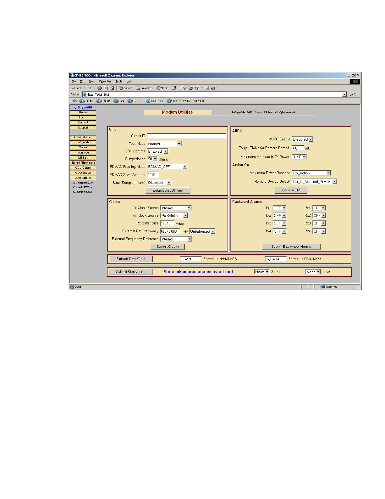
3.3.9 UTILITIES PAGE
This page can be viewed by all three levels of user login. However, only a user with
Administrative or Read/Write privileges can submit changes to this page. This page
allows the user to configure various utility functions on a CDM-600 Modem.
22
Page 43

CiM-25/600 IP Enabled M&C Rev. 3
SNMP Interface CD/CIM25600.IOM
3.3.10 STORED FAULTS/ALARMS
This page can be viewed by all three levels of user login. This is a Read/Write page. This
page allows the user to Read/Clear Events Log, Statistics Log, and configure Alarm
Masks of the CDM-600 Modem.
23
Page 44

CiM-25/600 IP Enabled M&C Rev. 3
SNMP Interface CD/CIM25600.IOM
3.3.11 CSAT-5060 AND KST-2000A/B ODU PAGES
The CiM-25/600 IP Module can function with CSAT ODU firmware version 2.18 or
higher and KST-2000A/B ODU. All ODU pages are accessible only when ODU COMM
on the Utilities-Unit page is set to ENABLED.
Note: The same three menu options on the left side of the screen capture work for both
CSAT and KST ODU. The correct page will be brought out for the correct ODU when
the ODU menu is clicked.
3.3.11.1 CSAT-5060 ODU CONFIGURATION PAGE
This page can be viewed by all three levels of user login. However, only a user with
Administrative or Read/Write privileges can submit changes to this page. The user can
use this page to configure the primary Transmit and Receive Parameters of a CSAT-5060
ODU.
Note:
If redundant ODUs are used, the page can be toggled between the Online and
Offline units by selecting ODU #1 or ODU #2 in the ODU Selection box and clicking
Submit.
24
Page 45

CiM-25/600 IP Enabled M&C Rev. 3
SNMP Interface CD/CIM25600.IOM
3.3.11.2 CSAT-5060 ODU STATUS PAGE
This page can be viewed by all three levels of user login. This is a Read Only Page and
has no submit button for the Status Information. This page provides various status
information for a CSAT-5060 ODU.
Note:
If redundant ODUs are used, the page can be toggled between the Online and
Offline units by selecting ODU #1 or ODU #2 in the ODU Selection box and clicking
Submit.
25
Page 46

CiM-25/600 IP Enabled M&C Rev. 3
SNMP Interface CD/CIM25600.IOM
3.3.11.3 CSAT-5060 ODU UTILITIES PAGE
This page can be viewed by all three levels of user login. However, only a user with
Administrative or Read/Write privileges can submit changes to this page. The user can
perform various utility functions on a CSAT-5060 ODU from this page.
Notes:
If redundant ODUs are used, the page can be toggled between the Online and
Offline units by selecting ODU #1 or ODU #2 in the ODU Selection box and clicking
Submit.
26
Page 47

CiM-25/600 IP Enabled M&C Rev. 3
SNMP Interface CD/CIM25600.IOM
3.3.11.4 KST-2000A/B ODU CONFIGURATION PAGE
This page can be viewed by all three levels of user login. However, only a user with
Administrative or Read/Write privileges can submit changes to this page.
This page is used to configure the unit parameters, and the primary Transmit and Receive
parameters of a KST-2000A/B ODU.
27
Page 48

CiM-25/600 IP Enabled M&C Rev. 3
SNMP Interface CD/CIM25600.IOM
3.3.11.5 KST-2000A/B STATUS PAGE
This page can be viewed by all three levels of user login. However, only a user with
Administrative or Read/Write privileges can submit changes to this page.
This page provides fault status for a KST-2000A/B ODU.
28
Page 49

CiM-25/600 IP Enabled M&C Rev. 3
SNMP Interface CD/CIM25600.IOM
3.3.11.6 KST-2000A/B UTILITIES PAGE
This page can be viewed by all three levels of user login. However, only a user with
Administrative or Read/Write privileges can submit changes to this page.
This page provides the firmware number and version, the assembly number and the serial
number information of different modules of a KST-2000A/B ODU.
29
Page 50

CiM-25/600 IP Enabled M&C Rev. 3
SNMP Interface CD/CIM25600.IOM
3.4 SNMP INTERFACE
CiM-25 supports v2c of the industry standard SNMP (Simple Network Management
Protocol). CiM-25 supports a complete private MIB for the attached equipment as well as
a private MIB for the CiM-25 itself. The SNMP interface supports standard Get and Set
as well as Branch Walking.
The image above is a screen capture of the CiM-25 MIB structure using a common MIB
Browser. The important point here is that all administrative parameters of the CiM-25 are
available in its private MIB.
30
Page 51

CiM-25/600 IP Enabled M&C Rev. 3
SNMP Interface CD/CIM25600.IOM
The image below is a screen capture of the CDM-600 MIB using a common MIB
Browser. The important point here is that all CDM-600 Controllable Parameters and
Status Parameters, Events, and Statistics Log are available in its private CDM-600 MIB.
31
Page 52

CiM-25/600 IP Enabled M&C Rev. 3
SNMP Interface CD/CIM25600.IOM
The image below is a screen capture of the CDM-600 MIB using a common MIB
Browser. The important point here is that all CSAT ODU Controllable Parameters and
Status Parameters, Events, and Statistics Log are available in its private CDM-600 MIB.
32
Page 53

CiM-25/600 IP Enabled M&C Rev. 3
SNMP Interface CD/CIM25600.IOM
The image below is a screen capture of the CDM-600 MIB using a common MIB Browser. The
important point here is that all KST-2000A/B ODU Controllable Parameters and Status
Parameters, Events, and Statistics Logs are available in its private CDM-600 MIB.
33
Page 54

CiM-25/600 IP Enabled M&C Rev. 3
SNMP Interface CD/CIM25600.IOM
3.5 TELNET INTERFACE
The CiM-25 provides a Telnet interface for three primary functions:
System Administration.
Equipment M&C via the standard equipment Remote Control protocol.
Equipment M&C via Comtech EF Data PC based Monitor and Control applications.
The Telnet interface uses two (2) levels of user login, Administrator and Read/Write.
The screen capture below shows the login process.
Once logged into the CiM-25 Telnet interface as the Administrator, the user can access
the built in menu function by typing a ? (question mark). This menu is only available to
the Administrator. The screen capture below shows the functions available via this menu
system. Entering any command without any data parameters will cause the CiM-25 to
respond with a message that provides the proper formatting requirements for the
individual command. Entering any command with a ? (question mark) as the parameter
will cause the CiM-25 to respond with the current Set value. Each command will be
explained in the following section.
34
Page 55

CiM-25/600 IP Enabled M&C Rev. 3
SNMP Interface CD/CIM25600.IOM
3.5.1 TELNET ADMINISTRATIVE FUNCTIONS
3.5.1.1 C
Using the !IP command, the Administrator can change the IP Address, IP Gateway, and
IP Mask. The command protocol is as follows:
Format: !IP <ip> <gateway> <mask>
Example: !IP 10.6.30.2 10.6.30.255 255.255.0.0
Query Format: !IP ?
Response: !IP 10.6.30.2 10.6.30.255 255.255.0.0
Note:
HANGE IP ADDRESS, GATEWAY AND MASK
Changes made via this command do not become active until the user has sent a !EE
command to commit the changes to EEPROM of the CiM-25.
35
Page 56

CiM-25/600 IP Enabled M&C Rev. 3
SNMP Interface CD/CIM25600.IOM
3.5.1.2 CHANGE HOST ALLOW LIST
Using the !HA command, the Administrator can modify the Host Allow List. The
command protocol is as follows:
Format: !HA <address index> <ip_address> <ranged>
Where: address index is 1 to 6, ranged is 0 if No and 1 if yes
Example: !HA 5 10.50.91.200 0
This sets IP address #5 to 10.50.91.200 and indicates addresses #5 & #6 are NOT ranged.
Query Format: !HA ?
Response: IP 1: 000.000.000.000 IP 2: 255.255.255.255 Range = yes
IP 3: 000.000.000.000 IP 4: 000.000.000.000 Range = no
IP 5: 000.000.000.000 IP 6: 000.000.000.000 Range = no
Note:
Changes made via this command do not become active until the user has sent a !EE
command to commit the changes to EEPROM of the CiM-25.
3.5.1.3 CHANGE ADMINISTRATOR NAME
Using the !AD command, the Administrator can change the Administrator login Name.
The command protocol is as follows:
Format: !AD <string>
Where: <string> can be any alphanumeric string of 4 to 10 characters in length
Query Format: !AD ?
Response: !AD <string>
Note:
Changes made via this command do not become active until the user has sent a !EE
command to commit the changes to EEPROM of the CiM-25.
3.5.1.4 CHANGE ADMINISTRATOR PASSWORD
Using the !PW command, the Administrator can change the Administrator login
Password. The command protocol is as follows:
Format: !PW <string>
Where: <string> can be any alphanumeric string of 4 to 10 characters in length
Query Format: !PW ?
Response: !PW <string>
Note:
Changes made via this command do not become active until the user has sent a !EE
command to commit the changes to EEPROM of the CiM-25.
36
Page 57

CiM-25/600 IP Enabled M&C Rev. 3
SNMP Interface CD/CIM25600.IOM
3.5.1.5 CHANGE READ/WRITE NAME
Using the !WN command, the Administrator can change the Read/Write login Name. The
command protocol is as follows:
Format: !WN <string>
Where: <string> can be any alphanumeric string of 4 to 10 characters in length
Query Format: !WN ?
Response: !WN <string>
Note:
Changes made via this command do not become active until the user has sent a !EE
command to commit the changes to EEPROM of the CiM-25.
3.5.1.6 CHANGE READ/WRITE PASSWORD
Using the !WP command, the Administrator can change the Read/Write login Password.
The command protocol is as follows:
Format: !WP <string>
Where: <string> can be any alphanumeric string of 4 to 10 characters in length
Query Format: !WP ?
Response: !WP <string>
Note:
Changes made via this command do not become active until the user has sent a !EE
command to commit the changes to EEPROM of the CiM-25.
3.5.1.7 CHANGE READ ONLY NAME
Using the !RN command, the Administrator can change the Read Only login Name. The
command protocol is as follows:
Format: !RN <string>
Where: <string> can be any alphanumeric string of 4 to 10 characters in length
Query Format: !RN ?
Response: !RN <string>
Note:
Changes made via this command do not become active until the user has sent a !EE
command to commit the changes to EEPROM of the CiM-25.
37
Page 58

CiM-25/600 IP Enabled M&C Rev. 3
SNMP Interface CD/CIM25600.IOM
3.5.1.8 CHANGE READ ONLY PASSWORD
Using the !RP command, the Administrator can change the Read/Only login Password.
The command protocol is as follows:
Format: !RP <string>
Where: <string> can be any alphanumeric string of 4 to 10 characters in length
Query Format: !RP ?
Response: !RP <string>
Note:
Changes made via this command do not become active until the user has sent a !EE
command to commit the changes to EEPROM of the CiM-25.
3.5.1.9 ENABLE OR DISABLE PING
Using the !PG command, the Administrator can either enable or disable PING. The
command protocol is as follows:
Format: !PG <state>
Where: 0 = Disabled, 1 = Enabled
Query Format: !PG ?
Response: !PG <state>
Note:
Changes made via this command do not become active until the user has sent a !EE
command to commit the changes to EEPROM of the CiM-25.
3.5.1.10 COMMIT CHANGES TO EEPROM
Using the !EE command, the Administrator can commit any previously commanded
changes to EEPROM. This will store the new operating parameters and automatically do
a warm reboot of the CiM-25/600. The command protocol is as follows:
Format: !EE
38
Page 59

CiM-25/600 IP Enabled M&C Rev. 3
SNMP Interface CD/CIM25600.IOM
3.5.1.11 CHANGE PRIMARY/SECONDARY DNS IP ADDRESSES
Using the !DN command, the Administrator can set the primary and secondary DNS IP
Addresses. The command protocol is as follows:
Format: !DN <primary DNS IP Address> <secondary DNS IP Address>
Response: Command Successful
Query Format: !DN ?
Response: !DN <primary DNS IP Address> <secondary DNS IP Address>
Note:
Changes made via this command do not become active until the user has sent a !EE
command to commit the changes to EEPROM of the CiM-25.
3.5.1.12 CHANGE SMTP DOMAIN NAME
Using the !SN command, the Administrator can set the SMTP domain name. The
command protocol is as follows:
Format: !SN <string>
Response: Command Successful
Where: <string> can be any alphanumeric string with a length of 1 to 100
characters.
Note:
disabled in the <string> field disables SMTP.
Query Format: !SN ?
Response: !SN <string>
Note:
Changes made via this command do not become active until the user has sent a !EE
command to commit the changes to EEPROM of the CiM-25.
3.5.1.13 CHANGE SMTP DOMAIN IP ADDRESS
Using the !SD command, the Administrator can set the SMTP Domain IP Address. The
command protocol is as follows:
Format: !SD <ip_address>
Response: Command Successful
Note:
An IP Address of 0.0.0.0 disables SMTP.
Query Format: !SD ?
Response: !SD <ip_address>
Note:
Changes made via this command do not become active until the user has sent a !EE
command to commit the changes to EEPROM of the CiM-25.
39
Page 60

CiM-25/600 IP Enabled M&C Rev. 3
SNMP Interface CD/CIM25600.IOM
3.5.1.14 CHANGE HTTP PORT
Using the !PT command, the Administrator can set the HTTP Port. The command
protocol is as follows:
Format: !PT <value>
Response: Command Successful
Where <value> can be any number in the range of 0 to 65535
Query Format: !PT ?
Response: !PT <value>
Notes:
1. The default port is set to 80.
2. Changes made via this command do not become active until the user has sent
a !EE command to commit the changes to EEPROM of the CiM-25.
3.5.1.15 CHANGE SNMP TRAP ADDRESS
Using the !TP command, the Administrator can set the SNMP Trap Addresses. The
command protocol is as follows:
Format: !TP <ip_address1> <ip_address2>
Response: Command Successful
Note:
An IP Address of 0.0.0.0 disables the trap
Query Format: !TP ?
Response: !TP <ip_address1> <ip_address2>
Note:
Changes made via this command do not become active until the user has sent a !EE
command to commit the changes to EEPROM of the CiM-25.
3.5.1.16 CHANGE SNMP TRAP COMMUNITY
Using the !TC command, the Administrator can set the SNMP Trap Community. The
command protocol is as follows:
Format: !TC <string>
Response: Command Successful
where <string> can be 0 - 20 characters
Query Format: !TC ?
Response: !TC <string>
Note:
Changes made via this command do not become active until the user has sent a !EE
command to commit the changes to EEPROM of the CiM-25.
40
Page 61

CiM-25/600 IP Enabled M&C Rev. 3
SNMP Interface CD/CIM25600.IOM
3.5.2 USING TELNET WITH EQUIPMENT REMOTE CONTROL PROTOCOL
The CiM-25/600 Telnet interface will accept any command defined in the particular
interfacing equipment Remote Control Specification. See the equipment Operation
Manual for details regarding the available commands and the message protocol. The
screen capture below shows an example of how to directly use the equipment’s Remote
Control Protocol to communicate to the equipment via the Telnet interface.
41
Page 62

CiM-25/600 IP Enabled M&C Rev. 3
SNMP Interface CD/CIM25600.IOM
3.6 MAINTENANCE INTERFACE
The default network configuration settings are:
IP: 10.6.30.1
Admin Name: admin
Admin Password: 1234
The CiM-25 has been designed to allow a user to reset the unit back to the factory default
settings, change the IP Address, and verify the software version. Use the following
procedure to make these changes.
Perform the following steps:
Disconnect the CiM-25 from both the interfacing equipment and the Ethernet Network.
1
Connect the CiM-25 to the serial port of a PC using a cable defined below (null cable):
2
CiM-25 pin 2 to PC pin 3
CiM-25 pin 3 to PC pin 2
CiM-25 pin 5 to PC pin 5
To Computer
(Usually Female)
To CiM-25 Device
(M/F Depending on Unit)
2
3
DB9
5
Figure 1. Null Cable Diagram
Power the CiM-25 using the Power Jack connector and an external 5 Vdc power supply.
3
Using a Serial Communication application such as Terminal, ProComm, etc., configure the
4
PC’s serial port to:
Baud: 19200
Data rate: 8-N-1
2
DB9
3
5
Use the procedures in following sections to:
Reset to factory network defaults.
Change network IP Address.
Verify software version.
Change MAC Address.
Change Serial Number.
42
Page 63

CiM-25/600 IP Enabled M&C Rev. 3
SNMP Interface CD/CIM25600.IOM
3.6.1 RESETTING TO FACTORY DEFAULTS
Enter the following command:
1
Command: <0/RST=’cr’
Response: >0/RST=
3.6.2 CHANGING NETWORK IP ADDRESS
Perform the following steps.
Enter the following command:
1
Command: <0/IPA=xxx.xxx.xxx.xxx/yy’cr’
Where x is the IP Address and y is the subnet mask.
Response: >0/IPA=
Example: <0/IPA=192.168.001.002/16’cr’
16 would be a subnet mask of 255.255.0.0
To query the IP address enter: <0/IPA?’cr’
2
3.6.3 VERIFYING SOFTWARE VERSION
Perform the following:
Enter the following command:
1
Command: <0/SWR?’cr’
Response: >0/SWR= 1.0.1’cr’
3.6.4 CHANGING MAC ADDRESS
Perform the following:
Enter the following command:
1
Command: <0/MAC=xxxxxxxxx’cr’
Where x is the MAC Address as shown on the label of the CiM-25.
Response: >0/MAC=
2
Example: >0/MAC=006B0000000A’cr’
To query the MAC Address enter: >0/MAC?’cr’
1. The MAC Address is unique to this unit. Change only under factory
direction or if it does not match the label.
IMPORTANT
2. Changing the MAC Address to anything other than factory default may
result in erratic operation.
43
Page 64

CiM-25/600 IP Enabled M&C Rev. 3
SNMP Interface CD/CIM25600.IOM
3.6.5 CHANGING SERIAL NUMBER
Perform the following:
Enter the following command:
1
Command: <0/SNM=xxxxxxxxx’cr’
Where x is the Serial Number as shown on the label of the CiM-25.
Response: >0/SNM=
2
IMPORTANT
Example: >0/SNM=022080125A’cr’
To query the Serial Number enter: >0/SNM?’cr’
The Serial Number is unique to this unit. Change only under factory direction or
if it does not match the label.
44
Page 65

CiM-25/600 IP Enabled M&C Rev. 3
SNMP Interface CD/CIM25600.IOM
Appendix A.
CiM-25/600 SNMP Interface
A.1 SNMP INTERFACE
The Simple Network Management Protocol (SNMP) is an application-layer protocol
designed to facilitate the exchange of management information between network devices.
The CiM-25/600 SNMP agent supports SNMP v2c.
A.2 MIB-II
The CiM-25/600 agent implements RFC 1213, Management Information Base for
Network Management of TCP/IP-based Internets. This is known as “MIB-II support.”
Please refer to RFC 1213 for this definition.
A.3 PRIVATE MIB IMPLEMENTATIONS
The agent also implements two private MIBs for the CiM-25/600. The CiM IP Controller
MIB (CiM-25) holds all the security, feature selection, and IP related parameters, and the
CDM-600 modem MIB contains all the modem specific parameters.
45
Page 66

CiM-25/600 IP Enabled M&C Rev. 3
SNMP Interface CD/CIM25600.IOM
A.4 CIM-25 MIB TREE
1 - 1 --- iso
2 - 1.3 --- org
3 - 1.3.6 --- dod
4 - 1.3.6.1 --- internet
5 - 1.3.6.1.4 --- private
6 - 1.3.6.1.4.1 --- enterprises
7 - 1.3.6.1.4.1.6247 --- comtech
8 - 1.3.6.1.4.1.6247.3 --- cim25
9 - 1.3.6.1.4.1.6247.3.1 --- cim25Objects
10 - 1.3.6.1.4.1.6247.3.1.1 --- ipAddress1 (IpAddress)
11 - 1.3.6.1.4.1.6247.3.1.2 --- ipAddress2 (IpAddress)
12 - 1.3.6.1.4.1.6247.3.1.3 --- ipAddress12Range (INTEGER)
13 - 1.3.6.1.4.1.6247.3.1.4 --- ipAddress3 (IpAddress)
14 - 1.3.6.1.4.1.6247.3.1.5 --- ipAddress4 (IpAddress)
15 - 1.3.6.1.4.1.6247.3.1.6 --- ipAddress34Range (INTEGER)
16 - 1.3.6.1.4.1.6247.3.1.7 --- ipAddress5 (IpAddress)
17 - 1.3.6.1.4.1.6247.3.1.8 --- ipAddress6 (IpAddress)
18 - 1.3.6.1.4.1.6247.3.1.9 --- ipAddress56Range (INTEGER)
19 - 1.3.6.1.4.1.6247.3.1.10 --- dnsIpAddressPrimary (IpAddress)
20 - 1.3.6.1.4.1.6247.3.1.11 --- dnsIpAddressSecondary (IpAddress)
21 - 1.3.6.1.4.1.6247.3.1.12 --- cim25IpAddress (IpAddress)
46
Page 67

CiM-25/600 IP Enabled M&C Rev. 3
SNMP Interface CD/CIM25600.IOM
22 - 1.3.6.1.4.1.6247.3.1.13 --- cim25IpGateway (IpAddress)
23 - 1.3.6.1.4.1.6247.3.1.14 --- cim25IpMask (IpAddress)
24 - 1.3.6.1.4.1.6247.3.1.15 --- readonlyPassword (OCTET STRING)
25 - 1.3.6.1.4.1.6247.3.1.16 --- readwritePassword (OCTET STRING)
26 - 1.3.6.1.4.1.6247.3.1.17 --- administratorPassword (OCTET STRING)
27 - 1.3.6.1.4.1.6247.3.1.18 --- trapIpAddress1 (IpAddress)
28 - 1.3.6.1.4.1.6247.3.1.19 --- trapIpAddress2 (IpAddress)
29 - 1.3.6.1.4.1.6247.3.1.20 --- trapCommunity (OCTET STRING)
30 - 1.3.6.1.4.1.6247.3.1.21 --- administratorName (OCTET STRING)
31 - 1.3.6.1.4.1.6247.3.1.22 --- readonlyName (OCTET STRING)
32 - 1.3.6.1.4.1.6247.3.1.23 --- readwriteName (OCTET STRING)
33 - 1.3.6.1.4.1.6247.3.1.24 --- macAddress (OCTET STRING)
34 - 1.3.6.1.4.1.6247.3.1.25 --- submitconfig (INTEGER)
47
Page 68

CiM-25/600 IP Enabled M&C Rev. 3
SNMP Interface CD/CIM25600.IOM
A.5 CIM-25 MIB
A.5.1 ISO
Name
OID
Full path
Module
Child
Type
A.5.2 ORG
Name
OID
Full path
Module
Parent
Child
Type
A.5.3 DOD
Name
OID
Full path
Module
Parent
Child
Type
iso
1
iso(1)
SNMPv2-SMI
org
OBJECT-IDENTIFIER
org
1.3
iso(1).org(3)
SNMPv2-SMI
iso
dod
OBJECT-IDENTIFIER
dod
1.3.6
iso(1).org(3).dod(6)
SNMPv2-SMI
org
internet
OBJECT-IDENTIFIER
A.5.4 INTERNET
Name
OID
Full path
Module
Parent
Child
Type
A.5.5 PRIVATE
Name
OID
Full path
Module
Parent
Child
Type
internet
1.3.6.1
iso(1).org(3).dod(6).internet(1)
SNMPv2-SMI
dod
private
OBJECT-IDENTIFIER
private
1.3.6.1.4
iso(1).org(3).dod(6).internet(1).private(4)
CIM25
internet
enterprises
OBJECT-IDENTIFIER
48
Page 69

CiM-25/600 IP Enabled M&C Rev. 3
SNMP Interface CD/CIM25600.IOM
A.5.6 ENTERPRISES
Name
OID
Full path
Module
Parent
Child
Type
A.5.7 COMTECH
Name
OID
Full path
Module
Parent
Child
Type
A.5.8 CIM25
Name
OID
Full path
Module
Parent
Child
Type
enterprises
1.3.6.1.4.1
iso(1).org(3).dod(6).internet(1).private(4).enterprises(1)
CIM25
private
comtech
OBJECT-IDENTIFIER
comtech
1.3.6.1.4.1.6247
iso(1).org(3).dod(6).internet(1).private(4).enterprises(1).comtech(6247)
CIM25
enterprises
cim25
OBJECT-IDENTIFIER
cim25
1.3.6.1.4.1.6247.3
iso(1).org(3).dod(6).internet(1).private(4).enterprises(1).comtech(6247)
.cim25(3)
CIM25
comtech
cim25Objects
OBJECT-IDENTIFIER
A.5.9 CIM25OBJECTS
Name
OID
Full path
Module
Parent
Child
Type
cim25Objects
1.3.6.1.4.1.6247.3.1
iso(1).org(3).dod(6).internet(1).private(4).enterprises(1).comtech(6247)
.cim25(3).cim25Objects(1)
CIM25
cim25
ipAddress1
OBJECT-IDENTIFIER
49
Page 70

CiM-25/600 IP Enabled M&C Rev. 3
SNMP Interface CD/CIM25600.IOM
A.5.10 IPADDRESS1
Name
OID
Full path
Module
Parent
Next sibling
Type
Numerical syntax
Base syntax
Composed syntax
Status
Max-access
Description
A.5.11 IPADDRESS2
Name
OID
Full path
Module
Parent
Prev sibling
Next sibling
Type
Numerical syntax
Base syntax
Composed syntax
Status
Max-access
Description
ipAddress1
1.3.6.1.4.1.6247.3.1.1
iso(1).org(3).dod(6).internet(1).private(4).enterprises(1).comtech(6247)
.cim25(3).cim25Objects(1).ipAddress1(1)
CIM25
cim25Objects
ipAddress2
OBJECT-TYPE
SNMP_SYNTAX_IPADDR
IpAddress
IpAddress
current
read-write
IP Address 1 or IP Address 1 Start Range.
ipAddress2
1.3.6.1.4.1.6247.3.1.2
iso(1).org(3).dod(6).internet(1).private(4).enterprises(1).comtech(6247)
.cim25(3).cim25Objects(1).ipAddress2(2)
CIM25
cim25Objects
ipAddress1
ipAddress12Range
OBJECT-TYPE
SNMP_SYNTAX_IPADDR
IpAddress
IpAddress
current
read-write
IP Address 2 or IP Address 1 End Range.
50
Page 71

CiM-25/600 IP Enabled M&C Rev. 3
SNMP Interface CD/CIM25600.IOM
A.5.12 IPADDRESS12RANGE
Name
OID
Full path
Module
Parent
Prev sibling
Next sibling
Type
Numerical syntax
Base syntax
Composed syntax
Status
Max-access
Value list
1
2
Description
A.5.13 IPADDRESS3
Name
OID
Full path
Module
Parent
Prev sibling
Next sibling
Type
Numerical syntax
Base syntax
Composed syntax
Status
Max-access
Description
ipAddress12Range
1.3.6.1.4.1.6247.3.1.3
iso(1).org(3).dod(6).internet(1).private(4).enterprises(1).comtech(6247)
.cim25(3).cim25Objects(1).ipAddress12Range(3)
CIM25
cim25Objects
ipAddress2
ipAddress3
OBJECT-TYPE
SNMP_SYNTAX_INT
INTEGER
INTEGER
current
read-write
no(0)
yes(1)
Range or Individual for IP Address 1 and 2.
ipAddress3
1.3.6.1.4.1.6247.3.1.4
iso(1).org(3).dod(6).internet(1).private(4).enterprises(1).comtech(6247)
.cim25(3).cim25Objects(1).ipAddress3(4)
CIM25
cim25Objects
ipAddress12Range
ipAddress4
OBJECT-TYPE
SNMP_SYNTAX_IPADDR
IpAddress
IpAddress
current
read-write
IP Address 3 or IP Address 2 Start Range.
51
Page 72

CiM-25/600 IP Enabled M&C Rev. 3
SNMP Interface CD/CIM25600.IOM
A.5.14 IPADDRESS4
Name
OID
Full path
Module
Parent
Prev sibling
Next sibling
Type
Numerical syntax
Base syntax
Composed syntax
Status
Max-access
Description
A.5.15 IPADDRESS34RANGE
Name
OID
Full path
Module
Parent
Prev sibling
Next sibling
Type
Numerical syntax
Base syntax
Composed syntax
Status
Max-access
Value list
1
2
Description
ipAddress4
1.3.6.1.4.1.6247.3.1.5
iso(1).org(3).dod(6).internet(1).private(4).enterprises(1).comtech(6247)
.cim25(3).cim25Objects(1).ipAddress4(5)
CIM25
cim25Objects
ipAddress3
ipAddress34Range
OBJECT-TYPE
SNMP_SYNTAX_IPADDR
IpAddress
IpAddress
current
read-write
IP Address 4 or IP Address 2 End Range.
ipAddress34Range
1.3.6.1.4.1.6247.3.1.6
iso(1).org(3).dod(6).internet(1).private(4).enterprises(1).comtech(6247)
.cim25(3).cim25Objects(1).ipAddress34Range(6)
CIM25
cim25Objects
ipAddress4
ipAddress5
OBJECT-TYPE
SNMP_SYNTAX_INT
INTEGER
INTEGER
current
read-write
no(0)
yes(1)
Range or Individual for IP Address 3 and 4.
52
Page 73

CiM-25/600 IP Enabled M&C Rev. 3
SNMP Interface CD/CIM25600.IOM
A.5.16 IPADDRESS5
Name
OID
Full path
Module
Parent
Prev sibling
Next sibling
Type
Numerical syntax
Base syntax
Composed syntax
Status
Max-access
Description
A.5.17 IPADDRESS6
Name
OID
Full path
Module
Parent
Prev sibling
Next sibling
Type
Numerical syntax
Base syntax
Composed syntax
Status
Max-access
Description
ipAddress5
1.3.6.1.4.1.6247.3.1.7
iso(1).org(3).dod(6).internet(1).private(4).enterprises(1).comtech(6247)
.cim25(3).cim25Objects(1).ipAddress5(7)
CIM25
cim25Objects
ipAddress34Range
ipAddress6
OBJECT-TYPE
SNMP_SYNTAX_IPADDR
IpAddress
IpAddress
current
read-write
IP Address 5 or IP Address 3 Start Range.
ipAddress6
1.3.6.1.4.1.6247.3.1.8
iso(1).org(3).dod(6).internet(1).private(4).enterprises(1).comtech(6247)
.cim25(3).cim25Objects(1).ipAddress6(8)
CIM25
cim25Objects
ipAddress5
ipAddress56Range
OBJECT-TYPE
SNMP_SYNTAX_IPADDR
IpAddress
IpAddress
current
read-write
IP Address 6 or IP Address 3 End Range.
53
Page 74

CiM-25/600 IP Enabled M&C Rev. 3
SNMP Interface CD/CIM25600.IOM
A.5.18 IPADDRESS56RANGE
Name
OID
Full path
Module
Parent
Prev sibling
Next sibling
Type
Numerical syntax
Base syntax
Composed syntax
Status
Max-access
Value list
1
2
Description
ipAddress56Range
1.3.6.1.4.1.6247.3.1.9
iso(1).org(3).dod(6).internet(1).private(4).enterprises(1).comtech(6247)
.cim25(3).cim25Objects(1).ipAddress56Range(9)
CIM25
cim25Objects
ipAddress6
dnsIpAddressPrimary
OBJECT-TYPE
SNMP_SYNTAX_INT
INTEGER
INTEGER
current
read-write
no(0)
yes(1)
Range or Individual for IP Address 5 and 6.
A.5.19 DNSIPADDRESSPRIMARY
Name
OID
Full path
Module
Parent
Prev sibling
Next sibling
Type
Numerical syntax
Base syntax
Composed syntax
Status
Max-access
Description
dnsIpAddressPrimary
1.3.6.1.4.1.6247.3.1.10
iso(1).org(3).dod(6).internet(1).private(4).enterprises(1).comtech(6247)
.cim25(3).cim25Objects(1).dnsIpAddressPrimary(10)
CIM25
cim25Objects
ipAddress56Range
dnsIpAddressSecondary
OBJECT-TYPE
SNMP_SYNTAX_IPADDR
IpAddress
IpAddress
current
read-write
Primary DNS IP Address.
54
Page 75

CiM-25/600 IP Enabled M&C Rev. 3
SNMP Interface CD/CIM25600.IOM
A.5.20 DNSIPADDRESSSECONDARY
Name
OID
Full path
Module
Parent
Prev sibling
Next sibling
Type
Numerical syntax
Base syntax
Composed syntax
Status
Max-access
Description
A.5.21 CIM25IPADDRESS
Name
OID
Full path
Module
Parent
Prev sibling
Next sibling
Type
Numerical syntax
Base syntax
Composed syntax
Status
Max-access
Description
dnsIpAddressSecondary
1.3.6.1.4.1.6247.3.1.11
iso(1).org(3).dod(6).internet(1).private(4).enterprises(1).comtech(6247)
.cim25(3).cim25Objects(1).dnsIpAddressSecondary(11)
CIM25
cim25Objects
dnsIpAddressPrimary
cim25IpAddress
OBJECT-TYPE
SNMP_SYNTAX_IPADDR
IpAddress
IpAddress
current
read-write
Secondary DNS IP Address.
cim25IpAddress
1.3.6.1.4.1.6247.3.1.12
iso(1).org(3).dod(6).internet(1).private(4).enterprises(1).comtech(6247)
.cim25(3).cim25Objects(1).cim25IpAddress(12)
CIM25
cim25Objects
dnsIpAddressSecondary
cim25IpGateway
OBJECT-TYPE
SNMP_SYNTAX_IPADDR
IpAddress
IpAddress
current
read-write
CiM 25 IP Address.
A.5.22 CIM25IPGATEWAY
Name
OID
Full path
Module
Parent
Prev sibling
Next sibling
Type
Numerical syntax
Base syntax
Composed syntax
Status
Max-access
Description
cim25IpGateway
1.3.6.1.4.1.6247.3.1.13
iso(1).org(3).dod(6).internet(1).private(4).enterprises(1).comtech(6247)
.cim25(3).cim25Objects(1).cim25IpGateway(13)
CIM25
cim25Objects
cim25IpAddress
cim25IpMask
OBJECT-TYPE
SNMP_SYNTAX_IPADDR
IpAddress
IpAddress
current
read-write
CiM 25 IP Gateway
55
Page 76

CiM-25/600 IP Enabled M&C Rev. 3
SNMP Interface CD/CIM25600.IOM
A.5.23 CIM25IPMASK
Name
OID
Full path
Module
Parent
Prev sibling
Next sibling
Type
Numerical syntax
Base syntax
Composed syntax
Status
Max-access
Description
A.5.24 READONLYPASSWORD
Name
OID
Full path
Module
Parent
Prev sibling
Next sibling
Type
Numerical syntax
Base syntax
Composed syntax
Status
Max-access
Size list
1
Description
cim25IpMask
1.3.6.1.4.1.6247.3.1.14
iso(1).org(3).dod(6).internet(1).private(4).enterprises(1).comtech(6247)
.cim25(3).cim25Objects(1).cim25IpMask(14)
CIM25
cim25Objects
cim25IpGateway
readonlyPassword
OBJECT-TYPE
SNMP_SYNTAX_IPADDR
IpAddress
IpAddress
current
read-write
CiM25 IP Mask.
readonlyPassword
1.3.6.1.4.1.6247.3.1.15
iso(1).org(3).dod(6).internet(1).private(4).enterprises(1).comtech(6247)
.cim25(3).cim25Objects(1).readonlyPassword(15)
CIM25
cim25Objects
cim25IpMask
readwritePassword
OBJECT-TYPE
SNMP_SYNTAX_OCTETS
OCTET STRING
OCTET STRING
current
read-write
4..10
Read-Only Password.
56
Page 77

CiM-25/600 IP Enabled M&C Rev. 3
SNMP Interface CD/CIM25600.IOM
A.5.25 READWRITEPASSWORD
Name
OID
Full path
Module
Parent
Prev sibling
Next sibling
Type
Numerical syntax
Base syntax
Composed syntax
Status
Max-access
Size list
1
Description
readwritePassword
1.3.6.1.4.1.6247.3.1.16
iso(1).org(3).dod(6).internet(1).private(4).enterprises(1).comtech(6247)
.cim25(3).cim25Objects(1).readwritePassword(16)
CIM25
cim25Objects
readonlyPassword
administratorPassword
OBJECT-TYPE
SNMP_SYNTAX_OCTETS
OCTET STRING
OCTET STRING
current
read-write
4..10
Read-Write Password.
A.5.26 ADMINISTRATORPASSWORD
Name
OID
Full path
Module
Parent
Prev sibling
Next sibling
Type
Numerical syntax
Base syntax
Composed syntax
Status
Max-access
Size list
1
Description
administratorPassword
1.3.6.1.4.1.6247.3.1.17
iso(1).org(3).dod(6).internet(1).private(4).enterprises(1).comtech(6247)
.cim25(3).cim25Objects(1).administratorPassword(17)
CIM25
cim25Objects
readwritePassword
trapIpAddress
OBJECT-TYPE
SNMP_SYNTAX_OCTETS
OCTET STRING
OCTET STRING
current
read-write
4..10
Administrator Password.
57
Page 78

CiM-25/600 IP Enabled M&C Rev. 3
SNMP Interface CD/CIM25600.IOM
A.5.27 TRAPIPADDRESS1
Name
OID
Full path
Module
Parent
Prev sibling
Next sibling
Type
Numerical syntax
Base syntax
Composed syntax
Status
Max-access
Description
A.5.28 TRAPIPADDRESS 2
Name
OID
Full path
Module
Parent
Prev sibling
Next sibling
Type
Numerical syntax
Base syntax
Composed syntax
Status
Max-access
Description
trapIpAddress1
1.3.6.1.4.1.6247.3.1.18
iso(1).org(3).dod(6).internet(1).private(4).enterprises(1).comtech(6247)
.cim25(3).cim25Objects(1).trapIpAddress1(18)
CIM25
cim25Objects
administratorPassword
trapIpAddress2
OBJECT-TYPE
SNMP_SYNTAX_IPADDR
IpAddress
IpAddress
current
read-write
Trap IP Address 1.
trapIpAddress2
1.3.6.1.4.1.6247.3.1.19
iso(1).org(3).dod(6).internet(1).private(4).enterprises(1).comtech(6247)
.cim25(3).cim25Objects(1).trapIpAddress2(19)
CIM25
cim25Objects
trapIpAddress1
trapCommunity
OBJECT-TYPE
SNMP_SYNTAX_IPADDR
IpAddress
IpAddress
current
read-write
Trap IP Address 2.
A.5.29 TRAPCOMMUNITY
Name
OID
Full path
Module
Parent
Prev sibling
Next sibling
Type
Numerical syntax
Base syntax
Composed syntax
Status
Max-access
Size list
1 0..20
Description Trap Community.
trapCommunity
1.3.6.1.4.1.6247.3.1.19
iso(1).org(3).dod(6).internet(1).private(4).enterprises(1).comtech(6247)
.cim25(3).cim25Objects(1).trapCommunity(19)
CIM25
cim25Objects
trapIpAddress
administratorName
OBJECT-TYPE
SNMP_SYNTAX_OCTETS
OCTET STRING
OCTET STRING
current
read-write
58
Page 79

CiM-25/600 IP Enabled M&C Rev. 3
SNMP Interface CD/CIM25600.IOM
A.5.30 ADMINISTRATORNAME
Name
OID
Full path
Module
Parent
Prev sibling
Next sibling
Type
Numerical syntax
Base syntax
Composed syntax
Status
Max-access
Size list
1
Description
A.5.31 READONLYNAME
Name
OID
Full path
Module
Parent
Prev sibling
Next sibling
Type
Numerical syntax
Base syntax
Composed syntax
Status
Max-access
Size list
1
Description
administratorName
1.3.6.1.4.1.6247.3.1.20
iso(1).org(3).dod(6).internet(1).private(4).enterprises(1).comtech(6247)
.cim25(3).cim25Objects(1).administratorName(20)
CIM25
cim25Objects
trapCommunity
readonlyName
OBJECT-TYPE
SNMP_SYNTAX_OCTETS
OCTET STRING
OCTET STRING
current
read-write
5..10
Administrator User Name.
readonlyName
1.3.6.1.4.1.6247.3.1.21
iso(1).org(3).dod(6).internet(1).private(4).enterprises(1).comtech(6247)
.cim25(3).cim25Objects(1).readonlyName(21)
CIM25
cim25Objects
administratorName
readwriteName
OBJECT-TYPE
SNMP_SYNTAX_OCTETS
OCTET STRING
OCTET STRING
current
read-write
5..10
Read-Only User Name.
59
Page 80

CiM-25/600 IP Enabled M&C Rev. 3
SNMP Interface CD/CIM25600.IOM
A.5.32 READWRITENAME
Name
OID
Full path
Module
Parent
Prev sibling
Next sibling
Type
Numerical syntax
Base syntax
Composed syntax
Status
Max-access
Size list
1
Description
A.5.33 MACADDRESS
Name
OID
Full path
Module
Parent
Prev sibling
Next sibling
Type
Numerical syntax
Base syntax
Composed syntax
Status
Max-access
Size list
1
Description
readwriteName
1.3.6.1.4.1.6247.3.1.22
iso(1).org(3).dod(6).internet(1).private(4).enterprises(1).comtech(6247)
.cim25(3).cim25Objects(1).readwriteName(22)
CIM25
cim25Objects
readonlyName
macAddress
OBJECT-TYPE
SNMP_SYNTAX_OCTETS
OCTET STRING
OCTET STRING
current
read-write
5..10
Read-Write User Name.
macAddress
1.3.6.1.4.1.6247.3.1.23
iso(1).org(3).dod(6).internet(1).private(4).enterprises(1).comtech(6247)
.cim25(3).cim25Objects(1).macAddress(23)
CIM25
cim25Objects
readwriteName
submitconfig
OBJECT-TYPE
SNMP_SYNTAX_OCTETS
OCTET STRING
OCTET STRING
current
read-only
12
MAC Address.
60
Page 81

CiM-25/600 IP Enabled M&C Rev. 3
SNMP Interface CD/CIM25600.IOM
A.5.34 SUBMITCONFIG
Name
OID
Full path
Module
Parent
Prev sibling
Type
Numerical syntax
Base syntax
Composed syntax
Status
Max-access
Value list
1
Description
submitconfig
1.3.6.1.4.1.6247.3.1.24
iso(1).org(3).dod(6).internet(1).private(4).enterprises(1).comtech(6247)
.cim25(3).cim25Objects(1).submitconfig(24)
CIM25
cim25Objects
macAddress
OBJECT-TYPE
SNMP_SYNTAX_INT
INTEGER
INTEGER
current
read-write
submit(1)
Submit changes in CiM 25 Configuration
61
Page 82

CiM-25/600 IP Enabled M&C Rev. 3
SNMP Interface CD/CIM25600.IOM
A.6 CDM-600 MIB TREE:
1 - 1 --- iso
2 - 1.3 --- org
3 - 1.3.6 --- dod
4 - 1.3.6.1 --- internet
5 - 1.3.6.1.4 --- private
6 - 1.3.6.1.4.1 --- enterprises
7 - 1.3.6.1.4.1.6247 --- comtech
8 - 1.3.6.1.4.1.6247.18 --- cdm600
9 - 1.3.6.1.4.1.6247.18.1 --- cdm600Objects
10 - 1.3.6.1.4.1.6247.18.1.1 --- systemInfo
11 - 1.3.6.1.4.1.6247.18.1.1.1 --- equipmentID (OCTET STRING)
12 - 1.3.6.1.4.1.6247.18.1.1.2 --- unitSerialNumber (OCTET STRING)
13 - 1.3.6.1.4.1.6247.18.1.1.3 --- softwareRevision (OCTET STRING)
14 - 1.3.6.1.4.1.6247.18.1.1.4 --- deviceTime (OCTET STRING)
15 - 1.3.6.1.4.1.6247.18.1.1.5 --- deviceDate (OCTET STRING)
16 - 1.3.6.1.4.1.6247.18.1.1.6 --- circuitID (OCTET STRING)
17 - 1.3.6.1.4.1.6247.18.1.1.7 --- localRemoteState (INTEGER)
18 - 1.3.6.1.4.1.6247.18.1.1.8 --- deviceTemperature (INTEGER)
19 - 1.3.6.1.4.1.6247.18.1.2 --- txParameters
20 - 1.3.6.1.4.1.6247.18.1.2.1 --- txFrequency (INTEGER)
21 - 1.3.6.1.4.1.6247.18.1.2.2 --- txDataRate (INTEGER)
22 - 1.3.6.1.4.1.6247.18.1.2.3 --- txModType (INTEGER)
62
Page 83

CiM-25/600 IP Enabled M&C Rev. 3
SNMP Interface CD/CIM25600.IOM
23 - 1.3.6.1.4.1.6247.18.1.2.4 --- txFECType (INTEGER)
24 - 1.3.6.1.4.1.6247.18.1.2.5 --- txFECCodeRate (INTEGER)
25 - 1.3.6.1.4.1.6247.18.1.2.6 --- txSpecInv (INTEGER)
26 - 1.3.6.1.4.1.6247.18.1.2.7 --- txScrambler (INTEGER)
27 - 1.3.6.1.4.1.6247.18.1.2.8 --- txRSEncoding (INTEGER)
28 - 1.3.6.1.4.1.6247.18.1.2.9 --- txPowerLevel (INTEGER)
29 - 1.3.6.1.4.1.6247.18.1.2.10 --- txCarrierState (INTEGER)
30 - 1.3.6.1.4.1.6247.18.1.2.11 --- txDataInv (INTEGER)
31 - 1.3.6.1.4.1.6247.18.1.3 --- rxParameters
32 - 1.3.6.1.4.1.6247.18.1.3.1 --- rxFrequency (INTEGER)
33 - 1.3.6.1.4.1.6247.18.1.3.2 --- rxDataRate (INTEGER)
34 - 1.3.6.1.4.1.6247.18.1.3.3 --- rxDemodType (INTEGER)
35 - 1.3.6.1.4.1.6247.18.1.3.4 --- rxFECType (INTEGER)
36 - 1.3.6.1.4.1.6247.18.1.3.5 --- rxFECCodeRate (INTEGER)
37 - 1.3.6.1.4.1.6247.18.1.3.6 --- rxSpecInv (INTEGER)
38 - 1.3.6.1.4.1.6247.18.1.3.7 --- rxDescrambler (INTEGER)
39 - 1.3.6.1.4.1.6247.18.1.3.8 --- rxRSDecoding (INTEGER)
40 - 1.3.6.1.4.1.6247.18.1.3.9 --- rxDataInv (INTEGER)
41 - 1.3.6.1.4.1.6247.18.1.3.10 --- rxAcqSweepRange (INTEGER)
42 - 1.3.6.1.4.1.6247.18.1.3.11 --- rxEbnoAlarmPoint (INTEGER)
43 - 1.3.6.1.4.1.6247.18.1.4 --- interfaceParameters
44 - 1.3.6.1.4.1.6247.18.1.4.1 --- ifImpedance (INTEGER)
45 - 1.3.6.1.4.1.6247.18.1.4.2 --- txInterfaceType (INTEGER)
46 - 1.3.6.1.4.1.6247.18.1.4.3 --- rxInterfaceType (INTEGER)
47 - 1.3.6.1.4.1.6247.18.1.4.4 --- txFramingMode (INTEGER)
63
Page 84

CiM-25/600 IP Enabled M&C Rev. 3
SNMP Interface CD/CIM25600.IOM
48 - 1.3.6.1.4.1.6247.18.1.4.5 --- rxFramingMode (INTEGER)
49 - 1.3.6.1.4.1.6247.18.1.4.6 --- txClockSource (INTEGER)
50 - 1.3.6.1.4.1.6247.18.1.4.7 --- rxClockSource (INTEGER)
51 - 1.3.6.1.4.1.6247.18.1.4.8 --- rxBufferSize (INTEGER)
52 - 1.3.6.1.4.1.6247.18.1.4.9 --- externalClock (OCTET STRING)
53 - 1.3.6.1.4.1.6247.18.1.4.10 --- externalReference (INTEGER)
54 - 1.3.6.1.4.1.6247.18.1.4.11 --- txTernaryCode (INTEGER)
55 - 1.3.6.1.4.1.6247.18.1.4.12 --- rxTernaryCode (INTEGER)
56 - 1.3.6.1.4.1.6247.18.1.4.13 --- idrTxESCType (INTEGER)
57 - 1.3.6.1.4.1.6247.18.1.4.14 --- idrRxESCType (INTEGER)
58 - 1.3.6.1.4.1.6247.18.1.4.15 --- txAudioVolume (OCTET STRING)
59 - 1.3.6.1.4.1.6247.18.1.4.16 --- rxAudioVolume (OCTET STRING)
60 - 1.3.6.1.4.1.6247.18.1.4.17 --- dropAndInsert (OCTET STRING)
61 - 1.3.6.1.4.1.6247.18.1.4.18 --- txTerrestrialAlarmMask (INTEGER)
62 - 1.3.6.1.4.1.6247.18.1.4.19 --- rxTerrestrialAlarmEnable (INTEGER)
63 - 1.3.6.1.4.1.6247.18.1.4.20 --- recenterBuffer (INTEGER)
64 - 1.3.6.1.4.1.6247.18.1.5 --- utilityParameters
65 - 1.3.6.1.4.1.6247.18.1.5.1 --- edmacFramingMode (INTEGER)
66 - 1.3.6.1.4.1.6247.18.1.5.2 --- edmacAddress (INTEGER)
67 - 1.3.6.1.4.1.6247.18.1.5.3 --- unitTestMode (INTEGER)
68 - 1.3.6.1.4.1.6247.18.1.5.4 --- unitAlarmMask (INTEGER)
69 - 1.3.6.1.4.1.6247.18.1.5.5 --- txBackwardAlarmEnable (INTEGER)
70 - 1.3.6.1.4.1.6247.18.1.5.6 --- rxBackwardAlarmEnable (INTEGER)
71 - 1.3.6.1.4.1.6247.18.1.5.7 --- unitConfigStore (INTEGER)
72 - 1.3.6.1.4.1.6247.18.1.5.8 --- unitConfigLoad (INTEGER)
64
Page 85

CiM-25/600 IP Enabled M&C Rev. 3
SNMP Interface CD/CIM25600.IOM
73 - 1.3.6.1.4.1.6247.18.1.5.9 --- oduCommEnable (INTEGER)
74 - 1.3.6.1.4.1.6247.18.1.6 --- aupcParameters
75 - 1.3.6.1.4.1.6247.18.1.6.1 --- aupcEnable (INTEGER)
76 - 1.3.6.1.4.1.6247.18.1.6.2 --- aupcControlParameters (OCTET STRING)
77 - 1.3.6.1.4.1.6247.18.1.6.3 --- remoteEbno (INTEGER)
78 - 1.3.6.1.4.1.6247.18.1.6.4 --- txPowerLevelIncrease (INTEGER)
79 - 1.3.6.1.4.1.6247.18.1.7 --- statusParameters
80 - 1.3.6.1.4.1.6247.18.1.7.1 --- rxEbno (INTEGER)
81 - 1.3.6.1.4.1.6247.18.1.7.2 --- rxSignalLevel (OCTET STRING)
82 - 1.3.6.1.4.1.6247.18.1.7.3 --- rxFrequencyOffset (INTEGER)
83 - 1.3.6.1.4.1.6247.18.1.7.4 --- bufferFillState (INTEGER)
84 - 1.3.6.1.4.1.6247.18.1.7.5 --- rxBER (Unsigned32)
85 - 1.3.6.1.4.1.6247.18.1.7.6 --- redundancyState (INTEGER)
86 - 1.3.6.1.4.1.6247.18.1.7.7 --- unitFaults (OCTET STRING)
87 - 1.3.6.1.4.1.6247.18.1.8 --- logs
88 - 1.3.6.1.4.1.6247.18.1.8.1 --- clearEventsLog (INTEGER)
89 - 1.3.6.1.4.1.6247.18.1.8.2 --- numberUnreadEvents (INTEGER)
90 - 1.3.6.1.4.1.6247.18.1.8.3 --- retrieveNext5Events (OCTET STRING)
91 - 1.3.6.1.4.1.6247.18.1.8.4 --- setStatisticInterval (INTEGER)
92 - 1.3.6.1.4.1.6247.18.1.8.5 --- clearStatisticsLog (INTEGER)
93 - 1.3.6.1.4.1.6247.18.1.8.6 --- numberUnreadStatistics (INTEGER)
94 - 1.3.6.1.4.1.6247.18.1.8.7 --- retrieveNext5Statistics (OCTET STRING)
95 - 1.3.6.1.4.1.6247.18.1.9 --- trapNotifications
96 - 1.3.6.1.4.1.6247.18.1.9.0 --- trapNotificationsPrefix
97 - 1.3.6.1.4.1.6247.18.1.9.0.1 --- unitFaultTraps
65
Page 86

CiM-25/600 IP Enabled M&C Rev. 3
SNMP Interface CD/CIM25600.IOM
98 - 1.3.6.1.4.1.6247.18.1.9.0.2 --- unitConfigChangeTrap
99 - 1.3.6.1.4.1.6247.18.2 --- csat5060Objects
100 - 1.3.6.1.4.1.6247.18.2.1 --- oduSelect (INTEGER)
101 - 1.3.6.1.4.1.6247.18.2.2 --- oduSystemInfo
102 - 1.3.6.1.4.1.6247.18.2.2.1 --- oduModelNumberSoftwareVer (OCTET
STRING)
103 - 1.3.6.1.4.1.6247.18.2.2.2 --- oduunitSerialNumber (OCTET STRING)
104 - 1.3.6.1.4.1.6247.18.2.2.3 --- odudeviceTime (OCTET STRING)
105 - 1.3.6.1.4.1.6247.18.2.2.4 --- odudeviceDate (OCTET STRING)
106 - 1.3.6.1.4.1.6247.18.2.2.5 --- oducircuitID (OCTET STRING)
107 - 1.3.6.1.4.1.6247.18.2.3 --- oduUnitParameters
108 - 1.3.6.1.4.1.6247.18.2.3.1 --- oduUnitMuteMode (INTEGER)
109 - 1.3.6.1.4.1.6247.18.2.3.2 --- oduUnitColdStart (INTEGER)
110 - 1.3.6.1.4.1.6247.18.2.3.3 --- oduUnitAutoFaultRecovery (INTEGER)
111 - 1.3.6.1.4.1.6247.18.2.3.4 --- oduUnitExtRefFaultLogic (INTEGER)
112 - 1.3.6.1.4.1.6247.18.2.3.5 --- oduUnitRefOscAdjust (INTEGER)
113 - 1.3.6.1.4.1.6247.18.2.3.6 --- oduUnitLNACurrentSource (INTEGER)
114 - 1.3.6.1.4.1.6247.18.2.3.7 --- oduUnitLNACurrentWindow (INTEGER)
115 - 1.3.6.1.4.1.6247.18.2.3.8 --- oduUnitLNAFaultLogic (INTEGER)
116 - 1.3.6.1.4.1.6247.18.2.3.9 --- oduUnitRedundancyMode (INTEGER)
117 - 1.3.6.1.4.1.6247.18.2.3.10 --- oduUnitRedForceSwitch (INTEGER)
118 - 1.3.6.1.4.1.6247.18.2.4 --- oduTxParameters
119 - 1.3.6.1.4.1.6247.18.2.4.1 --- odutxFrequency (INTEGER)
120 - 1.3.6.1.4.1.6247.18.2.4.2 --- oduTxAttenuation (INTEGER)
121 - 1.3.6.1.4.1.6247.18.2.4.3 --- oduTxAmplifier (INTEGER)
66
Page 87

CiM-25/600 IP Enabled M&C Rev. 3
SNMP Interface CD/CIM25600.IOM
122 - 1.3.6.1.4.1.6247.18.2.4.4 --- oduTxMute (INTEGER)
123 - 1.3.6.1.4.1.6247.18.2.4.5 --- oduTxSlopeMode (INTEGER)
124 - 1.3.6.1.4.1.6247.18.2.4.6 --- oduTxSlopeValue (INTEGER)
125 - 1.3.6.1.4.1.6247.18.2.4.7 --- oduTxGainOffset (INTEGER)
126 - 1.3.6.1.4.1.6247.18.2.5 --- oduRxParameters
127 - 1.3.6.1.4.1.6247.18.2.5.1 --- oduRxFrequency (INTEGER)
128 - 1.3.6.1.4.1.6247.18.2.5.2 --- oduRxAttenuation (INTEGER)
129 - 1.3.6.1.4.1.6247.18.2.5.3 --- oduRxMute (INTEGER)
130 - 1.3.6.1.4.1.6247.18.2.5.4 --- oduRxSlopeMode (INTEGER)
131 - 1.3.6.1.4.1.6247.18.2.5.5 --- oduRxSlopeValue (INTEGER)
132 - 1.3.6.1.4.1.6247.18.2.5.6 --- oduRxGainOffset (INTEGER)
133 - 1.3.6.1.4.1.6247.18.2.6 --- oduUnitStatus
134 - 1.3.6.1.4.1.6247.18.2.6.1 --- oduOnlineState (INTEGER)
135 - 1.3.6.1.4.1.6247.18.2.6.2 --- oduMaintenanceParameters (OCTET
STRING)
136 - 1.3.6.1.4.1.6247.18.2.6.3 --- oduUnitFaults (INTEGER)
137 - 1.3.6.1.4.1.6247.18.2.7 --- oduLogs
138 - 1.3.6.1.4.1.6247.18.2.7.1 --- oduClearEventsLog (INTEGER)
139 - 1.3.6.1.4.1.6247.18.2.7.2 --- oduNumberUnreadEvents (INTEGER)
140 - 1.3.6.1.4.1.6247.18.2.7.3 --- oduRetrieveNext5Events (OCTET STRING)
141 - 1.3.6.1.4.1.6247.18.3 --- kst2000Objects
142 - 1.3.6.1.4.1.6247.18.3.1 --- kstSystemInfo
143 - 1.3.6.1.4.1.6247.18.3.1.1 --- kstEquipmentType (OCTET STRING)
144 - 1.3.6.1.4.1.6247.18.3.1.2 --- kstSerialNumbers (OCTET STRING)
145 - 1.3.6.1.4.1.6247.18.3.1.3 --- kstAssemblyNumbers (OCTET STRING)
67
Page 88

CiM-25/600 IP Enabled M&C Rev. 3
SNMP Interface CD/CIM25600.IOM
146 - 1.3.6.1.4.1.6247.18.3.1.4 --- kstFirmwareNumbers (OCTET STRING)
147 - 1.3.6.1.4.1.6247.18.3.2 --- kstUnitParameters
148 - 1.3.6.1.4.1.6247.18.3.2.1 --- kstCircuitID (OCTET STRING)
149 - 1.3.6.1.4.1.6247.18.3.2.2 --- kstAgc (INTEGER)
150 - 1.3.6.1.4.1.6247.18.3.2.3 --- kstRefOscillatorAdjust (INTEGER)
151 - 1.3.6.1.4.1.6247.18.3.2.4 --- kstLockMode (INTEGER)
152 - 1.3.6.1.4.1.6247.18.3.3 --- kstTxParameters
153 - 1.3.6.1.4.1.6247.18.3.3.1 --- kstUpConvFrequency (INTEGER)
154 - 1.3.6.1.4.1.6247.18.3.3.2 --- kstUpConvAttenuation (INTEGER)
155 - 1.3.6.1.4.1.6247.18.3.3.3 --- kstUpConvOutput (INTEGER)
156 - 1.3.6.1.4.1.6247.18.3.3.4 --- kstHpaPowerEnable (INTEGER)
157 - 1.3.6.1.4.1.6247.18.3.3.5 --- kstHpaFaultLogic (INTEGER)
158 - 1.3.6.1.4.1.6247.18.3.4 --- kstRxParameters
159 - 1.3.6.1.4.1.6247.18.3.4.1 --- kstDownConvFrequency (INTEGER)
160 - 1.3.6.1.4.1.6247.18.3.4.2 --- kstDownConvAttenuation (INTEGER)
161 - 1.3.6.1.4.1.6247.18.3.4.3 --- kstReceiveBand (OCTET STRING)
162 - 1.3.6.1.4.1.6247.18.3.4.4 --- kstLnaPowerEnable (INTEGER)
163 - 1.3.6.1.4.1.6247.18.3.4.5 --- kstLnaFaultLogic (INTEGER)
164 - 1.3.6.1.4.1.6247.18.3.5 --- kstUnitStatus
165 - 1.3.6.1.4.1.6247.18.3.5.1 --- kstUnitFaultStatus (OCTET STRING)
166 - 1.3.6.1.4.1.6247.18.3.5.2 --- kstCommonEquipmentStatus (OCTET
STRING)
167 - 1.3.6.1.4.1.6247.18.3.5.3 --- kstReferenceStatus (OCTET STRING)
168 - 1.3.6.1.4.1.6247.18.3.5.4 --- kstAgcStatus (OCTET STRING)
169 - 1.3.6.1.4.1.6247.18.3.5.5 --- kstUpConvStatus (OCTET STRING)
68
Page 89

CiM-25/600 IP Enabled M&C Rev. 3
SNMP Interface CD/CIM25600.IOM
170 - 1.3.6.1.4.1.6247.18.3.5.6 --- kstDownConvStatus (OCTET STRING)
171 - 1.3.6.1.4.1.6247.18.3.5.7 --- kstHpaStatus (OCTET STRING)
172 - 1.3.6.1.4.1.6247.18.3.5.8 --- kstLnaStatus (OCTET STRING)
69
Page 90

CiM-25/600 IP Enabled M&C Rev. 3
SNMP Interface CD/CIM25600.IOM
A.7 CDM-600 MIB
A.7.1 ISO
Name
OID
Full path
Module
Child
Type
A.7.2 ORG
Name
OID
Full path
Module
Parent
Child
Type
A.7.3 DOD
Name
OID
Full path
Module
Parent
Child
Type
iso
1
iso(1)
SNMPv2-SMI
org
OBJECT-IDENTIFIER
org
1.3
iso(1).org(3)
SNMPv2-SMI
iso
dod
OBJECT-IDENTIFIER
dod
1.3.6
iso(1).org(3).dod(6)
SNMPv2-SMI
org
internet
OBJECT-IDENTIFIER
A.7.4 INTERNET
Name
OID
Full path
Module
Parent
Child
Type
internet
1.3.6.1
iso(1).org(3).dod(6).internet(1)
SNMPv2-SMI
dod
private
OBJECT-IDENTIFIER
70
Page 91

CiM-25/600 IP Enabled M&C Rev. 3
SNMP Interface CD/CIM25600.IOM
A.7.5 PRIVATE
Name
OID
Full path
Module
Parent
Child
Type
A.7.6 ENTERPRISES
Name
OID
Full path
Module
Parent
Child
Type
A.7.7 COMTECH
Name
OID
Full path
Module
Parent
Child
Type
private
1.3.6.1.4
iso(1).org(3).dod(6).internet(1).private(4)
CDM600
internet
enterprises
OBJECT-IDENTIFIER
enterprises
1.3.6.1.4.1
iso(1).org(3).dod(6).internet(1).private(4).enterprises(1)
CDM600
private
comtech
OBJECT-IDENTIFIER
comtech
1.3.6.1.4.1.6247
iso(1).org(3).dod(6).internet(1).private(4).enterprises(1).comtech(6247)
CDM600
enterprises
cdm600
OBJECT-IDENTIFIER
A.7.8 CDM600
Name
OID
Full path
Module
Parent
Child
Type
cdm600
1.3.6.1.4.1.6247.18
iso(1).org(3).dod(6).internet(1).private(4).enterprises(1).comtech(6247)
.cdm600(18)
CDM600
comtech
cdm600Objects
OBJECT-IDENTIFIER
71
Page 92

CiM-25/600 IP Enabled M&C Rev. 3
SNMP Interface CD/CIM25600.IOM
A.7.9 CDM600OBJECTS
Name
OID
Full path
Module
Parent
Next sibling
Child
Type
A.7.10 SYSTEMINFO
Name
OID
Full path
Module
Parent
Next sibling
Child
Type
cdm600Objects
1.3.6.1.4.1.6247.18.1
iso(1).org(3).dod(6).internet(1).private(4).enterprises(1).comtech(6247)
.cdm600(18).cdm600Objects(1)
CDM600
cdm600
oduObjects
systemInfo
OBJECT-IDENTIFIER
systemInfo
1.3.6.1.4.1.6247.18.1.1
iso(1).org(3).dod(6).internet(1).private(4).enterprises(1).comtech(6247)
.cdm600(18).cdm600Objects(1).systemInfo(1)
CDM600
cdm600Objects
txParameters
equipmentID
OBJECT-IDENTIFIER
A.7.11 EQUIPMENTID
Name
OID
Full path
Module
Parent
Next sibling
Type
Numerical syntax
Base syntax
Composed syntax
Status
Max-access
Size list
1
Description
equipmentID
1.3.6.1.4.1.6247.18.1.1.1
iso(1).org(3).dod(6).internet(1).private(4).enterprises(1).comtech(6247)
.cdm600(18).cdm600Objects(1).systemInfo(1).equipmentID(1)
CDM600
systemInfo
unitSerialNumber
OBJECT-TYPE
SNMP_SYNTAX_OCTETS
OCTET STRING
OCTET STRING
current
read-only
10
Equipment ID. (EID?)
72
Page 93

CiM-25/600 IP Enabled M&C Rev. 3
SNMP Interface CD/CIM25600.IOM
A.7.12 UNITSERIALNUMBER
Name
OID
Full path
Module
Parent
Prev sibling
Next sibling
Type
Numerical syntax
Base syntax
Composed syntax
Status
Max-access
Size list
1
Description
A.7.13 SOFTWAREREVISION
Name
OID
Full path
Module
Parent
Prev sibling
Next sibling
Type
Numerical syntax
Base syntax
Composed syntax
Status
Max-access
Size list
1
Description
unitSerialNumber
1.3.6.1.4.1.6247.18.1.1.2
iso(1).org(3).dod(6).internet(1).private(4).enterprises(1).comtech(6247)
.cdm600(18).cdm600Objects(1).systemInfo(1).unitSerialNumber(2)
CDM600
systemInfo
equipmentID
softwareRevision
OBJECT-TYPE
SNMP_SYNTAX_OCTETS
OCTET STRING
OCTET STRING
current
read-only
9
Unit Serial Number. (SNO?)
softwareRevision
1.3.6.1.4.1.6247.18.1.1.3
iso(1).org(3).dod(6).internet(1).private(4).enterprises(1).comtech(6247)
.cdm600(18).cdm600Objects(1).systemInfo(1).softwareRevision(3)
CDM600
systemInfo
unitSerialNumber
deviceTime
OBJECT-TYPE
SNMP_SYNTAX_OCTETS
OCTET STRING
OCTET STRING
current
read-only
5
Software Revision. (SWR?)
73
Page 94

CiM-25/600 IP Enabled M&C Rev. 3
SNMP Interface CD/CIM25600.IOM
A.7.14 DEVICETIME
Name
OID
Full path
Module
Parent
Prev sibling
Next sibling
Type
Numerical syntax
Base syntax
Composed syntax
Status
Max-access
Size list
1
Description
A.7.15 DEVICEDATE
Name
OID
Full path
Module
Parent
Prev sibling
Next sibling
Type
Numerical syntax
Base syntax
Composed syntax
Status
Max-access
Size list
1
Description
deviceTime
1.3.6.1.4.1.6247.18.1.1.4
iso(1).org(3).dod(6).internet(1).private(4).enterprises(1).comtech(6247)
.cdm600(18).cdm600Objects(1).systemInfo(1).deviceTime(4)
CDM600
systemInfo
softwareRevision
deviceDate
OBJECT-TYPE
SNMP_SYNTAX_OCTETS
OCTET STRING
OCTET STRING
current
read-write
6
Modem Time. (TIM?, TIM=)
deviceDate
1.3.6.1.4.1.6247.18.1.1.5
iso(1).org(3).dod(6).internet(1).private(4).enterprises(1).comtech(6247)
.cdm600(18).cdm600Objects(1).systemInfo(1).deviceDate(5)
CDM600
systemInfo
deviceTime
circuitID
OBJECT-TYPE
SNMP_SYNTAX_OCTETS
OCTET STRING
OCTET STRING
current
read-write
6
Modem Date. (DAY?, DAY=)
74
Page 95

CiM-25/600 IP Enabled M&C Rev. 3
SNMP Interface CD/CIM25600.IOM
A.7.16 CIRCUITID
Name
OID
Full path
Module
Parent
Prev sibling
Next sibling
Type
Numerical syntax
Base syntax
Composed syntax
Status
Max-access
Size list
1
Description
A.7.17 LOCALREMOTESTATE
Name
OID
Full path
Module
Parent
Prev sibling
Next sibling
Type
Numerical syntax
Base syntax
Composed syntax
Status
Max-access
Value list
1
2
Description
circuitID
1.3.6.1.4.1.6247.18.1.1.6
iso(1).org(3).dod(6).internet(1).private(4).enterprises(1).comtech(6247)
.cdm600(18).cdm600Objects(1).systemInfo(1).circuitID(6)
CDM600
systemInfo
deviceDate
localRemoteState
OBJECT-TYPE
SNMP_SYNTAX_OCTETS
OCTET STRING
OCTET STRING
current
read-write
40
Circuit ID. (CID?, CID=)
localRemoteState
1.3.6.1.4.1.6247.18.1.1.7
iso(1).org(3).dod(6).internet(1).private(4).enterprises(1).comtech(6247)
.cdm600(18).cdm600Objects(1).systemInfo(1).localRemoteState(7)
CDM600
systemInfo
circuitID
deviceTemperature
OBJECT-TYPE
SNMP_SYNTAX_INT
INTEGER
INTEGER
current
read-write
local(0)
remote(1)
Local/Remote State. (LRS?, LRS=)
75
Page 96

CiM-25/600 IP Enabled M&C Rev. 3
SNMP Interface CD/CIM25600.IOM
A.7.18 DEVICETEMPERATURE
Name
OID
Full path
Module
Parent
Prev sibling
Type
Numerical syntax
Base syntax
Composed syntax
Status
Max-access
Units
Description
A.7.19 TXPARAMETERS
Name
OID
Full path
Module
Parent
Prev sibling
Next sibling
Child
Type
deviceTemperature
1.3.6.1.4.1.6247.18.1.1.8
iso(1).org(3).dod(6).internet(1).private(4).enterprises(1).comtech(6247)
.cdm600(18).cdm600Objects(1).systemInfo(1).deviceTemperature(8)
CDM600
systemInfo
localRemoteState
OBJECT-TYPE
SNMP_SYNTAX_INT
INTEGER
INTEGER
current
read-only
degrees C
Modem Internal Temperature. (TMP?, TMP=)
txParameters
1.3.6.1.4.1.6247.18.1.2
iso(1).org(3).dod(6).internet(1).private(4).enterprises(1).comtech(6247)
.cdm600(18).cdm600Objects(1).txParameters(2)
CDM600
cdm600Objects
systemInfo
rxParameters
txFrequency
OBJECT-IDENTIFIER
76
Page 97

CiM-25/600 IP Enabled M&C Rev. 3
SNMP Interface CD/CIM25600.IOM
A.7.20 TXFREQUENCY
Name
OID
Full path
Module
Parent
Next sibling
Type
Numerical syntax
Base syntax
Composed syntax
Status
Max-access
Size list
1
2
Description
A.7.21 TXDATARATE
Name
OID
Full path
Module
Parent
Prev sibling
Next sibling
Type
Numerical syntax
Base syntax
Composed syntax
Status
Max-access
Size list
1
Description
txFrequency
1.3.6.1.4.1.6247.18.1.2.1
iso(1).org(3).dod(6).internet(1).private(4).enterprises(1).comtech(6247)
.cdm600(18).cdm600Objects(1).txParameters(2).txFrequency(1)
CDM600
txParameters
txDataRate
OBJECT-TYPE
SNMP_SYNTAX_INT
INTEGER
INTEGER
current
read-write
520000..880000
1040000..1760000
TX Frequency. Value Multiplied by 10000. (TFQ?, TFQ=)
txDataRate
1.3.6.1.4.1.6247.18.1.2.2
iso(1).org(3).dod(6).internet(1).private(4).enterprises(1).comtech(6247)
.cdm600(18).cdm600Objects(1).txParameters(2).txDataRate(2)
CDM600
txParameters
txFrequency
txModType
OBJECT-TYPE
SNMP_SYNTAX_INT
INTEGER
INTEGER
current
read-write
4800..2048000
TX Data Rate. Value Multiplied by 1000. (TDR?, TDR=)
77
Page 98

CiM-25/600 IP Enabled M&C Rev. 3
SNMP Interface CD/CIM25600.IOM
A.7.22 TXMODTYPE
Name
OID
Full path
Module
Parent
Prev sibling
Next sibling
Type
Numerical syntax
Base syntax
Composed syntax
Status
Max-access
Value list
1
2
3
4
5
Description
txModType
1.3.6.1.4.1.6247.18.1.2.3
iso(1).org(3).dod(6).internet(1).private(4).enterprises(1).comtech(6247)
.cdm600(18).cdm600Objects(1).txParameters(2).txModType(3)
CDM600
txParameters
txDataRate
txFECType
OBJECT-TYPE
SNMP_SYNTAX_INT
INTEGER
INTEGER
current
read-write
bpsk(0)
qpsk(1)
oqpsk(2)
tx8psk(3)
tx16qam(4)
TX Modulator Type. (TMD?, TMD=)
78
Page 99

CiM-25/600 IP Enabled M&C Rev. 3
SNMP Interface CD/CIM25600.IOM
A.7.23 TXFECTYPE
Name
OID
Full path
Module
Parent
Prev sibling
Next sibling
Type
Numerical syntax
Base syntax
Composed syntax
Status
Max-access
Value list
1
2
3
4
5
6
7
8
9
Description
txFECType
1.3.6.1.4.1.6247.18.1.2.4
iso(1).org(3).dod(6).internet(1).private(4).enterprises(1).comtech(6247)
.cdm600(18).cdm600Objects(1).txParameters(2).txFECType(4)
CDM600
txParameters
txModType
txFECCodeRate
OBJECT-TYPE
SNMP_SYNTAX_INT
INTEGER
INTEGER
current
read-write
none_Diff_enc_On(0)
viterbi(1)
viterbiReedSolomon(2)
sequential(3)
sequentialReedSolomon(4)
tcm(5)
tcmReedSolomon(6)
turbo(7)
none_Diff_enc_Off(8)
TX FEC Type. (TFT?, TFT=)
79
Page 100

CiM-25/600 IP Enabled M&C Rev. 3
SNMP Interface CD/CIM25600.IOM
A.7.24 TXFECCODERATE
Name
OID
Full path
Module
Parent
Prev sibling
Next sibling
Type
Numerical syntax
Base syntax
Composed syntax
Status
Max-access
Value list
1
2
3
4
5
6
7
8
Description
txFECCodeRate
1.3.6.1.4.1.6247.18.1.2.5
iso(1).org(3).dod(6).internet(1).private(4).enterprises(1).comtech(6247)
.cdm600(18).cdm600Objects(1).txParameters(2).txFECCodeRate(5)
CDM600
txParameters
txFECType
txSpecInv
OBJECT-TYPE
SNMP_SYNTAX_INT
INTEGER
INTEGER
current
read-write
rate1/2(0)
rate3/4(1)
rate7/8(2)
rate2/3(3)
rate1/1(4)
rate21/44(5)
rate5/16(6)
rate0_95(7)
TX FEC Code Rate. (TCR?, TCR=)
A.7.25 TXSPECINV
Name
OID
Full path
Module
Parent
Prev sibling
Next sibling
Type
Numerical syntax
Base syntax
Composed syntax
Status
Max-access
Value list
1
2
Description
txSpecInv
1.3.6.1.4.1.6247.18.1.2.6
iso(1).org(3).dod(6).internet(1).private(4).enterprises(1).comtech(6247)
.cdm600(18).cdm600Objects(1).txParameters(2).txSpecInv(6)
CDM600
txParameters
txFECCodeRate
txScrambler
OBJECT-TYPE
SNMP_SYNTAX_INT
INTEGER
INTEGER
current
read-write
normal(0)
inverted(1)
TX Spectrum Inversion. (TSI?, TSI=)
80
 Loading...