


CDM-570
70/140 MHz Satellite Modem
CDM-570L
L-Band Satellite Modem
CDMR-570L
Reduced Chassis Depth L-Band Satellite Modem
Satellite Modem with Optional IP Module
Installation and Operation Manual
For Firmware Version 1.6.15 or higher
IMPORTANT NOTE: The information contained in this document supersedes all previously published
information regarding this product. Product specifications are subject to change without prior notice.
Part Number MN/CDM570 L. IOM Revision 12

ErrataAforMN/CDM570L.IOMRev12 UpdateIPModuleHDLC/SLEFWVersioning
Errata A
Comtech EF Data Documentation Update
Subject: UpdateIPModuleHDLC/SLEFWVersioning
OriginalManualPart
Number/Rev:
ErrataNumber/
PLMDocumentID:
PLMCONumber: C‐0025874
Comments: Theupdatedinformationwillbeincorporatedintothenextformalrevision
ER-CDM570L-EA12 THIS DOCUMENT IS NOT SUBJECT TO REVISION/UPDATE! PLM CO C-0025874 Page 1 of 6
MN/CDM570LRev12
ER‐CDM570L‐EA12
ofthemanual:

ErrataAforMN/CDM570L.IOMRev12 UpdateIPModuleHDLC/SLEFWVersioning
1. ReviseChapter13.ETHERNETIPMODULEINTERFACEasfollows:
A. UpdateSect.13.3EthernetIPModuleStandardFeatures–Revise
StreamlineEncapsulationbulletitem(pg13‐2)toread:
• StreamlineEncapsulation(forEthernetIPModuleV1/MPP‐50
FWVer.1.7.0andlater,orEthernetIPModuleV2/MPP‐70
Ver.2.2.2andlater).
B. ReplaceSect.13.6.2.2.2Admin|Modeinitsentiretywithcontent
providedonpages3‐5ofthiserrata.
2. ReviseChapter14.ETHERNETIPMODULE–CLI
ANDTELNET
OPERATIONasfollows:
A. ReviseSect.14.2.2AdministrationPage,WorkingMode
Description(pg14‐5)–Revisenotetoread:
“**ForIPModuleFWVer.1.6.#andlater/IPModuleV2FWVer.
2.1.#/2.6.#andlater:”
B. ReviseSect.14.2.2.7WorkingMode,IPModuleWorkingMode
Description(pg14‐15)–Revisenotetoread:
“*ForHDLCEncapsulationusers(IPModuleV1FWVer.1.6.#and
later/IPModuleV2FWVer.2.1.#/2.6.#andlater):”
FW
ER-CDM570L-EA12 THIS DOCUMENT IS NOT SUBJECT TO REVISION/UPDATE! PLM CO C-0025874 Page 2 of 6
ErrataAforMN/CDM570L.IOMRev12 UpdateIPModuleHDLC/SLEFWVersioning
ER-CDM570L-EA12 THIS DOCUMENT IS NOT SUBJECT TO REVISION/UPDATE! PLM CO C-0025874 Page 3 of 6
ErrataAforMN/CDM570L.IOMRev12 UpdateIPModuleHDLC/SLEFWVersioning
ER-CDM570L-EA12 THIS DOCUMENT IS NOT SUBJECT TO REVISION/UPDATE! PLM CO C-0025874 Page 4 of 6
ErrataAforMN/CDM570L.IOMRev12 UpdateIPModuleHDLC/SLEFWVersioning
ER-CDM570L-EA12 THIS DOCUMENT IS NOT SUBJECT TO REVISION/UPDATE! PLM CO C-0025874 Page 5 of 6

ErrataAforMN/CDM570L.IOMRev12 UpdateIPModuleHDLC/SLEFWVersioning
Thispageisintentionallyblank.
ER-CDM570L-EA12 THIS DOCUMENT IS NOT SUBJECT TO REVISION/UPDATE! PLM CO C-0025874 Page 6 of 6

CDM-570
70/140 MHz Satellite Modem
CDM-570L
L-Band Satellite Modem
CDMR-570L
Reduced Chassis Depth L-Band Satellite Modem
Satellite Modem with Optional IP Module
Installation and Operation Manual
For Firmware Version 1.6.15 or higher
Part Number MN/CDM570L.IOM
Revision 12
Comtech EF Data, 2114 West 7th Street, Tempe, Arizona 85281 USA, 480.333.2200, FAX: 480.333.2161
Copyright © 2009 Comtech EF Data. All rights reserved. Printed in the USA.

This page is intentionally blank.

TABLE OF CONTENTS
TABLE OF CONTENTS .............................................................................................................. III
TABLES .................................................................................................................................. XVIII
FIGURES ................................................................................................................................ XVIII
PREFACE ............................................................................................................................... XXIII
About this Manual
Reporting Comments or Suggestions Concerning this Manual ........................................................... xxiii
Conventions and References ................................................................................................................. xxiii
Patents and Trademarks ....................................................................................................................... xxiii
Warnings, Cautions, and Notes ............................................................................................................ xxiv
Examples of Multi-Hazard Notices ...................................................................................................... xxiv
Metric Conversion ............................................................................................................................... xxiv
Recommended Standard Designations ................................................................................................. xxiv
Safety and Compliance ........................................................................................................................... xxv
Electrical Safety and Compliance ......................................................................................................... xxv
Electrical Installation ............................................................................................................................ xxv
Fuses ..................................................................................................................................................... xxv
Operating Environment ........................................................................................................................ xxvi
European Union Radio Equipment and Telecommunications Terminal Equipment (R&TTE) Directive
(1999/5/EC) and EN 301 489-1 ........................................................................................................... xxvi
European Union Electromagnetic Compatibility (EMC) Directive (2004/108/EC) .................................... xxvi
European Union Low Voltage Directive (LVD) (2006/95/EC) ................................................................... xxvii
European Union RoHS Directive (2002/95/EC) ........................................................................................... xxvii
European Union Telecommunications Terminal Equipment Directive (91/263/EEC) ............................. xxviii
CE Mark ........................................................................................................................................................ xxviii
................................................................................................................................. xxiii
Warranty Policy ................................................................................................................................... xxviii
Limitations of Warranty ..................................................................................................................... xxviii
Exclusive Remedies ............................................................................................................................. xxix
Getting Help ............................................................................................................................................ xxx
iii

CDM-570/570L Satellite Modem with Optional IP Module Revision 12
Table of Contents MN/CDM570L.IOM
Contacting Comtech EF Data ............................................................................................................... xxx
Returning a Product for Upgrade or Repair ......................................................................................... xxxi
CHAPTER 1. INTRODUCTION ............................................................................................. 1–1
1.1 Overview ...................................................................................................................... ................ 1–1
1.2 Functional Description ............................................................................................................... 1–2
1.3 Features ........................................................................................................................................ 1–3
1.3.1 Physical Description ............................................................................................................. 1–3
1.3.2 Compatibility ........................................................................................................................ 1–3
1.3.3 Major Assemblies ................................................................................................................. 1–3
1.3.4 Dimensional Envelope .......................................................................................................... 1–4
1.3.5 Physical Features .................................................................................................................. 1–5
1.3.5.1 Front Panel ........................................................................................................................................ 1–5
1.3.5.2 Rear Panel ......................................................................................................................................... 1–5
1.3.6 Hardware Options ................................................................................................................. 1–7
1.3.7 Data Interfaces ...................................................................................................................... 1–7
1.3.8 Verification ........................................................................................................................... 1–7
1.3.9 AUPC .................................................................................................................................... 1–7
1.3.10 EDMAC ................................................................................................................................ 1–8
1.3.11 Updating Modem Firmware .................................................................................................. 1–8
1.3.12 Fully Accessible System Topology (FAST) ......................................................................... 1–8
1.3.13 Supporting Hardware and Software .................................................................................... 1–10
1.4 Summary of Specifications ....................................................................................................... 1–11
1.4.1 Modulator
............................................................................................................................ 1–11
1.4.2 Demodulator ....................................................................................................................... 1–13
1.4.3 Automatic Uplink Power Control ....................................................................................... 1–15
1.4.4 Data and Miscellaneous Interfaces ..................................................................................... 1–16
1.4.5 Data Rate Ranges ................................................................................................................ 1–16
1.4.6 Miscellaneous ..................................................................................................................... 1–17
1.4.7 Approvals ............................................................................................................................ 1–18
CHAPTER 2. INSTALLATION AND STARTUP .................................................................... 2–1
2.1 Unpacking and Inspecting the Shipment .................................................................................. 2–1
2.2 Rack-mounting the CDM-570/570L .......................................................................................... 2–2
2.2.1 Installing the Optional Rear-Mounting Support Brackets Kit .............................................. 2–4
2.3 Initial Configuration ................................................................................................................... 2–5
2.4 Verifying Operation (IF Loopback Test) .................................................................................. 2–5
2.5 Connecting External Cables ....................................................................................................... 2–6
iv

CDM-570/570L Satellite Modem with Optional IP Module Revision 12
Table of Contents MN/CDM570L.IOM
CHAPTER 3. REAR PANEL CONNECTORS AND PINOUTS ............................................. 3–1
3.1 Connector Overview ................................................................................................................... 3–1
3.2 IF Connections ............................................................................................................................ 3–3
3.2.1 Rx IF Connectors .................................................................................................................. 3–3
3.2.2 Tx IF Connectors .................................................................................................................. 3–3
3.3 IF Connections ............................................................................................................................ 3–4
3.3.1 Data Interface Connector, DB-25F ....................................................................................... 3–4
3.3.2 G.703 Connections ................................................................................................................ 3–5
3.3.2.1 G.703 Balanced E1/T1 Interface Connector, DB-15F................................................................... 3–5
3.3.2.2 G.703 E1/T1 RJ-48 Connection via G.703 Balanced Interface Connector ................................. 3–6
3.3.2.3 G.703 Unbalanced Interface Connectors (Tx/Rx), 75Ω BNC ...................................................... 3–6
3.3.3 10/100 BaseT Ethernet Connections ..................................................................................... 3–7
3.3.3.1 10/100 BaseT Ethernet Management (M&C) Port, RJ-45 (Standard) ......................................... 3–7
3.3.3.2 10/100 BaseT Ethernet Traffic Port, RJ-45 (with Optional IP Module only) .............................. 3–7
3.4 Utility Connections ...................................................................................................................... 3–8
3.4.1 Remote Control Interface Connector, DB-9M ...................................................................... 3–8
3.4.2 Form-C Traffic Alarms Connector, DB-15M ....................................................................... 3–8
3.4.3 1:1 Control Interface Connector, DB-9F .............................................................................. 3–9
3.4.4 Ext Ref Connector, BNC .................................................................................................... 3–10
3.4.5 Async- Serial Console, RJ-11 (with Optional IP Module only) ......................................... 3–10
3.5 Power and Ground Connections .............................................................................................. 3–11
3.5.1 Alternating Current (AC) Power Connector (Standard) ..................................................... 3–11
3.5.2 Optional Direct Current (DC) Power Connector
................................................................ 3–11
3.5.2.1 24 V or 48V DC Units – CDM-570 or CDM-570L Units .......................................................... 3–11
3.5.2.2 48 V DC Units – CDMR-570L Unit Only ................................................................................... 3–12
3.5.3 Ground Connector ............................................................................................................... 3–12
CHAPTER 4. UPDATING FIRMWARE ................................................................................. 4–1
4.1 Updating Firmware via Internet ............................................................................................... 4–1
4.2 About Firmware Files, Naming, Versions and Formats .......................................................... 4–1
4.3 Preparation for the Base Modem Ethernet FTP Upload Procedure ...................................... 4–3
4.4 Base Modem Bulk Firmware Update – Ethernet FTP Upload Procedure ............................ 4–4
4.5 Ethernet IP Module FTP Upload Procedure ............................................................................ 4–6
4.6 USB Procedure ............................................................................................................................ 4–9
CHAPTER 5. FRONT PANEL OPERATION ......................................................................... 5–1
5.1 Introduction ................................................................................................................................. 5–1
v

CDM-570/570L Satellite Modem with Optional IP Module Revision 12
Table of Contents MN/CDM570L.IOM
5.1.1 LED Indicators ...................................................................................................................... 5–2
5.1.2 Keypad .................................................................................................................................. 5–3
5.1.3 Vacuum Fluorescent Display (VFD) .................................................................................... 5–4
5.2 CDM-570/570L Front Panel Menus .......................................................................................... 5–4
5.2.1 Opening Screen ..................................................................................................................... 5–4
5.2.2 SELECT: (Main) Menu ........................................................................................................ 5–5
5.2.2.1 (SELECT:) Config (Configuration) Menus ................................................................................... 5–7
5.2.2.1.1 CONFIG: Rem (Remote Control) .................................................................................. 5–8
5.2.2.1.1.1 (CONFIG: Remote Control) Serial ...................................................................... 5–8
5.2.2.1.1.2 (CONFIG:) Remote Control: Ethernet ................................................................. 5–9
5.2.2.1.2 CONFIG: All ................................................................................................................ 5–11
5.2.2.1.3 CONFIG: Tx (Transmit) ............................................................................................... 5–12
5.2.2.1.3.1 (CONFIG: Tx) FEC (FEC Type) ....................................................................... 5–13
5.2.2.1.3.2 (CONFIG: Tx) Mod (Modulation) ..................................................................... 5–13
5.2.2.1.3.3 (CONFIG: Tx) Code (Code Rate) ...................................................................... 5–14
5.2.2.1.3.4 (CONFIG: Tx) Data (Data Rate) ........................................................................ 5–15
5.2.2.1.3.5 (CONFIG: Tx) Frq (Frequency) ......................................................................... 5–16
5.2.2.1.3.6 (CONFIG: Tx) On/Off ....................................................................................... 5–16
5.2.2.1.3.7 (CONFIG: Tx) Pwr (Power) .............................................................................. 5–17
5.2.2.1.3.8 (CONFIG: Tx) Scram (Scrambling) .................................................................. 5–18
5.2.2.1.3.9 (CONFIG: Tx) Clk (Clock Source) .................................................................... 5–19
5.2.2.1.3.10 (CONFIG: Tx) Inv (Inversion Functions) ........................................................ 5–20
5.2.2.1.4 CONFIG: Rx (Receive) ................................................................................................ 5–20
5.2.2.1.4.1 (CONFIG: Rx) FEC (FEC T
ype) ....................................................................... 5–21
5.2.2.1.4.2 (CONFIG: Rx) Dem (Demodulation) ................................................................ 5–22
5.2.2.1.4.3 (CONFIG: Rx) Code (Code Rate) ...................................................................... 5–22
5.2.2.1.4.4 (CONFIG: Rx) Data (Data Rate) ....................................................................... 5–23
5.2.2.1.4.5 (CONFIG: Rx) Frq (Frequency) ........................................................................ 5–24
5.2.2.1.4.6 (CONFIG: Rx) Acq (Acquisition Range) .......................................................... 5–24
5.2.2.1.4.7 (CONFIG: Rx) Descram (Descrambling) .......................................................... 5–25
5.2.2.1.4.8 (CONFIG: Rx) Buf (Buffer) .............................................................................. 5–25
5.2.2.1.4.9 (CONFIG: Rx) Inv (Inversion Functions) .......................................................... 5–26
5.2.2.1.4.10 (CONFIG: Rx) E
....................................................................................... 5–26
b/N0
5.2.2.1.5 CONFIG: CEx (G.703 Clock Extension) .................................................................... 5–27
5.2.2.1.6 CONFIG: Frame (Framing Mode) ............................................................................... 5–27
5.2.2.1.6.1 (CONFIG: Framing Mode) EDMAC or EDMAC-2.......................................... 5–27
5.2.2.1.7 CONFIG: Intfc (Interface) ............................................................................................ 5–29
5.2.2.1.7.1 (CONFIG: Interface) RS422 or V.35 or RS232 ................................................ 5–29
5.2.2.1.7.2 (CONFIG: Interface) IP ..................................................................................... 5–29
5.2.2.1.7.3 (CONFIG: Interface) G.703 ............................................................................... 5–30
5.2.2.1.8 CONFIG: Ref (Reference) ........................................................................................... 5–31
5.2.2.1.9 CONFIG: Mask ............................................................................................................ 5–31
5.2.2.1.9.1 (CONFIG: Alarm Mask) Transmit ..................................................................... 5–31
5.2.2.1.9.2 (CONFIG: Alarm Mask) Receive ...................................................................... 5–32
5.2.2.1.9.3 (CONFIG: Alarm Mask) Ref ............................................................................. 5–32
5.2.2.1.9.4 (CONFIG: Alarm Mask) BUC (CDM-570L ONLY) ........................................ 5–33
5.2.2.1.9.5 (CONFIG: Alarm Mask) LNB (CDM-570L ONLY) ........................................ 5–33
5.2.2.1.10 CONFIG: ODU (CDM-570L ONLY) ......................................................................... 5–33
5.2.2.2 SELECT: Monitor .......................................................................................................................... 5–34
vi

CDM-570/570L Satellite Modem with Optional IP Module Revision 12
Table of Contents MN/CDM570L.IOM
5.2.2.2.1 MONITOR: Alarms ...................................................................................................... 5–34
5.2.2.2.1.1 (MONITOR: Live Alarms) Unit ........................................................................ 5–35
5.2.2.2.1.2 (MONITOR: Live Alarms) Receive (Receive Traffic Status) ........................... 5–35
5.2.2.2.1.3 (MONITOR: Live Alarms) Transmit (Transmit Traffic Status) ........................ 5–35
5.2.2.2.2 MONITOR: Rx-Params................................................................................................ 5–35
5.2.2.2.3 MONITOR: Event-Log (Stored Events) ...................................................................... 5–36
5.2.2.2.3.1 (MONITOR: Stored Events) View .................................................................... 5–36
5.2.2.2.3.2 (MONITOR: Stored Events) Clear-All .............................................................. 5–36
5.2.2.2.4 MONITOR: Stats (Link Statistics) ............................................................................... 5–36
5.2.2.2.4.1 (MONITOR: Link Statistics) View .................................................................... 5–37
5.2.2.2.4.2 (MONITOR: Link Statistics) Clear-All ............................................................. 5–38
5.2.2.2.4.3 (MONITOR: Link Statistics) Config (Configure) ............................................. 5–38
5.2.2.2.5 MONITOR: AUPC ....................................................................................................... 5–38
5.2.2.2.6 MONITOR: ODU (CDM-570L ONLY) .................................................................... 5–39
5.2.2.3 SELECT: TEST ............................................................................................................................. 5–39
5.2.2.4 SELECT: Info ................................................................................................................................. 5–41
5.2.2.4.1 INFO: All ...................................................................................................................... 5–41
5.2.2.4.2 INFO: Tx (Transmit) .................................................................................................... 5–41
5.2.2.4.3 INFO: Rx (Receive) ...................................................................................................... 5–42
5.2.2.4.4 INFO: Buf (Buffer) ....................................................................................................... 5–42
5.2.2.4.5 INFO: Frame (Framing and EDMAC)......................................................................... 5–42
5.2.2.4.6 INFO: Intfc (Interface) ................................................................................................. 5–43
5.2.2.4.7 INFO: Rem (Remote Control)
...................................................................................... 5–43
5.2.2.4.8 INFO: Msk (Alarm Mask) ............................................................................................ 5–43
5.2.2.4.9 INFO: Ref (Frequency Reference) ............................................................................... 5–44
5.2.2.4.10 INFO: ID (Circuit ID) ................................................................................................... 5–44
5.2.2.4.11 INFO: 1:1 (1:1 Redundancy) ........................................................................................ 5–44
5.2.2.5 SELECT: Save/Load ...................................................................................................................... 5–44
5.2.2.5.1 Save/Load Configuration: Save .................................................................................... 5–44
5.2.2.5.2 Save/Load Configuration: Load ................................................................................... 5–45
5.2.2.6 SELECT: Utility ............................................................................................................................. 5–46
5.2.2.6.1 UTIL: Buffer (Buffer Re-center) .................................................................................. 5–46
5.2.2.6.2 UTIL: Clock (Set Real-time Clock) ............................................................................. 5–46
5.2.2.6.3 UTIL: Ref (Reference) ................................................................................................. 5–46
5.2.2.6.4 UTIL: Ref Æ Adjust ..................................................................................................... 5–47
5.2.2.6.5 UTIL: Ref Æ Warm-up Delay ..................................................................................... 5–47
5.2.2.6.6 UTIL: ID (Circuit ID) ................................................................................................... 5–48
5.2.2.6.7 UTIL: 1:1 (Manual 1:1 Switchover) ............................................................................ 5–48
5.2.2.6.8 UTIL: VFD (Video Fluorescent Display Brightness) ................................................. 5–48
5.2.2.6.9 UTIL: Firmware ............................................................................................................ 5–49
5.2.2.6.9.1 (UTIL: Firmware Image) Info ............................................................................ 5–49
5.2.2.6.9.2 (UTIL: Firmware Image) Select ......................................................................... 5–49
5.2.2.6.10 UTIL: FAST (FAST Code Options) ............................................................................ 5–50
5.2.2.6.10.1 (UTIL: FAST) Cnfg (FAST Configura
tion) .................................................... 5–50
5.2.2.6.10.2 (UTIL: FAST) View ........................................................................................ 5–52
5.2.2.7 SELECT: ODU Menus (CDM-570 ONLY) ................................................................................ 5–52
vii

CDM-570/570L Satellite Modem with Optional IP Module Revision 12
Table of Contents MN/CDM570L.IOM
CHAPTER 6. ETHERNET-BASED REMOTE PRODUCT MANAGEMENT ......................... 6–1
6.1 Introduction ................................................................................................................................. 6–1
6.2 Ethernet Management Interface Protocols ............................................................................... 6–1
6.3 HTTP (Web Server) Interface ................................................................................................... 6–2
6.3.1 HTTP Interface – Typical Operational Features ................................................................... 6–2
6.3.1.1 Interface Access ................................................................................................................................ 6–2
6.3.1.2 Navigation ......................................................................................................................................... 6–3
6.3.1.3 Page Sections .................................................................................................................................... 6–3
6.3.1.4 Execution Buttons ............................................................................................................................ 6–4
6.3.1.5 Feature Selection .............................................................................................................................. 6–4
6.3.1.6 Text or Data Entry ............................................................................................................................ 6–4
6.4 SNMP Interface ........................................................................................................................... 6–4
6.4.1 Management Information Base (MIB) Files ......................................................................... 6–5
6.4.2 SNMP Community Strings ................................................................................................... 6–6
6.4.3 SNMP Traps .......................................................................................................................... 6–6
6.4.4 MIB-II ................................................................................................................................... 6–7
6.4.5 Private MIB ........................................................................................................................... 6–7
6.5 Telnet Interface ........................................................................................................................... 6–8
6.5.1 Telnet Operation via HyperTerminal .................................................................................... 6–9
CHAPTER 7. BASE M O D EM H T T P IN T E RF A C E ............................................................. 7–1
7.1 Overview ...................................................................................................................... ................ 7–1
7.2 Base Modem HTTP Interface Introdu
ction ............................................................................. 7–1
7.2.1 Interface Access .................................................................................................................... 7–2
7.2.2 CDM-570 Menu Tree and Splash Page ................................................................................ 7–3
7.2.3 CDM-570L Menu Tree and Splash Page .............................................................................. 7–4
7.3 HTTP Interface Page Descriptions ............................................................................................ 7–5
7.3.1 Home Pages .......................................................................................................................... 7–5
7.3.1.1 Home | Home .................................................................................................................................... 7–5
7.3.1.2 Home | Contact ................................................................................................................................. 7–6
7.3.1.3 Home | Support ................................................................................................................................. 7–7
7.3.2 Admin Pages ......................................................................................................................... 7–8
7.3.2.1 Admin | Access ................................................................................................................................. 7–8
7.3.2.2 Admin | Remote .............................................................................................................................. 7–10
7.3.3 Config Mdm (Configure Modem) Pages ............................................................................ 7–11
7.3.3.1 Config Mdm | Modem ................................................................................................................... 7–11
7.3.3.2 Config Mdm | Modem Utilities ..................................................................................................... 7–12
7.3.3.3 Config Mdm | AUPC ..................................................................................................................... 7–14
7.3.4 Stats Pages .......................................................................................................................... 7–15
7.3.4.1 Stats | Modem Status ...................................................................................................................... 7–15
7.3.4.2 Stats | Modem Logs ........................................................................................................................ 7–16
7.3.5 ODU (Outdoor Unit) Pages ................................................................................................. 7–17
viii

CDM-570/570L Satellite Modem with Optional IP Module Revision 12
Table of Contents MN/CDM570L.IOM
7.3.6 Maint (Maintenance) | Unit Info Page ................................................................................ 7–17
CHAPTER 8. FORWARD ERROR CORRECTION OPTIONS ............................................. 8–1
8.1 Introduction ................................................................................................................................. 8–1
8.2 Viterbi ....................................................................................................................... ................... 8–1
8.3 Reed-Solomon Outer Codec (Hardware Option) ..................................................................... 8–2
8.4 Trellis Coding (requires 8-PSK/8-QAM FAST Option) .......................................................... 8–4
8.5 Turbo Product Codec (Hardware Option) ............................................................................... 8–5
8.5.1 Introduction ........................................................................................................................... 8–5
8.5.2 TPC modes available in the CDM-570/570L ........................................................................ 8–5
8.5.3 8-QAM Modulation .............................................................................................................. 8–6
8.5.4 End-to-End Processing Delay ............................................................................................... 8–6
8.5.5 Comparison of all TPC Modes .............................................................................................. 8–7
8.6 Uncoded Operation (No FEC) ................................................................................................... 8–8
8.7 Rates above 2.5 Msymbols/sec ................................................................................................... 8–9
CHAPTER 9. AUTOMATIC UPLINK POWER CONTROL (AUPC) ..................................... 9–1
9.1 Introduction ................................................................................................................................. 9–1
9.2 Setting AUPC Parameters .......................................................................................................... 9–2
9.2.1 Target E
.......................................................................................................................... 9–2
b/N0
9.2.2 Max Range ............................................................................................................................ 9–2
9.2.3 Alarm .................................................................................................................................... 9–2
9.2.4 Demod Unlock ...................................................................................................................... 9–3
9.3 Compensation Rate ..................................................................................................................... 9–3
9.4 Monitoring ................................................................................................................................... 9–3
CHAPTER 10. CLOCKING MODES .................................................................................... 10–1
10.1 Introduction ............................................................................................................................... 10–1
10.2 Transmit Clocking .................................................................................................................... 10–2
10.2.1 Internal Clock ...................................................................................................................... 10–2
10.2.2 Tx Terrestrial ...................................................................................................................... 10–2
10.2.3 Rx Loop-Timed, Rx=Tx ..................................................................................................... 10–2
10.2.4 Rx Loop-Timed, Rx<>Tx (Asymmetric Loop Timing) ...................................................... 10–2
10.3 Receive Clocking ....................................................................................................................... 10–3
10.3.1 Buffer Disabled (Rx Satellite) ............................................................................................. 10–3
ix

CDM-570/570L Satellite Modem with Optional IP Module Revision 12
Table of Contents MN/CDM570L.IOM
10.3.2 Buffer Enabled, Tx=Rx ....................................................................................................... 10–3
10.3.3 Buffer Enabled, Rx<>Tx .................................................................................................... 10–3
10.4 X.21 Notes .................................................................................................................................. 10–3
10.5 G.703 Clock Extension .............................................................................................................. 10–6
10.5.1 Clock Extension Mode 1 ..................................................................................................... 10–6
10.5.2 Clock Extension Mode 2 ..................................................................................................... 10–7
10.5.3 Clock Extension Mode 3 ..................................................................................................... 10–7
CHAPTER 11. EDMAC CHANNEL ..................................................................................... 11–1
11.1 Theory of Operation ................................................................................................................. 11–1
11.2 M&C Connection ...................................................................................................................... 11–2
11.3 Setup Summary ......................................................................................................................... 11–3
CHAPTER 12. OFFSET QPSK OPERATION ..................................................................... 12–1
CHAPTER 13. ETHERNET IP MODULE INTERFACE ....................................................... 13–1
13.1 Introduction ............................................................................................................................... 13–1
13.2 Major Assemblies ...................................................................................................................... 13–1
13.3 Ethernet IP Module Standard Features .................................................................................. 13–1
13.3.1 10/100BaseT Ethernet Interface .......................................................................................... 13–2
13.3.2 Network-Based Management .............................................................................................. 13–2
13.3.3 Remote Software/Firmware Upgrade via FTP .................................................................... 13–2
13.3.4 Configuration Backup and Restore via FTP ....................................................................... 13–3
13.3.5 Event Logging to Capture all IP Module Activity .............................................................. 13–3
13.3.6 Detailed Statistics of IP Traffic ........................................................................................... 13–3
13.3.7 IGMP Support for Multicast
............................................................................................... 13–3
13.3.8 Static IP Routing for Unicast and Multicast ....................................................................... 13–3
13.3.9 Managed Switch Mode ....................................................................................................... 13–4
13.3.9.1 Managed Switch Mode Operation ................................................................................................ 13–4
13.3.10 Streamline Encapsulation ................................................................................................ 13–6
13.3.10.1 Combined Working Mode ............................................................................................................. 13–7
13.4 IP Module Optional Features ................................................................................................... 13–8
13.4.1 CDM-570/570L IP Module Demo Mode ............................................................................ 13–8
13.4.2 3xDES Encryption with Ability to Change Keys ............................................................... 13–9
13.4.3 IP Header Compression ...................................................................................................... 13–9
13.4.4 Payload Compression ........................................................................................................ 13–10
13.4.4.1 ADLC vs. LZS Compression Comparison................................................................................. 13–10
13.4.5 Quality of Service ............................................................................................................. 13–11
13.4.5.1 Maximum Bandwidth/Priority QoS Mode ................................................................................. 13–11
13.4.5.2 Minimum/Maximum Bandwidth QoS Mode ............................................................................ 13–14
x

CDM-570/570L Satellite Modem with Optional IP Module Revision 12
Table of Contents MN/CDM570L.IOM
13.4.5.3 DiffServ QoS Mode ..................................................................................................................... 13–15
13.5 IP Module Specifications – Supported RFCs and Protocols ............................................... 13–16
13.6 IP Module HTTP Interface .................................................................................................... 13–17
13.6.1 Interface Access ................................................................................................................ 13–17
13.6.1.1 IP Module HTTP Interface “Splash” Page ................................................................................. 13–18
13.6.1.2 IP Module HTTP Interface Menu Tree ...................................................................................... 13–19
13.6.2 HTTP Interface Page Descriptions ................................................................................... 13–20
13.6.2.1 Home Pages .................................................................................................................................. 13–20
13.6.2.1.1 Home | Home .............................................................................................................. 13–20
13.6.2.1.2 Home | Contact ........................................................................................................... 13–21
13.6.2.1.3 Home | Support ........................................................................................................... 13–22
13.6.2.1.4 Home | Log Off ........................................................................................................... 13–23
13.6.2.2 Admin Pages ................................................................................................................................. 13–24
13.6.2.2.1 Admin | Summary ....................................................................................................... 13–24
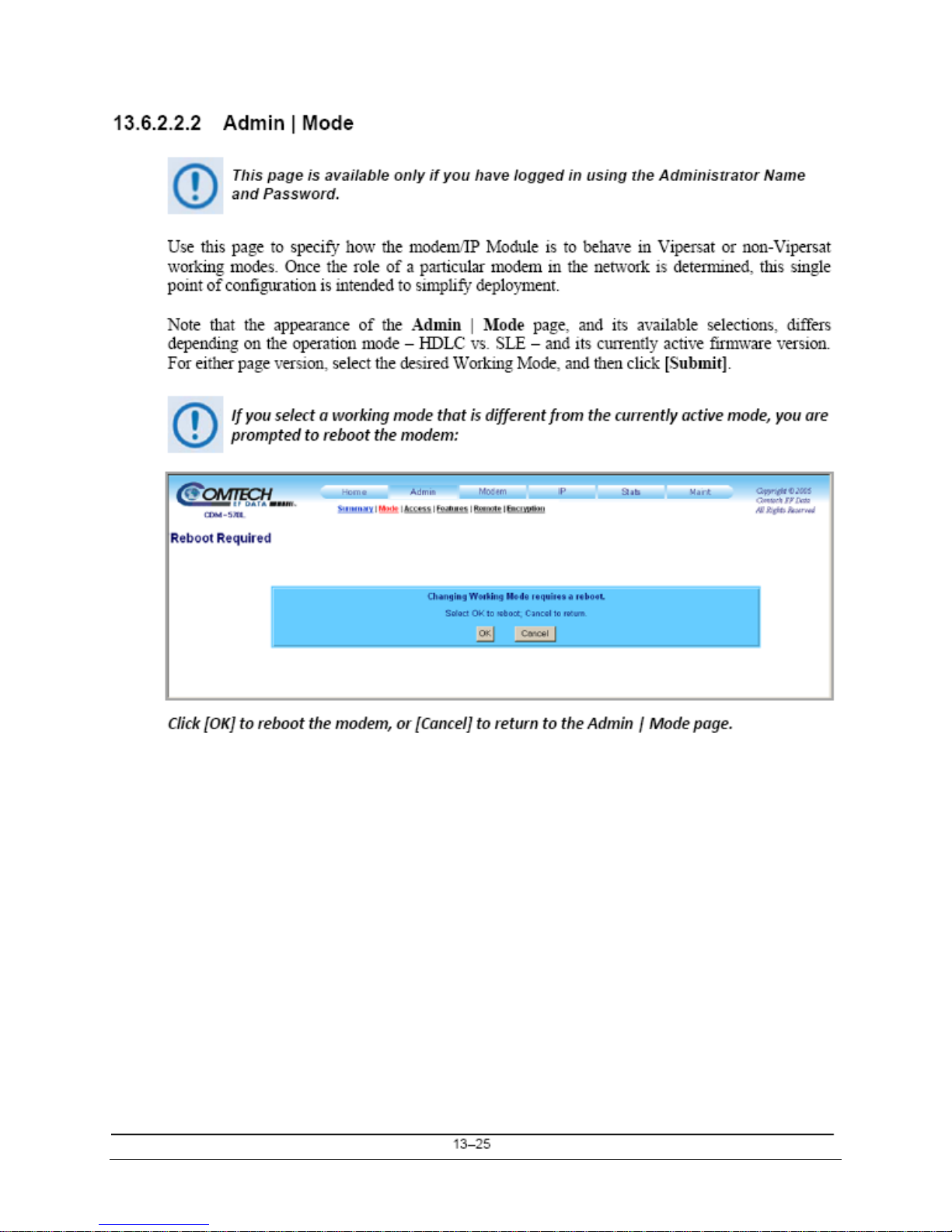
13.6.2.2.2 Admin | Mode ............................................................................................................. 13–25
13.6.2.2.3 Admin | Access ........................................................................................................... 13–28
13.6.2.2.4 Admin | Features ......................................................................................................... 13–29
13.6.2.2.5 Admin | Remote .......................................................................................................... 13–31
13.6.2.2.6 Admin | Encryption ..................................................................................................... 13–32
13.6.2.3 Modem Pages ............................................................................................................................... 13–33
13.6.2.3.1 Modem | Modem ......................................................................................................... 13–33
13.6.2.3.2 Modem | Utilities ........................................................................................................
13–34
13.6.2.3.3 Modem | Status ........................................................................................................... 13–35
13.6.2.3.4 Modem | Logs ............................................................................................................. 13–36
13.6.2.4 IP Pages ......................................................................................................................................... 13–37
13.6.2.4.1 IP | Interface ................................................................................................................ 13–37
13.6.2.4.2 IP | Routes ................................................................................................................... 13–40
13.6.2.4.3 IP | Multicast ............................................................................................................... 13–42
13.6.2.4.4 IP | QoS Mode ............................................................................................................. 13–44
13.6.2.4.5 IP | QoS (Quality of Service) Page ............................................................................. 13–45
13.6.2.4.5.1 IP | QoS (Maximum Bandwidth/Priority Mode) ............................................ 13–45
13.6.2.4.5.2 IP | QoS (Minimum/Maximum Bandwidth Mode) ........................................ 13–47
13.6.2.4.5.3 IP | QoS (DiffServ Mode) .............................................................................. 13–49
13.6.2.4.5.4 IP | QoS (VLAN – Priority/Maximum Bandwidth Mode) ............................. 13–50
13.6.2.4.6 IP | ARP ....................................................................................................................... 13–51
13.6.2.4.7 IP | VLAN ................................................................................................................... 13–52
13.6.2.4.8 IP | IGMP .................................................................................................................... 13–54
13.6.2.4.9 IP | Redundancy .......................................................................................................... 13–55
13.6.2.5 Stats (Statistics) Pages .................................................................................................................. 13–56
13.6.2.5.1 Stats | Ethernet ............................................................................................................ 13–56
13.6.2.5.2 Stats | Routes ............................................................................................................... 13–57
13.6.2.5.3 Stats | QoS ................................................................................................................... 13–58
13.6.2.5.4 Stats | WAN ................................................................................................................ 13–59
13.6.2.5.5 Stats |
Compression ..................................................................................................... 13–60
13.6.2.6 Maint (Maintenance) Pages ......................................................................................................... 13–61
13.6.2.6.1 Maint | Unit Info ......................................................................................................... 13–61
13.6.2.6.2 Maint | Operations ....................................................................................................... 13–62
13.6.2.6.3 Maint | Save ................................................................................................................ 13–63
xi

CDM-570/570L Satellite Modem with Optional IP Module Revision 12
Table of Contents MN/CDM570L.IOM
13.6.2.6.4 Maint | Reboot ............................................................................................................. 13–64
CHAPTER 14. ETHERNET IP MODULE – CLI AND TELNET OPERATION ..................... 14–1
14.1 Overview .................................................................................................................................... 14–1
14.1.1 Interface Access .................................................................................................................. 14–1
14.2 CLI Menu Pages ........................................................................................................................ 14–2
14.2.1 Main Menu Page ................................................................................................................. 14–3
14.2.2 Administration Page ............................................................................................................ 14–4
14.2.2.1 Name/Password Configuration Page ............................................................................................ 14–6
14.2.2.2 Access Lists Page ........................................................................................................................... 14–7
14.2.2.3 Feature Configuration Page ........................................................................................................... 14–8
14.2.2.4 3xDES Encrypt/Decrypt Configuration Page ............................................................................ 14–11
14.2.2.5 SMTP Configuration Page ........................................................................................................... 14–13
14.2.2.6 SNMP Configuration Page .......................................................................................................... 14–14
14.2.2.7 Working Mode ............................................................................................................................. 14–15
14.2.2.8 Managed Switch Multicast Option ............................................................................................. 14–16
14.2.2.9 Header/Payload Compression Refresh Rate ............................................................................... 14–16
14.2.2.10 Payload Compression Refresh Rate ............................................................................................ 14–17
14.2.2.11 Telnet Timeout ............................................................................................................................. 14–17
14.2.3 Interface Configuration Page ............................................................................................ 14–17
14.2.3.1 Ethernet Interface Page ................................................................................................................ 14–18
14.2.3.1.1 VLAN Table ............................................................................................................... 14–19
14.2.
3.2 Satellite/HDLC Interface Page .................................................................................................... 14–20
14.2.3.3 Receive HDLC Channel Addresses Page ................................................................................... 14–21
14.2.4 QoS (Quality of Service) Configuration Page .................................................................. 14–22
14.2.4.1 QoS Rules Configuration Page – Max/Priority Mode ............................................................... 14–23
14.2.4.2 QoS Rules Configuration Page – Min/Max Mode .................................................................... 14–25
14.2.4.3 DiffServ Rules Configuration Page ............................................................................................ 14–26
14.2.5 Route Table Configuration Page ....................................................................................... 14–27
14.2.6 Protocol Configuration Page ............................................................................................. 14–30
14.2.6.1 IGMP Information Page............................................................................................................... 14–31
14.2.6.2 ARP Table Utilities Page ............................................................................................................. 14–33
14.2.6.3 Brouter Configuration Page ......................................................................................................... 14–34
14.2.7 Vipersat Configuration Page ............................................................................................. 14–36
14.2.8 Satellite Modem Page ....................................................................................................... 14–37
14.2.9 Configuration Page ........................................................................................................... 14–38
14.2.9.1 Tx Configuration Page ................................................................................................................. 14–39
14.2.9.2 Rx Configuration Page ................................................................................................................. 14–41
14.2.9.3 Framing Mode Configuration ...................................................................................................... 14–43
14.2.9.4 Data Interface Configuration ....................................................................................................... 14–44
14.2.9.5 Reference Configuration Page ..................................................................................................... 14–45
14.2.9.6 Alarm Mask Configuration .......................................................................................................... 14–46
14.2.
9.7 Block Up Converter (BUC) Configuration ................................................................................ 14–47
14.2.9.8 Low Noise Block Converter (LNB) Configuration ................................................................... 14–48
14.2.10 1:1 Redundancy Configuration Page ............................................................................ 14–49
14.2.11 Operations and Maintenance Page ................................................................................ 14–50
14.2.11.1 Unit Information Page .................................................................................................................. 14–52
xii

CDM-570/570L Satellite Modem with Optional IP Module Revision 12
Table of Contents MN/CDM570L.IOM
14.2.11.2 Statistics Page ............................................................................................................................... 14–53
14.2.11.2.1 IP Routing Statistics Page ........................................................................................... 14–54
14.2.11.2.1.1 Filter/Drop Statistics Page............................................................................ 14–55
14.2.11.2.2 QoS Statistics Page ..................................................................................................... 14–58
14.2.11.2.3 Ethernet Statistics Page ............................................................................................... 14–59
14.2.11.2.4 WAN Statistics ........................................................................................................... 14–60
14.2.11.2.5 Compression Statistics ................................................................................................ 14–62
14.2.11.2.6 CPU Statistics ............................................................................................................. 14–63
14.2.11.2.7 VLAN Statistics .......................................................................................................... 14–63
14.2.11.3 Event Log Page ............................................................................................................................. 14–64
14.2.11.4 Database Operations Page ........................................................................................................... 14–66
14.2.11.5 Diagnostics Page .......................................................................................................................... 14–67
14.3 Telnet Session – Logout Option ............................................................................................. 14–68
APPENDIX A. CABLE DRAWINGS ..................................................................................... A–1
A.1 Overview ..................................................................................................................................... A–1
A.1.1 EIA-530 to EIA-422/449 Data Cable ................................................................................... A–2
A.1.2 EIA-530 to V.35 DCE Conversion Cable ............................................................................ A–3
APPENDIX B. E
MEASUREMENT ................................................................................ B–1
B/N0
APPENDIX C. FAST ACTIVATION PROCEDURE .............................................................. C–1
C.1 FAST System Overview ............................................................................................................. C–1
C.2 FAST Activation Procedure ...................................................................................................... C–2
C.2.1 Record Modem Serial Number ............................................................................................ C–2
C.2.2 View Currently Installed Features ....................................................................................... C–2
C.2.3 Order FAST Options ............................................................................................................ C–2
C.2.4 Enter FAST Access Code .................................................................................................... C–3
C.2.5 Enable / Disable Demo Mode .............................................................................................. C–4
APPENDIX D. SERIAL REMOTE CONTROL ...................................................................... D–1
D.1 Overview ..................................................................................................................................... D–1
D.2 EIA-485 ....................................................................................................................................... D–1
D.3 EIA-232 ....................................................................................................................................... D–2
D.4 Basic Protocol ............................................................................................................................. D–2
D.5 Packet Structure ......................................................................................................................... D–3
D.5.1 Start of Packet ...................................................................................................................... D–3
D.5.2 Target Address ..................................................................................................................... D–3
D.5.3 Address Delimiter ................................................................................................................ D–4
xiii

CDM-570/570L Satellite Modem with Optional IP Module Revision 12
Table of Contents MN/CDM570L.IOM
D.5.4 Instruction Code ................................................................................................................... D–4
D.5.5 Instruction Code Qualifier ................................................................................................... D–4
D.5.6 Optional Message Arguments .............................................................................................. D–6
D.5.7 End Of Packet ...................................................................................................................... D–6
D.6 Remote Commands / Queries .................................................................................................... D–7
D.6.1 Transmit (Tx) Commands and Queries ................................................................................ D–9
D.6.2 Receive (Rx) Commands and Queries ............................................................................... D–14
D.6.3 Unit Commands and Queries ............................................................................................. D–18
D.6.4 Bulk Commands and Queries ............................................................................................ D–29
D.6.5 BUC Commands and Queries (CDM-570L ONLY) ......................................................... D–31
D.6.6 LNB Commands and Queries (CDM-570L ONLY) .......................................................... D–34
APPENDIX E. CDM/CDD NMCS PROTOCOL – REV 1.0 ................................................... E–1
E.1 Revision History ......................................................................................................................... E–1
E.2 Introduction ................................................................................................................................ E–1
E.3 Architecture ................................................................................................................................ E–2
E.4 Command Set Introduction....................................................................................................... E–2
E.4.1 Telnet Interface ..................................................................................................................... E–2
E.4.2 Basic Protocol ....................................................................................................................... E–2
E.4.3 Command Structure .............................................................................................................. E–3
E.4.3.1 Start Of Packet .................................................................................................................................. E–4
E.4.3.2 Target Address ................................................................................................................................. E–4
E.4.3.3 Instruction Code ............................................................................................................................... E–4
E.4.3.
4 Instruction Code Qualifier ............................................................................................................... E–5
E.4.3.5 Optional Message Arguments ......................................................................................................... E–6
E.4.3.6 Table Support Qualifier ................................................................................................................... E–6
E.4.3.6.1 Row Index ...................................................................................................................... E–6
E.4.3.7 Optional Argument lists ................................................................................................................... E–7
E.4.3.8 End Of Packet ................................................................................................................................... E–7
E.5 Remote Commands and Queries .............................................................................................. E–8
E.5.1 IP Commands and Queries .................................................................................................... E–9
E.5.1.1 Admin Commands and Queries ...................................................................................................... E–9
E.5.2 Interface Commands and Queries ....................................................................................... E–16
E.5.3 QoS Commands and Queries .............................................................................................. E–17
E.5.4 Protocol Commands and Queries ........................................................................................ E–20
E.5.5 Operations and Maintenance Commands and Queries ....................................................... E–22
E.5.6 Redundancy Queries ........................................................................................................... E–24
E.5.7 Routing Commands and Queries ........................................................................................ E–25
E.5.8 Statistics Commands and Queries ....................................................................................... E–27
E.5.8.1 WAN Stats ...................................................................................................................................... E–27
E.5.8.2 IP Statistics Commands and Queries ............................................................................................ E–28
E.5.8.3 Ethernet Statistics Commands and Queries .................................................................................. E–30
E.5.8.4 Quality of Service (QoS) Statistics Commands and Queries ...................................................... E–31
xiv

CDM-570/570L Satellite Modem with Optional IP Module Revision 12
Table of Contents MN/CDM570L.IOM
E.6 PARAM Files ............................................................................................................................ E–32
APPENDIX F. IP QUICK-START GUIDE .............................................................................. F–1
F.1 Quick-Start Guide Introduction ................................................................................................ F–1
F.2 Getting Started ............................................................................................................................ F–1
F.2.1 Equipment List ...................................................................................................................... F–1
F.2.2 Equipment Setup ................................................................................................................... F–2
F.2.3 Transmit and Receive IF Configuration ................................................................................ F–2
F.2.4 Serial Console Port Command Line Interface (CLI) Configuration ..................................... F–2
F.2.5 CLI Main Menu .................................................................................................................... F–3
F.2.6 Restoring Factory Default Configuration.............................................................................. F–3
F.3 Managed Switch Point-to-Point System Configuration ........................................................... F–4
F.3.1 PC Configuration .................................................................................................................. F–4
F.3.2 CDM-IP Configuration – Setting IP Address(es) ................................................................ F–4
F.4 Router Mode Point-to-Point System Configuration ................................................................ F–5
F.4.1 PC Configuration .................................................................................................................. F–5
F.4.2 Setting CDM-IP Modems to Router Mode Operation .......................................................... F–6
F.4.3 Setting IP Address(es) ........................................................................................................... F–6
F.4.4 Set Route Table entries ......................................................................................................... F–6
F.5 Troubleshooting IP Module ....................................................................................................... F–8
F.5.1 Managed Switch Mode Troubleshooting .............................................................................. F–8
F.5.2 Router Mode Troubleshooting ............................................................................................ F–10
APPENDIX G. ETHERNET IP MODULE – TYPICAL OPERATIONAL SETUPS ................ G–1
G.1 Overview ..................................................................................................................................... G–1
G.2 Modem Compatibility ................................................................................................................ G–1
G.3 IP Module Working Modes
....................................................................................................... G–2
G.3.1 Working Modes – HDLC Encapsulation ............................................................................. G–2
G.3.2 Working Modes – Streamline Encapsulation ....................................................................... G–3
G.3.3 Managed Switch Mode ........................................................................................................ G–5
G.3.4 Router Modes ....................................................................................................................... G–6
G.3.4.1 Router Mode – Point-to-Point ........................................................................................................ G–6
G.3.4.2 Router Mode – Point-to-MultiPoint ............................................................................................... G–7
G.3.4.3 Router Mode (Brouter Enabled) – Point-to-MultiPoint with VLAN Matching Filters ............ G–11
G.3.4.3.1 Sample Network #1 – VLAN Filtering Disabled ....................................................... G–11
G.3.4.3.2 Sample Network #2 – VLAN Filtering Enabled ........................................................ G–12
G.3.4.3.3 Brouter Mode with VLAN Filtering Configuration ................................................... G–12
APPENDIX H. IP REDUNDANCY ........................................................................................ H–1
H.1 Introduction ................................................................................................................................ H–1
xv

CDM-570/570L Satellite Modem with Optional IP Module Revision 12
Table of Contents MN/CDM570L.IOM
H.2 CRS-XXX 1:1 Redundancy Switch Functional Description .................................................. H–1
H.2.1 CRS-180 70/140 MHz 1:1 Redundancy Switch .................................................................. H–1
H.2.2 CRS-170A L-Band 1:1 Redundancy Switch........................................................................ H–2
H.3 CDM-570/570L 1:1 IP Data Switching Functional Description ............................................. H–3
H.4 CDM-570/570L 1:1 IP Redundancy Configuration ................................................................ H–5
H.5 Cabling With CDM-570 IF ........................................................................................................ H–7
H.6 Cabling With CDM-570L .......................................................................................................... H–8
APPENDIX J. GPS MODE ..................................................................................................... J–1
J.1 Overview ...................................................................................................................... ................ J–1
J.2 Hardware Setup .......................................................................................................................... J–1
J.3 Remote Commands ..................................................................................................................... J–2
APPENDIX K. CDM-570 ODU (CSAT-5060 OR KST-2000A/B) OPERATION ................... K–1
K.1 Introduction ................................................................................................................................ K–1
K.2 ODU Remote Control Address Setup ....................................................................................... K–1
K.3 ODU Operations via the CDM-570 Front Panel ..................................................................... K–2
K.3.1 CDM-570 Front Panel Operation – Overview ..................................................................... K–2
K.3.2 CDM-570 Front Panel Operation – ODU Menu Hierarchy ................................................. K–3
K.3.3 SELECT: (Main) Menu ....................................................................................................... K–4
K.3.3.1 (SELECT:) ODU ............................................................................................................................. K–4
K.3.3.1.1 (SELECT:) ODU – CSAT-5060 Transceiver Operation .............................................. K–5
K.3.3.1.1.1 ODU (Transceiver Control): Enable .................................................................. K–6
K.3.3.1.1.1.1 COMMON ‘ODU SELECT’ SUBMENU .................................................. K–8
K.3.3.1.1.1.1.1 ODU SELECT: Config ........................................................................ K–8
K.3.3.1.
1.1.1.2 ODU SELECT: Info ........................................................................... K–12
K.3.3.1.1.1.1.3 ODU SELECT: Monitor .................................................................... K–13
K.3.3.1.1.1.1.4 ODU SELECT: Alarms ...................................................................... K–14
K.3.3.1.2 (SELECT:) ODU – KST-2000A/B Transceiver Operation ............................. K–15
K.3.3.1.2.1 ODU (Transceiver Control): Enable ................................................................ K–15
K.3.3.1.2.1.1 (ODU) Enable: Config (KST Configuration) ............................................ K–15
K.3.3.1.2.1.2 (ODU) Enable: INFO (Information) ......................................................... K–20
K.3.3.1.2.1.3 (ODU: Enable) Status................................................................................ K–21
K.4 ODU Operations via the CDM-570 Base Modem HTTP Interface ..................................... K–22
K.4.1 ODU-Accessible Base Modem HTTP Interface – Overview ............................................ K–22
K.4.1.1 Base Modem HTTP Interface – Home Page and Menu Tree .................................................... K–22
K.4.1.2 ODU (Outdoor Unit) pages .......................................................................................................... K–23
K.4.1.2.1 ODU | Config Pages .................................................................................................... K–24
xvi

CDM-570/570L Satellite Modem with Optional IP Module Revision 12
Table of Contents MN/CDM570L.IOM
K.4.1.2.1.1 ODU | Config (CSAT-5060) ............................................................................ K–24
K.4.1.2.1.2 ODU | Config (KST-2000A/B) ........................................................................ K–26
K.4.1.2.2 ODU | Status Pages ...................................................................................................... K–27
K.4.1.2.2.1 ODU | Status (CSAT-5060) ............................................................................. K–27
K.4.1.2.2.2 ODU | Status (KST-2000A/B) ......................................................................... K–28
K.4.1.2.3 ODU | Utilities Pages ................................................................................................... K–29
K.4.1.2.3.1 ODU | Utilities (CSAT-5060) .......................................................................... K–29
K.4.1.2.3.2 ODU | Utilities (KST-2000A/B) ...................................................................... K–30
APPENDIX L. CDM-570L ODU (BUC, LNB) OPERATION .................................................. L–1
L.1 Introduction ................................................................................................................................ L–1
L.2 ODU Remote Control Address Setup ....................................................................................... L–1
L.3 ODU Operations via the CDM-570L Front Panel .................................................................. L–2
L.3.1 CDM-570L Front Panel Operation Overview ....................................................................... L–2
L.3.2 CDM-570L Front Panel Operation – ODU Menu Hierarchy ............................................... L–3
L.3.3 SELECT: (Main) Menu ........................................................................................................ L–4
L.3.3.1 (SELECT:) Config (Configuration) ................................................................................................ L–5
L.3.3.1.1 CONFIG: Mask ............................................................................................................. L–5
L.3.3.1.1.1 (CONFIG: Mask) Alarm Mask: BUC ................................................................. L–5
L.3.3.1.1.2 (CONFIG: Mask) Alarm Mask: LNB .................................................................. L–5
L.3.3.1.2 CONFIG: ODU (Outdoor Unit) .................................................................................... L–5
L.3.3.1.2.1 (CONFIG: ODU (Outdoor Unit)) BUC ............................................................... L–5
L.3.3.1.2.1.1 (CONFIG: ODU (Outdoor Unit)) BUC: M&C-FSK .................................... L–6
L.3.3.1.2.1.2 (CONFIG: ODU (Outdoor Unit)) BUC: DC-Power ..................................... L–6
L.3.3.
1.2.1.3 (CONFIG: ODU (Outdoor Unit)) BUC: 10MHz ......................................... L–6
L.3.3.1.2.1.4 (CONFIG: ODU (Outdoor Unit)) BUC: Alarm ........................................... L–7
L.3.3.1.2.1.5 (CONFIG: ODU (Outdoor Unit)) BUC: LO ................................................ L–7
L.3.3.1.2.1.6 (CONFIG: ODU (Outdoor Unit)) BUC: Mix ............................................... L–7
L.3.3.1.2.2 (CONFIG: ODU (Outdoor Unit)) LNB ............................................................... L–8
L.3.3.1.2.2.1 (CONFIG: ODU (Outdoor Unit)) LNB: DC-Voltage .................................. L–8
L.3.3.1.2.2.2 (CONFIG: ODU (Outdoor Unit)) LNB: 10MHz .......................................... L–8
L.3.3.1.2.2.3 (CONFIG: ODU (Outdoor Unit)) LNB: Alarm ............................................ L–8
L.3.3.1.2.2.4 (CONFIG: ODU (Outdoor Unit)) LNB: LO................................................. L–9
L.3.3.1.2.2.5 (CONFIG: ODU (Outdoor Unit)) LNB: Mix ............................................... L–9
L.3.3.2 (SELECT:) Monitor ....................................................................................................................... L–10
L.3.3.2.1 MONITOR: Alarms ..................................................................................................... L–10
L.3.3.2.1.1 (MONITOR: Live Alarms) ODU ...................................................................... L–10
L.3.3.2.2 MONITOR: ODU ........................................................................................................ L–11
L.3.3.2.2.1 (MONITOR: Outdoor Unit Monitor) BUC ....................................................... L–11
L.3.3.2.2.2 (MONITOR: Outdoor Unit Monitor) LNB ....................................................... L–11
L.4 ODU Operations via the CDM-570L Base Modem HTTP Interface .................................. L–12
L.4.1 ODU-Accessible Base Modem HTTP Interface – Overview ............................................. L–12
L.4.1.1 Base Modem HTTP Interface – Home Page and Menu Tree ..................................................... L–12
L.4.2 ODU (BUC, LNB) Pages .................................................................................................... L–13
L.4.2.1 Config Mdm | BUC (Block Up Converter) .................................................................................. L–13
xvii

CDM-570/570L Satellite Modem with Optional IP Module Revision 12
Table of Contents MN/CDM570L.IOM
L.4.2.2 Config Mdm | LNB (Low-Noise Block Down Converter) ......................................................... L–14
L.5 ODU Operations via the CDM-570L IP Module HTTP Interface ...................................... L–15
L.5.1 ODU-Accessible IP Module HTTP Interface – Overview .................................................. L–15
L.5.1.1 IP Module HTTP Interface – Home Page and Menu Tree .......................................................... L–15
L.5.2 ODU Configuration Pages .................................................................................................. L–16
L.5.2.1 Modem | BUC (Block Up Converter) ........................................................................................... L–16
L.5.2.2 Modem | LNB (Low-Noise Block Down Converter) .................................................................. L–17
TABLES
Table 1-1. Summary of CDM-570/570L Rear Panel Connectors ............................................................. 1–6
Table 3-1. Rear Panel External Connections ........................................................................................... 3–2
Table 3-2. Data Interface Connector Pin Assignments ............................................................................ 3–4
Table 3-3. Balanced G.703 Interface Connector Pin Assignments .......................................................... 3–5
Table 3-4. Typical Ethernet Interface Port Pin Assignments ................................................................... 3–7
Table 3-5. Remote Control Interface Connector Pin Assignments .......................................................... 3–8
Table 3-6. Alarm Interface Connector Pin Assignments ......................................................................... 3–9
Table 3-7. 1:1 Control Interface Connector Pin Assignments ................................................................. 3–9
Table 3-8. ASYNC-Serial Console Connector Pin Assignments .......................................................... 3–10
Table 8-1. Viterbi Decoding Summary .................................................................................................... 8–2
Table 8-2. Concatenated RS Coding Summary ....................................................................................... 8–3
Table 8-3. 8-PSK/TCM Coding Summary .............................................................................................. 8–4
Table 8-4. Available TPC Modes ............................................................................................................ 8–5
Table 8-5. Turbo Product Coding Processing Delay Comparison ........................................................... 8–6
Table 8-6. Turbo Product Coding Summary ............................................................................................ 8–8
Table 13-1. Streamline Encapsulation .................................................................................................... 13–6
FIGURES
Figure 1-1. CDM-570/570L Satellite Modem .......................................................................................... 1–1
Figure 1-2. CDM-570/570L Dimensional Envelope ................................................................................ 1–4
Figure 1-3. Front Panel View .................................................................................................................... 1–5
Figure 1-4. Rear Panel View ..................................................................................................................... 1–5
Figure 2-1. Unpacking and Inspecting the Shipment ................................................................................ 2–1
Figure 2-2. Installation into a Rack Enclosure .......................................................................................... 2–3
Figure 2-3. Optional Rear-Mounting Support Brackets Kit Installation ................................................... 2–4
Figure 3-1. CDM-570/570L Rear Panel ................................................................................................... 3–1
Figure 3-2. CN-0000268 DB-15M Æ RJ-48F Adapter for E1/T1 Operation........................................... 3–6
Figure 5-1. Front Panel View (CDM-570L shown) .................................................................................. 5–1
Figure 5-2. CDM-570/570L – Front Panel Keypad .................................................................................. 5–3
Figure 5-3. CDM-570/570L Menu Tree (FW Ver. 1.6.15) ....................................................................... 5–6
Figure 5-4. Loopback Modes .................................................................................................................. 5–40
Figure 7-1. CDM-570 “Splash” page ........................................................................................................ 7–3
Figure 7-2. CDM-570L “Splash” page ..................................................................................................... 7–4
Figure 7-3. Satellite Modem Home page (CDM-570L shown) ................................................................ 7–5
xviii

CDM-570/570L Satellite Modem with Optional IP Module Revision 12
Table of Contents MN/CDM570L.IOM
Figure 7-4. Home | Contact page .............................................................................................................. 7–6
Figure 7-5. Home | Customer Support page .............................................................................................. 7–7
Figure 7-6. Admin | Access page .............................................................................................................. 7–8
Figure 7-7. Admin | Remote page ........................................................................................................... 7–10
Figure 7-8. Config Mdm | Modem page ................................................................................................. 7–11
Figure 7-9. Config Mdm | Modem Utilities page ................................................................................... 7–12
Figure 7-10. Config Mdm | AUPC page ................................................................................................. 7–14
Figure 7-12. Stats | Modem Status page .................................................................................................. 7–15
Figure 7-13. Stats | Modem Logs page ................................................................................................... 7–16
Figure 7-15. Maint (Maintenance) page ................................................................................................. 7–17
Figure 8-1. Viterbi Decoding .................................................................................................................. 8–10
Figure 8-2. Viterbi with Concatenated RS Outer Code .......................................................................... 8–11
Figure 8-3. 8-PSK/TCM Rate 2/3 with Concatenated RS Outer Code ................................................... 8–12
Figure 8-4. Rate 3/4 QPSK/OQPSK, 8-PSK AND 16-QAM Turbo ...................................................... 8–13
Figure 8-5. Rate 7/8 QPSK/OQPSK, 8-PSK AND 16-QAM Turbo ...................................................... 8–14
Figure 8-6. Rate 21/44 QPSK, Rate 0.95 QPSK and Rate 0.95 8-PSK Turbo ....................................... 8–15
Figure 8-7. Rate 21/44 BPSK and Rate 5/16 BPSK Turbo ..................................................................... 8–16
Figure 8-8. Rate 3/4 and Rate 0.95 8-QAM Turbo ................................................................................. 8–17
Figure 8-9. Rate 7/8 8-QAM Turbo ........................................................................................................ 8–18
Figure 8-10. 16-QAM Viterbi, Rate 3/4 and Rate 7/8 with 220,200 RS Outer Code ............................. 8–19
Figure 8-11. Differential Encoding – No FEC, No Scrambling ............................................................. 8–20
Figure 10-1. Tx Clock Modes ................................................................................................................ 10–4
Figure 10-2. Rx Clock Modes ................................................................................................................ 10–5
Figure 10-3. G.703 Clock Extension Mode 1 ......................................................................................... 10–8
Figure 10-4. G.703 Clock Extension Mode 2 ......................................................................................... 10–9
Figure 10-5. G.703 Clock Extension Mode 3 ....................................................................................... 10–10
Figure 13-1. CDM-570/570L IP Module HTTP Interface “Splash” page ............................................ 13–18
Figure 13-2. Home | Home Page ........................................................................................................... 13–20
Figure 13-3. Home | Contact page ........................................................................................................ 13–21
Figure 13-4. Home | Customer Support page ........................................................................................ 13–22
Figure 13-5. Info | Logoff page ............................................................................................................. 13–23
Figure 13-6. Admin |Summary page ..................................................................................................... 13–24
Figure 13-7. Admin | Mode page (prior to Firmware Ver. 1.6.#) ......................................................... 13–25
Figure 13-8. Admin | Mode page (Firmware Ver. 1.6.# and later) ....................................................... 13–26
Figure 13-9. Admin | Access page ........................................................................................................ 13–28
Figure 13-10. Admin | Features page .................................................................................................... 13–29
Figure 13-11. Admin | Remote page ..................................................................................................... 13–31
Figure 13-12. Admin | Encryption page ................................................................................................ 13–32
Figure 13-13. Modem | Modem page .................................................................................................... 13–33
Figure 13-14. Modem | Utilities page ................................................................................................... 13–34
Figure 13-15. Modem | Status page ...................................................................................................... 13–35
Figure 13-16. Modem | Logs page ........................................................................................................ 13–36
Figure 13-17. IP | Interface page ........................................................................................................... 13–37
Figure 13-18. IP | Routes page .............................................................................................................. 13–40
Figure 13-19. IP | Multicast page .......................................................................................................... 13–42
Figure 13-20. IP | QoS Mode page ....................................................................................................... 13–44
Figure 13-21. IP | QoS page (Max/Priority Mode) ............................................................................... 13–45
Figure 13-22. IP | QoS Mode page (Min/Max Mode) .......................................................................... 13–47
Figure 13-23. IP | QoS Mode page (DiffServ Mode) ............................................................................ 13–49
Figure 13-24. IP | QoS Mode page (VLAN – Priority/Max Mode) ...................................................... 13–50
xix

CDM-570/570L Satellite Modem with Optional IP Module Revision 12
Table of Contents MN/CDM570L.IOM
Figure 13-25. IP | ARP page ................................................................................................................. 13–51
Figure 13-26. IP | VLAN page .............................................................................................................. 13–52
Figure 13-27. IP | IGMP ....................................................................................................................... 13–54
Figure 13-28. IP | Redundancy page ..................................................................................................... 13–55
Figure 13-29. Stats | Ethernet page ....................................................................................................... 13–56
Figure 13-30. Stats | Routes page .......................................................................................................... 13–57
Figure 13-31. Stats | QoS page .............................................................................................................. 13–58
Figure 13-32. Stats | WAN page ........................................................................................................... 13–59
Figure 13-33. Stats | Compression page ................................................................................................ 13–60
Figure 13-34. Maint | Unit Info page .................................................................................................... 13–61
Figure 13-35. Maint | Operations page ................................................................................................. 13–62
Figure 13-36. Maint | Save page ........................................................................................................... 13–63
Figure 13-37. Maint | Reboot page ....................................................................................................... 13–64
Figure 14-1. Main Menu page................................................................................................................. 14–3
Figure 14-2. Administration page ........................................................................................................... 14–4
Figure 14-3. Name/Password Configuration page .................................................................................. 14–6
Figure 14-4. Access Lists page ............................................................................................................... 14–7
Figure 14-5. Feature Configuration page ................................................................................................ 14–8
Figure 14-6. 3xDES Encrypt Configuration page ................................................................................. 14–11
Figure 14-7. SMTP Configuration page ............................................................................................... 14–13
Figure 14-8. SNMP Configuration page ............................................................................................... 14–14
Figure 14-9. Interface Configuration page ............................................................................................ 14–17
Figure 14-10. Ethernet Interface page ................................................................................................... 14–18
Figure 14-11. VLAN Table ................................................................................................................... 14–19
Figure 14-12. Satellite/HDLC Interface page ....................................................................................... 14–20
Figure 14-13. Receive HDLC Channel Addresses page ....................................................................... 14–21
Figure 14-14. QoS Configuration page ................................................................................................. 14–22
Figure 14-15. QoS Rules Configuration page (Max/Priority mode) ..................................................... 14–23
Figure 14-16. QoS Rules Configuration page (Min/Max mode) .......................................................... 14–25
Figure 14-17. DiffServ Rules Configuration page ................................................................................ 14–26
Figure 14-18. Route Table Configuration page .................................................................................... 14–27
Figure 14-19. Protocol Configuration Page .......................................................................................... 14–30
Figure 14-20. IGMP Information page ................................................................................................. 14–31
Figure 14-21. ARP Table Utilities page ................................................................................................ 14–33
Figure 14-22. Brouter Configuration page ............................................................................................ 14–34
Figure 14-23. Vipersat Configuration page .......................................................................................... 14–36
Figure 14-24. Modem Parameters Page ................................................................................................ 14–37
Figure 14-25. Modem Configuration page ........................................................................................... 14–38
Figure 14-26. Tx (Transmit Modem) Configuration Page .................................................................... 14–39
Figure 14-27. Rx (Receive Modem) Configuration Page ..................................................................... 14–41
Figure 14-28. Framing Mode Configuration Page ................................................................................ 14–43
Figure 14-29. Data Interface Configuration Page ................................................................................. 14–44
Figure 14-30. Reference Configuration Page ....................................................................................... 14–45
Figure 14-31. Alarm Mask Configuration Page .................................................................................... 14–46
Figure 14-32. Block Up Converter (BUC) Configuration Page ........................................................... 14–47
Figure 14-33. Low Noise Block Converter (LNB) Configuration Page ............................................... 14–48
Figure 14-34. 1:1 Redundancy Configuration page ..............................................................................
Figure 14-35.
Operations and Maintenance page ................................................................................. 14–50
14–49
Figure 14-36. Unit Information page .................................................................................................... 14–52
Figure 14-37. Statistics Menu ............................................................................................................... 14–53
xx

CDM-570/570L Satellite Modem with Optional IP Module Revision 12
Table of Contents MN/CDM570L.IOM
Figure 14-38. IP Statistics page ............................................................................................................ 14–54
Figure 14-39. Filter/Drop Statistics page .............................................................................................. 14–55
Figure 14-40. QoS Statistics Page......................................................................................................... 14–58
Figure 14-41. Ethernet Statistics page .................................................................................................. 14–59
Figure 14-42. WAN Statistics page ...................................................................................................... 14–60
Figure 14-43. Compression Statistics page ........................................................................................... 14–62
Figure 14-44. CPU Statistics page ........................................................................................................ 14–63
Figure 14-45. VLAN Statistics page ..................................................................................................... 14–63
Figure 14-46. Event Log page............................................................................................................... 14–64
Figure 14-47. Database Operations page .............................................................................................. 14–66
Figure 14-48. Diagnostics Page ............................................................................................................ 14–67
Figure 14-49. Logout via Telnet Session .............................................................................................. 14–68
Figure A-1. CDM-570/570L EIA-530 to EIA-422/449 DCE Conversion Cable (CEFD Dwg. No.
CA/WR12753) ................................................................................................................................. A–2
Figure A-2. CDM-570/570LL EIA-530 to V.35 DCE Conversion Cable (CEFD Dwg. No. CA/WR12685)
......................................................................................................................................................... A–3
Figure E-1. Basic Architecture Layout .................................................................................................... E–2
Figure F-1. CLI Main Menu ..................................................................................................................... F–3
Figure F-2. Managed Switch Point-to-Point System Configuration ......................................................... F–4
Figure F-3. Router Mode Point-to-Point System Configuration ............................................................... F–5
Figure G-1. Managed Switch Mode ......................................................................................................... G–5
Figure G-2. Router Point-to-Point Working Mode .................................................................................. G–6
Figure G-3. Router Point-to-MultiPoint Working Mode w/HDLC ......................................................... G–7
Figure G-4. Router Point-to-MultiPoint Mode with Streamline Encapsulation ...................................... G–8
Figure G-5. Brouter Point-to-MultiPoint Working Mode w/VLAN Filtering ....................................... G–15
Figure H-1. CDM-570 1:1 IP Redundancy .............................................................................................. H–3
Figure H-2. CDM-570 1:1 IP Redundancy Switchover ........................................................................... H–4
Figure H-3. CDM-570 and CRS-180 Interconnect .................................................................................. H–7
Figure H-4. CDM-570L and CRS-170A Interconnect ............................................................................. H–8
Figure K-1. CDM-570 Front Panel View ................................................................................................ K–2
Figure K-2. CDM-570 Menu Tree – ODU Operation ............................................................................. K–3
Figure K-3. ODU: CSAT-5060 Transceiver Menu Tree ......................................................................... K–5
Figure K-4. ODU: KST-2000A/B Transceiver Menu Tree ................................................................... K–15
Figure K-5. ODU | Config page (CSAT-5060) ...................................................................................... K–24
Figure K-6. ODU | Config page (KST-2000A/B) .................................................................................. K–26
Figure K-7. ODU | Status page (CSAT-5060) ....................................................................................... K–27
Figure K-8. ODU | Status page (KST-2000A/B) ................................................................................... K–28
Figure K-9. ODU | Utilities page (CSAT-5060) .................................................................................... K–29
Figure K-10. ODU | Utilities page (KST-2000A/B) .............................................................................. K–30
Figure L-1. CDM-570L Front Panel View ............................................................................................... L–2
Figure L-2. CDM-570L Menu Tree – ODU Operation ............................................................................ L–3
Figure L-3. Config Mdm | BUC page ..................................................................................................... L–13
Figure L-4. Config Mdm | LNB page ..................................................................................................... L–14
Figure L-5. Modem | BUC page ............................................................................................................. L–16
Figure L-6. Modem | LNB page .............................................................................................................. L–17
xxi

CDM-570/570L Satellite Modem with Optional IP Module Revision 12
Table of Contents MN/CDM570L.IOM
This page is intentionally blank.
xxii

About this Manual
This manual provides installation and operation information for the Comtech EF Data CDM-570
or CDM-570L/CDMR-570L Satellite Modems (collectively referred to throughout the remainder
of this manual as the CDM-570/570L). These modems are essentially identical in their operation,
with the following differences:
• The CDM-570 operates in the 70/140MHz IF band and includes support for externally
connected Comtech EF Data Transceivers (CSAT-5060, KST-2000A/B);
• The CDM-570L and CDMR-570L operate at L-band and include support for externally
connected Block Upconverters (BUCs) and Low-Noise Block Downcoverters (LNBs).
This is a technical document intended for the persons responsible for the operation and
maintenance of the Comtech EF Data CDM-570/570L.
PREFACE
Reporting Comments or Suggestions Concerning this Manual
Comments and suggestions regarding the content and design of this manual are appreciated. To
submit comments, please contact the Comtech EF Data Technical Publications Department:
TechnicalPublications@comtechefdata.com
.
Conventions and References
Patents and Trademarks
See all of Comtech EF Data's Patents and Patents Pending at http://patents.comtechefdata.com.
Comtech EF Data acknowledges that all trademarks are the property of the trademark owners.
xxiii

CDM-570/570L Satellite Modem with Optional IP Module Revision 12
Preface MN/CDM570L.IOM
Warnings, Cautions, and Notes
A WARNING
or SERIOUS INJURY.
A CAUTION
or PROPERTY DAMAGE.
A NOTE
A REFERENCE
equipment.
gives information about a possible hazard that MAY CAUSE DEATH
gives information about a possible hazard that MAY CAUSE INJURY
gives important information about a task or the equipment.
directs the user to additional information about a task or the
Examples of Multi-Hazard Notices
Metric Conversion
Metric conversion information is located on the inside back cover of this manual. This
information is provided to assist the operator in cross-referencing non-Metric to Metric
conversions.
Recommended Standard Designations
Recommended Standard (RS) Designations have been superseded by the new designation of the
Electronic Industries Association (EIA). References to the old designations may be shown when
depicting actual text displayed on the Web or Telnet (i.e., remote control) interface pages for the
unit (e.g., RS-232). All other references in the manual will be shown with the EIA designations.
xxiv

CDM-570/570L Satellite Modem with Optional IP Module Revision 12
Preface MN/CDM570L.IOM
The user should carefully review the following information:
Safety and Compliance
Electrical Safety and Compliance
The unit complies with the EN 60950 Safety of Information Technology Equipment
(Including Electrical Business Machines) safety standard.
IF THE UNIT IS OPERATED IN A VEHICLE OR MOVABLE INSTALLATION, MAKE
SURE THE UNIT IS STABLE. OTHERWISE, EN 60950 SAFETY IS NOT
GUARANTEED.
Electrical Installation
Fuses
CONNECT THE UNIT TO A POWER SYSTEM THAT HAS SEPARATE GROUND,
LINE AND NEUTRAL CONDUCTORS. DO NOT CONNECT THE UNIT WITHOUT A
DIRECT CONNECTION TO GROUND.
The unit is rated for operation over the range 100 to 240 volts AC. It has a maximum power
consumption of 250 Watts (when equipped with a 150W BUC power supply), and draws a
maximum of 2.5 Amps.
FOR CONTINUED OPERATOR SAFETY, ALWAYS REPLACE THE FUSES WITH
THE CORRECT TYPE AND RATING.
The 230 or 115 volt AC-powered CDM-570L or CDM-570 is fitted with two 20mm slow blow
fuses – one each for line and neutral connections. They are contained wit hin a fus e holder that is
press-fit into the body of the IEC power module.
• For 230 volt AC operation, use T2.5A fuses.
• For 115 volt AC operation, use T5.0A (P/N 5ASB-IEC) fuses.
CDM-570/570L Optional 48V DC Units: The 48 volt DC-powered CDM-570L or CDM-570 is
fitted with two 20mm slow blow fuses – one each for positive and negativ e connections. They are
contained within a fuse holder that is press-fit into the body of the IEC power module.
• For 42 to 60 volt DC operation, use T5.0A fuses if the modem has no BUC power supply.
• For 42 to 60 volt DC operation, use T8.0A fuses if the modem is fitted with an internal
BUC power supply.
xxv

CDM-570/570L Satellite Modem with Optional IP Module Revision 12
Preface MN/CDM570L.IOM
CDMR-570L 48V DC Units: The 48 volt DC-powered CDMR-570L is fitted with one Type TR5
Slow-Blow fuse contained within a screw-in receptacle located to the left of the terminal block.
• For 42 to 60 volt DC operation, use TR5 6.3A fuses if the modem has no BUC power
supply.
CDM-570/570L Optional 24V DC Units: The 24 volt DC-powered CDM-570L or CDM-570 is
fitted with two 20mm Slow-Blow fuses – one each for positive and neg ative connection s. They are
contained within a fuse holder that is press-fit into the body of the IEC power module.
• For 20 to 36 volt DC operation, use a T5.0A fuse if the modem has no BUC power supply.
• For 20 to 36 volt DC operation, use a T10.0A fuse if the modem is fitted with an internal
BUC power supply.
Operating Environment
DO NOT OPERATE THE UNIT IN ANY OF THESE EXTREME OPERATING
CONDITIONS:
• AMBIENT TEMPERATURES LESS THAN 0° C (32° F) OR MORE THAN 50°
C (122° F).
• PRECIPITATION, CONDENSATION, OR HUMID ATMOSPHERES OF MORE
THAN 95% RELATIVE HUMIDITY.
• UNPRESSURIZED ALTITUDES OF MORE THAN 2000 METRES (6561.7
FEET).
• EXCESSIVE DUST.
• FLAMMABLE GASES.
• CORROSIVE OR EXPLOSIVE ATMOSPHERES.
European Union Radio Equipment and Telecommunications Terminal
Equipment (R&TTE) Directive (1999/5/EC) and EN 301 489-1
Independent testing verifies that the unit complies with the European Union R&TTE Directive, its
reference to EN 301 489-1 (Electromagnetic compatibility and Radio spectrum Matters [ERM];
ElectroMagnetic Compatibility [EMC] standard for radio equipment and services, Part 1:
Common technical requirements), and the Declarations of Conformity for the applicable
directives, standards, and practices that follow:
European Union Electromagnetic Compatibility (EMC) Directive
(2004/108/EC)
• Emissions: EN 55022 Class B – Limits and Methods of Measurement of Radio
Interference Characteristics of Information Technology Equipment.
xxvi

CDM-570/570L Satellite Modem with Optional IP Module Revision 12
Preface MN/CDM570L.IOM
• Immunity: EN 55024 – Information Technology Equipment: Immunity Characteristics,
Limits, and Methods of Measurement.
• EN 61000-3-2 – Harmonic Currents Emission
• EN 61000-3-3 – Voltage Fluctuations and Flicker.
• Federal Communications Commission Federal Code of Regulation FCC Part 15,
Subpart B.
TO ENSURE THAT THE UNIT COMPLIES WITH THESE STANDARDS, OBEY
THESE INSTRUCTIONS:
• Use coaxial cable that is of good quality for connections to the L-Band Type ‘N’ Rx
(receive) female connector.
• Use Type 'D' connectors that have back-shells with continuous metallic shielding.
Type ‘D’ cabling must have a continuous outer shield (either foil or braid, or both). The
shield must be bonded to the back-shell.
• Operate the unit with its cover on at all times.
European Union Low Voltage Directive (LVD) (2006/95/EC)
Symbol Description
<HAR> Type of power cord required for use in the European Community.
!
CAUTION: Double-pole/Neutral Fusing
ACHTUNG: Zweipolige bzw. Neutralleiter-Sicherung
International Symbols
Symbol Definition Symbol Definition
AlternatingCurrent
Fuse
ProtectiveEarth
ChassisGround
For additional symbols, refer to Warnings, Cautions and Notes listed earlier in this
Preface.
European Union RoHS Directive (2002/95/EC)
This unit satisfies (with exemptions) the requirements specified in the European Union Directive
on the Restriction of Hazardous Substances in Electrical and Electronic Equipment (EU RoHS,
Directive 2002/95/EC).
xxvii

CDM-570/570L Satellite Modem with Optional IP Module Revision 12
Preface MN/CDM570L.IOM
European Union Telecommunications Terminal Equipment Directive
(91/263/EEC)
In accordance with the European Union Telecommunications Terminal Equipment Directive
91/263/EEC, the unit should not be directly connected to the Public Telecommunications
Network.
CE Mark
Comtech EF Data declares that the unit meets the necessary requirements for the CE Mark.
Warrant y Policy
Comtech EF Data products are warranted against defects in material and workmanshi p
for a specific period from the date of shipment, and this period varies by product. In
most cases, the warranty period is two years. During the warranty period, Comtech EF
Data will, at its option, repair or replace products that prove to be defective. Repairs are
warranted for the remainder of the original warranty or a 90 day extended warranty,
whichever is longer. Contact Comtech EF Data for the warranty period specific to the
product purchased.
For equipment under warranty, the owner is responsible for freight to Comtech EF Data
and all related customs, taxes, tariffs, insurance, etc. Comtech EF Data is responsible
for the freight charges only for return of the equipment from the factory to the owner.
Comtech EF Data will return the equipment by the same method (i.e., Air, Express,
Surface) as the equipment was sent to Comtech EF Data.
All equipment returned for warranty repair must have a valid RMA number issued prior
to return and be marked clearly on the return packaging. Comtech EF Data strongly
recommends all equipment be returned in its original packaging.
Comtech EF Data Corporation’s obligations under this warranty are limited to repair or
replacement of failed parts, and the return shipment to the buyer of the repaired or
replaced parts.
Limitations of Warranty
The warranty does not apply to any part of a product that has been installed, altered,
repaired, or misused in any way that, in the opinion of Comtech EF Da ta Corporation,
would affect the reliability or detracts from the performance of any part of the product,
or is damaged as the result of use in a way or with equipment that had not been
previously approved by Comtech EF Data Corporation.
The warranty does not apply to any product or parts thereof where the serial number or
the serial number of any of its parts has been altered, defaced, or removed.
xxviii

CDM-570/570L Satellite Modem with Optional IP Module Revision 12
Preface MN/CDM570L.IOM
The warranty does not cover damage or loss incurred in transportation of the pr oduct.
The warranty does not cover replacement or repair necessitated by loss or damage from
any cause beyond the control of Comtech EF Data Corporation, such as lightning or
other natural and weather relate d event s or wartime e nvi ronment s .
The warranty does not cover any labor involved in the removal and or reinstallation of
warranted equipment or parts on site, or any labor required to diagnose the necessity for
repair or replacement.
The warranty excludes any responsibility by Comtech EF Data Corporation for
incidental or consequential dama ges arising from the use of t he equipment or products,
or for any inability to use them either separate from or in combination with any other
equipment or products.
A fixed charge established for each product will be imposed for all equipment returned
for warranty repair where Comtech EF Data Corporation cannot identify the cause of
the reported failure.
Exclusive Remedies
Comtech EF Data Corporation’s warranty, as stated is in lieu of all other warranties,
expressed, implied, or statutory, including those of merchantability and fitness for a
particular purpose. The buyer shall pass on to any purchaser, lessee, or other user of
Comtech EF Data Corporation’s products, the aforementioned warranty, and shall
indemnify and hold harmless Comtech EF Data Corporation from any claims or
liability of such purchaser, lessee, or user based upon allegations that the buyer, its
agents, or employees have made additional warranties or representations as to product
preference or use.
The remedies provided herein are the buyer’s sole and exclusive remedies. Comtech EF
Data shall not be liable for any direct, indirect, special, incidental, or consequential
damages, whether based on contract, tort, or any other legal theory.
xxix

CDM-570/570L Satellite Modem with Optional IP Module Revision 12
Preface MN/CDM570L.IOM
Getting Help
Review the Warranty Policy before contacting Comtech EF Data Technical Support or
Customer Service.
Contacting Comtech EF Data
Contact Comtech EF Data for:
• Technical Support – Product support or training.
• Customer Service – Information on returning an in-warranty or out-of-warranty product for
upgrade or repair. Be prepared to provide the product model number and its serial
number.
Contact Comtech EF Data Customer & Technical Support during normal business hours (Monday
through Friday, 8 A.M. to 5 P.M Mountain Standard Time (MST)):
For: Contact:
CDM-570/L
Technical
Support and
Service
Comtech EF
Data Web Site
Comtech EF Data Main Number +1.480.333.2200
Mailing Address
Telephone +1.480.333.4357
Email cdmipsupport@comtechefdata.com
Fax +1.480.333.2500
Main Page http://www.comtechefdata.com
Customer and
Technical
Support
RMA
(Return Material
Authorization)
http://www.comtechefdata.com/support.asp
http://www.comtechefdata.com/rmaform.asp
2114 West 7th Street
Tempe, Arizona 85281 USA
xxx

CDM-570/570L Satellite Modem with Optional IP Module Revision 12
Preface MN/CDM570L.IOM
Returning a Product for Upgrade or Repair
Step Task
Go to the Comtech EF Data Service page (http://www.comtechefdata.com/
1
service.asp) and read the Return Material Authorization section in its entirety.
2
Request a Return Material Authorization Number:
• On the Comtech EF Data Service page: Select the Return Materi al
Authorization hyperlink.
• On the Comtech EF Data Support page
(http://www.comtechefdata.com/support.asp):
Click [Send RMA Request] (http://www.comtechefdata.com/rmaform.asp);
• Fill out the RMA form completely;
• Click [Send Email].
• Alternately:
o Send an e-mail providing this same detailed information to Comtech EF
Data Customer Service (service@comtechefdata.com).
o Contact Comtech EF Data Customer & Technical Support by phone or fax.
Pack the product in its original shipping carton and protective packaging.
3
Ship the product back to Comtech EF Data. Shipping charges should be prepaid.
4
xxxi

CDM-570/570L Satellite Modem with Optional IP Module Revision 12
Preface MN/CDM570L.IOM
Notes:
xxxii

1.1 Overview
The CDM-570L and CDMR-570L Satellite Modems (Figure 1-1) are int
L-band applications. The CDM-570 Satellite Modem is the 70/140 MHz IF version of the same
modem. Apart from the IF frequency band, the three modems (referred to collectively as the
CDM-570/570L) are essentially identical.
Note the following:
• The CDM-570/570L offers variable data rates from 2.4 kbps to 9.98 Mbps, in BPSK,
QPSK, Offset QPSK, 8-PSK, 8-QAM, and 16-QAM modes.
Chapter 1. INTRODUCTION
Figure 1-1. CDM-570/570L Satellite Modem
(CDM-570L shown)
ended for closed network
• The CDM-570/570L provides, as Forward Error Correction (FEC) options, Viterbi,
concatenated Reed-Solomon (R-S), Trellis Coded Modulation (TCM), and Turbo Product
Coding (TPC, IESS-315 compliant).
• The CDM-570/570L provides a full range of built-in interface types, including G.703 T1
and E1 (note that G.703 operation is optional after 10/2009).
• The CDM-570 IF frequency range covers 50 to 90 and 100 to 180 MHz.
• The CDM-570L IF frequency range covers 950 to 2000 MHz. and supports external
Block Upconverters (BUCs) and Low-Noise Block Downconverters (LNBs). An optional
BUC power supply, up to 150 Watts @ 50°C and 180 Watts @ 30°C, may be installed
internally. 10 MHz reference signals are available to drive both BUC and LNB. LNB
power and FSK for ‘smart’ BUCs is standard.
1–1

CDM-570/570L Satellite Modem with Optional IP Module Revision 12
Introduction MN/CDM570L.IOM
• The CDM-570L and CDMR-570L are compact – 1RU high and 16 inches deep or 1RU
high and 11 inches deep, respectively – and consume only 29 Watts (typical, not
including BUC power supply or IP Module).
• The CDM-570 is 1RU high and 13 inches deep, and consumes 29 Watts (typical, not
including IP Module).
• The CDM-570/570L features a front panel VFD display and six-button keypad for local
configuration and control, although both modems can be fully remote-controlled.
• An optional integrated 10/100 BaseT Ethernet interface offers a wide range of network-
based management options, such as SNMP, HTTP (non-secure web server), and Telnet.
1.2 Functional Description
The CDM-570/570L has two fundamentally different types of interface – IF and data:
• The IF interface provides a bidirectional link with the satellite via the uplink and
downlink equipment.
• The data interface is a bidirectional path, which connects with the customer’s equipment
(assumed to be the DTE) and the modem (assumed to be the DCE).
Transmit data is received by the terrestrial interface where line receivers convert the clock and
data signals to CMOS levels for further processing. A small FIFO follows the terrestrial interface
to facilitate the various clocking and framing options. If framing is enabled, the transmit clock
and data output from the FIFO pass through the framer, where the EDMAC overhead data is
added to the main data; otherwise, the clock and data are passed directly to the Forward Error
Correction encoder.
In the FEC encoder, the data is differentially encoded, scrambled, and then convolutionally
encoded. Following the encoder, the data is fed to the transmit digital filters, which perform
spectral shaping on the data signals. The resultant I and Q signals are then fed to the BPSK,
QPSK/OQPSK, 8-PSK, or 16-QAM modulator. The carrier is generated by a frequency
synthesizer, and the I and Q signals directly modulate this carrier to produce an IF output signal.
In the CDM-570L, the Rx IF signal in the range 950 to 2000 MHz is translated to an
intermediate frequency at around 465 MHz, and from there further translated to baseband using
the carrier recovery VCO.
In the CDM-570, the conversion of signals in the range 50 to 180 MHz is directly to baseband.
This is a complex mix, resulting in the signal once more being split into an in-phase (I) and a
quadrature (Q) component. An AGC circuit maintains the desired signal level constant over a
broad range. Following this, the I and Q signals are sampled by high-speed (flash) A/D
converters. All processing beyond this conversion is purely digital, performing the functions of
Nyquist filtering, carrier recovery, and symbol timing recovery. The resultant demodulated signal
is fed, in soft decision form, to the selected FEC decoder (which can be Viterbi, TCM, ReedSolomon, or Turbo if installed).
After decoding, the recovered clock and data pass to the de-framer (if EDMAC framing is
enabled) where the overhead information is removed. Following this, the data passes to the
1–2

CDM-570/570L Satellite Modem with Optional IP Module Revision 12
Introduction MN/CDM570L.IOM
Plesiochronous/Doppler buffer, which has a programmable size, or may be bypassed. From here,
the receive clock and data signals are routed to the terrestrial interface, and are passed to the
externally connected DTE equipment.
The CDM-570/570L signal processing functions are performed in a single, large
Field-Programmable Gate Array (FPGA), which permits rapid implementation of changes,
additions and enhancements in the field. These signal processing functions are controlled and
monitored by a 32-bit RISC microprocessor, which also controls all front panel, serial and
Ethernet interfaces.
1.3 Features
1.3.1 Physical Description
The CDM-570/570L is constructed as a 1RU-high rack-mounting chassis, which can be freestanding if desired. Rack handles at the front facilitate removal from and placement into a rack.
Physically, the modem is comprised of a single PCB assembly with two expansion slots for FEC
codecs and other option cards.
1.3.2 Compatibility
The CDM-570/570L is fully backwards-compatible with the Comtech EF Data CDM-500,
CDM-550, and CDM-550T modems, in addition to the CDM-600, CDM-600L, SDM-300 and
SDM-300L in selected modes.
For CDM-570/570Ls with the V1 or V2 IP Module Ethernet Interface Options: The
CDM-570/570L is fully backward-compatible with the Comtech EF Data CDM-IP
550 and CDM-IP 300L in selected modes.
1.3.3 Major Assemblies
Assembly Description
PL/10047-1 Chassis
AS/10901 Modem Card - CDM-570
AS/9979 Modem Card - CDM-570L
AS/10554 Turbo Codec
AS/10551 Reed-Solomon Codec
PL/10235 MPP-50 IP Module V1 10/100 BaseT Ethernet Interface (optional)
PL-0001216 MPP-70 IP Module V2 10/100 BaseT Ethernet Interface (optional)
1–3

CDM-570/570L Satellite Modem with Optional IP Module Revision 12
Introduction MN/CDM570L.IOM
1.3.4 Dimensional Envelope
Figure 1-2. CDM-570/570L Dimensional Envelope
1–4

CDM-570/570L Satellite Modem with Optional IP Module Revision 12
Introduction MN/CDM570L.IOM
1.3.5 Physical Features
1.3.5.1 Front Panel
The function and behavior of the LED indicators, keypad, and VFD are
described in detail in Chapter 5. FRONT PANEL OPERATION.
Figure 1-3. Front Panel View
(CDM-570L shown)
Figure 1-3 shows the front panel of the CDM-570/570L. The front panel features (from left) a
Type ‘B’ USB connector (reserved for future use with a PC for reflashing the modem firmware);
eight Light-Emitting-Diode (LED) indicators; a keypad; and a Vacuum Fluorescent Display
(VFD):
• The LEDs indicate, in a summary fashion, the status of the unit.
• The keypad comprises six individual keyswitches. The switches provide a positive ‘click’
action for tactile feedback. Data is entered via the keypad, and messages are displayed on
the VFD.
• The VFD is an active display showing two lines of 24 characters each. It produces a blue
light with adjustable brightness. Compared to a Liquid Crystal Display (LCD), the VFD
offers superior viewing characteristics and does not suffer problems of viewing angle or
contrast.
1.3.5.2 Rear Panel
All connectors are described in detail in Chapter 3. REAR PANEL
CONNECTORS
(CDM-570L shown with optional IP Module Ethernet Interface installed)
AND PINOUTS.
Figure 1-4. Rear Panel View
Figure 1-4 shows the rear panel of the CDM-570/570L. External cables are attached to
connectors provided on the modem rear panel. Refer to Table 1-1 o
of the available rear panel connectors.
n the next page for a summary
1–5

CDM-570/570L Satellite Modem with Optional IP Module Revision 12
Introduction MN/CDM570L.IOM
Table 1-1. Summary of CDM-570/570L Rear Panel Connectors
Connector Group
(Chapter 3
Sect. Ref.)
IF
(Sect. 3.2)
Terrestrial Data
(Sect. 3.3)
Utility
(Sect. 3.4)
Power/Ground
(Sect 3.5)
The European EMC Directive (EN55022, EN50082-1) requires using properly shielded cables for DATA I/O.
These cables must be double-shielded from end-to-end, ensuring a continuous ground shield.
Rx
Tx
Data Interface 25-pin Type ‘D’ female Serial synchronous data Input/Output
G.703
Data
10/100 Ethernet M&C RJ-45 female 10/100 BaseT management and data
10/100 Ethernet Traffic RJ-45 female
Remote Control 9-pin Type ‘D’ male
Alarms 15-pin Type ‘D’ male Form C Alarms (relay closures)
1:1 Control 9-pin Type ‘D’ female Connection to External 1:1 Controller
External Reference BNC female Input/Output
Serial Console RJ-11 female
AC See Sect. 3.5.1
DC (optional) See Sect. 3.5.2
Ground #10-32 stud Common Chassis Ground
Name Connector Type Function
CDM-570L: Type ’N’ female (L-band)
CDM-570: BNC female (70/140MHz
band)
CDM-570L: Type ’N’ female (L-band)
CDM-570: BNC female (70/140MHz
band)
Balanced 15-pin Type ‘D’ female
Unbalanced Out BNC 75Ω female Receive G.703 E1 (2048 kbps)
Unbalanced In BNC 75Ω female Transmit G.703 E1 (2048 kbps)
IF Input
IF Output
G.703
T1 (1544 kbps) / E1 (2048 kbps)
(w/optional IP Module) Ethernet
Traffic
Serial Remote Interface (EIA-232/-
485)
(w/optional IP Module) EIA-232 Serial
Console for CDM-570L/IP Module
management
Chassis power
In addition to the connectors listed in Table 1-1, eig
• Six of the LEDs, all orange, indicate the interface type currently selected: V.35, RS232,
RS422/EIA530, T1, E1-U, or E1-B.
• For systems in a redundant configuration, a green LED labeled “Online” indicates the
Online/Offline status of the unit.
• When the unit is connected to a 1:N switch, a red LED labeled “1:N CAUTION!”
indicates that caution is required, as there may be DC voltages and other control signals
present on certain pins on the 25-pin Data Interface connector.
Also associated with redundancy mode, a slide switch is provided that selects the 1:N mode.
ht LEDs are provided on the rear panel:
1–6

CDM-570/570L Satellite Modem with Optional IP Module Revision 12
Introduction MN/CDM570L.IOM
1.3.6 Hardware Options
There are three hardware options available: Reed-Solomon Codec, Turbo Product Codec, and the
IP Module Ethernet Interface. All three cards fit into expansion slots on the main circuit board.
1.3.7 Data Interfaces
The CDM-570/570L includes, as standard, a universal data interface that eliminates the need to
exchange interface cards for different applications. The interfaces offered include:
• EIA-422 (EIA530) DCE (at rates up to 9.98 Mbps)
• X.21 DTE and DCE (at rates up to 9.98 Mbps)
• V.35 DCE (at rates up to 9.98 Mbps)
• Synchronous EIA-232 DCE (at rates up to 300 kbps)
• G.703 E1 (2048 kbps), balanced and unbalanced (optional for units after 10/2009)
• G.703 T1 (1544 kbps), balanced
• Optional – integrated 10/100 BaseT Ethernet Interface.
1.3.8 Verification
The CDM-570/570L includes many test modes and loopbacks for rapid verification of the correct
function of the unit. The IF loopback, in particular, permits execution of a quick diagnostic test
without disturbing external cabling. During the loopback, all the receive configuration parameters
are temporarily changed to match the transmit side, and an internal RF switch connects the
modulator output to the demodulator input. When normal operation is again selected, all of the
previous values are restored.
1.3.9 AUPC
See Chapter 7. Automatic Uplink Power Control (AUPC) for detailed information
about this feature.
Automatic Uplink Power Control (AUPC) is an important feature that enables the
CDM-570/570L to automatically adjust its output power to maintain the E
of the satellite link as constant. This provides protection against rain fading, a particularly severe
problem with Ku-band links.
To accomplish AUPC, the framed EDMAC mode of operation must be used. The distant end
modem constantly sends back information about the demodulator E
the overhead structure. The local modem uses the E
closed-loop feedback system over the satellite link.
A benefit of AUPC is that, whenever EDMAC/AUPC operation is selected, the remote
demodulator’s E
both EDMAC and AUPC can be used simultaneously.
b/N0
of the remote end
b/N0
using reserved bytes in
b/N0
to adjust its output power and create a
b/N0
can be viewed from the front panel display of the local modem. Note that
1–7

CDM-570/570L Satellite Modem with Optional IP Module Revision 12
Introduction MN/CDM570L.IOM
1.3.10 EDMAC
See Chapter 9. EDMAC CHANNEL for detailed information about this feature.
The CDM-570/570L incorporates Embedded Distant-end Monitor And Control (EDMAC) to
facilitate network management for small networks. In this mode, an additional 5% overhead is
combined with the traffic data, (1.6% in Turbo BPSK modes, Turbo Rate 21/44 QPSK/OQPSK,
and all data rates greater than 2 Mbps). M&C information is added transparently, allowing access
to the distant-end modem.
Additionally, EDMAC-2 uses 1.6% overhead in all modes for those applications where the 5%
overhead is excessive. The EDMAC and EDMAC-2 modes do not require any additional cabling
at either the local or distant-end Modems. Access to EDMAC is via the standard M&C control
port. Full monitor and control is possible, and the on/off status at the distant-end carrier can be
controlled.
1.3.11 Updating Modem Firm ware
See Chapter 4. UPDATING FIRMWARE for detailed information about this
feature.
The modem uses ‘flash memory’ technology internally. This simplifies firmware updating – the
update can be performed without opening the unit simply by connecting the modem to any
10/100BaseT Ethernet port on a user-supplied PC once Ethernet connectivity has been
established. Firmware updates can be received via the Internet (from Comtech EF Data’s
website), through e-mail, or on CD.
USB reflash is not available in this firmware release – please consult Comtech
EF Data Customer Support for the release schedule of this feature.
1.3.12 Fully Accessible S ystem Topology (FAST)
See Appendix C. FAST ACTIVATION PROCEDURE for detailed information
about this feature.
The CDM-570/570L Satellite Modem incorporates a number of optional features. In order to
permit a lower initial cost, the unit may be purchased with only the desired features enabled.
If, at a later date, there is a need to upgrade the functionality of a unit, Comtech EF Data provides
Fully Accessible System Topology (FAST), a technology which permits the purchase and
installation of options through special authorization codes. These unique Fast Access Codes may
be purchased from Comtech EF Data during normal business hours, and then loaded into the unit
using the front panel keypad.
1–8

CDM-570/570L Satellite Modem with Optional IP Module Revision 12
Introduction MN/CDM570L.IOM
FAST System Theory
FAST allows an operator to order a unit precisely tai lored for the initial application. When service
requirements change, FAST allows the operator to upgrade the topology of the unit on-location,
within minutes, and without having to remove the unit from the setup. This accelerated upgrade is
possible due to FAST’s extensive use of the programmable logic devices incorporated into Comtech
EF Data products.
FAST Implementation
Comtech EF Data’s FAST system is factory-implemented in the modem. All FAST options are
available through the basic platform unit at the time of order. FAST allows immediate activation
of available options – first, upon entry of the FAST Access Code through the front panel keypad,
and then by setting the desired operational parameters via the front panel, remote control, or Web
Server interfaces.
FAST and FAST-Accessible Hardware Options
Option
Option Description and Comments
Low Rate Variable Data rate 2.4 kbps to 512 kbps BASE UNIT
Mid-Rate Variable Data rate 2.4 kbps to 2.048 Mbps
Full Rate Variable Data rate 2.4 kbps to 5.0 Mbps
Extended Rate Variable Data rate 2.4 kbps to 9.98 Mbps
8-PSK/8-QAM Modulation Type
16-QAM Modulation Type
R-S Codec Closed-network Reed-Solomon Codec
TPC Codec 5 Mbps Turbo Product Codec (IESS-315 compliant)
100W BPSU (CDM-570L only)
150W BPSU (CDM-570L only)
100 Watt@30°C, 90 Watt@50°C, Internal 24V BUC PSU
150 Watt@50°C, 180 Watt@30°C, Internal 48V BUC PSU
IP Module Ethernet Interface and IP Options
Option Description and Comments
3xDES Data Encryption
IP Header Compression Firmware Version 1.4.0 and later
Payload Compression Firmware Version 1.4.0 and later
Quality of Service (QoS) Firmware Version 1.4.0 and later
IP Module Ethernet Interface 10/100 BaseT Ethernet interface: V1 (MPP-50) or V2 (MPP-70) HARDWARE
Uses NIST certified 3x core
Firmware Version 1.4.0 and later
Hardware options for basic modems can be ordered and installed either at the factory or in the
field. The operator can select options that can be activated easily in the field, depending on the
Installation
Method
FAST
HARDWARE
Option
Installation
Method
FAST
1–9

CDM-570/570L Satellite Modem with Optional IP Module Revision 12
Introduction MN/CDM570L.IOM
current hardware configuration of the modem. A unique FAST Access Code is purchased that
enables configuration of the specific hardware upgrade.
1.3.13 Supporting Hardware and Software
CDM-570L Redundancy
For 1:1 applications the modem is supported by the low-cost external CRS-170A L-band 1:1
Redundancy Switch.
For Hub applications, the CDM-570L is supported by the low-cost external CRS-300 1:N
Redundancy Switch coupled with the CRS-280L Redundancy Switch.
CDM-570 Redundancy
For 1:1 applications the modem is supported by the low-cost external CRS-180 70/140MHz 1:1
Redundancy Switch.
For Hub applications, the CDM-570 is supported by the low-cost external CRS-300 1:N
Redundancy Switch coupled with the CRS-280 IF (70/140 MHz) Switch.
Support Software
The CDM-570/570L is supported by Comtech EF Data’s SatMac (Satellite system Monitor and
Control) Version 4.7 software, a Windows
interface for the complete system of Comtech EF Data equipment (comprising Modems,
Transceivers, and Redundancy Switches).
For more information or to order a free demo disk, please contact Comtech EF Data Customer
Support during normal business hours. SatMac is also available for download from the M&C
Utilities link on Comtech EF Data’s website (http://www.comtechefdata.com/pcutils.asp
TM
-based application that provides a ‘point and click’
).
1–10

CDM-570/570L Satellite Modem with Optional IP Module Revision 12
Introduction MN/CDM570L.IOM
1.4 Summary of Specifications
1.4.1 Modulator
Modulation BPSK, QPSK, OQPSK, 8-PSK, 8-QAM and 16-QAM
Symbol Rate Range 4.8 ksps to 3.0 Msps
Data Rate Range See Section 1.7.5
Operating Modes Transparent, Closed Network, IESS-315 (VSAT Turbo)
Proprietary EDMAC framed mode:
• 5% overhead – EDMAC
(All modes except BPSK Turbo, Rate 21/44 OQPSK Turbo, and data rates < 2.048 Mbps)
• 1.6% overhead - EDMAC-2
(Rate 21/44, 5/16 Turbo, Rate 21/44 OQPSK Turbo, and all other rates >2.048 Mbps)
Automatic Uplink Power Control (AUPC) mode
R-S Outer Codec (optional)
• 220,200 outer code (transparent mode)
• 200,180 outer code (EDMAC modes)
Turbo Product Codec (optional):
• Rate 21/44 BPSK
• Rate 5/16 BPSK
• Rate 21/44 QPSK/OQPSK
• Rate 3/4 QPSK/OQPSK/8-PSK/8-QAM/16-QAM
• Rate 7/8 QPSK/OQPSK/8-PSK/8-QAM/16-QAM
• Rate 0.95 QPSK/OQPSK/8-PSK/8-QAM (exact Code Rate is actually 0.944)
Transmit Filtering Per INTELSAT IESS-308 (FIR digital filter implementation)
Scrambling Transparent Closed Network mode, no R-S or Turbo coding -
EDMAC mode, no R-S coding - externally frame synchronized - proprietary
Turbo Product Code mode - externally frame synchronized - proprietary
All R-S modes - externally frame synchronized per IESS-308/309/310
FEC None: Uncoded BPSK/QPSK/OQPSK
Viterbi: k=7, per IESS-308/309
BPSK: Rate 1/2
QPSK/OQPSK: Rate 1/2, Rate 3/4 and Rate 7/8
16-QAM: Rate 3/4 and Rate 7/8 (requires Reed-Solomon)
Reed-Solomon (Closed Network):
220,200 outer code (transparent mode)
200,180 outer code (EDMAC modes)
Interleaver depth = 4
8-PSK/TCM Rate 2/3 (Trellis) with concatenated Reed-Solomon
CLOSED NETWORK - NOT IESS-310 COMPATIBLE
Turbo Product Codec (optional plug-in card):
Rate 5/16 BPSK - 2 dimensional
Rate 21/44 BPSK - 3 dimensional
Rate 21/44 QPSK/OQPSK - 3 dimensional
Rate 3/4 QPSK/OQPSK/8-PSK/8-QAM/16-QAM - 2 dimensional
Rate 7/8 QPSK/OQPSK/8-PSK/8-QAM/16-QAM - 2 dimensional
Rate 0.95 QPSK/OQPSK/8-QAM/8-PSK - 2 dimensional eTPC
(exact Code Rate is actually 17/18, or 0.944)
per ITU V.35 (Intelsat variant)
1–11

CDM-570/570L Satellite Modem with Optional IP Module Revision 12
Introduction MN/CDM570L.IOM
Output Frequency
Harmonics
and Spurious
CDM-570L: 950 - 2000
Stability ±0.06 ppm (±6 x 10⁻⁸) 0 to 50°C (32 to 122°F), when using internal reference
CDM-570: 50 - 90 MHz, and 100 – 180 MHz, 100 Hz resolution
Stability ±1.0 ppm (±1 x 10
Better than -55 dBC/4 kHz (typically <-60 dBC/4 kHz) – measured from 25 MHz to 2 GHz
MHz, 100 Hz resolution
-6
) 0 to 50°C (32 to 122°F), when using internal reference
Transmit On/Off Ratio 55 dB minimum
Output Phase Noise <0.75° RMS double-sided, 100 Hz to 1 MHz for CDM-570 and CDM-570 IP
<1.2° RMS double-sided, 100 Hz to 1 MHz for CDM-570L and CDM-570L IP
Output Power
CDM-570L: 0 to -40 dBm, 0.1 dB steps -
manual mode. See Automatic Uplink Power Control section
CDM-570: 0 to -25 dBm, 0.1 dB steps - manual mode. See Automatic Uplink Power Control section also.
Power Accuracy CDM-570L: ±1.0 dB over frequency, data rate, modulation type and temperature
CDM-570: ±0.5 dB over frequency, data rate, modulation type and temperature
Output Impedance
CDM-570L: 50Ω, 19 dB minimum return loss
CDM-570: Compatible with 50Ω or 75Ω,17 dB minimum return loss
Output Connector CDM-570L: Type N female
CDM-570: BNC female
Clocking Options CDM-570L: Internal, ±0.06 ppm (SCT)
CDM-570: Internal, ±1.0 ppm (SCT)
External, locking over a ±100 ppm range (TT)
Loop timing (Rx satellite clock) - supports asymmetric operation - Rx and Tx data rates do not need to be identical
External TX
Carrier Off
BUC Reference
(10 MHz)
By TTL 'low' signal or external contact closure signal on main data interface
On center conductor of L-band
output connector; 10.0 MHz ± 0.06 ppm* (Optional 1 ppm)
-1.0 dBm, ± 4 dBm; programmable ON/OFF
hardware function automatically over-rides processor, or by RTS
*Source: Selected as Internal
Phase Noise dB/Hz
-110
-135
-1407
Frequency Offset
10 Hz
100 Hz
1 kHz
1–12

CDM-570/570L Satellite Modem with Optional IP Module Revision 12
c
Introduction MN/CDM570L.IOM
0.00 0.10 0.20 0.30 0.40 0.50 0.60 0.70 0.80 0.90 1.00 1.10 1.20 1.30 1.40 1.50
-10
-15
-20
-25
-30
-35
-40
-45
-50
-55
0
-5
Sy mbol Rate, Rs
Comtech EF Data
CDM-570L Transmit
Power Spectral Density,
referred to symbol rate
Intelsat
IESS 308/309
limit
CDM-570L Modulator
typically < -50 dB, and
guaranteed to be
Spectral
density,
dB
Intelsat
IESS 308/309
limit
< -45 dB at offsets
> 0.75 Rs
1.4.2 Demodulator
Note: Data Rate Range, Operating modes, Descrambling, Input Impedance/Return Loss etc., are as
specified in Sect. 1.4.1 Modulator.
Input Power Range CDM-570 Desired Carrier:
+35 dBc maximum composite, up to -5 dBm, absolute max.
CDM-570L Desired Carrier: -130 + 10 log (Symbol Rate) to -90 + 10 log (Symbol Rate).
+40 dBc maximum composite, up to –10 dBm, absolute max.
FEC Viterbi: 3 bit soft decision
Trellis: Pragmatic TCM/8-PSK with closed network concatenated Reed-Solomon
Reed-Solomon (Closed Network): Proprietary
Turbo Product Codec: 4 bit soft decision, proprietary
Acquisition Range ±1 to ±32 kHz, programmable in 1 kHz increments, for symbol rates below 625 ksymbols/se
±1 to ±200 kHz, 1 kHz increments, for symbol rates above 625 ksymbols/sec, CDM-570L only
Acquisition Time Highly dependent on data rate, FEC rate, and demodulator acquisition range.
Examples: 120 ms average at 64 kbps, R1/2 QPSK, ±10 kHz acquisition sweep range, 6dB
3.5 s average at 9.6 kbps, R1/2 QPSK, ±10 kHz, 6dB Eb/No
Note: Reed-Solomon and TPC increases acquisition time, due to the additional time taken for the R-S/TPC
decoder to declare synchronization.
Clock Tracking Range ± 100 ppm min
-30 to -60 dBm.
Eb/N
0
1–13

CDM-570/570L Satellite Modem with Optional IP Module Revision 12
)
)
)
Introduction MN/CDM570L.IOM
IMPORTANT NOTE: Starting with Release 1.4.1 of the CDM-570/570L firm ware, the maximum symbol
rate has been increased from 2.5 to 3.0 Msymbols/sec. This has been done without modification to
the hardware, and as a consequence, there may be a small degradation in BER versus E
b/N0
performance for rates above 2.5 Msymbols/sec. The degradation is as follows:
Rates from 2.5 to 2.65 Msps: degradation < 0.1 dB
Rates from 2.65 to 2.80 Msps: degradation < 0.2 dB
Rates from 2.80 to 3.00 Msps: degradation < 0.3 dB
VITERBI
BER performance
(met in the presence of two
adjacent carriers, each 7 dB
higher than the desired
carrier)
VITERBI and R-S 220,200
or 200,180 Outer Code
BER
(with two adjacent carriers,
each 7 dB higher than the
desired carrier)
8-PSK/TCM/R-S CODEC
BER
(With two adjacent
carriers, each 7 dB higher
than the desired carrier)
For:
For:
For:
BER=10
BER=10-6
BER=10-7
BER=10
BER=10
BER=10-7
BER=10
BER=10-7
BER=10
Rate 1/2 (B, Q, OQ)
Guaranteed Eb/No:
(typical value in parentheses)
-5
5.4 dB (4.9 dB)
6.0 dB (5.5 dB)
6.7 dB (6.2 dB)
Rate 1/2 (B, Q, OQ)
Guaranteed Eb/No:
(typical value in parentheses)
-5
-6
4.3 dB (4.0 dB)
4.4 dB (4.1 dB)
4.5 dB (4.2 dB)
R 2/3 8-PSK/TCM/R-S
Guaranteed Eb/No:
(typical value in
parentheses)
-5
6.3 dB (5.4 dB)
6.7 dB (5.8 dB)
-8
6.9 dB (6.0 dB)
Rate 3/4 (Q, OQ)
Guaranteed Eb/No:
(typical value in
parentheses)
6.8 dB (6.3 dB)
7.4 dB (6.9 dB)
8.2 dB (7.7 dB)
Rate 3/4 (Q, OQ)
Guaranteed Eb/No:
(typical value in
parentheses)
5.6 dB (4.7 dB)
5.8 dB (4.8 dB)
Rate 7/8 (Q, OQ)
Guaranteed Eb/No:
(typical value in
parentheses)
7.7 dB (7.2 dB)
8.4 dB (7.9 dB)
9.0 dB (8.6 dB)
Rate 7/8 (Q, OQ)
Guaranteed Eb/No:
(typical value in parentheses
6.5 dB (6.0 dB)
6.7 dB (6.2 dB)
6.9 dB (6.5 dB)
6.0 dB (5.2 dB)
TURBO PRODUCT CODEC
Rate 21/44 QPSK
Rate 21/44 BPSK
Rate 5/16 BPSK
BER
(With two adjacent carriers,
each 7 dB higher than the
desired carrier)
TURBO PRODUCT CODEC
Rate 3/4 QPSK
Rate 3/4 8-PSK
Rate 3/4 16-QAM
BER
(With two adjacent carriers,
each 7 dB higher than the
desired carrier)
For:
For:
BER=10
BER=10
BER=10
BER=10
BER=10
BER=10-8
Rate 21/44
Guaranteed Eb/No:
(typical value in parentheses)
-6
-7
-8
2.9 dB (2.6 dB)
3.1 dB (2.7 dB)
3.3 dB (2.8 dB)
Rate 3/4 (Q, OQ)
Guaranteed Eb/No:
(typical value in parentheses)
-6
-7
3.8dB (3.4dB)
4.1dB (3.7dB)
4.4dB (4.0dB)
(Q, OQ)
1–14
Rate 21/44 (B)
Guaranteed Eb/No:
(typical value in
parentheses)
2.8 dB (2.5dB)
3.1 dB (2.8 dB)
3.3 dB (2.90dB)
Rate 3/4 (8-PSK)
Guaranteed Eb/No:
(typical value in
parentheses)
6.2 dB (5.8 dB)
6.4 dB (6.0 dB)
6.8 dB (6.3 dB)
Rate 5/16 (B)
Guaranteed Eb/No:
(typical value in parentheses
2.4 dB (2.1dB)
2.6 dB (2.3dB)
2.7 dB (2.4dB)
Rate 3/4 (16-QAM)
Guaranteed Eb/No:
(typical value in parentheses
7.4dB (7.0 dB)
7.8 dB (7.3 dB)
8.2 dB (7.7 dB)

CDM-570/570L Satellite Modem with Optional IP Module Revision 12
)
)
±
Introduction MN/CDM570L.IOM
TURBO PRODUCT CODEC
Rate 7/8 QPSK
Rate 7/8 8-PSK
Rate 7/8 16-QAM
BER
(With two adjacent carriers,
each 7 dB higher than the
desired carrier)
TURBO PRODUCT CODEC
Rate 0.95 QPSK
Rate 0.95 8-PSK
BER
(With two adjacent carriers,
each 7 dB higher than the
desired carrier)
TURBO PRODUCT CODEC
Rate 3/4 8-QAM
Rate 7/8 8-QAM
Rate 0.95 8-QAM
BER
(With two adjacent carriers,
each 7 dB higher than the
desired carrier)
For:
For:
For:
BER=10
BER=10
BER=10-8
BER=10
BER=10-7
BER=10-8
BER=10
BER=10
BER=10-8
Rate 7/8 (Q, OQ)
Guaranteed Eb/No:
(typical value in parentheses)
-6
-7
4.3 dB (4.0 dB)
4.4 dB (4.1 dB)
4.5 dB (4.2 dB)
Rate 0.95 (Q, OQ)
Guaranteed Eb/No:
(typical value in
parentheses)
-6
6.4 dB (6.0 dB)
6.7 dB (6.3 dB)
6.9 dB (6.5 dB)
Rate 3/4 (8-QAM)
Guaranteed Eb/No:
(typical value in parentheses)
-6
-7
6.5 dB (6.1 dB)
6.8 dB (6.4 dB)
7.2 dB (6.8 dB)
Rate 7/8 (8-PSK)
Guaranteed Eb/No:
(typical value in
parentheses)
7.0 dB (6.6 dB)
7.1 dB (6.7 dB)
Rate 7/8 (16-QAM)
Guaranteed Eb/No:
(typical value in parentheses
8.1 dB (7.7 dB)
8.2 dB (7.8 dB)
8.3 dB (7.9 dB)
7.2 dB (6.8 dB)
Rate 0.95 (8-PSK)
Guaranteed Eb/No:
(typical value in parentheses)
9.3 dB (8.9 dB)
9.8 dB (9.4 dB)
10.3 dB (9.9 dB)
Rate 7/8 (8-QAM)
Guaranteed Eb/No:
(typical value in
parentheses)
6.6 dB (6.2 dB)
6.7 dB (6.3 dB)
Rate 0.95 (8-QAM)
Guaranteed Eb/No:
(typical value in parentheses
9.6 dB (9.2 dB)
10.1 dB (9.7 dB)
10.6 dB (10.2 dB)
6.8 dB (6.4 dB)
16-QAM VITERBI/R-S
(With two adjacent carriers,
each 7 dB higher than the
desired carrier)
Plesiochronous/
Doppler Buffer
For:
BER=10
BER=10
-6
-8
16-QAM Rate 3/4
Viterbi/R-S
Guaranteed Eb/No:
(typical value in parentheses)
8.1 dB (7.5 dB)
8.6 dB (8.0 dB)
Selectable size of ± 128, 256, 512, 1024, 2048, 4096, 8192, 16384 and 32768 bits
Size selection is displayed in bits and milliseconds. Supports asymmetric operation - when buffer is clocked from
Tx clock, Rx and Tx rates do not need to be identical.
Monitor Functions
Eb/No estimate, 2 to 16 dB (
0.25 dB accuracy)
Corrected Bit Error Rate, 1E-3 to 1E-9
Frequency offset, ± 200 kHz range, 100 Hz resolution
Buffer fill state, in percent
Receive signal level monitor accuracy: ± 5 dB for CDM-570L, ± 3 dB for CDM–570 over specified min to max
signal range
1.4.3 Automatic Uplink Power Control
Operating Mode
Target Eb/No Range
Max AUPC Range
Monitor Functions
Requires Closed Network Framed mode for transport of Eb/No information from remote
modem (EDMAC can be enabled or disabled)
0 to 14.9 dB at remote demod (default is 4.0 dB)
0 to 9 dB (default is 3 dB)
Remote demod Eb/No and Tx power level increase (front panel or via remote control inte rface)
16-QAM Rate 7/8
Viterbi/R-S
Guaranteed Eb/No:
(typical value in
parentheses)
9.5 dB (9.0 dB)
10.1 dB (9.5 dB)
1–15

CDM-570/570L Satellite Modem with Optional IP Module Revision 12
A
A
0A 9-
D
-
15
-
D
-
A
9-
D
-
RJ-45
Introduction MN/CDM570L.IOM
1.4.4 Data and Miscellaneous Interfaces
Primary Data
(3 selectable modes)
G.703 (Optional for units
as of 10/2009)
External Reference In
Modem Alarms Relay outputs (Tx, Rx & unit faults)
1:1 Control
Alarm Relay Type: Form C Contacts. Rating: 125V AC/30V DC, 0.3A AC/1A DC
Remote Control EI
Ethernet 10/100 Base Tx for http, SNMP and Telnet interfaces
RS-422/EI
(also supports X.21 DCE & DTE)
V.35 DCE (Rates up to 10 Mbps)
Synchronous EIA-232 (Rates up to 300 kbps)
1.544 Mbps T1 (Balanced 100Ω)
2.048 Mbps E1 (unbalanced 75Ω or balanced 120Ω)
1, 2, 5, 10 or 20 MHz, -6dBm to +10dBm
(The Ext. ref. locks Tx and Rx synthesizers, and all baseband clock generation)
Demodulator I & Q test outputs (constellation)
Demodulator Rx Signal Level output (0 to 10 volts)
External carrier off input
sync serials link to other modem, and switching signals in 1:1 pair, via CRS-17
-530 DCE (Rates up to 10 Mbps)
-232 or EIA-485 modem control and monitoring
1.4.5 Data Rate Ranges
FEC Type Modulation Code Rate Data Rate Range EDMAC limited?
None
Viterbi
Viterbi + R-S
TCM + R-S 8-PSK Rate 2/3 8.7 kbps to 4.400 Mbps
Turbo
BPSK Uncoded 4.8 kbps to 3.000 Mbps
QPSK/OQPSK Uncoded 9.6 kbps to 5.000 Mbps
BPSK Rate 1/2 2.4 kbps to 1.500 Mbps
Rate 1/2 4.8 kbps to 3.000 Mbps
QPSK/OQPSK
BPSK Rate 1/2 2.4 kbps to 1.363 Mbps
QPSK/OQPSK
16-QAM
BPSK
QPSK/OQPSK
8-PSK/8-QAM
16-QAM
Rate 3/4 7.2 kbps to 4.500 Mbps
Rate 7/8 8.4 kbps to 5.250 Mbps
Rate 1/2 4.3 kbps to 2.727 Mbps
Rate 3/4 6.5 kbps to 4.091 Mbps
Rate 7/8 7.5 kbps to 4.666 Mbps
Rate 3/4 13.0 kbps to 4.000 Mbps
Rate 7/8 16.8 kbps to 4.666 Mbps
Rate 5/16 2.4 kbps to 0.937 Mbps
Rate 21/44 2.4 kbps to 1.430 Mbps
Rate 21/44 4.8 kbps to 2.860 Mbps
Rate 3/4 7.2 kbps to 4.500 Mbps
Rate 7/8 8.4 kbps to 5.250 Mbps
Rate 0.95 9.1 kbps to 5.666 Mbps
Rate 3/4 10.8 kbps to 6.750 Mbps
Rate 7/8 13.6 kbps to 7.875 Mbps
Rate 0.95 15.3 kbps to 8.500 Mbps
Rate 3/4 14.4 kbps to 9.000 Mbps
Rate 7/8 16.8 kbps to 9.980 Mbps
Yes – see note below
No
25-pin D-sub (female)
15-pin D-sub (female)
or BNC (female)
BNC (female)
15-pin D-sub (male)
pin
sub (female)
pin
sub (male)
pin
sub (male)
Important Note: Where noted in the table above, if EDMAC framing is employed, the upper data rate will
be reduced by 5% for data rates up to 2.048 Mbps, and by 1.6% for data rates above 2.048 Mbps, where
EDMAC2 framing is used, or for Rate 21/44 BPSK/QPSK Turbo, or Rate 5/16 BPSK Turbo.
1–16

CDM-570/570L Satellite Modem with Optional IP Module Revision 12
A
Introduction MN/CDM570L.IOM
1.4.6 Miscellaneous
Front Panel Tactile keypad, 6 keys (Up/Down, Left/Right, Enter/Clear)
Vacuum Fluorescent Display (blue) - 2 lines of 24 characters
Loopbacks Internal IF loopback, RF loopback, digital loopback, and inward/outward loopback
Fault Relays Hardware fault, Rx and Tx Traffic Alarms
M&C Interface EI
Ethernet 10/100 Base Tx for http:, SNMP and Telnet interfaces
M&C Software SatMac Ver. 4.7
Dimensions CDM-570L: 1RU high x 19 inches (482.6 mm) wide x
Weight CDM-570L: 7 lbs (3.2 kg) max (not including BUC Power Supply)
AC Consumption CDM-570L (without BUC Power Supply or IP Module):
Operating Voltage
Operating Temperature 0 to 50
-232 and EIA-485 (addressable multidrop, 2-wire or 4-wire)
16 inches (406 mm) deep
CDMR-570L: 1RU high x 19 inches (482.6 mm) wide x 11 inches (279 mm) deep
CDM-570: 1RU high x 19 inches (482.6 mm) wide x 13 inches (330 mm) deep
CDMR-570L: 6.4 lbs (2.9 kg) max (not including BUC Power Supply)
CDM-570: 5 lbs (2.3 kg) max
29 Watts (typical) 32 Watts (maximum)
CDM-570L when fitted with 150 Watt@50°C, 180 Watt@30°C BUC power supply:
250 Watts (maximum)
CDM-570: (without IP Module):
29 Watts (typical) 32 Watts (maximum)
Typical measured VA, Power Factor and power data:
CDM-570L – no IP Module installed:
240V 50 Hz Power Factor = 0.44, 65VA, 29 Watts
110V 60 Hz Power Factor = 0.55, 50VA, 28 Watts
CDM-570L – with IP Module installed:
240V 50 Hz Power Factor = 0.46, 80VA, 37 Watts
110V 60 Hz Power Factor = 0.56, 63VA, 35 Watts
CDM-570 – no IP Module installed:
240V 50 Hz Power Factor = 0.33, 87VA, 29 Watts
110V 60 Hz Power Factor = 0.53, 51VA, 28 Watts
CDM-570 – with IP Module installed:
240V 50 Hz Power Factor = 0.36, 99VA, 37 Watts
110V 60 Hz Power Factor = 0.54, 64VA, 35 Watts
• Standard AC operation (CDM-570 or CDM-570L only):
100 - 240 volts AC, +6%/-10% – autosensing (total absolute max. range is 90 - 254 volts AC)
• Optional DC Power Supplies available :
48 volt DC (modular for CDM-570 or CDM-570L, terminal block for CDMR-570L)
24 volt DC power supply available (modular, CDM-570 or CDM-570L only)
o
C (32 to 122oF)
1–17

CDM-570/570L Satellite Modem with Optional IP Module Revision 12
Introduction MN/CDM570L.IOM
1.4.7 Approvals
“CE” as follows:
FCC
EN 55022 Class B (Emissions)
EN 50082-1 (Immunity)
EN 60950 (Safety)
FCC Part 15 Class B
EN 61000-3-2
EN 61000-3-3
EN 61000-4-2
EN 61000-4-4
EN 61000-4-5
EN 61000-4-6
EN 61000-4-8
EN 61000-4-9
EN 61000-4-11
EN 61000-4-13
1–18

Chapter 2. INSTALLATION and
2.1 Unpacking and Inspecting the Shipment
STARTUP
Figure 2-1. Unpacking and Inspecting the Shipment
The CDM-570/570L Satellite Modem, its Installation and Operation Manual, and its power cord
were packaged and shipped in a reusable cardboard carton containing protective foam spacing.
This equipment contains parts and assemblies sensitive to damage by
Electrostatic Discharge (ESD). Use ESD precautionary procedures when
handling the equipment.
2–1

CDM-570/570L Satellite Modem with Optional IP Module Revision 12
Installation and Startup MN/CDM570L.IOM
Once opened, inspect the shipment:
Step Task
1 Keep all s hipping materials for storage or reshipment.
2 Check the packing list to ensure the shipment is complete.
3
4
Inspect the equipment for any possible damage incurred during shipment. Contact the
carrier and Comtech EF Data immediately to submit a damage report if damag e is evident.
Review the Installation and Operation Manual carefully to become familiar
with operation.
5
Proceed to Section 2.2 Rack-mounting the CDM-570/570L.
2.2 Rack-mounting the CDM-570/570L
When mounting the CDM-570/570L into a rack enclosure:
• PROPER GROUNDING PROTECTION IS REQUIRED. The equipment must be
connected to the protective earth connection at all times. It is therefore
imperative that the unit is prop erl y groun ded, us ing th e grou nd stud pr ovid ed on
the unit rear panel, during installation, con figuration , and operation.
• PROPER AIR VENTILATION IS REQUIRED. In a rack system where there is
high heat discharge, provide forced-air cooling with top- or bottom-mounted
fans or blowers.
o Make sure there is adequate clearance inside the enclosure, especially
at the side for air ventilation.
o Air temperature inside the rack enclosure should never
°
F).
(122
For information about custom rack enclosures, contact Comtech EF
Data Customer Support during normal business hours or visit Comtech
EF Data’s Web site (www.comtechefdata.com/support.asp
The CDM-570/570L CANNOT have rack slides mounted to the sides of the
chassis. Cooling fans and exhaust vents are provided here – air flow must
not be impeded.
exceed 50°C
).
Comtech EF Data recommends that an alternate method of support is provided
within the rack, such as standard rack shelves (Figure 2-2) or the optional Rear-
ounting Support Brackets Kit (Figure 2-3). If there is any doubt, contact
M
Comte
ch EF Data Customer Support during normal business hours.
2–2

CDM-570/570L Satellite Modem with Optional IP Module Revision 12
Installation and Startup MN/CDM570L.IOM
Figure 2-2. Installation into a Rack Enclosure
Mount the CDM-570/570L in its assigned position in the rack enclosure. Use, as required:
• A standard rack-mounted shelf;
• User-supplied screws to secure the front panel to the rack enclosure threaded front
mounting rails;
• Comtech EF Data’s optional
Support Brackets Kit
KT/6228-2 (4”) or KT/6228-3 (10”) Rear-Mounting
.
2–3

CDM-570/570L Satellite Modem with Optional IP Module Revision 12
Installation and Startup MN/CDM570L.IOM
2.2.1 Installing the Optional Rear-Mounting Support Brackets Kit
Detail Description
1 Back of Unit
2 Rack Enclosure Threaded Rear Mounting Rail (typical)
Kit / Quantity
Item
Part Number Description
KT/6228-2 KT/6228-3
1 2 2 HW/10-32SHLDR Shoulder Screw, #10
2 4 4 HW/10-32FLT Flat Washer, #10
3 2 2 HW/10-32SPLIT Lock Washer, #10
4 2 2 HW/10-32HEXNUT Hex Nut, #10
5 4 4 HW/10-32x1/2RK Bolt, #10, Rear Support Bracket
2 – FP/6138-2 Bracket, Rear Support – 4”
6
– 2 FP/6138-3 Bracket, Rear Support – 10”
Figure 2-3. Optional Rear-Mounting Support Brackets Kit Installation
2–4

CDM-570/570L Satellite Modem with Optional IP Module Revision 12
Installation and Startup MN/CDM570L.IOM
The tools needed to install the KT/6228-2 (4”) or KT/6228-3 (10”) Rear-Mounting
Support Brackets Kit are as follows:
• A medium Phillips™ screwdriver
• A 5/32-inch SAE Allen™ Wrench
• An adjustable Crescent™ wrench.
To install the kit (Figure 2-3):
Step Task
1
2
3
Use the #10 flat washers, #10 split washers, and #10 hex nuts to secure the #10 shoulder screws
to the unit chassis through the rear right and left side mounting slots.
Use the #10 rack bracket bolts to install the rear sup port brackets onto the rack enclosure
threaded rear mounting rails.
Mount the unit into the rack enclosure. Ensure that the shoulders of the #10 shoulder screws
properly engage into the rear support bracket slots.
2.3 Initial Configuration
The CDM-570/570L ships with a default 64 kbps, QPSK, Rate 1/2 configuration. There are no
internal jumpers to configure, no interface cards to install, and no other options to install: all
configurations are carried out entirely via software.
The unit should first be configured locally using the front panel keypad and display. See Chapter
5. FRONT PANEL OPERATION for details on how to fully configure the unit for the desired
operating parameters.
Note: The auto-sensing AC power supply does not require any adjustment. Simply plug in the
supplied line cord, and then turn on the switch on the rear panel.
2.4 Verifying Operation (IF Loopback Test)
Proper operation of the CDM-570/570L can be quickly verified without the need for externally
connected equipment, by using the front panel keypad and display:
• From the top-level SELECT: menu: Use the ◄ ► arrow keys to first select the TEST
menu branch, and then press ENTER.
• From the TEST menu, use the ◄ ► arrow keys to select IF> (IF Loopback), and then
press ENTER to execute the test. (See Chapter 5. FRONT PANEL OPERATION for
detailed information on using Test modes.)
2–5

CDM-570/570L Satellite Modem with Optional IP Module Revision 12
Installation and Startup MN/CDM570L.IOM
The demod should synchronize, and the Rx TRAFFIC LED indicator on the front panel should
illuminate green.
If the unit does not pass this test, call Comtech EF Data Customer Support for further assistance.
2.5 Connecting External Cables
Once the desired configuration settings have been made, and proper operation has been verified
using the IF Loopback test mode, proceed to connect all external cables to the connectors outlined
in the next chapter (Chapter 3. REAR PANEL CONNECTORS
difficulties occur, call Comtech EF Data Customer Support for assistance.
AND PINOUTS). Should
2–6

Chapter 3. REAR PANEL
CONNECTORS and PINOUTS
3.1 Connector Overview
Figure 3-1. CDM-570/570L Rear Panel
(CDM-570L shown with optional IP Module Ethernet Interface installed)
The CDM-570/570L Satellite Modem rear panel connectors, shown here in
all necessary external connections between the modem and other equipment. On the next page,
1Table 3-1 summarizes the connectors provided on the rear panel interface, grouped according
to service function.
00Figure 3-1, provide
3–1

CDM-570/570L Satellite Modem with Optional IP Module Revision 12
Rear Panel Connectors and Pinouts MN/CDM570L.IOM
Table 3-1. Rear Panel External Connections
Connector Group
(Sect. Ref.)
IF
(Sect. 3.2)
Terrestrial Data
(Sect. 3.3)
Utility
(Sect. 3.4)
Power/Ground
(Sect 3.5)
The European EMC Directive (EN55022, EN50082-1) requires using properly shielded
cables for DATA I/O. These cables must be double-shielded from end-to-end, ensuring a
continuous ground shield.
Name Connector Type Function
CDM-570L: Type ’N’
female (L-Band)
Rx
IF Input
CDM-570: BNC female
(70/140MHz band)
CDM-570L: Type ’N’
female (L-Band)
Tx
IF Output
CDM-570: BNC female
(70/140MHz band)
Data Interface 25-pin Type ‘D’ female Serial synchronous data Input/Output
G.703
T1 (1544 kbps) / E1 (2048 kbps)
G.703
Data
Balanced 15-pin Type ‘D’ female
Unbalanced Out BNC 75Ω female Receive G.703 E1 (2048 kbps)
Unbalanced In BNC 75Ω female Transmit G.703 E1 (2048 kbps)
10/100 Ethernet M&C RJ-45 female 10/100 BaseT management and data
10/100 Ethernet Traffic RJ-45 female (w/optional IP Module) Ethernet Traffic
Remote Control 9-pin Type ‘D’ male Serial Remote Interface (EIA-232/-485)
Alarms 15-pin Type ‘D’ male Form C Alarms (relay closures)
1:1 Control 9-pin Type ‘D’ female Connection to External 1:1 Controller
External Reference BNC female Input/Output
Serial Console RJ-11 female
(w/optional IP Module) EIA-232 Serial Console
for CDM-570L/IP Module management
AC See Sect. 3.5.1
Chassis power
DC (Optional) See Sect. 3.5.2
Ground #10-32 stud Common Chassis Ground
3–2

CDM-570/570L Satellite Modem with Optional IP Module Revision 12
Rear Panel Connectors and Pinouts MN/CDM570L.IOM
3.2 IF Connections
There may be DC voltages present on the Type ‘N’ Rx and Tx IF
connectors, up to a maximum of 48 volts.
CDM-570L: The IF port connectors are both 50Ω ‘N’ female types. The return loss on these
ports is greater than 19 dB (typically better than 21 dB). If there is a need to connect to a 75Ω
system, an inexpensive ‘N’ to ‘F’ type adapter can be used. While there will be a reduction in
return loss when doing this, the effect in most systems will be imperceptible.
CDM-570: The IF port connectors are both BNC female types. The return loss on these ports is
greater than 17 dB (typically better than 19 dB) in BOTH 50Ω and 75Ω systems.
3.2.1 Rx IF Connectors
Connector Type Description Direction
CDM-570L: Type ‘N’
(Shown at left)
Rx IF signal, L- band
In
CDM-570: BNC
(Shown at right)
Rx IF signal, 70/140 MHz band
3.2.2 Tx IF Connectors
Connector Type Description Direction
CDM-570L: Type ‘N’
(Shown at left)
Tx IF signal, L- band
Out
CDM-570: BNC
(Shown at right)
Tx IF signal, 70/140 MHz band
3–3

CDM-570/570L Satellite Modem with Optional IP Module Revision 12
Rear Panel Connectors and Pinouts MN/CDM570L.IOM
3.3 IF Connections
3.3.1 Data Interface Connector, DB-25F
The 25-pin ‘D’ type female (DB-25F) Data Interface connector
conducts data input and output breakout panel, or protection switch.
This connector conforms to the EIA-530 pinout, which allows for
connection of different electrical standards, including EIA-422, V.35,
and EIA-232. A shielded DB-25F connector provides a very solid solution to EMC problems,
unlike the sometimes-used V.35 Winchester connector.
THE MODEM IS ALWAYS ASSUMED TO BE DCE
Table 3-2. Data Interface Connector Pin Assignments
Pin #
2 Transmit Data A DTE to Modem SD A SD A BA 103
14 Transmit Data B DTE to Modem SD B SD B - 103
24 Transmit Clock A DTE to Modem TT A SCTE A DA 113
11 Transmit Clock B DTE to Modem TT B SCTE B - 113
15 Internal Tx Clock A Modem to DTE ST A SCT A DB 114
12 Internal Tx Clock B Modem to DTE ST B SCT B - 114
3 Receive Data A Modem to DTE RD A RD A BB 104
16 Receive Data B Modem to DTE RD B RD B - 104
17 Receive Clock A Modem to DTE RT A SCR A DD 115
9 Receive Clock B Modem to DTE RT B SCR B - 115
8 Receiver Ready A Modem to DTE RR A RLSD CF 109
10 Receiver Ready B Modem to DTE RR B - - 109
5 Clear to Send A * Modem to DTE CS A CTS CB 106
13 Clear to Send B * Modem to DTE CS B - - 106
4 Request to Send A * DTE to Modem RS A RTS CA 105
19 Request to Send B * DTE to Modem RS B - - 105
6 Data Set Ready A * Modem to DTE DM A DSR CC 107
22 Data Set Ready B * Modem to DTE DM B - - 107
7 Signal Ground - SG SG AB 102
1 Shield - Shield FG AN 101
Generic Signal
Description
Direction
1. When the rear-panel switch marked “1:N Switch” is in the OFF position, all of the signals shown
above are available and functional. In addition, pins not shown are not connected, and therefore no
damage will occur if other signals are connected to the additional pins.
2. When the rear-panel switch marked “1:N Switch” is in the ON position, the highlighted signals, plus
pins 18, 20, 21, 22, 23 and 25 are reserved for use by the 1:N system. DO NOT connect signals to
any of these pins in this mode. Certain pins have DC voltages present that may damage equipment
other than a Comtech EF Data redundancy switch.
3. For X.21 operation, use the EIA-422 pins, but ignore Receive Clock if the Modem is DTE, and ignore
Transmit Clocks if the Modem is DCE.
EIA-422
EIA-530
V.35 EIA-232 Circuit #
3–4

CDM-570/570L Satellite Modem with Optional IP Module Revision 12
Rear Panel Connectors and Pinouts MN/CDM570L.IOM
3.3.2 G.703 Connections
3.3.2.1 G.703 Balanced E1/T1 Interface Connector, DB-15F
The G.703 Balanced E1/T1 connection is a 15-pin ‘D’ type female (DB-15F)
connector used for balanced operation at the G.703 data rates of E1 (2.048
Mbps) or T1 (1.544 Mbps).
Table 3-3. Balanced G.703 Interface Connector Pin Assignments
Pin # Signal Function Name Direction
1 Tx G.703 - Tx G.703 In In
9 Tx G.703 + Tx G.703 In In
2 Ground GND
3 Rx G.703 - Rx G.703 Out Out
11 Rx G.703 + Rx G.703 Out Out
4 Ground GND
Pins 5, 6, 7, 8, 10, 12, 13, 14 and 15 are not used.
3–5

CDM-570/570L Satellite Modem with Optional IP Module Revision 12
Rear Panel Connectors and Pinouts MN/CDM570L.IOM
3.3.2.2 G.703 E1/T1 RJ-48 Connection via G.703 Balanced Interface
Connector
The optional CN-0000268 Adapter, shown in 21Figure 3-2, may be purchased from Comtech EF
Data to adapt the G.703 Balanced E1/T1 DB-15F connector for E1/T1 operation via an RJ-48
female user interface.
CN-0000268 Adapter Pin Assignments
Pin #
RJ-48 (User Side) DB-15M (Modem Side)
1 9 Tx+
2 1 Tx-
3 2 GND
4 11 Rx+
5 3 Rx-
6 4 GND
Pins 7 and 8 on the RJ-48 side, and pins 5-8, 10, and 12-15 on the
DB-15 side, are not used.
Signal Name
Figure 3-2. CN-0000268 DB-15M Æ RJ-48F Adapter for E1/T1 Operation
3.3.2.3 G.703 Unbalanced Interface Connectors (Tx/Rx), 75Ω BNC
Two female 75Ω BNC connectors are provided for unbalanced operation at the
G.703 data rates of E1 (2.048 Mbps):
BNC Connector Description Direction
Unbal E1 Out Rx G.703 (Unbalanced E1) Out
Unbal E1 In Tx G.703 (Unbalanced E1) In
3–6

CDM-570/570L Satellite Modem with Optional IP Module Revision 12
Rear Panel Connectors and Pinouts MN/CDM570L.IOM
3.3.3 10/100 BaseT Ethernet Connections
3.3.3.1 10/100 BaseT Ethernet M
anagement (M&C) Port, RJ-45 (Standard)
The 10/100 BaseT Ethernet connection is a standard 8-pin RJ-45 modular port.
This connector is present on the base modem assembly and is used for M&C
purposes. It is used to connect a UTP cable to an Ethernet hub, router, switch,
PC, etc., and to upgrade CDM-570L base modem firmware.
See Table 3-4 for the t
ypical port pinouts.
3.3.3.2 10/100 BaseT Ethernet Traffic Port, RJ-45 (with Optional IP Module
only)
This second 8-pin RJ-45 modular port is present only if the optional IP Module
is installed. It is used to connect a UTP cable to an Ethernet hub, router, switch,
PC, etc., and for Ethernet traffic, management of CDM-570L and IP Module
functions via Telnet/HTTP/ SNMP, and to upgrade CDM-570L IP Module
firmware.
Table 3-4. Typical Ethernet Interface Port Pin Assignments
Pin # Function
1 Tx+
2 Tx-
3 Rx+
4 N/C
5 N/C
6 Rx-
7 N/C
8 N/C
3–7

CDM-570/570L Satellite Modem with Optional IP Module Revision 12
Rear Panel Connectors and Pinouts MN/CDM570L.IOM
3.4 Utility Connections
3.4.1 Remote Control Interface Connector, DB-9M
The Remote Control interface connection is a 9-pin type ‘D’ male (DB-9M)
connector. This port is intended for connection to an M&C computer, or terminal
device. This interface is user-selectable for either EIA-232 or EIA-485.
Table 3-5. Remote Control Interface Connector Pin Assignments
Pin # Description Direction
1 Ground
2 EIA-232 Transmit Data Out
3 EIA-232 Receive Data In
4 Reserved - do not connect to this pin
5 Ground
6 EIA-485 Receive Data B * In
7 EIA-485 Receive Data A * In
8 EIA-485 Transmit Data B Out
9 EIA-485 Transmit Data A Out
* Use for 2-wire EIA-485 operation
3.4.2 Form-C Traffic Alarms Connector, DB-15M
The Alarms connector is a 15-pin type 'D' male (DB-15M) connector. Unit
alarms are provided on this connector, affording user access to the Form-C
relay contacts which indicate the fault status of the unit. These contacts are
typically connected to an external fault monitoring system often found in
satellite earth stations. Additionally, the receive I and Q demodulator samples are provided on
this connector. Connecting these signals to an oscilloscope in X,Y mode will provide the receive
signal constellation diagram, which is a useful diagnostic aid. A pin is also provided which can
mute the transmit carrier; this requires that the pin be shorted to ground or a TTL ‘low’, or that an
EIA-232 ‘high’ signal be applied.
As an aid to antenna pointing or for driving step-track equipment, an analog AGC signal is
provided on Pin 2 of this connector.
See
32Table 3-6 on the next page for the Alarms connector pinouts.
3–8

CDM-570/570L Satellite Modem with Optional IP Module Revision 12
Rear Panel Connectors and Pinouts MN/CDM570L.IOM
Table 3-6. Alarm Interface Connector Pin Assignments
Pin # Signal Function Name
8
15
7
14
6
13
5
12
4
11
3
10 No Connection N/C
2 AGC Voltage (Rx signal level, 0 to 10 volts) AGC
9 EXT Carrier OFF EXT-OFF
1 Ground GND
Rx Traffic (De-energized, Faulted)
Rx Traffic (Energized, No Fault)
Rx Traffic
Tx Traffic (De-energized, Faulted)
Tx Traffic (Energized, No Fault)
Tx Traffic
Unit Fault (De-energized, Faulted)
Unit Fault (Energized, No Fault)
Unit Fault
Rx I Channel (Constellation monitor)
Rx Q Channel (Constellation monitor)
3.4.3 1:1 Control Interface Connector, DB-9F
The 1:1 Control connection is a 9-pin type ‘D’ female connector (DB-9F). This
connector is used to connect the modem only to a CRS-170 switch in 1:1
redundancy configurations.
RX-NC
RX-NO
RX-COM
TX-NC
TX-NO
TX-COM
UNIT-NC
UNIT-NO
UNIT-COM
RX-I
RX-Q
Table 3-7. 1:1 Control Interface Connector Pin Assignments
Pin # Description Direction
1 Ground
2 Receive Serial Data – auxiliary channel In
3 Redundancy In 1 In
4 Redundancy In 2 In
5 Ground
6 Transmit Serial Data – auxiliary channel Out
7 Redundancy Out 1 Out
8 Redundancy Out 2 Out
9 Fused +12 volt Out
3–9

CDM-570/570L Satellite Modem with Optional IP Module Revision 12
Rear Panel Connectors and Pinouts MN/CDM570L.IOM
3.4.4 Ext Ref Connector, BNC
The Ext Ref connector is a BNC female connector. The signal here is user-supplied
for phase-locking the internal 10MHz reference oscillator, and can be 1, 2, 5, 10 or
20 MHz. The impedance is matched for 50/75Ω, and requires a level in the range –6
to +10 dBm.
Connector Type Description Direction
BNC External Reference In/Out
3.4.5 Async- Serial Console, RJ-11 (with Optional IP Module only)
The Serial Console Connector is a standard 6-pin RJ-11 modular jack. The Async-
Serial Console interfaces the IP Module Command Line Interface (CLI) and is used for
management of CDM-570L and IP Module functions using a terminal emulator
connected (with the supplied adapter cable) to the Console port. This is an EIA-232
DCE interface.
Table 3-8. ASYNC-Serial Console Connector Pin Assignments
Pin # Function
1 Ground
2 Rx
3 Tx
4 Ground
5 Not used
6 Not used
3–10

CDM-570/570L Satellite Modem with Optional IP Module Revision 12
Rear Panel Connectors and Pinouts MN/CDM570L.IOM
3.5 Power and Ground Connections
3.5.1 Alternating Current (AC) Power Connector (Standard)
A standard, detachable, non-locking, 3-prong power cord (IEC plug)
supplies the Alternating Current (AC) power to the CDM-570 or
CDM-570L units.
Note the following:
AC Power Specifications
Input Power 40W maximum, 20W typical
Input Voltage
Connector Type IEC
Fuse Protection
100 - 240 volts AC, +6%/-10% - autosensing
(total absolute max. range is 90 - 254 volts AC)
Use two (2X) 20 mm Slow-Blow fuses for line and neutral fusing – fuses are contained
within a fuse holder that is press-fit into the body of the IEC power module:
• Use 5.0A fuses for 115 volt AC operation
• Use 2.5A fuses for 230 volt AC operation
3.5.2 Optional Direct Current (DC) Power Connector
3.5.2.1 24 V or 48V DC Units – CDM-570 or CDM-570L Units
This optional connector supplies the 24V or 48V Direct Current (DC)
power to the CDM-570 or CDM-570L units.
Note the following:
DC Power Specifications
48V
Input Power
Input Voltage
Connector Type Corcom PS series
Mating Connector Corcom GA210 or Molex 03-12-1026
Fuse Protection
48 watts typical, 55 watts maximum
24V
TBD
48V
48 volts DC nominal (43 volts to 60 volts)
24V
24 volts DC nominal (20 volts to 36 volts)
Usetwo (2X) 20 mm Slow-Blow fuses for positive and return fusing – fuses are
contained within a fuse holder that is press-fit into the body of the IEC power module:
• Use T5A fuses for units without a BUC
• Use T8A fuses for units with a BUC
3–11

CDM-570/570L Satellite Modem with Optional IP Module Revision 12
Rear Panel Connectors and Pinouts MN/CDM570L.IOM
3.5.2.2 48 V DC Units – CDMR-570L Unit Only
This optional connection supplies the 48V Direct Current (DC)
power to the CDMR-570L modem.
Note the following:
DC Power Specifications
Input Power 48 watts typical, 55 watts maximum
Input Voltage 48 volts DC nominal (43 volts to 60 volts)
Connector Type Terminal Block
Fuse Protection Use one (1X) Slow-Blow TR5 type fuse – fuse is contained within a screw-in receptacle
located to the left of the terminal block:
• Use a TR5 6.3A fuse for all CDMR-570L units ( with or without BUC)
3.5.3 Ground Connector
PROPER GROUNDING PROTECTION REQUIRED: The installation instructions
require that the integrity of the protective earth must be ensured and that the
equipment shall be connected to the protective earth connection at all times.
Therefore, it is imperative
ensure that the unit has been properly grounded using the ground stud provided
on the rear panel of the unit.
A #10-32 stud provided on the rear panel of the modem is used for connecting a
common chassis ground among equipment.
Note: The AC power connector provides the safety ground.
during installation, configuration, and operation to
3–12

Chapter 4. UPDATING FIRMWARE
4.1 Updating Firmware via Internet
The CDM-570/570L Satellite Modem uses Flash memory technology internally, which eliminates
the need for updating firmware by physically replacing EPROMs. This simplifies firmware
updating – the update can be performed without opening the unit, once Ethernet connectivity has
been established, by connecting the modem to any 10/100BaseT Ethernet port on a user-supplied
PC. Firmware updates can be received via the Internet (from Comtech EF Data’s website),
through e-mail, or obtained on CD from Comtech EF Data Customer Support.
This chapter outlines the complete upgrading process as follows:
• New firmware can be downloaded from Comtech EF Data’s website to a user-supplied
PC.
• The update can be performed without opening the CDM-570/570L by connecting the unit to
the serial or Ethernet port of the user PC.
• The firmware update is then transferred, via File Transfer Protocol (F TP), fr om the user PC to
the CDM-570/570L.
4.2 About Firmware Files, Naming, Versions and Formats
All CEFD products are shipped configured with the current
version firmware release. Comtech EF Data’s website
catalogues its firmware update files by product type (e.g.,
modem, converter, etc.) and specific model/optional
configuration. The naming schematic at right shows the
Base Modem firmware download hyperlink
F10805**_V###, where ‘**’ denotes the revision letter,
and ### represents the release version, of the firmware.
In addition to the download for the Base Modem bulk firmware, downloads are available for the
optional Ethernet IP V1/MPP-50 or V2/MPP-70 Module. Available with or without 3xDES
Encryption, this option for the CDM-570/570L requires separate firmware update (the procedure
for update of this optional interface is also provided in this document).
4–1

CDM-570/570L Satellite Modem with Optional IP Module Revision 12
Updating Firmware MN/CDM570L.IOM
Firmware updates are available from Comtech EF Data as follows:
Web Hyperlink EXE/ZIP Filename Contains Image File (‘*’ or ‘**’ denotes revision letter)
F10805**_V### FW10805** FW10805**.bin – Base modem firmware.
F0000358*_v### FW0000358*
N/A Contact CEFD
F0000120*_V### FW0000120*
N/A Contact CEFD
F0020525*_V### FW-0020525*
N/A Contact CEFD
F0020522*_V### FW-0020522*
N/A Contact CEFD
FW-0000358*.bin – IP Mo dule V1 (MPP -50) FW V er. 1.7. # (and la ter)
with Streamline Encapsulation, without 3x DES option.
FW-0000355*.bin – IP Mo dule V1 (MPP -50) FW V er. 1.7. # (and la ter)
with Streamline Encapsulation, with 3xDE S option.
FW-0000120*.bin – IP Module V1 (MPP -50) FW V er. 1.6. # (and
earlier) with HDLC Encapsulation, without 3xDES option.
FW10875**.bin – IP Module V1 (MPP-50) FW Ver. 1.6.# (and earlie r)
with HDLC Encapsulation, with 3xDES option.
FW-0020525*.bin – IP Mo dule V2 (MPP -70) FW V er. 2.2. # (and la ter)
with Streamline Encapsulation, without 3x DES option.
FW-0020520*.bin – IP Mo dule V2 (MPP -70) FW V er. 2.2. # (and la ter)
with Streamline Encapsulation, with 3xDE S option.
FW-0020522*.bin – IP Module V2 (MPP -70) FW V er. 2.1. # (and
earlier) with HDLC Encapsulation, without 3xDES option.
FW-0020517*.bin – IP Module V2 (MPP -70) FW V er. 2.1. # (and
earlier) with HDLC Encapsulation, with 3xDES option.
1. The Ethernet IP Modules featuring Streamline Encapsulation (IP Module
V1 Firmware Ver. 1.7.# / IP Module V2 Firmware Ver. 2.2.#) are not
compatible with the IP Modules featuring HDLC Encapsulation (IP
Module V1 Firmware Ver. 1.6.# / IP Module V2 Firmware Ver. 2.1.#).
2.
Only the firmware for the CDM-570/570L base modem and Ethernet IP
Modules V1 / V2 without the 3xDES option
from the CEFD Website.
To obtain the firmwares updates for the CDM-570/570L IP Modules V1 / V2
with the 3xDES option
Phone: 480.333.2433
E-mail: cdmipsupport@comtechefdata.com.
, contact Network Product Customer Support:
are available for download
The firmware download files are available from Comtech EF Data in two archive file formats:
*.exe (self extracting) and *.zip (compressed). Some firewalls will not allow downloading of
*.exe files; in this case, download the *.zip file instead. If applicable, one version prior to the
current release is also available for download.
For additional help with "zipped" file types, refer to the help files provided with
the "PKZIP for Windows", "WinZip", or "ZipCentral" file archiving programs.
“PKZIP for DOS” is not supported due to file naming conventions.
To verify the correct firmware number, see Step 1 in the next section of this guide, Sect. 4.3
Preparation for the Base Modem Ethernet FTP Upload Procedure.
4–2

CDM-570/570L Satellite Modem with Optional IP Module Revision 12
Updating Firmware MN/CDM570L.IOM
4.3 Preparation for the Base Modem Ethernet FTP Upload Procedure
Step Task
1
2
3
Identify the product in use, its firmware number for download, and its version number.
The current modem M&C version and/or firmware number can be viewed as follows:
• Via the front panel: The firmware version is available from the VFD’s top-level
screen. To view this screen, press the [CLEAR] key several times.
The firmware number can also be found within the SELECT: UTIL Æ Firmware Æ
Info Æ Image#1 or Image#2 menu branches.
• Via serial remote control: The firmware number, versions, and revision level can
be queried as follows:
Abbreviated: <0/SWR? or: Detailed: <0/FRW?
• Via the Base Modem Web Server Interface: The Bootrom, Bulk1 and Bulk2
firmware loads may be viewed after selecting the Unit Info hyperlink (available
under the Maint [Maintenance] page tab). For more information, refer to Chapter 7.
BASE MODEM WEB SERVER INTERFACE.
Create a temporary directory (folder) on the PC:
Windows: Select File Æ New Æ Folder and rename the “New Folder” to "temp" or another
unused name. A "c:\temp" folder should now exist.
Note: The c: is the drive letter used in this example. Any valid, writable drive letter can be
used.
CMD prompt: At the command prompt (c:\>) type "MD temp" or “mkdir temp” without quotes
(MD and mkdir stand for make directory). A "c:\temp" subdirectory should now exist, wher e
c: is the drive letter used in the example.
Download the correct firmware file to this temporary folder:
a) Go online to www.comtechefdata.com
b) On the Main page – under Support Information or the Support tab, select the
Software Downloads hyperlink.
.
c) On the Software Downloads page – click Download Flash and Software Update
Files.
d) On the Flash Updates Index page – select the (Select a Product Line) Modems
hyperlink.
e) On the Modems product page – select the CDM-570 and CDM-570L product
hyperlink.
f) Select the appropriate firmware EXE or ZIP download hyperlink.
Refer to the table in Sect. 4.2 About Firmware Numbers, File Versions, and Formats in
this chapter for the naming and availability of the firmware download hyperlinks, archive files,
and downloaded image files.
4–3

CDM-570/570L Satellite Modem with Optional IP Module Revision 12
Updating Firmware MN/CDM570L.IOM
Step Task
4
Extract the files to the temporary folder on the PC. A minimum of three files should be
extracted:
• FW10805**.bin: The bulk image file (where ‘**’ is the revision letter(s));
• CDM570_570L Release Notes.pdf (or a variation of this filename);
• Readme_v*.txt: Firmware installation notes (where ‘*’ is the revision letter);
5
Confirm that the files have been extracted to the specified temporary folder on the PC. In
DOS, use “cd c:\temp” to change to the temporary directory created in Step 2, then use the
“dir” command to list the files extracted from the downloaded archive file.
4.4 Base Modem Bulk Firmware Update – Ethernet FTP Upload Procedure
Step Task
6
7
Connect the external PC to the CDM-570/570L modem 10/100 Ethernet M&C port via a hub
or a switch, or directly to a PC with a crossover cable.
BASE MODEM firmware can be loaded via the Ethernet M&C port; when the
optional IP Module (V1 or V2) is installed, via the Ethernet Traffic port; or over
the satellite link when the modem data interface is set to IP.
Note that the command used to lo ad the BASE MODEM firmware is as follows
(where ‘**’ is the firmware revision letter):
• Via Ethernet Port: Type "put FW10805**. bin bulk:"
• Via Traffic Port or over satellite using IP M odule: Type " put FW 10805**. bin ”
Send a “ping” command to the modem to verify the connection and communication.
First, determine the IP address of the modem as follows:
• Via the front panel – use the SELECT: CONFIG Æ Remote Æ Remote Æ Ethernet
menu.
• Via serial remote control: Use the <0/IPA? query.
Then, use DOS to “ping” the modem:
From Windows, click “Start” on the Windows toolbar, then select the “Run...” option (as an
alternative, use the “DOS Prompt” or “Command Prompt” icons in the Start Menu):
• Using Win95 or Win98 – Type “command”.
• Using WinNT, Win2K or WinXP – Type “cmd”.
At the DOS prompt, type “ping xxx.xxx.xxx.xxx” (where "xxx.xxx.xxx.xxx" is the modem IP
address). The results should confirm whether or not the modem is connected and
communicating.
4–4

CDM-570/570L Satellite Modem with Optional IP Module Revision 12
Updating Firmware MN/CDM570L.IOM
Step Task
8
Initiate an FTP session with the modem (this example uses a DOS window):
a) From the PC, type "ftp xxx.xxx.xxx.xxx" where "xxx.xxx.xxx.xxx" is the IP address of
the CDM-570/570L.
b) Enter the Admin User Name and Password to complete login.
c) Verify the FTP transfer is binary by typing "bin".
d) Type "prompt", then type "hash" to facilitate the file transfers.
9
Transfer the files from the temporary folder on the PC:
• Update via Ethernet M&C port: Type "put FW10805**. bin bulk:" to begin the file
transfers (where ‘**’ is the revision letter). The destination “bulk:” must be all lower
case. It will take approximately one minute to transfer the file.
• Update via Traffic Ethernet port or over satellite using IP module: Type "put
FW10805**.bin" to begin the file transfers (where ‘**’ is the revision letter). It will take
approximately one minute to transfer the file when done locally and several minutes
when done over the satellite.
10
Verify the file transfer:
a) The PC should report that the file transfer has occurred, and the display on the
modem will report:
Programming flash sector #xx
Please wait…
b) The process sequences through several blocks – this will take several minutes.
When it has finished, the modem front panel will display:
Bulk FTP done. Press CLEAR.
c) Terminate the FTP session by typing "bye" and close the DOS window.
d) Confirm that the new file was loaded by using the procedure in Step 1.
11
Change the desired image to boot from the modem front panel menu: SELECT: UTIL Æ
Firmware Æ Select (use ◄ ► arrows to change to the other image), then cycle power to
reboot the modem.
12
Verify the new firmware versions are booting by observing the following messages on the
modem front panel display:
Comtech CDM-570/570L Modem
Ver 1.x.x
Note: To load the second image, repeat Steps 8 through 11.
4–5

CDM-570/570L Satellite Modem with Optional IP Module Revision 12
Updating Firmware MN/CDM570L.IOM
4.5 Ethernet IP Module FTP Upload Procedure
Step Task
1
2
3
Identify the product in use, its firmware number for download, and its version number.
The current modem M&C version and/or firmware number can be viewed as follows:
• Via the front panel: The firmware version is available from the VFD’s top-level screen.
To view this screen, press the [CLEAR] key several times.
The firmware information can also be found within the SELECT: UTIL Æ Firmw are Æ
Info Æ IP Mod_V or Æ IP Mod_V2 menu branches.
• From the Serial Console port: View the IP Module information by selecting
Operations and Maintenance Æ Unit Information.
• From Telnet via the 10/100 Ethernet Traffic port: View the IP Module information by
selecting Operations and Maintenance Æ Unit Information.
• From HTTP via the 10/100 Ethernet Traffic port: View the IP Module information by
selecting Operations and Maintenance Æ Unit Information.
Create a temporary directory (folder) on the PC:
Windows: Select File Æ New Æ Folder and rename the “New Folder” to "temp" or another
unused name. A "c:\temp" folder should now exist.
Note: The c: is the drive letter used in this example. Any valid, writable drive letter can be
used.
CMD prompt: At the command prompt (c:\>) type "MD temp" or “mkdir temp” without quotes
(MD and mkdir stand for make directory). A "c:\temp" subdirectory should now exist, where
c: is the drive letter used in the example.
Download the correct firmware file to this temporary folder:
a) Go online to www.comtechefdata.com.
b) On the Main page – under Support Information or the Support tab, select the
Software Downloads hyperlink.
c) On the Software Downloads page – click Download Flash and Software Update
Files.
d) On the Flash Updates Index page – select the (Select a Product Line) Modems
hyperlink.
e) On the Modems product page – select the Comtech EF Data CDM-570 and CDM-
5570L product hyperlink.
f) Select the appropriate firmware hyperlink (i.e., CDM-570/570L with IP Module without
3xDES) or contact CEFD Customer Support to obtain the download with
3xDES.
Refer to the table in Sect. 4.2 About Firmware Numbers, File Versions, and Formats in
this chapter for the naming and availability of the firmware download hyperlinks, archive files,
and downloaded image files.
4–6

CDM-570/570L Satellite Modem with Optional IP Module Revision 12
Updating Firmware MN/CDM570L.IOM
Step Task
4
Extract the files to the temporary folder on the PC. A minimum of three files should be
extracted:
• CDM570_570L Release Notes.pdf (or a variation of this filename);
• FLG-CDM570L_r#.pdf: The Firmware Update Guide (where ‘#’ denotes the
document revision number).
• The IP Module Firmware specific to its hardware version and features:
o For IP Module V1 (MPP-50) Firmware with Streamline Encapsulation:
Without 3xDES
(where ‘*’ denotes the the image file revision letter)
FW-0000358*.bin (FW Ver. 1.7.# and later).
–or–
With 3xDES
(where ‘*’ denotes the the image file revision letter)
FW-0000355*.bin (FW Ver. 1.7.# and later).
o For IP Module V1 (MPP-50) Firmware with HDLC Encapsulation:
Without
3xDES (where ‘*’ denotes the the image file revision letter)
FW-0000120*.bin (FW Ver. 1.6.# and earlier).
–or–
With
3xDES – (where ‘*’ denotes the the image file revision letter)
FW10875**.bin (FW Ver. 1.6.# and earlier).
o For IP Module V2 (MPP-70) Firmware with Streamline Encapsulation:
Without 3xDES
(where ‘*’ denotes the the image file revision letter)
FW-0020525*.bin (FW Ver. 2.2.# and later).
–or–
With 3xDES
(where ‘*’ denotes the the image file revision letter)
FW-0020520*.bin (FW Ver. 2.2.# and later).
o For IP Module V2 (MPP-70) Firmware with HDLC Encapsulation:
Without 3xDES
(where ‘*’ denotes the the image file revision letter)
FW-0020522*.bin (FW Ver. 2.1.# and earlier).
–or–
With 3xDES
(where ‘*’ denotes the the image file revision letter)
FW-0020517*.bin (FW Ver. 2.1.# and earlier).
5
Confirm that the files have been extracted to the specified temporary folder on the PC. In
DOS, use “cd c:\temp” to change to the temporary directory created in Step 2, then use the
“dir” command to list the files extracted from the downloaded archive file.
4–7

CDM-570/570L Satellite Modem with Optional IP Module Revision 12
Updating Firmware MN/CDM570L.IOM
Step Task
6
Connect the external PC to the CDM-570/570L modem 10/100 Ethernet M&C port via a hub
or a switch, or directly to a PC with a crossover cable.
IP MODULE firmware can only be loaded via the Ethernet Traffic
not use the Ethernet M&C
port. Also, IP MODULE firmware can be loaded to
po rt; do
a remote modem over the satellite link when the modem data interface is
set to IP.
• For updates to a local CDM-570/570L IP Module:
It is recommended that
this update be performed with a PC that is locally attached to the IP Module
CLI via the RS-232 Serial Console Port to monitor the progress of the update.
• For updates to a remote CDM-570/570L IP Module over a satellite link:
It is
recommended that this update be performed with a PC that has a Telnet
session connection (in addition to the FTP session) to the IP Module via
satellite to monitor the progress of the update.
7
Send a “ping” command to the modem to verify the connection and communication.
First, determine the IP address of the modem by using either the CDM-570/570L front panel
or serial remote control:
• Via the front panel: Use the SELECT: CONFIG Æ Remote Æ Remote Æ Ethernet
menu.
• Via serial remote control: Use the <0/IPA? query.
Then, use DOS to “ping” the modem:
From Windows, click “Start” on the Windows toolbar, then select the “Run...” option (as an
alternative, use the “DOS Prompt” or “Command Prompt” icons in the Start Menu):
• Using Win95 or Win98 – Type “command”.
• Using WinNT, Win2K or WinXP – Type “cmd”.
At the DOS prompt, type “ping xxx.xxx.xxx.xxx” (where "xxx.xxx.xxx.xxx" is the modem IP
address). The results should confirm whether or not the modem is connected and
communicating.
8
Initiate an FTP session with the modem (this example uses a DOS window):
a) From the PC, type "ftp xxx.xxx.xxx.xxx" where "xxx.xxx.xxx.xxx" is the IP address of
the CDM-570/570L.
b) Enter the Admin User Name and Password to complete login.
c) Verify the FTP transfer is binary by typing "bin".
d) Type "prompt", then type "hash" to facilitate the file transfers.
4–8

CDM-570/570L Satellite Modem with Optional IP Module Revision 12
Updating Firmware MN/CDM570L.IOM
Step Task
9
Transfer the files from the temporary folder on the PC:
Type “put FW-#######*.bin” (where ‘#######’ is the designated image file number, and ‘*’
is the revision letter) to begin the file transfers. It will take several minutes to transfer and
write the files to flash memory.
10 Verify the file transfer:
a) The PC should report that the file transfer has occurred, and the display on the
CLI or Telnet will indicate that the image is being written to flash memory.
b) Terminate the FTP session by typing "bye" and close the DOS window.
c) Confirm that the new file was loaded by using the procedure in Step 1.
11
Change the desired image to boot. By default, the IP Module will boot to the version with
the latest date (Boot to – Latest). “Boot to” can also be set to force the modem to boot up
using either Image #1 or Image #2. The IP Module will then need to be reset (i.e., rebooted
or power cycled) from the serial console, Web Server Interface, or CLI/Telnet for the
firmware update selection to become active:
• To reset from the serial console, use serial remote command ‘FRB=’ (Force
Reboot).
• To reset from the IP Module Web Server Interface, select the Maint | Reboot page,
then click [Yes, Reboot].
• To reset from the CLI/Telnet Main Menu, select Operations and Maintenance [O],
then Reset [R].
If the file transfer is not successful for any reason, do not reset or power
down the CDM-570/570L. Restart the FTP session and repeat Steps 7
through 9.
If the file transfer is still not successful, contact Comtech EF Data Network
Product Support:
Telephone: 480.333.2433
Email: cdmipsupport@comtechefdata.com
4.6 USB Procedure
USB reflash is not available in this firmware release – please consult Comtech
EF Data Customer Support for release schedule.
4–9

CDM-570/570L Satellite Modem with Optional IP Module Revision 12
Updating Firmware MN/CDM570L.IOM
Notes:
4–10

5.1 Introduction
Figure 5-1 id
front panel is used to fully control and monitor the CDM-570/570L’s operation.
The front panel features (from left) eight Light-Emitting Diode (LED) Indicators, a six-button
keypad, and a Vacuum Fluorescent Display (VFD). Data is entered via the keypad – nested
menus display all available options and prompt you to carry out a required action – and messages
are displayed on the VFD. The LEDs indicate, in a summary fashion, the status of the modem.
The function and behavior of the LED indicators, keypad, and VFD are described in detail in this
chapter.
entifies the key features of the CDM-570/570L Satellite Modem’s front panel. The
The USB 1.1 Type ‘B’ connector is reserved for future use with a user PC to
update the modem firmware.
Chapter 5. FRONT PANEL
OPERATION
Figure 5-1. Front Panel View (CDM-570L shown)
5–1

CDM-570/570L Satellite Modem with Optional IP Module Revision 12
Front Panel Operation MN/CDM570L.IOM
5.1.1 LED Indicators
In general, the Alarm relay state will reflect the state of
the Front Panel LEDs. For instance, if the Unit Status
LED is red, the Unit Alarm relay will be active, etc. The
one exception is the Transmit Traffic relay. This will
only be activated if a Transmit Traffic Fault exists – it
does not reflect the state of the TX carrier.
The behavior of the eight front panel LED Indicators is as follows:
LED Condition Description
Red A Unit Fault exists (Example: PSU fault)
UNIT STATUS
Tx TRAFFIC
Rx TRAFFIC
ONLINE
STORED EVENT
REMOTE
Orange No Unit Faults, but a Traffic Fault, or ODU (BUC or LNB) fault exists
Green No Unit Faults, or Traffic Faults
Green No Tx Traffic Faults
Off A Tx Traffic fault exists OR the Tx Carrier is in OFF state
Green
Off
No Rx Traffic Faults (demod and Viterbi decoder are locked, everything is
OK)
An Rx Traffic fault exists (the demod may still be OK – check the fault status
of the modem from the Monitor menu).
Green The modem is On Line, and carrying traffic
Off
Orange
The modem is Off Line (standby) - forced by externally connected 1:1 or 1:N
redundancy system
There is a Stored Event in the log, which can be viewed from the front panel,
or retrieved via the remote control interface
Off There are no Stored Events
Orange
Off
The modem is in Remote Mode - local monitoring is possible, but no local
control
The modem is in Local Mode - remote monitoring is possible, but no remote
control
Flashing ODU FSK control has been enabled, and there is a communications fault
Orange
EDMAC MODE
Off
Orange A Test Mode is selected (Example: IF Loopback)
TEST MODE
Off There is no Test Mode currently selected
Framing on, EDMAC on, and unit defined as Slave - local monitoring is
possible, but no local control
Either the modem is in Transparent mode (no framing), or the framing has
been selected, but in AUPC-only mode, or EDMAC Master configuration
5–2

CDM-570/570L Satellite Modem with Optional IP Module Revision 12
Front Panel Operation MN/CDM570L.IOM
5.1.2 Keypad
As the manufacturing process of the CDM-570/570L has evolved, there have been three different
keypad layouts, as shown in Figure 5-2:
Figure 5-2. CDM-570/570L – Front Panel Ke
The function of the keypad is as follows:
Key Function
ENTER
(ENT)
CLEAR
(CLR)
◄ ►
(Left, Right)
▲ ▼
(Up, Down)
Use this key to select a displayed function or to execute a modem configuration change.
From the opening screen, press ENTER once to proceed to the SELECT: (Main) menu.
Use CLEAR to back out of a selection or to cancel a configuration change which has not
otherwise been executed by pressing ENTER.
From the opening screen, press CLEAR once to proceed to the SELECT: (Main) menu.
Elsewhere, press CLEAR to return the display to the previous selection, or press CLEAR
repeatedly to return to the opening screen.
Use these arrow keys to navigate between menu screens. Additionally, use these arrows keys to
move the cursor position (e.g., when editing a parameter value or label character).
Use these arrow keys to navigate from one menu screen’s parameter selection to another.
Additionally, use these arrows keys to edit configuration value digits (numbers) or label
characters (e.g., letters).
ypad
The keypad has an auto-repeat feature. If a key is held down for more than 1
second, the key action will repeat, automatically, at the rate of 15 keystrokes
per second. This is particularly useful when editing numeric fields, with many
digits, such as frequency or data rate.
5–3

CDM-570/570L Satellite Modem with Optional IP Module Revision 12
Front Panel Operation MN/CDM570L.IOM
5.1.3 Vacuum Fluorescent Display (VFD)
The CDM-570/570L features a Vacuum Fluorescent
Display (VFD). The VFD is an active display showing
two lines of 24 characters each. It produces a blue
light, the brightness of which can be user-controlled.
Compared to a Liquid Crystal Display (LCD), it has greatly superior viewing characteristics and
does not suffer problems of viewing angle or contrast.
On most menu screens, a flashing solid block cursor blinks at a once-per-second rate. This
indicates the currently selected item, digit, or field. Where it might obscure the item being edited
(e.g., a numeric field), the solid block cursor automatically changes to an underline cursor.
If the operating unit is left displaying the same screen for weeks at a time, the VFD could become
‘burnt’ with this image. To prevent such ‘burn-in’ a ‘screen saver’ feature activates after 1 hour.
The screen saver message moves from right to left across the screen, then wraps around. The
user-configurable Circuit ID displays on the VFD top line, while the bottom line displays the
demod lock state (i.e., ‘Demod not locked.’ or the circuit E
locked) followed by ‘Press any key...’. Press any key to return to the previous screen.
value if the demod is
b/N0
5.2 CDM-570/570L Front Panel Menus
5.2.1 Opening Screen
The opening screen displays whenever power is first applied to the modem; from any other nested
menu, it is accessible by repeatedly pressing CLEAR. Otherwise, press any other key to advance
to the Select: (Main) menu screen.
If the Internal Reference warm-up delay feature is disabled (refer to SELECT:UTILÆ
REFERENCEÆ Warm-up Delay later in this chapter), depending on the modem type, one of the
following screens displays:
If, however, the Internal Reference warm-up delay feature is enabled, one of the following
screens displays:
The bottom line counts down, in seconds, the time remaining for the warm-up period. During this
period, the Tx Carrier is deliberately muted. At the end of the warm-up period, the bottom line
reverts to the ‘normal’ opening screen display (i.e., it displays the modem Firmware version), and
the modem enters into its normal operational state.
Bypass (override) the warm-up period at any time by pressing the CLEAR key.
5–4

CDM-570/570L Satellite Modem with Optional IP Module Revision 12
S
Front Panel Operation MN/CDM570L.IOM
5.2.2 SELECT: (Main) Menu
CDM-570L: CDM-570:
SELECT: Config Monitor
Test Info Save/Load Util
ELECT: Config Test Info
Monitor Save/Ld Util ODU
The Select: (Main) menu provides user access to all modem configuration, monitor and control
menu branches.
On the next page, Figure 5-3 illustrates t
he hierarchal structure of the front panel menu tree, from
the SELECT: menu on down.
The table that follows identifies the functional description/overview for each menu branch. Note
that the menu branch selection order differs between the CDM-570L and CDM-570. (For
information purposes, this chapter is ordered per the CDM-570L Main Menu.) Refer to the
chapter sections listed here for detailed information about the menu operations provided therein.
Menu Branch Sect. Description
Config
Monitor 5.2.2.2
Test 5.2.2.3 Used to invoke one of several test modes (loopbacks, for example).
Info 5.2.2.4
5.2.2.1 Used to fully configure the modem.
Used to monitor the alarm status of the modem, to view the log of stored
events, and to display the Receive Parameters screen.
(Information) Used to view information on the modem, without having to
go into configuration screens.
Save/Load (CDM-570L)
Save/Ld (CDM-570)
Util 5.2.2.6
ODU
The actual choices displayed in the submenus may vary according to which
FAST options have been enabled. Where a FAST option affects a menu, this
is identified in the descriptive text.
5.2.2.5 Used to save and to retrieve up to 10 different modem configurations.
(Utility) Used to perform miscellaneous functions, such as setting the
Real-time clock, adjusting the display brightness, etc.
(Outdoor Unit) On the CDM-570 only: Used to monitor and control a
5.2.2.7
(Summary
only)
Comtech EF Data RF Transceiver (CSAT-5060 or KST-2000A/B), if
connected.
See Appendix K. CDM570 ODU (CSAT-5060
OPERATION for full details.
OR KST-2000A/B)
Use the ◄ ► arrow keys to select a menu branch from the choices available for either the
CDM-570L or CDM-570 Main menu, and then press ENTER.
5–5

CDM-570/570L Satellite Modem with Optional IP Module Revision 12
Front Panel Operation MN/CDM570L.IOM
Figure 5-3. CDM-570/570L Menu Tree (FW Ver. 1.6.15)
5–6

CDM-570/570L Satellite Modem with Optional IP Module Revision 12
Front Panel Operation MN/CDM570L.IOM
5.2.2.1 (SELECT:) Config (Configuration) Menus
CONFIG: Rem All Tx Rx CEx
Frame Intfc Ref Mask ODU
Use the ◄ ► arrow keys to select from the submenu choices shown, and then press ENTER.
The following table identifies each submenu available from the Configuration menu branch, its
content section in this chapter, and each submenu’s functional description:
Submenu Sect. Functional Description
Rem 5.2.2.1.1
All
Tx 5.2.2.1.3
Rx 5.2.2.1.4
CEx 5.2.2.1.5 (Clock Extension) Used to define the G.703 Clock Extension interface.
Frame 5.2.2.1.6
Intfc 5.2.2.1.7
Ref 5.2.2.1.8
5.2.2.1.2
(Remote Control) Used to define whether the modem is being controlled
locally, or remotely.
Used to completely configure the modem. Follow the step-by-step prompts to
make choices or edit data. This is highly recommended for new users, as it
provides guidance through all the configuration parameters.
(Transmit) Used to define, on a parameter-by-parameter basis, the transmit
configuration of the modem. Use the available submenus when there is a need
to change, for example, just the Transmit IF Frequency.
(Receive) Used to define, on a parameter-by-parameter basis, the receive
configuration of the modem. Use the available submenus when there is a need
to change, for example, just the Receive Data Rate.
Used to define operation in a transparent mode (no framing) or in a framed
mode. In the framed mode, an overhead of 5% or 1.6% is added to the rate
transmitted over the satellite so that M&C and AUPC information may be
passed to the distant end.
(Interface) Used to define which electrical interface type is active at the data
connectors (either the EIA-530 port, or the G.703 ports).
(Reference) Used to define whether the modem should use its own internal
10MHz reference, or phase lock to an externally applied reference and, if so,
at what frequency.
Mask 5.2.2.1.9
ODU
(Summary only)
5.2.2.1.10
Used to mask certain traffic alarms, which may cause operational problems. For
example, certain multiplexers use ‘all ones’ as an idle pattern. However, by
convention, the ‘all ones’ condition is taken to be the Alarm Indication Signal
(AIS). If desired, this alarm may be masked.
On the CDM-570L only: Used to configure a BUC (Block Up Converter) or LNB
(Low-Noise Block Down Converter), if connected.
See Appendix L. CDM-570L ODU (BUC,LNB) OPERATION for full details.
5–7

CDM-570/570L Satellite Modem with Optional IP Module Revision 12
Front Panel Operation MN/CDM570L.IOM
5.2.2.1.1 CONFIG: Rem (Remote Control)
Remote Control: Local
Serial Ethernet(◄ ►,ENT)
Use the ◄ ► arrow keys to select Local, Serial, or Ethernet, and then press ENTER.
If Local mode is selected, then remote control will be disabled. Remote monitoring is still
possible.
5.2.2.1.1.1 (CONFIG: Remote Control) Serial
NOTE: In Serial mode, in addition to Serial M&C being enabled, Telnet connection (which
enables Telnet M&C for modems configured for redundant operation) is also allowed.
If Serial is selected from the Remote Control submenu and the modem has not been defined as
an EDMAC SLAVE, then the following menu is displayed:
Serial Config: Interface
Baudrate (◄ ►,ENTER)
(CONFIG: Remote Control) Serial: Interface
M&C Bus Interface: RS232
RS485-2W RS485-4W (◄ ►)
Use the ◄ ► arrow keys to select RS232, RS485-2W (2-wire), or RS485-4W (4-wire), and
then press ENTER. Enter the bus address when prompted.
(CONFIG: Remote Control) Serial: Interface Æ RS232
If RS232 is selected, the following menu is displayed:
In RS232 Mode the Bus
Address is fixed at 0000
(CONFIG: Remote Control) Serial: Interface Æ RS485-2W or -4W
If either RS485 mode is selected, edit the address as prompted:
RS485 Bus Address: 0245
(◄ ►,▲ ▼,ENTER)
To edit the RS485 bus address of this unit: First, use the ◄ ► arrow keys to select a digit
to edit, then the ▲ ▼ arrow keys to edit the value of that digit. The valid range of
addresses is from 1 to 9999. Press ENTER when done.
5–8

CDM-570/570L Satellite Modem with Optional IP Module Revision 12
Front Panel Operation MN/CDM570L.IOM
(CONFIG: Remote Control) Serial: Baudrate
Local M&C Bus Baud Rate:
19200 Baud (▲ ▼,ENTER)
Edit the baud rate of the remote control bus that is connected locally to the M&C computer.
Use the
57600 baud are available. Press ENTER when done.
▲ ▼ arrow keys to change the value. Values of 2400, 4800, 9600,19200, 38400 and
The asynchronous character format is FIXED at 8 data bits, 1 stop bit, no
parity (8-N-1).
5.2.2.1.1.2 (CONFIG:) Remote Control: Ethernet
In Ethernet mode, Serial monitoring is allowed; however, Serial control is not
allowed except for use of the LRS (Local/Remote Status) and FPL (Front Panel
Lockout) commands/queries.
Ethernet Config: Gateway
Address MAC SNMP (◄ ►)
Use the ◄ ► arrow keys to select Gateway, Address, MAC, or SNMP, and then press ENTER.
(CONFIG: Remote Control) Ethernet: Gateway
Ethernet IP Gateway:
192.168.001.002 (◄ ►,▲ ▼)
To edit the modem Ethernet M&C port’s IP Gateway Address: First, use the ◄ ► arrow
keys to select a digit to edit, and then use the ▲ ▼ arrow keys to edit the value of that digit.
Press ENTER when done.
(CONFIG: Remote Control) Ethernet: Address
Ether IP Address/Range:
192.168.001.002/24(◄ ►,▲ ▼)
To edit the modem Ethernet M&C port’s IP Address and Range: First, use the ◄ ► arrow
keys to select a digit to edit, and then use the ▲ ▼ arrow keys to edit the value of that digit.
Press ENTER when done.
(CONFIG: Remote Control) Ethernet: MAC
M&C Port MAC Address:
00-06-B0-00-01-06 (ENTER)
This read-only screen displays the unit MAC Address. Once the MAC Address has been
noted, press ENTER or CLEAR to exit this menu.
5–9

CDM-570/570L Satellite Modem with Optional IP Module Revision 12
Front Panel Operation MN/CDM570L.IOM
(CONFIG: Remote Control) Ethernet: SNMP
SNMP: Communities Traps
(◄ ►, ENT)
Use the ◄ ► arrow keys to select the Communities or Traps configuration menu.
(CONFIG: Remote Control) Ethernet: SNMP Æ Communities
SNMP Communities:
Read Write (◄ ►, ENT)
Use the
submenu.
◄ ► arrow keys to select the SNMP Communities Read or Write configuration
(CONFIG: Remote Control) Ethernet: SNMP Æ Communities
Æ Read
Read Community: (◄ ►,▲ ▼)
public
(CONFIG: Remote Control) Ethernet: SNMP Æ Communities
Æ Write
Write Community: (◄ ►,▲ ▼)
private
To edit the SNMP Read or Write Community strings: First, use the
to select a character to edit, and then use the
Note that only the first 20 characters on the bottom line are available.
All printable ASCII characters are available with the exception of the backslash ‘/’
(ASCII code 92) and tilde ‘~’ (ASCII code 126).
Press ENTER once the string is composed – all trailing spaces are removed from the
string upon entry.
▲ ▼ arrow keys to edit that character.
◄ ► arrow keys
(CONFIG: Remote Control) Ethernet: SNMP Æ Traps
Traps: Community Version
IP Addr#1 IP Addr#2 (◄ ►)
Use the
then press ENTER.
◄ ► arrow keys to select Community, Version, IP Addr#1, or IP Addr#2, and
5–10

CDM-570/570L Satellite Modem with Optional IP Module Revision 12
Front Panel Operation MN/CDM570L.IOM
(CONFIG: Remote Control) Ethernet: SNMP Æ Traps Æ
Community
Trap Community: (◄ ►,▲ ▼)
comtech
To edit the SNMP Trap Read or Write Community strings: First, use the ◄ ► arrow
keys to select a character to edit, and then use the
character. Note that only the first 20 characters on the bottom line are available.
All printable ASCII characters are available with the exception of the backslash ‘/’
(ASCII code 92) and tilde ‘~’ (ASCII code 126).
Press ENTER once the string is composed – all trailing spaces are removed from the
string upon entry.
▲ ▼ arrow keys to edit that
(CONFIG: Remote Control) Ethernet: SNMP Æ Traps Æ
Version
Trap Version:
SNMPv1 SNMPv2 (◄ ►,ENT)
Use the arrow keys to select the SNMP Trap Version (SNMPv1 or SNMPv2), and
then press ENTER.
(CONFIG: Remote Control) Ethernet: SNMP Æ Traps Æ IP
Addr#1
Trap IP #X: (◄ ►,▲ ▼)
000.000.000.000
(Where ‘X’ indicates Trap IP #1 or Trap IP #2) To edit the Trap Destination IP
Address: First, use the ◄ ► arrow keys to select a digit to edit, then use the ▲ ▼
arrow keys to edit the value of that digit.
or
If both Trap IP Addresses are 000.000.000.000, this designates the
Traps as disabled.
5.2.2.1.2 CONFIG: All
All = Stop
(Stop, Start) (◄ ►,▲ ▼)
Use of this menu branch is highly recommended for new users, as it provides guidance through
the modem’s configuration in its entirety. Use the ▲ ▼ arrow keys to select between Stop and
Start – the menu then presents every individual configuration option screen in sequential fashion.
For each successive menu, use the ◄ ► arrow keys to first select, and then the ▲ ▼ arrow keys
to edit, the various parameters.
Addr#2
5–11

CDM-570/570L Satellite Modem with Optional IP Module Revision 12
Front Panel Operation MN/CDM570L.IOM
Press ENTER to continue through all configurations. Press CLEAR to discontinue.
5.2.2.1.3 CONFIG: Tx (Transmit)
Tx:FEC Mod Code Data Frq
On/Off Pwr Scram Clk Inv
Use the
and then press ENTER.
The submenu selections are summarized as follows:
◄ ► arrow keys to select FEC, Mod, Code, Data, Frq, On/Off, Pwr, Scram, Clk, or Inv,
Selection Sect. Description
FEC 5.2.2.1.3.1
Mod 5.2.2.1.3.2
Code 5.2.2.1.3.3
Data 5.2.2.1.3.4
Frq 5.2.2.1.3.5
On/Off 5.2.2.1.3.6 Used to control the output state of the transmit carrier.
Pwr 5.2.2.1.3.7
Scram 5.2.2.1.3.8
Clk 5.2.2.1.3.9
Inv 5.2.2.1.3.10
(Forward Error Correction) Used to select the method of FEC used for transmission
(Viterbi, TPC, etc). FEC type takes the highest configuration priority.
(Modulation) Used to select the modulation type used for transmission (BPSK, QPSK,
8-PSK, etc.). The choice of modulation will depend on the FEC type chosen.
(FEC Code Rate) Used to select the FEC Code Rate used for transmission (Rate 1/2,
Rate 3/4, etc.). The choice of Code Rate will depend on both the FEC type and
Modulation selected.
(Data Rate) Used to select the transmit data rate, in steps of 1 bps. The choice of data
rate will depend on the FEC type, Modulation, and Code Rate selected.
(Frequency) Used to select the transmit frequency, in steps of 100Hz.
CDM-570L range: 950 MHz to 2000 MHz
CDM-570 range: 50 to 90 MHz and 100 to 180 MHz
(Output Power level) Used to control the output level of transmit carrier, either
manually, or using the AUPC (Automatic Uplink Power Control) feature.
(Scrambler) Used to select whether or not data scrambling is used.
(Clock Source) Used to select the clock source for transmission. This can be from the
CDM-570L’s high stability internal source, from an external source, or from the distantend of the satellite link (loop timed).
(Inversion) Used to invert the sense of the transmitted spectrum, or to invert the sense
of the transmitted baseband data.
VERY IMPORTANT NOTE: The FEC type takes the highest configuration
priority, and the selection here depends on what, if any, optional plug-in
codecs are installed. The choice of FEC type then determines what modulation
types, code rates, and data rates are available. The order of hierarchy is
therefore:
FEC type (Highest) ► Modulation type ► Code Rate ► Data Rate (Lowest)
If a parameter is changed within this hierarchy, the other parameters may become
invalid. In this case, the software will change those other parameters, in order that
the configuration remains valid at all times.
Example: Suppose you select Viterbi + Reed-Solomon, QPSK, Rate 1/2. Now, you
5–12

CDM-570/570L Satellite Modem with Optional IP Module Revision 12
Front Panel Operation MN/CDM570L.IOM
change the modulation type from QPSK to 16-QAM. In this case, Rate 1/2 is no
longer a valid code rate, and so it will be automatically changed to the nearest valid
code rate (Rate 3/4).
5.2.2.1.3.1 (CONFIG: Tx) FEC (FEC Type)
Tx FEC: Viterbi Vit+RS
TCM+RS TPC Uncoded
CASE RULES COMMENT
Viterbi ALWAYS VALID
Vit+RS
(Viterbi +Concatenated Reed-Solomon)
TCM+RS
(Trellis Coded Modulation +
Concatenated Reed-Solomon)
TPC
(Turbo Product Codec)
Uncoded
IMPORTANT NOTE: All available choices are presented at all times. If an
option is not installed (either Hardware, or FAST) or valid, the ◄ ► arrow keys
will force the cursor to skip past the unavailable choice.
If the RS codec is installed
If the RS codec is installed
AND 8-PSK FAST is enabled
If the TPC codec is installed
Always valid - BPSK, QPSK and
OQPSK only.
Fixed at 8-PSK and Rate 2/3
Forces Code Rate to 1:1 (uncoded)
5.2.2.1.3.2 (CONFIG: Tx) Mod (Modulation)
Modulation: BPSK QPSK
OQPSK 8-PSK 16-QAM 8-QAM
CASE RULES
BPSK Valid for all FEC types except TCM+RS
QPSK Valid for all FEC types except TCM+RS
OQPSK Valid for all FEC types except TCM+RS
8-PSK Requires TCM+RS OR Turbo codec AND requires 8-PSK/ 8-QAM FAST option
8-QAM Requires Turbo codec AND requires 8-PSK/8-QAM FAST option
16-QAM Requires Viterbi+RS OR Turbo codec AND requires 16-QAM FAST option
IMPORTANT NOTE: All available choices are presented at all times.
option is not installed (either Hardware, or FAST) or valid, the ◄ ► arrow keys
will force the cursor to skip past the unavailable choice.
If an
5–13

CDM-570/570L Satellite Modem with Optional IP Module Revision 12
Front Panel Operation MN/CDM570L.IOM
5.2.2.1.3.3 (CONFIG: Tx) Code (Code Rate)
Tx Code Rate: 5/16 21/44
1/2 2/3 3/4 7/8 0.95 Unc
CASE RULES
5/16 Requires BPSK AND Turbo
21/44 Requires BPSK or QPSK/OQPSK AND Turbo
1/2 Valid for BPSK, QPSK and OQPSK
2/3 Requires TCM AND 8-PSK AND RS codec installed
3/4 Valid for QPSK, OQPSK, 8-PSK, 8-QAM and 16-QAM
7/8 Valid for QPSK, OQPSK, 8-PSK, 8-QAM and 16-QAM
0.95 Valid for QPSK, OQPSK, 8-PSK and 8-QAM
IMPORTANT NOTE: All available choices are presented at all times. If an
option is not installed (either Hardware, or FAST) or valid, the ◄ ► arrow keys
will force the cursor to skip past the unavailable choice.
Unc (uncoded) Valid only for ‘Uncoded’ in FEC choice
5–14
 Loading...