


with DoubleTalk™ Carrier-in-Carrier
Installation and Operation Manual
(Includes data for the CDM-Qx and CDM-QxL Configurations)
CDM-Qx
Multi-Channel Satellite Modem
®
IMPORTANT NOTE: The information contained in this document supersedes all previously published
information regarding these products. Product specifications are subject to change without prior notice.
For Firmware Versions 1.6.6/2.1.5 or higher
(see New in this Release – Section 1.4)
Part Number MN/CDMQX.IOM Revision 7


CDM-Qx
Multi-Channel Satellite Modem
with DoubleTalk™
Carrier-in-Carrier
Installation and Operation Manual
(Includes data for the CDM-Qx and CDM-QxL Configurations)
For Firmware Versions 1.6.6/2.1.5 or higher
(see New in this Release – Section 1.4)
Part Number MN/CDMQx.IOM
Revision 6
December 17, 2009
Comtech EF Data, 2114 West 7th Street, Tempe, Arizona 85281 USA, 480.333.2200, FAX: 480.333.2161
Copyright © Comtech EF Data, 2009. All rights reserved. Printed in the USA.
®

This page is intentionally blank.

Table of Contents
TABLE OF CONTENTS ................................................................................................. III
TABLES ........................................................................................................................ XII
FIGURES ...................................................................................................................... XII
PREFACE .................................................................................................................... XV
About this Manual ...................................................................................................................... xv
Reporting Comments or Suggestions Concerning this Manual ................................................ xv
Conventions and References ...................................................................................................... xv
Trademarks .............................................................................................................................. xvi
Electrical Safety ......................................................................................................................... xvi
Fuses ........................................................................................................................................ xvi
Environmental ......................................................................................................................... xvii
Installation............................................................................................................................... xvii
EMC (Electromagnetic Compatibility) .................................................................................. xviii
Warranty Policy .......................................................................................................................... xx
Limitations of Warranty ............................................................................................................ xx
Exclusive Remedies ................................................................................................................. xxi
Customer Support ..................................................................................................................... xxii
Online Customer Support ....................................................................................................... xxii
CHAPTER 1. INTRODUCTION ................................................................................ 1–1
1.1 Overview ........................................................................................................................ 1–1
1.1.1 Standard and Optional Features .................................................................................. 1–1
1.1.2 DoubleTalk™ Carrier-in-Carrier® .............................................................................. 1–2
1.1.3 Turbo Product Coding................................................................................................. 1–2
1.2 Functional Description ................................................................................................. 1–3
1.3 Features .......................................................................................................................... 1–5
1.3.1 Physical Description ................................................................................................... 1–5
1.3.2 Compatibility .............................................................................................................. 1–5
iii

CDM-Qx/QxL Multi-Channel Satellite Modem with DoubleTalk™ Carrier-in-Carrier® Revision 7
Table of Contents MN/CDMQX.IOM
1.3.3 Major Assemblies ....................................................................................................... 1–5
1.3.4 Dimensional Envelope ................................................................................................ 1–6
1.3.5 Physical Features ........................................................................................................ 1–6
1.3.5.1 Front Panel .......................................................................................................... 1–6
1.3.5.2 Rear Panel ........................................................................................................... 1–7
1.3.6 Hardware Options ....................................................................................................... 1–8
1.3.6.1 CDM-Qx/QxL Hardware Options ...................................................................... 1–8
1.3.6.2 CDM-QxL L-Band.............................................................................................. 1–9
1.3.7 Data Interfaces ............................................................................................................ 1–9
1.3.8 Verification ................................................................................................................. 1–9
1.3.9 AUPC .......................................................................................................................... 1–9
1.3.10 EDMAC ................................................................................................................ 1–10
1.3.11 Flash Upgrading Modem Firmware ...................................................................... 1–10
1.3.12 Fully Accessible System Topology (FAST) ......................................................... 1–11
1.3.13 Supporting Hardware and Software ...................................................................... 1–12
1.4 New in this Release...................................................................................................... 1–13
1.4.1 CDM-Qx/QxL Firmware Release Notes .................................................................. 1–13
1.5 Summary of Specifications ......................................................................................... 1–14
1.5.1 Modulator .................................................................................................................. 1–14
1.5.2 Demodulator ............................................................................................................. 1–15
1.5.3 Data Interfaces .......................................................................................................... 1–18
1.5.4 Automatic Uplink Power Control ............................................................................. 1–18
1.5.5 Data Rate Ranges ...................................................................................................... 1–19
1.5.6 Framing Summary (Future) ...................................................................................... 1–19
1.5.7 Miscellaneous ........................................................................................................... 1–20
1.5.8 Approvals .................................................................................................................. 1–20
CHAPTER 2. INSTALLATION ................................................................................. 2–1
2.1 Unpacking ...................................................................................................................... 2–1
2.2 Mounting ........................................................................................................................ 2–2
2.2.1 Method A: Optional Rear-Mounting Support Brackets .............................................. 2–2
2.2.2 Method B: Optional Bearingless Side-Railings .......................................................... 2–4
2.3 Configuration ................................................................................................................ 2–4
2.4 Select Internal IF Loop ................................................................................................. 2–5
2.5 Connect External Cables .............................................................................................. 2–5
CHAPTER 3. REAR PANEL CONNECTORS ......................................................... 3–1
iv

CDM-Qx/QxL Multi-Channel Satellite Modem with DoubleTalk™ Carrier-in-Carrier® Revision 7
Table of Contents MN/CDMQX.IOM
3.1 Connector Overview ..................................................................................................... 3–1
3.2 Base Chassis Connections............................................................................................. 3–4
3.2.1 Power Connector ......................................................................................................... 3–4
3.2.1.1 AC Power Connector .......................................................................................... 3–4
3.2.1.2 DC Power Supply (CDM-QxL, Optional) .......................................................... 3–4
3.2.2 Ground Connector ....................................................................................................... 3–4
3.2.3 M&C 10/100BaseT Connector ................................................................................... 3–5
3.2.4 485/232 Connector ...................................................................................................... 3–5
3.2.5 Tx and Rx IF Connectors ............................................................................................ 3–5
3.2.6 Ext Ref Connector....................................................................................................... 3–5
3.3 Data Interface Connectors ........................................................................................... 3–6
3.3.1 Typical Alarms Connector .......................................................................................... 3–6
3.3.2 Balanced G.703 Connector Tx/Rx Connector ............................................................ 3–7
3.3.3 Unbalanced G.703 Tx/Rx Connectors ....................................................................... 3–7
3.3.4 EIA-530 Data Interface Connector ............................................................................. 3–8
3.3.5 Quad E1 Data Interface Connectors ........................................................................... 3–9
3.3.6 HSSI Interface and Connectors ................................................................................. 3–10
3.3.6.1 HSSI Interface Specifications ........................................................................... 3–11
3.3.6.2 HSSI Connector Pin Assignments .................................................................... 3–12
CHAPTER 4. FLASH UPGRADING ........................................................................ 4–1
4.1 Flash Updating via Internet ......................................................................................... 4–1
4.2 Ethernet FTP Upload Procedure ................................................................................. 4–2
CHAPTER 5. FRONT PANEL OPERATION ........................................................... 5–1
5.1 Front Panel Overview ................................................................................................... 5–1
5.1.1 USB Port ..................................................................................................................... 5–1
5.1.2 LED Indicators ............................................................................................................ 5–2
5.1.3 Keypad ........................................................................................................................ 5–3
5.1.4 Front Panel Vacuum Fluorescent Display (VFD) ....................................................... 5–4
5.1.4.1 VFD – Left-hand Display Area........................................................................... 5–4
5.1.4.1.1 Modems ......................................................................................................... 5–5
5.1.4.1.2 Redundancy ................................................................................................... 5–5
5.1.4.1.3 Spectrum Analyzer ........................................................................................ 5–6
5.1.4.2 VFD – Right-Hand Display Area ....................................................................... 5–6
5.2 Front Panel Operation – Opening Screen .................................................................. 5–6
5.3 MAIN MENU Screen .................................................................................................... 5–8
v

CDM-Qx/QxL Multi-Channel Satellite Modem with DoubleTalk™ Carrier-in-Carrier® Revision 7
Table of Contents MN/CDMQX.IOM
5.4 (MAIN MENU:) Config (Configuration) .................................................................... 5–9
5.4.1 CONFIG: Remote ..................................................................................................... 5–10
5.4.1.1 CONFIG: Remote Æ Local .............................................................................. 5–10
5.4.1.2 CONFIG: Remote Æ Serial .............................................................................. 5–10
5.4.1.3 CONFIG: Remote Æ Ethernet .......................................................................... 5–11
5.4.2 CONFIG: Tx (Transmit) ........................................................................................... 5–13
5.4.2.1 CONFIG: Tx Æ FEC ........................................................................................ 5–14
5.4.2.2 CONFIG: Tx Æ Mod ........................................................................................ 5–14
5.4.2.3 CONFIG: Tx Æ Code ....................................................................................... 5–15
5.4.2.4 CONFIG: Tx Æ Data ........................................................................................ 5–15
5.4.2.5 CONFIG: Tx Æ Freq ........................................................................................ 5–17
5.4.2.6 CONFIG: Tx Æ On/Off .................................................................................... 5–18
5.4.2.7 CONFIG: Tx Æ PWR ...................................................................................... 5–18
5.4.2.8 CONFIG: Tx Æ Scram ..................................................................................... 5–20
5.4.2.9 CONFIG: Tx Æ Clk ......................................................................................... 5–20
5.4.2.10 CONFIG: Tx Æ Inv ...................................................................................... 5–21
5.4.2.11 CONFIG: Tx Æ Txα .................................................................................... 5–21
5.4.3 CONFIG: Rx (Receive) ............................................................................................ 5–22
5.4.3.1 CONFIG: Rx Æ FEC ........................................................................................ 5–23
5.4.3.2 CONFIG: Rx Æ Demod ................................................................................... 5–23
5.4.3.3 CONFIG: Rx Æ Code ...................................................................................... 5–24
5.4.3.4 CONFIG: Rx Æ Data ....................................................................................... 5–24
5.4.3.5 CONFIG: Rx Æ Freq ........................................................................................ 5–25
5.4.3.6 CONFIG: Rx Æ Acq ........................................................................................ 5–26
5.4.3.7 CONFIG: Rx Æ Descram ................................................................................. 5–26
5.4.3.8 CONFIG: Rx Æ Buf ......................................................................................... 5–27
5.4.3.9 CONFIG: Rx Æ Inv .......................................................................................... 5–28
5.4.3.10 CONFIG: Rx Æ Misc ................................................................................... 5–28
5.4.3.11 CONFIG: Rx Æ CnC (CARRIER-IN-CARRIER®) .................................... 5–29
5.4.4 CONFIG: Group ....................................................................................................... 5–30
5.4.4.1 CONFIG: Group Æ Modem ............................................................................. 5–30
5.4.4.2 CONFIG: Group Æ Redundancy ..................................................................... 5–30
5.4.5 CONFIG: Frame ....................................................................................................... 5–32
5.4.5.1 CONFIG: Frame Æ Unframed ......................................................................... 5–32
5.4.5.2 CONFIG: Frame Æ EDMAC, EDMAC-2 ....................................................... 5–32
5.4.5.3 CONFIG: Frame Æ D&I++ .............................................................................. 5–33
5.4.6 CONFIG: Interface ................................................................................................... 5–34
5.4.6.1 CONFIG: Interface Æ RS422, V.35, RS232 .................................................... 5–34
5.4.6.2 CONFIG: Interface Æ HSSI ............................................................................. 5–34
5.4.6.3 CONFIG: Interface Æ G.703 ........................................................................... 5–35
5.4.6.4 CONFIG: Interface Æ QDI .............................................................................. 5–36
5.4.7 CONFIG: Ref ............................................................................................................ 5–37
5.4.8 CONFIG: Mask ......................................................................................................... 5–38
5.4.8.1 CONFIG: Mask Æ Transmit ............................................................................ 5–38
vi

CDM-Qx/QxL Multi-Channel Satellite Modem with DoubleTalk™ Carrier-in-Carrier® Revision 7
Table of Contents MN/CDMQX.IOM
5.4.8.2 CONFIG: Mask Æ Receive .............................................................................. 5–38
5.4.8.3 CONFIG: Mask Æ Reference........................................................................... 5–39
5.4.8.4 CONFIG: Mask Æ BUC (CDM-QxL only) ..................................................... 5–39
5.4.8.5 CONFIG: Mask Æ BUC (CDM-QxL only) ..................................................... 5–39
5.4.9 CONFIG: ODU ......................................................................................................... 5–39
5.4.9.1 CONFIG: ODU Æ BUC ................................................................................... 5–39
5.4.9.2 CONFIG: ODU Æ LNB ................................................................................... 5–42
5.5 (MAIN MENU:) Monitor ........................................................................................... 5–44
5.5.1 MONITOR: Alarms .................................................................................................. 5–44
5.5.1.1 MONITOR: Alarms Æ Transmit ...................................................................... 5–44
5.5.1.2 MONITOR: Alarms Æ Receive ....................................................................... 5–44
5.5.1.3 MONITOR: Alarms Æ Unit ............................................................................. 5–44
5.5.1.4 MONITOR: Alarms Æ ODU ........................................................................... 5–45
5.5.2 MONITOR: Rx-Params ............................................................................................ 5–45
5.5.3 MONITOR: Event-Log ............................................................................................. 5–45
5.5.3.1 MONITOR: Event-Log Æ View ...................................................................... 5–46
5.5.3.2 MONITOR: Event-Log Æ Clear-All ................................................................ 5–46
5.5.4 MONITOR: Stats ...................................................................................................... 5–47
5.5.4.1 MONITOR: Stats Æ View ............................................................................... 5–47
5.5.4.2 MONITOR: Stats Æ Clear-All ......................................................................... 5–48
5.5.4.3 MONITOR: Stats Æ Config ............................................................................. 5–48
5.5.5 MONITOR: AUPC ................................................................................................... 5–48
5.5.6 MONITOR: CnC (Carrier-in-Carrier®) .................................................................... 5–49
5.5.7 MONITOR: ODU ..................................................................................................... 5–50
5.5.7.1 MONITOR: ODU Æ BUC ............................................................................... 5–50
5.5.7.2 MONITOR: ODU Æ LNB ............................................................................... 5–50
5.6 (MAIN MENU:) Test .................................................................................................. 5–51
5.6.1 TEST: Mode.............................................................................................................. 5–51
5.6.2 TEST: BIST .............................................................................................................. 5–52
5.6.2.1 TEST: BIST Æ BERT-Config .......................................................................... 5–52
5.6.2.2 TEST: BIST Æ BERT-Mon ............................................................................. 5–53
5.6.2.3 TEST: BIST Æ BERT-Control ........................................................................ 5–53
5.6.3 TEST: Spec-Analyzer ............................................................................................... 5–53
5.7 (MAIN MENU:) Info (Information).......................................................................... 5–54
5.7.1 INFO: Rem................................................................................................................ 5–54
5.7.2 INFO: Tx ................................................................................................................... 5–55
5.7.3 INFO: Rx .................................................................................................................. 5–56
5.7.4 INFO: Buffer ............................................................................................................. 5–56
5.7.5 INFO: Frame ............................................................................................................. 5–57
5.7.6 INFO: Interface ......................................................................................................... 5–57
5.7.7 INFO: Mask .............................................................................................................. 5–57
vii

CDM-Qx/QxL Multi-Channel Satellite Modem with DoubleTalk™ Carrier-in-Carrier® Revision 7
Table of Contents MN/CDMQX.IOM
5.7.8 INFO: Ref ................................................................................................................. 5–57
5.7.9 INFO: ID ................................................................................................................... 5–57
5.8 (MAIN MENU:) Save/Load ....................................................................................... 5–58
5.8.1 INFO: SAVE/LOAD Æ Save ................................................................................... 5–58
5.8.2 INFO: SAVE/LOAD Æ Load .................................................................................. 5–58
5.9 (MAIN MENU:) Utility .............................................................................................. 5–59
5.9.1 UTILITY: RxBuffer .................................................................................................. 5–59
5.9.2 UTILITY: Clock ....................................................................................................... 5–59
5.9.3 UTILITY: Ref ........................................................................................................... 5–60
5.9.4 UTILITY: ID ............................................................................................................ 5–60
5.9.5 UTILITY: Display .................................................................................................... 5–60
5.9.6 UTILITY: Firmware ................................................................................................. 5–61
5.9.6.1 UTILITY: Firmware Æ Update-CPLD ............................................................ 5–61
5.9.6.2 UTILITY: Firmware Æ Information ................................................................ 5–61
5.9.6.3 UTILITY: Firmware Æ Select ......................................................................... 5–62
5.9.7 UTILITY: FAST ....................................................................................................... 5–63
CHAPTER 6. ETHERNET MANAGEMENT ............................................................. 6–1
6.1 Introduction ................................................................................................................... 6–1
6.2 Ethernet Management Interface Protocols ................................................................ 6–1
6.3 SNMP Interface ............................................................................................................. 6–1
6.3.1 Management Information Base (MIB) Files ............................................................... 6–2
6.3.2 SNMP Community Strings ......................................................................................... 6–2
6.3.3 SNMP Traps................................................................................................................ 6–2
6.4 Telnet Interface ............................................................................................................. 6–4
6.5 Web Server (HTTP) Interface ..................................................................................... 6–6
6.5.1 Web Server Introduction ............................................................................................. 6–6
6.5.2 Web Server Menu Tree ............................................................................................... 6–6
6.5.3 User Login .................................................................................................................. 6–7
6.5.4 Web Server Page Descriptions .................................................................................... 6–8
6.5.4.1 Home Page .......................................................................................................... 6–8
6.5.4.1.1 Home | Home Page ........................................................................................ 6–8
6.5.4.1.2 Home | Contact Page ..................................................................................... 6–9
6.5.4.1.3 Home | Support Page ................................................................................... 6–10
6.5.4.2 Admin Pages ..................................................................................................... 6–11
6.5.4.2.1 Admin | Access Page ................................................................................... 6–11
6.5.4.2.2 Admin | Remote Page .................................................................................. 6–13
viii

CDM-Qx/QxL Multi-Channel Satellite Modem with DoubleTalk™ Carrier-in-Carrier® Revision 7
Table of Contents MN/CDMQX.IOM
6.5.4.3 Config Mdm (Configure Modem) Pages .......................................................... 6–14
6.5.4.3.1 Config Mdm | Quick View .......................................................................... 6–14
6.5.4.3.1.1 Config Mdm | Quick View | Config Pages ........................................... 6–16
6.5.4.3.1.2 Config Mdm | Quick View | Status Pages ............................................ 6–20
6.5.4.3.1.3 Config Mdm | Quick View | Test Pages ............................................... 6–24
6.5.4.3.1.4 Config Mdm | Quick View | Utility Pages ........................................... 6–28
6.5.4.3.2 Config Mdm | Unit Status Page ................................................................... 6–33
6.5.4.4 ODU (Outdoor Unit) Pages (CDM-QxL only) ................................................. 6–34
6.5.4.4.1 ODU | BUC (Block Up Converter) Page .................................................... 6–34
6.5.4.4.2 Config | LNB (Low Noise Block Down Converter) Page .......................... 6–35
6.5.4.5 Maint (Maintenance) Page ................................................................................ 6–36
CHAPTER 7. FORWARD ERROR CORRECTION OPTIONS ............................... 7–1
7.1 Introduction ................................................................................................................... 7–1
7.2 Viterbi ............................................................................................................................ 7–1
7.3 Reed-Solomon Outer Codec ......................................................................................... 7–2
7.3.1 Closed Network Modes ............................................................................................... 7–3
7.4 Trellis Coding ................................................................................................................ 7–3
7.5 Turbo Product Codec (Hardware Option) ................................................................. 7–4
7.5.1 Introduction ................................................................................................................. 7–4
7.5.2 The Evolution of TPC in Comtech Products .............................................................. 7–5
7.5.3 End-to-End Processing Delay ..................................................................................... 7–5
7.5.4 Comparison of all TPC Modes ................................................................................... 7–6
CHAPTER 8. AUTOMATIC UPLINK POWER CONTROL (AUPC) ........................ 8–1
8.1 Introduction ................................................................................................................... 8–1
8.2 Setting AUPC Parameters ............................................................................................ 8–1
8.2.1 AUPC Target Eb/N0 .................................................................................................... 8–2
8.2.2 AUPC Max Range ...................................................................................................... 8–2
8.2.3 AUPC Alarm ............................................................................................................... 8–2
8.2.4 Demod Unlock ............................................................................................................ 8–2
8.3 Compensation Rate ....................................................................................................... 8–3
8.4 Monitoring ..................................................................................................................... 8–3
CHAPTER 9. DOUBLETALK
TM
CARRIER-IN-CARRIER® (CNC) ........................... 9–1
ix

CDM-Qx/QxL Multi-Channel Satellite Modem with DoubleTalk™ Carrier-in-Carrier® Revision 7
Table of Contents MN/CDMQX.IOM
9.1 What is DoubleTalk Carrier-in-Carrier? ................................................................... 9–1
9.2 Application Requirements............................................................................................ 9–1
9.3 System Functionality .................................................................................................... 9–2
9.4 CnC Performance Characterization ........................................................................... 9–4
9.4.1 Degradation Due To Carrier Spacing ......................................................................... 9–4
9.4.2 Selecting The Adjacent Carrier Curve ........................................................................ 9–7
9.4.3 Carrier-in-Carrier® Ratio (CnC Ratio) ........................................................................ 9–8
9.4.4 Symbol Rate Ratio ...................................................................................................... 9–9
9.4.5 CnC Carrier Offset .................................................................................................... 9–10
9.4.6 1st CnC Example: Adjacent Carriers, CnC Ratio and Rain Fade .............................. 9–10
9.4.7 2nd CnC Example: CnC Ratio With Asymmetric Links ........................................... 9–12
9.4.8 3rd CnC Example: Asymmetric Link With Rain Fade .............................................. 9–13
CHAPTER 10. EDMAC CHANNEL ........................................................................ 10–1
10.1 Theory Of Operation .................................................................................................. 10–1
10.2 M&C Connection ........................................................................................................ 10–2
10.3 Setup Summary ........................................................................................................... 10–3
CHAPTER 11. REDUNDANCY .............................................................................. 11–1
APPENDIX A. CABLE DRAWINGS ......................................................................... A-1
A.1 Introduction ................................................................................................................... A-1
A.1.1 EIA-530 to RS-422/449 Data Cable ....................................................................... A-2
A.1.2 EIA-530 to V.35 Data Cable ................................................................................... A-3
A.1.3 EIA-530 Conversion Cable ..................................................................................... A-4
A.1.4 Switch Programming Cable .................................................................................... A-5
APPENDIX B. FAST ACTIVATION PROCEDURE ................................................. B–1
B.1 Introduction ................................................................................................................... B–1
B.2 Activation Procedure .................................................................................................... B–1
B.2.1 Obtain Serial Numbers ............................................................................................ B–1
B.2.2 View Currently Installed FAST Features ............................................................... B–3
B.2.2.1 View Base Unit FAST Features .......................................................................... B–3
B.2.2.2 View Installed Module (Mod/Demod, Turbo) FAST Features .......................... B–4
B.2.3 Acquire FAST Code ............................................................................................... B–5
x

CDM-Qx/QxL Multi-Channel Satellite Modem with DoubleTalk™ Carrier-in-Carrier® Revision 7
Table of Contents MN/CDMQX.IOM
B.2.4 Enter FAST Codes .................................................................................................. B–5
B.2.4.1 Entering the Base Unit FAST CODE ................................................................. B–5
B.2.4.2 Entering the Installed Module FAST CODE ...................................................... B–6
B.2.4.3 Entering the Installed Module TPC Board FAST CODE ................................... B–6
APPENDIX C. REMOTE CONTROL ....................................................................... C–1
C.1 Overview ....................................................................................................................... C–1
C.2 EIA-485 ......................................................................................................................... C–1
C.3 EIA-232 ......................................................................................................................... C–2
C.4 Basic Protocol ............................................................................................................... C–2
C.5 Packet Structure ........................................................................................................... C–2
C.5.1 Start of Packet ......................................................................................................... C–3
C.5.2 Target Address ........................................................................................................ C–3
C.5.3 Address Delimiter ................................................................................................... C–3
C.5.4 Instruction Code ...................................................................................................... C–3
C.5.5 Instruction Code Qualifier ...................................................................................... C–3
C.5.6 Optional Message Arguments ................................................................................. C–5
C.5.7 End of Packet .......................................................................................................... C–5
C.6 Remote Commands and Queries ................................................................................ C–5
C.6.1 Transmit (Tx) Commands and Queries................................................................... C–7
C.6.2 Receive (Rx) Commands and Queries .................................................................. C–11
C.6.3 Common (Tx, Rx, or Modem) Commands and Queries ....................................... C–15
C.6.4 Queries .................................................................................................................. C–24
C.6.5 Bulk Commands and Queries ............................................................................... C–32
C.6.6 BUC Commands and Queries – CDM-QxL ONLY ............................................. C–33
C.6.7 LNB Commands and Queries – CDM-QxL ONLY ............................................. C–36
C.6.8 Built-in BERT Commands and Queries (BER Tester) ......................................... C–37
C.6.9 Spectrum Analyzer Commands and Queries – Rx Module ONLY ...................... C–39
C.6.10 D&I++ (Drop & Insert) Commands and Queries (E1 CCS Only) – Modem ONLY ..... C–40
xi

CDM-Qx/QxL Multi-Channel Satellite Modem with DoubleTalk™ Carrier-in-Carrier® Revision 7
Table of Contents MN/CDMQX.IOM
Tables
Table 1-1. CDM-Qx/QxL Rear Panel Connectors – Base Chassis ............................................. 1–8
Table 1-2. FAST and FAST-accessible Hardware Options ...................................................... 1–12
Table 3-1. Rear Panel External Connections .............................................................................. 3–3
Table 3-2. 485/232 (Remote Control) Connector Pin Assignments ........................................... 3–5
Table 3-3. Alarms Interface Connector Pin Assignments .......................................................... 3–6
Table 3-4. Balanced G.703 Interface Connector Pin Assignments ............................................ 3–7
Table 3-5. RS-530 Data Interface Connector Pin Assignments ................................................. 3–8
Table 3-6. Quad E1 Data Interface J1-J4 Connector Pin Assignments ...................................... 3–9
Table 3-7. Quad E1 Clock Interface J5, DB-9F Connector Pin Assignments ............................ 3–9
Table 5-1. Prinicpal Menu Tree .................................................................................................. 5–7
Table 6-1. Viterbi Decoding Summary ....................................................................................... 7–2
Table 6-2. Concatenated Reed-Solomon Coding Summary ....................................................... 7–3
Table 6-3. 8-PSK/TCM Coding Summary ................................................................................. 7–4
Table 6-4. Available TPC Modes ............................................................................................... 7–5
Table 6-5. Turbo Product Coding processing delay comparison ................................................ 7–6
Table 6-6. Turbo Product Coding Summary ............................................................................... 7–7
Table 9-1. Rain Fade Degradation ............................................................................................ 9–11
Table 9-2. Link Parameters / Results ........................................................................................ 9–13
Table 9-3. Eb/No Degradation For Asymmetric 4.5-Meter Antenna At Site ‘A’ and 2.4-Meter
Antenna At Site ‘B’ .......................................................................................................... 9–14
Figures
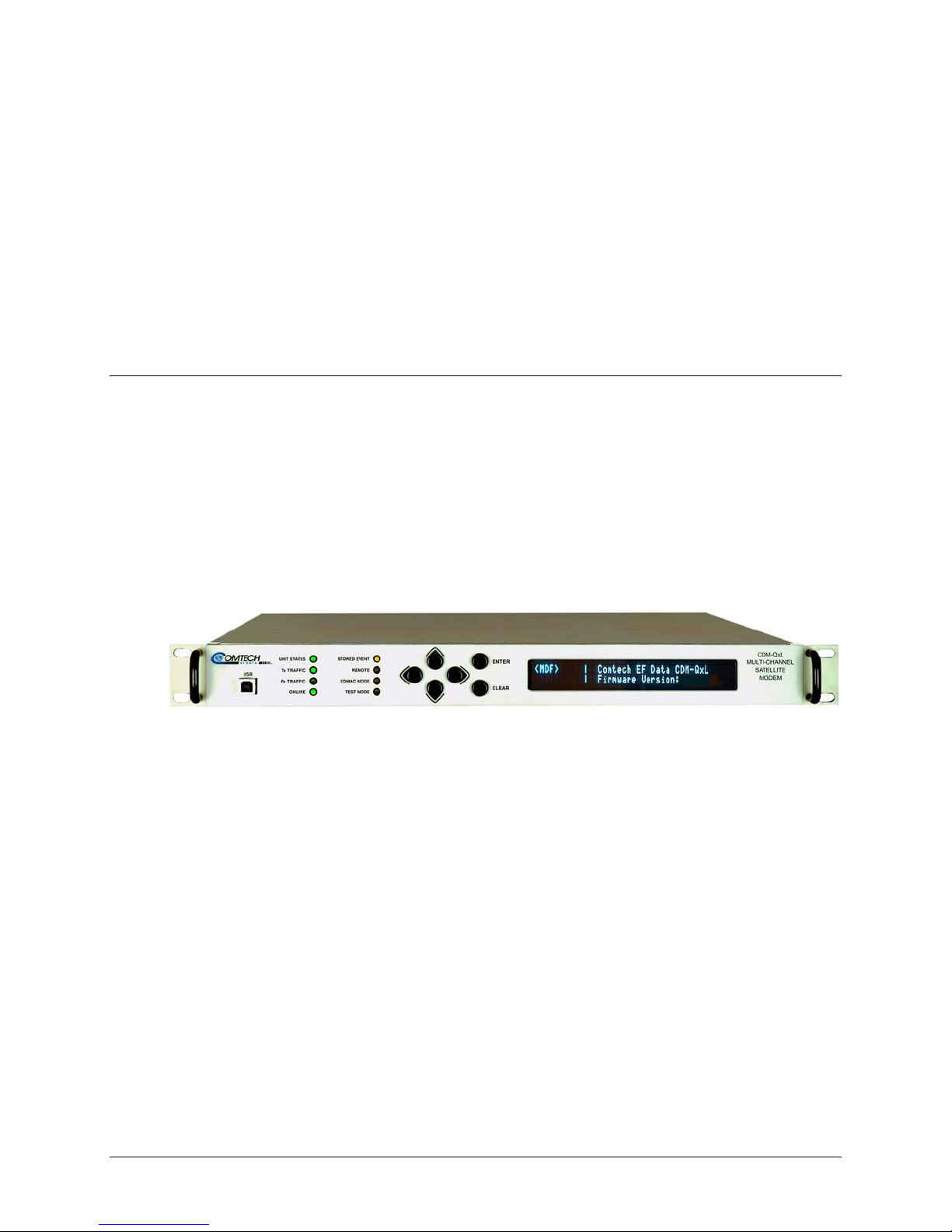
Figure 1-1. CDM-Qx/QxL Multi-Channel Satellite Modem (CDM-QxL shown) ................................... 1–1
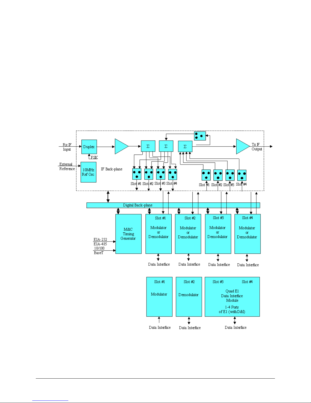
Figure 1-2. CDM-Qx/QxL Open Network Satellite Modem Block Diagrams ......................................... 1–4
Figure 1-3. CDM-Qx/QxL Dimensional Envelope ................................................................................... 1–6
Figure 1-4. Front Panel View (CDM-Qx shown) ..................................................................................... 1–6
Figure 1-5. CDM-Qx/QxL Rear Panel View ............................................................................................ 1–7
Figure 1-6. Power Spectral Density Chart ............................................................................................. 1–15
Figure 2-1. Installation of Optional Rear-Mounting Support Brackets .................................................... 2–3
Figure 2-2. Installation of Optional Side-Railings (FP/SL0006) ............................................................. 2–4
Figure 3-1. CDM-Qx/QxL Rear Panel Configuration Examples .............................................................. 3–1
Figure 3-2. HSSI Interface Block Diagram ............................................................................................ 3–10
Figure 3-3. HSSI Interface Example ....................................................................................................... 3–11
Figure 4-1. Flash Update via Internet ....................................................................................................... 4–1
Figure 5-1. CDM-Qx/QxL – Front Panel View ........................................................................................ 5–1
Figure 5-2. CDM-Qx/QxL Keypad ........................................................................................................... 5–3
Figure 5-3. Loopback .............................................................................................................................. 5–51
Figure 6-1. CDM-Qx/QxL Multi-Channel Satellite Modem Home page ................................................. 6–8
Figure 6-2. Home | Contact Information page .......................................................................................... 6–9
xii

CDM-Qx/QxL Multi-Channel Satellite Modem with DoubleTalk™ Carrier-in-Carrier® Revision 7
Table of Contents MN/CDMQX.IOM
Figure 6-3. Home | Customer Support page ............................................................................................ 6–10
Figure 6-4. Admin | Access page ............................................................................................................ 6–11
Figure 6-5. Admin | Remote page ........................................................................................................... 6–13
Figure 6-6. Config Mdm | Quick View Page Example ........................................................................... 6–14
Figure 6-7. Configuration Icon Group Examples ................................................................................... 6–15
Figure 6-8. ‘Config Mdm | Quick View | Config’ Nested Pages – Base, Tx .......................................... 6–16
Figure 6-9. ‘Config Mdm | Quick View | Config’ Nested Pages – Rx, MD ........................................... 6–17
Figure 6-10. ‘Config Mdm | Quick View | Status’ Nested Pages – Base, Tx ......................................... 6–20
Figure 6-11. ‘Config Mdm | Quick View | Status’ Nested Pages – Rx, MD .......................................... 6–21
Figure 6-12. ‘Config Mdm | Quick View | Test’ Nested Pages – Base, Tx ............................................ 6–24
Figure 6-13. ‘Config Mdm | Quick View | Test’ Nested Pages – Rx, MD ............................................. 6–25
Figure 6-14. Nested Test Page with Spectrum Analyzer Mode ‘On’ – Rx, MD .................................... 6–27
Figure 6-15. ‘Config Mdm | Quick View | Utility’ Nested Pages – Base, Tx ......................................... 6–28
Figure 6-16. ‘Config Mdm | Quick View | Utility’ Nested Pages – Rx, MD .......................................... 6–29
Figure 6-17. Config Mdm | Unit Status Page .......................................................................................... 6–33
Figure 6-18. ODU | BUC page ................................................................................................................ 6–34
Figure 6-19. ODU | LNB page ................................................................................................................ 6–35
Figure 6-20. Maint | Unit Info page ........................................................................................................ 6–36
Figure 6-1. Viterbi Decoding .................................................................................................................... 7–8
Figure 6-2. Viterbi with Concatenated R-S Outer Code ........................................................................... 7–9
Figure 6-3. 8-PSK/TCM Rate 2/3 with and without concatenated R-S Outer Code .............................. 7–10
Figure 6-4. Comtech EF Data Turbo Product Codec Rate 3/4 QPSK, 8-PSK and 16-QAM ................. 7–11
Figure 6-5. Comtech EF Data Turbo Product Codec Rate 7/8 QPSK, 8-PSK and 16-QAM ................. 7–12
Figure 6-6. Rate 1/2 QPSK, Rate 17/18 QPSK and Rate 17/18 8-PSK .................................................. 7–13
Figure 6-7. Rate 21/44 BPSK and Rate 5/16 BPSK Turbo ..................................................................... 7–14
Figure 6-8. 16-QAM Viterbi, Rate 3/4 and Rate 7/8 with 220,200 R-S Outer Code .............................. 7–15
Figure 9-1. Traditional FDMA System (without CnC) ............................................................................. 9–2
Figure 9-2. Same System Using CDM-Qx/QxL and DoubleTalk
Carrier-in-Carrier ............................... 9–2
Figure 9-3. Adjacent Carrier: Case A (As Tested) and Case B (As Plotted) ............................................ 9–5
Figure 9- 4 . QP S K 3/ 4 T ur b o d egradati o n v e rsus relati v e c ar r i e r s pa c in g ( f o r two adjacent c a r r ie r s ) ......... 9–6
Figure 9- 5 . 8- P S K 3/ 4 T ur bo d e g radation ve r s us r e lative car r ie r s pa c i n g ( f o r t w o a djacent car r i e r s) ......... 9–6
Figure 9- 6 . 1 6- Q A M 3/ 4 T ur b o d e gr a dation vers us r e l at i v e carrier spa c i n g (f o r t w o a d ja c e n t ca r r iers) ..... 9–6
Figure 9-7. Adjacent Carrier Cases ........................................................................................................... 9–7
Figure 9-8. CnC Ratio ............................................................................................................................... 9–8
Figure 9-9. CnC Ratio For QPSK and 8-PSK ........................................................................................... 9–9
Figure 9-10. CnC Ratio For 16-QAM ....................................................................................................... 9–9
Figure 9-11. CnC Example ..................................................................................................................... 9–10
Figure 9-12. Link With Fading At Site ‘A’ ............................................................................................ 9–11
Figure 9-13. Asymmetric Link (Same Data Rate, Different Antennas) .................................................. 9–12
Figure 11-1. CDM-Qx/QxL Chassis Rear Panel Schematic ................................................................... 11–1
Figure A-1. : EIA-530 to RS-422/449 DCE Conversion Cable (CA/WR0049) ...................................... A-2
Figure A-2. : EIA-530 to V.35 DCE Conversion Cable (CA/WR0059) .................................................. A-3
Figure A-3. EIA-530 DCE Conversion Cable (CA/WR9718-1) ............................................................. A-4
Figure A-4. Switch Programming Cable .................................................................................................. A-5
xiii

CDM-Qx/QxL Multi-Channel Satellite Modem with DoubleTalk™ Carrier-in-Carrier® Revision 7
Table of Contents MN/CDMQX.IOM
This page is intentionally blank.
xiv

About this Manual
PREFACE
This manual provides installation and operation information for the Comtech EF Data CDM-Qx
Multi-Channel Modem with DoubleTalk™ Carrier-in-Carrier
intended for earth station engineers, technicians, and operators responsible for the operation and
maintenance of the 70-140 MHz CDM-Qx and its L-Band counterpart, the CDM-QxL.
Revision 7 denotes a complete rewrite of the CDM-Qx Multi-Channel Satellite Mo dem Installation
and Operation Manual (CEFD P/N MN/C DMQX.IO M). It is intend ed replace al l previous version s
of this document in their entirety. All content has been reorganized and updated to conform to
current Comtech EF Data Technical Publications Standards and Practices.
®
. This is a technical document
Reporting Comments or Suggestions Concerning this Manual
Comments and suggestions regarding the content and design of this manual will be appreciated.
To submit comments, please contact the Comtech EF Data Technical Publications Department:
TechnicalPublications@comtechefdata.com
.
Conventions and References
Metric Conversion
Metric conversion information is located on the inside back cover of this manual. This information
is provided to assist the operator in cross-referencing non-metric to metric conversions.
xv
CDM-Qx Multi-Channel Satellite Modem with DoubleTalk Carrier-in-Carri er Revision 7
Preface MN/CDMQX.IOM
Cautions and Warnings
WARNING indicates a potentially hazardous situation that, if not avoided, could
result in death or serious injury.
CAUTION indicates a hazardous situation that, if not avoided, may result in minor
or moderate injury. CAUTION may also be used to indicate other unsafe practices
or risks of property damage.
IMPORTANT or NOTE indicates information critical for proper equipment function.
Recommended Standard Designations
Recommended Standard (RS) Designations have been superseded by the new designation of the
Electronic Industries Association (EIA). References to the old designations are shown only when
depicting actual text displayed on the screen of the unit (RS-232, RS-485, etc.). All other references
in the manual will be shown with the EIA designations.
Trademarks
Carrier-in-Carrier is a registered trademark of Comtech EF Data Corporation. DoubleTalk is a
trademark of Applied Signal Technology, Inc. Windows is a trademark of the Microsoft
Corporation. Other product names mentioned in this manual may be trademarks or registered
trademarks of their respective companies and are hereby acknowledged.
The user should carefully review the following information:
IMPORTANT
Electrical Safety
The CDM-Qx/QxL Multi-Channel Satellite Mod em has been shown to comply with safety standard
EN60950: Safety of Information Technology Equipment, including Electrical Business
Machines.
Observe the following: The CDM-Qx (70/140 MHz) is rated for operation over the range 100 to
240 VAC. It has a maximum power consumption of 120 watts, and draws a maximum of 1 amp.
The CDM-QxL (L-Band) is rated for operation over the range 100 to 240 VAC. It has a maximum
power consumption of 250 watts, and draws a maximum of 2 amps.
Fuses
FOR CONTINUED OPERATOR SAFETY, ALWAYS REPLACE THE FUSES WITH
CAUTION
THE CORRECT TYPE AND RATING.
xvi

CDM-Qx Multi-Channel Satellite Modem with DoubleTalk Carrier-in-Carri er Revision 7
Preface MN/CDMQX.IOM
AC Operation: The AC-powered CDM-Qx/QxL is fitted with two fuses – one each for line and
neutral connections. These are contained within the body of the IEC power inlet connector, behind a
small plastic flap.
For the CDM-Qx:
• For 115 and 230 VAC operation, use 2.0A, slow-blow 20mm fuses.
For the CDM-QxL:
• For 115 and 230 VAC operation, use T3.15A, slow-blow 20mm fuses.
DC Operation: The DC-powered CDM-Qx/QxL is fitted with one fuse for positive connection.
Thid fuse is contained within the body of the power inlet, behind a small plastic flap.
For the CDM-Qx:
• For 38 to 60 VDC operation, use X.XA, 20mm fuses.
For the CDM-QxL:
• For 38 to 60 VDC operation if the modem has no BUC power supply, use T3.15A,
slow-blow 20mm fuses
• For 38 to 60 VDC operation if the modem is fitted with internal BUC power supply,
use T8.0A, slow-blow 20mm fuses.
Environmental
The CDM-Qx/QxL must not be operated in an environment where the unit is exposed to extremes
of temperature outside the ambient range 0 to 50°C (32° to 122°F); precipitation, condensation, or
humid atmospheres above 95% RH; altitudes (non-pressurized) greater than 2000 meters;
excessive dust or vibration; flammable gases, corrosive or explosive atmospheres.
Operation in vehicles or other transportable installations that are equipped to provide a stable
environment is permitted. If such vehicles do not provide a stable environment, safety of the
equipment to EN60950 may not be guaranteed.
Installation
Do not plug in the modulator and demodulator cards while the modem
CAUTION
The CDM-Qx/QxL is shipped with a line inlet cable suitable for use in the country of operation.
If it is necessary to replace this cable, ensure the replacement has an equivalent specification.
Examples of acceptable ratings for the cable include HAR, BASEC and HOXXX-X. Examples of
acceptable connector ratings include VDE, NF-USE, UL, CSA, OVE, CEBEC, NEMKO,
DEMKO, BS1636A, BSI, SETI, IMQ, KEMA-KEUR and SEV.
is powered on. Damage to the cards may result.
xvii
CDM-Qx Multi-Channel Satellite Modem with DoubleTalk Carrier-in-Carri er Revision 7
Preface MN/CDMQX.IOM
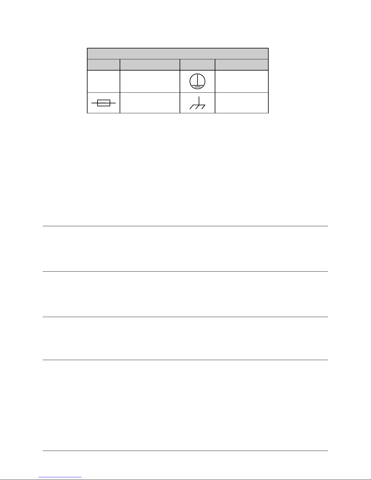
International Symbols
Symbol Definition Symbol Definition
~
CDM-Qx/QxL AC Modem Installation: The installation and connection to the line supply must
be made in compliance to local or national wiring codes and regulations. The CDM-Qx/QxL is
designed for connection to a power system that has separate ground, line and neutral conductors.
The equipment is not designed for connection to a power system that has no direct connection to
ground.
CDM-Qx/QxL DC Modem Installation: The CDM-Qx/QxL DC input is connected to a nominal
48 VDC prime power source. The DC input is isolated from the chass is and from the DC output to
the BUC if equipped with internal BUC power supply. The chassis may be connected to a local
system ground using a separate wire to the ground stud on the back of the ch assis. Since the DC
input is isolated, either the positive or the negativ e side of the DC input may be common with local
ground. Labeling on the chassis rear panel indicates the positive and negative terminals of the input
power socket.
Alternating Current
Fuse
Protective Earth
Chassis Ground
Telecommunications Terminal Equipment Directive
In accordance with the Telecommunications Terminal Equipment Directive 91/263/EEC, this
equipment should not be directly connected to the Public Telecommunications Network.
CE Mark
Comtech EF Data declares that the CDM-Qx/QxL Multi-Channel Satellite Modem meets the
necessary requirements for the CE Mark.
RoHS Compliancy
This unit satisfies (with exemptions) the requirements specified in the European Union Directive on
the Restriction of Hazardous Substances, Directive 2002/95/EC, (EU RoHS).
EMC (Electromagnetic Compatibility)
In accordance with European Directive 89/336/EEC, the CDM-Qx/QxL Modem has been shown,
by independent testing, to comply with the following standards:
Emissions: EN 55022 Class B - Limits and methods of measurement of radio
interference characteristics of Information Technology Equipment.
(Also tested to FCC Part 15 Class B)
xviii

CDM-Qx Multi-Channel Satellite Modem with DoubleTalk Carrier-in-Carri er Revision 7
Preface MN/CDMQX.IOM
Immunity: EN 50082 Part 1 - Generic immunity standard, Part 1: Domestic,
commercial and light industrial environment.
Additionally, the CDM-Qx/QxL has been shown to comply with the following standards:
EN 61000-3-2 Harmonic Currents Emission
EN 61000-3-3 Voltage Fluctuations and Flicker
EN 61000-4-2 ESD Immunity
EN 61000-4-4 EFT Burst Immunity
EN 61000-4-5 Surge Immunity
EN 61000-4-6 RF Conducted Immunity
EN 61000-4-8 Power frequency Magnetic Field Immunity
EN 61000-4-9 Pulse Magnetic Field Immunity
EN 61000-4-11 Voltage Dips, Interruptions, and Variations Immunity
EN 61000-4-13 Immunity to Harmonics
To ensure that the Modem continues to comply with these standards,
IMPORTANT
observe the following instructions:
• Connections to the transmit and receive IF ports (Type ‘BNC’ female connectors for the
CDM-Qx, Type ‘N’ female connectors for the CDM-QxL) should be made using a good
quality coaxial cable; e.g., RG58/U (50Ω) or RG59/U (75Ω).
• All 'D' type connectors attached to the rear panel must have back-shells that provide
continuous metallic shielding. Cable with a continuous outer shield (either foil or braid,
or both) must be used, and the shield must be bonded to the back-shell.
• The equipment must be operated with its cover on at all times. If it becomes necessary to
remove the cover, the user should ensure that the cover is correctly re-fitted before
normal operation commences.
xix

CDM-Qx Multi-Channel Satellite Modem with DoubleTalk Carrier-in-Carri er Revision 7
Preface MN/CDMQX.IOM
Warrant y Policy
Comtech EF Data products are warranted against defects in material and workmanship
for a specific period from the date of shipment, and this period varies by product. In
most cases, the warranty period is two years. During the warranty period, Comtech EF
Data will, at its option, repair or replace products that prove to be defective. Repairs are
warranted for the remainder of the original warranty or a 90 day extended warranty,
whichever is longer. Contact Comtech EF Data for the warranty period specific to the
product purchased.
For equipment under warranty, the owner is responsible for freight to Comtech EF Data
and all related customs, taxes, tariffs, insurance, etc. Comtech EF Data is responsible for
the freight charges only for return of the equipment from the factory to the owner.
Comtech EF Data will return the equipment by the same method (i.e., Air, Express,
Surface) as the equipment was sent to Comtech EF Data.
All equipment returned for warranty repair must have a valid RMA number issued prior
to return and be marked clearly on the return packaging. Comtech EF Data strongly
recommends all equipment be returned in its original packaging.
Comtech EF Data Corporation’s obligations under this warranty are limited to repair or
replacement of failed parts, and the return shipment to the buyer of the repaired or
replaced parts.
Limitations of Warranty
The warranty does not apply to any part of a product that has been installed, altered,
repaired, or misused in any way that, in the opinion of Comtech EF Data Corporation,
would affect the reliability or detracts from the performance of any part of the product, or
is damaged as the result of use in a way or with equipment that had not been previously
approved by Comtech EF Data Corporation.
The warranty does not apply to any product or parts thereof where the serial number or the
serial number of any of its parts has been altered, defaced, or removed.
The warranty does not cover damage or loss incurred in transportation of the product.
The warranty does not cover replacement or repair necessitated by loss or damage from
any cause beyond the control of Comtech EF Data Corporation, such as lightning or other
natural and weather related events or wartime environments.
The warranty does not cover any labor involved in the removal and or reinstallation of
warranted equipment or parts on site, or any labor required to diagnose the necessity for
repair or replacement.
The warranty excludes any responsibility by Comtech EF Data Corporation for incidental
or consequential damages arising from the use of the equipment or products, or for any
xx

CDM-Qx Multi-Channel Satellite Modem with DoubleTalk Carrier-in-Carri er Revision 7
Preface MN/CDMQX.IOM
inability to use them either separate from or in combination with any other equipment or
products.
A fixed charge established for each product will be imposed for all equipment returned
for warranty repair where Comtech EF Data Corporation cannot identify the cause of the
reported failure.
Exclusive Remedies
Comtech EF Data Corporation’s warranty, as stated is in lieu of all other warranties,
expressed, implied, or statutory, including those of merchantability and fitness for a
particular purpose. The buyer shall pass on to any purchaser, lessee, or other user of
Comtech EF Data Corporation’s products, the aforementioned warranty, and shall
indemnify and hold harmless Comtech EF Data Corporation from any claims or liability
of such purchaser, lessee, or user based upon allegations that the buyer, its agents, or
employees have made additional warranties or representations as to product preference or
use.
The remedies provided herein are the buyer’s sole and exclusive remedies. Comtech EF
Data shall not be liable for any direct, indirect, special, incidental, or consequential
damages, whether based on contract, tort, or any other legal theory.
xxi

CDM-Qx Multi-Channel Satellite Modem with DoubleTalk Carrier-in-Carri er Revision 7
Preface MN/CDMQX.IOM
Customer Support
Refer to p. xx in this Preface for information regarding this product’s Warranty Policy.
Contact the Comtech EF Data Customer Support Department for:
• Product support or training
• Reporting comments or suggestions concerning manuals
• Information on upgrading or returning a product
A Customer Support representative may be reached at:
Comtech EF Data
Attention: Customer Support Department
2114 West 7th Street
Tempe, Arizona 85281 USA
480.333.2200 (Main Comtech EF Data number)
480.333.4357 (Customer Support Desk)
480.333.2161 FAX
To return a Comtech EF Data product (in-warranty and out-of-warranty) for repair or
replacement:
• Contact the Comtech EF Data Customer Support Department. Be prep ared to supply the
Customer Support representative with the model number, serial number, and a description
of the problem.
• Request a Return Material Authorization (RMA) number from the Comtech EF Data
Customer Support representative.
• Pack the product in its original shippin g carton/packaging to ensure that th e product is not
damaged during shipping.
• Ship the product back to Comtech EF Data. (Shipping charges should be prepaid.)
Online Customer Support
An RMA number request can be requested electronically by contacting the Customer Support
Department through the online support page at www.comtechefdata.com/support.asp
• Click on “Service” for detailed instructions on our return procedures.
• Click on the “RMA Request Form” hyperlink, then fill out the form completely before
sending.
• Send e-mail to the Customer Support Department at service@comtechefdata.com.
:
xxii
1.1 Overview
The CDM-Qx/QxL Multi-Channel Satellite Modem with DoubleTalk™ Carrier-in-Carrier® is a
modular multi-channel modem with redundancy contained in a single rack unit (1RU) chassis.
The CDM-Qx/QxL offers flexibility, redundancy, integration, and performance with four slots
configurable as modulators or demodulators. The CDM-Qx operates on the 70/140 MHz IF
frequency, while the CDM-QxL (Figure 1-1) is the L-Band (950
same modem.
The CDM-Qx/QxL supports DoubleTalk™ Carrier-in-Carrier
and receive (Rx) carriers in a full-duplex link to use the same transponder segment.
Chapter 1. INTRODUCTION
MHz – 1950MHz) version of the
®
option, allowing transmit (Tx)
Figure 1-1. CDM-Qx/QxL Multi-Channel Satellite Modem (CDM-QxL shown)
1.1.1 Standard and Optional Features
The CDM-Qx/QxL includes, but is not limited to, the following features:
®
• DoubleTalk™ Carrier-in-Carrier
the same transponder segment;
• CDM-Qx: 50 to 90 and 100 to 180 MHz frequency range;
• CDM-QxL: 950 MHz-1950 MHz L-band;
• 32 kbps to 20 Mbps;
• BPSK, QPSK, 8-PSK, 16-QAM operation;
• Flexible Configuration:
o 1 modem or 2 modems configured as 1:1
o Up to 4 demodulators
• Optional Built In Redundancy:
o 1:1 modem
allowing Tx and Rx carriers of a full-duplex link to use
1–1

CDM-Qx/QxL Multi-Channel Satellite Modem with DoubleTalk™ Carrier-in-Carrier® Revision 7
Introduction MN/CDMQx.IOM
o Up to 1:3 modulator
o Up to 1:3 demodulator
• EIA-422/-530, V.35, G.703 (T1/E1/E2) and HSSI Interfaces;
• 1 to 4 Ports of G.703 (E1 with D&I ) Quad E1 Interface Card;
• 10/100 BaseT Ethernet, RS-232 or RS-485 for M&C remote control;
• Forward Error Correction (FEC) choices included:
o Viterbi
o Viterbi with Reed-Solomon
o Trellis and Reed-Solomon
o Optional, 2
nd
Generation Turbo Product Coding (TPC) (IESS-315 compliant)
• Fully Accessible System Topology (FAST);
• Asymmetric Loop Timing;
• Common frequency reference for all modules;
• Optional High Stability Reference;
• Optional Redundant Power Supply;
• Individual or summed Modulator output power control;
• Interoperable with: CDM-550T, -570L, -600, -600L, SDM-300A, -300L3, and -8000
modems (in compatible modes);
• Drop and Insert, closed network version;
• Embedded Distant-end Monitor and Control (EDMAC) (see Note)
• Automatic Uplink Power Control (AUPC)
Refer to Sect. 1.3 for in-depth product information and Sect. 1.5 for the CDM-Qx/QxL Summary of
Specifications.
1.1.2 DoubleTalk™ Carrier-in-Carrier®
Designed for bandwidth compression, Carrier-in-Carrier® is based on Applied Signal
Technology’s DoubleTalk™ which uses “Adaptive Cancellation,” a patented (United States
Patent #6,859,641) technology that allows full duplex satellite links to transmit concurrently in
the same segment of transponder bandwidth. Available as an option to the modem, this added
dimension can result in a significant improvement in satellite transponder utilization.
1.1.3 Turbo Product Coding
The CDM-Qx/QxL offers optional 2nd generation Turbo Product Codec (TPC). TPC
simultaneously offers increased coding gain, lower decoding delay, and significant bandwidth
savings. The TPC provides:
• BPSK 5/16 and 21/44
• QPSK 21/44, 3/4, 7/8 and 17/18
• 8-PSK 3/4, 7/8, and 17/18
• 16QAM 3/4 and 7/8
1–2

CDM-Qx/QxL Multi-Channel Satellite Modem with DoubleTalk™ Carrier-in-Carrier® Revision 7
Introduction MN/CDMQx.IOM
1.2 Functional Description
The CDM-Qx/QxL Multi-Channel Satellite Modem has two fundamentally different types of
interface – IF and Data:
• The Data interface can be a bi-directional path, which connects with the customer’s
equipment (assumed to be the DTE) and the modem (assumed to be the DCE).
• The IF interface provides a bi-direction al link with th e satellit e vi a th e upl ink and downlin k
equipment.
Transmit data is received by the terrestrial interface where line receivers convert the clock and
data signals to CMOS levels for further processing. A small FIFO follows the terrestrial interface
to facilitate the various clocking and framing options. If framing is enabled, the transmit clock
and data output from the FIFO pass through the framer, where the overhead EDMAC data is
added to the main data. Otherwise, the clock and data are passed directly to the Forward Error
Correction encoder.
In the FEC encoder, the data is scrambled, differentially encoded, and then convolutionally
encoded. Following the encoder, the data is fed to the transmit digital filters, which perform spectral
shaping on the data signals. The re sultant I and Q signals are th en fed to the BPSK/QPSK/8 -PSK/
16-QAM modulator. The carrier is generated by a frequency synthesizer, a nd the I and Q signals
directly modulate this carrier to produce an IF output signal.
The RX IF signal is translated and filt ered at an intermediate frequency (IF) u sing the coarse step
synthesizer. This is mixed with a second synthesizer, resulting in the signal being IF sampled with a
high-speed analog to digital converter (A to D). The sampled IF i s then digitally split into an Inphase (I) and a Quadrature (Q) component. An AGC circuit keeps the desi red signal level cons tant
over a broad range of input levels. The I and Q signals are then decimated to reduce the
computation rate into the poly phase matched filter.
Carrier and clock recovery is performed on the baseband I and Q signals after the matched filter.
The resultant demodulated signal is fed, in soft decision form, to the selected FEC decoder
(which can be Viterbi, TCM, Reed-Solomon, or Turbo if installed). After decoding, the recovered
clock and data pass to the de-framer (if EDMAC framing is enabled) where the overhead
information is removed. Following this, the data passes to the Plesiochronous/Doppler buffer,
which has a programmable size, or alternatively bypasses the buffer. From here, the receive clock
and data signals are routed to the terrestrial interface, and are passed to the externally connected
DTE equipment.
Physically, a modem chassis is comprised of three main card assemblies:
• The IF Backplan e car d includes the frequency reference, power splitters, power summers,
the FSK link (L-Band version only) and the IF Loop back functions.
• The Digital Backplane card routes all the con trol signals, data p ath switching, Carrier-in-
Carrier
®
signals and power for all modules.
• The M&C controls all functions in the unit.
Within the chassis are four slots which allow any combination of modulators or demodulators to be
installed. If configured as a single modem, two plug-in cards comprising a modulator and
demodulator are required.
• A Modulator card contains the transmit interface circuits, the framer, the encoder or
encoders and the signal processing functions of modulation.
1–3
CDM-Qx/QxL Multi-Channel Satellite Modem with DoubleTalk™ Carrier-in-Carrier® Revision 7
Introduction MN/CDMQx.IOM
• A Demodulator card performs all of the signal processing functions of carrier search,
cancellation, demodulation, Forward Error Correction, the de-framer, plesiochronous/
Doppler buffer and the receive interface circuits.
• Terrestrial data interface cards can be on the modulator cards or demodulator cards.
When a modulator and demodulator are grouped togeth er, the data interface card can be
used for full-duplex data interface. When one or up to four ports of E1 (with D&I) are
needed, the Quad E1 Data Interface Module can be installed in Slots 3 and 4.
Figure 1-2
shows a functional block diagram of the modem with either modulators and
demodulators in all four slots; and the figure also shows a modulator in Slot 1 and a demodulator in
Slot 2 along with a Quad E1 Data Interface Module in Slots 3 and 4.
Figure 1-2. CDM-Qx/QxL Open Network Satellite Modem Block Diagrams
1–4

CDM-Qx/QxL Multi-Channel Satellite Modem with DoubleTalk™ Carrier-in-Carrier® Revision 7
Introduction MN/CDMQx.IOM
1.3 Features
1.3.1 Physical Description
CDM-Qx/QxL Multi-Channel Sa tellite Modem is constructed as a 1RU-high rack-mounting chassis,
which can be free-standing if desired. Rack handles at the front facilitate removal from and placement
into a rack.
1.3.2 Compatibility
The CDM-Qx/QxL is backwards compatible with a number of Comtech EF Data CDM, SDM,
and
SLM modems.
1.3.3 Major Assemblies
CDM-Qx Major Assemblies
Assembly Description
PL/10570-1 1 PPM Reference IF Backplane 70/140 MHz IF
PL/10570-2 0.1 PPM Reference IF Backplane 70/140 MHz IF
PL/10069 Digital Backplane
PL/10073 Monitor and Control Card
PL/11128 70/140 MHz IF Modulator
PL/10635
PL/12960-1 AC Chassis, 70/140 IF
PL/12960-2 DC Chassis, 70/140 IF
Assembly Description
PL/10070-1 0.1 PPM Reference IF Backplane L-Band IF
PL/10069 Digital Backplane
PL/10073 Monitor and Control Card
PL/10071 L-Band IF Modulator
PL/10072
PL/12798-1 AC Chassis, L-Band
PL/12798-2 DC Chassis, L-Band
Assembly Description
AS/11014 Turbo Codec – Simplex
PL/10678 EIA-530 Duplex Data interface
PL/10697 G.703 Balanced Duplex Data Interface
PL/10698 G.703 Unbalanced Duplex Data Interface (E1/T1)
PL/10635 G.703 Unbalanced Duplex Data Interface (E2)
PL/12608-1 Quad E1 G.703 Data Interface
PL/10898-1 EIA-612/613 HSSI Interface
70/140 MHz IF Demodulator with Carrier in Carrier®
CDM-QxL Major Assemblies
L-Band IF Demodulator with Carrier in Carrier®
CDM Qx/QxL Optional Assemblies
1–5
CDM-Qx/QxL Multi-Channel Satellite Modem with DoubleTalk™ Carrier-in-Carrier® Revision 7
Introduction MN/CDMQx.IOM
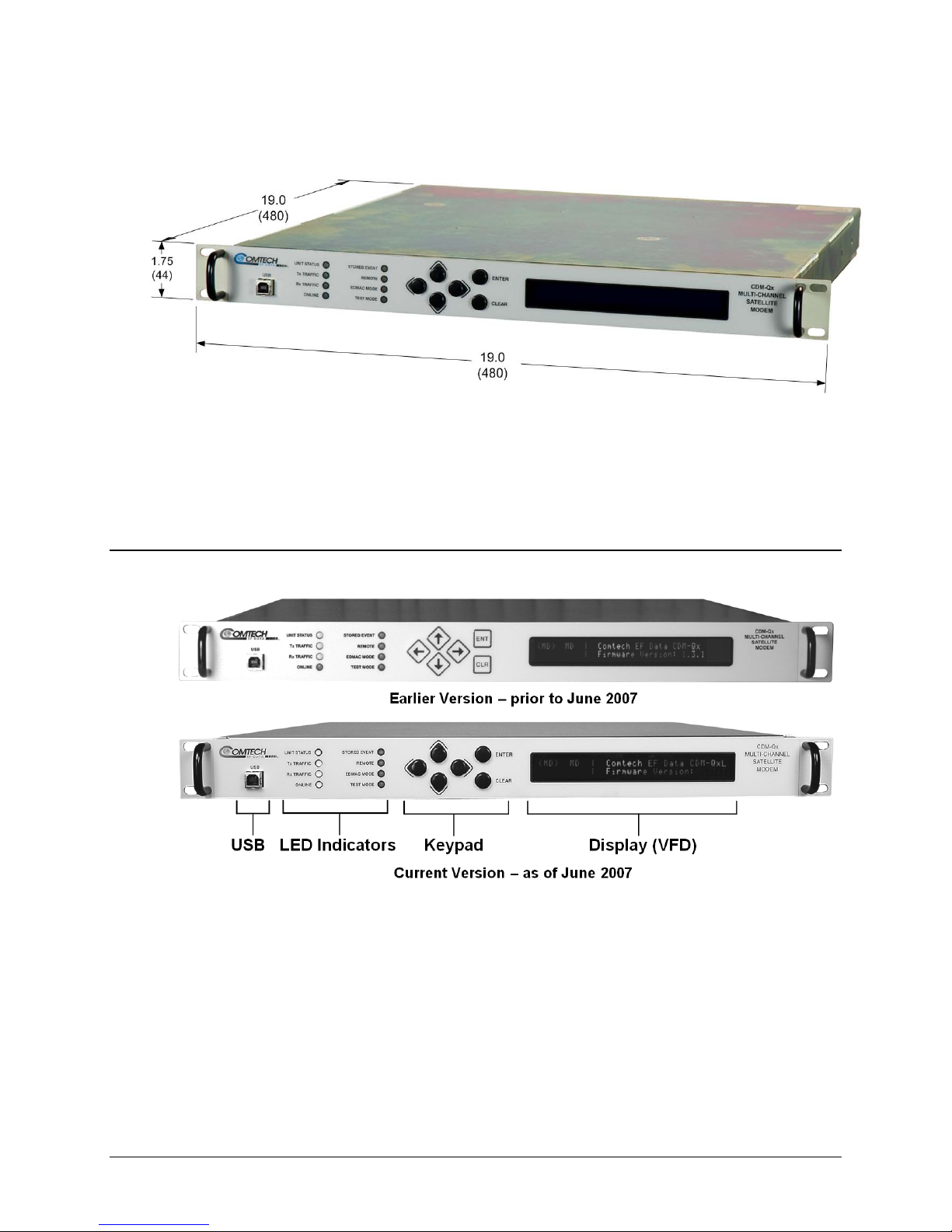
1.3.4 Dimensional Envelope
Figure 1-3. CDM-Qx/QxL Dimensional Envelope
1.3.5 Physical Features
1.3.5.1 Front Panel
Figure 1-4 shows the fro
front panel features (from left), a USB port; eight Light-Emitting-Diode (LED) indicators; a
keypad; and a Vacuum Fluorescent Display (VFD):
• The USB port is a slave connector used to reflash the unit’s firmware. For more
information, refer to Chapter 4. FLASH UPGRADING.
• The LEDs indicate, in a summary fashion, the status of the unit.
• The keypad comprises six individual keyswitches. They have a positive ‘click’ action,
which provides tactile feedback. The user enters data via the keypad, and messages are
displayed on the VFD.
Figure 1-4. Front Panel View (CDM-Qx shown)
nt panel of the CDM-Qx/QxL Open Network Satellite Modem. The
1–6

CDM-Qx/QxL Multi-Channel Satellite Modem with DoubleTalk™ Carrier-in-Carrier® Revision 7
Introduction MN/CDMQx.IOM
Note: As shown in Figure 1-4, units manufactured prior to June 2007 featured six
individual keyswitches mounted behind a fully sealed membrane overlay.
These six switches are identified (in Current Keypad [Earlier Keypad] format) as S [↑],
T [↓], W [←], X [→],
ENTER [ENT], and CLEAR [CLR].
• The VFD is an active display showing two lines of 40 characters each. It produces a blue
light with adjustable brightness. Compared to a Liquid Crystal Display (LCD), the VFD
has greatly superior viewing characteristics and does not suffer problems of viewing
angle or contrast.
The function and behavior of the LED indicators, keypad, and VFD is described in detail in
Chapter 5. FRONT PANEL OPERATION.
1.3.5.2 Rear Panel
Figure 1-5 shows the connectors installed in the rear panel of the CDM-Qx/QxL Multi-Channel
Satellite Modem. As outlined in A CDM-Qx/QxL base chassis features two IF connectors and
three Utility connectors that are typical for all operation. Additionally, an Alarms connector, not
part of the base chassis but included in this table for reference only, is provided with every
available data interface module.
External cables are attached to these connectors. For detailed information about the connectors
outlined in Table 1-1,
plus the connectors unique to each date interface module, see Chapter 3.
REAR PANEL CONNECTORS.
CDM-Qx (70/140 MHz) DC Unit
CDM-QxL (L-Band) AC Unit
Figure 1-5. CDM-Qx/QxL Rear Panel View
1–7
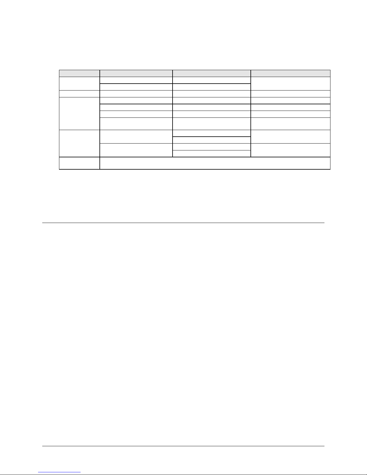
CDM-Qx/QxL Multi-Channel Satellite Modem with DoubleTalk™ Carrier-in-Carrier® Revision 7
A
–
-Qx
Introduction MN/CDMQx.IOM
Table 1-1. CDM-Qx/QxL Rear Panel Connectors – Base Chassis
Connector Group Connector Name
Power (Sect. 3.2.1) AC See Sect. 3.5.1
DC (optional, CDM-QxL only)
Ground (Sect. 3.2.2) #10-32 stud
Utility
(Sects. 3.2.3, 3.2.4,
3.2.6, 3.3.1)
IF (Sect. 3.2.5)
Terrestrial Data
(Sect. 3.3)
M&C 10/100 (Sect. 3.2.3) RJ-45
485/232 (Sect 3.2.4) 9-pin Type ‘D’ female
Ref (Sect 3.2.6) BNC 50Ω female
larms (not p/o base chassis
for each data interface) (Sect. 3.3.1)
Rx
Tx
Connectors vary dependant on the installed data interface (G.703 Bal, G.703 Unbal, EIA-530, Quad E1, or HSSI) module.
See Sect. 3.3.x for complete information about the connectors associated with these interfaces.
See Sect. 3.5.2
typical
15-pin Type ‘D’ male Form C Alarms (relay closures)
CDM-Qx:
CDM-QxL:
CDM
:
CDM-QxL:
Note: The European EMC Directive (EN55022, EN50082-1) requires using properly shielded cables for DATA
I/O. These cables must be double-shielded from end -to-end , ensu ring a con tinuous grou nd shield .
1.3.6 Hardware Options
1.3.6.1 CDM-Qx/QxL Hardware Options
There are four hardware options available:
Connector Type
BNC female (70/140MHz band)
Type ’N’ female (L-Band)
BNC female (70/140MHz band)
Type ’N’ female (L-Band)
Function
Chassis power
Common Chassis Ground
10/100 BaseT Remote Interface
EIA Remote Interface
External reference for modem synthesizers
IF Input
IF Output
• The first hardware option, Comtech EF Data’s Turbo Product Codec (TPC), represents
a very significant development in the area of Forward Error Correction (FEC). It provides
one of the best FEC technologies currently available, and is now offered with a sufficient
range of code rates and modulation types to optimize link performance under any
conditions.
Turbo Product Codec consists of a plug-in daughter card (SIMM module) that is field
upgradeable. The TPC option provides data rate capability up to 20 Mbps, with the
following code rates:
o Rate 5/16 (BPSK)
o Rate 21/44 (BPSK, QPSK)
o Rate 3/4 (QPSK, 8-PSK, and 16-QAM)
o Rate 7/8 (QPSK, 8-PSK, and 16-QAM)
o Rate 17/18 (QPSK, 8-PSK)
• The second hardware option is the Internal Reference Stability. The high stability
option includes a 6 x 10
the low stability option has a 1 x 10
-8
10 MHz reference oscillator on the IF Backplane board, while
-6
10 MHz reference on the IF Backplane board. This
option must be configured in the factory at the time of order.
• The third hardware option is the IF Impedance and Connectors. The IF may be
configured with either BNC female connectors at 75Ω impedance, BNC female
1–8

CDM-Qx/QxL Multi-Channel Satellite Modem with DoubleTalk™ Carrier-in-Carrier® Revision 7
Introduction MN/CDMQx.IOM
connectors at 50Ω impedance, or N-type female connectors at 50Ω impedance. This
option also must be configured in the factory at the time of order.
• The fourth hardware option is the Quad E1 Data Interface Module. This gives the user
1 to 4 ports of E1, (each are D&I capable). These ports must use a synchronous E1
reference. This option also must be configured in the factory at the time of order.
1.3.6.2 CDM-QxL L-Band
Fully configured, the CDM-QxL will meet or exceed all of the applicable requirements in
IESS-315 and is available with a full range of industry standard digital interfaces. The modem
expands the capabilities into L-Band frequencies. Utilizing advanced technology and proprietary
digital signal processing techniques, the design eliminates analog circuitry to perform modem
signal processing, resulting in higher reliability and reduced packaging size.
1.3.7 Data Interfaces
The CDM-Qx/QxL can be ordered with a number of interfaces. Each data interface can operate
on a Modulator or Demodulator. This allows the user to exchange interface cards for different
applications. The interfaces offered include:
• EIA/TIA-530
o (EIA-422) DCE (at rates up to 12 Mbps)
o V.35 DCE (at rates up to 12 Mbps)
• G.703 Balanced T1 & E1 (DB-15) with D&I++
• G.703 Unbalanced T1, E1, & E2 (BNC)
• EIA/TIA-612/613 HSSI (50-pin SCSI connector, to 20 Mbps)
• 1 to 4 Ports of G.703 (E1 with D&I ) Quad E1 Interface Card, (RJ-45)
1.3.8 Verification
The CDM-Qx/QxL includes many test modes and loopbacks for rapid verification of the correct
functionality of the unit. Of particular interest is the IF loopback (grouped as modem), which
permits the user to perform a quick diagnostic test without having to disturb external cabling.
During loopback, all of the receive configuration parameters on the selected Demodulator are
temporarily changed to match those of the selected Modulator, and an internal RF switch
connects the modulator output to the demodulator input. When normal operation is again
selected, all of the previous values are restored.
1.3.9 AUPC
An important feature in the CDM-Qx/QxL is the addition of Automatic Uplink Power Control
(AUPC). This feature enables the modem to automatically adjust its output power to maintain the
Eb/No of the remote end of the satellite link constant. This provides protection against rain
fading, a particularly severe problem with Ku-band links.
1–9

CDM-Qx/QxL Multi-Channel Satellite Modem with DoubleTalk™ Carrier-in-Carrier® Revision 7
Introduction MN/CDMQx.IOM
To accomplish this, either the EDMAC or D&I++ or ESC++ framing types may be used, and the
distant end modem constantly sends back information about the demodulator Eb/No using
reserved bytes in the overhead structure. Using the Eb/No, the local modem adjusts its output
power, and a closed-loop feedback system is created over the satellite link.
A benefit of this AUPC feature is that the remote demodulator’s Eb/No can be viewed from the
front panel display of the local modem.
See Chapter 7. Automatic Uplink Power Control (AUPC) for further information.
1.3.10 EDMAC
To facilitate network management for small networks, the CDM-Qx/QxL incorporates the
proprietary Embedded Distant-end Monitor And Control (EDMAC). In this mode, an additional
5% overhead is combined with the traffic data, (1.6% in Turbo BPSK modes, Turbo Rate 21/44
QPSK/OQPSK, and all data rates greater than 2 Mbps). M&C information is added (transparent
to the user), allowing access to the distant-end modem.
In addition, EDMAC-2 uses 1.6% overhead in all modes for those applications where the 5%
overhead is excessive. The EDMAC and EDMAC-2 modes do not require any additional cabling
at either the local or distant-end Modems. Access to EDMAC is via the standard M&C control
port. Full monitor and control is possible, and the on/off status at the distant-end carrier can be
controlled.
See Chapter 9. EDMAC CHANNEL for further information.
1.3.11 Flash Upgrading Modem Firmware
The internal firmware is both powerful and flexible, permitting storage and retrieval of up to 10
different modem configurations. The modem uses ‘flash memory’ technology internally, and new
firmware can be uploaded to the unit from an external PC. This simplifies software upgrading,
and updates can be sent via the Internet (using the CDM-Qx/QxL Web Server Interface), e-mail,
or on CD. The upgrade can be performed without opening the unit, by simply connecting the
modem to the USB port or Ethernet port of a computer.
See Chapter 4. FLASH UPGRADING for further information.
As of July 2008, Comtech EF Data began incorporating an enhanced flash memor y
chip into its chassis design. To accommodate this design upgrade, units that
employ the original vs. the currently-used flash memory chips are identifiable b y
the installed Firmware Version.
Observe the following:
• Original chassis = units t ypically manufactured prior to July 2008: Firmware
No. FW/11245 (Version 1.X.X
• Upgraded chassis = units typically manufactured from July 2008 to present:
Firmware No. FW-0000107 (Version 2.1.1
Note that, while the functionality of the two firmware versions is transparent to the
user, these firmware products may
identify the chassis in use by its installed firmware prior to attempting any firmware
flash upgrade, then download the appropriate firmware as needed.
↑ )
↑)
not
be cross-utilized. Always be sure to
1–10

CDM-Qx/QxL Multi-Channel Satellite Modem with DoubleTalk™ Carrier-in-Carrier® Revision 7
Introduction MN/CDMQx.IOM
1.3.12 Fully Accessible S ystem Topology (FAST)
The CDM-Qx/QxL is extremely flexibl e and powerfu l, and incorporates a larg e number of optional
features. In order to permit a lower initial cost, the modem may be purchased with only the desired
features enabled.
If, at a later date, the user wishes to upgrad e the functionality of the modem, Comtech EF Data
provides Fully Accessible System Topology (FAST), which permits the purchase and installation
of options through special authorization codes loaded into the unit either via the front panel keypad
or entered remotely via the remote port located on the modem rear panel. These unique access
codes may be purchased at any time from Comtech EF Data.
FAST System Theory
FAST facilitates on-location upgrade of the operating feature set without removing a modem
from the setup.
With FAST technology, operators have maximum flexibility for enabling functions as they are
required. FAST allows an operator to order a modem precisely tailored for the initial application.
When service requirements change, the operator can upgrade the topology of the modem to meet
those requirements within minutes. This accelerated upgrade ca n be accomplished because of FAST’s
extensive use of the programmable logic devices incorporated into Comtech EF Data products.
FAST Implementation
Comtech EF Data’s FAST system is factory-implemented in the modem. All FAST options are
available through the basic platform unit at the time of order – FAST allows immediate activation of
available options, after confirmation by Comtech EF Dat a, through the front panel keypad or via the
remote control interface.
See Appendix C. FAST ACTIVATION PROCEDURE for further information.
FAST Accessible Options
Hardware options for basic modems can be ordered and installed either at the factory or in the
field. The operator can select options that can be activated easily in the field, depending on the
current hardware configuration of the modem. A unique access code enables configuration of the
available hardware.
The base configuration of the modulators and demodulators are equipped with Viterbi and R-S
codecs. It offers modulation types, and data rates up to 5 Mbps. It is, however, limited to Closed
Network operation.
On the next page, Table 1-2 shows the FAST and FAST-acce
for the CDM-Qx/QxL.
ssible hardware options available
1–11
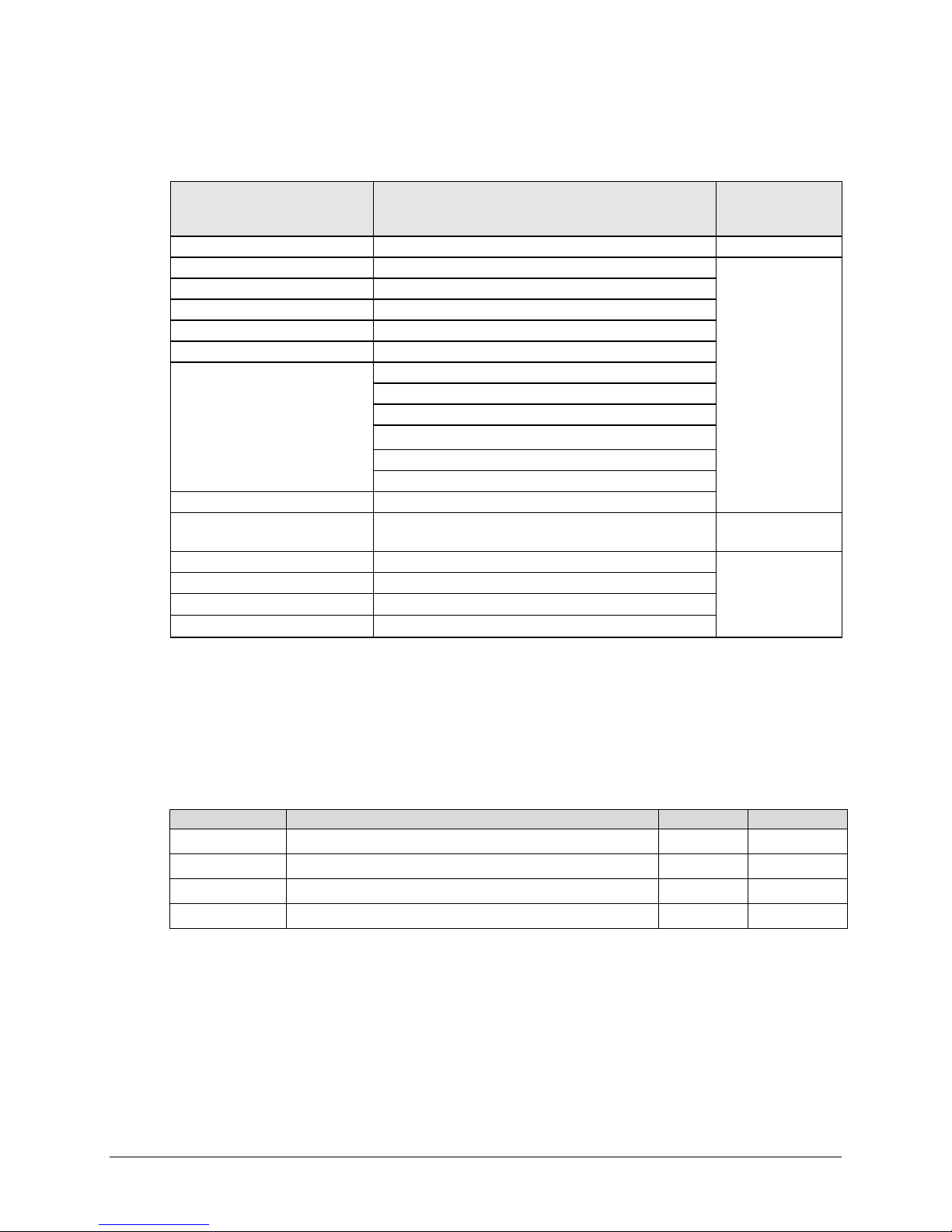
CDM-Qx/QxL Multi-Channel Satellite Modem with DoubleTalk™ Carrier-in-Carrier® Revision 7
Introduction MN/CDMQx.IOM
Table 1-2. FAST and FAST-accessible Hardware Options
Modulator & Demodulator
Options
Low Rate Variable Data rate 32 kbps to 5 Mbps Base Unit
Mid-Rate Variable Data rate 32 kbps to 10.0 Mbps
Full Rate Variable Data rate 32 kbps to 20.0 Mbps
8-PSK Modulation Type
16-QAM Modulation Type
D&I++ Drop and Insert
DoubleTalk Carrier-in-Carrier
Redundancy Capability 1:1 or 1:2 or 1:3 Redundancy
Turbo Codec – high rate
High Stability Reference Internal 10 MHz reference – 6 x 10⁻⁸
Low Stability Reference Internal 10 MHz reference – 1 x 10⁻⁶
75Ω TX/RX Impedance 75Ω impedance with BNC female connectors
50Ω TX/RX Impedance 50Ω impedance with N female connectors (L-Band)
Description and Comments
128 ksps – 512 kbps
128 ksps – 1 Mbps
128 ksps – 2.5 Mbps
128 ksps – 5 Mbps
128 ksps – 10 Mbps
128 ksps – 20 Mbps
20 Mbps Turbo Codec
512 kpbs, 2048 kbps, 5 Mbps, 10 Mbps, 20 Mbps
Option
Installation
Method
FAST
FAST or
Hardware
Hardware
(Factory-installed
only)
1.3.13 Supporting Hardware and Software
Redundancy Applications
For 1:1 and 1:N redundancy applications, the CDM-Qx/QxL is supported by the following Comtech
EF Data switching products:
CEFD Product Description CDM-Qx CDM-QxL
CRS-311 1:1 Redundancy Switch
CRS-300 1:10 Redundancy Switch
CRS-280*
CRS-280L*
* For use in 1:N applications only. Up to one modulator and one demodula tor allowed per CDM-Qx/QxL.
IF Switch (70/140 MHz)
IF Switch (L-Band)
ODU Interoperability via FSK / EDMAC
The CDM-QxL incorporates a Frequency Shift Keyed (FSK) serial l ink that, wh en activat ed on the
Rx-IF port of a CDM-QxL, enables the modem to communi cate with the Comtech EF Data line of
RF Ku- and C-Band Transceivers.
X X
X X
X
X
1–12

CDM-Qx/QxL Multi-Channel Satellite Modem with DoubleTalk™ Carrier-in-Carrier® Revision 7
Introduction MN/CDMQx.IOM
On the CDM-QxL, when activated on the Tx-IF port, this link can communicate with an FSKcapable Block Upconverter (BUC) or, conversely, when activ ated on the Rx-IF port, a Low-Noise
Block Downconverter (LNB).
In this manner, the user may monitor, co nfigure, and control the Transceiv er, BUC or LNB via the
modem’s front panel display and keypad, or by using the modem’s remote control interface.
The EDMAC overhead channel may also be used to convey M&C data to a RF Transceiver at the
distant end of a satellite link if it is connected to a CDM-Qx, or to a BUC or LN B at the d istant en d
of a satellite link if it is connected to a CDM-QxL.
For the CDM-QxL, this FSK interface with the BUC includes a BUC output power lev eling mode,
whereby the modem M&C monitors th e detec ted BUC output po wer level repo rted on the FSK link
and automatically adjusts the modem Tx output power to maintain a constant BUC Tx output level.
1.4 New in this Release
Revision 7 of this manual denotes a complete rewrite of the CDM-Qx S atellite Modem Instal lation
and Operation Manual (CEFD P/N MN/C DMQX.IO M). It is intend ed replace al l previous version s
of this document in their entirety. All content ha s been reorganized to conform to curr ent Comtech
EF Data Technical Publications Standards and Practices.
Note that firmware for the CDM-Qx/QxL is chassis-specific, as explained in Sect. 1.3.11. Users
are strongly urged to upgrade the CDM-Qx/QxL to the appropriate current firmware release – for
further information, refer to Chapter 4. FLASH UPGRADING.
1.4.1 CDM-Qx/QxL Firmware Release Notes
FW-0000107 Ver. 2.1.5 Release (5/20/09) / FW/11245 Ver. 1.6.6 Release (5/20/09)
New Features:
• None.
Feature Enhancements:
• Upgrade power ratio monitor reporting functionality.
1–13
CDM-Qx/QxL Multi-Channel Satellite Modem with DoubleTalk™ Carrier-in-Carrier® Revision 7
Introduction MN/CDMQx.IOM
1.5 Summary of Specifications
1.5.1 Modulator
Note: Features not in the initial product release are identified in parentheses.
Modulation
Symbol rate range
Data rate range
Operating modes
FEC
Transmit filtering
Scrambling
Output frequency
External Reference
Harmonics
and spurious
Transmit On/Off
Ratio
Output phase noise
Output power
Power accuracy
Output Connector
Output Return Loss
Clocking Options
External TX
Carrier Off
See Table A-5
Up to 10 Msps (lower end is modulation and FEC rate dependant). Refer to Figure A-1.
See Table A-5
Transparent, closed network, DoubleTalk™ Carrier-in-Carrier®
See Table A-5
Per INTELSAT IESS-308 (0.35) or 0.20 (for use with closer adjacent channel spacing)
V.35 or synchronous
50 to 90, 100 - 180 MHz, 100 Hz resolution (70/140 MHz IF)
950 to 1950 MHz, 100 Hz resolution (L-Band)
Stability ± 1 ppm, 0 to 50
Stability ± 0.06 ppm, 0 to 50oC (32 o to 122 oF) (Optional high-stability internal reference)
Stability ± 0.06 ppm, 0 to 50oC (32 o to 122 oF) (standard reference for L-Band)
1, 2, 5, 10, or 20 MHz @ 0 dBm to +20 dBm. Internal reference phase locks to external
reference.
Greater than -55 dBc/4 kHz (typically <-60 dBC/4kHz) – measured from 25 to 400 MHz
(70/140MHz IF)
Greater than -55 dBc/4 kHz (typically <-60 dBC/4kHz) – measured from 500 to 2500 MHz
(L-Band)
Spurious measured relative to an unmodulated (CW) carrier
55 dB minimum
0
rms double sided, 100 Hz to 1MHz
< 0.48
(minimum of 10 dB better overall than the INTELSAT IESS-308/309 requirement)
-5 to -25 dBm, 0.1 dB steps (70/140MHz IF)
-5 to -45 dBm, 0.1 dB steps (L-Band).
Refer to Automatic Uplink Power Control section.
±1.0 dB over frequency, temperature, and number of modulators installed in the chassis
Type BNC Female (70/140MHz IF)
Type N Female (L-Band)
≥ 19 dB (70/140MHz IF)
≥ 10 dB (L-Band)
Internal, ±1ppm or 0.06 ppm (SCT)
External, locking over a ±100 ppm range (TT)
Loop timing (Rx satellite clock) - supports asymmetric operation - Rx and Tx data rates do
not need to be identical
External Clock at transmit data rate.
By TTL 'low' signal or external contact closure - hardware function automatically over-rides
processor
o
C (32 o to 122 oF) (standard low-stability internal reference)
1–14
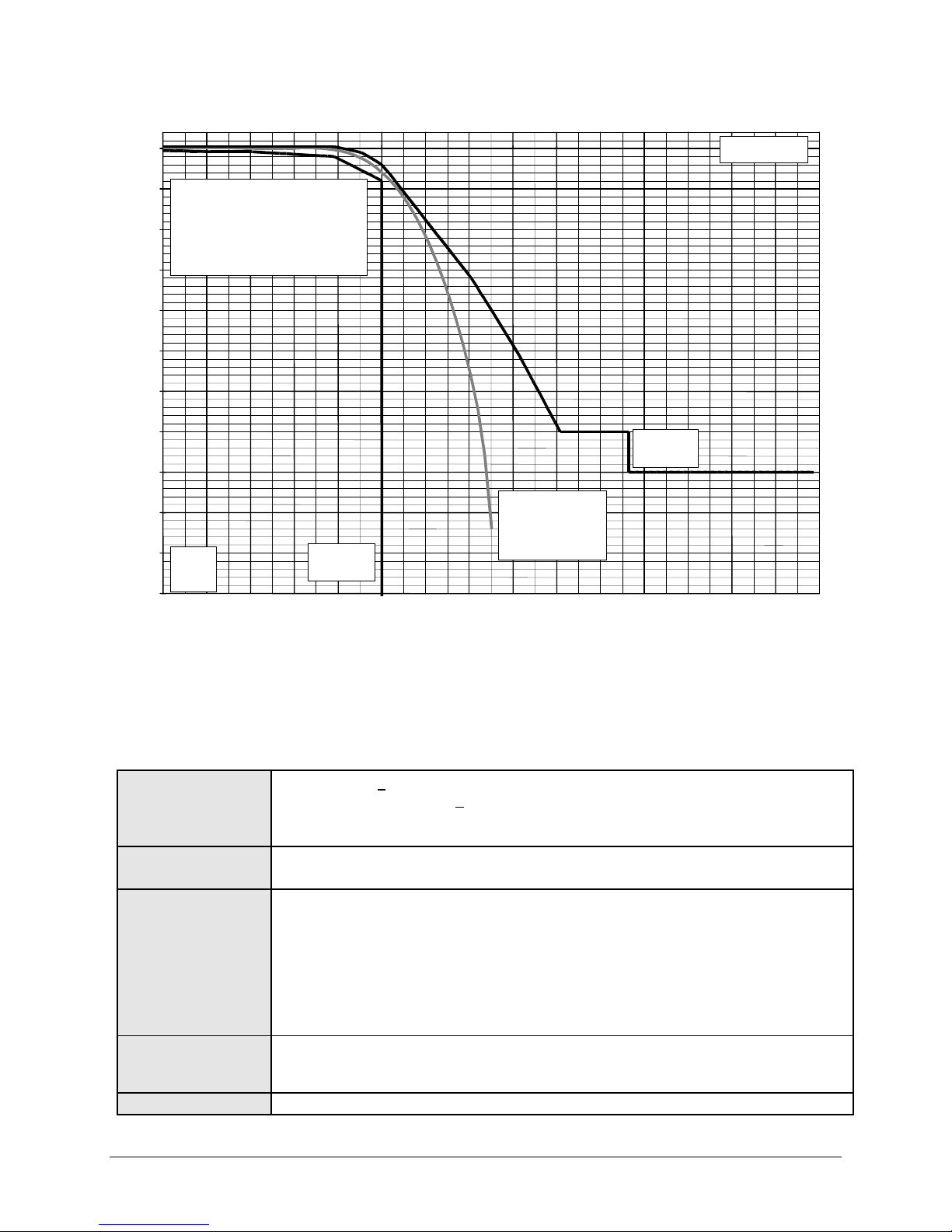
CDM-Qx/QxL Multi-Channel Satellite Modem with DoubleTalk™ Carrier-in-Carrier® Revision 7
Introduction MN/CDMQx.IOM
0.00 0.10 0.20 0.30 0.40 0.50 0.60 0.70 0.80 0.90 1.00 1.10 1.20 1.30 1.40 1.50
0
-5
-10
Comtech EF Data
CDM-Qx Transmit
Power Spectral Density,
referred to symbol rate
-15
-20
-25
-30
-35
-40
-45
-50
Spectral
density,
dB
-55
Intelsat
IESS 308/309
Limit
Symbol Rate, R
s
Intelsat
CDM-Qx Modulator
typically < -50 dB, and
guaranteed to be
< -45 dB at offsets
> 0.75 Rs
IESS 308/309
Limit
1.5.2 Demodulator
Note: FEC, Data rate range, operating modes, descrambling, input impedance/return loss etc, as
per Modulator.
Input power range
(70/140MHz IF)
Input power range
(L-Band)
Acquisition range
Acquisition time
Clock tracking range
-15 to -45 dBm, <
-15 to -40 dBm, > 2.048 and <
-15 to -35 dBm > 4.096 Msps (desired carrier)
+35 dBc maximum composite, up to -5 dBm
-130 + 10log(Symbol Rate in Hz) minimum signal level
50dB AGC range
±1 to ±32 kHz, Symbol rate > 64 ksps (70/140 MHz)
±1 to ± (Symbol rate/2) kHz , Symbol Rate <=64 ksps (70/140 MHz)
±1 to ±200 kHz, Symbol rate > 625 ksps (L-Band)
±1 to ± 32 kHz, 64 ksps < Symbol Rate <=625 ksps (L-Band)
±1 to ± (Symbol rate/2)kHz, Symbol Rate <=64ksps (L-Band)
Programmable in 1 kHz increments.
Highly dependent on data rate, FEC rate, and demodulator acquisition range.
Note that Reed-Solomon increases acquisition time, due to the additional time taken for the
RS decoder to declare synchronization.
± 100 ppm min
Figure 1-6. Power Spectral Density Chart
2.048 Msps (desired carrier)
4.096 Msps (desired carrier)
1–15

CDM-Qx/QxL Multi-Channel Satellite Modem with DoubleTalk™ Carrier-in-Carrier® Revision 7
V
V
Introduction MN/CDMQx.IOM
ITERBI BER
performance
(met in the presence
of two adjacent
carriers, each 7 dB
higher than the
desired carrier)
ITERBI and RS
220,200 or 200,180
Outer Code BER
(with two adjacent
carriers, each 7 dB
higher than the
desired carrier)
8-PSK/TCM CODEC
BER
(with two adjacent
carriers, each 7 dB
higher than the
desired carrier)
TURBO PRODUCT
CODEC
Rate 1/2 QPSK
Rate 21/44 BPSK
Rate 5/16 BPSK
BER
(with two adjacent
carriers, each 7 dB
higher than the
desired carrier)
For:
BER=10
BER=10
BER=10-7
For:
BER=10
BER=10-6
BER=10-7
For:
BER=10-5
BER=10
BER=10-8
For:
BER=10
BER=10
BER=10-8
Rate 1/2 (B, Q)
Guaranteed Eb/No:
(typical value in
parentheses)
-5
5.4 dB (4.9 dB)
-6
6.0 dB (5.5 dB)
6.7 dB (6.2 dB)
Rate 1/2 (B, Q)
Guaranteed Eb/No:
(typical value in
parentheses)
-5
4.3 dB (4.0 dB)
4.4 dB (4.1 dB)
4.5 dB (4.2 dB)
Rate 2/3 8-PSK/TCM
Guaranteed Eb/No:
(typical value in
parentheses)
7.9 dB (7.2 dB)
-7
9.5 dB (8.7 dB)
10.4 dB (9.5dB)
Rate 1/2 (Q)
Guaranteed Eb/No:
(typical value in
parentheses)
-6
-7
2.9 dB (2.6 dB)
3.1 dB (2.7 dB)
3.3 dB (2.8 dB)
Rate 3/4 (Q)
Guaranteed Eb/No:
(typical value in
parentheses)
6.8 dB (6.3 dB)
7.4 dB (6.9 dB)
8.2 dB (7.7 dB)
Rate 3/4 (Q)
Guaranteed Eb/No:
(typical value in
parentheses)
5.6 dB (4.7 dB)
5.8 dB (4.8 dB)
6.0 dB (5.2 dB)
Rate 2/3 8-PSK/TCM
w/concatenated RS
Guaranteed Eb/No:
(typical value in
parentheses)
6.3 dB (5.4 dB)
6.7 dB (5.8 dB)
6.9 dB (6.0 dB)
Rate 21/44 (B)
Guaranteed Eb/No:
(typical value in
parentheses)
2.8 dB (2.5dB)
3.1 dB (2.8 dB)
3.3 dB (2.90dB)
Rate 7/8 (Q)
Guaranteed Eb/No:
(typical value in
parentheses)
7.7 dB (7.2 dB)
8.4 dB (7.9 dB)
9.0 dB (8.6 dB)
Rate 7/8 (Q)
Guaranteed Eb/No:
(typical value in
parentheses)
6.5 dB (6.0 dB)
6.7 dB (6.2 dB)
6.9 dB (6.5 dB)
Rate 5/16 (B)
Guaranteed Eb/No:
(typical value in
parentheses)
2.4 dB (2.1dB)
2.6 dB (2.3dB)
2.7 dB (2.4dB)
TURBO PRODUCT
CODEC
Rate 3/4 QPSK
Rate 3/4 8-PSK
Rate 3/4 16-QAM
BER
(with two adjacent
carriers, each 7 dB
higher than the
desired carrier)
For:
BER=10
BER=10
BER=10
Rate 3/4 (Q)
Guaranteed Eb/No:
(typical value in
parentheses)
-6
-7
-8
3.8dB (3.4dB)
4.1dB (3.7dB)
4.4dB (4.0dB)
Rate 3/4 (8-PSK)
Guaranteed Eb/No:
(typical value in
parentheses)
6.2 dB (5.8 dB)
6.4 dB (6.0 dB)
6.8 dB (6.3 dB)
Rate 3/4 (16-QAM)
Guaranteed Eb/No:
(typical value in
parentheses)
7.4dB (7.0 dB)
7.8 dB (7.3 dB)
8.2 dB (7.7 dB)
1–16

CDM-Qx/QxL Multi-Channel Satellite Modem with DoubleTalk™ Carrier-in-Carrier® Revision 7
Introduction MN/CDMQx.IOM
TURBO PRODUCT
CODEC
Rate 7/8 QPSK
Rate 7/8 8-PSK
Rate 7/8 16-QAM
BER
(with two adjacent
carriers, each 7 dB
higher than the
desired carrier)
TURBO PRODUCT
CODEC
Rate 17/18 QPSK
Rate 17/18 8-PSK
BER
(with two adjacent
carriers, each 7 dB
higher than the
desired carrier)
HIGHER-ORDER
MODULATION AND
CODING
(with two adjacent
carriers, each 7 dB
higher than the
desired carrier)
Plesiochronous /
Doppler Buffer
Monitor Functions
For:
BER=10
BER=10
BER=10-8
For:
BER=10
BER=10-7
BER=10
For:
BER=10
BER=10-8
Rate 7/8 (Q)
Guaranteed Eb/No:
(typical value in
parentheses)
-6
-7
4.3 dB (4.0 dB)
4.4 dB (4.1 dB)
4.5 dB (4.2 dB)
Rate 17/18 (Q)
Guaranteed Eb/No:
(typical value in
parentheses)
-6
6.4 dB (6.0 dB)
6.7 dB (6.3 dB)
-8
6.9 dB (6.5 dB)
16-QAM Rate 3/4
Viterbi/RS
Guaranteed Eb/No:
(typical value in
parentheses)
-6
8.1 dB (7.5 dB)
8.6 dB (8.0 dB)
Rate 7/8 (8-PSK)
Guaranteed Eb/No:
(typical value in
parentheses)
7.3 dB (6.6 dB)
7.4 dB (6.7 dB)
7.5 dB (6.8 dB)
Rate 17/18 (8-PSK)
Guaranteed Eb/No:
(typical value in
parentheses)
9.3 dB (8.9 dB)
9.8 dB (9.4 dB)
10.3 dB (9.9 dB)
16-QAM Rate 7/8
Viterbi/RS
Guaranteed Eb/No:
(typical value in
parentheses)
9.5 dB (9.0 dB)
10.1 dB (9.5 dB)
Rate 7/8 (16-QAM)
Guaranteed Eb/No:
(typical value in
parentheses)
8.1 dB (7.7 dB)
8.2 dB (7.8 dB)
8.3 dB (7.9 dB)
Selectable size of 512, 1024, 2048, 4096, 8192, 16384 and a32768 bits
Size selection is displayed in bytes
Supports asymmetric operation - when buffer is clocked from Tx clock, Rx and Tx rates do
not need to be identical
Eb/No estimate, 2 to 16 dB (± 0.10 dB accuracy)
Corrected Bit Error Rate, 1E-3 to 1E-10
Frequency offset, ± 32 kHz range, 100 Hz resolution (70/140 MHz IF)
Frequency offset, ± 200 kHz range, 100 Hz resolution (L-Band)
Buffer fill state, in percent
Receive signal level accuracy = ± 3.0 dB)
1–17

CDM-Qx/QxL Multi-Channel Satellite Modem with DoubleTalk™ Carrier-in-Carrier® Revision 7
Introduction MN/CDMQx.IOM
1.5.3 Data Interfaces
Note: Features not in the initial product release are identified in parentheses.
EIA-530
EIA-530
(3 selectable modes)
G.703 (Balanced)
G.703 (Unbalanced)
Multi-Port G.703 (Bal)
1 to 4 Ports E1 w/ D&I
EIA-612 / 613
(HSSI)
Modem Alarms
(Present on all
modules)
Serial Remote Control
10/100BaseT
Synchronous RS-232
EIA-422/EIA-530 DCE (Rates up to 12 Mbp s)
Also supports X.21(Rates up to 2.048 Mbps)
V.35 DCE (Rates up to 12 Mbps)
Synchronous RS-232 (Rates up to 300 kbps)
1.544 Mbps T1 (Balanced 100 Ω)
2.048 Mbps E1 (Balanced 120 Ω)
1.544 Mbps T1 (unbalanced 75 Ω)
2.048 Mbps E1 (unbalanced 75 Ω)
8.448 Mbps E2 (unbalanced 75 Ω)
2.048 Mbps E1 (balanced 120 Ω)
Note: All 4 ports must be synchronous
EIA-612/EIA-613 (Rates up to 20 Mbps)
Relay outputs (Tx, Rx & unit faults)
Demodulator I & Q test outputs (constellation )
Demodulator Rx Signal Level output (0 to 2.5 vol ts)
External carrier off inpu t
EIA-232 or EIA-485 modem control and monitoring 9-pin D-sub (male)
IP based monitoring & control RJ-45
25-pin D-sub (female)
15-pin D-sub (female)
BNC (female)
(4) RJ-45 Ports
50-pin, mini-D SCSI-II
HSSI (female)
15-pin D-sub (male)
1.5.4 Automatic Uplink Power Control
Operating Mode
Target Eb/No range
Max AUPC range
Monitor functions
Requires Closed Network Framed mode for transport of Eb/No information from remote
modem (EDMAC can be enabled or disabled)
0 to 9.9 dB at remote demod (default is 4.0 dB)
0 to 9 dB (default is 3 dB)
Remote demod Eb/No
Tx power level increase
(front panel or via remote control interface)
1–18

CDM-Qx/QxL Multi-Channel Satellite Modem with DoubleTalk™ Carrier-in-Carrier® Revision 7
Introduction MN/CDMQx.IOM
1.5.5 Data Rate Ranges
FEC Type Modulation Code Rate Data Rate Range
Viterbi BPSK Rate 1/2 32 kbps to 5 Mbps
Viterbi QPSK Rate 1/2 32 kbps to 10 Mbps
Viterbi QPSK Rate 3/4 32 kbps to 15 Mbps
Viterbi QPSK Rate 7/8 32 kbps to 17.5 Mbps
Viterbi + R-S BPSK Rate 1/2 32 kbps to 4.5 Mbps
Viterbi + R-S QPSK Rate 1/2 32 kbps to 9.1 Mbps
Viterbi + R-S QPSK Rate 3/4 32 kbps to 13.7 Mbps
Viterbi + R-S QPSK Rate 7/8 32 kbps to 16 Mbps
Viterbi + R-S 16-QAM Rate 3/4 349.1 kbps to 20 Mbps
Viterbi + R-S 16-QAM Rate 7/8 407.3 kbps to 20 Mbps
TCM + RS 8-PSK Rate 2/3 232.7 kbps to 18.3 Mbps
TPC BPSK Rate 5/16 32 kbps to 3.1 Mbps
TPC BPSK Rate 21/44 32 kbps to 4.7 Mbps
TPC QPSK Rate 21/44 32 kbps to 9.5 Mbps
TPC QPSK Rate 3/4 32 kbps to 15 Mbps
TPC QPSK Rate 7/8 32 kbps to 17.5 Mbps
TPC QPSK Rate 17/18 32 kbps to 18.888 Mbps
TPC 8-PSK Rate 3/4 288 kbps to 20 Mbps
TPC 8-PSK Rate 7/8 336 kbps to 20 Mbps
TPC 8-PSK Rate 17/18 362 kbps to 20 Mbps
TPC 16-QAM Rate 3/4 384 kbps to 20 Mbps
TPC 16-QAM Rate 7/8 448 kbps to 20 Mbps
1.5.6 Framing Summary (Future)
Feature Transparent EDMAC (Future)
5% to 2 Mbps
Overhead added
Available data rates and format
Overhead components
Additional Reed-Solomon
Overhead
Scrambling (see Note 1 )
Notes:
1. When Reed-Solomon is Off.
2. % for Rates 5/16, 21/44 BPSK Turbo, Rate 21/44 QPSK Turbo, and all rates > 2 Mbps.
None
All rates and formats All rates and formats
None
220/200
225/205
219/201 for IESS-310 mode
Basic ITU
V.35 (Intelsat)
1.5%
(see Note 2)
Remote control link between
modems’ processor
200/180
Proprietary scrambler
1–19

CDM-Qx/QxL Multi-Channel Satellite Modem with DoubleTalk™ Carrier-in-Carrier® Revision 7
Introduction MN/CDMQx.IOM
1.5.7 Miscellaneous
Front panel
Loopbacks
Fault relays
M&C Interface
M&C Software
CDM-Qx
AC
Consumption
AC Operating Voltage
DC Operating Voltage
Temperature
Dimensions
Weight
(70/140 MHz)
CDM-QxL
(L-band)
Operating
Storage
1.5.8 Approvals
• Tactile keypad: 6 keys (Up/Down, Left/Right, Enter/Clear)
• VFD – Vacuum Fluorescent Display (blue): 2 lines of 40 characters each
Internal IF loopback, RF loopback, digital loopback, and inward/outward
loopback
Hardware fault, RX and TX Traffic Alarms
EIA-232 and EIA-485 (addressable multidrop, 2-wire or 4-wire), 10/100 BaseT
Ethernet
SATMAC software for control of local and distant units
120 watts (maximum)
250 watts (maximum)
100 to 240 VAC, +6%/-10% - autosensing
(total absolute max. range is 90 to 254 VAC)
36 to 72 VDC, 6.25 amps
o
0 to 50
-25 to 85
1.75” H x 19” W x 19” D
(44 mm H x 480 mm W x 480 mm D)
< 20 lbs (7.0 kg) approx (depends on configuration)
C (32 to 122oF)
o
C (-13 to 185oF)
CE Mark
FCC
EMC Safety
FCC Part 15 Class B
1–20

2.1 Unpacking
The CDM-Qx/QxL Satellite Modem and its Installation and Operation Manual are packaged and
shipped in a pre-formed, reusable cardboard carton containing foam spacing for maximum
shipping protection.
Do not use any cutting tool that extends more than 1” into the container and
CAUTION
IMPORTANT
Unpack and inspect the CDM-Qx/QxL as follows:
Step Procedure
cause damage to the unit.
Be sure to keep all shipping materials for the carrier's inspection.
Chapter 2. INSTALLATION
Inspect shipping containers for damage. If shipping containers are damaged, keep
1
2 Remove the packin g list from the outside of the shipping carton.
3
4
5
6
7 Refer to the following sections for further installation instructions.
them until the contents of the shipment have been carefully inspected and
checked for normal operation.
Open the carton by cutting the tape at the top of the carton (indicated by
THIS END
Remove the cardboard/foam space covering the modem. Remove the modem,
manual and power cord from the carton.
Check the contents against the packing list to verify completeness of the
shipment.
Inspect the equipment for any possible damage incurred during shipment. If
damage is evident, contact the carrier and Comtech EF Data immediately and
submit a damage report.
).
2–1
OPEN

CDM-Qx/QxL Multi-Channel Satellite Modem with DoubleTalk™ Carrier-in-Carrier® Revision 7
Installation MN/CDMQX.IOM
2.2 Mounting
If the CDM-Qx/QxL is to be mounted in a rack, ensure that there is adequate clearance for
ventilation, particularly at the sides. In rack systems where there is high heat dissipation, forced
air cooling must be provided by top or bottom mounted fans or blowers. Under no circumstance
should the highest internal rack temperature be allowed to exceed 50°C (122°F).
2.2.1 Method A: Optional Rear-Mounting Support Brackets
Install optional rear-mounting support brackets using mounting kit KT/6228-2:
Quantity Part Number Description
2 HW/10-32SHLDR Screw, #10 Shoulder
4 HW/10-32FLT Washer, #10 Flat
2 HW/10-32SPLIT Washer, #10 Split
2 HW/10-32HEXNUT Nut, #10 Hex
2 FP/6138-1 Bracket, Rear Support
4 HW/10-32x1/2RK Bolt, #10 Rack Bracket
The tools required for this installation are a medium Phillips™ screwdriver and a 5/32-inch
SAE Allen™ Wrench. The kit is installed as illustrated in Figure 2-1 via the following
procedure:
Step Procedure
Secure the #10 shoulder screws to the unit chassis through the rear right and left
1
2
3
side mounting slots, using the #10 flat washers, #10 split washers, and #10 hex
nuts as shown.
Install the rear support brackets onto the equipment rack threaded rear mounting
rails, using the #10 rack bracket bolts.
Mount the unit into the equipment rack, ensuring that the shoulders of the #10
shoulder screws properly engage into the rear support bracket slots.
2–2

CDM-Qx/QxL Multi-Channel Satellite Modem with DoubleTalk™ Carrier-in-Carrier® Revision 7
Installation MN/CDMQX.IOM
Support Bracket
#10 Bracket Bolt
#10 Shoulder Screw
#10 Flat Washer
#10 Flat Washer
#10 Split Washer
Equipment Rack
Rear Mounti ng Ra il
Figure 2-1. Installation of Optional Rear-Mounting Support Brackets
#10 Hex Nut
Back of unit
2–3

CDM-Qx/QxL Multi-Channel Satellite Modem with DoubleTalk™ Carrier-in-Carrier® Revision 7
Installation MN/CDMQX.IOM
2.2.2 Method B: Optional Bearingless Side-Railings
Figure 2-2 depicts installation of the optional side-railings FP/SL0006, using standard shop
tooling and customer-furnished standard shop hardware:
Optional Side-railings FP/SL0006
Quantity CEFD Part Number Description
2 FP/SL0006 Bearingless Side-Railing
Figure 2-2. Installation of Optional Side-Railings (FP/SL0006)
2.3 Configuration
The unit ships with a default Viterbi 192 kbps, QPSK, Rate 3/4 configuration. There are no
internal jumpers to configure, no interface cards to install, and no other options to install: all
configurations are carried out entirely in software.
The unit should first be configured locally, using the front panel keypad and display. Refer to
Chapter 5. FRONT PANEL OPERATION for details on how to fully configure the unit for the
desired operating parameters.
Note: The auto-sensing AC power supply does not require any adjustments. Simply plug in the
supplied line cord, and turn on the switch on the rear panel.
2–4

CDM-Qx/QxL Multi-Channel Satellite Modem with DoubleTalk™ Carrier-in-Carrier® Revision 7
Installation MN/CDMQX.IOM
2.4 Select Internal IF Loop
Correct operation of the unit may be verified rapidly, without the need for externally connected
equipment, provided that there is at least one modulator and one demodulator installed:
1. From the top-level menu, select CONFIG Æ GROUP Æ MODEM.
This will require a modulator, with TX Output ON or ENABLED,
installed in the rear panel of the chassis into the slot above its
IMPORTANT
paired demodulator.
2. From the top-level menu, select TEST Æ IF LOOP (refer to Chapter 5. FRONT
PANEL OPERATION for details).
The demod should synchronize, and the green Rx TRAFFIC LED should illuminate. If the unit
does not pass this test, call Comtech EF Data Customer Support for assistance.
2.5 Connect External Cables
Having verified correct operation in IF loop, enter the desired configuration and proceed to
connect all external cables to the connectors outlined in the next chapter (Chapter 3. REAR
PANEL CONNECTOR PINOUTS). Should difficulties occur, call Comtech EF Data Customer
Support for assistance.
Observe the following:
• If modulators and demodulators are to be used without grouping them as a modem, a data
interface cable is required to plug into each unit. If a modulator and demodulator are
paired as a modem, the modulator must be located above the demodulator and a single
data interface cable is used simply by connecting it to the demodulator.
• If a modulator, demodulator, or pair (modem) is defined as a backup unit, a data interface
cable is not required to the unit or units.
Each modulator has an output power level in the range -5 to -25 dBm (-5 to -45
dBm for L-Band). Even though there is a single IF output connector and a single
CAUTION
IF input connector, all four slots are hooked up by way of internal power splitters
and summers. If two modulators are turned on, the total power out will be 3 dB
higher (assuming both modulators are set to the same power level). If four
modulators are turned on, the total power out will be 6 dB higher (assuming all
modulators are set to the same power level).
2–5

CDM-Qx/QxL Multi-Channel Satellite Modem with DoubleTalk™ Carrier-in-Carrier® Revision 7
Installation MN/CDMQX.IOM
Notes:
2–6
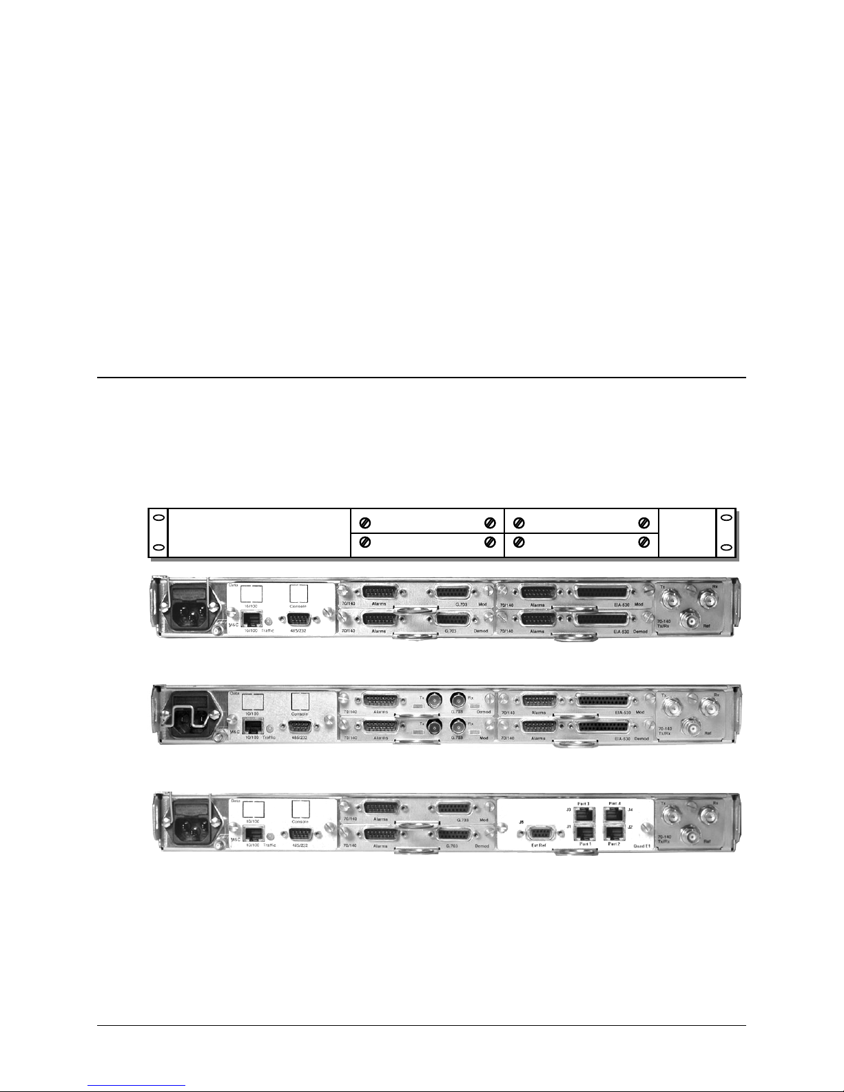
Chapter 3. REAR PANEL
3.1 Connector Overview
The CDM-Qx/QxL Multi-Channel Satellite Modem rear panel can be customized to meet user
requirements. As per the three configuration examples shown here in Figure 3-1, op
interface modules, used in tandem with the base chassis connectors, provide all necessary
external connections between the modem and other equipment.
Configuration #1 Modem 1 with G.703 T1/E1 Balanced (DB-15)
Configuration #2 Modem 1 with G.703 T1/E1 Unbalanced (BNC)
Configuration #3 Modem 1 with G.703 T1/E1 Balanced (DB-15) and
Modem 2 with EIA-422 (DB-25)
Modem 2 with EIA-422 (DB-25)
Quad E1 Interface Module, 1-4 Ports of E1, with D&I (4) RJ-45
Slot 1
Slot 2
CONNECTORS
tional data
Slot 3
Slot 4
IF I/OPrime Power & Control
Figure 3-1. CDM-Qx/QxL Rear Panel Configuration Examples
3–1

CDM-Qx/QxL Multi-Channel Satellite Modem with DoubleTalk™ Carrier-in-Carrier® Revision 7
Rear Panel Connectors MN/CDMQX.IOM
On the next page, Table 3-1 summarizes the connectors provided on the rear panel for both the
base chassis and the optional data interfaces, grouped according to service function.
Note the following:
1. One interface per Modem (i.e. Modulator and Demodulator card combination) or one
interface per Modulator card and Demodulator card are required if used independently.
2. When grouping a modulator and demodulator together to use as a modem, the modulator
must be located above the demodulator.
3. For redundant operation the backup unit does not need an interface.
4. For redundant operation the backup unit needs to be located in the lower right hand slot
(Slot #4) for single module redundancy. For modem redundancy the backup units must be
located in the right hand slots (Slots #3 & #4).
5. For the example shown for Configuration #1, because all modules have interfaces, the
following configurations are possible:
a. Two independent modulators - one with a G.703 balanced and the other with an EIA-
530 interface, with two independent demodulators one with a G.703 balanced and the
other with an EIA-530 interface.
b. Two independent modems - one with a G.703 balanced and the other with an EIA-
530 interface (located on the demodulators).
c. A 1:1 redundant modem, with the online unit configured with a G.703 interface. The
off line modules will provide the backup even with a different interface.
6. For the example shown for Configuration #3, the Quad E1 Interface Module is used in
Slots #3 and #4. The modulator in Slot 1 is grouped with the demodulator in Slot 2. This
unique combination allows the user to select the Quad E1 interface or the data interface
located in the modulator or demodulator.
3–2

CDM-Qx/QxL Multi-Channel Satellite Modem with DoubleTalk™ Carrier-in-Carrier® Revision 7
Rear Panel Connectors MN/CDMQX.IOM
Table 3-1. Rear Panel External Connections
Ref
Conn Type Function
Des
RF Output 75Ω or 50Ω
BNC
Type ‘N’
Type ‘N’
BNC External Reference for Modem Synthesizers
RF Input 75Ω or 50Ω
RF Output 50Ω
RF Input 50Ω
Unbalanced G.703 Data Output (incorrect slot
for IO)
Unbalanced G.703 Data Output (incorrect slot
for IO)
Name
Base Chassis: TYPICAL ALL CONFIGURATIONS (See Sect. 3.2)
AC Plug IEC Modem Power
DC Plug (Optional – CDM-QxL) Terminal Block Modem Power
Ground #10-32 Stud Grounding
M&C 10/100BaseT RJ-45 Remote Interface
485/232 9-Pin Male Remote Interface
70/140 Tx /Rx
(CDM-Qx)
L-Band Tx/Rx
(CDM-QxL)
Ref
Configuration #1: Modem1 with G.703 T1/E1 Balanced (DB-15); Modem2 with EIA-422 (DB-25)
Slot #1
Mod
Slot #2 Demod
Slot #3
Mod
Slot #4 Demod
Configuration #2: Modem 1 with G.703 EIA-422(DB-25); Modem2 with G.703 T1/E1 Unbalanced (BNC)
Slot #1
Mod
Slot #2 Demod
Slot #3 Mod
Slot #4
Demod
Configuration #3: Modem 1 with G.703 T1/E1 Balanced (DB-15) and Quad E1 Interface (1-4 Ports E1,w/ D&I)
Slot #1
Mod
Slot #2 Demod
Slot #3 and
Slot#4 Quad
E1
Note: The European EMC Directive (EN55022, EN50082-1) requires using properly shielded ca bles for DATA I/O.
Tx BNC
Rx
Tx
Rx
Alarms 15-Pin Male Form-C Alarms
G.703 15-Pin Female Balanced G.703 Data Input
Alarms 15-Pin Male Form-C Alarms
G.703 15-Pin Female Balanced G.703 Data Output, or Input/Output
Alarms 15-Pin Male Form-C Alarms
EIA-530 25-Pin Female Data Input
Alarms 15-Pin Male Form-C Alarms
EIA-530 25-Pin Female Data Output, or Input/Output
Alarms 15-Pin Male Form-C Alarms
G.703 BNC
Alarms 15-Pin Male Form-C Alarms
G.703 BNC Unbalanced G.703 Data input
Alarms 15-Pin Male Form-C Alarms
EIA-530 25-Pin Female Data Input
Alarms 15-Pin Male Form-C Alarms
EIA-530 25-Pin Female Data Output, or Input/Output
Alarms 15-Pin Male Form-C Alarms
G.703 BNC
Alarms 15-Pin Male Form-C Alarms
G.703 BNC Unbalanced G.703 Data input
Port 1 J1 RJ-45 Balanced E1 (Full E1 or Fractional D&I)
Port 2 J2 RJ-45 Balanced E1 (Full E1 or Fractional D&I)
Port 3 J3 RJ-45 Balanced E1 (Full E1 or Fractional D&I)
Port 4 J4 RJ-45 Balanced E1 (Full E1 or Fractional D&I)
Ext Ref J5 9-Pin Female Balanced E1 clock input and output
3–3

CDM-Qx/QxL Multi-Channel Satellite Modem with DoubleTalk™ Carrier-in-Carrier® Revision 7
Rear Panel Connectors MN/CDMQX.IOM
3.2 Base Chassis Connections
3.2.1 Power Connector
For continued operator safety, always replace the fuses with the correct type
IMPORTANT
and rating.
3.2.1.1 AC Power Connector
A standard, detachable, non-locking, 3-prong power cord (IEC plug) supplies
the Alternating Current (AC) power to the modem . Observe the follow ing:
Input Power 290W maximum, 110W typical without BUC power supply.
Input Voltage 100 - 240 volts AC, +6/-10% - autosensing
Connector Type IEC
Fuse Protection
AC Power Specifications
(total absolute max. range is 90 to 254 VAC)
CDM-Qx (70/140): 2.0A Slow-blow
Line and neutral fusing
20 mm type fuses
CDM-QxL (L-Band): 3.15A Slow-blow
Line and neutral fusing
20 mm type fuses
3.2.1.2 DC Power Supply (CDM-QxL, Optional)
A standard, 3-screw terminal block supplies the Direct Current (DC) power to
the modem. Observe the following:
Input Power 250W maximum, 110W typical without BUC power supply.
Input Voltage 36 to 72 VDC; 6.25 amps
Connector Type Terminal Block
Fuse Protection 6.25A Slow-blow
DC Power Specifications
With 24 VDC BUC: TBD
With 48 VDC BUC: TBD
3.2.2 Ground Connector
A #10-32 stud, located adjacent to the power connection on the rear panel of the
modem, is used for connecting a common chassis ground among equipment.
Note: The AC power connector provides the safety ground.
3–4
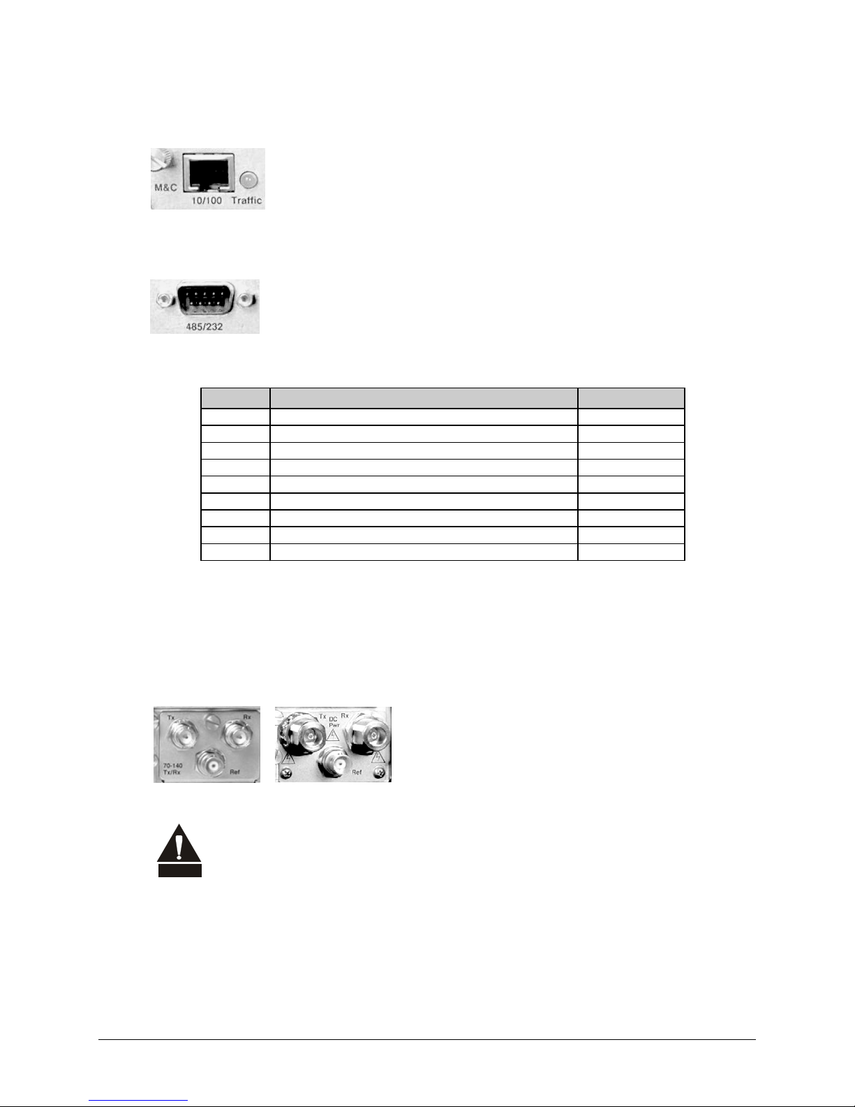
CDM-Qx/QxL Multi-Channel Satellite Modem with DoubleTalk™ Carrier-in-Carrier® Revision 7
Rear Panel Connectors MN/CDMQX.IOM
3.2.3 M&C 10/100BaseT Connector
The M&C 10/100BaseT connector is an 8-pin RJ-45 10/100BaseT Ethernet
port providing access to the modem’s management functions. A green LED
lights to acknowledge data traffic.
3.2.4 485/232 Connector
The 485/232 connector is a 9-pin 'D' type male (DB-9M). Access is provide d to
remote control ports of the modem , using both EIA-232 an d EIA-48 5.
Table 3-2. 485/232 (Remote Control) Connector Pin Assignments
Pin # Description Direction
1 Ground
2 RS-232 TX Data Out
3 RS-232 RX Data In
4 Reserved - do not connect to this pin
5 Ground
6 RS-485 RX Data B * In
7 RS-485 RX Data A * In
8 RS-485 TX Data B Out
9 RS-485 TX Data A Out
*Use for 2-wire RS-485 operation
3.2.5 Tx and Rx IF Connectors
The type of IF connectors available depends on the configuration ordered. The following reflects
the configurations available:
CA UTIO N
There may be DC voltages present on the Type ‘N’ Rx and Tx IF connectors, up
to a maximum of 48 volts.
-
3.2.6 Ext Ref Connector
The Ref connector is a Type ‘BNC’ female 50Ω connector, standard on all configurations as shown
in Sect. 3.2.5 (above). It provides an external reference input for the Tx and Rx IF synthesizers and
for the internal transmit clock. Th e load impedance is 60.4Ω, so the VSWR is less than 1.25:1 at
Tx and Rx:
• CDM-Qx (70/140 MHz) – BNC 75Ω
• CDM-QxL (L-Band) – Type ‘N’ 50Ω
3–5
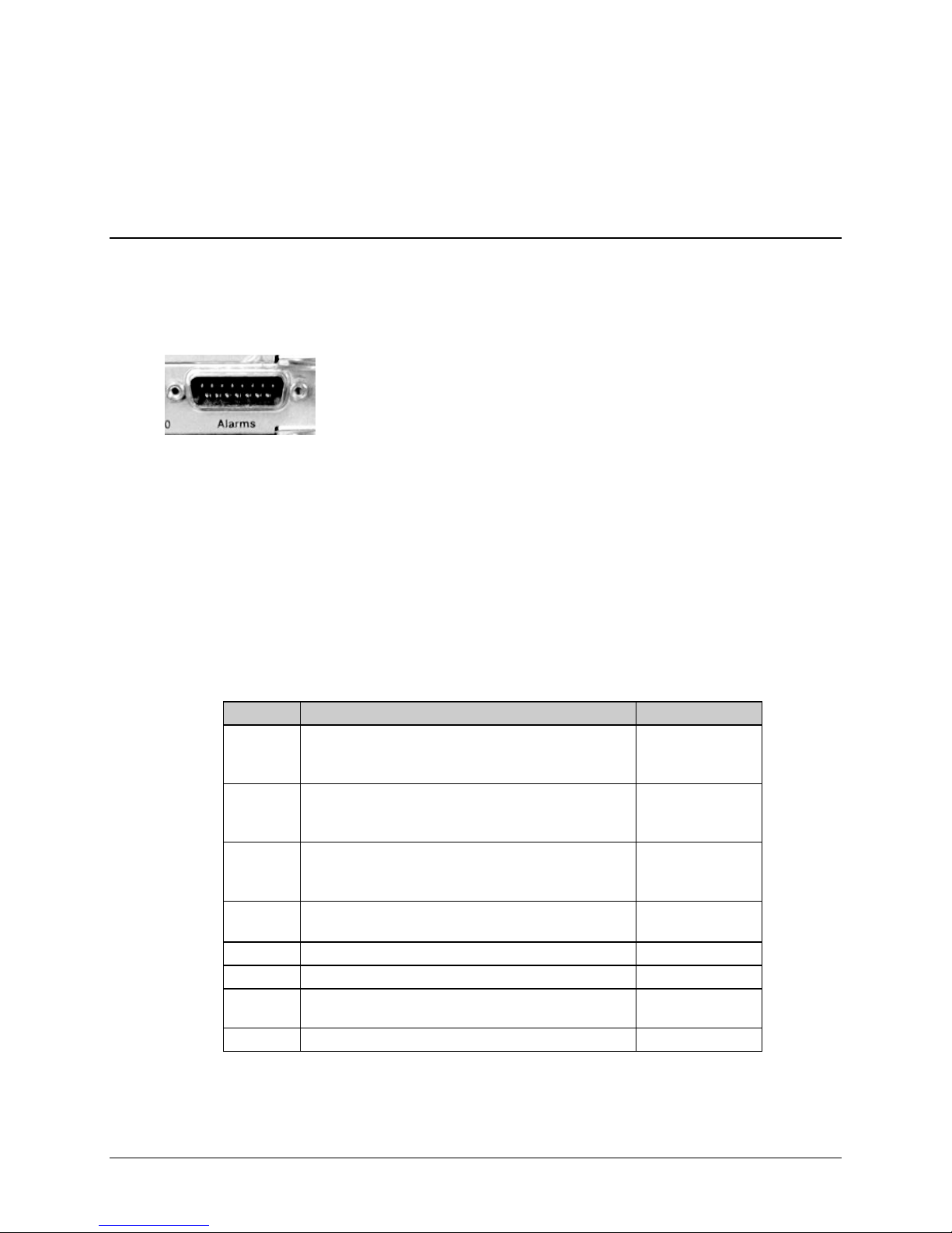
CDM-Qx/QxL Multi-Channel Satellite Modem with DoubleTalk™ Carrier-in-Carrier® Revision 7
Rear Panel Connectors MN/CDMQX.IOM
either 50Ω or 75Ω. Input level is 0 dBm minimum to +20 dBm maximum at either 1, 2, 5, 10, or 20
MHz. When external reference is en abled, the internal 10 MHz reference osci llator is phase lo cked
to the external reference input by a 10Hz bandwidth PLL. If no activity is present at the external
reference input, the modem will revert to the internal 10 MHz reference.
3.3 Data Interface Connectors
3.3.1 T ypical Alarms Connector
All available data interface modules contain a 15-pin 'D' type male
(DB-15M) Alarms connector. The Alarms connector provides the user
with access to the Form-C relay contacts, which indicate the fault status of
the unit. These are typically connected to an external fault monitoring
system, often found in satellite earth stations.
For a Modulator: TX fault and Unit Fault are supported. The transmit I and Q modulator
samples are available on this connector. Connecting these signals to an oscilloscope in X,Y mode
will provide the modulator signal constellation diagram, which is a useful diagnostic aid. A pin
also is provided which can mute the transmit carrier. This requires that the pin be shorted to
ground, or a TTL ‘low’.
For a Demodulator: RX fault and Unit Fault are supported. If a Modulator and Demodulator are
vertically grouped together as a modem, TX fault and the EXT Carrier OFF pin will also be
supported. The receive I and Q demodulator samples are provided on this connector. Connecting
these signals to an oscilloscope in X,Y mode will provide the receive signal constellation
diagram, which is a useful diagnostic aid.
Table 3-3. Alarms Interface Connector Pin Assignments
Pin # Signal Function Name
8
15
7
14
6
13
5
12
4
11
3
10 No Connection N/C
2 No Connection N/C
9
1 Ground GND
RX Traffic (De-energized, Faulted)
RX Traffic (Energized, No Fault)
RX Traffic
TX Traffic (De-energized, Faulted)
TX Traffic (Energized, No Fault)
TX Traffic
Unit Fault (De-energized, Faulted)
Unit Fault (Energized, No Fault)
Unit Fault
I Channel (Constellation monitor)
Q Channel (Constellation monitor)
EXT Carrier OFF (modulator or modulator and
demodulator grouped together)
RX-NC
RX-NO
RX-COM
TX-NC
TX-NO
TX-COM
UNIT-NC
UNIT-NO
UNIT-COM
TX or RX-I
TX or RX-Q
EXT-OFF
3–6

CDM-Qx/QxL Multi-Channel Satellite Modem with DoubleTalk™ Carrier-in-Carrier® Revision 7
Rear Panel Connectors MN/CDMQX.IOM
3.3.2 Balanced G.703 Connector Tx/Rx Connector
The Balanced G.703 connection is a 15-pin ‘D’ type female (DB-15F)
connector located on the rear mounting plate of the modulator or
demodulator. If a Modulator and Demodulator are vertically grouped together
as a modem, the data interface connector on the Demodulator switches to
duplex. This feature allows a single data interface connection to be used for a modem instead of
needing a “Y” cable. Otherwise, each module is a simplex data interface.
Table 3-4. Balanced G.703 Interface Connector Pin Assignments
Pin # Signal Function Name Direction
1 Drop Data Input ( - ) DDI– In
9 Drop Data Input (+) DDI+ In
2 Ground GND
10 Not Used
3 Insert Data Output ( - ) IDO– Out
11 Insert Data Output (+) IDO+ Out
4 Ground GND
12 Drop Data Output ( - ) DDO– Out (D&I Only)
5 Drop Data Output (+) DDO+ Out (D&I Only)
13 Insert Data Input ( - ) IDI– In (D&I Only)
6 Insert Data Input (+) IDI+ In (D&I Only)
14 Not Used
7 Not Used
15 Not Used
8 Not Used
3.3.3 Unbalanced G.703 Tx/Rx Connectors
Two female BNC 75Ω connectors are available for unbalanced operation at the
G.703 data rates of T1 (1.544 Mbps), E1 (2.048 Mbps), and E2 (8.448 Mbps).
If a Modulator and Demodulator are vertically grouped together as a modem,
the Tx data input interface connector on the Demodulator becomes active,
allowing duplex operation. Otherwise, the Tx data input connector is used on the modulator and
the Rx data output connector is used on the demodulator.
3–7

CDM-Qx/QxL Multi-Channel Satellite Modem with DoubleTalk™ Carrier-in-Carrier® Revision 7
Rear Panel Connectors MN/CDMQX.IOM
3.3.4 EIA-530 Data Interface Connector
The Data connector is a 25-pin ‘D’ type female (DB-25F). This connector
conforms to the RS-530 pinout, which allows for connection of different
electrical standards, including EIA-422, V.35, and EIA-232.
All data interfaces are duplex! They will only operate as duplex if a Modulator
and Demodulator are vertically grouped together as a modem. In that case the
data interface connector on the Demodulator switches to duplex. This feature
IMPORTANT
allows a single data interface connection to be used for a modem instead of
needing a “Y” cable. Otherwise, the data interface for each module will only
operate as simplex.
It is the responsibility of the user to provide the appropriate cables to connect
to this EIA-530 connector.
Table 3-5. RS-530 Data Interface Connector Pin Assignments
Pin #
2 TX Data A DTE to Modem SD A SD A BA 103
14 TX Data B DTE to Modem SD B SD B - 103
24 TX Clock A DTE to Modem TT A SCTE A DA 113
11 TX Clock B DTE to Modem TT B SCTE B - 113
15 INT TX Clock A Modem to DTE ST A SCT A DB 114
12 INT TX Clock B Modem to DTE ST B SCT B - 114
3 RX Data A Modem to DTE RD A RD A BB 104
16 RX Data B Modem to DTE RD B RD B - 104
17 RX Clock A Modem to DTE RT A SCR A DD 115
9 RX Clock B Modem to DTE RT B SCR B - 115
8 Receiver Ready A Modem to DTE RR A RLSD * CF 109
10 Receiver Ready B Modem to DTE RR B - - 109
23
7 Signal Ground - SG SG AB 102
1 Shield - Shield FG AN 101
Generic Signal
Description
External Carrier Off
(RS-232 ‘1' or TTL ‘low’ )
Direction
DTE to Modem - - - -
RS-422
RS- 530
LVDS
V.35 RS-232 Circuit #
Notes:
1. Receiver Ready is an RS-232 -level control signal on a V.35 interface.
2. DO NOT connect signals to pins which are not shown - these pins are reserved for use by the redundancy system.
3. ‘B’ signal lines are not used for RS-232 applications.
4. For X.21 operation, use the EIA-422 pins, but ignore RX Clock if the Modem is DTE, and ignore TX clocks if the
Modem is DCE.
3–8

CDM-Qx/QxL Multi-Channel Satellite Modem with DoubleTalk™ Carrier-in-Carrier® Revision 7
Rear Panel Connectors MN/CDMQX.IOM
3.3.5 Quad E1 Data Interface Connectors
The Quad E1 Data interface card allows the user to connect
one to four different terrestrial E1 ports, with each port
independently configurable for full E1 (framed or unframed E1
data), or fractional E1 (with D&I). These four RJ-45 ports –
labeled J1 Port 1 through J4 Port 4, respectively, on the
interface card – must be synchronized to each other.
Table 3-6. Quad E1 Data Interface J1-J4 Connector Pin Assignments
Pin # Signal Functi on Name Direction
1 DDI (+) Port_Tx+ In
2 DDI (-) Port_Tx– In
3 Ground Gnd --
4 IDO (+) Port_Rx+ Out
5 IDO (-) Port_Rx– Out
6 Ground Gnd --
7 Unused NC --
8 Unused NC --
The J5 Ext Ref connector is a 9-pin Type ‘D’ female (DB-9F) connector on the interface card that
provides two functions:
1. The first function is to provide an output E1 clock for the user to use as an E1 clock
reference (if needed for the terrestrial E1 equipment).
2. The second purpose of the connector is to allow the user to provide a reference E1 input
clock. The user can then use this E1 clock input to drive the demodulator receive buffer.
Refer to Chapter 5. FRONT PANEL OPERATION, in particular the section outlining
Config Æ Rx Æ Buf Æ RX BUFFER CLOCK SOURCE, for further information.
Table 3-7. Quad E1 Clock Interface J5, DB-9F Connector Pin Assignments
Pin # Signal Functi on Name Direction
1 E1 Clk Ref Out (-) E1 Clk Out (-) Out
2 Unused NC --
3 Ground Gnd --
4 Unused NC --
5 E1 Clk Ref In (+) E1 Clk In (+) In
6 E1 Clk Ref Out (+) E1 Clk Out (+) Out
7 Unused NC --
8 Unused NC --
9 E1 Clk Ref In (-) E1 Clk In (-) In
3–9

CDM-Qx/QxL Multi-Channel Satellite Modem with DoubleTalk™ Carrier-in-Carrier® Revision 7
Rear Panel Connectors MN/CDMQX.IOM
3.3.6 HSSI Interface and Connectors
This data interface is a plug-in module that inserts into the rear of the CDM-Qx/QxL’s Modulators
or Demodulators. It provides physical and electrical connection between the external terrestrial
device and the internal circuitry of the modulator or demodulator. By convention, a modem is Data
Communications Equipment (DCE) where Tx data enters the data interface and Rx data exits it.
The plug-in interface has full duplex capability.
The HSSI Card Data Interface Module plugs into the rear of the Modulator or Demodulator.
Figure 3-2 s
The HSSI interface provides:
• A single HSSI interface;
• A DCE Connection:
Additionally, the module is automatically configured for simplex-transmit or simplex-receive
operation when the module is plugged into a Modulator and Demodulator. When the
CDM-Qx/QxL is configured as a modem, only the Demodulator is required to have a HSSI
Interface and the Modulator is assigned a blank panel with the Alarms output only, as shown in
Figure 3-3 o
hows a block diagram of the interface.
o ST clock is sourced to the terrestrial interface for use as reference by DTE
o TT is treated as an incoming External Clock, and the interface phase locks to it
o TA / CA is supported
n the next page.
TT
SD
ST
TA
Common
J1
50 Pin HSSI Female
CA
RT
RD
Tx Clock Input (External)
Tx Data
Output Clock (Rate Programmable)
(RTS)
(CTS)
Rx Clock
Rx Data
Processor
Processor
Mux /
Mux /
Demux
Demux
PLL
PLL
Rx
Rx
Buffer
Buffer
Interface
Interface
Loopback
Loopback
Control
Control
HSSI Interface
Clk
&
Data
μC
Modem
Interface
Figure 3-2. HSSI Interface Block Diagram
A summary of specifications for th e interface is provided in Sect. 3.3.6.1; the HSSI connector pin
assignments are provided in Sect. 3.3.6.2 (see Sect. 3.3.1 for more information on the Alarms
connector).
3–10

CDM-Qx/QxL Multi-Channel Satellite Modem with DoubleTalk™ Carrier-in-Carrier® Revision 7
Ω
Rear Panel Connectors MN/CDMQX.IOM
3.3.6.1 HSSI Interface Specifications
Item Requirement
Data Rate Range
Signals Supported
Connector
Electrical
Electrical Typical
Minimum Buffer Size
Impedance
Signal Characteristics
Clock / Data
Relationship
Tx Clock Modes
Rx Clock Modes
Tx / Rx Clock
TA / CA
Operation
Signal Sense
Cable Length to 20
Mbps
Tx
Rx
Default
Selection
32 to 20 Mbps
ST, TT (or external) , SD, TA, CA, RT, RD, SG
DCE, 50-pin mini-D female per EIA-613 (HSSI)
Per EIA-612 (10KH ECL compatible).
Differential output voltage: >
Differential Input voltage: 150 to 1000 mV pp with 110 load
5.0 mS smallest buffer setting, 0.1 mS step size, 32 mS maximum size
110Ω for TT, SD, TA
ST, CA, RT, RD will drive 110
The A terminal is negative with respect to the B terminal for a binary 0 (Space or OFF)
state.
The A terminal is positive with respect to the B Terminal for a binary 1 (Mark or ON)
state.
The data transitions occur during the OFF to ON transition of the clock. Data is stable
during the ON to Off transition of the clock.
TT (Input clock) continuous.
ST (output clock) is continuous output, programmable in 1 bps steps or phase locked
to satellite clock
RT (output clock) is continuous from satellite, ST (internal clock), continuous from TT
Asymmetrical clocking with Rx Doppler buffer disabled
CA looped to TA
CA is asserted when there is no modem fault
Simplex (Tx only or Rx only) or full duplex
Programmable Normal or Inverted or TT and TD, RT and RD
2 M (6 ft) nominal, up to 15 M (49 ft) maximum – note higher data rates usually
require shorter cable lengths
590 mV pp into 110 load
and meet HSSI voltage levels
Figure 3-3. HSSI Interface Example
3–11

CDM-Qx/QxL Multi-Channel Satellite Modem with DoubleTalk™ Carrier-in-Carrier® Revision 7
Rear Panel Connectors MN/CDMQX.IOM
3.3.6.2 HSSI Connector Pin Assi gnments
The HSSI interface features a 50-pin female SCSI-2 connector
(mini-D), with pin assignments as follows:
Signal Function
Signal Ground SG 102 1, 26 Ground
Receive Timing RT 115 2, 27 from DCE
DCE Available CA 107 3, 28 from DCE
Receive Data RD 104 4, 29 from DCE
Loopback circuit C LC undefined 5, 30 from DCE Not used
Send Timing ST 114 6, 31 from DCE
Signal Ground SG 102 7, 32 Ground
DTE Available TA 108/2 8, 33 to DCE
Terminal Timing TT 113 9, 34 to DCE
Loopback Circuit A LA 143 10, 35 to DCE Not used
Send Data SD 103 11, 36 to DCE
Loopback Circuit B LB 144 12, 37 to DCE Not used
Signal Ground SG 102 13, 38 Ground
Not used undefined 14, 39 Not used
TX DVALID undefined 15, 40 Not used
Ext Carrier Off 16 to DCE Not used
reserved (to DCE) 17, 42 Not used
reserved (to DCE) 18, 43 Not used
Signal Ground SG 102 19, 44 Ground
Carrier Detect undefined 20 from DCE
undefined 45 Not used
undefined 21 Not used
reserved (to DTE) 46 Not used
undefined 22, 47 from DCE Not used
undefined 23, 48 from DCE Not used
142 24, 49 from DCE Not used
Signal Ground SG 102 25, 50 Ground
HSSI
Signal
EIA-613
Circuit
Pin # (+,-)
Circuit
Direction
Comment
3–12

Chapter 4. FLASH UPGRADING
4.1 Flash Updating via Internet
The CDM-Qx/QxL Open Network Satellite Modem eliminates the need for updating firmware by
physically replacing EPROMs. Instead, the CDM-Qx/QxL uses ‘Flash memory’ technology
internally. This makes software upgrading very simple, and updates can now be sent via the
Internet (Figure 4-1), via
This chapter outlines the complete upgrading process as follows:
• New firmware can be downloaded via the Internet to an external PC.
• The upgrade can be performed without opening the CDM-Qx/QxL by simply connecting the
unit to the USB or serial port of a computer.
• The firmware update is transferred, via File Transfer Protocol (FTP), to the CDM-Qx/QxL.
E-mail, or on CD.
Figure 4-1. Flash Update via Internet
4–1

CDM-Qx/QxL Multi-Channel Satellite Modem with DoubleTalk™ Carrier-in-Carrier® Revision 7
Flash Upgrading MN/CDMQX.IOM
4.2 Ethernet FTP Upload Procedure
1. Identify the reflashable product, firmware number, and version for download.
The current base modem M&C version can be viewed at the top level menu of the front panel
display (press the CLEAR key several times to view). The firmware information can also be
found within the SELECT: UTILÆ Firmware Æ Info Æ Image#1 or Image#2 menu trees.
Using serial remote control, the firmware revision levels can be queried with the following
commands:
Abbreviated: <0/SWR? or: Detailed: <0/FRW?
See Appendi x C. REMOTE CONTROL for more information on using remote commands
and queries.
Alternately, when using the Base Modem Web Server Interface, the Bootrom, Bulk1 and
Bulk2 firmware loads may be viewed after selecting the Unit Info hyperlink (available under
the Maint [Maintenance] page tab). For more information, refer to Chapter 7. WEB
SERVER INTERFACE.
2. Create a temporary directory (folder) on an external PC.
Windows: Select File > New > Folder, then rename the New Folder to "temp" or another
convenient, unused name. Assuming "temp" works, a "c:\temp" folder should now be created.
Note: The c: is the drive letter used in this example. Any valid writable drive letter can be
used.
CMD Prompt: At the command prompt (c:\>), type "mkdir temp” or “MD temp" without
quotes (mkdir and MD stand for make directory). This is the same as creating a new folder
from Windows. There should now be a "c:\temp" subdirectory created (where c: is the drive
letter used in the example).
3. Download the correct firmware file to this temporary folder.
As shown in Figure 4-1:
As of July 2008, Comtech EF Data began incorporating an enhanced flash
memory chip into its chassis design. To accommodate this design upgrade,
units that employ the original vs. the currently-used flash memory chips are
identifiable by the installed Firmware Version.
Observe the following:
• Original chassis = units typically manufactured prior to July 2008:
Firmware No. FW/11245 (Version 1.X.X
• Upgraded chassis = units typically manufactured from July 2008 to
present: Firmware No. FW0000107 (Version 2.1.1
↑ )
↑)
Note that, while the functionality of the two firmware versions is transparent
to the user, these firmware products may
not
be cross-utilized. Always be
sure to identify the chassis in use by its installed firmware prior to attempting
any firmware flash upgrade, then download the appropriate firmware as
needed.
a) Go online to: www.comtechefdata.com
b) Click on: Support tab
c) Click on: Software Downloads drop-down or hyperlink from Support page
d) Click on: Download Flash and Software Upda te Files icon
e) Click on: (Select a Product Line) Satellite Modems hyperlink
4–2

CDM-Qx/QxL Multi-Channel Satellite Modem with DoubleTalk™ Carrier-in-Carrier® Revision 7
Flash Upgrading MN/CDMQX.IOM
f) Select the CDM-Qx & QxL product hyperlink
g) Select the appropriate firmware hyperlink.
About Firmware Numbers, File Versions, and
Formats: The flashable files on the download server
are organized by product prefix; firmware number
(verify that the correct firmware number is known –
see Step 1); revision letter, if applicable; and release
version. Where the asterisk is the 1- or 2-place
revision letter and V### represents the firmware
version; per the chassis restrictions mentioned on the
previous page, the bulk firmware for the CDM-
Qx/QxL is FW11245*_V1## or FW-0000107 V2##.
The current version firmware releases are provided. If applicable, a minimum of one version
prior to each current release is also available. Be sure to identify and download the desired
version. The downloadable files are stored in two formats: *.exe (self-extracting) and *.zip
(compressed). Some firewalls will not allow the downloading of *.exe files. In this case,
download the *.zip file instead.
For additional help with "zipped" file types, refer to PKZIP for Windows, WinZip, or
ZipCentral help files. PKZIP for DOS is not supported due to file naming conventions.
4. Unzip the files in the temporary folder on the PC. At least three files should be extracted (the
FW0000107E.zip firmware download is shown in this example):
• QxReleaseNotes_v#-#-#.pdf (or a variation of that filename): Firmware Version Release
notes, where “v#-#-#” denotes the firmware version.
• CDM-Qx_Bulk_v#-#-#.bin: Firmware, where “v#-#-#” denotes the firmware version.
• readme.txt: Download instructions.
5. Confirm that the files have been extracted to the specified temporary folder on the PC. In
DOS, use “cd c:\temp” to change to the temporary directory created in Step 2, then use the
“dir” command to list the files extracted from the downloaded archive file.
6. Connect the external PC serial port to the CDM-Qx/QxL modem M&C 10/100 Ethernet port
via a hub or a switch, or directly to a PC using a crossover cable.
Base modem firmware can be loaded via the Ethernet M&C port.
IMPORTANT
4–3

CDM-Qx/QxL Multi-Channel Satellite Modem with DoubleTalk™ Carrier-in-Carrier® Revision 7
Flash Upgrading MN/CDMQX.IOM
7. Send a “ping” command to the modem to verify the connection and communication.
First, determine the IP address of the modem remotely or using the front panel:
• Remotely - use the <0/IPA? command
• Front panel – Use the
SELECT: CONFIG Æ Remote Æ Remote ÆEthernet menu.
Then, using DOS to PING (and FTP): Click “Start” on the Windows toolbar, then select the
“Run...” option. As an alternative, use the “DOS Prompt” or “Command Prompt” icons in
the Start Menu:
• Using Win95 or Win98: Type “command”.
• Using WinNT, Win2K or WinXP: Type “cmd”.
At the DOS prompt, type “ping xxx.xxx.xxx.xxx” (where "xxx.xxx.xxx.xxx" is the modem IP
address). The results should confirm whether or not the modem is connected and
communicating.
8. Initiate an FTP session with the modem (the example uses a DOS window):
a. From the PC, type "ftp xxx.xxx.xxx.xxx" where "xxx.xxx.xxx.xxx" is the IP address of
the CDM-Qx/QxL.
b. Enter your admin user name and password to complete login.
c. Verify the FTP transfer is binary by typing "bin".
d. Type "prompt" then type "hash" to facilitate the file transfers.
9. Transfer the files.
Type "put FW0000114*.bin bulk:" to begin the file transfers. The destination “bulk:” must
be all lower case. It will take approximately one minute to transfer the file.
10. Verify the file transfer.
a. The PC should report that the file transfer has occurred, and the display on the
modem will stop reporting:
Sector | REFLASHING.......... PLEASE WAIT
No. XXX | [ ]
b. Terminate the FTP session by typing "bye" and closing the DOS window.
c. Verify that the new file loaded using the procedure in Step 1.
Do NOT power down the modem while reflashing – please wait!
IMPORTANT
d. Change the desired image to boot from the modem font panel menu: SELECT: UTIL
Æ Firmware Æ Select
and use the left or right arrows (◄►) on the front panel
keypad to change to the other image, then reboot the modem.
11. Verify the new firmware versions are booting by observing the version identified on
the ‘splash page’ of the modem display:
<MDF> | Comtech CDM-Qx Modem
| Firmware Version: V2.1.5
4–4
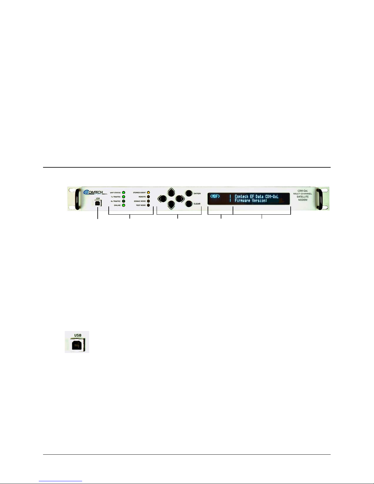
Chapter 5. FRONT PANEL
5.1 Front Panel Overview
USB LED Indicators Keypad VFD Left-Hand VFD Right-Hand
Port Display Area Display Area
Figure 5-1. CDM-Qx/QxL – Front Panel View
The user can fully control and monitor the operation of the CDM-Qx/QxL from the front panel
using the keypad and display. Nested menus are used, which display all available options and
prompt the user to carry out a required action.
Figure 5-1 identifies the key
the sections that follow.
OPERATION
features of the front panel, which are explained in greater detail in
5.1.1 USB Port
This USB Slave connector allows the user to reflash firmware. See Chapter 4. FLASH
UPGRADING for complete information about firmware upgrade procedures for the
CDM-Qx/QxL.
5–1
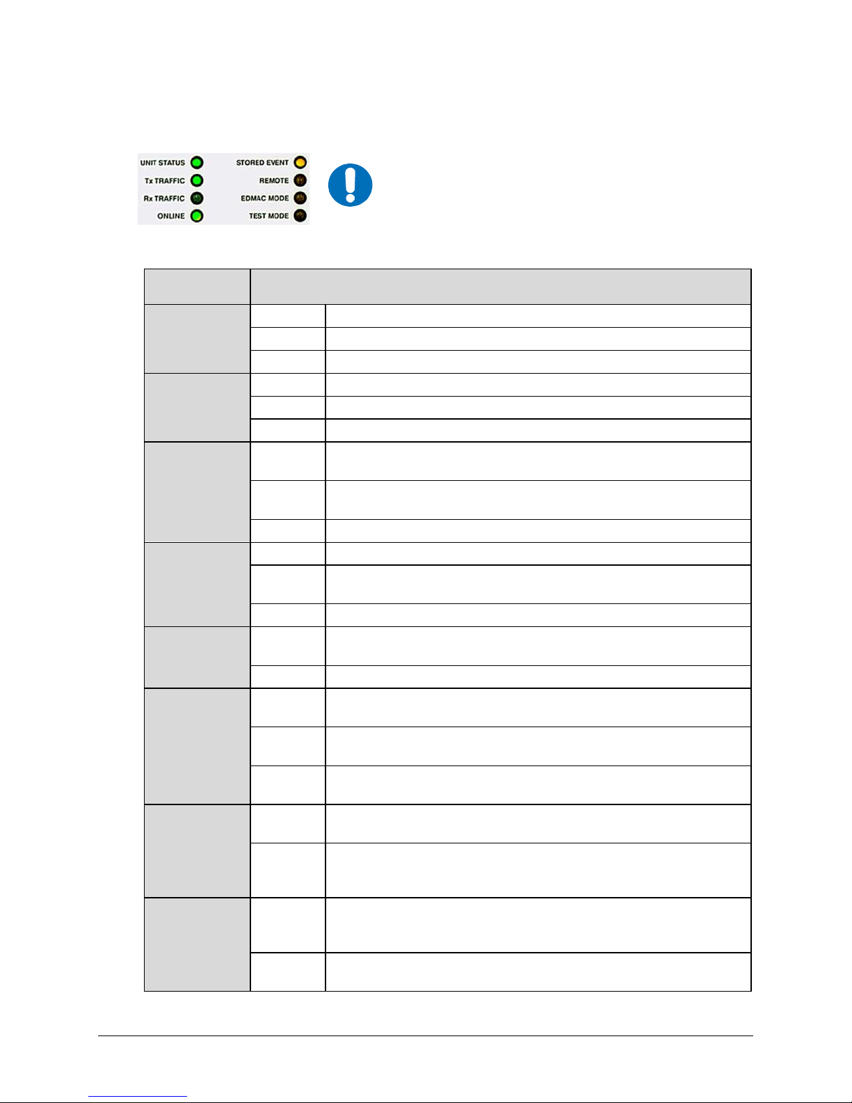
CDM-Qx/QxL Multi-Channel Satellite Modem with DoubleTalk™ Carrier-in-Carrier® Revision 7
Front Panel Operation MN/CDMQX.IOM
5.1.2 LED Indicators
IMPORTANT
In general, the Alarm relay state will reflect the state of the
Front Panel LEDs. For example, if the Unit Status LED is
red, the Unit Alarm relay will be active, etc. The one
exception is the Transmit Traffic relay. This will only be
activated if a Transmit Traffic Fault exists – it does not
reflect the state of the Tx carrier.
The function of the eight front panel LED indicators is as follows:
LED Condition
Red A Unit Fault exists (Example: PSU fault)
Unit Status
Transmit
Traffic
Receive
Traffic
Online
Stored Event
Remote
EDMAC Mode
Test Mode
Green
Green
Off
Note: This LED corresponds to the selected slot, example <TX>.
Green
Off
Note: This LED corresponds to the selected slot, example <RX>.
Green
Off
Note: This LED corresponds to the selected slot, example <RX>.
Orange
Off
Orange
Off
Flashing
Orange
Off
Orange
Off
No Unit Faults
Note: Unit fault does not include Tx or Rx fault.
No Tx Traffic Faults
A Tx Traffic fault exists or the Tx Carrier is in OFF state
No Rx Traffic Faults (demod and Viterbi decoder are locked,
everything is OK)
An Rx Traffic fault exists (the demod may still be OK – check the
fault status of the unit from the Monitor menu).
The Unit is On Line, and carrying traffic
The Unit is Off Line (standby) - forced by externally connected 1:1
or 1:N redundancy system
There is a Stored Event in the log, which can be viewed from the
front panel, or retrieved via the remote control interface
There are no Stored Events
The Unit is in Remote Mode - local monitoring is possible, but no
local control
The Unit is in Local Mode - remote monitoring is possible, but no
remote control
ODU FSK control has been enabled, and there is a
communications fault.
Framing on, EDMAC on, and unit defined as Slave - local
monitoring is possible, but no local control
Either the unit is in Transparent mode (no framing), or the framing
has been selected, but in AUPC-only mode, or EDMAC Master
configuration.
A Test Mode is selected (Example: IF Loopback), or BERT
Generator is turned on, or BERT Monitor is turned on, or Spectrum
Analyzer is turned on.
There is no Test Mode currently selected, BERT Generator is off,
BERT Monitor is off, and spectrum Analyzer is off.
5–2
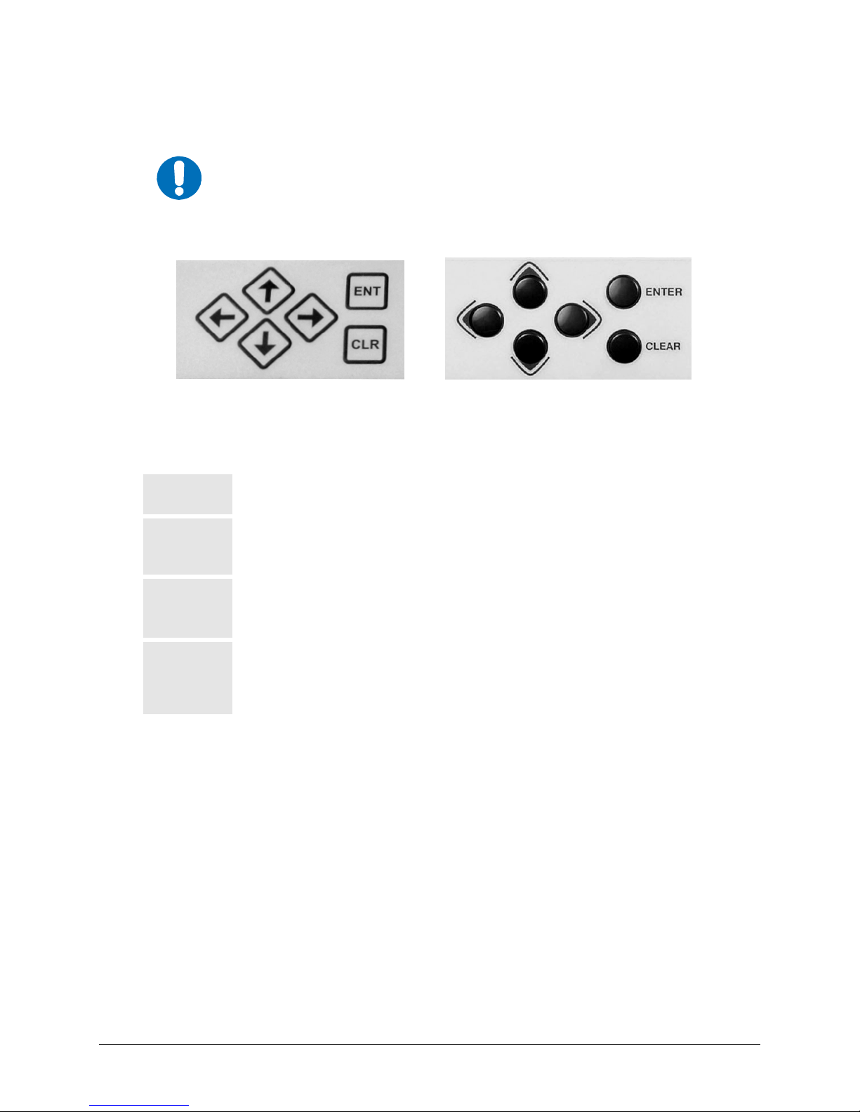
CDM-Qx/QxL Multi-Channel Satellite Modem with DoubleTalk™ Carrier-in-Carrier® Revision 7
Front Panel Operation MN/CDMQX.IOM
5.1.3 Keypad
The keypad has an auto-repeat feature. If a key is held down for more than 1 second,
the key action will repeat, automatically, at the rate of 15 keystrokes per second. This is
particularly useful when editing numeric fields, with many digits, such as frequency or
IMPORTANT
The keypad, in its original and current incarnations, is shown in Figure 5-2:
data rate.
Diamond Keypad (used prior to June 2007) Button Keypad (used as of June 2007)
Figure 5-2. CDM-Qx/QxL Keypad
The function of the keypad is as follows:
ENTER
[ENT]
CLEAR
[CLR]
◄ ►
[←] , [→]
(Left, Right)
▲ ▼
[↑] , [↓]
(Up, Down)
This key is used to select a displayed function or to execute a modem
configuration change.
This key is used to back out of a selection or to cancel a configuration change
that has not been executed using ENTER [ENT]. Pressing CLEAR [CLR]
generally returns the display to the previous selection.
These arrows are used to move to the next selection or to move the cursor
position. Most of the menus (space permitting) include arrow key hints to guide
the user.
These arrows are used primarily to change configuration data (numbers), at the
current cursor position. Occasionally they may be used to scroll through a
number of choices at the current cursor position. Most of the menus (space
permitting) include arrow key hints to guide the user.
5–3

CDM-Qx/QxL Multi-Channel Satellite Modem with DoubleTalk™ Carrier-in-Carrier® Revision 7
Front Panel Operation MN/CDMQX.IOM
5.1.4 Front Panel Vacuum Fluorescent Display (VFD)
The CDM-Qx/QxL features a Vacuum
Fluorescent Display (VFD). The VFD is an
active display showing two lines of 40
characters each. It produces a blue light, the brightness of which can be controlled by the user.
Compared to a Liquid Crystal Display (LCD), it has greatly superior viewing characteristics and
does not suffer problems of viewing angle or contrast.
On most menu screens, the user will observe a flashing solid block cursor, which blinks at a onceper-second rate. This indicates the currently selected item, digit, or field. Where this solid block
cursor would obscure the item being edited (for example, a numeric field) the cursor
automatically changes to an underline cursor.
If the user were to display the same screen for weeks at a time, the display could become ‘burnt’
with this image. To prevent this, the unit has a ‘screen saver’ feature that activates after 1 hour.
The top line of the display will show the Circuit ID (which can be entered by the user) and the
bottom line will show the circuit Eb/No value (if there is a demod and it is locked) followed by
‘Press any key....’. The message moves from right to left across the screen, then wraps around. If
there are multiple circuits, their messages and Eb/No’s will be displayed sequentially. Press any
key to return to the previous screen.
The display is divided into two areas – left-hand and right-hand. The left-hand display area (also
referred to as the slot screen) can be accessed by using the ◄ arrow key if the menu-level is
MAIN, CONFIG, MONITOR, or INFO (and there is more than one installed module present
for selection).
To go back to the right-hand display area (also referred to as the menu screen), just press
or ENTER. Note that, by pressing ENTER selects that plug-in card for menu screen operations.
The functionality of the two display areas is outlined in the sections that follow.
CLEAR
5.1.4.1 VFD – Left-hand Display Area
The left-hand display area (or slot screen) efficiently indicates what is installed into each of the
chassis’ four plug-in slots, and which slot is currently being addressed. The following example
displays four ungrouped plug-ins:
TX TX | (right-hand display area)
<RX> RX | (right-hand display area)
This display indicates modulators in the top slots, and demodulators in the bottom slots. The
orientation of these four indicators serve as a mnemonic for the orientation of the four slots as
viewed from the rear of the chassis – e.g., the left-hand TX displayed on the VFD corresponds
with the top left slot when looking at the chassis rear panel. An empty slot is left blank.
In the above example, the left RX is highlighted, indicating that this is the selected slot. All
monitor functions (including the front panel LEDs) reflect the status of this slot. All parameters
selected from the menu tree while this slot is selected apply either to this slot or to common
functions. The menus for common functions appear redundantly in all four slots. To change slots,
move the cursor to the desired slot, and press
ENTER.
5–4

CDM-Qx/QxL Multi-Channel Satellite Modem with DoubleTalk™ Carrier-in-Carrier® Revision 7
Front Panel Operation MN/CDMQX.IOM
A plug-in device that includes an ‘F’ suffix indicates the presence of an unmasked failure:
TX TXF | (right-hand display area)
<RX> RX | (right-hand display area)
In this example, the upper right transmitter has a fault, the details of which may be viewed using
such menus as Monitor or Alarms.
5.1.4.1.1 Modems
A modulator in a top slot can be grouped with a demodulator in the slot directly below it to form
a modem:
TX <MD> | (right-hand display area)
RX | (right-hand display area)
This example indicates a configuration in the right hand slots (when viewed from the back of the
chassis) grouped together to form a modem. Selecting the slots is the same as with a basic
configuration except that the blank selection slot (below the ‘MD’) is not selectable. When the
modem is selected, the menus display modulator and demodulator functions, and the software
selects the appropriate plug-in for the command.
Two modems can share a modem:
MD MD | (right-hand display area)
| (right-hand display area)
The selected modem is the modulator demodulator pair on the right side of the chassis (when
viewed from the back). When modem is in CnC mode, the brackets (< >) turn into bold characters.
5.1.4.1.2 Redundancy
Modulators and Demodulator modules can be upgraded to operate as redundant units. When
enabled, the module can back up any same-type module installed in one of the chassis’ three
remaining slots. If a modulator and demodulator have redundancy enabled and they are grouped
as a modem, the pair can back up the second modem.
Note: The interface selected for the modules does not have to match the interface type used on
the prime modules.
Three redundancy modes are possible with a modem. Backup devices are notated with a ‘B’
suffix. In a non-modem configuration, the backup device must be installed in Slot #4. If a backup
device has failed, the ‘B’ and ‘F’ suffixes will alternately display.
1:1 redundant modems look similar to the two-modem example. The modems have independent
monitor functions, but configuring the prime modem will also configure the backup modem.
In this example, the backup modem is selected:
MD <MDB> | (right-hand display area)
| (right-hand display area)
1:2 and 1:3 modulators or demodulators look similar to the basic display.
A backup modulator or demodulator will back up all compatible modulators or demodulators in
the chassis designated as primes.
The Online LED, together with the selection bracket (< >), indicate which device is online.
5–5

CDM-Qx/QxL Multi-Channel Satellite Modem with DoubleTalk™ Carrier-in-Carrier® Revision 7
Front Panel Operation MN/CDMQX.IOM
5.1.4.1.3 S pectrum Analyzer
The built-in spectrum analyzer mode is available, accessible via remote control, front panel
operation, or web browser. When it is active, the selected demod will not respond to specific Rx
front panel settings, nor will it carry traffic. Marked with an ‘S’ suffix, it has it is own front panel
menu controls under the
Test menu.
TX TX | (right-hand display area)
<RX> RXS | (right-hand display area)
In this example, the receiver module installed in Slot#4 (bottom right on the VFD and when viewing
the rear panel of the chassis) is being used as a spectrum analyzer. Only one Rx is allowed to enable
spectrum analyzer in a chassis. To view the spectrum, the user needs to access the CDM-Qx Web
Server Interface via a web browser.
5.1.4.2 VFD – Right-Hand Display Area
The right-hand side display area (or menu screen) facilitates operation of the selected installed
device (module) or group (modules).
Note: To group a modulator and demodulator together requires a modulator module to be
installed above a demodulator module; one of the two modules then needs to be selected via the
left-hand display area. Returning to the right-hand display area, the user must select
Group Æ Modem
, then select Group (see Sect. 5.7.1.4 for details).
Config Æ
5.2 Front Panel Operation – Opening Screen
The opening screen is displayed whenever
power is first supplied to the unit. On the
menu screen side of the display, the top line
identifies the unit in use (CDM-Qx for 70/140 MHz operation, CDM-QxL for L-Band operation).
The second line of the menu screen identifies the installed firmware version.
Control of the selected module is determined by the selection made via the left-hand display (slot
screen). The slot screen can be accessed by using the ◄ arrow key if the menu-level is MAIN,
CONFIG, MONITOR, or INFO (and there is more than one installed module present for
selection).
Press any key to go to the Main Menu screen. Table 5-1 outlines the chapter sections and,
subsequently
Note the following:
• V1.X.X ↑ = Original chassis (units typically manufactured prior to July 2008)
running Firmware No. FW/11245.
• V2.1.1
↑ = Upgraded chassis (units typically manufactured from July 2008 to
present) running Firmware No. FW0000107.
, the hierarchal structure of the front panel menu tree.
5–6

CDM-Qx/QxL Multi-Channel Satellite Modem with DoubleTalk™ Carrier-in-Carrier® Revision 7
Front Panel Operation MN/CDMQX.IOM
Table 5-1. Prinicpal Menu Tree
Section Title Remarks
5.2 Opening Screen
5.3 Main Menu
5.4 Config
5.4.1
5.4.2
5.4.3
5.4.4
5.4.5
5.4.6
5.4.7
5.4.8
5.4.9
5.5 Monitor
5.5.1
5.5.2
5.5.3
5.5.4
5.5.5
5.5.6
5.5.7
5.6 Test
5.6.1
5.6.2 Test Æ BIST Select: BERT-Config; BERT-Mon; BERT-Control
5.6.3 Test Æ Spec-Analyzer Select: Center-Freq; Span
5.7 Info
5.8 Save/Load
5.9 Utility
5.9.1 Utility Æ RxBuffer Select to Re-center buffer
5.9.2 Utility Æ Clock Select to edit Real-Time Clock (Time and Date)
5.9.3 Utility Æ Ref Select: Adjust; Warm-up Delay
5.9.4 Utility Æ ID Select to edit Circuit ID
5.9.5 Utility Æ Display Select to adjust VFD brightness
5.9.6 Utility Æ Firmware Select: Update-CPLD; Information; Select
5.9.7 Utility Æ FAST Select: Base; Slot1; Slot2; Slot3; Slot4
Config → Remote
Config → Tx Select: FEC; Mod; Code; Data; Freq; On/Off; Pwr; Scram; Clk; Inv; Txα
Config → Rx
Config → Group
Config → Frame
Config → Interface
Config → Ref
Config → Mask
Config → ODU
(CDM-QxL only)
Monitor → Alarms
Monitor → Rx-Params Select: Eb/No, BER, ΔF, BUF, RSL
Monitor → Event-Log
Monitor → Stats
Monitor → AUPC
(CDM-QxL only)
Monitor → CnC Carrier in Carrier® (CnC) indicates as Active or N ot Active
Monitor → ODU
(CDM-QxL only)
Test → Mode
Select: Config; Monitor; Test; Info; Save/Load; Utiity
Select: Remote; Tx; Rx; Group; Frame; Interface; Ref; Mask; (CDM-QxL only) ODU
Select: Local; Serial; Ethernet
Select: FEC; Demod; Code; Data; Freq; Acq; Descram; Buf; Inv; Misc; CNC
Select: Modem; Redundancy
Select: Unframed; EDMAC; EDMAC-2; D&I++
Select: RS422; V.35; RS232; HSSI; G.703; QDI; None
Select: Internal; 10MHz
Select: Transmit; Receive; Reference; (CDM-QxL only) BUC; (CDM-QxL only) LNB
Select: BUC; LNB
Select: Alarms; Rx-Params; Event-Log; Stats; AUPC; CNC; (CDM-QxL only) ODU
Select: Transmit; Receive; Unit; (CDM-QxL only) ODU
Select: View; Clear-All
Select: View; Clear-All; Config
Framing is required for AUPC Monitor - Select: Remote Eb/No; Tx Power Increase
Select: ODU; LNB
Select: Mode; BIST; Spec-Analyzer
Select: Norm; IF Loop; Dig Loop; I/O Loop; RF Loop; Tx-CW; Tx-1,0
Select: Rem; Tx; Rx; Buffer; Frame; Interface; Mask; Ref; ID
Select: Save; Load
Select: RxBuffer; Clock; Ref; ID; Display; Firmware; FAST
For the purpose of clarity, only the right-hand display area (or menu screen) is visually depicted
throughout the remainder of this chapter.
5–7

CDM-Qx/QxL Multi-Channel Satellite Modem with DoubleTalk™ Carrier-in-Carrier® Revision 7
Front Panel Operation MN/CDMQX.IOM
5.3 MAIN MENU Screen
MAIN MENU: Config Monitor
Test Info Save/Load Utility
Use the ◄ ► arrow keys to select from the choices shown on this top-level selection screen, then
ENTER. The following table identifies the menu branch, its content section in this chapter,
press
and the functional description of each branch:
Menu Branch Sect Description
Config 5.4 (Configuration) Permits the user to fully configure the unit.
Monitor 5.5
Test 5.6
Info 5.7
Save/Load 5.8
Utility 5.9
The actual choices displayed in the submenus may vary according to which
FAST options have been enabled. Where a FAST option affects a menu, this
IMPORTANT
is shown in the descriptive text.
Permits the user to monitor the current status of the modem and view
the log of stored events for the modem.
Permits the user to configure the modem into one of several Test
modes, and configures/monitors the BER Tester.
(Information) Permits the user to view information on the modem,
without having to go into the Configuration screens.
(Store/Load) Permits the user to store and retrieve up to 10 different
modem configurations.
Permits the user to perform miscellaneous functions, such as setting the
Real-Time Clock, adjusting the display brightness, etc.
5–8

CDM-Qx/QxL Multi-Channel Satellite Modem with DoubleTalk™ Carrier-in-Carrier® Revision 7
Front Panel Operation MN/CDMQX.IOM
5.4 (MAIN MENU:) Config (Configuration)
CONFIG: Remote Tx Rx Group
Frame Interface Ref Mask ODU
Use the ◄ ► arrow keys to select from the submenu choices shown, then press ENTER. The
submenus available from the Configuration menu are as follows:
Submenu Sect Description
(Remote Control) This menu sub-branch permits the user to define
whether the unit is being controlled locally, or remotely.
Remote 5.4.1
Tx 5.4.2
Rx 5.4.3
Group 5.4.4
Frame 5.4.5
Interface 5.4.6
Ref 5.4.7
NOTE: The unit may be monitored over the remote control bus at any time.
When in Local mode, however, configuration parameters may only be
changed through the front panel. Conversely, when in Remote mode, the
unit may be monitored from the front panel, but configuration parameters
may only be changed via the remote control bus.
(Transmit) This menu sub-branch permits the user to define, on a
parameter-by-parameter basis, the transmit configuration of the unit.
(Receive) This menu sub-branch permits the user to define, on a
parameter-by-parameter basis, the receive configuration of the unit.
This menu sub-branch permits the user to group a vertically aligned
modulator and demodulator into a modem, or to group any compatible
plug-ins for redundancy.
This menu sub-branch permits the user to define if the unit should operate
in a transparent mode (no framing) or in a framed mode. In the framed
mode (EDMAC), an overhead of 5% is added to the rate transmitted over
the satellite so that M&C information may be passed to the distant end.
(Interface) This menu sub-branch permits the user to define which
electrical interface type is active at the data connectors.
(Reference) This menu sub-branch permits the user to define whether the
unit should use its own internal 10MHz reference, or phase lock to an
externally applied reference, and if so, at what frequency. If the internal
reference is selected, it can optionally drive the connector.
Mask 5.4.8
ODU
(L-Band
unit only)
5.4.9
5–9
This menu sub-branch permits the user to mask certain traffic alarms,
which may cause problems to the user. As an example, certain
multiplexers use ‘all ones’ as an idle pattern. However, by convention, the
‘all ones’ condition is taken to be the Alarm Indication Signal (AIS). The
CDM-Qx monitors for the AIS condition, and if desired, this alarm may be
masked.
(Outdoor Unit) This menu sub-branch permits the user to configure
externally connected Low-noise Block Down Converter (LNB) and/or Block
Up Converter (BUC) for L-Band units.

CDM-Qx/QxL Multi-Channel Satellite Modem with DoubleTalk™ Carrier-in-Carrier® Revision 7
Front Panel Operation MN/CDMQX.IOM
5.4.1 CONFIG: Remote
Remote Control Entry: Local
Serial Ethernet (◄ ►,ENT)
Select Local, Serial, or Ethernet using the ◄ ► arrow keys, then press ENTER.
5.4.1.1 CONFIG: Remote Æ Local
If CONFIG: Remote Æ Local is selected, remote control is disabled, although remote monitoring
is still possible.
5.4.1.2 CONFIG: Remote Æ Serial
Remote Serial Config:
Interface Baudrate (◄ ►,ENT)
Select Interface or Baudrate using the ◄ ► arrow keys, then press ENTER.
CONFIG: Remote Æ Serial Æ Interface
M&C Serial Interface: RS232
RS485-2W RS485-4W (◄ ►,ENT
From the Interface submenu, the user is further prompted to enter the bus address. Select
RS232, RS485-2W (2-wire), or RS485-4W (4-wire) using the ◄ ► arrow keys, then press
ENTER.
CONFIG: Remote Æ Serial Æ Interface Æ RS232
In RS-232 Mode, Serial Bus
Base Address is fixed @ 0000
Note that the bus base address in RS-232 mode is fixed and cannot be edited.
CONFIG: Remote Æ Serial Æ Interface Æ RS485(-2W, -4W)
Edit RS-485 Serial Bus Base
Address: 0245 (◄ ►,▲▼,ENT)
If either RS-485 mode is selected, edit the RS-485 bus address of this unit by first
selecting the digit to be edited using the
digit to be edited by using the dc arrow keys. The valid range of addresses is from 1 to
9999. Press ENTER when done.
ef arrow keys, then change the value of the
CONFIG: Remote Æ Serial Æ Baudrate
M&C Serial Bus Baud Rate:
19200 Baud (▲ ▼,ENT)
Using the cd arrow keys, edit the baudrate of the remote control bus connected locally to
the M&C computer. Values of 2400, 4800, 9600, 19200, 38400, and 57600 baud are
5–10

CDM-Qx/QxL Multi-Channel Satellite Modem with DoubleTalk™ Carrier-in-Carrier® Revision 7
Front Panel Operation MN/CDMQX.IOM
possible. Press ENTER when done. Note that the asynchronous character format is FIXED
at 8-N-1: 8 data bits, 1 stop bit, no parity.)
5.4.1.3 CONFIG: Remote Æ Ethernet
Ethernet Config: (◄ ►,ENT)
Gateway Address MAC SNMP
Select Gateway, Address, MAC, or SNMP using the ◄ ► arrow keys, then press ENTER.
CONFIG: Remote Æ Ethernet Æ Gateway
M&C Ethernet IP Gateway:
192.128.001.001 (◄ ► ▲ ▼,ENT)
Edit the IP Gateway Address for the Ethernet M&C port for this unit by first selecting the digit
to be edited using the
the dc arrow keys. Press ENTER when done.
ef arrow keys, then change the value of the digit to be edited by using
CONFIG: Remote Æ Ethernet Æ Address
M&C Ether IP Address/Range:
192.168.001.001/24(◄ ►,▲ ▼,ENT)
Edit the IP Address and Range for the Ethernet M&C port for this unit by first selecting the
digit to be edited using the
using the dc arrow keys. Press ENTER when done.
ef arrow keys, then change the value of the digit to be edited by
CONFIG: Remote Æ Ethernet Æ MAC
M&C Port MAC Address:
00-06-B0-00-00-D5
As shown in this example, this read-only window displays the factory program MAC address
for the Ethernet management interface.
CONFIG: Remote Æ Ethernet Æ SNMP
SNMP: Communities Traps
(◄ ►,ENT)
Select Communities or Traps using the ◄ ► arrow keys, then press ENTER.
CONFIG: Remote Æ Ethernet Æ SNMP Æ Communities
SNMP Communities:
Read Write (◄ ►,ENT)
Select Read or Write using the ◄ ► arrow keys, then press ENTER.
CONFIG: Remote Æ Ethernet Æ SNMP Æ Communities Æ Read
Read Community: (◄ ► ▲ ▼,ENT)
public
5–11

CDM-Qx/QxL Multi-Channel Satellite Modem with DoubleTalk™ Carrier-in-Carrier® Revision 7
Front Panel Operation MN/CDMQX.IOM
CONFIG: Remote Æ Ethernet Æ SNMP Æ Communities Æ Write
Write Community: (◄ ► ▲ ▼,ENT)
private
Edit either the SNMP Read or Write Community string by first selecting the
character to be edited using the
edited by using the dc arrow keys. Only the first 20 characters on the bottom line
are available.
All printable ASCII characters are available with the exception of the backslash ( \
ASCII code 92) and the tilde (~ ASCII code 126). Once the string has been
composed, press
Community string upon entering.
ENTER. All trailing spaces are removed from the Read or Write
ef arrow keys, then change the character to be
CONFIG: Remote Æ Ethernet Æ SNMP Æ Traps
Traps: Community Version
IP Addr#1 IP Addr#2 (◄ ►,ENT)
Select Community, Version, IP Addr#1, or IP Addr#2 using the ◄ ► arrow keys,
then press
ENTER. Selecting Read displays the following submenu:
CONFIG: Remote Æ Ethernet Æ SNMP Æ T rap s Æ Community
Trap Community: (◄ ► ▲ ▼,ENT)
comtech
Edit the Trap Community string by first selecting the character to be edited using the
ef arrow keys, then change the character to be edited by using the dc arrow keys.
Only the first 20 characters on the bottom line are available.
All printable ASCII characters are available with the exception of the backslash ( \
ASCII code 92) and the tilde (~ ASCII code 126). Once the string has been
composed, press
upon entering.
ENTER. All trailing spaces are removed from the Community string
CONFIG: Remote Æ Ethernet Æ SNMP Æ T rap s Æ V ersion
Trap Version: (◄ ►,ENT)
SNMPv1 SNMPv2
Select SNMPv1 or SNMPv2 using the ◄ ► arrow keys, then press ENTER.
CONFIG: Remote Æ Ethernet Æ SNMP Æ T rap s Æ IP Addr#X
Trap IP Addr#X: (◄ ► ▲ ▼,ENT)
000.000.000.000
Where ‘X’ designates the menu selection as IP Addr#1 -or- IP Addr#2: These two
IP Addresses are Trap Destination IP Addresses. Edit the IP Address by first
selecting the digit to be edited using the
digit to be edited by using the dc arrow keys. Press ENTER when done.
Note: If both Trap IP Address are set to 000.000.000.000, it means Trap is disabled.
5–12
ef arrow keys, then change the value of the

CDM-Qx/QxL Multi-Channel Satellite Modem with DoubleTalk™ Carrier-in-Carrier® Revision 7
Front Panel Operation MN/CDMQX.IOM
5.4.2 CONFIG: Tx (Transmit)
Tx: FEC Mod Code Data Freq
On/Off Pwr Scram Clk Inv Txα
Select FEC, Mod, Code, Data, Freq, On/Off, Pwr, Scram, Clk, Inv, or Txα using the ◄ ►
arrow keys, then press
is described briefly as follows:
ENTER. The user will then be taken to a further submenu. Each selection
FEC
Mod
Code
Data
Freq
On/Off
Pwr
Scram (Scrambler) This submenu permits the user to select whether or not data scrambling is used.
Clk
Inv
(Forward Error Correction) This submenu permits the user to select the method of FEC
used for transmission (Viterbi, TPC, etc). FEC type takes the highest configuration priority.
(Modulation) This submenu permits the user to select the modulation type used for
transmission (BPSK, QPSK, 8-PSK, etc.). The available choice of modulation will depend on
the FEC type chosen.
(FEC Code Rate) This submenu permits the user to select the FEC Code Rate used for
transmission (Rate 1/2, Rate 3/4, etc). The available choice of Code Rate will depend on both
the FEC type and Modulation type selected.
(Data Rate) This submenu permits the user to select the transmit data rate, in steps of 1 bps.
The choice of data rate will depend on the FEC type, Modulation type, and Code Rate
selected.
(Frequency) This submenu permits the user to select the transmit frequency, from 950 MHz
to 1950 MHz, in steps of 100Hz for L-Band units, or from 50 MHz to 90 MHz and from 100
MHz to 180 MHz for 70/140MHz units.
This submenu permits the user to control the output state of the transmit carrier.
(Output Power level) This submenu permits the user to control the output level of transmit
carrier, either manually, or using the AUPC (Automatic Uplink Power Control) feature.
(Clock Source) This submenu permits the user to select the clock source for transmission.
This can be from the internal source, from an external source, or from the distant-end of the
satellite link (loop timed).
(Inversion) This submenu permits the user to invert the sense of the transmitted spectrum,
or to invert the sense of the transmitted baseband data or data clock
Txα (α-Factor) This permits the user to select the modulator’s roll-off factor either 20% or 35%.
The FEC type takes the highest configuration priority, and the selection
here depends on what, if any, optional plug-in Codecs are installed. The
choice of FEC type then determines what modulation types, code rates,
IMPORTANT
and data rates are available. The order of hierarchy is therefore:
FEC type ► Modulation type ► Code Rate ► Data Rate
(Highest) (Lowest)
If the user changes a parameter within this hierarchy, the other parameters may become invalid.
In this case, the software will change those other parameters, in order to maintain a valid
configuration at all times.
Example: Suppose the user has selected Viterbi + Reed Solomon, QPSK, Rate 1/2. Now, the
user changes the modulation type from QPSK to 16-QAM. In this case, Rate 1/2 is no longer a
valid code rate, and so it will be automatically changed to the nearest valid code rate (Rate 3/4).
Detailed descriptions for each of the Tx configuration submenus follow.
5–13
CDM-Qx/QxL Multi-Channel Satellite Modem with DoubleTalk™ Carrier-in-Carrier® Revision 7
Front Panel Operation MN/CDMQX.IOM
5.4.2.1 CONFIG: Tx Æ FEC
Tx FEC: Vit Vit+RS TCM+RS
TPC (◄ ►,ENT)
For the Transmit FEC type, select Vit, Vit+RS, TCM+RS, or TPC using the ◄ ► arrow keys,
then press
ENTER.
All possible choices are presented at all times. If an option is not installed (either
Hardware, or FAST) or not valid, the ◄ ► arrow keys will force the cursor to
skip past the unavailable choice.
Note the following:
FEC TYPE RULES COMMENT
Vit (Viterbi)
Vit+RS (Viterbi +Concatenated
Reed-Solomon)
TCM+RS (Trellis Coded Modulation
+ Concatenated Reed-Solomon)
TPC (Turbo)
Selecting VIT+RS or TCM+RS displays the following submenu:
Tx Rs (n/k) (◄ ►,ENT)
IESS-310 network (219/201)
5.4.2.2 CONFIG: Tx Æ Mod
Always valid.
Always valid.
Only if 8-PSK FAST is
enabled.
If the TPC codec is installed
and Data Rate FAST option
is enabled.
Fixed at 8-PSK and Rate 2/3.
Modulation: BPSK QPSK 8-PSK
16-QAM (◄ ►,ENT)
For the Transmit Modulation Scheme, select BPSK, QPSK, 8-PSK, or 16-QAM using the ◄ ►
arrow keys, then press ENTER.
Note the following:
CASE RULES
BPSK
QPSK
8-PSK
16-QAM
5–14
All possible choices are presented at all times. If an option is not installed (either
Hardware, or FAST) or not valid, the ◄ ► arrow keys will force the cursor to
skip past the unavailable choice.
Valid for all FEC types except TCM+R-S
Valid for all FEC types except TCM+R-S
Valid for TCM+R-S, TPC (Turbo) requires 8-PSK FAST option
Valid for Viterbi + R-S, TPC (Turbo) requires 16-QAM FAST option

CDM-Qx/QxL Multi-Channel Satellite Modem with DoubleTalk™ Carrier-in-Carrier® Revision 7
Front Panel Operation MN/CDMQX.IOM
5.4.2.3 CONFIG: Tx Æ Code
Tx Code Rate: 5/16 21/44 1/2
2/3 3/4 7/8 17/18 (◄ ►)
For the Transmit Code Rate, select 5/16, 21/44, 1/2, 2/3, 3/4, 7/8, or 17/18 using the ◄ ► arrow
keys, then press
CASE RULES
ENTER. Note the following:
Valid for BPSK and Turbo
Valid for BPSK, QPSK and Turbo
Valid for BPSK, QPSK, Viterbi, Viterbi+R-S
Valid for TCM+R-S only (8-PSK)
Valid for QPSK, 8-PSK, and 16-QAM
Valid for QPSK, 8-PSK, and 16-QAM
Valid for QPSK, 8-PSK , and Turbo
5/16
21/44
1/2
2/3
3/4
7/8
17/18
All possible choices are presented at all times. If an option is not installed (either
Hardware, or FAST) or not valid, the ◄ ► arrow keys will force the cursor to
skip past the unavailable choice.
5.4.2.4 CONFIG: Tx Æ Data
Tx Data Rate: 05000.000kbps
Sym:02500.000ksps
For the Transmit Data Rate, select 5/16, 21/44, 1/2, 2/3, 3/4, 7/8, or 17/18 using the ◄ ► arrow
keys, then press
Note: In Quad Drop & Insert (QDI) mode, these data rates are read-only; otherwise, they are
read/write. The data rate will be the sum of the tributary rates for all ports. This also will show
the calculated symbol rate and Nx64kbps (where N=001 to 128).
IMPORTANT
ENTER.
The overall range of data rates is from 32 to 20000 kbps. The overall range of
symbol rates is up to 10000 ksps. The minimum data rate is set to 32 kbps only
for BPSK and QPSK, and the maximum data rates are dependent on modulation
type and FEC encoder rate. If the user changes the modulation or FEC, and the
currently selected data rate can no longer be supported, the data rate will be
adjusted automatically, up or down, keeping the symbol rate constant. The
bottom line of the display shows the symbol rate, based on FEC type,
modulation, FEC Code Rate, and Data Rate. The valid ranges of data rate are
shown in the table that follows on the next page.
5–15

CDM-Qx/QxL Multi-Channel Satellite Modem with DoubleTalk™ Carrier-in-Carrier® Revision 7
p
p
p
p
p
Front Panel Operation MN/CDMQX.IOM
Note the following:
FEC Type Modulation Code Rate Data Rate Range EDMAC limited?
BPSK Rate 1/2 32 kb
Vit (Viterbi)
Vit+RS (Viterbi
+Concatenated ReedSolomon)
TCM+RS (Trellis Coded
Modulation +
Concatenated ReedSolomon)
TPC (Turbo)
QPSK
BPSK Rate 1/2 32 kbps to 4.5 Mbps
QPSK
16-QAM
8-PSK Rate 2/3 232.7 kbps to 18.3 Mbps
BPSK
QPSK
8-PSK
16-QAM
Rate 1/2 32 kbps to 10 Mbps
Rate 3/4 32 kbps to 15 Mbps
Rate 7/8 32 kbps to 17.5 Mbps
Rate 1/2 32 kbps to 9.1 Mbps
Rate 3/4 32 kbps to 13.7 Mbps
Rate 7/8 32 kbps to 16 Mbps
Rate 3/4 349.1 kb
Rate 7/8 407.3 kbps to 20 Mbps
Rate 5/16 32 kb
Rate 21/44 32 kbps to 4.7 Mbps
Rate 21/44 32 kb
Rate 3/4 32 kbps to 15 Mbps
Rate 7/8 32 kbps to 17.5 Mbps
Rate 17/18 32 kbps to 18.888 Mbps
Rate 3/4 288 kbps to 20 Mbps
Rate 7/8 336 kbps to 20 Mbps
Rate 17/18 362.7 kbps to 20 Mbps
Rate 3/4 384 kb
Rate 7/8 448 kbps to 20 Mbps
Important Note: Where noted in the table above, if EDMAC framing is employed, the upper
data rate will be reduced by 5% for data rates up to 2.048 Mbps, and by 1.6% for data rates
above 2.048 Mbps, where EDMAC2 framing is used, or for Rate 21/44 BPSK/QPSK Turbo, or
Rate 5/16 BPSK Turbo.
s to 5 Mbps
s to 20 Mbps
s to 3.1 Mbps
s to 9.5 Mbps
s to 20 Mbps
Yes – see
IMPORTANT
NOTE (below)
Yes – see
IMPORTANT
NOTE (below)
Yes – see
IMPORTANT
NOTE (below)
Yes – see
IMPORTANT
NOTE (below)
No
5.4.2.5 CONFIG: Tx Æ Freq
Tx IF Freq: 1156.3456 MHz
(◄ ►,▲ ▼,ENT)
For the Transmit IF Frequency, the range of frequencies depends upon the plug-in module – the
preceeding example shows the L-Band version of modem. Edit the Transmit IF Frequency by
first using the
changed using the
When using the ODU Æ BUC menus, if the user has selected a BUC LO frequency other than
zero, and has defined whether the mix is high side or low side, the display will be modified as
shown below, to include the calculated Transmit RF frequency of the modem/BUC combination:
Tx IF Freq: 1156.3456 MHz
RF=14156.3456 (◄ ►▲ ▼ ENT)
As the Tx IF frequency is edited, the RF frequency will automatically be updated.
5–16
W X arrow keys to select the digit to be edited; the value of the digit is then
ST arrow keys. Press ENTER when done.

CDM-Qx/QxL Multi-Channel Satellite Modem with DoubleTalk™ Carrier-in-Carrier® Revision 7
Front Panel Operation MN/CDMQX.IOM
5.4.2.6 CONFIG: Tx Æ On/Off
Tx Output State: On Off
RxTxInhibit Common (◄ ►,ENT)
For the Transmit On./Off Control (Output State), select On, Off, RxTxInhibit, or Common
using the W X arrow keys, then press
When Rx-Tx Inhibit (RTI) is selected, it prevents the TX carrier from being transmitted until the
demodulator is locked.
To avoid the Tx Carrier from being turned off when the demodulator loses lock for a very short
period of time, the demodulator must be unlocked continuously for a period of 10 seconds before
the transmit carrier is inhibited. This time interval is fixed and is not user-changeable.
Having this feature enabled does not affect the internal IF Loopback feature.
But, please be aware that if an external IF Loopback is attempted (connecting
an external cable from the Tx IF output to the Rx IF input), then this will not
IMPORTANT
work! (The Tx carrier cannot turn on until the demod is locked, and the demod
cannot lock, because the TX output is off. The net result is that the demod will
not lock, and the Tx carrier will not turn on. USE THE RTI FEATURE WITH
EXTREME CARE!
ENTER.
CONFIG: Tx Æ On/Off Æ Common
Tx Common Output State:
Off On (◄ ► ENT)
For master control of all modulators – i.e., the complete transmit path – select Off or On using
the ◄ ► arrow keys, then press
5.4.2.7 CONFIG: Tx Æ PWR
Output Power Level Mode:
Manual AUPC (◄ ►,ENT)
To set the Transmit Power Level Mode, select either Manual or AUPC using the ◄ ► arrow
keys, then press
ENTER.
CONFIG: Tx Æ Pwr Æ Manual
Tx Output Power Level:
-03.9 dBm (◄ ►, ▲ ▼,ENT)
Edit the Transmit Output Power Level by first using the W X arrow keys to select the digit
to be edited; the value of the digit is then changed using the
when done.
ENTER.
ST arrow keys. Press ENTER
CONFIG: Tx Æ Pwr Æ AUPC
Selecting AUPC without Framed Mode selected results in display of the following message:
Warning! AUPC needs
Framed Mode (ENT or CLR)
5–17

CDM-Qx/QxL Multi-Channel Satellite Modem with DoubleTalk™ Carrier-in-Carrier® Revision 7
Front Panel Operation MN/CDMQX.IOM
Press either ENTER or CLEAR to return to the previous menu (with Manual selected).
With Framed Mode properly configured, selecting AUPC results in display of the following
submenu:
Target-Eb/No Max-Range Alarm
DemodUnlock (◄ ►,ENT)
Select Target EbNo , Max-Range, Alarm, or DemodUnlock using the W X arrow keys,
then press
ENTER.
CONFIG: Tx Æ Pwr Æ AUPC Æ Target-Eb/No
Remote Demod - Target Eb/No
Min Eb/No:9.9dB (◄ ►, ▲ ▼,ENT)
Edit the Transmit AUPC Target Eb/No value by first using the W X arrow keys to
select the digit to be edited; the value of the digit is then changed using the
keys. The default value is 3.0 dB; the upper limit is 9.9 dB. Press
ENTER when done.
ST arrow
CONFIG: Tx Æ Pwr Æ AUPC Æ Max-Range
Maximum-permitted Power
increase: 01dB (▲ ▼,ENT)
Edit the Transmit AUPC Maximum Permitted Power Increase value (when in AUPC
mode) by first using the
digit is then changed using the
is 9 dB. Press
ENTER when done.
W X arrow keys to select the digit to be edited; the value of the
ST arrow keys. The default value is 1 dB; the upper limit
CONFIG: Tx Æ Pwr Æ AUPC Æ Alarm
Action when max Tx Power
reached: None TxAlarm (◄ ►,ENT)
To set the action that will occur if the AUPC causes the maximum output power level to be
reached, select None or TxAlarm using the
W X arrow keys, then press ENTER.
CONFIG: Tx Æ Pwr Æ AUPC Æ DemodUnlock
Action when Remote Demod
unlocks: Nom-Pwr Max-Pwr
To select the action that will occur if the remote demod is unlocked, using the W X arrow
keys, select Nom-Pwr (Nomimal Power, where the output level will revert to the nominal
power level that was set under Manual) or Max-Pwr (Maximum Power, where the output
level will change to the maximum permitted). Press
ENTER when done.
5–18

CDM-Qx/QxL Multi-Channel Satellite Modem with DoubleTalk™ Carrier-in-Carrier® Revision 7
Front Panel Operation MN/CDMQX.IOM
5.4.2.8 CONFIG: Tx Æ Scram
Scrambling: Default-On
IESS-315-On Off (◄ ►,ENT)
To set the Transmit Scrambling mode, select Default-On, IESS-315-On, or Off using the ◄ ►
arrow keys, then press ENTER. Note the following:
Default-On
IESS-315-On
Off
The appropriate scrambler type is automatically selected
This only applies when Turbo is installed and has been selected as the FEC type
No scrambling
Scrambler Selection Notes:
1. If CnC is enabled, the V.35 scrambler is always used in order to suppress framing
artifacts.
2. As noted previously, all options are displayed all of the time, but the ◄ ► arrow keys
will force the cursor to skip past an unavailable choice.
The default scrambler types are as follows:
IMPORTANT
Viterbi, no framing: ITU V.35 (Intelsat variant)
Viterbi, EDMAC frame: Comtech proprietary, frame synchronized
Viterbi + R-S or TCM/R-S: Per IESS-308, frame synchronized
TPC: Comtech proprietary, frame synchronized
CnC: ITU V.35 (Intelsat variant) – overrides other settings
5.4.2.9 CONFIG: Tx Æ Clk
Tx Clocking Mode: Int Ext
Loop-Timed ExtLoop (◄ ►,ENT)
To set the Transmit Clocking Source, select Int, Ext, Loop-Timed , or ExtLoop using the ◄ ►
arrow keys, then press
Int
Ext
Loop-Timed
ExtLoop
5–19
ENTER. Note the following:
(Internal) Indicates that the CDM-QX will supply a clock to the DTE, which is derived
from its internal high-stability source.
(External ) Indicates that the CDM-QX expects to receive a clock from the DTE, to
which the unit can phase-lock its internal circuits. (If G.703 is selected as the Interface
type, the software will force the clock mode to External.)
Indicates that the transmit timing source should be the receive clock, from the
direction of the satellite. This is a useful mode, in that no external connection needs
to be made in this mode. If the demodulator loses lock, or if there is no receive signal
present, the internal clock is substituted. Note also that this mode will work even with
asymmetric Rx and Tx data rates.
(External Loop) Indicates that the CDM-Qx expects to receive a clock from the DTE,
which is derived from the received clock from the direction of the satellite. This is
useful in CnC mode with G.703 interface wherein the remote station is relying on a
centralized clock from the hub station.

CDM-Qx/QxL Multi-Channel Satellite Modem with DoubleTalk™ Carrier-in-Carrier® Revision 7
Front Panel Operation MN/CDMQX.IOM
5.4.2.10 CONFIG: Tx Æ Inv
Tx Inversion functions:
Spectrum Data Clock (◄ ►,ENT)
To set the Transmit Inversion Functions, select Spectrum, Data, or Clock using the ◄ ► arrow
keys, then press
ENTER.
CONFIG: Tx Æ Inv Æ Spectrum
Tx Spectral Inversion:
Normal Inverted (◄ ►,ENT)
Select Normal or Inverted using the ◄ ► arrow keys, then press ENTER.
CONFIG: Tx Æ Inv Æ Data
Tx Data Sense:
Normal Inverted (◄ ►,ENT)
Select Normal or Inverted using the ◄ ► arrow keys, then press ENTER.
CONFIG: Tx Æ Inv Æ Clock
Tx Clock Inversion:
Normal Inverted (◄ ►,ENT)
Select Normal or Inverted using the ◄ ► arrow keys, then press ENTER.
5.4.2.11 CONFIG: Tx Æ Txα
Tx Roll-off: 20% 35%
(◄ ►,ENT)
To set the Transmit Roll-off (α) Factor, select 20% or 35% using the ◄ ► arrow keys, then
ENTER. Note that the default is 35%.
press
5–20

CDM-Qx/QxL Multi-Channel Satellite Modem with DoubleTalk™ Carrier-in-Carrier® Revision 7
Front Panel Operation MN/CDMQX.IOM
5.4.3 CONFIG: Rx (Receive)
Rx: FEC Demod Code Data Freq
Acq Descram Buf Inv Misc CnC
Select FEC, Demod, Code, Data, Freq, Acq, Descram, Buf, Inv, Misc, or CnC using the ◄ ►
arrow keys, then press
described briefly as follows:
ENTER. The user will then be taken to a further submenu. Each selection is
FEC
Demod
Code
Data
Freq
Acq
Descram
Buf
Inv
Misc
(Forward Error Correction) This submenu permits the user to select the method of FEC
used for reception (Viterbi, TPC, etc). FEC type takes the highest configuration priority.
(Demodulation) This submenu permits the user to select the modulation type used for
reception (BPSK, QPSK, 8-PSK, etc.). The available choice of modulation will depend on
the FEC type chosen.
(FEC Code Rate) This submenu permits the user to select the FEC Code Rate used for
reception (Rate 1/2, Rate 3/4, etc). The available choice of Code Rate will depend on both
the FEC type and Demodulation type selected.
(Data Rate) This submenu permits the user to select the receive data rate, in steps of 1
bps. The choice of data rate will depend on the FEC type, Demodulation type, and Code
Rate selected.
(Frequency) This submenu permits the user to select the receive frequency, from 950 MHz
to 1950 MHz, in steps of 100Hz for L-Band units, or from 50 MHz to 90 MHz and from 100
MHz to 180 MHz for 70/140MHz units.
(Acquisition) This submenu permits the user to determine the amount of frequency uncertainty the
demodulator will search over in order to find and lock to an incoming carrier.
(Descrambler) This submenu permits the user to select whether or not data descrambling
is used.
(Buffer) This submenu permits the user to select whether or not the Plesiochronous/
Doppler buffer is used, and if so, the size of that buffer.
(Inversion) This submenu permits the user to invert the sense of the received spectrum, or
to invert the sense of the received baseband data.
(Miscellaneous) This submenu will allow the user to select Eb/No Alarm Threshold (EbNo)
and Rx roll-off (alpha) factor Rxα.
CnC
(Carrier-in-Carrier®) This submenu allows the user to set-up the CnC parameters.
The FEC type takes the highest configuration priority, and the selection here
depends on what, if any, optional plug-in Codecs are installed. The choice of
FEC type then determines what demodulation types, code rates, and data
IMPORTANT
rates are available. The order of hierarchy is therefore:
FEC type ► Demodulation type ► Code Rate ► Data Rate
(Highest) (Lowest)
If the user changes a parameter within this hierarchy, the other parameters may become invalid.
In this case, the software will change those other parameters, in order to maintain a valid
configuration at all times.
Example: Suppose the user has selected Viterbi + Reed Solomon, QPSK, Rate 1/2. Now, the
user changes the demodulation type from QPSK to 16-QAM. In this case, Rate 1/2 is no longer a
valid code rate, and so it will be automatically changed to the nearest valid code rate (Rate 3/4).
Detailed descriptions for each of the Rx configuration submenus follow.
5–21

CDM-Qx/QxL Multi-Channel Satellite Modem with DoubleTalk™ Carrier-in-Carrier® Revision 7
Front Panel Operation MN/CDMQX.IOM
5.4.3.1 CONFIG: Rx Æ FEC
Rx FEC: Vit Vit+RS TCM+RS
TPC (◄ ►,ENT)
For the Transmit FEC type, select Vit, Vit+RS, TCM+RS, or TPC using the ◄ ► arrow keys,
then press
ENTER.
All possible choices are presented at all times. If an option is not installed (either
Hardware, or FAST) or not valid, the ◄ ► arrow keys will force the cursor to
skip past the unavailable choice.
Note the following:
FEC TYPE RULES COMMENT
Vit (Viterbi)
Vit+RS (Viterbi +Concatenated
Reed-Solomon)
TCM+RS (Trellis Coded Modulation
+ Concatenated Reed-Solomon)
TPC (Turbo)
SelectingVIT+RS or TCM+RS displays the following submenu:
Rx Rs (n/k) (◄ ►,ENT)
IESS-310 network (219/201)
5.4.3.2 CONFIG: Rx Æ Demod
Demodulation: BPSK QPSK 8-PSK
16-QAM (◄ ►,ENT)
Always valid
Always valid
If 8-PSK FAST is enabled Fixed at 8-PSK and Rate 2/3
If the TPC codec is installed
For the Receive Demodulation Scheme, select BPSK, QPSK, 8-PSK, or 16-QAM using the ◄ ►
arrow keys, then press ENTER.
All possible choices are presented at all times. If an option is not installed (either
Hardware, or FAST) or not valid, the ◄ ► arrow keys will force the cursor to
skip past the unavailable choice.
Note the following:
CASE RULES
BPSK
QPSK
8-PSK
16-QAM
Valid for all FEC types except TCM+R-S
Valid for all FEC types except TCM+R-S
Valid for TCM+R-S, TPC (Turbo) requires 8-PSK FAST option
Valid for Viterbi + R-S, TPC (Turbo) requires 16-QAM FAST option
5–22
CDM-Qx/QxL Multi-Channel Satellite Modem with DoubleTalk™ Carrier-in-Carrier® Revision 7
Front Panel Operation MN/CDMQX.IOM
5.4.3.3 CONFIG: Rx Æ Code
Rx Code Rate: 5/16 21/44 1/2
2/3 3/4 7/8 17/18 (◄ ►)
For the Receive Code Rate, select 5/16, 21/44, 1/2, 2/3, 3/4, 7/8, or 17/18 using the ◄ ► arrow
keys, then press
Note the following:
CASE RULES
ENTER.
Valid for BPSK and Turbo
Valid for BPSK, QPSK and Turbo
Valid for BPSK, QPSK, Viterbi, Viterbi+R-S
Valid for TCM+R-S only (8-PSK)
Valid for QPSK, 8-PSK, and 16-QAM
Valid for QPSK, 8-PSK, and 16-QAM
Valid for QPSK, 8-PSK , and Turbo
5/16
21/44
1/2
2/3
3/4
7/8
17/18
All possible choices are presented at all times. If an option is not installed (either
Hardware, or FAST) or not valid, the ◄ ► arrow keys will force the cursor to
skip past the unavailable choice.
5.4.3.4 CONFIG: Rx Æ Data
Rx Data Rate: 05000.000kbps
Sym:02500.000ksps
Note: In Quad Drop & Insert (QDI) mode, these data rates are read-only! The data rate will be
the sum of the tributary rates for all ports. This also will show the calculated symbol rate and
Nx64kbps (where N=001 to 128).
The overall range of data rates is from 32 to 20000 kbps. The overall range of
symbol rates is up to 10000 ksps. The minimum data rate is set to 32 kbps only
IMPORTANT
for BPSK and QPSK, and the maximum data rates are dependent on modulation
type and FEC encoder rate. If the user changes the modulation or FEC, and the
currently selected data rate can no longer be supported, the data rate will be
adjusted automatically, up or down, keeping the symbol rate constant. The
bottom line of the display shows the symbol rate, based on FEC type,
modulation, FEC Code Rate, and Data Rate. The valid ranges of data rate are
shown in the table that follows on the next page.
5–23

CDM-Qx/QxL Multi-Channel Satellite Modem with DoubleTalk™ Carrier-in-Carrier® Revision 7
p
p
p
p
p
Front Panel Operation MN/CDMQX.IOM
Note the following:
FEC Type Modulation Code Rate Data Rate Range EDMAC limited?
BPSK Rate 1/2 32 kb
Vit (Viterbi)
Vit+RS (Viterbi
+Concatenated ReedSolomon)
TCM+RS (Trellis Coded
Modulation +
Concatenated ReedSolomon)
TPC (Turbo)
QPSK
BPSK Rate 1/2 32 kbps to 4.5 Mbps
QPSK
16-QAM
8-PSK Rate 2/3 232.7 kbps to 18.3 Mbps
BPSK
QPSK
8-PSK
16-QAM
Rate 1/2 32 kbps to 10 Mbps
Rate 3/4 32 kbps to 15 Mbps
Rate 7/8 32 kbps to 17.5 Mbps
Rate 1/2 32 kbps to 9.1 Mbps
Rate 3/4 32 kbps to 13.7 Mbps
Rate 7/8 32 kbps to 16 Mbps
Rate 3/4 349.1 kb
Rate 7/8 407.3 kbps to 20 Mbps
Rate 5/16 32 kb
Rate 21/44 32 kbps to 4.7 Mbps
Rate 21/44 32 kb
Rate 3/4 32 kbps to 15 Mbps
Rate 7/8 32 kbps to 17.5 Mbps
Rate 17/18 32 kbps to 18.888 Mbps
Rate 3/4 288 kbps to 20 Mbps
Rate 7/8 336 kbps to 20 Mbps
Rate 17/18 362.7 kbps to 20 Mbps
Rate 3/4 384 kb
Rate 7/8 448 kbps to 20 Mbps
Important Note: Where noted in the table above, if EDMAC framing is employed, the upper
data rate will be reduced by 5% for data rates up to 2.048 Mbps, and by 1.6% for data rates
above 2.048 Mbps, where EDMAC2 framing is used, or for Rate 21/44 BPSK/QPSK Turbo, or
Rate 5/16 BPSK Turbo.
s to 5 Mbps
s to 20 Mbps
s to 3.1 Mbps
s to 9.5 Mbps
s to 20 Mbps
Yes – see
IMPORTANT
NOTE (below)
Yes – see
IMPORTANT
NOTE (below)
Yes – see
IMPORTANT
NOTE (below)
Yes – see
IMPORTANT
NOTE (below)
No
5.4.3.5 CONFIG: Rx Æ Freq
Rx IF Freq: 1156.3456 MHz
(◄ ►,▲ ▼,ENT)
For the Receive IF Frequency, the range of frequencies depends upon the plug-in module – the
preceeding example shows the L-Band version of modem. Edit the Transmit IF Frequency by
first using the
changed using the
When using the ODU Æ LNB menus, if the user has selected an LNB LO frequency other than
zero, and has defined whether the mix is high side or low side, the display will be modified as
shown below, to include the calculated Receive RF frequency of the modem/LNB combination:
Rx IF Freq: 1156.3456 MHz
RF=14156.3456 (◄ ►▲ ▼ ENT)
As the Rx IF frequency is edited, the RF frequency will automatically be updated.
5–24
W X arrow keys to select the digit to be edited; the value of the digit is then
ST arrow keys. Press ENTER when done.

CDM-Qx/QxL Multi-Channel Satellite Modem with DoubleTalk™ Carrier-in-Carrier® Revision 7
Front Panel Operation MN/CDMQX.IOM
5.4.3.6 CONFIG: Rx Æ Acq
Demod Acquisition Range:
+/- 32 kHz (▲ ▼ ENT)
For the Receive Demodualtion Acquisition Range, the value entered here determines the amount
of frequency uncertainty the demodulator will search over in order to find and lock to an
incoming carrier.
Edit the range by first using the
digit is then changed using the
W X arrow keys to select the digit to be edited; the value of the
ST arrow keys. Press ENTER when done.
Note the following:
• The range varies from ± 1 kHz to ± 32 kHz for 70/140 IF, ± 1 kHz to ±(symbol rate/2) up
to ±200 kHz for L-Band.
• For symbol rates < 64 ksps, it will be ± (symbol rate/2).
• For L-Band, Acquisition Range < 625 ksps = ± 32 kHz, ≥ 625 ksps = ± 200 kHz.
5.4.3.7 CONFIG: Rx Æ Descram
Descrambling: Default-On
IESS-315-On Off (◄ ►,ENT)
To set the Receive Descrambling mode, select Default-On, IESS-315-On, or Off using the ◄ ►
arrow keys, then press ENTER. Note the following:
Default-On
IESS-315-On
Off
Descrambler Selection Notes
The appropriate scrambler type is automatically selected
This only applies when Turbo is installed and has been selected as the FEC type
No scrambling
As noted previously, all options are displayed all of the time, but the ◄ ► arrow keys will force
the cursor to skip past an unavailable choice.
The default descrambler types are as follows:
IMPORTANT
Viterbi + R-S or TCM/R-S: Per IESS-308, frame synchronized
Viterbi, no framing: ITU V.35 (Intelsat variant)
Viterbi, EDMAC frame: Comtech proprietary, frame synchronized
TPC: Comtech proprietary, frame synchronized
5–25

CDM-Qx/QxL Multi-Channel Satellite Modem with DoubleTalk™ Carrier-in-Carrier® Revision 7
Front Panel Operation MN/CDMQX.IOM
5.4.3.8 CONFIG: Rx Æ Buf
Rx Buffer: Internal Rx-Sat
Tx-Terr Ins External (◄ ►,ENT)
To set the Receive Buffer Clock Source, select Internal, Rx-Sat, Tx-Terr, Ins, or External
using the ◄ ► arrow keys. Press
Note: Tx-Terrestrial will only be selected if the modules are grouped as a modem. Selecting
either one will allow the user to select the buffer size as shown below (also, note that External
will only be selected if QDI interface type is selected):
Rx Buffer Size
Disabled (S T,ENT)
Values of Disabled, ±512, 1024, 2048, 4096, 8192, and 16384 bits are possible. Edit the size, in
bits, of the Plesiochronous/Doppler Buffer by changing the value using the S T arrow keys.
then pressing
Note that, for QDI interface type, the selectable Rx Buffer settings are Rx-Sat, Tx_Terr and
External:
ENTER.
ENTER when done.
• Tx-Terr is a recovered E1 clock from the Tx terrestrial E1 data. This setting will also
loop the Tx terrestrial E1 data to the Rx terrestrial E1 data port. The incoming Rx IF data
will be instered and overwrite this “looped” data.
• External is a user-provided E1 frequency balanced clock on J5 of the Quad E1 interface
card.
When Disabled is selected, the Plesiochronous/Doppler buffer is disabled. The receive clock will
then be derived from the satellite signal, and will therefore be subject to clock offsets relative to the
local transmit clock, This is due in part to the originating clock being slightly different from the
local clock (a so-called plesiochronous offset), and to the motion of the satellite (a Doppler offset).
The input to the buffer will be the signal from the satellite, with any clock offsets and jitter. The
output from the buffer will be derived from the local TRANSMIT clock. In this way, the receive
data will be perfectly synchronous with this local clock.
The modem operates with independent receive and transmit data rates. Even in this configuration,
where RX data rate <> TX data rate, the output clock for the buffer will be phase locked to the
transmit clock.
While it is only possible to select the size in bits, the corresponding total buffer size is displayed
in ms (which will vary in inverse proportion to the data rate).
5–26

CDM-Qx/QxL Multi-Channel Satellite Modem with DoubleTalk™ Carrier-in-Carrier® Revision 7
Front Panel Operation MN/CDMQX.IOM
5.4.3.9 CONFIG: Rx Æ Inv
Rx Inversion functions:
Spectrum Data Clock (◄ ►,ENT)
To set the Transmit Inversion Functions, select Spectrum, Data, or Clock using the ◄ ► arrow
keys, then press
ENTER.
CONFIG: Rx Æ Inv Æ Spectrum
Rx Spectral Inversion:
Normal Inverted (◄ ►,ENT)
Select Normal or Inverted using the ◄ ► arrow keys, then press ENTER.
CONFIG: Rx Æ Inv Æ Data
Rx Data Sense:
Normal Inverted (◄ ►,ENT)
Select Normal or Inverted using the ◄ ► arrow keys, then press ENTER.
CONFIG: Rx Æ Inv Æ Clock
Rx Clock Inversion:
Normal Inverted (◄ ►,ENT)
Select Normal or Inverted using the ◄ ► arrow keys, then press ENTER.
5.4.3.10 CONFIG: Rx Æ Misc
Rx Misc: EbNo Rxα
(◄ ►,ENT)
Select EbNo or Rxα using the ◄ ► arrow keys, then press ENTER.
CONFIG: Rx Æ Misc Æ EbNo
Rx Clock Inversion:
Normal Inverted (◄ ►,▲ ▼,ENT)
If the Eb/No falls below this selected value, a receive traffic fault will be generated. To set the
EbNo alarm, edit the Eb/No alarm point by first selecting the digit to be edited using the
arrow keys; then, edit the value of that digit by using the ST arrow keys. Press ENTER
when done. The range of values is from 2.0 to 16.0 dB.
CONFIG: Rx Æ Misc Æ Rxα
◄ ►
Tx Roll-off: 20% 35%
(◄ ►,ENT)
To set the Receive Roll-off (α) Factor, select 20% or 35% using the ◄ ► arrow keys, then
ENTER. Note that the default is 35%.
press
5–27

CDM-Qx/QxL Multi-Channel Satellite Modem with DoubleTalk™ Carrier-in-Carrier® Revision 7
Front Panel Operation MN/CDMQX.IOM
5.4.3.11 CONFIG: Rx Æ CnC (CARRIER-IN-CARRIER®)
Carrier-in-Carrier (CnC):
Mode FrqOffs SrchDelay ReAcq
Select Mode, FrqOffs, SrchDelay, or ReAcq using the ◄ ► arrow keys, then press ENTER.
The user will then be taken to a further submenu. Note the following:
Mode
FrqOffs
SrchDelay
ReAcq
(Mode of Operation) This submenu permits the user to select the mode of operation
for the CnC.
(Frequency Offset) This submenu permits the user to adjust the frequency offset for
the CnC.
(Search Delay) This submenu permits the user to configure the search delay
parameters for the CnC.
(ReAcquisition Time) This permits the user to set the re-acquisition time in seconds
when the desired carrier is lost.
CONFIG: Rx Æ CnC Æ Mode
CnC Mode: Off On
(◄ ►,ENT)
To set the CnC Mode of Operation, select Off or On using the ◄ ► arrow keys, then press
ENTER.
If On is selected, the front panel menu screen will display messages as follows:
LOADING CnC SAT SEARCH...
...PLEASE WAIT!
CnC SEARCH IS PROCESSING...
...PLEASE WAIT!
If the CnC Search is successful, the following message is displayed:
CnC SEARCH SUCCESSFUL!
Delay=239ms Offset=+001.0k
If the CnC Search is not successful, the following message is displayed:
CnC SEARCH IS UNRESOLVED!
PLEASE CHECK TX POWER LEVEL
CONFIG: Rx Æ CnC Æ FrqOffs
CnC Frequency Offset:
+/-015 (▲ ▼ ENT)
To edit the CnC Frequency Offset, use the ST arrow keys to change the value, then press
ENTER when done.
5–28

CDM-Qx/QxL Multi-Channel Satellite Modem with DoubleTalk™ Carrier-in-Carrier® Revision 7
Front Panel Operation MN/CDMQX.IOM
CONFIG: Rx Æ CnC Æ SrchDelay
CnC Min/Max Delay (ms):
Min=000 Max=290 (◄ ►,▲ ▼,ENT)
To edit the CnC Min/Max Search Delay (in milliseconds), first select the digit to be edited
using the ◄ ► arrow keys; then, edit the value of that digit by using the ST arrow keys.
Press ENTER when done.
CONFIG: Rx Æ CnC Æ ReAcq
CnC Re-Acqusition Time:
120 seconds (◄ ►,▲ ▼,ENT)
To edit the CnC ReAcquisition Time (in seconds), first select the digit to be edited using the
◄ ► arrow keys; then, edit the value of that digit by using the ST arrow keys. Press
ENTER when done.
5.4.4 CONFIG: Group
Grouping:
Modem Redundancy (◄ ►,ENT)
Select Modem or Redundancy using the ◄ ► arrow keys, then press ENTER. Note the following:
Modem is selected to group a vertically-aligned modulator/demodulator pair as a
Modem
Redundancy
modem. The slot screen (left-hand side of the VFD) should indicate either one of the
devices that is to be grouped.
Redundancy is selected to designate the backup for a redundant group. The
Device Selection screen should indicate the device to become the backup.
5.4.4.1 CONFIG: Group Æ Modem
Modem Group:
Separate Grouped (◄ ►,ENT)
Select Separate or Grouped using the ◄ ► arrow keys, then press ENTER.
If there is a vertically aligned modulator demodulator pair with the modulator in the top position, then
the Modem selection is allowed. The selection applies to the pair of which one is currently selected on
the slot screen. Once grouped, the modulator/demodulator pair can be configured as a modem.
5.4.4.2 CONFIG: Group Æ Redundancy
Redundancy: Config Mode
Select Config or Mode using the ◄ ► arrow keys, then press ENTER. Note the following:
Config Selected to allow the user to set redundancy as None, 1:1, 1:2, or 1:3.
Mode
5–29
Selected to allow the unit to switch between the prime and back-up devices on a
Manual or Automatic basis.

CDM-Qx/QxL Multi-Channel Satellite Modem with DoubleTalk™ Carrier-in-Carrier® Revision 7
Front Panel Operation MN/CDMQX.IOM
CONFIG: Group Æ Redundancy Æ Config
Config Redundancy
None 1:1 1:2 1:3 (◄ ►,ENT)
Select None, 1:1, 1:2, or 1:3 using the ◄ ► arrow keys, then press ENTER.
CONFIG: Group Æ Redundancy Æ Config Æ 1:1
For 1:1 redundancy, modulators are required in the top two slots – Slot#1 and Slot #3,
and demodulators in the bottom two slots – Slot#2 and Slot#4.
The backup modem is installed in Slot#3 and Slot #4. For ungrouped scenario, the
backup card is always installed in Slot #4.
The user can also configure 1:1 Tx or 1:1 Rx.
Without the proper hardware and FAST option enabled, the W X arrow keys will force
the cursor to skip past the unavailable choice.
CONFIG: Group Æ Redundancy Æ Config Æ 1:2
For 1:2 redundancy, the backup is always installed in Slot#4. This is only applicable for
ungrouped scenario (no modem), i.e., 1:2 Tx or 1:2 Rx.
CONFIG: Group Æ Redundancy Æ Config Æ 1:3
For 1:3 redundancy, the backup is always installed in Slot#4. This is only applicable for
ungrouped scenario (no modem), i.e., 1:3 Tx or 1:3 Rx.
CONFIG: Group Æ Redundancy Æ Mode
Redundancy Mode:
Manual Auto (◄ ►,ENT)
Select Manual or Auto using the ◄ ► arrow keys, then press ENTER.
Manual is the default selection/operation. If Manual is selected, when the prime is faulted,
the backup will not take over; the user will alsol have the option to do forced switching
When Auto is selected, the backup will automatically take over once the designated prime is
faulted, and vice-versa.
CONFIG: Group Æ Redundancy Æ Mode Æ Manual
Redundancy Manual Mode:
Forced-Backup = Slot#1 (▲▼,ENT)
If redundancy is configured (e.g., 1:1) and Manual is selected, the force-backup menu
appears. This submenu allows the user to do forced switching between the backup and
the designated primary device. Select the desired slot using thee ST arrow keys, then
press ENTER when done.
5–30

CDM-Qx/QxL Multi-Channel Satellite Modem with DoubleTalk™ Carrier-in-Carrier® Revision 7
Front Panel Operation MN/CDMQX.IOM
5.4.5 CONFIG: Frame
Framing requires a modulator/demodulator pair grouped into a modem (refer to
the previous section, Sect. 5.4.4 CONFIG: Group, for details).
Framing Mode: Unframed EDMAC
EDMAC-2 D&I++ (◄ ►,ENT)
Select Unframed, EDMAC, EDMAC-2, or D&I++ using the ◄ ► arrow keys, then press ENTER.
5.4.5.1 CONFIG: Frame Æ Unframed
With this selection, there is no framing – no overhead is added, and the unit will be compatible with
other manufacturer’s equipment when operating in a ‘standard’ configuration.
5.4.5.2 CONFIG: Frame Æ EDMAC, EDMAC-2
Framing mix: AUPC-Only
AUPC+EDMAC (◄ ►,ENT)
From either submenu – EDMAC or EDMAC-2 – select AUPC-Only or AUPC-EDMAC using
the ◄ ► arrow keys, then press
EDMAC
EDMAC is backwards compatible with Comtech EF Data’s CDM-500, CDM-550,
CDM-550T, CDM-600, and CDM-600L modems.
ENTER. Note the following:
EDMAC-2
EDMAC-2 is a reduced overhead version of EDMAC, and is not backwards
compatible with the modems listed above.
This Comtech EF Data proprietary framing permits the bidirectional passing of M&C and AUPC
data between local and distant-end units. Note that, if framing is enabled (either EDMAC or
EDMAC-2), AUPC is automatically enabled, but the specific EDMAC feature (passing M&C
data from a local to a distant-end unit) needs to enabled here.
If AUPC-Only is selected, then none of the EDMAC features are available, even though framing
will still be enabled.
If AUPC+EDMAC is selected, the user is further prompted to select whether the unit is an
EDMAC Master, or an EDMAC Slave:
CONFIG: Frame Æ EDMAC, EDMAC-2 Æ AUPC+EDMAC
EDMAC Mode:
Master Slave (◄ ►,ENT)
Select Master or Slave using the ◄ ► arrow keys, then press ENTER. Note the following:
• An EDMAC MASTER is a unit which is local to the M&C computer, and which
passes messages, via the overhead, to a distant-end modem.
• An EDMAC SLAVE is a unit that is not local to the M&C computer, which is at the
distant-end of a satellite link.
5–31

CDM-Qx/QxL Multi-Channel Satellite Modem with DoubleTalk™ Carrier-in-Carrier® Revision 7
Front Panel Operation MN/CDMQX.IOM
CONFIG: Frame Æ EDMAC, EDMAC-2 Æ AUPC+EDMAC Æ Master
Distant-end Base Address
0240 (◄ ►,▲ ▼,ENT)
To edit the address of the distant-end modem to which this unit will pass messages, first
select the digit to be edited using the ◄ ► arrow keys, then edit the value of that digit by
using the ST arrow keys. Press
from 10 to 9990.
Note: There is a restriction on values that can be entered here – they may only be entered
in increments of 10. This has been implemented so that a single MASTER may pass
messages for up to 10 devices at the distant end – this is automatically taken care of, as
the user may not edit the last digit of the address.
ENTER when done. The valid range of addresses is
CONFIG: Frame Æ EDMAC, EDMAC-2 Æ AUPC+EDMAC Æ Slave
Address of this Slave
Unit: 0241 (◄ ►,▲ ▼,ENT)
To edit the address of the Slave unit, first select the digit to be edited using the ◄ ►
arrow keys, then edit the value of that digit by using the ST arrow keys. Press
when done. The valid range of addresses is from 1 to 9999, although ‘base 10' values will
be automatically skipped.
Remember that this is a unit that is intended for location at the distant-
end of a link, and will therefore be under the control of a MASTER at the
other end. This is the equivalent of putting the unit into Remote Control
mode – no local control is possible.
ENTER
5.4.5.3 CONFIG: Frame Æ D&I++
Drop & Insert: EDMAC
Drp-CH/TS Ins-CH/TS (◄ ►, ENT)
Select Drp-CH/TS or Ins-CH/TS using the ◄ ► arrow keys, then press ENTER. Note the
following:
Drp-CH/TS
Ins-CH/TS
Displays the Tx Data Rate
Displays the Rx Data Rate
5–32

CDM-Qx/QxL Multi-Channel Satellite Modem with DoubleTalk™ Carrier-in-Carrier® Revision 7
Front Panel Operation MN/CDMQX.IOM
5.4.6 CONFIG: Interface
Interface: RS422 V.35 RS232
HSSI ASI G.703 QDI NONE
The data interface for each module (modulator or demodulator) is auto-detected. If grouped as a
modem, the operating data interface will be the one installed in the demod module – the data
interface on the modulator is not required.
If a QDI interface is installed and a modem is grouped, then either it or the interface installed on the
Demod can be selected.
The modulator or demodulator module can support one of the following data interfaces:
• RS-422 (RS-530)
• V.35
• RS-232
• HSSI
• G.703 (for single T1 or E1)
The blinking cursor points to the data interface supported by the installed module(s). Press
to continue.
ENTER
(Note: While displayed on the menu, the ASI interface is not implemented/available at this time.)
5.4.6.1 CONFIG: Interface Æ RS422, V.35, RS232
If grouped as a modem and RS422, V.35, or RS232 is selected, the following submenu displays:
RTS/CTS operation: (▲ ▼,ENT)
Loop,RTS Controls Tx Out
Select the desired option using the ST arrow keys, then press ENTER. Note the following:
RTS/CTS Loop, No Action
Loop, RTS Controls Tx Out
Ignore RTS, Assert CTS
RTS and CTS are looped, so that CTS echoes the state of RTS, but
RTS does not control the ON/OFF state of the carrier.
RTS and CTS are looped, so that CTS echoes the state of RTS, and
RTS controls the ON/OFF state of the carrier (in other words, the
modem will not bring up its TX carrier until RTS is asserted.
RTS is ignored, and CTS is asserted unconditionally.
5.4.6.2 CONFIG: Interface Æ HSSI
HSSI Mode Select: (▲ ▼,ENT)
TA to CA Loop
Select the desired option using the ST arrow keys, then press ENTER. Note the following:
TA to CA Loop
RR controls CA,
TA controls Tx Out
5–33
TA and CA are looped, but TA does not control the ON/OFF state
of the carrier.
TA controls the ON/OFF state of the carrier (in other words, the
modem will not bring up its TX carrier until TA is asserted.

CDM-Qx/QxL Multi-Channel Satellite Modem with DoubleTalk™ Carrier-in-Carrier® Revision 7
Front Panel Operation MN/CDMQX.IOM
5.4.6.3 CONFIG: Interface Æ G.703
G.703 Type: T1 E1-Balanced
E1-Unbal E2-Unbal (◄ ►,ENT)
Select T1, E1-Balanced, E1-Unbal , or E2-Unbal using the ◄ ► arrow keys, then press ENTER.
Note the following:
• If the data interface is G.703 Balanced, T1 and E1-Balanced are selectable.
• If the data interface is G.703 Unbalanced, T1, E1-Unbal, and E2-Unbal are selectable.
CONFIG: Interface Æ G.703 Æ T1
T1 Configuration
Length Line-Code (◄ ►,ENT)
Select Length or Line-code using the ◄ ► arrow keys, then press ENTER.
CONFIG: Interface Æ G.703 Æ T1 Æ Length
T1 Line Length:
000-133 feet (▲ ▼,ENT)
Select the desired line length by using the ST arrow keys. Press ENTER when done. Note
that the values will toggle through the following line length ranges (in feet): 000-133, 133-
266, 266-399, 399-533, and 533-655.
CONFIG: Interface Æ G.703 Æ T1 Æ Line-Code
G.703 T1 Line Code:
B8ZS AMI (◄ ►,ENT)
Select B8ZS or AMI using the ◄ ► arrow keys, then press ENTER. Note the following:
B8ZS
AMI
Selects Bipolar 8-zero Substitution line coding.
Selects Alternate Mark Inversion line coding.
CONFIG: Interface Æ G.703 Æ E1-Balanced, E1-Unbal, E2-Unbal
G.703 E1 Line Code:
HDB3 AMI (◄ ►,ENT)
Select HDB3 or AMI using the ◄ ► arrow keys, then press ENTER. Note the following:
HDB3
AMI
Selects High Density Bipolar Three Zeros Substitution line coding.
Selects Alternate Mark Inversion line coding.
5–34
 Loading...