

Page 1

CDM-IP 300L
Comtech EF Data is an ISO 9001
Registered Company.
IP-Centric Satellite Modem
Installation and Operation Manual
Part Number CD/CDMIP300L.IOM
Rev. 1
Page 2

Page 3

Errata A
Comtech EF Data Documentation Update
Subject:
Date:
Original Document
Part Number/Rev:
Errata
Part Number:
Change Specifics:
Add Turbo option to:
Utility – Modulator – Encoder
Utility – Demodulator – Decoder
Utility – Modem Type – Card 2 TYPE and Card 3 TYPE
Changes to CDM-IP 300L manual
September 30, 2004
CD/CDMIP300L.IOM Rev 1
CD/CDMIP300L.EA1
This information will be incorporated into the next revision.
s:\tpubs\manuals\released_word\ip_cim\cdm-ip 300l_r1\cdm-ip 300l errata e-a1.doc
1
Page 4

4.2.1.1.6 Function Select – Utility
DISPLAY SELECTIONS/DESCRIPTION
FUNCTION SELECT
UTILITY
4.2.1.1.6.1 Utility – Modulator
DISPLAY SELECTIONS/DESCRIPTION
UTILITY
MODULATOR
ASSIGN
TRANSMIT FILTERS
TX TERMINAL LO
0 MHz MIX:-
MODULATOR
DEMODULATOR
INTERFACE
SYSTEM
MODEM TYPE
FACTORY SET-UP
Transmit code rate/type selection. Select one
of the following or a variable rate selection (V),
as follows:
TX-x QPSK 1/2
Code Rate
BPSK 1/2 2.4 to 1250 kbit/s
QPSK 1/2 4.8 to 2500 kbit/s
QPSK 3/4 7.2 to 3750 kbit/s
QPSK 7/8 8.4 to 4375 kbit/s
8-PSK 2/3 64 to 5000 kbit/s
OQPSK 1/2 4.8 to 2500 kbit/s
OQPSK 3/4 7.2 to 3750 kbit/s
OQPSK 7/8 8.4 to 4375 kbit/s
BPSK 1/1 4.8 to 2500 kbit/s
QPSK 1/1 9.6 to 5000 kbit/s
Notes: 1. Max Symbol Rate: 2500 kbit/s
2. Max Data Rate for Low Var Rate:
512.0 kbit/s.
Enter: “+” for high mix
Or
“-” for low mi
Data Rate Range
s:\tpubs\manuals\released_word\ip_cim\cdm-ip 300l_r1\cdm-ip 300l errata e-a1.doc
2
Page 5

DISPLAY SELECTIONS/DESCRIPTION
MOD POWER OFFSET
0.0 dB
ENCODER TYPE
VITERBI
SCRAMBLER
EFD MOD V.35
TX BPSK ORDERING
STANDARD
MOD SPECTRUM
NORMAL
TX-RS N/K DEEP
8 DEEP
TX IESS-310 MODE
OFF
ODU ALARM LOW
0 mA
ODU ALARM HIGH
0 mA
Modulator power offset adjust. Offsets the
modulator output power readout in the
Configuration menu. This feature does not
actually change the modulator power level,
but displays an offset value in the monitor.
The modulator power offset range is -99.9 to
+99.9 dB, in 0.1 dB steps.
Note: Anything except 0.0 dB will cause ADJ
to be displayed for the TX power level
Select Encoder type
VITERBI
SEQUENTIAL
TURBO (Only in Custom mode)
Select Scrambling type
INTELSAT
V.35
Select BPSK Bit Ordering
STANDARD
NON-STANDARD
Select TX spectrum phase
NORMAL
INVERT
Select Reed-Solomon Interleaver Depth
4
8
16
Selection of IESS-310 compliance for 8-PSK
2/3 with Reed-Solomon
ON
OFF
Set ODU low current alarm threshold
X.X mA
Set ODU high current alarm threshold
X.X mA
s:\tpubs\manuals\released_word\ip_cim\cdm-ip 300l_r1\cdm-ip 300l errata e-a1.doc
3
Page 6

DISPLAY SELECTIONS/DESCRIPTION
RF MODE CONTROL
NORMAL
TX SYMBOL RATE
64.000 Kbps
4.2.1.1.6.2 Utility - Demodulator
DISPLAY SELECTIONS/DESCRIPTION
UTILITY
DEMODULATOR
ASSIGN
RECEIVE FILTERS
RX TERMINAL LO
0 MHz MIX:-
DECODER TYPE
VITERBI
NORM - RF power is manually controlled
POWER - RF is OFF @ power up
COM - RF is OFF @ power up & no remote
communications in 10 seconds
CARRIER DETECT - RF is OFF when Carrier
Detect is lost
Display only.
Displays current TX Symbol Data rate
between 4.8 to 2500 ksps
Receive code rate/type selection. Select one
of the following or a variable rate selection (V),
as follows:
RX-x QPSK ½
Code Rate
BPSK 1/2 2.4 to 1250 kbit/s
QPSK 1/2 4.8 to 2500 kbit/s
QPSK 3/4 7.2 to 3750 kbit/s
QPSK 7/8 8.4 to 4375 kbit/s
8-PSK 2/3 64 to 5000 kbit/s
OQPSK 1/2 4.8 to 2500 kbit/s
OQPSK 3/4 7.2 to 3750 kbit/s
OQPSK 7/8 8.4 to 4375 kbit/s
BPSK 1/1 4.8 to 2500 kbit/s
QPSK 1/1 9.6 to 5000 kbit/s
Notes: 1. Max Symbol Rate: 2500 kbit/s
2. Max Data Rate for Low Var Rate:
512.0 kbit/s.
Enter
“+” for high mix
Or
“-” for low mix
Select Decoder type
VITERBI
SEQUENTIAL
TURBO (Only in Custom Mode)
Data Rate Range
s:\tpubs\manuals\released_word\ip_cim\cdm-ip 300l_r1\cdm-ip 300l errata e-a1.doc
4
Page 7

DISPLAY SELECTIONS/DESCRIPTION
DESCRAMBLER TYPE
INTELSAT V.35
Select Descrambling type
INTELSAT
V.35
RX BPSK ORDERING
STANDARD
Select BPSK Bit Ordering
STANDARD
NON-STANDARD
DEMOD SPECTRUM
NORMAL
Select RX spectrum phase:
NORMAL
INVERT
RX-RS N/K DEEP
8 DEEP
RX IESS-310 MODE
Select Reed-Solomon Interleaver Depth
4
8
16
ON, OFF
OFF
LNB ALARM LOW
0 mA
Set LNB low current alarm threshold
X.X mA
LNB ALARM HIGH
500 mA
Set LNB high current alarm threshold
X.X mA
RX SYMBOL RATE
64.000 Kbps
Display only.
Displays current RX Symbol Data rate
between 4.8 to 2500 ksps
s:\tpubs\manuals\released_word\ip_cim\cdm-ip 300l_r1\cdm-ip 300l errata e-a1.doc
5
Page 8

4.2.1.1.6.6 Utility - Modem Type
DISPLAY SELECTIONS/DESCRIPTION
UTILITY
MODEM TYPE
MODEM TYPE
CUSTOM
REV. EMULATION
CURRENT_VERSION
CDM-IP 300L only supports CUSTOM
Programs an emulation mode of a previous
Bse modem M&C functional revision. This
allows the user to select the CURRENT
VERSION or FUNCTIONAL X.
CURRENT_VERSION
FUNCTION VERSION X
(X = Rev. Emulation desired)
Notes:
1. Programming a current version
(default) allows all features and options (if
installed) to operate normally.
2. Programming a FUNCTIONAL version (X)
eliminates any changes that affect the
later version. The revision emulation
feature affects only functional changes.
3. A correction change (e.g., VER 3.1.2)
remains fixed in accordance with the
latest version. Since the revision
emulation default is the current version,
program the functional version at the start
of each operation.
4. The revision emulation feature does not
affect some interface changes for the
direct operation of the modem
(Configuration save/recall, test mode
screen in the Utility/System, all factory
setup modes, etc.).
s:\tpubs\manuals\released_word\ip_cim\cdm-ip 300l_r1\cdm-ip 300l errata e-a1.doc
6
Page 9

DISPLAY SELECTIONS/DESCRIPTION
MODEM OPTIONS
HIGH POWER
CARD #1 TYPE
NOT INSTALLED
CARD #2 TYPE
REED-SOLOMON 02
CARD #3 TYPE
REED-SOLOMON 03
CARD #1 OPTIONS
INTELSAT +
CADR #2 OPTIONS
INTELSAT +
(Status Only)
HIGH POWER (0 or +)
HIGH STABILITY (0 or +)
VITERBI (- or +)
SINGLE RATE (- or +)
LOW RATE (- or +)
FULL RATE (- or +)
CARD #1 PCB (x or +)
CARD #3 PCB (x or +)
CARD #3 PCB (x or +)
8-PSK 2/3 (- or +)
TX ONLY (0 or +)
RX ONLY (0 or +)
0QPSK (- or +)
TX/RF L-BAND (0 or +)
IP 01
REED-SOLOMON 02
REED-SOLOMON 03
TURBO
NOT INSTALLED
REED-SOLOMON 02
REED-SOLOMON 03
TURBO
NOT INSTALLED
(Status Only)
TCP ACCELERATION (+ or -)
DATA ENCRYPTION (+ or -)
DATA COMPRESSION (+ or -)
QoS (+ or -)
NAT (+ or -)
BRIDGING (+ or -)
IGMP (+ or -)
HEADER COMPRESSION (+ or -)
REED-SOLOMON 02 LIST
INTELSAT (- or +)
AUPC (- or +)
REED-SOLOMON 03 LIST
INTELSAT (- or +)
AUPC (- or +)
s:\tpubs\manuals\released_word\ip_cim\cdm-ip 300l_r1\cdm-ip 300l errata e-a1.doc
7
Page 10

DISPLAY SELECTIONS/DESCRIPTION
CARD #3 OPTIONS
INTELSAT +
LOCAL MODEM AUPC
ON
MODEM SERIAL NO.
1234567890
CARD #1 SERIAL NO.
1234567890
CARD #2 SERIAL NO.
1234567890
CARD #3 SERIAL NO.
1234567890
CONFIGURATION
CODE – MODEM
CONFIGURATION
CODE - CARD #1
CONFIGURATION
CODE - CARD #2
REED-SOLOMON 02 LIST
INTELSAT (- or +)
AUPC (- or +)
REED-SOLOMON 03 LIST
INTELSAT (- or +)
AUPC (- or +)
ON, OFF
Status only. Conditional or optional
dependent.
Status only. Conditional or optional
dependent.
Status only. Conditional or optional
dependent.
Status only. Conditional or optional
dependent.
Comtech EF Data supplied code. Status only.
Conditional or optional dependent.
Comtech EF Data supplied code. Status only.
Conditional or optional dependent.
Comtech EF Data supplied code. Status only.
Conditional or optional dependent.
s:\tpubs\manuals\released_word\ip_cim\cdm-ip 300l_r1\cdm-ip 300l errata e-a1.doc
8
Page 11

DISPLAY SELECTIONS/DESCRIPTION
CONFIGURATION
CODE - CARD #3
Comtech EF Data supplied code. Status only.
Conditional or optional dependent.
s:\tpubs\manuals\released_word\ip_cim\cdm-ip 300l_r1\cdm-ip 300l errata e-a1.doc
9
Page 12

Page 13

CDM-IP 300L
Comtech EF Data is an ISO 9001
Registered Company.
IP-Centric Satellite Modem
Installation and Operation Manual
Part Number CD/CDMIP300L.IOM
REV. 1
May 7, 2004
Copyright © Comtech EF Data, 2002. All rights reserved. Printed in the USA.
Comtech EF Data, 2114 West 7th Street, Tempe, Arizona 85281 USA, (480) 333-2200, FAX: (480) 333-2161
i
Page 14

CDM-IP 300L IP-Centric Satellite Modem Rev. 1
Preface CD/CDMIP300L.IOM
CUSTOMER SUPPORT
Contact the Comtech EF Data Customer Support Department for:
Product support or training
Information on upgrading or returning a product
Reporting comments or suggestions concerning manuals
Contact Customer Support using any of the following methods:
Mail: Comtech EF Data
Customer Support Department
2114 West 7th Street
Tempe, Arizona 85281 USA
Phone: (480) 333-2200 (Main Comtech EF Data Number)
Email: cdmipsupport@comtechefdata.com
Internet: www.comtechefdata.com
(480) 333-4357 (Customer Support Desk)
Fax: (480) 333-2161
To return a Comtech EF Data product (in-warranty and out-of-warranty) for repair or
replacement:
1. Request a Return Material Authorization (RMA) number from the Comtech EF Data
Customer Support Department.
2. Be prepared to supply the Customer Support representative with the model number, serial
number, and a description of the problem.
3. To ensure that the product is not damaged during shipping, pack the product in its original
shipping carton/packaging.
4. Ship the product back to Comtech EF Data. (Shipping charges should be prepaid.)
For more information regarding the warranty policies, see Warranty Policy, p. xiv.
ii
Page 15

Table of Contents
FIGURES .......................................................................................................................IX
TABLES..........................................................................................................................X
1 INTRODUCTION...................................................................................................... 1
1.1 Introduction............................................................................................................................. 1
1.2 Major Assemblies.................................................................................................................... 2
1.3 Standard Features................................................................................................................... 2
1.3.1 AUPC................................................................................................................................. 2
1.3.2 Software ............................................................................................................................. 3
1.3.3 Verification ........................................................................................................................ 3
1.3.4 IGMP Support for Multicast .............................................................................................. 3
1.3.5 easyConnect Mode ......................................................................................................... 3
1.3.6 CDM-IP Working Modes and HDLC Addressing Modes................................................. 5
1.3.7 IP Traffic Classifying....................................................................................................... 11
1.4 Options................................................................................................................................... 12
1.4.1 Turbo Product Coding (TPC) .......................................................................................... 13
1.4.2 3xDES Encryption with Ability to Change Keys ............................................................ 13
1.4.3 IP Header Compression ................................................................................................... 14
1.4.4 Quality of Service ............................................................................................................ 15
1.4.5 Payload Compression...................................................................................................... 20
1.4.6 CDM-IP Demo Mode ...................................................................................................... 22
1.5 Specifications................................................................................................................... 23
1.6 Compatibility...................................................................................................................33
1.7 Application Notes............................................................................................................ 33
1.8 Dimensional Envelope .................................................................................................... 34
2 INSTALLATION..................................................................................................... 36
2.1 Unpacking........................................................................................................................ 36
iii
Page 16

CDM-IP 300L IP-Centric Satellite Modem Rev. 1
Preface CD/CDMIP300L.IOM
2.2 Installation....................................................................................................................... 37
2.2.1 IDU Installation (Optional)....................................................................................... 37
2.3 External Modem Connections ....................................................................................... 39
2.3.1 Ethernet Interface Connector .................................................................................... 40
2.3.1 Async-Serial Console....................................................................................................... 40
2.3.3 Remote Connector and Pinouts........................................................................................ 41
2.3.4 Connector (J6)........................................................................................................... 41
2.3.5 Fault Connector and Pinouts (J7).............................................................................. 42
2.3.6 Auxiliary 1 Connector and Pinouts (J9).................................................................... 43
2.3.7 Alarms Connector and Pinouts (J10) ........................................................................ 44
2.3.8 RF Output Connector (CP1) ..................................................................................... 44
2.3.9 External Reference (CP2) ......................................................................................... 44
2.3.10 RF Input Connector (CP3)........................................................................................ 44
2.3.11 AC Power Connector ................................................................................................ 45
2.3.12 Ground Connector (GND) ........................................................................................ 45
3 OPERATION.............................................................................................................. 47
3.1 Methods of Operation........................................................................................................... 47
3.1.1 Front Panel Operation............................................................................................... 47
3.1.2 Serial Remote Control Operations ............................................................................ 48
3.1.3 Serial Command Line Interface (CLI) Operations ................................................... 48
3.1.4 Telnet Operations...................................................................................................... 48
3.1.5 Web Server Operation............................................................................................... 48
3.1.6 SNMP Operations ..................................................................................................... 48
4 FRONT PANEL MENUS........................................................................................ 51
4.1 Front Panel Operation.................................................................................................... 51
4.1.1 Keypad ...................................................................................................................... 52
4.1.2 Liquid Crystal Display (LCD) .................................................................................. 53
4.1.3 Led Indicators ........................................................................................................... 53
4.2 MENUS ............................................................................................................................ 54
4.2.1 Menu Tree................................................................................................................. 54
5 SERIAL REMOTE CONTROL ............................................................................... 95
5.1 Introduction..................................................................................................................... 95
5.2 General............................................................................................................................. 96
5.3 Message Structure........................................................................................................... 96
5.3.1 Start Character .......................................................................................................... 97
iv
Page 17

CDM-IP 300L IP-Centric Satellite Modem Rev. 1
Preface CD/CDMIP300L.IOM
5.3.2 Device Address ......................................................................................................... 97
5.3.3 Command/Response ................................................................................................. 97
5.3.4 End Character............................................................................................................ 98
5.4 Configuration Commands/Responses ........................................................................... 99
5.4.1 Modulator Configuration Commands....................................................................... 99
5.4.2 Demodulator Configuration Commands................................................................. 101
5.4.3 Interface Configuration Commands........................................................................ 103
5.4.4 System Configuration Commands .......................................................................... 104
5.4.5 Automatic Uplink Power Control (AUPC)............................................................. 105
5.5 Status Commands/Responses....................................................................................... 107
5.5.1 Modulator Configuration Status ............................................................................. 107
5.5.2 Demodulator Configuration Status ......................................................................... 108
5.5.3 Error Performance................................................................................................... 110
5.6 Stored Faults.................................................................................................................. 113
6 CLI AND TELNET INTERFACE .......................................................................... 133
6.1 Overview ........................................................................................................................ 133
6.2 Main Menu Page ........................................................................................................... 135
6.2.1 Administration Page................................................................................................ 137
6.2.2 Interface Configuration Page .................................................................................. 152
6.2.3 QoS (Quality of Service) Configuration Page ........................................................ 156
6.2.4 Route Table Configuration Page............................................................................. 162
6.2.5 Protocol Configuration Page................................................................................... 166
6.2.6 Modem Parameters Page......................................................................................... 172
6.2.7 Modem Summary Page........................................................................................... 173
6.2.8 Operations and Maintenance Page.......................................................................... 180
6.2.9 Telnet - Logout Option ........................................................................................... 197
7 WEB SERVER PAGES ....................................................................................... 199
7.1 Web Server Usage ......................................................................................................... 199
7.2 Web Server Menu Tree ................................................................................................ 201
7.3 Home Pages.................................................................................................................... 202
7.3.1 Home Page..................................................................................................................... 202
7.3.2 Contact Information....................................................................................................... 203
7.3.3 Support........................................................................................................................... 204
7.3.4 Logoff ............................................................................................................................ 205
7.3.5 ODU Configuration ....................................................................................................... 206
7.3.6 Statistics Pages............................................................................................................... 207
v
Page 18

CDM-IP 300L IP-Centric Satellite Modem Rev. 1
Preface CD/CDMIP300L.IOM
7.3.7 Reset Unit................................................................................................................ 209
8 SNMP INTERFACE ............................................................................................. 211
8.1 SNMP Interface............................................................................................................. 211
8.2 SNMP Community String Access Levels.................................................................... 211
8.3 MIB-II ............................................................................................................................ 212
8.3.1 System Group.......................................................................................................... 213
8.3.2 Interface Group ....................................................................................................... 214
8.3.3 ICMP Group............................................................................................................ 220
8.3.4 TCP Group .............................................................................................................. 221
8.3.5 UDP Group ............................................................................................................. 222
8.3.6 EGP Group.............................................................................................................. 223
8.3.7 Transmission Group................................................................................................ 223
8.3.8 SNMP Group .......................................................................................................... 223
8.4 Private MIB Implementations ..................................................................................... 226
8.5 CDM-IP IP Controller Private MIB ........................................................................... 226
8.5.1 CDM-IP Administration Group ............................................................................. 226
8.5.2 Interface Group ....................................................................................................... 233
8.6 CDM-IP300L Private MIB........................................................................................... 247
8.6.1 CDM-IP300L Objects Group.................................................................................. 247
8.7 CDM-IP Controller MIB Tree..................................................................................... 262
8.8 CDM-IP300L MIB Tree ............................................................................................... 271
9 FORWARD ERROR CORRECTION OPTIONS ..................................................275
9.1 Introduction................................................................................................................... 275
9.2 Coding ............................................................................................................................ 275
9.3 Turbo Product Codec (Hardware Option)................................................................. 275
9.3.1 Introduction............................................................................................................. 275
9.3.2 Mod/Demod Processing Delay ............................................................................... 277
9.3.3 Comparison of all TPC Modes ............................................................................... 278
9.4 Uncoded Operation (No FEC) ..................................................................................... 279
10 SYSTEM CHECKOUT/FAULT ISOLATION .................................................... 289
vi
Page 19

CDM-IP 300L IP-Centric Satellite Modem Rev. 1
Preface CD/CDMIP300L.IOM
10.1 System Checkout............................................................................................................... 289
10.1.1 ModulatorCheckout ................................................................................................ 289
10.1.2 Demodulator Checkout ........................................................................................... 292
10.1.3 Fault
Isolation .................................................................................................... 294
10.1.4 System Faults/Alarms ............................................................................................. 294
10.1.5 Faults/Alarms Display ............................................................................................ 294
10.1.6 Faults/Alarms Analysis........................................................................................... 295
11 AUTOMATIC UPLINK POWER CONTROL (AUPC) ....................................... 301
11.1 AUPC ............................................................................................................................. 301
11.1.1 AUPC – Between Two Modems............................................................................. 303
11.1.2 Remote AUPC ........................................................................................................ 303
12 QUICK-START GUIDE .................................................................................... 307
12.1 Introduction................................................................................................................... 307
12.1.1 Equipment List........................................................................................................ 307
12.1.2 Equipment Setup..................................................................................................... 307
12.1.3 Transmit and Receive IF Configuration ................................................................. 308
12.1.4 Serial console port Command Line Interface (CLI) Configuration........................ 308
12.1.5 Main Menu.............................................................................................................. 309
12.1.6 Restoring Factory Default Configuration ............................................................... 309
12.2 easyConnect Point-to-Point System Configuration................................................ 310
12.2.1 PC Configuration .................................................................................................... 310
12.2.2 CDM-IP Configuration .......................................................................................... 310
12.2.3 Setting IP Address(es)............................................................................................. 311
12.3 Router Mode Point-to-Point System Configuration.................................................. 312
12.3.1 PC Configuration .................................................................................................... 312
12.3.2 Setting CDM-IP Modems to Router Mode Operation............................................ 312
12.3.3 Setting IP Address(es)............................................................................................. 313
12.3.4 Route Table............................................................................................................. 314
12.4 Troubleshooting IP Module ......................................................................................... 316
12.4.1 easyConnect Mode Troubleshooting................................................................... 316
12.4.2 Router Mode Troubleshooting................................................................................ 318
13 FLASH UPGRADING CDM-IP SATELLITE MODEMS ................................... 320
13.1 Flash Upgrade Overview.............................................................................................. 320
13.2 Downloading Flash Upgrades from the Web ............................................................. 321
13.2.1 Base Modem (M&C or BULK Firmware) .................................................................. 321
vii
Page 20

CDM-IP 300L IP-Centric Satellite Modem Rev. 1
Preface CD/CDMIP300L.IOM
13.2.2 CDM-IP Module Firmware ......................................................................................... 322
INDEX ......................................................................................................................... 325
METRIC CONVERSIONS ........................................................................................... 329
viii
Page 21

CDM-IP 300L IP-Centric Satellite Modem Rev. 1
Preface CD/CDMIP300L.IOM
Figures
Figure 1. easyConnect Diagram ................................................................................................. 6
Figure 2. Router Mode, Point-to-Point Diagram ........................................................................... 7
Figure 3. Router Mode, Point-to-Multipoint Diagram .................................................................. 8
Figure 4. Router Mode, Partial Mesh, 1½ Hop Diagram............................................................... 9
Figure 5. CDM-IP Dimensional Envelope................................................................................... 34
Figure 6. Installation of the Optional Mounting Bracket KT/6228-1........................................... 38
Figure 7. R
Figure 8. Front Panel..................................................................................................................... 47
Figure 9. Keypad.......................................................................................................................... 52
Figure 10. Front Panel Modem Menu Tree (1 of 5) .................................................................... 54
Figure 11. Front Panel Modem Menu Tree (2 of 5) .................................................................... 55
Figure 12. Front Panel Modem Menu Tree (3 of 5) .................................................................... 56
Figure 13. Front Panel Modem Menu Tree (4 of 5) .................................................................... 57
Figure 14. Front Panel Modem Menu Tree (5 of 5) .................................................................... 58
Figure 15. Viterbi Decoder ........................................................................................................ 281
Figure 16. Viterbi Decoder and Reed-Solomon ........................................................................ 282
Figure 17. BPSK and Offset QPSK BER Performance............................................................. 283
Figure 18. Turbo Product Codec................................................................................................. 284
Figure 19. Sequential Decoder, Reed-Solomon, and 1544 kbps ............................................... 285
Figure 20. Sequential Decoder and 56 kbps .............................................................................. 286
Figure 21. Sequential Decoder and 1544 kbps .......................................................................... 287
Figure 22. Typical Output Spectrum ......................................................................................... 291
Figure 23. Typical Eye Constellations....................................................................................... 293
Figure 24. CDM-300L Fault Tree ............................................................................................. 296
Figure 25. AUPC Between Two Modems .................................................................................. 302
Figure 26. Self-Monitoring AUPC with One Modem ................................................................ 302
Figure 27. Main Menu ............................................................................................................... 309
Figure 28. easyConnect Point-to-Point System Configuration............................................... 310
Figure 29. Router Mode Point-to-Point System Configuration................................................. 312
EAR PANEL CONNECTORS ............................................................................................ 39
ix
Page 22

CDM-IP 300L IP-Centric Satellite Modem Rev. 1
Preface CD/CDMIP300L.IOM
Tables
Table 1. General Specifications .................................................................................................... 23
Table 2. Modulation Specifications .............................................................................................. 24
Table 3. Demodulation Specifications.......................................................................................... 26
Table 4. Digital Data Rates........................................................................................................... 27
Table 5. RFC’s and Protocols ....................................................................................................... 29
Table 6. Operations and Maintenance .......................................................................................... 30
Table 7. Remote Control Specifications ....................................................................................... 31
Table 8. BER Specifications......................................................................................................... 31
Table 9. Application Notes ........................................................................................................... 33
Table 10. Optional: Mounting Kit , KT/6228-1 (IDU to Equipment Rack)................................ 37
Table 11. Modem Rear Panel Connectors .................................................................................... 39
Table 12. Ethernet Interface Connector ........................................................................................ 40
Table 13. ASYNC-Serial Console Connector .............................................................................. 40
Table 14. Remote Connector and Pinouts..................................................................................... 41
Table 15. Fault Connector and Pinouts (J7)................................................................................. 42
Table 16. AUX 1 CONNECTOR AND PINOUTS (J9)........................................................................ 43
Table 17. Alarms Connector and Pinouts (J10)..................................................................... 44
Table 18. Front Panel LED Indicators ........................................................................................ 53
Table 19. CDM-IP Web Server Menu Tree................................................................................ 201
Table 20. MIB-II Support ........................................................................................................... 212
Table 21. System Group ............................................................................................................. 213
Table 22. System Services .......................................................................................................... 213
Table 23. Interfaces Table OIDs................................................................................................. 214
Table 24. Address Translation Table OIDs ................................................................................ 216
Table 25. IPGroup OIDs............................................................................................................. 216
Table 26. IPAddress Table OIDs................................................................................................ 218
Table 27. Address Translation Table OIDs ................................................................................ 219
Table 28. IP Routing Table OIDs ............................................................................................... 220
Table 29. TCP Group OIDs ........................................................................................................ 221
Table 30. TCP Connection Table OIDs...................................................................................... 222
Table 31. UDP Group OIDs........................................................................................................ 222
Table 32. UDP Listener Table OIDs........................................................................................... 223
Table 33. SNMP Group OIDs..................................................................................................... 223
Table 34. CDM-IP Name Password Config Subgroup OIDs .................................................... 226
Table 35. CDM-IP Access Lists Subgroup OIDs ....................................................................... 227
Table 36. FAST Features ............................................................................................................ 228
Table 37. Features Subgroup ...................................................................................................... 228
Table 38. Encryption Subgroup OIDs ........................................................................................ 229
Table 39. CDM-IP SMTP OIDs ................................................................................................. 230
Table 40. CDM-IP SNMP Trap Configuration OIDs................................................................. 232
Table 41. Ethernet Interface Subgroup OIDs ............................................................................. 233
Table 42. Satellite Interface Subgroup OIDs.............................................................................. 234
Table 43. Route Table OIDs ....................................................................................................... 234
x
Page 23

CDM-IP 300L IP-Centric Satellite Modem Rev. 1
Preface CD/CDMIP300L.IOM
Table 44. IGMP Configuration Subgroup OIDs......................................................................... 236
Table 45. Redundancy OIDs....................................................................................................... 237
Table 46. Operation and Maintenance Subgroup OIDs.............................................................. 238
Table 47. Remote Port B Configuration Subgroup OIDs........................................................... 239
Table 48. IP Routing Statistics Subgroup OIDs ......................................................................... 241
Table 49. Ethernet Statistics Subgroup OIDs ............................................................................. 241
Table 50. QoS Statistics Subgroup OIDs.................................................................................... 242
Table 51. WAN Statistics Subgroup OIDs ................................................................................. 243
Table 52. Compression Statistics Subgroup OIDs...................................................................... 244
Table 53. QoS Rules Subgroup OIDs......................................................................................... 244
Table 54. ARP Configuration Subgroup OIDs........................................................................... 247
Table 55. Tx Parameters OIDs.................................................................................................... 247
Table 56. Rx Parameters OIDs ................................................................................................... 249
Table 57. Interface Parameters OIDs.......................................................................................... 250
Table 58. Utility Parameters OIDs.............................................................................................. 251
Table 59. AUPC Parameter OIDs............................................................................................... 252
Table 60. Status Parameter OIDs................................................................................................ 253
Table 61. Logs OIDs................................................................................................................... 255
Table 62. ODU System Information OIDs ................................................................................. 256
Table 63. ODU Unit OIDs .......................................................................................................... 257
Table 64. ODU Tx Parameters OIDs.......................................................................................... 258
Table 65. ODU Rx Parameters OIDs.......................................................................................... 259
Table 66. ODU Unit Status OIDs ............................................................................................... 260
Table 67. ODU Logs OIDs ......................................................................................................... 261
Table 68. Available TPC Modes................................................................................................ 276
Table 69. Turbo Product Coding processing delay comparison................................................ 277
Table 70. Conversion to S/N and Eb/No Chart.......................................................................... 290
Table 71. Setting AUPC Parameters......................................................................................... 301
Table 72. AUPC Default Settings.............................................................................................. 304
xi
Page 24

CDM-IP 300L IP-Centric Satellite Modem Rev. 1
Preface CD/CDMIP300L.IOM
ABOUT THIS MANUAL
This manual provides installation and operation information for the Comtech EF Data
CDM-IP 300L IP-Centric Satellite Modem. This is a technical document intended for
earth station engineers, technicians, and users responsible for the operation and
maintenance of the CDM-IP 300L IP-Centric Satellite Modem.
RELATED DOCUMENTS
Comtech EF Data CDM-IP 300L Satellite Modem Installation and Operation Manual
CONVENTIONS AND REFERENCES
CAUTIONS AND WARNINGS
Indicates information critical for proper equipment function.
IMPORTANT
Indicates a hazardous situation that, if not avoided, may result in minor or
moderate injury. CAUTION may also be used to indicate other unsafe practices
CAUTION
or risks of property damage.
Indicates a potentially hazardous situation that, if not avoided, could result
WARNING
in death or serious injury.
METRIC CONVERSION
Metric conversion information is located on the inside back cover of this manual. This
information is provided to assist the user in cross-referencing English to Metric
conversions.
RECOMMENDED STANDARD DESIGNATIONS
Recommended Standard (RS) Designations have been superseded by the new designation
of the Electronic Industries Association (EIA). References to the old designations are
shown only when depicting actual text displayed on the screen of the unit (RS-232, RS485, etc.). All other references in the manual will be shown with the EIA designations
(EIA-232, EIA-485, etc.) only.
TRADEMARKS
All product names mentioned in this manual may be trademarks or registered trademarks
of their respective companies and are hereby acknowledged.
xii
Page 25

CDM-IP 300L IP-Centric Satellite Modem Rev. 1
Preface CD/CDMIP300L.IOM
REPORTING COMMENTS OR SUGGESTIONS CONCERNING THIS MANUAL
Comments and suggestions regarding the content and design of this manual will be
appreciated. To submit comments, please contact the Comtech EF Data Customer
Support Department.
EMC COMPLIANCE
This is a Class A product. In a domestic environment, it may cause radio interference that
requires the user to take adequate protection measures.
EN55022 COMPLIANCE
This equipment meets the radio disturbance characteristic specifications for information
technology equipment as defined in EN55022.
EN50082-1 COMPLIANCE
This equipment meets the electromagnetic compatibility/generic immunity standard as
defined in EN50082-1.
FEDERAL COMMUNICATIONS COMMISSION (FCC)
This equipment has been tested and found to comply with the limits for a Class A digital
device, pursuant to Part 15 of the FCC rules. These limits are designed to provide
reasonable protection against harmful interference when the equipment is operated in a
commercial environment.
This equipment generates, uses, and can radiate radio frequency energy. If not installed
and used in accordance with the instruction manual, it may cause harmful interference to
radio communications. Operation of this equipment in a residential area is likely to cause
harmful interference, in which case, users are required to correct the interference at their
own expense.
Note: To ensure compliance, properly shielded cables for DATA I/O shall be used. More
specifically, these cables shall be shielded from end to end, ensuring a continuous shield.
SAFETY COMPLIANCE
EN 60950
Applicable testing is routinely performed as a condition of manufacturing on all units to
ensure compliance with safety requirements of EN60950.
This equipment meets the Safety of Information Technology Equipment specification as
defined in EN60950.
xiii
Page 26

CDM-IP 300L IP-Centric Satellite Modem Rev. 1
Preface CD/CDMIP300L.IOM
LOW VOLTAGE DIRECTIVE (LVD)
The following information is applicable for the European Low Voltage Directive
(EN60950):
<HAR> Type of power cord required for use in the European Community.
!
International Symbols:
Symbol Definition Symbol Definition
Alternating Current.
Note: For additional symbols, see “Cautions” listed earlier in this preface.
WARRANTY POLICY
This Comtech EF Data product is warranted against defects in material and workmanship
for a period of two years from the date of shipment. During the warranty period, Comtech
EF Data will, at its option, repair or replace products that prove to be defective.
CAUTION: Double-pole/Neutral Fusing.
ACHTUNG: Zweipolige bzw. Neutralleiter-Sicherung.
Protective Earth.
Fuse.
Chassis Ground.
For equipment under warranty, the customer is responsible for freight to Comtech EF
Data and all related custom, taxes, tariffs, insurance, etc. Comtech EF Data is responsible
for the freight charges only for return of the equipment from the factory to the customer.
Comtech EF Data will return the equipment by the same method (i.e., Air, Express,
Surface) as the equipment was sent to Comtech EF Data.
LIMITATIONS OF WARRANTY
The foregoing warranty shall not apply to defects resulting from improper installation or
maintenance, abuse, unauthorized modification, or operation outside of environmental
specifications for the product, or for damages that occur due to improper repackaging of
equipment for return to Comtech EF Data.
No other warranty is expressed or implied. Comtech EF Data specifically disclaims the
implied warranties of merchantability and fitness for particular purpose.
xiv
Page 27

CDM-IP 300L IP-Centric Satellite Modem Rev. 1
Preface CD/CDMIP300L.IOM
EXCLUSIVE REMEDIES
The remedies provided herein are the buyer's sole and exclusive remedies. Comtech EF
Data shall not be liable for any direct, indirect, special, incidental, or consequential
damages, whether based on contract, tort, or any other legal theory.
DISCLAIMER
Comtech EF Data has reviewed this manual thoroughly in order to provide an easy-touse guide to your equipment. All statements, technical information, and
recommendations in this manual and in any guides or related documents are believed
reliable, but the accuracy and completeness thereof are not guaranteed or warranted, and
they are not intended to be, nor should they be understood to be, representations or
warranties concerning the products described. Further, Comtech EF Data reserves the
right to make changes in the specifications of the products described in this manual at any
time without notice and without obligation to notify any person of such changes.
If you have any questions regarding the equipment or the information in this manual,
please contact the Comtech EF Data Customer Support Department.
xv
Page 28

CDM-IP 300L IP-Centric Satellite Modem Rev. 1
Preface CD/CDMIP300L.IOM
NOTES:
xvi
Page 29

CDM-IP 300L IP-Centric Satellite Modem Rev. 1
CD/CDMIP300L.IOM
1 Introduction
CDM-IP 300L
Satellite
Modem
1.1 INTRODUCTION
The CDM-IP 300L, hereafter referred to as the CDM-IP, is a high-performance, low-cost,
IP-Centric satellite modem designed for closed network Single Channel Per Carrier
(SCPC) links. It is ideal for many VSAT applications. Offering a range of data rates from
2.4 kbps to 5.0 Mbps in 1 bit per second steps, the modem includes Viterbi forward error
correction as standard. The Turbo Product Codec is available as an option.
The modem is compact, 1U high and 12 inches deep, and consumes only 25 Watts
typically. It has the following configuration and control capabilities:
Front panel VFD display and keypad for local configuration and control.
Rear panel Remote Control Serial interface (DB9) for modem configuration and
control.
Rear panel Console Port (RJ-11) for Ethernet interface configuration and control.
Rear panel Ethernet Data interface (RJ-45).
For initial operation and setup, refer to 12, Quick-Start Guide.
1
Page 30

CDM-IP 300L IP-Centric Satellite Modem Rev. 1
CD/CDMIP300L.IOM
1.2 MAJOR ASSEMBLIES
Assembly Description
PL/9066 Modem Card
PL/9477-1 IP Module
PL/9624-1
Or
PL/9956-1
Framer Module
Note: PL/9956-1 is
required for Payload
Compression option
1.3 STANDARD FEATURES
10/100BaseT Ethernet Interface
Static IP routing for unicast and multicast
easyConnect Mode
Powerful network management
Web Server interface for complete product management
SNMP with public and private MIB
Telnet interface for remote product M & C
Console Port interface for local network management
Configurable serial interface (EIA-232 or RS-485) for local management
Remote software/firmware upgrade via FTP
Configuration backup and restore via FTP
Local software/firmware via console port
Data rates from 2.4 kbps to 5.0 Mbps
Symmetric as well as asymmetric operation for maximum bandwidth efficiency
Automatic Uplink Power Control (AUPC)
IGMP support for multicast
1.3.1 AUPC
An important innovation in the CDM-IP is the addition of Automatic Uplink Power
Control (AUPC). This feature enables the modem to automatically adjust its output
power to maintain the E
protection against rain fade, a particularly severe problem with Ku-band links.
To accomplish this, the framed mode of operation must be used, and the distant end
modem constantly sends back information about the demodulator Eb/No using reserved
bytes in the overhead structure. Using the E
power, and hence, a closed-loop feedback system is created over the satellite link.
of the remote end of the satellite link constant. This provides
b/No
, the local modem then adjusts its output
b/No
2
Page 31

CDM-IP 300L IP-Centric Satellite Modem Rev. 1
CD/CDMIP300L.IOM
A benefit of this feature is that whenever framed operation is selected, the remote
demodulator’s Eb/No can be viewed from the front panel display of the local modem.
1.3.2 SOFTWARE
The internal software is both powerful and flexible, permitting storage and retrieval of up
to 10 different modem configurations. The modem uses ‘flash memory’ technology
internally, and new firmware can be uploaded to the unit from an external PC. This
simplifies software upgrading, and updates can now be sent via the Internet, E-mail, or on
disk. The upgrade can be performed without opening the unit, by simply connecting the
modem to the serial port of a computer.
1.3.3 VERIFICATION
The unit includes many test modes and loopbacks for rapid verification of the correct
functioning of the unit. Of particular note is the IF loopback, which permits the user to
perform a quick diagnostic test without having to disturb external cabling. During the
loopback, all of the receive configuration parameters are temporarily changed to match
those of the transmit side. When normal operation is again selected, all of the previous
values are restored.
1.3.4 IGMP SUPPORT FOR MULTICAST
IGMP is a standard feature in the CDM-IP. If enabled, it responds to IGMP queries for
the configured multicast routes on the transmit side and generates IGMP queries on the
receive side. If there are no active IGMP receivers on the LAN, it will stop forwarding
the multicast traffic (received from the satellite) to the LAN.
1.3.5 easyConnect MODE
easyConnect is the new CDM-IP modem intelligent networking solution that allows a
link to be setup with minimal configuration (no specific routes need to be configured).
The CDM-IP also supports non-IP traffic with easyConnect. All IP traffic will be
subject to user configured QoS restrictions.
1.3.5.1 easyConnect OPERATION
The following is a detailed description of how an easyConnect pair should be setup and
configured as well as information about how easyConnect functions.
Because easyConnect is a “smart wire,” the devices that are attached to it on either
side of the satellite should be on the same subnet and should not configure a next hop
address to be the CDM-IP (as should be done with router mode). For purposes of
configuration, easyConnect mode should be viewed to function in much the same
way as a bridge (however, without spanning tree protocol).
3
Page 32

CDM-IP 300L IP-Centric Satellite Modem Rev. 1
CD/CDMIP300L.IOM
All of the features that groom and optimize the satellite link in router mode are also
available in easyConnect mode.
easyConnect Multicast Option – Multicast packets in easyConnect mode are
identified using multicast MAC address. These identified multicast packets are either
routed or dropped based on the easyConnect multicast option.
easyConnect uses MAC (layer 2) addresses to learn where to send packets. In
comparison, router mode uses the destination IP address in the packet in conjunction
with the route table to determine where to forward the packets.
The CDM-IP Ethernet interface in easyConnect mode is configured to be in
promiscuous mode with a data rate of 10BaseT Half Duplex. The CDM-IP needs to
be in promiscuous mode in order to learn the attached networking devices.
Since easyConnect does not use a routing table, the determination of where to send
a packet is made by a learning process. When the system is powered-up, all packets
from each subnet (local and remote) will be sent over the satellite interface. However,
as each CDM-IP learns which devices are attached to their local Ethernet interfaces,
the CDM-IP begins to filter packets which it has learned are locally attached to its
Ethernet interface.
The easyConnect learning/forwarding algorithm is as follows:
If the packet is destined for the CDM-IP, process it locally.
If the packet is from the Ethernet interface, send it to the Satellite interface, unless
the destination layer 2 (MAC address) of the packets matches the source layer 2
address for a packet we have already seen, the destination MAC address of this
packet is on our local subnet; so why send it over the satellite interface. In this
case, the CDM-IP will drop the packet.
If the packet is from the satellite interface, send it out the Ethernet interface.
easyConnect mode will automatically use Header Compression (even if Header
Compression option has not been purchased). Because of this, some of the initial
IMPORTANT
traffic sent between two devices will not be received over the satellite until a full
Header is transmitted. For example, the default Header Compression Refresh
Rate is 50 packets. If a ping is sent over the satellite it will time out until the full
Header packet is sent. The Header Compression Refresh Rate on the
Administration Menu can be reduced to minimize the amount of traffic lost when
traffic is first sent between two devices. Once communication between two
devices has been established, both CDM-IP modems will be able to receive all
traffic, unless one CDM-IP is power cycled or reset.
4
Page 33

CDM-IP 300L IP-Centric Satellite Modem Rev. 1
CD/CDMIP300L.IOM
Do not enable IF Loopback (or link the TX to RX by a BNC cable or satellite) on a
CDM-IP operating in easyConnect when connected to a LAN. In this configuration,
IMPORTANT
easyConnect will resend all layer 2 broadcast packets and cause a “broadcast
storm” on the LAN. To perform a loop test to verify the modem or satellite link, do one
of the following:
1. Reconfigure the CDM-IP to CDM-300L Emulation Mode by selecting
Configuration/Interface and then selecting EIA-422/530, V.35, or EIA-232.
2. Set the CDM-IP to Router Mode.
1.3.6 CDM-IP WORKING MODES AND HDLC ADDRESSING MODES
There are two Working Modes of the CDM-IP available: easyConnect and Router
Mode. There are also three HDLC Addressing Modes: Point-to-Point, Small Network,
and Large Network. This section will describe the functionality of these modes in order
to optimize the CDM-IP modems in your network.
The Working Mode and HDLC Address Mode of the CDM-IP modems must be
identical to pass traffic between modems.
IMPORTANT
easyConnect - This is the default Working Mode of the CDM-IP. easyConnect only
operates in Point-to-Point Mode, meaning that it is only communicating with one other
CDM-IP modem. This mode allows the CDM-IP to be setup with minimal configuration
(no specific routes need to be configured). In this mode, the CDM-IP is acting as a “smart
wire” over a satellite link between two CDM-IP modems. This allows the CDM-IP to
simultaneously forward IP traffic and non-IP traffic, such as IPX.
Changing the Working Mode or HDLC address Mode of the CDM-IP modem requires
the CDM-IP module to be rebooted. Before the user can select a different mode, the
CDM-IP will notify the user that changing the mode will require a reboot.
5
Page 34

CDM-IP 300L IP-Centric Satellite Modem Rev. 1
CD/CDMIP300L.IOM
Satellite
2
5
6
k
b
p
s
PC
IP 10.10.2.100/16
Satellite dish
RX
TX
10.10.2.0 /16
10 BaseT LAN
Remote CDM-IP 2
(efi0) 10.10.2.1/16
PC
IP 10.10.1.100/16
s
p
b
k
6
5
2
Satellite dish
RX
TX
10.10.1.0 /16
10 BaseT LAN
Hub CDM-IP 1
(efi0) 10.10.1.1/16
Figure 1. easyConnect Diagram
This diagram shows a 256 kbps Point-to-Point duplex link in easyConnect Mode. Note
that both sides of the link are on the same IP subnet - 10.10.0.0/16. There are no routes or
HDLC addresses to configure. When the system is powered-up, all packets from each
subnet (local and remote) will be sent over the satellite interface. Each CDM-IP learns
which devices are attached to their local Ethernet interfaces and will only send packets
over the satellite that are not destined for the locally attached devices.
Router Mode – This mode allows up to 256 static routes to be configured and can
operate in Point-to-Point, Small Network and Large Network Mode. Small and Large
Network Modes allow for multiple CDM-IP modem communication links. A Small
Network is defined as up to 254 separate HDLC addresses and Large is from 255 to
32766 separate HDLC addresses. The reason for the separate HDLC Modes is to allow
the user to minimize the HDLC overhead transmitted over the satellite based upon the
size of their network. In Point-to-Point, no HDLC address is transmitted; Small Network
transmits 1 byte and Large Network transmits 2 bytes as part of HDLC header for each
packet. Non-IP traffic is not supported in Router Mode.
6
Page 35

CDM-IP 300L IP-Centric Satellite Modem Rev. 1
CD/CDMIP300L.IOM
Satellite
2
5
6
k
b
ps
Satellite dish
TX
Remote CDM-IP 2
(efi0) 10.20.1.1/16
Static Routes
IP Dest Next Hop Type
10.10.0.0/16 Point-to-Point ToSat
PC
IP 10.20.1.100/16
GW 10.20.1.1
RX
10.20.1.0 /16
10/100 BaseT LAN
PC
IP 10.10.1.100/16
GW 10.10.1.1
Satellite dish
TX
10.10.1.0 /16
10/100 BaseT LAN
Hub CDM-IP 1
(efi0) 10.10.1.1/16
Static Routes
IP Dest Next Hop Type
10.20.0.0/16 Point-to-Point ToSat
s
p
b
k
6
5
2
RX
Figure 2. Router Mode, Point-to-Point Diagram
This diagram shows a 256 kbps Point-to-Point duplex link in Router Mode. Note that
each side of the link has different IP subnets – 10.10.0.0/16 and 10.20.0.0/16. Each
CDM-IP has a static route defined for the distant CDM-IP subnet. The Next Hop is
automatically defined as Point-to-Point and there are no HDLC addresses to configure.
All that would be required to send traffic between the PCs on each subnet would be to
define the local CDM-IP as the PC default gateway. The CDM-IP modems will only pass
traffic over the satellite link by the ToSat routes configured in the Route Table.
7
Page 36

CDM-IP 300L IP-Centric Satellite Modem Rev. 1
CD/CDMIP300L.IOM
Satellite
2
5
6
k
b
p
s
t
o
H
u
b
C
D
M
-
I
P
1
2
5
6
k
b
p
s
t
o
H
u
b
C
D
M-
I
P
2
Remote B, CDM-IP 4
Static Routes
IP Dest Next Hop Type
10.10.0.0/16 0x01 T oSat
239.255.30.10 N/A Sat-to-LAN
239.255.30.11 N/A Sat-to-LAN
RX HDLC Addresses - 0x03, 0x10, 0x11
Remote A, CDM-IP 3
(efi0) 10.20.1.1/16
Static Routes
IP Dest Next Hop Type
10.10.0.0/16 0x01 T oSat
239.255.30.10 N/A Sat-to-LAN
RX HDLC Addresses - 0x02, 0x10
Satellite dish
RX
TX
(efi0) 10.30.1.1/16
Satellite dish
RX
TX
10.20.0.0 /16
10/100 BaseT LAN
IP 10.30.1.100/16
GW 10.30 .1.1
10.30.0.0 /16
10/100 BaseT LAN
PC
IP 10.20.1.100/16
GW 10.20.1.1
PC
PC
IP 10.10.1.100/16
GW 10.10.1.1
Satellite dish
RX
TX
Hub CDM-IP 1
(efi0) 10.10.1.1/16
Static Routes
IP Dest Next Hop Type
10.20.0.0/16 0x02 T oSat
10.10.0.0 /16
10.30.0.0/16 0x03 T oSat
10/100 BaseT LAN
239.255.30.10 0x10 ToSat
239.255.30.11 0x11 ToSat
RX HDLC Addresses - 0x01
Hub CDM -IP 2 (RX Only)
(efi0) 10.10.1.2/1 6
IP Dest Next Hop Type
0.0.0.0/0 10.10.1.1 ToEth
RX HDLC Addresses - 0x01
Static Routes
s
p
I
-
M
D
C
e
t
o
m
e
R
l
l
a
o
t
s
p
b
M
8
4
0
.
2
RX
Figure 3. Router Mode, Point-to-Multipoint Diagram
“Star Network” Point-to-MultiPoint Configuration - Here, Hub CDM-IP 1 is
transmitting a common 2.048 Mbps link to 2 remote CDM-IPs. In turn, Remote CDM-IP
3 is transmitting a 256 kbps link back to Hub CDM-IP 1. Remote CDM-IP 4 is also
transmitting a 256 kbps link back to the Hub, but it is a separate link to Hub CDM-IP 2.
Since this is a Point-to-MultiPoint configuration, HDLC addressing is used so that the
traffic not intended for a particular destination can be filtered. For unicast traffic, it is best
to associate a unique HDLC address for each site in the network. For this case, the Hub
Site is HDLC 0x01, Remote A is HDLC 0x02 and Remote B is 0x03. Each CDM-IP
modem would select the HDLC address associated with its site as a RX HDLC Address,
so both CDM-IP modems at the Hub would have 0x01 as the first RX HDLC Address,
CDM-IP 3 would have 0x02 and CDM-IP 4 would have 0x03.
Hub CDM-IP 1 has static routes defined for both remote CDM-IP subnets with the Next
Hop HDLC address being the HDLC address associated with the remote site. Both
remote CDM-IPs have static routes to the hub with the next Hop being HDLC 0x01. The
Hub RX only CDM-IP 2 has a default route (ToEth) to Hub CDM-IP 1 because all
outbound traffic will go through CDM-IP 1.
8
Page 37

CDM-IP 300L IP-Centric Satellite Modem Rev. 1
CD/CDMIP300L.IOM
Additionally, HDLC addresses can be used to select or filter multicast traffic on the hub
outbound common carrier. Hub CDM-IP 1 has two multicast routes defined with two
Next Hop HDLC addresses, 0x10 and 0x11. Remote CDM-IP 2 has RX HDLC Address
0x10 enabled to receive one of the multicast streams. Remote CDM-IP 3 has RX HDLC
Addresses 0x10 and 0x11 enabled to receive both of the multicast streams.
Additonal remote sites can be added through a dedicated RX Only CDM-IP at the hub for
each remote.
Satellite
2
5
6
k
b
p
s
t
PC
IP 10.10.1.100/16
GW 10.10.1.1
10.10.0.0 /16
10/100 BaseT LAN
b
M
8
4
0
.
2
Satellite dish
RX
TX
Hub CDM-IP 1
(efi0) 10.10.1.1/16
Static Routes
IP Dest Next H op T ype
10.20.0.0/16 0x02 T oSat
10.30.0.0/16 0x03 T oSat
RX HDLC Addresses - 0x01
Hub CDM-IP 2 (RX Only)
(efi0) 10.10.1.2/16
IP Dest Next Ho p Type
0.0.0.0/0 10 .10.1.1 ToEth
RX HDLC Addresses - 0x01
Static Routes
o
H
u
b
C
D
M
-
I
P
s
P
I
-
M
D
C
e
t
o
m
e
R
l
l
a
o
t
s
p
RX
2
5
6
k
b
p
s
t
o
H
u
b
C
D
M
-
I
P
2
Remote B, CDM-IP 4
Static Routes
IP Dest Next Hop T ype
10.10.0.0/16 0x01 T oSat
10.20.0.0/16 0x01 ToSat
RX HDLC Addresses - 0x03
1
Satellite dish
RX
TX
Remote A, CDM-IP 3
(efi0) 10.20.1.1/16
Static Routes
IP Dest Next Ho p T ype
10.10.0.0/16 0x01 ToSat
10.30.0.0/16 0x03 ToSat
RX HDLC Addresses - 0x02
Satellite dish
RX
TX
(efi0) 10.30.1.1/16
Remote B, CDM-IP 5 (RX Only)
(efi0) 10.30.1.2/16
IP Dest Next Ho p Type
0.0.0.0/0 10 .30.1.1 ToEth
RX HDLC Addresses - 0x03
RX
Static Routes
10/100 BaseT LAN
10.30.0.0 /16
10/100 BaseT LAN
PC
IP 10.20.1.100/16
GW 10.20.1.1
10.20.0.0 /16
PC
IP 10.30.1.100/16
GW 10.30.1.1
Figure 4. Router Mode, Partial Mesh, 1½ Hop Diagram
Full or partial “Mesh Network” Configuration – The “Star Network” configuration
works for a “hub-centric” network, where all traffic is either coming to, or from, one
central hub. There are several ways to send traffic between remote sites.
9
Page 38

CDM-IP 300L IP-Centric Satellite Modem Rev. 1
CD/CDMIP300L.IOM
The first method does not require any additional CDM-IP modems than is described in
Figure 1, Router Mode, Point-to-Multipoint Diagram. Just by adding static routes, traffic
could be sent between Remote Site A and B. Remote site A and B would add a static
route for remote destination subnet, but since the path to the remotes must go through the
Hub, the Next Hop HDLC Address would be 0x01, not the HDLC address of the Remote.
Traffic from Remote B would be transmitted to Hub RX Only CDM-IP 2, forwarded to
Hub CDM-IP 1 and retransmitted to Remote A. With this method, all traffic must go
through a “double hop” in order to arrive at the destination.
To avoid the additional delay of the “double hop” method, an alternative method would
require an additional RX Only CDM-IP modem at remote site for every other remote site
connection needed. In the Figure above, Router Mode, Partial Mesh, 1½ Hop Diagram,
Remote Site B has added a RX Only CDM-IP and a static route to 10.20.0.0/16, Next
Hop 0x01 (through the Hub). Remote Site A has added a static route for 10.30.0.0/16,
Next Hop 0x03. To establish a connection between Remote A and B, Remote A would
reconfigure the TX frequency and data rate to set up a link with the Remote B RX Only
modem. The return path still must go from B to the Hub and then to A, but A has a direct
link to B, thus this is considered a 1½ hop link.
Additional RX Only or full duplex CDM-IPs can be added at Remotes based upon what
1½ hop link or single hop connections are required. Always use the following guidelines:
1) All CDM-IP modems will list the Site HDLC as their first RX HDLC Address.
2) For Satellite routes, the Next Hop is the destination Site HDLC (unless there is not a
direct satellite link, whereas the Next Hop must be the Hub Site).
3) RX Only CDM-IP modems will need a default To Ethernet route to a duplex CDM-IP
at the site in order to forward traffic.
Feature Support - The CDM-IP modem also has several standard and optional features
that can be used to further optimize security, performance and efficiency. The following
table defines how these features are supported in the two different Working Modes:
HDLC Address Mode
10/100BaseT Operation
Traffic
Access Lists
easyConnect Mode
Point-to-Point Only Point-to-Point, Small Network,
10BaseT Only 10 or 100BaseT
IP v4, non-IP IP v4 only
None 4 Clients by IP or IP Subnet
Router Mode
Large Network (can be Point-toMultipoint)
3xDES Encryption
Quality of Service
1 Encrypt Decrypt Key
All traffic encrypted when
enabled
Min/Max; Max/Priority; DiffServ Min/Max; Max/Priority; DiffServ
10
Up to 8 Encrypt Decrypt Keys
or random
Traffic encrypted on a per route
basis
Page 39

CDM-IP 300L IP-Centric Satellite Modem Rev. 1
CD/CDMIP300L.IOM
Header Compression
Payload Compression
Multicast
IGMP
Remote upgrade by FTP
Yes Yes, on a per route basis
Yes
Framer II required (PL/9956)
Select either all or no Multicast,
Uplink or Downlink
No Yes
Yes Yes
1.3.7 IP TRAFFIC CLASSIFYING
Ability to classify IP traffic by Source, Destination, Port and Applications (FTP, RTP,
HTTP, SMTP, etc.).
Yes, on a per route basis
Framer II required (PL/9956)
All or specific Multicast
streams, Uplink or Downlink
11
Page 40

CDM-IP 300L IP-Centric Satellite Modem Rev. 1
CD/CDMIP300L.IOM
1.4 OPTIONS
Enhancing the CDM-IP’s performance is easy. Additional features can be added quickly
on site, using the FAST access code purchased from Comtech EF Data. To enable these
features, simply enter the code at the front panel.
Option Description Install Option
Single Data/Code Rate User defined data rate FAST
Low Rate Variable 2.4 to < 512 kbps FAST (Standard)
Full Rate Variable 2.4 to < 5.0 Mbps (QPSK Maximum is 4.375 ) FAST
OQPSK FAST
8-PSK Requires Viterbi, Reed-Solomon Codec User
TX/RX L-Band ± 0.02 ppm L-Band modem with high stability reference Factory (Standard)
TX Only, L-Band ± 0.02 ppm Hardware limited with high stability reference Factory
RX Only, L-Band ± 1.0 ppm Hardware limited with 1 ppm reference Factory
TX/RX L-Band ± 1.0 ppm L-Band modem with 1 ppm reference Factory
Sequential or Viterbi Codec Modem can be supplied with either Viterbi or
Sequential
TX Reed-Solomon Codec Concatenates with Viterbi User
RX Reed-Solomon Codec Concatenates with Viterbi User
Turbo Codec Full Rate Turbo Codec. Requires Reed-
Solomon Codec removal.
AUPC Requires Reed-Solomon cards User or FAST
3xDES Data Encryption Uses NIST certified 3x core
Software Version 1.1.0 and later
IP Header Compression Software Version 1.1.0 and later FAST
Payload Compression Software Version 1.3.0 and later FAST
Quality of Service (QoS) TX required; Software Version 1.1.0 and later FAST
Primary Power: 48 Vdc Modem only, No BUC Factory
Primary Power: Auto-ranging
AC 90 to 264 Vac
ODU DC Power: 24V or 48V.
Primary Input = AC only
Factory
100W @24V
150W @ 48V
FAST
User
FAST
Factory
Note: Enabling the CDM-IP Demo Mode from the front panel can temporarily enable all
IP FAST Options (except 3xDES Encryption) for evaluation. Once enabled, the IP FAST
Options will be available for a total time period of seven (7) days (168 hours). The 7-day
Demo Mode is a cumulative counter (can be stopped and started at any time).
12
Page 41

CDM-IP 300L IP-Centric Satellite Modem Rev. 1
CD/CDMIP300L.IOM
1.4.1 TURBO PRODUCT CODING (TPC)
The optional Turbo Product Coding (TPC) is a recent development in FEC techniques
that delivers significant performance improvements when compared to Viterbi with
concatenated Reed-Solomon. TPC simultaneously offers increased coding gain, markedly
lower decoding delay (leading to improved TCP/IP performance), and bandwidth savings
of up to 40%. The TPC option includes two modes (BPSK 22/44 and BPSK 5/16) that
permit operation from exceptionally small antennas where flux density issues are of
concern.
1.4.2 3XDES ENCRYPTION WITH ABILITY TO CHANGE KEYS
The CDM-IP optionally supports 3xDES-128 encryption and decryption, for the highest
level security for link encryption. Each unit supports eight encryption keys and eight
decryption keys. The keys are user configurable. Each route can be assigned to be
encrypted by any of the eight available keys, random key method, or transmitted in clear.
13
Page 42

CDM-IP 300L IP-Centric Satellite Modem Rev. 1
CD/CDMIP300L.IOM
1.4.3 IP HEADER COMPRESSION
Header Compression is also an optional feature of the CDM-IP modem. The CDM-IP
supports Header Compression for the following Ethernet and Layer 3 & 4 Headers:
Supported Ethernet Headers
Ethernet 2.0
Ethernet 2.0 + VLAN-tag
Ethernet 2.0 + MPLS
802.3-raw
802.3-raw + VLAN-tag
802.3 + 802.2
802.3 + 802.2 + VLAN-tag
802.3 + 802.2 + SNAP
802.3 + 802.2 + SNAP + VLAN-tag
802.3 + 802.2 + SNAP + MPLS
Supported Layer 3&4 Headers
IP
TCP
UDP
RTP (Codec Independent)
Header Compression reduces the required VoIP bandwidth by 60%. Example: A G.729a
voice codec, operating at 8 kbps, will occupy 32 kbps once encapsulated into IP framing
on a LAN. Using IP/UDP/RTP Header Compression, the same traffic only needs 10.8
kbps total WAN satellite bandwidth to cross the link. A total maximum of 64
simultaneous VoIP calls can be compressed. Normal Web/HTTP traffic can be reduced
an additional 10% via IP/TCP header compression.
Header Compression Configuration – Header Compression is completely independent
from QoS, and there is no configuration required except enabling the Header
Compression feature on both the sending and receiving CDM-IP modem. Packets with a
Header Compression supported header will automatically be identified for compression.
The only configuration consideration is the Header Compression Refresh Rate. This is
how many compressed header packets will be sent before a single full header packet is
sent. Some compressed header traffic could be lost during deteriorated satellite link
conditions. Sending a full header packet will allow the return of the traffic stream. The
Refresh Rate can be increased for poor satellite link conditions or decreased to further
reduce overhead.
Header Compression Statistics - These statistics will display the total bytes of the precompressed and post-compressed traffic and effective compression ratio.
14
Page 43

CDM-IP 300L IP-Centric Satellite Modem Rev. 1
CD/CDMIP300L.IOM
1.4.4 QUALITY OF SERVICE
Quality of Service (QoS) is an optional feature of the CDM-IP modem. The user may
select one of three modes of QoS operation:
• Mode 1 – QoS Rules based on Maximum Bandwidth and Priority
• Mode 2 – QoS Rules based on Minimum and Maximum Bandwidth
• Mode 3 – DiffServ
QoS Segmentation and Reassembly (SAR)
Packet Segmentation and Reassembly (SAR) is enabled automatically while QoS is
enabled. However, SAR is an adaptive process; it will trigger only if the packet latency
exceeds the threshold value (default to 20 msec). Latency value is calculated based on the
satellite transmission bandwidth. The minimum segment size was limited to 480 bytes
excluding satellite HDLC header in order to avoid satellite overhead and consumption of
CPU cycles.
1.4.4.1 MAXIMUM BANDWIDTH/PRIORITY MODE
QoS Rules can be assigned to up to 32 different types of flows to be defined by the user.
Flows can be defined by any combination of Protocol (FTP, UDP, RTP, etc.),
Source/Destination IP (specific or range), and/or Layer 3 Source/Destination Port.
Priority - A Priority level from 1 to 8 is assigned for each flow. The CDM-IP module
classifies each packet that is to be forwarded over the satellite. The packet will then have
a Priority assigned according to the defined QoS Rules. Any packet that does not meet a
QoS Rule is assigned to the Default Rule and will be assigned a Priority of 8. Priority 1
packets will be forwarded immediately, Priority 2 packets will be forwarded as soon as
there are no Priority 1 packets in the Queue, and so on. Any latency critical traffic, such
as VoIP/RTP should always be assigned Priority 1.
Maximum Bandwidth - This can also be assigned to a flow to restrict the Maximum
Bandwidth that any particular flow will utilize, or the default of no bandwidth restriction
can be selected.
Filtering - QoS also allows specific flows to be designated as “filtered”, so the CDM-IP
will discard traffic that the user does not want to forward over a satellite link.
QoS Rule Hierarchy - It is quite possible to have traffic that meets the definitions of
several QoS Rules. All traffic will be classified into the first QoS Rule that is a match, or
fall into the Default Rule. The most specific QoS Rule will always be first. For example,
a QoS Rule that identified a Source and Destination IP Address would be assigned ahead
of a rule that just defined RTP protocol. QoS Rules that have the same amount of
variables defined are sorted as follows:
15
Page 44

CDM-IP 300L IP-Centric Satellite Modem Rev. 1
CD/CDMIP300L.IOM
1. Having a Protocol defined.
Protocol Priority:
a. VOCE – Voice Real Time Protocol
b. VDEO – Video Real Time Protocol
c. RTPS – Real Time Protocol Signalling
d. RTP – All Real Time Protocol
e. PFTP – Passive File Transfer Protocol
f. HTTP – Hypertext Transfer Protocol
g. TELN – Telnet Protocol
h. SMTP – Simple Mail Transfer Protocol
i. SNMP – Simple Network Management Protocol
j. SQL – Structured Query Language Protocol
k. ORCL – ORACLE Protocol
l. CTRX – CITRIX Protocol
m. SAP – Service Announcement Protocol
n. UDP – User Datagram Protocol
o. TCP – Transmission Control Protocol
p. IP – All Internet Protocol
q. N-IP – All Non-Internet Protocol
2. Source IP Address or subnet defined.
3. Destination IP Address or subnet defined.
4. Source Port defined (lowest Port number first).
5. Destination Port defined (lowest Port number first).
The CDM-IP modem will sort each QoS rule as they are added and the QoS
Configuration display will be updated to reflect the order with which rules are matched.
QoS Statistics - Every QoS Rule defined can be monitored to see the traffic flow for
each Queue. These statistics will display the traffic sent in each Queue, the amount of
dropped traffic, and the number of Active Flows.
Protocol and Port Number Considerations - When defining QoS Rules, it is important
to be aware of specifics of the traffic for which the rule is intended.When selecting a
protocol for a QoS Rule, be aware that the CDM-IP allows for a very abroad selection
(such as IP) or a very specific protocol. For example, RTP traffic can consist of UDP
portion (for voice or video) and a TCP portion (for RTP signaling). These could have
separate QoS Rules created or all be included in a single Rule by selecting RTP as the
protocol. The following diagram illustrates where each protocol selection resides.
16
Page 45

CDM-IP 300L IP-Centric Satellite Modem Rev. 1
p
CD/CDMIP300L.IOM
UDP
IP
RTP
TCP
Non IP
VOCE
VDEO
RTPS
FTP HTTP
TELN SMTP SAP
ORCL CTRX SQL
Selection of Source/Destination Ports should only be done if the user is aware of the port usage
of the desired protocol or application. There are well known ports for various protocols, but often
only the ‘command’ messaging is transacted on these ports and the ‘data’ is transferred through a
negotiated port.
17
Page 46

CDM-IP 300L IP-Centric Satellite Modem Rev. 1
CD/CDMIP300L.IOM
The following table can be used as a reference for some well known Port numbers:
Port Description Port Description
1 TCP Port Service Multiplexer (TCPMUX) 118 SQL Services
7 ECHO 119 Newsgroup (NNTP)
20 FTP - Data 137 NetBIOS Name Service
21 FTP - Control 139 NetBIOS Datagram Service
22 SSH Remote Login Protocol 150 NetBIOS Session Service
23 Telnet 156 SQL Server
25 Simple Mail Transfer Protocol (SMTP) 161 SNMP
42 Host Name Server (Nameserv) 179 Border Gateway Protocol (BGP)
53 Domain Name System (DNS) 190 Gateway Access Control Protocol (GACP)
69 Trivial File Transfer Protocol (TFTP) 197 Directory Location Service (DLS)
70 Gopher Services 396 Novell Netware over IP
80 HTTP 443 HTTPS
108 SNA Gateway Access Server 444 Simple Network Paging Protocol (SNPP)
109 POP2 546 DHCP Client
110 POP3 547 DHCP Server
115 Simple File Transfer Protocol (SFTP) 1080 Socks
IMPORTANT
Once the QoS Rules are defined, each type of traffic flow should be
isolated and sent to verify that it is being sent in the intended QoS
Rule.
1.4.4.2 MINIMUM/MAXIMUM BANDWIDTH QOS MODE
QoS Rules can be assigned to up to 32 different types of flows to be defined by the user. Flows
can be defined by any combination of Protocol (FTP, UDP, RTP, etc.), Source/Destination IP
(specific or range), and/or Layer 3 Source/Destination Port.
Maximum Bandwidth - This can be assigned to a flow to restrict the Maximum Bandwidth that
any particular flow will utilize, or the default of no bandwidth restriction can be selected.
Minimum Bandwidth - Minimum specification that allows a committed information rate (CIR)
to be applied to user defined classes of traffic, or the default of no minimum bandwidth can be
selected.
18
Page 47

CDM-IP 300L IP-Centric Satellite Modem Rev. 1
CD/CDMIP300L.IOM
Weighted Random Early Detection (WRED) – Without Weighted Random Early Detection
(WRED), output buffers fill during periods of congestion. When the buffers are full, tail drop
occurs; all additional packets are dropped. Since the packets are dropped all at once, global
synchronization of TCP hosts can occur as multiple TCP hosts reduce their transmission rates.
As the congestion clears, the TCP hosts increase their transmissions rates, resulting in waves of
congestion followed by periods where the transmission link is not fully used.
WRED allows for more graceful dropping of packets, as QoS queues get full. In the previous
CDM-IP release, a simple tail drop algorithm was applied to packets as they were being added to
the QoS queues. This can result in large number of contiguous packets being dropped which
causes many protocols such as RTP and TCP to ungracefully degrade performance in a overconsumed or bursty scenario. WRED applies a randomization which means that the percentage
change to drop packets increases as the queue becomes full, and minimizes the chances of global
synchronization. Thus, WRED allows the transmission line to be used fully at all times.
Filtering – Any specific flow can be designated as filtered (see Maximum
Bandwidth/Priority QoS).
QoS Rule Hierarchy – The QoS Rule Hierarchy is the same as Maximum
Bandwidth/Priority QoS.
QoS Statistics - QoS Statistics are displayed as Maximum Bandwidth/Priority QoS.
1.4.4.3 DIFFSERV QOS MODE
The CDM-IP QoS can also be set to DiffServ Mode to make it fully compliant to the Differential
Services QoS standards.
Class Selector DiffServ Code Points (DSCP) – Some implementations of DiffServ will
prioritize traffic by Class Selector assignment. This is defined in the DiffServ Code Points
(DSCP) within the IP header. The first 3 bits of the DSCP define the Class Selector Precedence
(or Priority):
Class Selector DSCP CDM-IP Priority
Precedence 1 001 000 1
Precedence 2 010 000 2
Precedence 3 011 000 3
Precedence 4 100 000 4
Precedence 5 101 000 5
Precedence 6 110 000 6
Precedence 7 111 000 7
Default 000 000 9
The CDM-IP will prioritize the traffic based upon the DSCP Class Selector Precedence.
NOTE: All traffic that does not have the DSCP Class Selector Precedence defined (000
000) will be placed in the Default Queue and have a Precedence of 9.
19
Page 48

CDM-IP 300L IP-Centric Satellite Modem Rev. 1
CD/CDMIP300L.IOM
Expedited Forwarding and Assured Forwarding DSCP – Another implementation of
DiffServ uses all 6 bits of the DSCP to define Expedited and Assured Forwarding:
DiffServ Type
Expedited Forwarding
Assured Forwarding – Class 1
Assured Forwarding – Class 2
Assured Forwarding – Class 3
Assured Forwarding – Class 4
Class Selector DSCP
Precedence 1 101 110 1
Precedence 8 001 xx0 8
Precedence 8 010 xx0 8
Precedence 8 011 xx0 8
Precedence 8 100 xx0 8
CDM-IP
Priority
Expedited Forwarding (EF) DSCP – This defines premium service and is
recommended for real time traffic applications such as VoIP and video conferencing.
Assured Forwarding (AF) DSCP – This defines 4 service levels and also uses the last 3
bits of the DSCP to define the Drop Precedence (Low, Medium, or High). The Drop
Precedence determines which packets will most likely be dropped during periods of over
congestion, similar to Weighted Random Early Detection (WRED). As a result, each of
the 4 AF service levels also have 3 Drop Precedence levels for which the CDM-IP
provides 12 seperate queues.
Minimum Bandwidth (AF only) - Minimum specification that allows a committed
information rate (CIR) to be applied to user defined classes of traffic, or the default of no
minimum bandwidth can be selected.
Maximum Bandwidth (AF only) - This can be assigned to a flow to restrict the
maximum bandwidth that any particular flow will utilize, or the default of no bandwidth
restriction can be selected.
NOTE: Minimum and maximum bandwidth is only configurable for each of the 4
Assured Forwarding classes.
NOTE: Typically, DiffServ is implemented using exclusively Class Selector DSCP or
exclusively Expedited and Assured Forwarding DSCP. The CDM-IP is fully DiffServ
compliant and will work with either DiffServ implementation or with a combination of
both.
1.4.5 PAYLOA D COMPRESSION
Traffic optimization through Payload Compression is another optional feature of the
CDM-IP modem.
- Framer II required
- FAST feature to upgrade
- Uses AHA chip
- Compression algorithm applied to all data (HDLC header excluded)
20
Page 49

CDM-IP 300L IP-Centric Satellite Modem Rev. 1
CD/CDMIP300L.IOM
- Compression statistics are fed back to QoS in order to maximize WAN utilization
while maintaining priority, jitter and latency.
- 1024 simultaneous compression sessions to maximize compression across
multiple distinct traffic flows.
- Compression algorithm not applied to RTP streams because this traffic is already
compressed and would only INCREASE the sat bandwidth if compressed again.
- Additional statistics have been added to the compression statistics menu in order
to provide feedback on the compression efficiency that has been achieved.
ADLC vs LZS compression comparison
Note: These numbers have been generated by using an internally created test program.
This program takes the target benchmark files and splits the files into payload size chunks
and compresses each chunk in a separate invocation of the compression algorithm. This is
important to note because most compression algorithms are applied to the entire file data
set as a single invocation of the compression algorithm which is easier for other types of
compression algorithms (LZS, GZIP in specific). This, of course, does not apply to
streamed packet data across an IP network (ftp transfer, for example).
Algorithm Payload size File Set Ratio
ADLC 1472 Calgary 1.76
ADLC 1000 Calgary 1.76
ADLC 500 Calgary 1.77
ADLC 100 Calgary 2.09
ADLC 1472 Canterbury 1.71
ADLC 1000 Canterbury 1.72
ADLC 500 Canterbury 1.74
ADLC 100 Canterbury 2.04
LZS 1472 Calgary 1.66
LZS 1000 Calgary 1.66
LZS 500 Calgary 1.68
LZS 100 Calgary 1.97
LZS 1472 Canterbury 1.61
LZS 1000 Canterbury 1.62
LZS 500 Canterbury 1.63
LZS 100 Canterbury 1.91
21
Page 50

CDM-IP 300L IP-Centric Satellite Modem Rev. 1
CD/CDMIP300L.IOM
1.4.6 CDM-IP DEMO MODE
The CDM-IP Demo Mode enables the following IP optional features for seven days (168
hours):
IP Header Compression
Payload Compression
Quality of Service
To enable Demo Mode, use the CDM-IP Front Panel to select UTIL\DEMO\ON. The
seven day Demo Mode Timer will start but can be stopped at any time by setting Demo
Mode to OFF.
22
Page 51

CDM-IP 300L IP-Centric Satellite Modem Rev. 1
CD/CDMIP300L.IOM
1.5 SPECIFICATIONS
Table 1. General Specifications
Parameter Description
Operating Frequency Range 950-1750MHz, in100 Hz steps
Data Interface 10/100 BaseT Ethernet RJ45-8
Digital Data Rate 2.4 kbps to 5.000 Mbps, in 1 bit steps
Note: In some applications the practical lower data rate is
typically higher than19.2 kbps, depending upon the performance of
equipment used in conjunction with the CDM-IP 300L. These
applications include the use of a BUC or a LNB.
Symbol Rate 4.8 ksps to 2.5 Msps
Modulation/Demodulation BPSK
QPSK /OQPSK
8-PSK
Forward Error Correction (FEC) Viterbi, K=7, 1/2, 3/4, 7/8 rates
Sequential 1/2, 3/4, 7/8 rates
Reed-Solomon Concatenated per Intelsat
Reed-Solomon Concatenated per closed network
Trellis 2/3 rate (8-PSK)
Turbo 1/2, 3/4, 21/44, and 5/16 rates
Uncoded
Reed Solomon Interleaver Depth 8, closed network; Depth 4 or 8 per IESS-308, 309, and 310
Data Scrambling IESS-308 (V.35 Intelsat), IESS-309/310, FDC, V.35 (EFD/CSC),
Modified V.35, None
Differential Encoding/Decoding ON/OFF
External Reference Input
Test Modes
IF Loopback
RF Loopback
1, 5, 10, 20 MHz (75Ω 0 to 20 dBm on 50Ω BNC Female)
Note: Only 10 MHz allowed when operating with BUC and LNB
requiring 10 MHz reference from modem.
Available only when TX and RX are both L-band:
Disconnects the IF input from the RX input connector and couples
it to a sample of the TX IF output. The IF output is not affected.
Sets the demodulator frequency to the same value as the
modulator. For the modem to lock, an external IF loop must be
provided.
Note: Do not enable IF Loopback (or link the TX to RX by cable or
satellite link) on a CDM-IP 300L modem operating in
EasyConnect Mode when connected to a LAN. In this
configuration, EasyConnect will resend all layer 2
broadcast packets and cause a “broadcast storm” on the
LAN. To perform a loop test to verify the modem or
satellite link, set the CDM-IP modem to Router Mode.
23
Page 52

CDM-IP 300L IP-Centric Satellite Modem Rev. 1
CD/CDMIP300L.IOM
Parameter Description
Prime Power 85 to 264 VAC, 47 to 63 Hz, 60 Watts maximum
Physical:
Size
Weight
Mounting
Environmental:
Temperature
Humidity
Operational Shock MIL-STD-167-1. When any one corner of the modem is dropped
Survivability Shock and Vibration MIL-STD-810D Method 514.4, Procedure 8, 1 hour/axis
Agency Approvals CE Mark
1 RU1.75H x 19W x 19.18D inches (4.44 x 48.26 x 48.72 cm)
14.5 lbs. Maximum (6.51 kg)
Standard 19-inch (48.62 cm) rack mounts front and rear accepts
standard rack mount slides (no slides with 150W BUC power
supply option)
0 to +50°C (32 to 122°F)
95% non-condensing
from 1 cm onto a hard surface, the modem will not take any errors
or faults.
Table 2. Modulation Specifications
Transmit Specifications
Output Connector Type N Female
Output Frequency 950 to 1750 MHz in 100 Hz steps
Frequency Stability
External Reference Input (Standard) The External frequency reference connector is located
Reference Frequency Output The External frequency reference connector can be
± 0.02 ppm
Optional: ± 1.0 ppm
on the back panel. This allows the Frequency
Reference to be locked to an external reference
frequency standard.
Impedance 75Ω
Frequency 1, 5, 10 or 20 MHz (10 MHz required if
supplying 10 MHz reference to BUC or LNB)
Amplitude ≥ +0 dBm < +20 dBm
DC offset Capacitively coupled
Connector BNC female (50Ω)
used as an output. When selected from the front
panel, this output can be used to lock other equipment
to the Internal High Stability Reference of the selected
modem.
The output is 10 MHz, the level is +5 ± 5 dBm.
24
Page 53

CDM-IP 300L IP-Centric Satellite Modem Rev. 1
CD/CDMIP300L.IOM
Calibration Front panel programmable adjustment for aging.
Output Power Range 0 to -40 dBm in 0.1 dB steps
Output Power Accuracy
Output Power Stability versus
± 1.5 dB
± 1.0 dB
Temperature
Output Power Offset Adds offset of –99.0 to +99.0 dB in 0.1 dB steps to
displayed IF output power.
Output Impedance
Output Return Loss
50 Ω
≥ 14 dB
Output Noise Floor -130 dBc/Hz (20 MHz from carrier)
Output Phase Noise The phase noise of the TX IF output carrier is no worse
than:
dB/Hz Frequency Offset
-63.0 100 Hz
-73.0 1 kHz
-83.0 10 kHz
-93.0 100 kHz
Fundamental AC line spurious is -42 dBc or lower.
The sum of all the single sideband spurious, from 0 to
0.75 x symbol rate, is -42 dBc or lower.
Spurious Emissions -55 dBc, 55 to 2000 MHz in 4 kHz bandwidth
Modulator IF Output Spectrum Shape The modem meets the following TX output spectral
mask specifications. The desired mask is selectable
from the front panel or remotely.
INTELSAT/EUTELSAT
Closed net (CEFD and CSC)
Closed net (Fairchild compatible)
Closed net (SDM 51, SDM 52)
Carrier Suppression < -30 dBc (test mode)
Harmonics of modulated carrier < -55 dBc
Output Unit Reference:
Frequency
Stability
Power Level
Phase Noise
On center conductor of L-Band output connector
10.0 MHz ± 0.02 ppm (Optional: 1.0 ppm)
0.0 dBm, ± 3 dBm
dB/Hz Frequency Offset
-50 1 Hz
-80 10 Hz
-110 100 Hz
-140 1 kHz
-150 10 kHz
-150 100 kHz
25
Page 54

CDM-IP 300L IP-Centric Satellite Modem Rev. 1
CD/CDMIP300L.IOM
Outdoor Unit (ODU) Supply Voltage.
Supplied through TX IF center conductor
and selectable On/Off via M&C control.
Standard unit is with no ODU supply. Optional ODU
supplies:
24 VDC, 4.0 Amps maximum, universal AC input 100
W supply
48 VDC, 3.0 Amps maximum, universal AC input 150
W supply
ODU 10 MHz Reference
Outdoor Unit Current Min/Max programmable current limit and alarm if
Outdoor Unit M&C FSK TX and RX for M&C of the SierraCom or Herley
Spectral Sense Normal or Inverted
Test Modes, Carrier CW Offset: single sideband
On center conductor of output Type N connector at 0 ±
3 dBm. Programmable On/Off.
current falls outside the programmable threshold.
BUC.
Dual: dual sideband
Table 3. Demodulation Specifications
Receive Specifications
Input Connector Type N Female
Input Impedance
Input Return Loss
50 Ω
≥ 10 dB
Minimum Input Level, Desired Carrier -135 dBm + 10*Log (Symbol Rate), see curve
Input Level AGC 50 dBc, see curve
Input Composite Power:
Symbol Rate > 64 Ksym/s
< 64 Ksym/s
Absolute maximum
Acquisition Range
BER Performance
(BER vs Eb/N0)
Adjacent Carrier Performance The modem BER will be degraded less than 0.5 dB
+30 dBc within 10 MHz of desired
+40 dBc with respect to receive signal
+50 dBc with respect to receive signal
-5 dBm
± 500 kHz, programmable in 1Hz increments.
See BER performance tables
Notes: BER specified is based upon SDM 300L3
with the following receive signal:
Two like-modulated carriers spaced 1.3 times the
symbol rate from the receive frequency, and/or 1.2
26
Page 55

CDM-IP 300L IP-Centric Satellite Modem Rev. 1
CD/CDMIP300L.IOM
times the acquisition range, whichever is larger.
Each adjacent carrier up to 10 dBc higher in power
than the desired carrier.
A single adjacent carrier spaced 1.4 times the
symbol rate, up to +20 dBc.
LNB 10 MHz Reference On center conductor of L-band input connector,
selectable ON/OFF. Level: -3 ± 3 dBm.
Source: 1. Internal High Stability Reference
2. REF EXT Supplied at 10 MHz
Performance: For phase noise, refer to L-Band
Modulator 10 MHz. Frequency stability is the same
as the modulator.
LNB Voltage On center conductor of L-band input connector,
selectable ON/OFF: 13 and 18 volts per DiSEq 4.2
and 24 VDC at 500 mA, maximum
LNB Current Programmable MIN and MAX current alarms
LNB Band Control 22kHz tone outbound from L-band connector per
DiSEq 4.2.
Monitored Signals Receive signal level
Raw BER
Corrected BER range 10-3 to 10-12
Eb/N0, 2.0 to 16.0 dB
Rx frequency offset –500 kHz to +500 kHz
Table 4. Digital Data Rates
The digital data rate is selectable in 1 bit/s steps. The modem automatically calculates
and sets the symbol rate. Data rates entered that exceed the data rate or symbol rate
specification are rejected at entry. The symbol rate range is 4.8 to 2500 kHz.
Modulation Type Encoding Type Data Rate Range
BPSK 1/2
{O}QPSK 1/2
{O}QPSK 3/4
{O}QPSK 7/8
8-PSK 2/3
Viterbi
Viterbi
Viterbi
Viterbi
Viterbi
2.4 kbps
4.8 kbps
7.2 kbps
8.4 kbps
512 kbps
1.25 Mbps
2.5 Mbps
3.75 Mbps
4.375 Mbps
5.0 Mbps
BPSK 1/2
QPSK 1/2
QPSK 3/4
QPSK 7/8
Sequential
Sequential
Sequential
Sequential
2.4 kbps
4.8 kbps
7.2 kbps
8.4 kbps
27
1.25 Mbps
2.5 Mbps
3.75 Mbps
4.375 Mbps
Page 56

CDM-IP 300L IP-Centric Satellite Modem Rev. 1
CD/CDMIP300L.IOM
BPSK 1/2
{O}QPSK 1/2
{O}QPSK 3/4
{O}QPSK 7/8
8-PSK 2/3
BPSK 1/2
QPSK 1/2
QPSK 3/4
QPSK 7/8
BPSK 5/16
BPSK 21/44
{O}QPSK 1/2
{O}QPSK 3/4
8-PSK 3/4
BPSK 1/1
{O}QPSK 1/1
Viterbi and Reed-Solomon
Viterbi and Reed-Solomon
Viterbi and Reed-Solomon
Viterbi and Reed-Solomon
Trellis and Reed-Solomon
Sequential and Reed-Solomon
Sequential and Reed-Solomon
Sequential and Reed-Solomon
Sequential and Reed-Solomon
Turbo
Turbo
Turbo
Turbo
Turbo
None
None
2.4 kbps
4.8 kbps
7.2 kbps
8.4 kbps
512 kbps
2.4 kbps
4.8 kbps
7.2 kbps
8.4 kbps
2.4 kbps
2.4 kbps
4.8 kbps
7.2 kbps
384 kbps
4.8 kbps
9.6 kbps
1.138 Mbps
2.277 Mbps
3.416 Mbps
3.986 Mbps
4.555 Mbps
1.138 Mbps
2.277 Mbps
3.416 Mbps
3.986 Mbps
781.25 kbps
1193 kbps
2386 kbps
3750 kbps
5.0 Mbps
2.5 Mbps
5.0 Mbps
28
Page 57

CDM-IP 300L IP-Centric Satellite Modem Rev. 1
CD/CDMIP300L.IOM
Table 5. RFC’s and Protocols
Supported RFC’s and PROTOCOLS
RFC 768 User Datagram Protocol RFC 791 Internet Protocol
RFC 792 Internet Control Message Protocol RFC 793 Transmission Control Protocol
RFC 826 An Ethernet Address Resolution Protocol RFC 856 Telnet Binary Transmission
RFC 862 Echo Protocol RFC 894 A Standard for the Transmission of IP
Datagrams over Ethernet Networks
RFC 959 File Transfer Protocol RFC 1112 Host Extensions for IP Multicasting
RFC 1213 Management Information Base for
Network Management of TCP/IP-based internet:
MIB-II
RFC 2045 Multipurpose Internet Mail Extensions
(MIME)
RFC 2474 Definition of the Differentiated Services
Field (DS Field) in the Ipv4 and Ipv6 Headers
RFC 2578 Structure of Management Information
Version 2 (SMIv2)
RFC 2598 An Expedited Forwarding PHB RFC 2616 Hypertext Transfer Protocol –
RFC 2821 Simple Mail Transfer Protocol RFC 3412 Message Processing and
RFC 3416 Version 2 of the Protocol Operations for
the Simple Network Management Protocol (SNMP)
RFC 1812 Requirements for IP Version 4
Routers
RFC 2236 Internet Group Management
Protocol, Version 2
RFC 2475 An Architecture for Differentiated
Services
RFC 2597 Assured Forwarding PHB Group
HTTP/1.1
Dispatching for the Simple Network
Management Protocol (SNMP)
RFC 3418 Management Information Base (MIB)
for the Simple Network Management Protocol
(SNMP)
29
Page 58

CDM-IP 300L IP-Centric Satellite Modem Rev. 1
CD/CDMIP300L.IOM
Table 6. Operations and Maintenance
OPERATIONS & MAINTENANCE
CONFIGURATION & MANAGEMENT
Console interface
SNMP v2
Private Modem Specific MIB
SNMP MIB II support
Telnet
HTTP
Remote software / firmware upgrade
Local software / firmware upgrade
Configuration backup & restore
Event Log
Diagnostics
Traffic statistics
Faults & alarms
SECURITY
Password Protection – 3 levels of access
Access Lists – 4 definable Access Lists (individual IP or IP range)
CONSOLE / REMOTE CONTROL PORT
Interface EIA-232 or EIA-485 (2- or 4-wire)
30
Page 59

CDM-IP 300L IP-Centric Satellite Modem Rev. 1
CD/CDMIP300L.IOM
Table 7. Remote Control Specifications
Serial Interface RS-232 or RS-485 (2/4-wire)
Signals Controlled or Monitored Terminal Frequency
Transmit Power
Data Rate Select
RF Loopback (L-Band)
Scrambler (On/Off)
Receive Carrier Detect
Power Supply Voltages
Field Upgradability
Receive Frequency
Transmitter On/Off
IF Loopback (L-
Band)
Raw Error Rate
Receive Signal
Level
Fault Status
Error Threshold
Alarm
Configuration Retention Will maintain current configuration for at least
1 year without power.
Table 8. BER Specifications
Viterbi Decoder
BPSK (1/2 Only), QPSK, and OQPSK 8-PSK
BER 1/2 3/4 7/8 2/3
10-5
-6
10
-7
10
-8
10
5.3
6.0
6.6
7.2
6.4
7.2
7.9
8.5
7.6
8.3
8.9
9.6
–
8.7
9.5
10.2
Concatenated Reed-Solomon Codes
BPSK (1/2 Only), QPSK, & OQPSK 8-PSK
BER 1/2 3/4 7/8 2/3
10-6
-7
10
-8
10
4.1
4.2
4.4
5.6
5.8
6.0
6.7
6.9
7.1
6.1
6.4
6.6
31
Page 60

CDM-IP 300L IP-Centric Satellite Modem Rev. 1
CD/CDMIP300L.IOM
Turbo Codes
QPSK 1/2 & 3/4, BPSK 21/44 & 5/16 8-PSK
BER 1/2 3/4 21/44 5/16 3/4
10-6
-7
10
-8
10
10-9
3.0
3.2
3.5
3.8
3.9
4.1
4.3
4.8
2.8
3.1
3.3
3.7
—
—
—
4.0
7.0
7.3
7.6
Sequential, 1544 Kbps (Optional)
BPSK (1/2 Only) & QPSK
BER 1/2 3/4 7/8
10-5
-6
10
-7
10
-8
10
5.6
5.9
6.3
6.7
6.1
6.5
7.0
7.4
6.9
7.4
7.9
8.4
32
Page 61

CDM-IP 300L IP-Centric Satellite Modem Rev. 1
CD/CDMIP300L.IOM
1.6 COMPATIBILITY
The CDM-IP 300L, when properly configured, will interoperate with the following
Comtech EF Data modems:
CDM-IP 550
Note: The CDM-IP is not compatible with either the CiM 550 or CiM 300L
modems. Contact Comtech EF Data Customer Support to purchase a CDM to CDM-IP
Upgrade kit.
1.7 APPLICATION NOTES
Refer to the following table for Application Notes that are applicable to the CDM-IP
300L.
Table 9. Application Notes
Application Note P/N Date Title
APN/FAST 21 April 1999 Fully Accessible System Topology “FAST”
APN/RS 21 April 1999 Reed-Solomon Concatenated Codes
APN/FLASH Flash Upgrading The CDM-IP 300L Satellite
Modem. Included in this Manual as Appendix B
33
Page 62

CDM-IP 300L IP-Centric Satellite Modem Rev. 1
)
)
)
CD/CDMIP300L.IOM
1.8 DIMENSIONAL ENVELOPE
19.0
(48.26
1.75
(4.4
19.1
)
(48.72
17.0
(43.18)
1.25
(3.2
Note: Dimensions shown in inches; centimeters shown in parentheses.
Figure 5. CDM-IP Dimensional Envelope
34
Page 63

CDM-IP 300L IP-Centric Satellite Modem Rev. 1
CD/CDMIP300L.IOM
2 Installation
2.1 UNPACKING
The modem and manual are packaged in pre-formed, reusable, cardboard cartons
containing foam spacing for maximum shipping protection.
Do not use any cutting tool that will extend more than 1 inch into the container
and cause damage to the modem.
CAUTION
Unpack the modem:
Cut the tape at the top of the carton indicated by OPEN THIS END.
1
Remove the cardboard/foam space covering the modem and caddypacks.
2
Remove the modem, caddypacks, manual, and power cord from the carton.
3
Save the packing material for storage or reshipment purposes.
4
Inspect the equipment for any possible damage incurred during shipment.
5
Check the equipment against the packing list to ensure the shipment is correct.
6
36
Page 64

CDM-IP 300L IP-Centric Satellite Modem Rev. 1
CD/CDMIP300L.IOM
2.2 INSTALLATION
The modem arrives fully assembled from the factory. After unpacking the modem, install
the modem as follows:
2.2.1 IDU INSTALLATION (OPTIONAL)
Refer to Table 10. Use Mounting Kit KT/6228-1.
Table 10. Optional: Mounting Kit , KT/6228-1 (IDU to Equipment Rack)
QTY Part Number Description
2 FP/6138-1 Bracket, Rear Support
4 HW/10-32x1/2RK Bolt, #10 Rack
2 HW/10-32X1/4 SHC Screw, Socket 10-32 x 1/4inch
Tools Required:
Screw Driver Phillips
SAE Allen Wrench 5/32-inch
Install the IDU rear support brackets as follows:
Install provided rear support bracket onto the mounting rail of the rack. Fasten with
1.
provided bracket bolts.
Fasten the provided #10 socket head screws to the rear-side mounting holes on either
2.
side of the chassis modem. Mount the modem into the equipment rack ensuring that the
socket heads engage into the slots of the rear support brackets.
Note: It may be necessary to adjust the location of the rear mounting rails of the rack.
37
Page 65

CDM-IP 300L IP-Centric Satellite Modem Rev. 1
U
CD/CDMIP300L.IOM
Equipment
Rack
Mounting
Rail
#10 Socket head
*
screw
BRAC KET
*
BOLTS
Support
*
Bracket
* Note: Components of mounting kit KT/6228-1
ID
Figure 6. Installation of the Optional Mounting Bracket KT/6228-1
38
Page 66

CDM-IP 300L IP-Centric Satellite Modem Rev. 1
CD/CDMIP300L.IOM
2.3 EXTERNAL MODEM CONNECTIONS
Table 11. Modem Rear Panel Connectors
Name
Ref.
Des.
Connector Type
Function
TX/IF OUTPUT CP1 Type N (L-Band) RF Output
EXT REF CP2 BNC, female EXT REF IN
RF IF INPUT CP3
Type F, 75 Ω
RF Input
J6 Not used
FAULT J7 9-pin D FORM C Fault Relay Contacts
ETHERNET
INTERFACE
RJ 45 ( 8-pin)
RS 11 (6-pin)
DB9 - Male
10/100 BaseT Ethernet
Async Serial Console
Remote interface
AUX J9 9-pin D, Female (TTL) Faults
Satellite Clock
Demod I/Q
Automatic Gain Control (AGC) Out
ALARMS J10 9-pin D, Female FORM C Alarm
Relay Contacts
AC INPUT NONE IEC
GROUND NONE 10-32 Stud
AC INPUT
GROUND STUD
EXT REF
CP2
CP2
RX/IF IN
CP3
RX/IF IN
CP3
10/100
ETHERNET
CONSOLE
10/100
REMOTE J9 AUX
REMOTEETHERNET
CONSOLE
J7 FAULT
J6
J6 V.35/RS422
J7 FAUL T ALARMJ10
J10 ALARM
AUXJ9
EXT REF
TX/IF OUT
CP1
TX/IF O UT
CP1
Figure 7. REAR PANEL CONNECTORS
39
Page 67

CDM-IP 300L IP-Centric Satellite Modem Rev. 1
CD/CDMIP300L.IOM
2.3.1 ETHERNET INTERFACE CONNECTOR
The 10/100 BaseT Ethernet connector is a RJ45-8 modular jack located on the rear panel.
This interface is used for data traffic and M & C. This interface is a Network Interface
Card (NIC) pinout.
Table 12. Ethernet Interface Connector
Pin Function
1 Tx+
2 Tx-
3 Rx+
4 N/C
5 N/C
6 Rx-
7 N/C
2.3.1 ASYNC-SERIAL CONSOLE
The Console Connector is a RJ11-6 modular jack located on the rear panel. The AsyncSerial Console interfaces the IP Module Command Line Interface (CLI). This interface is
a RS-232 DCE interface.
Table 13. ASYNC-Serial Console Connector
8 N/C
Pin Function
1 Ground
2 Rx
3 Tx
4 Ground
5 No used
6 Not used
40
Page 68

CDM-IP 300L IP-Centric Satellite Modem Rev. 1
CD/CDMIP300L.IOM
2.3.3 REMOTE CONNECTOR AND PINOUTS
The remote connector is a 9-pin subminiature male D connector (J6) located on the rear
panel of the modem. Screw locks are provided for mechanical security of the mating
connector.
The remote connector interfaces the M & C functions to a remote location. The remote
location can be an M&C computer located away from the modem, but attached via cable
to the remote connector. This DCE interface is user selectable for either RS-232 or RS-
485.
Table 14. Remote Connector and Pinouts
RS-232 RS-485
Pin # Name Pin # Name (2-Wire) Name (4-Wire)
1 1 GND GND
2 RD (RX) 2
3 TD (TX) 3
4 4* +RX/TX +TX
5 GND 5* -RX/TX -TX
6 DSR 6
7 RTS 7
8 CTS 8* +RX/TX +RX
9 9* -RX/TX -RX
Note: *For 2-Wire Operation:
1 Only two wires are required.
2 Tie pins 4 and 8 together (both +).
3 Tie pins 5 and 9 together (both -).
2.3.4 CONNECTOR (J6)
J6 connector is not used at this time.
41
Page 69

CDM-IP 300L IP-Centric Satellite Modem Rev. 1
CD/CDMIP300L.IOM
2.3.5 FAULT CONNECTOR AND PINOUTS (J7)
The fault connector provides Form C contact closures for fault reporting. The three Form C
summary fault contacts, ratings 1 A maximum at 24 Vdc, 0.5 A at 120 Vac, are Modulator,
Demodulator, and Common Equipment.
The fault interface connection is a 9-pin subminiature female D connector (J7) located on
the rear panel of the modem. Screw locks are provided for mechanical security on the
mating connector.
Table 15. Fault Connector and Pinouts (J7)
Pin # Signal Function Name
1 Common equipment is not faulted NO
2 COM
3 Common equipment is faulted NC
4 Modulator is not faulted NO
5 COM
6 Modulator is faulted NC
7 Demodulator is not faulted NO
8 COM
9 Demodulator is faulted NC
Note:
A connection between the common (COM) and normally open (NO) contacts
indicates no fault.
42
Page 70

CDM-IP 300L IP-Centric Satellite Modem Rev. 1
CD/CDMIP300L.IOM
2.3.6 AUXILIARY 1 CONNECTOR AND PINOUTS (J9)
The auxiliary 1 (AUX 1) connector provides:
MOD and DEMOD (TTL) faults
Satellite Clock
Satellite I & Q
Automatic Gain Control (AGC) output voltage
The faults are open collector levels that indicate a modulator or demodulator failure. A
logic “1” indicates the faulted condition.
AGC_OUT is a programmable voltage, 0 to 10 V, for a receive signal level between
-25 and -60 dBm.
AUX 1 connection is a 9-pin female D connector (J9) located on the rear panel of the
modem. Screw locks are provided for mechanical security on the mating connector.
Table 16. AUX 1 CONNECTOR AND PINOUTS (J9)
Pin # Signal Function Name
1 Satellite Clock - SAT_CLK-
2 External TX Enable EXT_TX_EN
3 Satellite Clock + SAT_CLK+
4 MODULATOR TTL Fault MDFLTTTL
5 Ground GRN
6 RX_Q RX Q Channel Eye
7 DEMODULATOR TTL Fault DMDFLTTL
8 RX 1 Channel Eye RX_1
9 AGC Output AGC
43
Page 71

CDM-IP 300L IP-Centric Satellite Modem Rev. 1
CD/CDMIP300L.IOM
2.3.7 ALARMS CONNECTOR AND PINOUTS (J10)
The alarm connector provides Form C contact closures for alarm reporting. The two
Form C summary fault contacts are Modulator and Demodulator.
The alarm connection is a 9-pin female D connector (J10) located on the rear panel of the
modem. Screw locks are provided for mechanical security on the mating connector.
Table 17. Alarms Connector and Pinouts (J10)
Pin # Signal Function Name
1 Alarm 1 is faulted NO
2 COM
3 Alarm 1 is not faulted NC
4 Alarm 2 is faulted NO
5 COM
6 Alarm 2 is not faulted NC
7 Alarm 3 is faulted NO
8 COM
9 Alarm 3 is not faulted NC
Notes:
2 Alarm 2 = TX
3 Alarm 3 = RX
1 Alarm 1 = Not used
2.3.8 RF OUTPUT CONNECTOR (CP1)
CP1 is a 50 Ω Type N connector for the TX IF signal. In normal operation, the output
will be a QPSK (Optional: OQPSK or 8-PSK) or BPSK modulated result of the Data I/O
connector between 950 to 1750 MHz, in 100 Hz steps
2.3.9 EXTERNAL REFERENCE (CP2)
CP2 is a BNC connector for an EXT REF. The input impedance is 75 Ω. For normal
operation, the desired carrier signal level is ≥ 0 dB.
EXT REF frequencies are EXT 1, EXT 5, EXT 10, and EXT 20 MHz.
2.3.10 RF INPUT CONNECTOR (CP3)
CP3 is a Type N connector for an RX IF signal. The input impedance is 75 Ω (Optional:
50 Ω). The input return loss is ≥ 10 dB from 950 to 1750 MHz.
44
Page 72

CDM-IP 300L IP-Centric Satellite Modem Rev. 1
CD/CDMIP300L.IOM
2.3.11 AC POWER CONNECTOR
A standard, detachable, non-locking, 3-prong power cord (IEC plug) supplies the
Alternating Current (AC) power to the modem. Observe the following:
Input Power
Input Voltage
55 W maximum, 40 W typical
90 to 132 or 175 to 264 Vac
Unit switches ranges
automatically.
Connector Type
Fuse Protection
I.E.C
1 A SLO-BLO
Line and neutral fusing
5 mm type fuses
2.3.12 GROUND CONNECTOR (GND)
A #10-32 stud on the rear panel of the modem is used for connecting a common chassis
ground among all equipment.
Note:
The AC power connector provides the safety ground.
45
Page 73

3 Operation
3.1 METHODS OF OPERATION
The CDM-IP IP-Centric Modem may be setup and operated using any of the following
methods:
User Interface Connection Modem
Front Panel
Serial Remote
Control
Serial Command
Line Interface (CLI)
Telnet
Web Server
SNMP
Keypad ALL IP Address/Subnet
Serial RS-232/RS-485 via
Remote Control Port B
Serial RS-232 via Console
Port
Ethernet via 10/100 BaseT
IP interface
Ethernet via 10/100 BaseT
IP interface
Ethernet via 10/100 BaseT
IP interface
CDM Functions Reference
Functions
Chapter 4
only
ALL IP Address/Subnet
only
ALL ALL Chapter 9
ALL ALL Chapter 9
ALL ALL Chapter 10
ALL ALL Appendix A
Chapter 5
3.1.1 FRONT PANEL OPERATION
The front panel provides a menu driven, easy to operate, user interface that provides
control of all modem parameters plus selection of the IP address and network prefix
length. On the front panel of the unit, there are a keypad, the Liquid Crystal Display
(LCD), and ten LED indicators. The user enters data via the keypad, and messages are
displayed on the LCD. The LEDs indicate, in a summary fashion, the status of the unit.
Refer to Chapter 4 for detailed operations.
Figure 8. Front Panel
47
Page 74

CDM-IP 300L IP-Centric Satellite Modem Rev. 1
CD/CDMIP300L.IOM
3.1.2 SERIAL REMOTE CONTROL OPERATIONS
The CDM-IP modem provides a standard serial (RS-232, RS-485 4-wire, or RS-485 2wire) interface that can be used only for monitor and control of CDM-IP 300L modem
parameters (Monitor and Control of the CDM-IP 300L IP parameters is provided
separately via the Console Port interface). Access to this application is provided via the
‘Remote Control B’ (DB9) port on the back of the modem. Refer to Chapter 5 for
detailed operations using this interface.
3.1.3 SERIAL COMMAND LINE INTERFACE (CLI) OPERATIONS
The CDM-IP modem provides a serial (RS-232) command line interface that can be used
only for monitor and control of CDM-IP 300L IP parameters (Monitor and Control of the
CDM-IP 300L modem parameters is provided separately via the ‘Remote Control B’
port). Access to this application is provided via the ‘Console Port’ (RJ-11) port on the
back of the modem. Refer to Chapter 9 for detailed operations using this interface.
3.1.4 TELNET OPERATIONS
The CDM-IP modem provides a Telnet interface with an embedded, easy to use, multilevel, menu system that can be used to monitor and control all CDM-IP modem and IP
parameters. Access to this application is provided via the 10/100 BaseT IP interface (RJ-
45). Refer to Chapter 9 for detailed operations using this interface.
3.1.5 WEB SERVER OPERATION
The CDM-IP modem provides an embedded web server application that serves standard
HTML web pages that can be used to monitor and control all CDM-IP modem and IP
parameters. These web pages have been designed for optimal performance when using
Microsoft’s Internet Explorer version 5 or higher. Access to this application is provided
via the 10/100 BaseT IP interface (RJ-45). Refer to Chapter 10 for detailed operations
using this interface.
3.1.6 SNMP OPERATIONS
The CDM-IP modem supports Simple Network Management Protocol (SNMP) interface
that can be used to monitor and control all CDM-IP modem and IP parameters. Access
to this application is provided via the 10/100 BaseT IP interface (RJ-45). Refer to
Chapter 11 for detailed operations using this interface.
48
Page 75

CDM-IP 300L IP-Centric Satellite Modem Rev. 1
CD/CDMIP300L.IOM
NOTES:
49
Page 76

Page 77

4 Front Panel Menus
4.1 FRONT PANEL OPERATION
The user can control and monitor the base modem operation of the CDM-IP 300L from
the front panel, using the keypad and display. Only the IP module Ethernet IP Address
and IP Subnet can be viewed or changed from the front panel. Nested menus are used,
which display all available options, and prompt the user to carry out a required action.
The display has two lines each of 16 characters. On most menu screens, the user will
observe a flashing solid block cursor, which blinks at a once-per-second rate. This
indicates the currently selected item, digit, or field. Where this solid block cursor would
obscure the item being edited (for example, a numeric field) the cursor will automatically
change to an underline cursor.
If the user were to display the same screen for weeks at a time, the display could become
‘burnt’ with this image. To prevent this, the unit has a ‘screen saver’ feature, which will
activate after 1 hour. The top line of the display will show the Circuit ID (which can be
entered by the user) and the bottom line will show the circuit Eb/No value (if the demod
is locked) followed by ‘Press any key....’. The message moves from right to left across
the screen, then wraps around. Pressing any key will restore the previous screen.
51
Page 78

CDM-IP 300L IP-Centric Satellite Modem Rev. 1
CD/CDMIP300L.IOM
4.1.1 KEYPAD
The keypad comprises six individual
key switches, mounted directly behind
a fully sealed membrane overlay.
They have a positive ‘click’ action,
which provides the user with tactile
feedback. These six switches are
identified as UP ARROW, DOWN
ARROW, RIGHT ARROW, and LEFT
ARROW, ENTER and CLEAR.
Key Function
ENTER This key is used to select a displayed function or to execute a
modem configuration change.
ENTER
CLEAR
Figure 9. Keypad
CLEAR This key is used to back out of a selection or to cancel a
configuration change, which has not been executed using
[ENTER]. Pressing [CLEAR] generally returns the display to the
previous selection.
Left and Right
Diamond Keys
Top and Bottom
Diamond Keys
These keys are used to move to the next selection or to move the
cursor functions.
These keys are used primarily to change configuration data
(numbers). At times, they are also used to move from one section
to another.
Notes: 1
2
Throughout this chapter, [←] and [→] are used to indicate left and
right diamond keys.
Throughout this chapter, [↑] and [↓] are used to indicate top and
bottom diamond keys.
The modem responds by beeping whenever a key is pressed:
A single beep indicates a valid entry and the appropriate action was taken.
A double beep indicates an invalid entry or a parameter is not available for
operation.
52
Page 79

CDM-IP 300L IP-Centric Satellite Modem Rev. 1
CD/CDMIP300L.IOM
4.1.2 LIQUID CRYSTAL DISPLAY (LCD)
The LCD is an active display showing 2 lines, each of 32 characters. The user can vary
the display contrast of the LCD window to optimize the view ability of the display in
varying lighting conditions.
4.1.3 LED INDICATORS
There are 10 LED indicators. The functions of these indicators are shown in the table
below.
Table 18. Front Panel LED Indicators
LED Color Condition
ALARMS
FAULTS
Yellow A TX function is in an alarm condition TRANSMIT
Off No active TX alarms.
RECEIVE
STORED EVENT
POWER Green Indicates power is supplied to modem.
Off Indicates modem id not receiving power.
Yellow A RX function is in an alarm condition.
Off No active RX alarms.
Red Indicates Tx problem. See Faults section for explanation TRANSMIT
Off Indicates normal functioning for Tx side of the modem.
Red Indicates Rx problem. See Faults section for explanation RECEIVE
Off Indicates normal functioning for Rx side of the modem.
Red A common equipment fault condition exists. COMMON
Off A fault has been logged and stored.
The fault may or may not be active.
Orange There is a Stored Event in the log, which can be viewed
from the front panel, or retrieved via the remote control
interface
Off There are no Stored Events
Green Indicates the modem is transmitting defined carrier. TRANSMITTER
ON
DETECT
TEST MODE
Off Indicates the modem is not transmitting defined carrier.
Green Framing on, EDMAC on, and unit defined as Slave CARRIER
Off Either no EDMAC, EDMAC Master, or Transparent mode
is selected
Green A Test Mode is selected (Example: IF Loopback)
Off There is no Test Mode currently selected
53
Page 80

CDM-IP 300L IP-Centric Satellite Modem Rev. 1
CD/CDMIP300L.IOM
4.2 MENUS
4.2.1 MENU TREE
Figure 10 shows the menu structure of the CDM-IP 300L Front Panel menu. The detailed
screens and menus are described in subsequent paragraphs.
FUNC TIO N S ELECT
CONFIGURATION
MONITOR
FAULTS/ALARMS
STORED/FAULTS ,
*REMOTE AUPC
UTILITY
*
CONDITIONAL OR
OPTION DEPENDENT
See 1/5
1
See 2/5
2
See 3/5
3
See 4/5
4
See 5/5
5
2
3
,
5
4
23
CDM-IP 300L Front Panel Menu Tree
CONF IGUR AT ION
MODULATOR
DEMODULATOR
INTERFACE
*
LOCAL AUPC
SAVE
RECALL
MONITOR
RAW BER
CORRECTED BER
Eb/No
RECEIVE SIGNAL
SWEEP FREQUEN CY
*
BUFFER FILL
LNB CURRENT
ODU CURRENT
2
(1 Of 5)
2
MODULATOR
TX-V OQPSK 1/2
TX-IF FREQUEN CY
TX-IF OUTPUT
TX POWER LEVEL
SCRAMBLER
DIFF. ENCODER
CARRIER MODE
MODEM REFEREN CE
FSK OUTPU T
ODU POWER SUPPLY
ODU OUTPU T DE LAY
ODU 10 MHz REF
RS ENCODER
DEMODULATOR
RX-V OQPSK 1/2
RX-IF FREQUEN CY
DESCRAMBLER
DIFF. DECODER
RF LOOP BACK
IF LOOP BACK
BER THRESHOLD
SWEEP CENTER
SWEEP RANGE
REACQUISITION
LNB POWER
LNB VOLTAGE
LNB 10 MHz REF
RS DECODER
INTERFACE
INTRFC LOOP BACK
*
LOCAL AUPC
AUPC ENABLE
NOMINAL PPOWER
MINIMUM POWER
MAXIMUM POWER
TARGET NOISE
TRACKING RATE
LOCAL CL ACTION
REMOTE CL ACTION
Figure 10. Front Panel Modem Menu Tree (1 of 5)
54
Page 81

CDM-IP 300L IP-Centric Satellite Modem Rev. 1
e
CD/CDMIP300L.IOM
FUNCTION SELECT
CONFIGURATION
MONITOR
1
FAULTS/ALARMS
STORED/FAULTS ,
1
REMOTE AUPC
UTILITY ,
*
COND ITI ONAL OR
OPTION DEPENDENT
See 1/5
1
See 2/5
2
See 3/5
3
See 4/5
4
See 5/5
5
4
45
34
CDM-IP 300L Front Panel Menu Tre
(2 Of 5)
CONFIGURATION
MODULATOR
DEMODULATOR
INTERFACE
LOCAL A UPC
*
1
1
1
1
SAVE
RECALL
FAULTS/ALAR MS
MODULATOR
DEMODULATOR
TX INTERFACE
RX INTERFACE
COMMON
OUTDOOR UNIT
STO RED FAULTS
MODULATOR
DEMODULATOR
TX INTERFACE
3
3
RX INTERFACE
COMMON
OUTDOOR UNIT
UNAVAL SECONDS
CLEAR ? ?
3
3
3
3
SAVE
CONFIGURATION #1 -5
RECALL
CONFIGURATION #1 - 5
MODULATOR
IF SYNTHESIZER
DATA CLOCK SYN
I CHANNEL
Q CHANNEL
AGC LEVEL
MODEM R EF ACT
MODEM R EF PLL
MODULE
CONFIGURATION
DEMODULATOR
CARRIER DETECT
IF SYNTHESIZER
I CHANNEL
Q CHANNEL
BER THRESHOLD
MODULE
CONFIGURATION
LNB CURRENT
TX INTERFA CE
TX CLK PLL
CONFIGURATION
RX INTERFACE
RX DATA/AIS
BUFFER CLK PLL
CONFIGURATION
COMMON
BATTERY/CLOCK
-12 VOLT SUPPLY
+12 VOLT SUPPLY
+5 VOLT SUPPLY
SELF TEST
CONTROLLER
IP MODULE
OUTDOOR UNIT
CURRENT
VOLTAGE
TEMPERA TUR E
PLL CLO CK
CHECKSU M
MODULATOR
IF SYNTHESIZER
DATA CLOCK SYN
I CHANNEL
Q CHANNRL
AGC LEVEL
MODEM R EF ACT
MODEM R EF PLL
MODULE
CONFIGURATION
Figure 11. Front Panel Modem Menu Tree (2 of 5)
55
Page 82
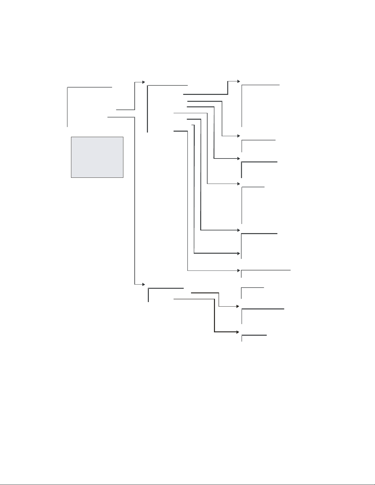
CDM-IP 300L IP-Centric Satellite Modem Rev. 1
CD/CDMIP300L.IOM
FUNCTION SELECT
CONFIGURATION
MONITOR
FAULTS/ALARMS
STORED/FAULTS
*
UTILITY
1
REMOTE AUPC
*
CONDITIONAL OR
OPTION DEPENDEN T
4
See 1/5
1
See 2/5
2
See 3/5
3
See 4/5
4
See 5/5
5
,
5
CDM-IP 300L Fro nt Panel Menu Tree
STO RED FAULTS (CON T.)
1
2
2
MODULATOR
DEMODULATOR
TX INTERFACE
RX INTERFACE
COMMON
OUTDOOR UNIT
UNAVAL SECONDS
CLEAR ? ?
REMOTE AUPC
CONFIGURATION
MONITOR
(3 Of 5)
DEMODULATOR
CARRIER DETECT
IF SYNTHESIZER
I CHANNEL
Q CHANNEL
BER THRESHOLD
MODULE
CONFIGURATION
LNB CURRENT
TX INTE RFACE
TX CLK PLL
CONFIGURATION
RX INTERFACE
RX DATA/AIS
BUFFER CLK PLL
CONFIGURATION
COMMON
BATTERY/CLOCK
-12 VOLT SUPPLY
+12 VOLT SUPPLY
+5 VOLT SUPPLY
SELF TEST
CONTROLLER
IP MODULE
OUTDOOR UNIT
CURRENT
VOLTAGE
TEMPERA TUR E
PLL LOC K
CHECKSU M
UNAVAL SECONDS 0
NO FAULT
CLEAR??
STORED FAULTS
YES
CONFIGURATION
AUPC ENABLE
B-BAND LOOPBACK
TX 2047
MONITOR
2047 ERRORS
Figure 12. Front Panel Modem Menu Tree (3 of 5)
56
Page 83

CDM-IP 300L IP-Centric Satellite Modem Rev. 1
CD/CDMIP300L.IOM
FUNC TION S ELECT
CONFIGURATION
MONITOR
FAULTS/ALARMS ,
STORED/FAULTS
*REMOTE AUPC
UTILITY
*
CONDITIONAL OR
OPTION DEPENDEN T
See 1/5
1
See 2/5
2
See 3/5
3
See 4/5
4
See 5/5
5
1
2
1
23
,
23
CDM-IP 300L Front Panel Menu Tree
UTILITY
MODULATOR
DEMODULATOR
INTERFACE
OUTDOOR U NIT
SYSTEM
MODEM TYPE
FACTORY SET-UP
5
(4 Of 5)
5
MODULATOR
ASSIGN TRANSMIT FILTERS
TX TERMINAL LO
MOD POWER OFFSET
ENCODER TYPE
SCRAMBLER
TX BPSK ORDERING
MOD SPECTRUM
TX-RS N/K DEEP
TX IESS-310 MODE
ODU ALARM - LOW
ODU ALARM - HIGH
RF MODE CONTROL
TX SYMBOL RATE
DEMODULATOR
ASSIGN RECEIVE FILTERS
RX TERMINAL LO
DECODER TYPE
DESCRAMBLER TYPE
RX BPSK ORDERING
DEMOD SPECTR UM
RX-RS N/K DEEP
RX IESS-3 10 MODE
LNB ALARM - LOW
LNB ALARM - HIGH
RX SYMBOL RATE
INTERFACE
TX OVERHEAD TYPE
RX OVERHEAD TYPE
OUTDOOR UNIT
ODU FSK A DDR ESS
ODU OUTPU T P OWER
ODU PWR L EVE LING
SYSTEM
TIME/DATE
REMOTE BAUD RATE
REMOTE ADDRESS
REMOTE TYPE
IP.NET PREFIX
OPERATION MODE
YEAR DISPLAY
TEST MODE STATUS
LAMP TEST ??
DISPLAY CONTRAST
M&C FIRMWARE
BOOT FIRMWARE
FPGA FIRMWARE
CIM FIRMWARE
IP DEMO MODE
EXT AGC: MAX PWR
EXT AGC: MIN PWR
MASTER RESET
Figure 13. Front Panel Modem Menu Tree (4 of 5)
57
Page 84

CDM-IP 300L IP-Centric Satellite Modem Rev. 1
CD/CDMIP300L.IOM
FUNC TION S ELECT
CONFIGURATION
MONITOR
FAULTS/ALARMS ,
STORED/FAULTS
*REMOTE AUPC
UTILITY
*
CONDITIONAL OR
OPTION DEPENDEN T
See 1/5
1
See 2/5
2
See 3/5
3
See 4/5
4
See 5/5
5
1
2
CDM-IP 300L Front Panel Menu Tree
(5 Of 5)
CDM-IP 300L Front Panel Menu Tree
(5 Of 5)
UTILITY
1
23
,
23
MODULATOR
DEMODULATOR
INTERFACE
OUTDOOR U NIT
SYSTEM
MODEM TYP E
FACTORY SET-UP
4
4
4
4
4
Figure 14. Front Panel Modem Menu Tree (5 of 5)
MODEM TYPE
MODEM TYP E
REV EMULATION
MODEM OPT ION S
CARD #1 TYPE
CARD #2 TYPE
CARD #3 TYPE
CARD #1 OPTIONS
CARD #2 OPTIONS
CARD #3 OPTIONS
LOCAL MOD EM AUP C
MODEM SER IAL #
CARD #1 SERIAL #
CARD #2 SERIAL #
CARD #3 SERIAL #
CONFIGURATION CODE MODEM
CONFIGURATION CODE - CARD #1
CONFIGURATION CODE - CARD #2
CONFIGURATION CODE - CARD #3
FACTORY SETUP
58
Page 85

CDM-IP 300L IP-Centric Satellite Modem Rev. 1
CD/CDMIP300L.IOM
4.2.1.1 OPENING SCREEN
DISPLAY SELECTIONS/DESCRIPTION
CDM300L CUSTOM
VER: 2.1.14
FUNCTION SELECT
CONFIGURATION
This screen is displayed whenever power is
first applied to the unit. Pressing any key will
take the user to the top-level selection screen.
CONFIGURATION, MONITOR,
FAULTS/ALARMS, STORED/FAULTS,
REMOTE AUPC*, UTILITY.
* Conditional or option dependent.
4.2.1.1.1 Function Select – Configuration
The user is presented with the following choices:
DISPLAY SELECTIONS/DESCRIPTION
CONFIGURATION
MODULATOR
MODULATOR
DEMODULATOR
INTERFACE
*LOCAL AUPC
SAVE
RECALL
* Conditional or option dependent.
4.2.1.1.1.1 Configuration – Modulator
DISPLAY SELECTIONS/DESCRIPTION
CONFIGURATION
MODULATOR
TX-V QPSK 1/2
64.000 Kbps
TX-IF FREQUENCY
70.0000 MHz
or
Filters: A, B, C, D, or V.
See filter assignments for valid rates.
50 to 180 MHz (in 1 Hz steps).
* non TX/RF L-Band modem only.
59
Page 86

CDM-IP 300L IP-Centric Satellite Modem Rev. 1
CD/CDMIP300L.IOM
DISPLAY SELECTIONS/DESCRIPTION
TX-IF FREQUENCY
1200.0000 MHz
950 to 1750 MHz (in 100 Hz steps).
* non TX/RF L-Band modem (non-terminal
frequency mode) only.
or
TX-IF FREQUENCY
5845.0000 MHz
TX-IF OUTPUT
OFF
TX POWER LEVEL
+5.0 dBm
TX POWER LEVEL
-10.0 dBm
SCRAMBLER
ON
DIFF. ENCODER
ON
CARRIER MODE
NORMAL-MODULATED
MODEM REFERENCE
INTERNAL
Range dependent on LO and Mix (in 1 MHz
steps).
* non TX/RF L-Band modem (terminal
frequency mode) only.
ON, OFF.
-5.0 to –30.0 dBm (normal range)
+5.0 to –20 dBm (high power option)
*non TX/RF L-Band modem only
0.0 to –40.0 dBm
*TX/RF L-Band modem only
ON, OFF
ON, OFF
NORMAL-MODULATED
CENTER-CW
OFFSET-CW
DUAL-CW
INTERNAL
EXT1MHz
EXT5MHz
EXT10 MHz
EXT 20 MHz
OUTPUT 10MHZ – (High Stability option only)
60
Page 87

CDM-IP 300L IP-Centric Satellite Modem Rev. 1
CD/CDMIP300L.IOM
DISPLAY SELECTIONS/DESCRIPTION
FSK OUTPUT
ON
ODU POWER SUPPLY
OFF
ODU OUTPUT DELAY
00.00 MIN.SEC
ODU 10 MHz REF
OFF
RS ENCODER
OFF
ON, OFF
ON, OFF
* TX/RF L-Band modem only.
ON, OFF
*TX/RF L-Band modem only.
ON, OFF
*Reed-Solomon option only.
4.2.1.1.1.2 Configuration – Demodulator
DISPLAY SELECTIONS/DESCRIPTION
CONFIGURATION
DEMODULATOR
RX-V OQPSK 1/2
768.000 Kbps
RX-IF FREQUENCY
1200.0000 MHz
or
61
Filters: A, B, C, D, or V.
See filter assignments for valid rates.
950 to 1750 MHz (in 100Hz steps).
Page 88

CDM-IP 300L IP-Centric Satellite Modem Rev. 1
CD/CDMIP300L.IOM
DISPLAY SELECTIONS/DESCRIPTION
RX-IF FREQUENCY
1200.0000 MHz
950 to 1750 MHz (in 100Hz steps).
*Non-terminal frequency mode only.
DESCRAMBLER
ON, OFF
ON
DIFF. DECODER
ON, OFF
ON
RF LOOP BACK
ON
ON, OFF
* TX/RF L-Band modem only.
IF LOOP BACK
ON
ON, OFF
* TX/RF L-Band modem only.
BER THRESHOLD
NONE or 1.0 E-x (where x = 3 to 8)
NONE
SWEEP CENTER
-75,000 to +75,000 Hz
+ 0 Hz
SWEEP RANGE
0 to 150,000 Hz
60000 Hz
REACQUISITION
0 to 999 Seconds
0 SECONDS
62
Page 89

CDM-IP 300L IP-Centric Satellite Modem Rev. 1
CD/CDMIP300L.IOM
DISPLAY SELECTIONS/DESCRIPTION
LNB POWER
OFF
LNB VOLTAGE
13 Vdc
LNB 10 MHz REF
OFF
RS DECODER
OFF
ON, OFF
13, 18, or 24 Vdc
ON, OFF
ON
OFF
CORRECTION_OFF
*Reed-Solomon option only.
4.2.1.1.1.3 Configuration - Interface
DISPLAY SELECTIONS/DESCRIPTION
CONFIGURATION
INTERFACE
None of the Configuration Interface
functions apply to the CDM-IP 300L
4.2.1.1.1.4 Configuration - Local AUPC (Optional)
DISPLAY SELECTIONS/DESCRIPTION
LOCAL AUPC
ON
OFF
63
Page 90

CDM-IP 300L IP-Centric Satellite Modem Rev. 1
CD/CDMIP300L.IOM
DISPLAY SELECTIONS/DESCRIPTION
AUPC ENABLE
Programs the nominal power value of the
AUPC. The nominal power value can
range from -5 to -30 dBm, in 0.5 dBm
steps.
Upon entry, the current nominal power
value is displayed. Press [↑] or [↓] to
increment or decrement the digit at the
flashing cursor. Press [ENTER] to
execute the change.
NOMINAL POWER
Programs the nominal power value of the
AUPC. The nominal power value can
range from -5 to -30 dBm, in 0.5 dBm
steps.
Upon entry, the current nominal power
value is displayed. Press [↑] or [↓] to
increment or decrement the digit at the
flashing cursor. Press [ENTER] to
execute the change.
MINIMUM POWER
Programs the minimum power level of the
AUPC. The minimum power level can
range from -5 to -30 dBm, in 0.5 dBm
steps.
Upon entry, the current minimum power
level is displayed. Press [↑] or [↓] to
increment or decrement the digit at the
flashing cursor. Press [ENTER] to
MAXIMUM POWER
execute the change.
Programs the maximum power level of
the AUPC. The maximum power level
can range from -5 to -30 dBm, in 0.5 dBm
steps.
Upon entry, the current maximum power
level is displayed. Press [↑] or [↓] to
increment or decrement the digit at the
flashing cursor. Press [ENTER] to
execute the change.
TARGET NOISE
Programs the Eb/No target set point. The
Eb/No target set point ranges from 3.2 to
16.0 dB, in 0.1 dB steps.
Upon entry, the current Eb/No target set
point is displayed. Press [↑] or [↓] to
increment or decrement the digit at the
flashing cursor. Press [ENTER] to
execute the change.
64
Page 91

CDM-IP 300L IP-Centric Satellite Modem Rev. 1
CD/CDMIP300L.IOM
DISPLAY SELECTIONS/DESCRIPTION
TRACKING RATE
Programs the maximum tracking rate of
the AUPC.
Maximum tracking rate can range from
0.5 to 6.0 dBm/minute, in 0.5 dBm/minute
steps.
Upon entry, the current maximum
tracking rate is displayed. Press [↑] or [↓]
to increment or decrement the digit at the
flashing cursor. Press [ENTER] to
execute the change.
LOCAL CL ACTION
Programs the local carrier loss for HOLD,
NOMINAL, or MAXIMUM.
Upon entry, the status of the local carrier
loss is displayed. Press [↑] or [↓] to make
the selection. Press [ENTER] to execute
the change.
REMOTE CL ACTION
Programs the remote carrier loss for HOLD,
NOMINAL, or MAXIMUM.
Upon entry, the status of the remote carrier
loss is displayed. Press [↑] or [↓] to make the
selection. Press [ENTER] to execute the
change.
4.2.1.1.1.5 Configuration - Save
DISPLAY SELECTIONS/DESCRIPTION
CONFIGURATION
SAVE
CONFIGURATION #1
SAVE
The Configuration Save menu allows
programming of configuration parameters into
memory on the M&C. There are five memory
locations that may be used to store specific
configuration setups that are used frequently.
After changing the configuration parameters
to the desired settings, enter the
Configuration Save menu and select memory
location 1 through 5. Press [ENTER] to
execute the save.
65
Page 92

CDM-IP 300L IP-Centric Satellite Modem Rev. 1
CD/CDMIP300L.IOM
4.2.1.1.1.6 Configuration - Recall
DISPLAY SELECTIONS/DESCRIPTION
CONFIGURATION
RECALL
CONFIGURATION #1
RECALL
The Configuration Recall menu allows the
user to recall a previously saved configuration
setup. Upon entry, select memory location 1
through 5 by pressing [↑] or [↓]. Press
[ENTER] to execute the recall.
4.2.1.1.2 Function Select – Monitor
DISPLAY SELECTIONS/DESCRIPTION
FUNCTION SELECT
MONITOR
RAW BER
CORRECTED BER
RECEIVE SIGNAL
SWEEP FREQ
BUFFER FILL
TX-RS N/K DEPTH
RX-RS N/K DEPTH
LNB CURRENT
ODU CURRENT
4.2.1.1.2.1 Monitor – Raw BER
DISPLAY SELECTIONS/DESCRIPTION
RAW BER
No Data
4.2.1.1.2.2 Monitor – Corrected BER
DISPLAY SELECTIONS/DESCRIPTION
CORRECTED BER
No Data
Displays the current BER or “No Data” (if
carrier is not locked).
Range: < m.m E-e to > m.m E-e.
Note: Low limit is based on performance.
High limit is based on data/code rate.
Displays the current corrected BER or “No
Data” (if carrier is not locked).
Range: 1.0 E-3 to 1.0 E-12.
Note: Low limit is based on performance.
High limit is 1.0 E-12.
66
Page 93

CDM-IP 300L IP-Centric Satellite Modem Rev. 1
CD/CDMIP300L.IOM
4.2.1.1.2.3 Monitor – Eb/No
DISPLAY SELECTIONS/DESCRIPTION
EB/NO
No Data
Displays the current Eb/No or “No Data” (if
carrier is not locked).
Range: 2.0 to 16.0 dB.
Note: Low limit is based on the data rate.
High limit is 16.0 dB.
4.2.1.1.2.4 Monitor – Receive Signal
DISPLAY SELECTIONS/DESCRIPTION
RECEIVE SIGNAL
<91.9dBm
Displays the current receive signal level.
Range: -25.0 to –91.9 dBm.
4.2.1.1.2.5 Monitor – Sweep Frequency
DISPLAY SELECTIONS/DESCRIPTION
SWEEP FREQUENCY
No Data
4.2.1.1.2.6 Monitor – Buffer Fill
DISPLAY SELECTIONS/DESCRIPTION
BUFFER FILL
50%
4.2.1.1.2.7 Monitor – LNB Current
DISPLAY SELECTIONS/DESCRIPTION
LNB CURRENT
Displays the current offset frequency or “No
Data” if carrier is not locked
Range: -35,000 to +35,000 Hz
Displays the current plesiochronous buffer fill
status percent.
Range: 1 to 99%.
Monitors the LNB current or LNB POWER OFF.
Current displayed is 0 to 500 mA in 1 mA
increments
67
Page 94

CDM-IP 300L IP-Centric Satellite Modem Rev. 1
CD/CDMIP300L.IOM
4.2.1.1.2.8 Monitor – Loop Timing
DISPLAY SELECTIONS/DESCRIPTION
ODU CURRENT
Monitors the ODU current or ODU POWER
OFF. Current displayed is 0 to 4000 mA in 1
mA increments
4.2.1.1.3 Function Select – Faults/Alarms
DISPLAY SELECTIONS/DESCRIPTION
CONFIGURATION
FAULTS/ALARMS
MODULATOR
DEMODULATOR
TX INTERFACE
RX INTERFACE
COMMON
OUTDOOR UNIT
UNAVALSECONDS
CLEAR??
4.2.1.1.3.1 Faults/Alarms – Modulator
DISPLAY SELECTIONS/DESCRIPTION
MODULATOR
▓--------
IF SYNTHESIZER
▓--------
DATA CLOCK SYN
-▓-------
I CHANNEL
--▓------
NOTE:
“-” indicates status of parameter is OK.
“+” indicates a fault.
Reverse contrast “+” indicates an alarm.
Modulator IF synthesizer fault
Transmit clock synthesizer fault. Indicates the
internal Voltage Controlled Oscillator (VCO)
has not locked to the incoming data clock
I channel data activity fault
68
Page 95

CDM-IP 300L IP-Centric Satellite Modem Rev. 1
CD/CDMIP300L.IOM
DISPLAY SELECTIONS/DESCRIPTION
Q CHANNEL
---▓-----
AGC LEVEL
----▓----
MODEM REF ACT
-----▓---
MODEM REF PLL
------▓--
Q channel data activity fault
TX IF AGC level fault
MODEM REF activity alarm
MODEM REF PLL not locked
MODULE
-------▓-
CONFIGURATION
--------▓
Modulator module fault
Modulator configuration fault
4.2.1.1.3.2 Faults/Alarms – Demodulator
DISPLAY SELECTIONS/DESCRIPTION
DEMODULATOR
▓--------
CARRIER DETECT
▓--------
IF SYNTHESIZER
-▓-------
69
Note: “-” indicates status of parameter is OK.
“+” indicates a fault.
Reverse contrast “+” indicates an
alarm.
Carrier detect fault. Indicates the decoder is
not locked
Demodulator IF synthesizer fault. Indicates
the IF synthesizer is not locked
Page 96

CDM-IP 300L IP-Centric Satellite Modem Rev. 1
CD/CDMIP300L.IOM
I CHANNEL
--▓------
Q CHANNEL
---▓-----
BER THRESHOLD
----▓----
MODULE
-----▓---
CONFIGURATION
------▓--
LNB
-------▓-
I channel activity fault. Indicates a loss of
activity in the I channel of the quadrature
demodulator
Q channel activity fault. Indicates a loss of
activity in the Q channel of the quadrature
demodulator
Secondary alarm result of the BER threshold
set in the DEMOD Configuration menu
Demodulator/decoder module fault
Demodulator/decoder configuration fault
LNB configuration fault
4.2.1.1.3.3 Faults/Alarms – Tx Interface
DISPLAY SELECTIONS/DESCRIPTION
TX INTERFACE
-------
TX CLK PLL
--▓----
CONFIGURATION
------▓
70
Note: “-” indicates status of parameter is OK.
“+” indicates a fault.
Reverse contrast “+” indicates an
alarm.
Transmitter phase-locked loop fault. Indicates
the transmitter Phase-Locked Loop (PLL) is
not locked
TX interface configuration fault.
Indicates the TX interface cannot execute a
programmed configuration parameter
Page 97

CDM-IP 300L IP-Centric Satellite Modem Rev. 1
CD/CDMIP300L.IOM
4.2.1.1.3.4 Faults/Alarms – Rx Interface
DISPLAY SELECTIONS/DESCRIPTION
RX INTERFACE
--------------
RX DATA/AIS
--▓-----------
BUFFER CLK PLL
-----▓--------
CONFIGURATION
-------------▓
NOTE:
“-” indicates status of parameter is OK.
“+” indicates a fault.
Reverse contrast “+” indicates an alarm.
Data or AIS. When data fault is selected in
the Configuration Interface menu (4.2.1.1.1),
the fault indicates a data stable condition.
This indicates the data coming from the
satellite is all 1s or 0s (i.e., data is not
transitioning). When AIS is selected, the
Alarm indicates the data is all 1s from the
satellite. When None is selected in the
Configuration Interface menu, the RX
DATA/AIS Fault/Alarm is not activated.
Note: AIS is an alarm, not a switching fault.
Buffer clock phase-locked loop fault. Indicates
the buffer clock PLL is not locked
Configuration alarm
71
Page 98

CDM-IP 300L IP-Centric Satellite Modem Rev. 1
CD/CDMIP300L.IOM
4.2.1.1.3.5 Faults/Alarms – Common
DISPLAY SELECTIONS/DESCRIPTION
COMMON
▓------
BATTERY CLOCK
▓------
-12 VOLT SUPPLY
-▓-----
+12 VOLT SUPPLY
--▓----
+5 VOLT SUPPLY
---▓---
SELF TEST
----▓--
CONTROLLER
-----▓-
IP MODULE
------▓
Note: “-” indicates status of parameter is OK.
“+” indicates a fault.
Reverse contrast “+” indicates an
alarm
Battery or clock fault
-12 Vdc power supply fault
+12 Vdc power supply fault
+5 Vdc power supply fault
Built in self test fault
Controller fault. Typically indicates the
controller has gone through a power on/off
cycle
IP module fault. Typically indicates that the IP
module will not program
72
Page 99

CDM-IP 300L IP-Centric Satellite Modem Rev. 1
CD/CDMIP300L.IOM
4.2.1.1.3.6 Faults/Alarms – Outdoor Unit
DISPLAY SELECTIONS/DESCRIPTION
OUTDOOR UNIT
-----
CURRENT
▓----
VOLTAGE
-▓---
TEMPERATURE
-----
PLL LOCK
-----
CHECKSUM
-----
Note: “-” indicates status of parameter is OK.
“+” indicates a fault.
Reverse contrast “+” indicates an
alarm
Current fault
Voltage fault
Temperature fault
PLL Lock fault
Checksum fault
73
Page 100

CDM-IP 300L IP-Centric Satellite Modem Rev. 1
CD/CDMIP300L.IOM
4.2.1.1.4 Function Select – Stored/Faults
DISPLAY SELECTIONS/DESCRIPTION
FUNCTION SELECT
STORED FLTS/ALMS
MODULATOR
DEMODULATOR
TX INTERFACE
RX INTERFACE
COMMON
OUTDOOR UNIT
UNAVAL SECONDS
CLEAR ??
4.2.1.1.4.1 Stored/Faults – Modulator
DISPLAY SELECTIONS/DESCRIPTION
MODULATOR 0
11/01/02
IF SYNTHESIZER
▓--------
DATA CLOCK SYN
-▓-------
I CHANNEL
--▓------
Q CHANNEL
----▓----
AGC LEVEL
-----▓---
Note:
“-” indicates status of parameter is OK.
“+” indicates a fault.
Reverse contrast “+” indicates an alarm.
Modulator IF synthesizer fault
Transmit clock synthesizer fault. Indicates the
internal Voltage Controlled Oscillator (VCO)
has not locked to the incoming data clock
I channel data activity fault
Q channel data activity fault
TX IF AGC level fault
74
 Loading...