

Page 1

M
-
7
0
CD
Advanced Satellite Modem
Installation and Operation Manual
4
IMPORTANT NOTE: The information contained in this document supersedes all previously published
information regarding this product. Product specifications are subject to change without prior notice.
Part Number
MN-CDM740 Revision 0
Page 2

Page 3
Errata A
Comtech EF Data Documentation Update
Errata Page 1 of 4
Subject:
Date:
Original Manual Part
Number/Rev:
Errata Number/
Agile Document ID:
Agile CO Number:
Comments:
Affected content:
Update CDM-740 Firmware Upgrade Procedure, Front Panel
Operation, and Web Server login parameters
January 19, 2010
MN-CDM740 Rev 0
ER-MNCDM740.EA0
CO 10672
Affected manual / page content will be updated, as indicated below
and on the pages that follow, upon next formal manual revision.
• Chapter 4. FLASH UPGRADING,
Update Sect. 4.2 Ethernet Upload Procedure
• Chapter 5. FRONT PANEL OPERATION,
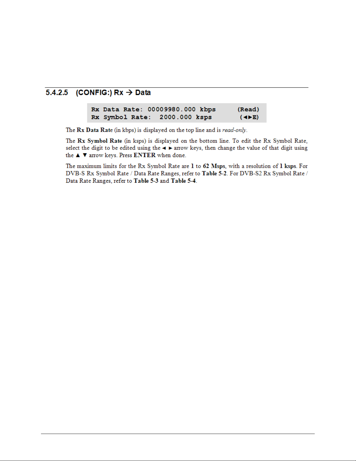
Replace Sect. 5.4.2.5 (CONFIG:) Rx Æ Data
• Chapter 6. ETHERNET MANAGEMENT,
Replace Sect. 6.5.3. User Login
AGILE DOC ID ER-MNCDM740.EA0 THIS DOCUMENT IS NOT SUBJECT TO REVISION/UPDATE! AGILE CO10672
Page 4

I. Chapter 4. FLASH UPGRADING
Update Sect. 4.2 Ethernet Upload Procedure (pages 4-2, 4-3)
Instructions: Steps 3, 4, and 9 in Sect. 4.2 are replaced in their entirety as follows:
3. Download the correct firmware file to this temporary folder. As shown in Figure 4-1:
Errata Page 2 of 4
o
o
1. Go online to: www.comtechefdata.com
;
2. Click on: Support tab;
3. Click on: Software Downloads drop-down or hyperlink from Support page;
4. Click on: Download Flash and Software Update Files icon;
5. Click on: (Select a Product Line) Satellite Modems hyperlink;
6. Select the CDM-740 product hyperlink;
7. Select the appropriate firmware hyperlink.
About Firmware Numbers, File Versions, and Formats: The flashable files on the download
server are organized by product prefix; firmware number (verify that the correct firmware
number is known – see Step 1); revision letter, if applicable; and release version.
The downloadable for the CDM-740 base modem bulk firmware is named F0000279x_V###,
where “x” denotes the revision letter, and “###” the firmwar e version. The do wnl oada ble fil es
are stored in two formats: *.exe (self-extracting) and *.zip (compressed). Some firewalls will
not allow the downloading of *.exe files; in this case, download the *.zip file instead.
The current version firmware release is provided. If applicable, one version prior to the
current release is also available. Be sure to identify and download the desired version.
For additional help with "zipped" file types, refer to PKZIP for Windows, WinZip, or
ZipCentral help files. PKZIP for DOS is not
supported due to file naming conventions.
4. Extract the files into the temporary folder on the PC. At least two files should be
extracted (where the “x” in each filename represents the firmware revision letter):
• FW-0000279x.pkg, the bulk image file;
• ReleaseNotes_FW-0000279x.pdf, the firmware release notes document.
o
o
o
o
9. Transfer the files: Type "put FW-0000279*.pkg" to begin the file transfers. It will take
a few seconds to transfer the file.
AGILE DOC ID ER-MNCDM740.EA0 THIS DOCUMENT IS NOT SUBJECT TO REVISION/UPDATE! AGILE CO10672
Page 5
II. Chapter 5. FRONT PANEL OPERATION
Replace Sect. 5.4.2.5 (CONFIG:) Rx Æ Data (page 5-10)
Instructions: Sect. 5.4.2.5 is replaced in its entirety as follows:
Errata Page 3 of 4
AGILE DOC ID ER-MNCDM740.EA0 THIS DOCUMENT IS NOT SUBJECT TO REVISION/UPDATE! AGILE CO10672
Page 6

III. Chapter 6. ETHERNET MANAGEMENT
Replace Sect. 6.5.3 User Login (page 6-5)
Instructions: Sect. 6.5.3 is replaced in its entirety as follows:
Errata Page 4 of 4
AGILE DOC ID ER-MNCDM740.EA0 THIS DOCUMENT IS NOT SUBJECT TO REVISION/UPDATE! AGILE CO10672
Page 7

CDM-740
Advanced Satellite Modem
Installation and Operation Manual
Part Number MN-CDM740
Revision 0
December 17, 2009
Copyright © 2009 Comtech EF Data. All rights reserved. Printed in the USA.
Comtech EF Data, 2114 West 7th Street, Tempe, Arizona 85281 USA, 480.333.2200, FAX: 480.333.2161
Page 8

This page is intentionally blank.
Page 9

Table of Contents
TABLE OF CONTENTS .............................................................................................................. III
TABLES ...................................................................................................................................... IX
FIGURES .................................................................................................................................... IX
PREFACE ................................................................................................................................... XI
About this Manual
Reporting Comments or Suggestions Concerning this Manual ............................................................... xi
Conventions and References ..................................................................................................................... xi
Metric Conversion ................................................................................................................................... xi
Recommended Standard Designations ..................................................................................................... xi
Trademarks .............................................................................................................................................. xi
Cautions and Warnings ............................................................................................................................ xii
Electrical Safety and Compliance ............................................................................................................ xii
Fuses ....................................................................................................................................................... xii
Low Voltage Directive (LVD) ............................................................................................................... xiii
Installation.............................................................................................................................................. xiii
Environmental .......................................................................................................................................... xiii
Telecommunications Terminal Equipment Directive ........................................................................... xiv
CE Mark ................................................................................................................................................... xiv
RoHS Compliance .................................................................................................................................... xiv
EMC (Electromagnetic Compatibility) Compliance ............................................................................. xiv
..................................................................................................................................... xi
Warranty Policy ........................................................................................................................................ xv
Limitations of Warranty .......................................................................................................................... xv
Exclusive Remedies ............................................................................................................................... xvi
Customer Support ................................................................................................................................... xvii
Online Customer Support ..................................................................................................................... xvii
CHAPTER 1. INTRODUCTION ............................................................................................. 1–1
1.1 Overview ...................................................................................................................................... 1–1
iii
Page 10

CDM-740 Advanced Satellite Modem Revision 0
Table of Contents MN-CDM740
1.2 Functional Description ............................................................................................................... 1–2
1.3 Features ........................................................................................................................................ 1–4
1.3.1 Physical Description ............................................................................................................. 1–4
1.3.2 Compatibility ........................................................................................................................ 1–4
1.3.3 Major Assemblies ................................................................................................................. 1–4
1.3.4 Dimensional Envelope .......................................................................................................... 1–5
1.3.5 Physical Features .................................................................................................................. 1–6
1.3.5.1 Front Panel ........................................................................................................................ 1–6
1.3.6 Rear Panel ............................................................................................................................. 1–7
1.3.7 Data Interfaces ...................................................................................................................... 1–7
1.3.11 Supporting Hardware and Software ...................................................................................... 1–9
1.4 New in this Release ...................................................................................................................... 1–9
1.5 Summary of Specifications ....................................................................................................... 1–10
1.5.1 Transmit / Modulator .......................................................................................................... 1–10
1.5.2 Receive / Demodulator........................................................................................................ 1–11
1.5.3 Data Interfaces .................................................................................................................... 1–12
1.5.4 Data Rate Ranges ................................................................................................................ 1–12
1.5.5 Miscellaneous ..................................................................................................................... 1–13
1.5.6 Approvals ............................................................................................................................ 1–13
CHAPTER 2. INSTALLATION .............................................................................................. 2–1
2.1 Unpacking and Inspectio
n .......................................................................................................... 2–1
2.2 Mounting ...................................................................................................................................... 2–2
2.2.1 Optional Rear-Mounting Support Bracket Installation ......................................................... 2–2
CHAPTER 3. REAR PANEL CONNECTOR PINOUTS ........................................................ 3–1
3.1 Connector Overview ................................................................................................................... 3–1
3.2 IF Connections ............................................................................................................................ 3–3
3.2.1 Rx IF Connectors .................................................................................................................. 3–3
3.2.2 Tx IF Connectors .................................................................................................................. 3–3
3.3 Terrestrial Data Connections ..................................................................................................... 3–3
3.3.1 GE-1 and GE-2 Ethernet Connectors, RJ-45 ........................................................................ 3–3
3.3.2 FE (Fast Ethernet) Connector, RJ-45 .................................................................................... 3–3
3.3.3 ASI IN/OUT 1 & 2 Connectors, BNC (UNUSED) .............................................................. 3–4
3.4 Utility Connections ...................................................................................................................... 3–4
3.4.1 TERM Connector, RJ-12 ...................................................................................................... 3–4
3.4.2 REDUNDANT Connector, DB-9F ....................................................................................... 3–4
3.4.3 Remote Control Interface Connector, DB-9M ...................................................................... 3–5
3.4.4 EXT/INT REF Connector, BNC ........................................................................................... 3–5
iv
Page 11

CDM-740 Advanced Satellite Modem Revision 0
Table of Contents MN-CDM740
3.5 Power / Ground Connections ..................................................................................................... 3–6
3.5.1 Alternating Current Power Connector .................................................................................. 3–6
3.5.2 Direct Current (DC) Power Connector (Optional) ................................................................ 3–6
3.5.3 Chassis Ground Connector .................................................................................................... 3–6
CHAPTER 4. FLASH UPGRADING ...................................................................................... 4–1
4.1 Flash Updating via Internet ....................................................................................................... 4–1
4.2 Ethernet FTP Upload Procedure ............................................................................................... 4–2
CHAPTER 5. FRONT PANEL OPERATION ......................................................................... 5–1
5.1 Description ................................................................................................................................... 5–1
5.1.1 Front Panel LED Indicators .................................................................................................. 5–2
5.1.2 Front Panel Keypad ............................................................................................................... 5–2
5.1.3 Front Panel Vacuum Fluorescent Display (VFD) ................................................................. 5–3
5.2 Front Panel Menu ....................................................................................................................... 5–3
5.2.1 Opening Screen ..................................................................................................................... 5–3
5.2.2 CDM-740 Front Panel Menu Matrix .................................................................................... 5–4
5.3 SELECT: (Main) Menu .............................................................................................................. 5–5
5.4 SELECT: Configuration ............................................................................................................ 5–6
5.4.1 CONFIG: Tx ......................................................................................................................... 5–6
5.4.1.1 (CONFIG:) Tx Æ IF ......................................................................................................... 5–6
5.4.1.2 (CONFIG:) Tx Æ Freq (Frequency) ................................................................................. 5–7
5.4.1.3 (CONFIG:) Tx Æ Power .................................................................................................. 5–7
5.4.1
.4 (CONFIG:) Tx Æ FEC ..................................................................................................... 5–7
5.4.1.5 (CONFIG:) Tx Æ Mod (Modulation) ............................................................................... 5–7
5.4.1.6 (CONFIG:) Tx Æ Data ..................................................................................................... 5–8
5.4.1.7 (CONFIG:) Tx Æ Scrambler ............................................................................................ 5–8
5.4.2 CONFIG: Rx ......................................................................................................................... 5–9
5.4.2.1 (CONFIG:) Rx Æ IF ......................................................................................................... 5–9
5.4.2.2 (CONFIG:) Rx ÆFreq (Frequency) .................................................................................. 5–9
5.4.2.3 (CONFIG:) Rx Æ FEC ..................................................................................................... 5–9
5.4.2.4 (CONFIG:) Rx Æ Demod (Demodulation) .................................................................... 5–10
5.4.2.5 (CONFIG:) Rx Æ Data ................................................................................................... 5–10
5.4.2.6 (CONFIG:) Rx Æ Descram(bler) (DVB-S2 only) .......................................................... 5–11
5.4.2.7 (CONFIG:) Rx Æ Pilot (DVB-S2 only) ......................................................................... 5–11
5.4.3 CONFIG: Clocks ................................................................................................................ 5–14
5.4.3.1 (CONFIG:) Clocks Æ Ext-Ref ....................................................................................... 5–14
5.4.3.2 (CONFIG:) Clocks Æ Int-Ref-Adj ................................................................................. 5–14
5.4.4 CONFIG: Remote ............................................................................................................... 5–15
5.4.4.1 (CONFIG:) Remote Æ Serial ......................................................................................... 5–15
5.4.5 CONFIG: IP
........................................................................................................................ 5–15
5.4.5.1 (CONFIG:) IP Æ (GE1 / GE2 / MGMT) ........................................................................ 5–16
5.4.5.2 (CONFIG:) IP Æ (SNMP) Read-Cmty ........................................................................... 5–17
v
Page 12

CDM-740 Advanced Satellite Modem Revision 0
Table of Contents MN-CDM740
5.4.5.3 (CONFIG:) IP Æ (SNMP) Write-Cmty .......................................................................... 5–18
5.4.5.4 (CONFIG:) IP Æ SNMP Æ Trap ................................................................................... 5–18
5.4.6 CONFIG: Misc .................................................................................................................... 5–18
5.5 SELECT: Test ........................................................................................................................... 5–19
5.5.1 TEST: Mode ........................................................................................................................ 5–19
5.5.2 TEST: BERT ....................................................................................................................... 5–19
5.5.2.1 TEST: Pattern .................................................................................................................. 5–19
5.6 SELECT: Monitor .................................................................................................................... 5–20
5.6.1 Monitor: Live-Alarms ......................................................................................................... 5–20
5.6.2 Monitor: Stored-Events ....................................................................................................... 5–21
5.6.2.1 (Monitor:) Stored-Events Æ Clear-All ........................................................................... 5–21
5.6.2.2 (Monitor:) Stored-Events Æ View .................................................................................. 5–21
5.6.3 Monitor: Rx-Params ............................................................................................................ 5–21
5.6.4 Monitor: IP-Stats ................................................................................................................. 5–22
5.7 SELECT: Store/Ld ................................................................................................................... 5–23
5.8 SELECT: Utility ........................................................................................................................ 5–24
5.8.1 Utilities: Set-RTC ............................................................................................................... 5–24
5.8.2 Utilities: Display-Brightness ............................................................................................... 5–24
5.8.3 Utilities: 1:1 ........................................................................................................................ 5–24
5.8.4 Utilities: 1:N (UNUSE
D) .................................................................................................... 5–25
5.8.5 Utilities: Circuit-ID ............................................................................................................. 5–25
5.8.6 Utilities: Firmware .............................................................................................................. 5–26
5.8.6.1 (Utilities): Firmware Æ Info ........................................................................................... 5–26
5.8.6.2 (Utilities): Firmware Æ Select ........................................................................................ 5–26
5.9 SELECT: ODU .......................................................................................................................... 5–27
5.9.1 ODU: (BUC:) BUC_LO ..................................................................................................... 5–27
5.9.1.1 ODU: (BUC:) Power ....................................................................................................... 5–28
5.9.1.2 ODU: (BUC:) 10M-Ref .................................................................................................. 5–28
5.9.1.3 ODU: (BUC) Alarm ........................................................................................................ 5–28
5.9.1.4 ODU: (BUC) Monitor ..................................................................................................... 5–28
5.9.1.5 ODU: (LNB) LNB_LO ................................................................................................... 5–28
5.9.1.6 ODU: (LNB) 22K-Tone .................................................................................................. 5–29
5.9.1.7 ODU: (LNB) Polarity ...................................................................................................... 5–29
5.10 SELECT: FAST ........................................................................................................................ 5–30
5.10.1 FAST: Options .................................................................................................................... 5–30
5.10.2 FAST: Configure ................................................................................................................ 5–30
5.10.2.1 FAST: Configure Æ Word# ........................................................................................ 5–31
5.10.3 FAST: Demo-Mode ............................................................................................................ 5–31
CHAPTER 6. ETHERNET MANAGEMENT .......................................................................... 6–1
6.1 Introduction ................................................................................................................................. 6–1
6.2 Ethernet Ma
vi
nagement Interface Protocols ............................................................................... 6–1
Page 13

CDM-740 Advanced Satellite Modem Revision 0
Table of Contents MN-CDM740
6.3 SNMP Interface ........................................................................................................................... 6–1
6.3.1 Management Information Base (MIB) Files ......................................................................... 6–2
6.3.2 SNMP Community Strings ................................................................................................... 6–2
6.4 Telnet Interface ........................................................................................................................... 6–3
6.5 Web Server (HTTP) Interface ................................................................................................... 6–4
6.5.1 Web Server Introduction ....................................................................................................... 6–4
6.5.2 Web Server Menu Tree ......................................................................................................... 6–4
6.5.3 User Login ............................................................................................................................ 6–5
6.5.4 Web Server Page Descriptions .............................................................................................. 6–6
6.5.4.1 Home (Splash) Page .......................................................................................................... 6–6
6.5.4.2 Management Pages ........................................................................................................... 6–7
6.5.4.2.1 Management | Main Page ............................................................................................ 6–7
6.5.4.2.2 Management | SNMP Page ......................................................................................... 6–9
6.5.4.2.3 Management | FAST Page ........................................................................................ 6–10
6.5.4.2.4 Management | Firmware Page ................................................................................... 6–11
6.5.4.2.5 Management | Auto Logout Page .............................................................................. 6–12
6.5.4.3 Network Pages ................................................................................................................ 6–13
6.5.4.3.1 Network | FE Mgt Page ............................................................................................. 6–13
6.5.4.3.2 Network | GE-1 and GE-2 Pages .............................................................................. 6–15
6.5.4.4 DEMOD (Demodulator) | Tuner-1 Page ......................................................................... 6–16
6.5.4.5 DECAP (Decapsulator) | Tuner-1 Page .......................................................................... 6–18
6.5.4.6 MOD (Modulator) Page .................................................................................................. 6–20
6.5.4.7 Statistics Pages ................................................................................................................ 6–23
6.5.4
.7.1 Statistics | Summary Page ......................................................................................... 6–23
6.5.4.7.2 Statistics | Tuner-1 Page ............................................................................................ 6–24
6.5.4.7.3 Statistics | GE-1 and GE-2 Pages .............................................................................. 6–25
6.5.4.7.4 Statistics | Modulator Page ........................................................................................ 6–26
6.5.4.8 Monitor Page ................................................................................................................... 6–27
6.5.4.9 Utility Page ..................................................................................................................... 6–28
APPENDIX A. REMOTE CONTROL .................................................................................... A–1
A.1 Overview ..................................................................................................................................... A–1
A.2 EIA-232 ....................................................................................................................................... A–1
A.3 Basic Protocol ............................................................................................................................. A–1
A.4 Packet Structure ......................................................................................................................... A–2
A.4.1 Start of Packet ...................................................................................................................... A–2
A.4.2 Target Address ..................................................................................................................... A–2
A.4.3 Address Delimiter ................................................................................................................ A–2
A.4.4 Instruction Code ................................................................................................................... A–2
A.4.5 Instruction Code Qualifier ................................................................................................... A–3
A.4.6 Optional Message Arguments .............................................................................................. A–4
A.4.7 End of Packet ....................................................................................................................... A–4
A.5 Remote Commands and Queries .............................................................................................. A–5
vii
Page 14

CDM-740 Advanced Satellite Modem Revision 0
Table of Contents MN-CDM740
A.5.1 Tx Parameters ...................................................................................................................... A–6
A.5.2 Rx Parameters ...................................................................................................................... A–9
A.5.3 Unit Parameters .................................................................................................................. A–12
A.5.4 Bulk Configuration Strings ................................................................................................ A–19
A.5.5 Modem Information ........................................................................................................... A–19
A.5.6 Modem Performance Information ...................................................................................... A–21
A.5.7 BUC Parameters (L-Band Device)..................................................................................... A–23
APPENDIX B. FAST ACTIVATION PROCEDURE .............................................................. B–1
B.1 FAST System Overview ............................................................................................................. B–1
B.2 FAST Activation Procedure ...................................................................................................... B–2
B.2.1 Serial Number ...................................................................................................................... B–2
B.2.2 View currently installed features ......................................................................................... B–2
B.2.3 Enter Access Codes .............................................................................................................. B–2
APPENDIX C. 1:1 REDUNDANCY ....................................................................................... C–1
C.1 Overview ..................................................................................................................................... C–1
C.2 Introduction ................................................................................................................................ C–2
C.3 CDM-740 1:1 Redundancy Setup ............................................................................................. C–3
C.3.1 User (IF) Æ CRS-175L Æ CDM-740 Æ User (Data Interface) Cabling ............................ C–3
C.3.1.1 User Æ CRS-175L Æ CDM-740 IF and Control Cabling .............................................. C–4
C.3.1.2 CDM-740 Æ User Data Interface Cabling Connections
................................................. C–5
C.3.2 CDM-740 1:1 Redundancy Operations via the CDM-740................................................... C–6
C.3.2.1 Redundancy Operation via the Front Panel ..................................................................... C–6
C.3.2.2 Redundancy Operation via Telnet Remote Control ......................................................... C–7
C.3.2.3 Redundancy Operation via the Web Server Interface ...................................................... C–8
viii
Page 15

CDM-740 Advanced Satellite Modem Revision 0
Table of Contents MN-CDM740
Tables
Table 3-1. CDM-740 Rear Panel Connectors ........................................................................................... 3–2
Table 3-2. TERM Connector Pin Assignments ....................................................................................... 3–4
Table 3-3. REMOTE Connector Pinouts ................................................................................................. 3–4
Table 3-4. Remote Control Connector Pinouts .................................................................................. ...... 3–5
Table 5-1. Tx Symbol Rate / Data Rate Ranges – TPC ............................................................................ 5–8
Table 5-2. Rx Symbol Rate / Data Rate Ranges – DVB-S ..................................................................... 5–12
Table 5-3. Rx Symbol Rate / Data Rate Range – DVB-S2 Normal FECFrame = 64,800 Bits .............. 5–12
Table 5-4. Rx Symbol Rate / Data Rate Range – DVB-S2 Short FECFrame = 16,200 Bits .................. 5–13
Figures
Figure 1-1. CDM-740 Satellite Modem .................................................................................................... 1–1
Figure 1-2. CDM-740 Network Topology ................................................................................................ 1–2
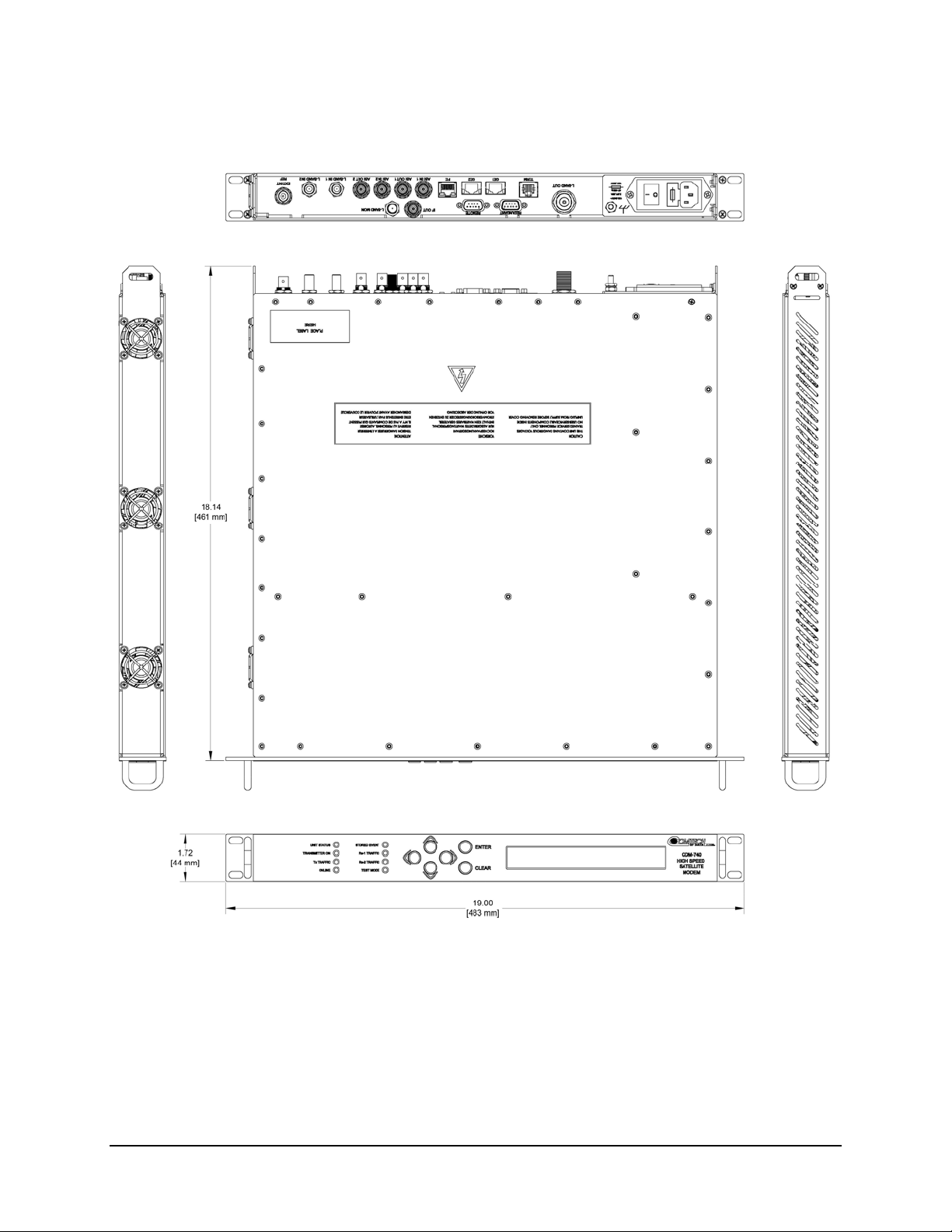
Figure 1-3. CDM-740 Dimensional Envelope .......................................................................................... 1–5
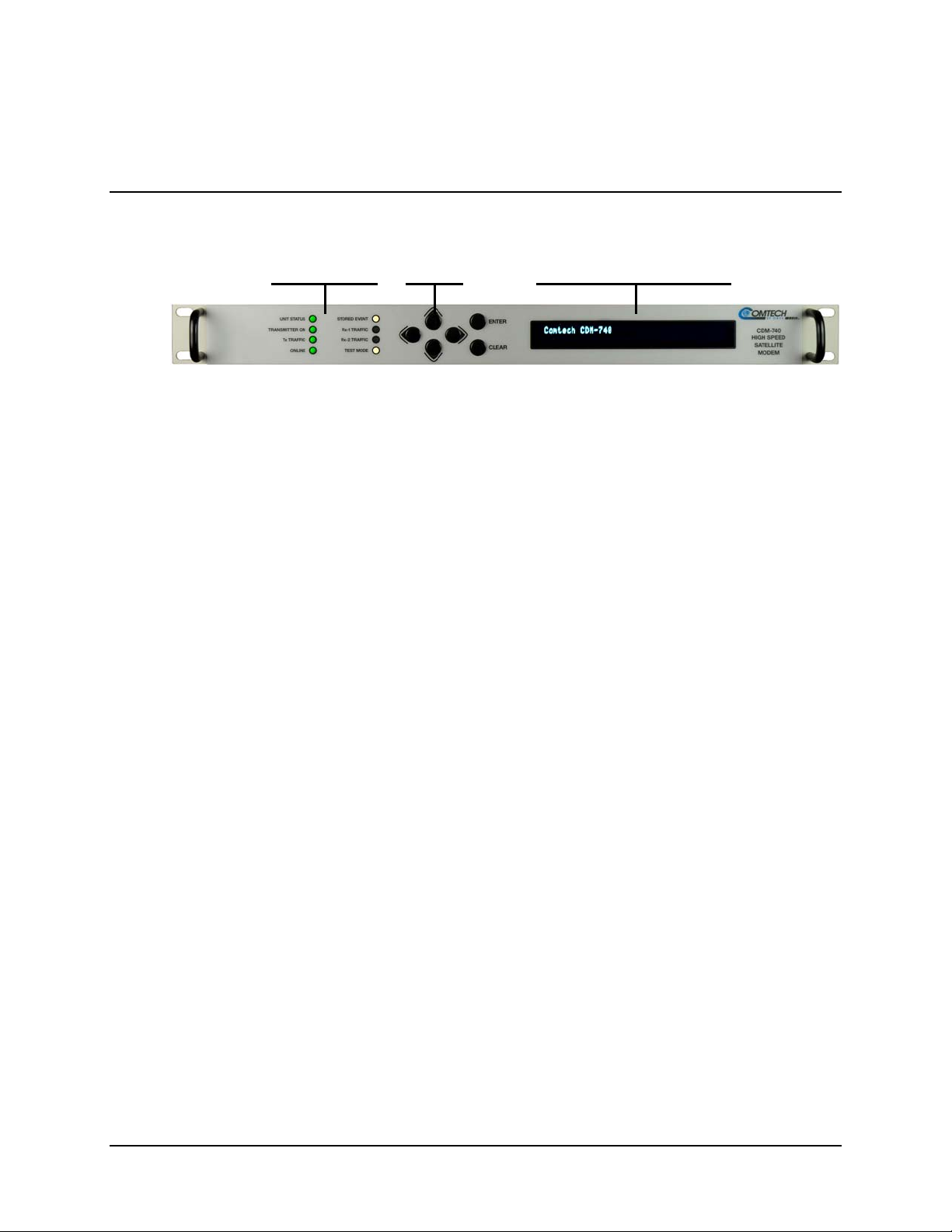
Figure 1-4. CDM-740 – Front Panel View ............................................................................................... 1–6
Figure 1-5. CDM-740 – Rear Panel View ................................................................................................ 1–7
Figure 2-1. Optional Rear-Mounting Support Bracket Installation .......................................................... 2–3
Figure 3-1. CDM-740 – Rear Panel View ................................................................................................ 3–1
Figure 4-1. Flash Update via Internet ....................................................................................................... 4–1
Figure 5-1. CDM-740 – Front Panel View ............................................................................................... 5–1
Figure 6-1. CDM-740 Advanced Satellite Modem Home (Splash) page ................................................. 6–6
Figure 6-2. Management | Main page ....................................................................................................... 6–7
Figure 6-3. Management | SNMP page ..................................................................................................... 6–9
Figure 6-4. Management | FAST page .................................................................................................... 6–10
Figure 6-5. Management | Firmware page .............................................................................................. 6–11
Figure 6-6. Management | Auto Logout page ......................................................................................... 6–12
Figure 6-7. Network | FE Management page .......................................................................................... 6–13
Figure 6-8. Network | GE-1 and GE-2 pages .......................................................................................... 6–15
Figure 6-9. DEMOD | Tuner-1 page ....................................................................................................... 6–16
Figure 6-10. Decapsulator | Tuner-1 page ............................................................................................... 6–18
Figure 6-11. Modulator page .................................................................................................................. 6–20
Figure 6-12. Statistics | Summary page ................................................................................................... 6–23
Figure 6-13. Statistics | Tuner-1 page ..................................................................................................... 6–24
Figure 6-14. Statistics | GE-1 and GE-2 pages ....................................................................................... 6–25
Figure 6-15. Statistics | Modulator page ................................................................................................. 6–26
Figure 6-16. Monitor page ...................................................................................................................... 6–27
Figure 6-17. Utility page ......................................................................................................................... 6–28
Figure C-1. CRS-175L L-Band 1:1 Redundancy Switch ......................................................................... C–1
Figure C-2. CRS-175L – 1:1 Redundancy (L-Band Simplex or Full Duplex Operation) ....................... C–2
Figure C-3. User Æ CRS-175L Æ CDM-740 IF and Control Cabling Example .................................... C–4
Figure C-4. User Æ CRS-175L Æ CDM-740 IF and Control Cabling Example .................................... C–5
Figure C-5. CDM-740 – Front Panel View .............................................................................................. C–6
Figure C-6. CDM-740 Web Server Interface Utility page ....................................................................... C–8
ix
Page 16

CDM-740 Advanced Satellite Modem Revision 0
Table of Contents MN-CDM740
This page is intentionally blank.
x
Page 17

PREFACE
About this Manual
This manual provides installation and operation information for the Comtech EF Data CDM-740
Advanced Satellite Modem. This is a technical document intended for earth station engineers,
technicians, and operators responsible for the operation and maintenance of the CDM-740.
Reporting Comments or Suggestions Concerning this Manual
Comments and suggestions regarding the content and design of this manual will be appreciated.
To submit comments, please contact the Comtech EF Data Technical Publications Department:
TechnicalPublications@comtechefdata.com
Conventions and References
Metric Conversion
Metric conversion information is located on the inside back cover of this manual. This information
is provided to assist the operator in cross-referencing non-Metric to Metric conversions.
Recommended Standard Designations
Recommended Standard (RS) Designations have been superseded by the new designation of the
Electronic Industries Association (EIA). References to the old designations are shown only when
depicting actual text displayed on the screen of the unit (RS-232, RS-485, etc.). All other references
in the manual will be shown with the EIA designations.
Trademarks
Product names mentioned in this manual may be trademarks or registered trademarks of their
respective companies and are hereby acknowledged.
xi
Page 18
CDM-740 Advanced Satellite Modem Revision 0
Preface MN-CDM740
The user should carefully observe the following information:
IMPORTANT
Cautions and Warnings
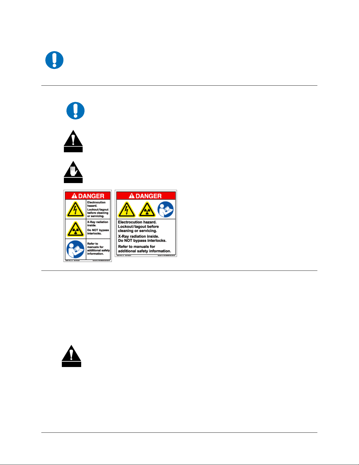
IMPORTANT or NOTE indicates a statement associated with the task being
IMPORTANT
CAUTION
WARNING
performed or information critical for proper equipment function.
CAUTION indicates a hazardous situation that, if not avoided, may result in
minor or moderate injury. CAUTION may also be used to indicate other unsafe
practices or risks of property damage.
WARNING indicates a potentially hazardous situation that, if not avoided, could
result in death or serious injury.
Examples of
Multi-Hazard Formats
Electrical Safety and Compliance
The CDM-740 has been shown to comply with the EN 60950 Safety of Information
Technology Equipment, Including Electrical Business Machines safety standard.
The equipment is rated for operation over the range 100-240 volts AC or, appropriately equipped,
36-60 volts DC. It has a maximum power consumption of 300 watts.
Fuses
FOR CONTINUED OPERATOR SAFETY, ALWAYS REPLACE THE FUSES WITH
CAUTION
The CDM-740 is fitted with two fuses – one each for line and neutral connections. These fuses
are contained within the body of the IEC power inlet connectors, behind a hinged plastic flap.
Observe the following:
THE CORRECT TYPE AND RATING.
• For 230/115 volt AC operation, use T5A 20mm slow-blow fuses.
• For 48 volt DC operation, use a T8A 20mm blow-blow fuses.
xii
Page 19

CDM-740 Advanced Satellite Modem Revision 0
Preface MN-CDM740
Low Voltage Directive (LVD)
The following information is applicable for the European Low Voltage Directive (2006/95/EC):
Symbol Description
<HAR>
!
Symbol Definition Symbol Definition
Type of power cord required for use in the European
Community.
CAUTION: Double-pole/Neutral Fusing
ACHTUNG: Zweipolige bzw. Neutralleiter-Sicherung
International Symbols
IMPORTANT
Installation
The installation and connection to the line supply must be made in compliance to local or national
wiring codes and regulations.
The CDM-740 is designed for connection to a power system that has separate ground, line and
neutral conductors. The equipment is not designed for connection to power system that has no
direct connection to ground.
The CDM-740 is shipped with a line inlet cable suitable for use in the country of operation. If it is
necessary to replace this cable, ensure the replacement has an equivalent specification. Examples
of acceptable ratings for the cable include HAR, BASEC and HOXXX-X. Examples of
acceptable connector ratings include VDE, NF-USE, UL, CSA, OVE, CEBEC, NEMKO,
DEMKO, BS1636A, BSI, SETI, IMQ, KEMA-KEUR and SEV.
Alternating
Current
Fuse
Protective
Earth
Chassis
Ground
For additional symbols, refer to Cautions and Warnings listed earlier in this
Preface.
Environmental
The CDM-740 must not be operated in an environment where the unit is exposed to extremes of
temperature outside the ambient range 0° to 50°C (32° to 122°F); precipitation, condensation, or
humid atmospheres above 95% relative humidity; altitudes (un-pressurized) greater than 2000
metres; excessive dust or vibration; flammable gases; or corrosive or explosive atmospheres.
Operation in vehicles or other transportable installations that are equipped to provide a stable
environment is permitted. If such vehicles do not provide a stable environment, safety of the
equipment to EN60950 may not be guaranteed.
xiii
Page 20

CDM-740 Advanced Satellite Modem Revision 0
Preface MN-CDM740
Telecommunications Terminal Equipment Directive
In accordance with the Telecommunications Terminal Equipment Directive 91/263/EEC, this
equipment should not be directly connected to the Public Telecommunications Network.
CE Mark
Comtech EF Data declares that the CDM-740 modem meets the necessary requirements for the
CE Mark.
RoHS Compliance
This unit satisfies (with exemptions) the requirements specified in the European Union Directive on
the Restriction of Hazardous Substances, Directive 2002/95/EC, (EU RoHS).
EMC (Electromagnetic Compatibility) Compliance
In accordance with European Directive 89/336/EEC, the CDM-740 Modem has been shown, by
independent testing, to comply with the following standards:
Emissions: EN 55022 Class B - Limits and methods of measurement of radio
interference characteristics of Information Technology Equipment.
(Also tested to FCC Part 15 Class B)
Immunity: EN 50082 Part 1 - Generic immunity standard, Part 1: Domestic,
commercial and light industrial environment.
Additionally, the CDM-740 has been shown to comply with the following standards:
EN 61000-3-2 Harmonic Currents Emission
EN 61000-3-3 Voltage Fluctuations and Flicker
EN 61000-4-2 ESD Immunity
EN 61000-4-4 EFT Burst Immunity
EN 61000-4-5 Surge Immunity
EN 61000-4-6 RF Conducted Immunity
EN 61000-4-8 Power frequency Magnetic Field Immunity
EN 61000-4-9 Pulse Magnetic Field Immunity
EN 61000-4-11 Voltage Dips, Interruptions, and Variations Immunity
EN 61000-4-13 Immunity to Harmonics
To ensure that the Modem continues to comply with these standards, observe
IMPORTANT
the following instructions:
• Connections to the transmit and receive IF ports (BNC female connectors) should be
made using a good quality coaxial cable - for example RG58/U (50Ω or RG59/U (75Ω).
xiv
Page 21

CDM-740 Advanced Satellite Modem Revision 0
Preface MN-CDM740
• All 'D' type connectors attached to the rear panel must have back-shells that provide
continuous metallic shielding. Cable with a continuous outer shield (either foil or braid,
or both) must be used, and the shield must be bonded to the back-shell.
• The equipment must be operated with its cover on at all times. If it becomes necessary to
remove the cover, the user should ensure that the cover is correctly re-fitted before
normal operation commences.
Warrant y Policy
Comtech EF Data products are warranted against defects in material and workmanship
for a specific period from the date of shipment, and this period varies by product. In
most cases, the warranty period is two years. During the warranty period, Comtech EF
Data will, at its option, repair or replace products that prove to be defective. Repairs are
warranted for the remainder of the original warranty or a 90 day extended warranty,
whichever is longer. Contact Comtech EF Data for the warranty period specific to the
product purchased.
For equipment under warranty, the owner is responsible for freight to Comtech EF Data
and all related customs, taxes, tariffs, insurance, etc. Comtech EF Data is responsible for
the freight charges only for return of the equipment from the factory to the owner.
Comtech EF Data will return the equipment by the same method (i.e., Air, Express,
Surface) as the equipment was sent to Comtech EF Data.
All equipment returned for warranty repair must have a valid RMA number issued prior
to return and be marked clearly on the return packaging. Comtech EF Data strongly
recommends all equipment be returned in its original packaging.
Comtech EF Data Corporation’s obligations under this warranty are limited to repair or
replacement of failed parts, and the return shipment to the buyer of the repaired or
replaced parts.
Limitations of Warranty
The warranty does not apply to any part of a product that has been installed, altered,
repaired, or misused in any way that, in the opinion of Comtech EF Data Corporation,
would affect the reliability or detracts from the performance of any part of the product, or
is damaged as the result of use in a way or with equipment that had not been previously
approved by Comtech EF Data Corporation.
The warranty does not apply to any product or parts thereof where the serial number or the
serial number of any of its parts has been altered, defaced, or removed.
The warranty does not cover damage or loss incurred in transportation of the product.
The warranty does not cover replacement or repair necessitated by loss or damage from
any cause beyond the control of Comtech EF Data Corporation, such as lightning or other
natural and weather related events or wartime environments.
xv
Page 22

CDM-740 Advanced Satellite Modem Revision 0
Preface MN-CDM740
The warranty does not cover any labor involved in the removal and or reinstallation of
warranted equipment or parts on site, or any labor required to diagnose the necessity for
repair or replacement.
The warranty excludes any responsibility by Comtech EF Data Corporation for incidental or
consequential damages arising from the use of the equipment or products, or for any inability
to use them either separate from or in combination with any other equipment or products.
A fixed charge established for each product will be imposed for all equipment returned
for warranty repair where Comtech EF Data Corporation cannot identify the cause of the
reported failure.
Exclusive Remedies
Comtech EF Data Corporation’s warranty, as stated is in lieu of all other warranties,
expressed, implied, or statutory, including those of merchantability and fitness for a
particular purpose. The buyer shall pass on to any purchaser, lessee, or other user of
Comtech EF Data Corporation’s products, the aforementioned warranty, and shall
indemnify and hold harmless Comtech EF Data Corporation from any claims or
liability of such purchaser, lessee, or user based upon allegations that the buyer, its
agents, or employees have made additional warranties or representations as to product
preference or use.
The remedies provided herein are the buyer’s sole and exclusive remedies. Comtech EF
Data shall not be liable for any direct, indirect, special, incidental, or consequential
damages, whether based on contract, tort, or any other legal theory.
xvi
Page 23

CDM-740 Advanced Satellite Modem Revision 0
Preface MN-CDM740
Customer Support
Refer to p. xv in this Preface for information regarding this product’s Warranty Policy.
Contact the Comtech EF Data Customer Support Department for:
• Product support or training
• Reporting comments or suggestions concerning manuals
• Information on upgrading or returning a product
A Customer Support representative may be reached at:
Comtech EF Data
Attention: Customer Support Department
2114 West 7th Street
Tempe, Arizona 85281 USA
480.333.2200 (Main Comtech EF Data number)
480.333.4357 (Customer Support Desk)
480.333.2161 FAX
To return a Comtech EF Data product (in-warranty and out-of-warranty) for repair or replaceme nt:
• Contact the Comtech EF Data Customer Support Department. Be prepared to supply
the Customer Support representative with the model number, serial number, and a
description of the problem.
• Request a Return Material Authorization (RMA) number from the Comtech EF Data
Customer Support representative.
• Pack the product in its original shipping carton/packaging to ensure that the product
is not damaged during shipping.
• Ship the product back to Comtech EF Data. (Shipping charges should be prepaid.)
Online Customer Support
An RMA number request can be requested electronically by contacting the Customer Support
Department through the online support page at
• Click on the “Service” hyperlink, then read the “Return Material Authorization”
section for detailed instructions on our return procedures.
• Click on the “RMA Request Form” hyperlink, then fill out the form completely
before sending.
• Send e-mail to the Customer Support Department at service@comtechefdata.com.
www.comtechefdata.com/support.asp:
xvii
Page 24

CDM-740 Advanced Satellite Modem Revision 0
Preface MN-CDM740
Notes:
xviii
Page 25

1.1 Overview
The CDM-740 Advanced Satellite Modem (Figure 1-1) is Comtech EF Data’s point-to-multipoint
IP satellite modem that provides integrated DVB-S/S2 CCM and VCM demodulation with low
latency Turbo Product Coding (TPC) return modulation technology. The CDM-740 was developed
as the “spoke” or remote site equipment in hub and spoke network topologies that require high
quality, ‘always-on’ availability.
Featuring dual Gigabit Ethernet interfaces and industry-leading packet per second (pps) processing
and throughput, the CDM-740 offers the ideal platform for Internet Service Providers (ISPs),
Satellite Service Providers, Enterprise Networks, Offshore, and Broadcasters for a wide range of
applications – point-to multipoint IP networks, rapid ISP market penetration, high speed
communications, high speed content delivery (digital signage and cinema), and IPTV / business
television.
Chapter 1. INTRODUCTION
Figure 1-1. CDM-740 Satellite Modem
The CDM-740’s high-performance architecture allows efficient IP networking and transport over
satellite links while supporting a wide range of applications and network topologies. Key
operational features include:
• Transmit data rate: TPC 16 kbps to 9.98 Mbps
• Receive data rate: DVB-S/S2 up to 167 Mbps
• Transmit IF: 950 to 2150 MHz or 50 to 180 MHz
• Receive IF: 950 to 2150 MHz
• Data Interfaces: 2X 10/100/1000 BaseT Ethernet
• Management: 10/100 BaseT Ethernet with web and SNMP, EIA-232 with CLI
• Modulation types: TPC QPSK, 8-QAM, 16-QAM
• Demodulation: DVBS – QPSK; DVB-S2 – LDPC+BCH QPSK, 8-PSK, 16-APSK
• Firmware – Flash Upgrading
1–1
Page 26
CDM-740 Advanced Satellite Modem Revision 0
Introduction MN-CDM740
• 1:1 redundancy switch compatibility
• The CDM-740 front panel features a Video Fluorescent Display (VFD) and keypad for
local configuration and control; additionally, the unit may be remote-controlled.
• The CDM-740 is compact – 1RU high X 18.14” deep – and consumes 80 watts
(maximum, without BUC supply) or 300 watts (maximum, with BUC supply).
• Multiple configurations available, including receive-only and duplex.
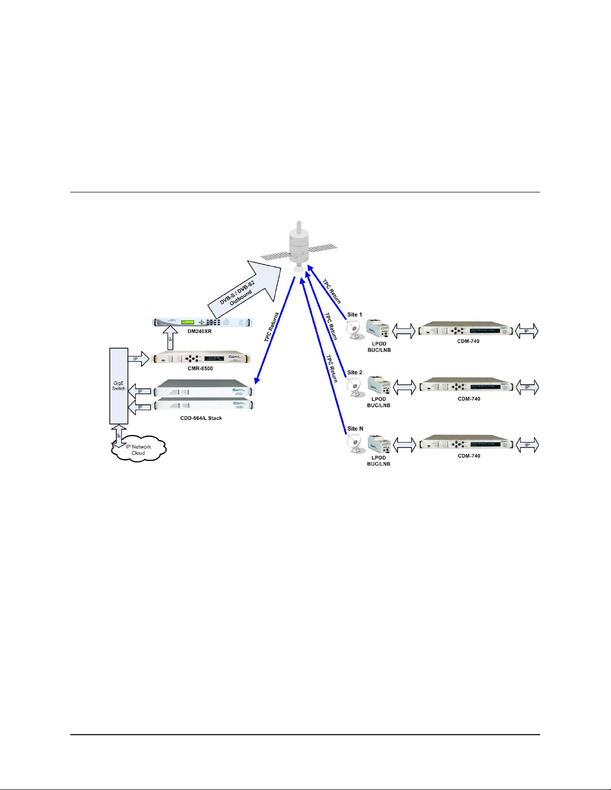
1.2 Functional Description
Figure 1-2. CDM-740 Network Topology
Figure 1-2
illustrates the CDM-740 Advanced Satellite Modem as deployed in a typical satellite-
based communications network.
The CDM-740 utilizes a high performance processor and a real-time operating system (RTOS)
combined with multiple Field Programmable Gate Arrays (FPGAs) for optimal performance. All
non-volatile memory is provided by both onboard and Compact Flash devices. Field upgrades are
easily loaded via the Ethernet port; software-based options are added to the unit via FAST (Fully
Accessible System Topology) upgrade.
The CDM-740 runs on an embedded operating system and does not have moving parts for media
storage. This design provides carrier class reliability and high speed, purpose-driven processing.
The unit can be managed through multiple interfaces providing options for both in-band and outof-band monitor and control:
• SNMP MIB II and Private MIB, HTTP Web-based Management
• Telnet (CLI), Terminal Port (CLI)
• Serial 232/485 and Front Panel control
1–2
Page 27

CDM-740 Advanced Satellite Modem Revision 0
Introduction MN-CDM740
The platform includes support for constant coding and modulation (CCM) and variable coding and
modulation (VCM) operation. VCM allows operators to define groups of remotes that can have
different modulation and coding parameters to improve efficiency on existing satellite capacity.
The CDM-740 supports reception and transmission of IP data over satellite links via two
fundamentally different types of interface – IF and data:
• The IF interface provides a bidirectional link with the satellite via the uplink and downlink
equipment.
• The data interface is a bidirectional path, which connects with the customer’s equipment
(assumed to be the DTE) and the modem (assumed to be the DCE). All terrestrial data is
connected using up to two (2) available 10/100/100 BaseT Ethernet interfaces.
On the transmit side: The return modulator transmits IP datagrams and is compatible with the
Comtech EF Data’s CDM-570/L modems and CDD-562L/564/564L demodulators located at a
hub site.
Transmit data is received by the terrestrial interface wher e line receivers convert the data signals to
CMOS levels for further processing. A small FIFO follows the terrestrial interface to facilitat e the
various framing options.
In the FEC encoder, the data is differentially encoded, scrambled, and then TPC-encoded.
Following the encoder, the data is fed to the tran smit digital filters, which perfo rm spectral sh aping
on the data signals. The resultant I and Q signals are then fed to the QPSK, 8-QAM, or 16-QAM
modulator. The carrier is generated by a frequency synthesizer, and the I and Q signals directly
modulate this carrier to produce an IF output signal.
Turbo Product Codec (TPC) Return Modulator Hardware Option: The CDM-740 has an optional
return modulator providing a very low latency SCPC return link with data rates from 16Kbps to
9.98Mbps. Available modulations are QPSK, 8-PSK and 16-QAM with FEC rates of 21/44, 3/4,
7/8 and 0.95 providing numerous options to balance power and bandwidth on duplex circuits.
On the receive side: The DVB-S / DVB-S2 demodulator supports MPE/IP Decapsulation (ETSI
EN 301 192 Multi-Protocol Encapsulation) and Program Identifier (PID) filtering for up to 256
unique PIDs.
DVB-S and DVB-S2 Receiver: The CDM-740’s demodulator supports DVB-S QPSK up to
45Msps, DVB-S2 QPSK, 8-PSK and 16-APSK demodulation up to 62 Msps with receive d ata rates
up to 167 Mbps depending on the modulation type and code rate. In DVB-S2 operation, the receiver
operates in the CCM and VCM modes. The receiver automatically detects for pilots ON/OFF and
supports spectral rolloff of 20%, 25% or 35%.
1–3
Page 28

CDM-740 Advanced Satellite Modem Revision 0
Introduction MN-CDM740
1.3 Features
1.3.1 Physical Description
The CDM-740 Advanced Satellite Modem is constructed as a 1RU-high rack-mounting chassis,
which can be free-standing if desired. Rack handles at the front to facilitate removal from and
placement into a rack.
The CDM-740 is comprised of two printed circuit board assemblies. All operational upgrades and
enhancements are afforded via remote firmware upgrade.
1.3.2 Compatibility
The CDM-740 Satellite modem transmits industry standard TPC interoperable with Comtech EF
Data’s CDM-570/L, CDM-562L, and CDM-564/L modems up to 9.98 Mbps. The receive side
supports DVB-S/S2 operation at L-Band up to 62 Msps, and is compatible with Comtech EF
Data’s CDM-710 Broadcast Satellite Modulator for CCM operation, or Comtech EF Data’s
Radyne DM240XR Digital Video Broadcast Modulator for CCM and VCM operation.
1.3.3 Major Assemblies
Assembly Description
PL-0000591 Chassis - AC
PL-0000492 PCB Main Board and Modem Card
PL-0000344 Turbo Product Code Card
1–4
Page 29
CDM-740 Advanced Satellite Modem Revision 0
Introduction MN-CDM740
1.3.4 Dimensional Envelope
Figure 1-3. CDM-740 Dimensional Envelope
1–5
Page 30
CDM-740 Advanced Satellite Modem Revision 0
Introduction MN-CDM740
1.3.5 Physical Features
1.3.5.1 Front Panel
LED
Indicators
Keypad
Vacuum Fluorescent
Display (VFD)
Figure 1-4. CDM-740 – Front Panel View
Figure 1-4 shows the front panel of t
he modem. The CDM-740 front panel features (from left):
eight LED indicators; a keypad; and a Vacuum Fluorescent Display (VFD):
• The LEDs indicate, in a summary fashion, the status of the unit.
• The user enters data via the keypad, which is comprised of six individual keyswitches
featuring a positive ‘click’ action (providing tactile feedback).
• Messages and command prompts are displayed on the VFD.
The function and behavior of the LED indicators, keypad, and VFD is described in detail in
Chapter 5. FRONT PANEL OPERATION.
1–6
Page 31

CDM-740 Advanced Satellite Modem Revision 0
Introduction MN-CDM740
1.3.6 Rear Panel
Figure 1-5. CDM-740 – Rear Panel View
Figure 1-5 s
hows the rear panel of the modem. External cables are attached to connectors on the
rear panel of the CDM-740. For a detailed descriptions/pinouts of each connector, see Chapter 3.
REAR PANEL CONNECTOR PINOUTS.
Ref Des
L-BAND OUT Type ‘N’
REDUNDANT DB-9F
REMOTE DB-9M
IF OUT BNC
L-BAND MON Type ‘F’
TERM RJ-12
GE-1, GE-2 RJ-45 (2X)
FE RJ-45
ASI IN 1
ASI OUT 1
ASI IN 2
ASI OUT 2
L-BAND IN 1
L-BAND IN 2
EXT/INT REF BNC
Connector
Type
BNC (4X)
Type ‘F’ (2X)
L-Band Transmit Output
1:1 Redundancy Interface
Remote (Tx, Rx traffic alarms and unit faults)
IF Transmit Output
L-Band Monitor Output
Terminal (EIA-232) Interface
(2) 10/100/1000 BaseT Ethernet interfaces (IEEE 802.3ab)
10/100 BaseT Ethernet interface (IEEE 802. 3u)
(2) ASI TX Outputs & (2) ASI RX Inputs
(Presently unavailable/unused)
L-Band Input 1
Presently unavailable/un used
Reference: External Input / Internal Output
Description
Note: The European EMC Directive (EN55022, EN50082-1) requires using properly shielded
cables for DATA I/O. These cables must be double-shielded from end-to-end, ensuring a
continuous ground shield.
1.3.7 Data Interfaces
The CDM-740 offers the following data interfaces:
• (2) 10/100/1000 BaseT Gigabit Ethernet Interfaces (GE1, GE2);
• A 10/100 BaseT Gigabit Ethernet Interface for management purposes (Web, SNMP, and
CLI [Command Line Interface]);
• A EIA-232/485 interface for serial modem remote control.
1.3.8 Verification
The CDM-740 includes three test modes for rapid verification of the correct function of the unit.
When normal operation is again selected, all of the previous values are restored.
1–7
Page 32

CDM-740 Advanced Satellite Modem Revision 0
Introduction MN-CDM740
1.3.9 Flash Upgrading Modem Firmware
The internal firmware is both powerful and flexible, permitting storage and retrieval of up to 10
different modem configurations. The modem uses ‘flash memory’ technology internally, and new
firmware can be uploaded to the unit from an external PC. This simplifies software upgrading,
and updates are deliverable via the Internet (from Comtech EF Data’s Web server), e-mail, or on
CD. The upgrade can be performed without opening the unit, by simply connecting the CDM-740
to the Ethernet port of a computer.
See Chapter 4. FLASH UPGRADING for further information.
1.3.10 Fully Accessible System Topology (FAST)
The CDM-740 is extremely flexible and powerful, and incorporates a large number of optional
features. In order to permit a lower initial cost, the modem may be purchased with only the desired
features enabled.
If, at a later date, a user wishes to upgrade the functionality of a modem, Comtech EF Data provides
Fully Accessible System Topology (FAST), which permits the purchase and installation of options
through special authorization codes loaded into the unit eith er via the front panel key pad or entered
remotely via the remote port located on the modem rear panel.
These unique access codes may be purchased at any time from Comtech EF Data.
FAST System Theory
FAST facilitates on-location upgrade of the operating feature set without removing a modem
from the setup.
With FAST technology, operators have maximum flexibility for enabling functions as they are
required. FAST allows an operator to order a modem precisely tailored for the initial application.
When service requirements change, the operator can upgrade the topology of the modem to meet
those requirements within minutes. This accelerated upgrade ca n be accomplished because of FAST’s
extensive use of the programmable logic devices incorporated into Comtech EF Data products.
FAST Implementation
Comtech EF Data’s FAST system is factory-implemented in the modem. All FAST options are
available through the basic platform unit at the time of order – FAST allows immediate activation of
available options, after confirmation by Comtech EF Data, through the front panel keypad or via the
remote control interface.
See Appendix C. FAST ACTIVATION PROCEDURE for further information.
FAST Accessible Options
Hardware options for basic modems can be ordered and installed either at the factory or in the
field. The operator can select options that can be activated easily in the field, depending on the
current hardware configuration of the modem. A unique access code enables configuration of the
available hardware.
1–8
Page 33

CDM-740 Advanced Satellite Modem Revision 0
Introduction MN-CDM740
The following table shows the available FAST and FAST-accessible hardware options:
Option Option Installation Method
Tx TPC Data Rate
Rx Symbol Rate FAST
Rx DVB-S2 16APSK and 32APSK FAST
Tx 70/140 MHz FAST
Tx L-Band FAST
TPC Modulator Hardware
24 VDC BUC PS
48 VDC BUC PS Hardware
FAST
Hardware
1.3.11 Supporting Hardware and Software
1:1 Redundancy Applications
The CDM-740 supports 1:1 redundancy applications via use of the optional Comtech EF Data
CRS-175L L-Band 1:1 Redundancy Switch. For further information, refer to Appendix C. 1:1
REDUNDANCY in this manual, and the CRS-175L L-Band 1:1 Redundancy Switch Installation
and Operation Manual (Comtech EF Data Document Number MN-CRS175).
1.4 New in this Release
Version 1.1.1 represents the initial product release.
1–9
Page 34

CDM-740 Advanced Satellite Modem Revision 0
Introduction MN-CDM740
1.5 Summary of Specifications
1.5.1 Transmit / Modulator
Modulation
Symbol Rate Range
Data Rate Range
Operating
Frequency Range
Frequency
Stability
Output Power
Power Accuracy
Tx Monitor Port
Phase Noise
FEC Turbo Product Codec (TPC): 6 bit soft decision, proprietary
Operating Modes TPC:
Transmit Filtering
Scrambling
External Reference In/Out See Sect. 1.5.3 Data Interfaces
Harmonics and Spurious
BUC Reference (10 MHz)
70/140 MHz
L-Band
70/140 MHz
L-Band
70/140 MHz
L-Band
70/140 MHz
L-Band
Selectable
On/Off
Monitor 70/140
Monitor L-Band
Level
Mute
70/140 MHz
L-Band
QPSK, 8-QAM and 16-QAM
4.8 ksps to 3.00 Msps, programmable in 1 sps steps
16 kbps to 9.980 Mbps, programmable in 1 bps steps
50 to 180 MHz IF, 100 Hz frequency resolution
950 to 2150 MHz L-Band, 100 Hz frequency resolution
±0.06 ppm, 0º to 50ºC (32º to 122ºF)
±0.06 ppm, 0º to 50ºC (32º to 122ºF)
-5 to -25 dBm, 0.1 dB steps
-5 to -40 dBm, 0.1 dB steps
± 1.0 dB over frequency and temperature
± 1.0 dB at 25 C over frequency and temperature
Output is L-Band.
900 MHz + IF carrier frequency
Same as L-Band frequency
-45 dBm typical
Mutes when Tx carrier is muted
< 1 degree RMS double-sided, 100 Hz to 1 MHz
< 1 degrees RMS double-sided,100 Hz to 1 MHz
• Rate 21/44 QPSK
• Rate 3/4 QPSK
• Rate 7/8 QPSK
• Rate 0.95 QPSK
• Rate 3/4 8-QAM
• Rate 7/8 8-QAM
• Rate 0.95 8-QAM
• Rate 3/4 16-QAM
• Rate 7/8 16-QAM
Note: Refer to Table 5-1 for additional data rate/symbol rate information.
IESS-308/-309 spectral mask
Comtech, IESS-315 per ITU V.35 (Intelsat variant), disabled
< -60 dBc/4 kHz over operating frequency range (Typically < -65 dBc/4 kHz)
Via Tx IF center conductor, 10 MHz per reference, selectable ON/OFF, 0 dBm ±3 dB
1–10
Page 35

CDM-740 Advanced Satellite Modem Revision 0
Introduction MN-CDM740
1.5.2 Receive / Demodulator
L-Band Input
L-Band Input Power Range
Data Decapsulation MPE/IP (ETSI EN 301 192 Multi-Protocol Encapsulation)
FEC
Operating Modes
LNB 10 MHz Reference
LNB Voltage
LNB Current Alarm
950 to 2150 MHz, Type F female
-25 to -55 dBm
LDPC+BCH: 5 bit soft decision, proprietary
DVB-S (ETSI EN 300 421):
• Rate QPSK 1/2
• Rate QPSK 2/3
• Rate QPSK 3/4
• Rate QPSK 5/6
• Rate QPSK 7/8
DVB-S2 (ETSI EN 302 307):
• Rate QPSK 1/4 • Rate 8-PSK 9/10
• Rate QPSK 1/3 • Rate 16-APSK 3/5
• Rate QPSK 1/2 • Rate 16-APSK 2/3
• Rate QPSK 3/5 • Rate 16-APSK 3/4
• Rate QPSK 2/3 • Rate 16-APSK 5/6
• Rate QPSK 3/4 • Rate 16-APSK 8/9
• Rate QPSK 5/6 • Rate 16-APSK 9/10
• Rate QPSK 8/9 • Rate 32-APSK 3/5
• Rate QPSK 9/10 • Rate 32-APSK 2/3
• Rate 8-PSK 3/5 • Rate 32-APSK 3/4
• Rate 8-PSK 2/3 • Rate 32-APSK 5/6
• Rate 8-PSK 3/4 • Rate 32-APSK 8/9
• Rate 8-PSK 5/6 • Rate 32-APSK 9/10
• Rate 8-PSK 8/9
Note: Refer to Table 5-2 through Table 5-4 for additional data rate/symbol rate
information.
On center conductor of L-Band input connector, selectable ON/OFF.
Level: -3dBm ± 3 dB.
Source: either Internal modem reference or External reference
Performance: For phase noise, refer to L-Band modulator 10 MHz Frequency
stability same as the modulator 10 MHz reference.
On center conductor of L-Band input connector, selectable ON/OFF, 13, 18 volts
per DiSEq 4.2 and 24VDC at 500 mA maximum.
Programmable MIN and MAX current alarms.
1–11
Page 36

CDM-740 Advanced Satellite Modem Revision 0
Introduction MN-CDM740
1.5.3 Data Interf aces
IF Transmit Output
L-Band Transmit Output
L-Band Input
L-Band Monitor Output
External Reference
In/out
Remote Control
1:1 Control
Ethernet Management
Ethernet
1 70/140 MHz Transmit Output port BNC (female)
1 L-Band Transmit Output port Type ‘N’ (female)
1 L-Band Input port Type ‘F’ (female)
1 L-Band Monitor Output port Type ‘F’ ( female)
As an input:
1, 2, 5 or 10MHz -6dBm to +10dBm (nominal 50/75 Ω)
As an output:
10MHz, 2.7 volts peak-to-peak +/- 0.4 volts, low impedance output
EIA-232 terminal interface for modem remote control and monitoring 9-pin D-sub (male)
Control interface for CRS-175L 1:1 Redundancy unit;
Tx, Rx traffic alarms and Unit faults
1 port of 10/100 BaseT auto-sensing full/half duplex Ethernet RJ-45
2 ports of 10/100/1000 BaseT auto-sensing full/half duplex Ethernet RJ-45
1.5.4 Data Rate Ranges
Refer to Table 5-1 through Table 5-4 for data rate/symbol rate information.
BNC (female)
9-pin D-sub (male)
1–12
Page 37

CDM-740 Advanced Satellite Modem Revision 0
Introduction MN-CDM740
1.5.5 Miscellaneous
Front Panel
Dimensions
Weight
M&C Interface
M&C Software
Monitor Functions
Firmware update
AC consumption
AC operating voltage
DC consumption (optional)
DC operating voltage
Operating temperature
Storage temperature
Humidity
• 8 LED Indicators:
Unit Status (Red/Green)
Transmitter On (Green)
Tx Status (Green)
Online (Green)
• Tactile keypad – 6 keys (Up, Down, Left, Right, Enter, Clear)
• Vacuum Fluorescent Display (blue) – 2 lines of 40 characters
1.75” (44 mm) [1RU] high x 19” (480 mm) wide x 18.41 inches (467.61 mm) deep
(all dimensions approximate)
12 lbs (5.45 kgs) max (48V BUC supply installed)
EIA-232 or Ethernet (10/100 BaseT)
Serial comms, SNMP, Telnet, Web Server (http)
• Live Alarms: Unit, Tx, Rx
• Stored Events: Up to 255 events (View/Clear)
• Rx Parameters:
o Es/No estimate:
2 to 10 dB with ± 0.3 dB accuracy
0 to 16 dB with ± 0.5 dB accuracy
o Corrected Bit Error Rate: 1E-3 to 1E-10
• IP Operating Statistics: Mod/Demod, GE1, GE2 (View/Clear)
Via Ethernet port, FTP protocol
50 watts (typical) / 80 watts (maximum), no BUC
270 watts (24 volt BUC supply installed) / 300 watts (maximum)
270 watts (48 volt BUC supply installed) / 300 watts (maximum)
100 - 240 volts AC, 47Hz-63Hz IEC 320 input
(total absolute max. range is 90 - 254 volts AC)
As above (AC consumption)
48 volts nominal (total range is 36 - 60 volts)
0º to 50ºC (32º to 122ºF)
–20° to 70°C (–4º to 158ºF)
95% maximum, non-condensing
Stored Event (Amber)
Rx-1 Traffic (Green)
Rx-2 Traffic (Green)
Test Mode (Amber)
1.5.6 Approvals
“CE” as follows:
FCC
EN 55022 Class B
(Emissions)
EN 50082-1 (Immunity)
EN 60950 (Safety)
FCC Part 15 Class B
1–13
EN 61000-3-2
EN 61000-3-3
EN 61000-4-2
EN 61000-4-4
EN 61000-4-5
EN 61000-4-6
EN 61000-4-8
EN 61000-4-9
EN 61000-4-11
EN 61000-4-13
Page 38

CDM-740 Advanced Satellite Modem Revision 0
Introduction MN-CDM740
Notes:
1–14
Page 39

Chapter 2. INSTALLATION
2.1 Unpacking and Inspection
Inspect shipping containers for damage. If shipping containers are damaged, keep them until the
contents of the shipment have been carefully inspected and checked for normal operation.
The CDM-740 Advanced Satellite Modem and its Installation and Operation Manual are packaged
and shipped in a pre-formed, reusable cardboard carton containing foam spacing for maximum
shipping protection.
Do not use any cutting tool that will extend more than 1 inch into the container.
CAUTION
Unpack and inspect the modem as follows:
Step Procedure
This can cause damage to the modem.
1
2
3
4
5
6
7
Cut the tape at the top of the carton indicated by
Remove the cardboard/foam space covering the modem.
Remove the modem, manual and power cord from the carton.
Save the packing materal for storage or reshipment puposes.
Inspect the equipment for any possible damage incurred during shipment.
Note: If damage is evident, contact the carrier and Comtech EF Data immediately
and submit a damage report.
Check the contents against the packing list to verify completeness of the
shipment.
Refer to the following sections for further installation instructions.
OPEN THIS END.
2–1
Page 40

CDM-740 Advanced Satellite Modem Revision 0
Installation MN-CDM740
2.2 Mounting
If the CDM-740 is to be mounted in a rack, ensure that there is adequate clearance for ventilation,
particularly at the sides. In rack systems where there is high heat dissipation, forced air cooling
must be provided by top or bottom mounted fans or blowers. Under no circumstance should the
highest internal rack temperature be allowed to exceed 50°C (122°F).
The CDM-740 CANNOT have rack slides mounted to the side of the chassis.
Three cooling fans are mounted in the left-hand side of the unit. Comtech EF Data
recommends that an alternate method of support within the rack be employed, such
IMPORTANT
as rack shelves or the optional rear support brackets. If there is any doubt, please
consult the Comtech EF Data Customer Support department.
2.2.1 Optional Rear-Mounting Support Bracket Installation
Install optional rear-mounting support brackets using mounting kit KT/6228-2:
Quantity Part Number Description
2 HW/10-32SHLDR Screw, #10 Shoulder
4 HW/10-32FLT Washer, #10 Flat
2 HW/10-32SPLIT Washer, #10 Split
2 HW/10-32HEXNUT Nut, #10 Hex
2 FP/6138-1 Bracket, Rear Support
4 HW/10-32x1/2RK Bolt, #10 Rack Bracket
The tools required for this installat ion are a medium Phillips™ screwdriver and a 5/32-inch SAE
Allen™ Wrench. The kit is installed as illustrated in Figure 2-1
Step Procedure
Secure the #10 shoulder screws to the unit chassis through th e rear right and left side
1
2
3
mounting slots, using the #10 flat washers, #10 split washers, and #10 hex nuts as
shown.
Install the rear support brackets onto the equipment rack threaded rear mounting
rails, using the #10 rack bracket bolts.
Mount the unit into the equipment rack, ensuring that the shoulders of the #10 shoulder
screws properly engage into the rear support bracket slots.
via the following procedure:
2–2
Page 41

CDM-740 Advanced Satellite Modem Revision 0
Installation MN-CDM740
Support Bracket
#10 Bracket Bolt
#10 Shoulder Screw
#10 Flat Washer
#10 Flat Washer
#10 Split Washer
Equipment Rack
Rear Mounti ng Ra il
#10 Hex Nut
Back of unit
Figure 2-1. Optional Rear-Mounting Support Bracket Installation
2–3
Page 42

CDM-740 Advanced Satellite Modem Revision 0
Installation MN-CDM740
Notes:
2–4
Page 43

Chapter 3. REAR PANEL
CONNECTOR PINOUTS
3.1 Connector Overview
The rear panel connectors for the CDM-740 Advanced Satellite Modem, shown here in Figure
3-1, provide all necessary external connections between the modem and other equipment.
Table 3-1 on the
grouped according to service function.
next page summarizes the connectors provided on the rear panel interface,
Figure 3-1. CDM-740 – Rear Panel View
3–1
Page 44

CDM-740 Advanced Satellite Modem Revision 0
Rear Panel Connector Pinouts MN-CDM740
Table 3-1. CDM-740 Rear Panel Connectors
Connector
Group
IF
Sect. 3.2
Terrestrial Data
Sect. 3.3
Utility
Sect. 3.4
Power/Ground
Sect 3.5
Name (Ref Des) Connector Type Function
L-BAND IN 1
L-BAND IN 2 (UNUSED) UNUSED
L-BAND OUT Type ’N’ female (L-Band)
IF OUT BNC female (70/140 MHz)
GE1
GE2
FE (Fast Ethernet) RJ-45 female
ASI IN 1
ASI
(UNUSED)
TERM RJ-12 Female Terminal (EIA-232) Interface
REDUNDANT 9-pin Type ‘D’ female
REMOTE 9-pin Type ‘D’ male
L-BAND MON Type ‘F’ female L-Band Monitor Output
EXT/INT REF BNC female
AC See Sect. 3.5.1 Chassis power
DC See Sect. 3.5.2 Chassis power (optional)
Ground #10-32 stud Common Chassis Ground
ASI OUT 1
ASI IN 2
ASI OUT 2
Type ’F’ female (L-Band)
RJ-45 Female
BNC female
IF Rx Input
IF Tx Output
10/100/1000 BaseT Ethernet
Traffic Interface
10/100 BaseT management and
data
UNUSED
Connection to External 1:1
Controller
Serial Remote Interface
(EIA-232/485)
10 MHz External/Internal
Reference Input/Output
3–2
Page 45

CDM-740 Advanced Satellite Modem Revision 0
Rear Panel Connector Pinouts MN-CDM740
3.2 IF Connections
There may be DC voltages present on the Type ‘N’ Rx and Tx IF connectors, up
CA UTIO N
to a maximum of 48 volts.
3.2.1 Rx IF Connectors
Ref Des Connector
L-BAND IN 1 Type ‘F’ Rx IF signal, L- Band In
L-BAND IN 2 Type ‘N’
3.2.2 Tx IF Connectors
Ref Des
L-BAND OUT Type ‘N’ Tx IF signal, L- Band
IF OUT BNC
L-BAND MON Type ‘F’
3.3 Terrestrial Data Connections
Type
Connector
Type
Description Direction
(UNUSED) (UNUSED)
Description Direction
Tx IF signal,
70/140 MHz band
L-Band Monitor of
70/140 or L-Band
Out
3.3.1 GE-1 and GE-2 Ethernet Connectors, RJ-45
These are two standard RJ-45 female modular jacks, operating at 10/100/1000
Mbps, half and full duplex, auto-negotiating.
Note: The maximum Ethernet pa cket size is 1522 bytes (including Ethernet
headers and CRC).
3.3.2 FE (Fast Ethernet) Connector, RJ-45
This is a standard RJ-45 female modular jack, operating at 10/100 Mbps, half and full
duplex, auto-negotiating.
Note: The maximum Ethernet packet size is 1522 bytes (including Ethernet headers
and CRC).
3–3
Page 46

CDM-740 Advanced Satellite Modem Revision 0
Rear Panel Connector Pinouts MN-CDM740
3.3.3 ASI IN/OUT 1 & 2 Connectors, BNC (UNUSED)
This BNC connector group is unused. All information in this
section is provided for reference only.
3.4 Utility Connections
3.4.1 TERM Connector, RJ-12
The TERM Connector is a standard 6-pin RJ-12 female modular jack. It is used for
management of CDM-740 and IP functions using a terminal emulator connected
(with the supplied adapter cable) to the Console port. This is a EIA-232 DCE
interface. Refer to Table 3-2 for the con
Table 3-2. TERM Connector Pin Assignments
Pin # Function
nector pinouts.
1 Ground
2 Rx
3 Tx
4 Ground
5 Not used
6 Not used
3.4.2 REDUNDANT Connector, DB-9F
The Redundant connector is a 9-pin Type ‘D’ female connector, intended only
for connection to a CRS-175L L-Band 1:1 Redundancy Switch. Refer to Table 3-3
for pino
uts.
Table 3-3. REMOTE Connector Pinouts
Pin # Description Direction
1 Ground
2 Receive Serial Data – auxiliary channel In
3 Redundancy In 1 In
4 Redundancy In 2 In
5 Ground
6 Transmit Serial Data – auxiliary channel Out
7 Redundancy Out 1 Out
8 Redundancy Out 2 Out
9 Fused +12 volt Out
3–4
Page 47

CDM-740 Advanced Satellite Modem Revision 0
Rear Panel Connector Pinouts MN-CDM740
3.4.3 Remote Control Interface Connector, DB-9M
The Remote Control Interface is a 9-pin Type ‘D’ male connector. It is
intended for connection to an M&C computer or terminal device, and is user
selectable for either EIA-232 or EIA-485. Refer to Table 3-4 for
pinouts.
Table 3-4. Remote Control Connector Pinouts
Pin # Description Direction
1 Ground –
2 EIA-232 Transmit Data Out
3 EIA-232 Receive Data In
4 Reserved - do not connect to this pin –
5 Ground –
6
7
8 EIA-485 Transmit Data B Out
9 EIA-485 Transmit Data A Out
EIA-485 Receive Data B *
EIA-485 Receive Data A *
In
In
* Use for 2-wire EIA-485 operation
3.4.4 EXT/INT REF Connector, BNC
The Ext/Int Ref connector is a BNC female connector. The signal supplied here
by the user is used for phase-locking the internal 10MHz reference oscillator, and
can be 1, 2, 5, 10 or 20 MHz. The impedance is matched for 50/75Ω, and requires
a level in the range –6 to +10 dBm.
Connector Type Description Direction
BNC External Reference In/Out
3–5
Page 48

CDM-740 Advanced Satellite Modem Revision 0
Rear Panel Connector Pinouts MN-CDM740
3.5 Power / Ground Connections
3.5.1 Alternating Current Power Connector
A standard, detachable, non-locking, 3-prong power cord (IEC
plug) supplies the Alternating Current (AC) power to the modem
via this connector.
Note the following:
AC Power Specifications
Input Power 40W maximum, 20W typical
Input Voltage
Connector Type IEC
Fuse Protection 5.0A Slow-blow (115 volt AC operation)
100 - 240 volts AC, +6%/-10% - autosensing
(total absolute max. range is 90 - 254 volts AC)
2.5A Slow-blow (230 volt AC operation)
Line and neutral fusing
(2) 20 mm type fuses
3.5.2 Direct Current (DC) Power Connector (Optional)
This optional connector supplies the Direct Current (DC) power to
the modem.
Note the following:
DC Power Specifications
Input Power
Input Voltage
Connector Type Corcom PS series
Mating Connector Corcom GA210 or Molex 03-12-1026
Fuse Protection 8A Slow-blow
48 watts (typical)
55 watts (maximum)
48 volts DC, nominal
(36 volts to 60 volts)
Line and neutral fusing
(2) 20 mm type fuses
3.5.3 Chassis Ground Connector
A #10-32 stud adjacent to the power connector is used for connecting a common
chassis ground among equipment.
Note: The AC power connector provides the safety ground.
3–6
Page 49

Chapter 4. FLASH UPGRADING
4.1 Flash Updating via Internet
Because the CDM-740 Satellite Modem uses integrated ‘Flash memory’ technology, the need for
updating firmware by physically replacing EPROMs is eliminated. This makes software upgrading
very simple, and updates can n ow be sent via the Inte rnet ( Figure 4-1),
This chapter outlines the complete upgrading process as follows:
• New firmware can be downloaded via the Internet to an external PC.
• The upgrade can be performed without opening the CDM-740 by simply connecting the unit
to the Ethernet port of a co mputer.
• The firmware update is transferred, via File Transfer Protocol (FTP), to the CDM-740.
via E-mail, or on CD.
Figure 4-1. Flash Update via Internet
4–1
Page 50

CDM-740 Advanced Satellite Modem Revision 0
Flash Upgrading MN-CDM740
4.2 Ethernet FTP Upload Procedure
1. Identify the reflashable product, firmware number, and version for download.
The current base modem M&C version can be viewed at the top level menu of the front
panel display (press the CLEAR key several times to view). The firmware information can
also be found within the (Select) Utility: Firmware Æ Info Æ BootRom, Image#1 or
Image#2 menu trees.
Using serial remote control, the firmware revision levels can be queried with the
following commands:
Abbreviated: <0/SWR?
or:
Detailed: <0/FRW?x where: x = 0 (Boot), 1 (Image 1) or 2 (Image 2)
For more information about remote commands, see Appendix A. REMOTE CONTROL.
Alternately, when using the Web Server Interface, the Bootrom, Image1 and Image2
firmware loads may be viewed after selecting the Firmware Info hyperlink (available
under the Status page tab). For more information, refer to Chapter 6.5 Web Server
(HTTP) Interface.
2. Create a temporary directory (folder) on an external PC.
Windows: Select File > New > Folder, then rename the New Folder to "temp" or another
convenient, unused name. Assuming "temp" works, a "c:\temp" folder should now be
created.
Note: The c: is the drive letter used in this example. Any valid writable drive letter can
be used.
CMD Prompt: At the command prompt (c:\>), type "mkdir temp” or “MD temp" without
quotes (mkdir and MD stand for make directory). This is the same as creating a new folder
from Windows. There should now be a "c:\temp" subdirectory created (where c: is the
drive letter used in the example).
3. Download the correct firmware file to this temporary folder. As shown in Figure 4-1:
1. Go online to: www.comtechefdata.com
2. Click on: Support tab
3. Click on: Software Downloads drop-down or hyperlink from Support page
4. Click on: Download Flash and Software Update Files icon
5. Click on: (Select a Product Line) Satellite Modems hyperlink
6. Select the CDM-740 product hyperlink
7. Select the appropriate firmware hyperlink.
About Firmware Numbers, File Versions, and Formats: The flashable files on the download
server are organized by product prefix; firmware number (verify that the correct firmware
number is known – see Step 1); revision letter, if applicable; and release version. The base
modem bulk firmware for the CDM-740 is FW-0000279X_V### (where ‘X’ denotes the
revision letter, and ‘###’ the firmware version).
The current version firmware release is provided. If applicable, one version prior to the
current release is also available. Be sure to identify and download the desired version.
4–2
Page 51

CDM-740 Advanced Satellite Modem Revision 0
Flash Upgrading MN-CDM740
The downloadable files are stored in two formats: *.exe (self-extracting) and *.zip
(compressed). Some firewalls will not allow the downloading of *.exe files. In this case,
download the *.zip file instead.
For additional help with "zipped" file types, refer to PKZIP for Windows, WinZip, or
ZipCentral help files. PKZIP for DOS is not supported due to file naming conventions.
4. Extract the files into the temporary folder on the PC. At least two files should be extracted:
• FW-0000279x.bin, where "x" is the version (bulk image file).
• CDM-740_ReleaseNotes_vXXX.pdf, where “XXX” denotes the firmware version.
5. Confirm that the files have been extracted to the specified temporary folder on the PC. In
DOS, use “cd c:\temp” to change to the temporary directory created in Step 2, then use the
“dir” command to list the files extracted from the downloaded archive file.
6. Connect the external PC to any one of the four CDM-740 modem 10/100 Ethernet ports, via
a hub or a switch, or directly to a PC with a crossover cable.
7. Send a “ping” command to the modem to verify the connection and communication.
First, determine the IP address of the modem remotely or using the front panel:
• Remotely - use the <0/IPA? command
• Front panel - use the
SELECT: Config Æ IP Æ GE1 / GE2 / Mgmt ÆAddr/Range
menu.
Then, using DOS to PING (and FTP): Click “Start” on the Windows toolbar, then select the
“Run...” option. As an alternative, use the “DOS Prompt” or “Command Prompt” icons in
the Start Menu:
• Using Win95 or Win98: Type “command”.
• Using WinNT, Win2K or WinXP: Type “cmd”.
At the DOS prompt, type “ping xxx.xxx.xxx.xxx” (where "xxx.xxx.xxx.xxx" is the modem IP
address). The results should confirm whether or not the modem is connected and
communicating.
8. Initiate an FTP session with the modem (the example uses a DOS window):
a. From the PC, type "ftp xxx.xxx.xxx.xxx" where "xxx.xxx.xxx.xxx" is the IP address of
the CDM-740.
b. Press ENTER at the user prompt.
c. Verify the FTP transfer is binary by typing "bin".
d. Type "prompt" then type "hash" to facilitate the file transfers.
9. Transfer the files: Type "put FW-0000279*.bin:" to begin the file transfers. It will take a
few seconds to transfer the file.
10. Verify the file transfer.
a. The PC should report that the file transfer has occurred, and the display on the
modem will report:
... FTP Upgrade In Progress ...
... Please wait ...
4–3
Page 52

CDM-740 Advanced Satellite Modem Revision 0
Flash Upgrading MN-CDM740
b. The upgrade will take several minutes. When it has finished, the modem front panel
will return to its normal display.
c. Terminate the FTP session by typing "bye" and closing the DOS window.
d. Verify that the new file loaded using the procedure in step 1.
e. Change the desired image to boot from the modem font panel menu:
Utility Æ Firmware Æ Select
; use the right or left arrows (◄►) on the front panel
SELECT:
keypad to select Latest, #1, or #2, then press ENTER.
f. Verify the new software versions are booting by observing the following messages
on the modem display:
Comtech CDM-740 Advanced Satellite Modem
TPC installed Ver1.1.1
4–4
Page 53
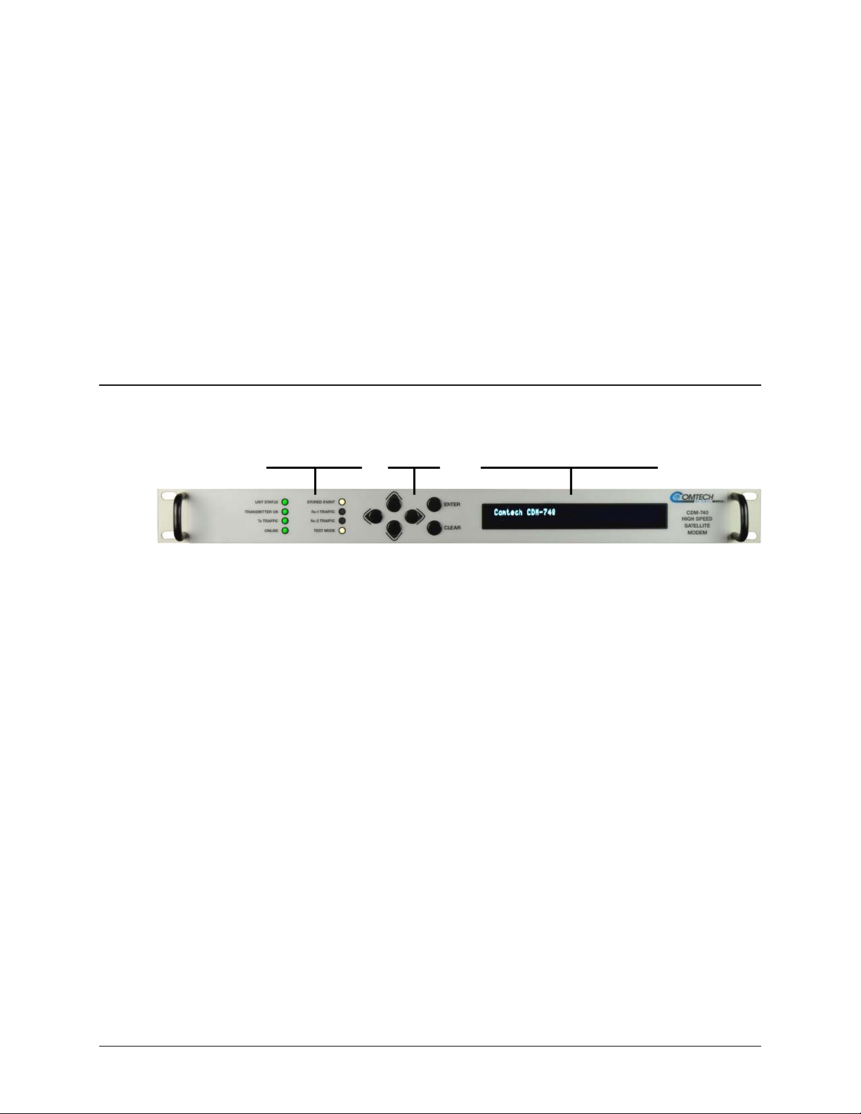
5.1 Description
Chapter 5. FRONT PANEL
OPERATION
The user can fully control and monitor the operation of the CDM-740 Advanced Satellite Modem
from the front panel using the keypad and display. Nested menus are used, which display all
available options, and prompt the user to carry out a required action.
Figure 5-1 identifies the key
this section.
LED
Indicators
Figure 5-1. CDM-740 – Front Panel View
features of the front panel, which are explained in greater detail in
Keypad
Vacuum Fluorescent
Display (VFD)
5–1
Page 54

CDM-740 Advanced Satellite Modem Revision 0
Front Panel Operation MN-CDM740
5.1.1 Front Panel LED Indicators
IMPORTANT
In general, the Alarm relay state will reflect the state
of the Front Panel LEDs. For instance, if the Unit
Status LED is red, the Unit Alarm relay will be active,
etc. The one exception is the Transmit Traffic relay.
This will only be activated if a Transmit Traffic Fault
exists – it does not reflect the state of the Tx carrier.
The function of the eight front panel LED indicators is as follows:
LED Condition
Green No Unit Faults, or Traffic Faults
UNIT STATUS
TRANSMITTER ON
Tx TRAFFIC
ONLINE
STORED EVENT
Rx-1 TRAFFIC
Rx-2 TRAFFIC (Unused) (Unused)
TEST MODE
Amber No Unit Faults, but a Traffic Fault exists
Red A Unit Fault exists (Example: PSU fault)
Green Transmitter is ON
Off Transmitter is OFF. May be forced OFF by a Fault or programmed OFF
Green No Tx Traffic Faults (data, encoder, synthesizer and modulator all OK)
Off A Tx Traffic fault exists
Green The Unit is Online, and carrying traffic
Off The Unit is Offline (standby) – forced by externally connected 1:1 redundancy system
Amber
Off There are no Stored Events
Green No Rx-1 Traffic Faults (demod-1 and data are all are OK)
Off
Amber A Test Mode is selected (Example: TX CW)
Off There is no currently selected Test Mode
There is a Stored Event in the log, which can be viewed from the front panel, or retrieved
via the remote control interface
An Rx-1 Traffic fault exists (the demod may still be OK)
Or Rx-1 is inactive and not enabled (programmed OFF)
5.1.2 Front Panel Keypad
The keypad has an auto-repeat feature. If a key is held
down for more than 1 second, the key action will repeat,
IMPORTANT
The function of the keypad is as follows:
◄ ► (Left, Right)
▲ ▼ (Up, Down)
ENTER
CLEAR
5–2
These arrows are used to move to the next selection or to move the cursor functions.
At times, they may also used to move from one section to another.
These arrows are used primarily to change configuration data (numbers).
At times, they may also be used to move from one section to another.
This key is used to select a displayed function or to execute a modem configuration change.
This key is used to back out of a selection or to cancel a configuration change which has not been
executed using [ENTER]. Pressing [CLEAR] generally returns the display to the previous selection.
automatically, at the rate of 15 keystrokes per second.
This is particularly useful when editing numeric fields,
with many digits, such as frequency or data rate.
Page 55

CDM-740 Advanced Satellite Modem Revision 0
Front Panel Operation MN-CDM740
5.1.3 Front Panel Vacuum Fluorescent Display (VFD)
The CDM-740 features a Vacuum
Fluorescent Display (VFD). The VFD
is an active display showing two lines
of 40 characters each. It produces a blue light, the brightness of which can be controlled by the
user. Compared to a Liquid Crystal Display (LCD), it has greatly superior viewing characteristics
and does not suffer problems of viewing angle or contrast.
On most menu screens, the user will observe a flashing solid block cursor, which blinks at a onceper-second rate. This indicates the currently selected item, digit, or field. Where this solid block
cursor would obscure the item being edited (e.g., a numeric field) the cursor will automatically
change to an underline cursor.
If the user were to display the same screen for weeks at a time, the display could become ‘burnt’
with this image. To prevent this, the unit has a ‘screen saver’ feature that activates after 1 hour:
CDM740 Ver1.1.1
...... PRESS ANY KEY ......
The message moves from right to left across the screen, then wraps around. The top line of the
display identifies the product (i.e., the CDM-740) with the running firmware version or the
Circuit ID (which can be entered by the user).
The bottom line reads ‘
Pressing any key will restore the previous screen.
...... PRESS ANY KEY ......’.
5.2 Front Panel Menu
The table on the next page illustrates the hierarchal structure of the front panel menu tree, and
provides a quick references for the chapter sections provide detailed explanations about the available
front panel menu, menu branch, and submenu selections.
5.2.1 Opening Screen
This ‘welcome’ screen is displayed whenever power is first applied to the unit. The modem model
(i.e., the CDM-740), installed options, and the running firmware version are indicated here:
Comtech CDM-740 Advanced Satellite Modem
TPC installed Ver1.1.1
Press any key to go to the Select: (Main) menu screen.
5–3
Page 56

CDM-740 Advanced Satellite Modem Revision 0
Front Panel Operation MN-CDM740
5.2.2 CDM-740 Front Panel Menu Matrix
Sect. Menu / Menu Branch Submenu – Available Selections (See Chapt. Sects for nested info)
5.2.1 Opening Screen N/A
5.3 Select (Main) Menu Configuration Test Monitor Store/Ld Utility ODU FAST
5.4 Configuration Tx Rx Clocks Remote IP Misc
5.4.1 (CONFIG:) Tx Tx-IF Freq Power FEC Mod Data Scrambler*
5.4.2 (CONFIG:) Rx Rx-IF Freq FEC Demod Data Descram* Pilot*
5.4.3 (CONFIG:) Clocks Ext-Ref Int-Ref-Adj
5.4.4 (CONFIG:) Remote Local Serial Ethernet
5.4.5 (CONFIG:) IP
5.4.6 (CONFIG:) Misc High-Stab Reference Warmup Delay: Enable/Disable
5.5 Test Mode BERT-State BERT-Pattern
5.5.1 (Test:) Mode Normal Tx-CW Tx-1/0
5.5.2 (Test:) BERT-State Off On
5.5.3 (Test:) BERT-Pattern 2E23-1 2047
5.6 Monitor Live-Alarms Stored-Events Rx-Params IP-Stats
5.6.1 (Monitor:) Live-Alarms Unit Tx Rx
5.6.2 (Monitor:) Stored-Events Clear-All View
5.6.3 (Monitor:) Rx-Params EsNo BER RxLevel
5.6.4 (Monitor:) IP-Stats
5.7 Store/Ld (Store/Load Configurations) Configuration #X (0-9): Load Store
5.8 Utility Set-RTC Display-Brightness 1:1 1:N Circuit-ID Firmware
5.8.1 (Utilities:) Set-RTC
5.8.2 (Utilities:) Display-Brightness 1 .75 .50 .25
5.8.3 (Utilities:) 1:1
5.8.4 (Utilities:) 1:N (UNUSED)
5.8.5 (Utilities:) Circuit-ID (Circuit ID – max length 32 chars)
5.8.6 (Utilities:) Firmware Info Select
5.9 ODU (Outdoor Unit)
5.9.1 (BUC) BUC_LO
5.9.2 (BUC) Power
5.9.3 (BUC) 10M-Ref (BUC 10MHz Reference): Off/On
5.9.4 (BUC) Alarm
5.9.5 (BUC) Monitor
5.9.6 (LNB) LNB_LO
5.9.7 (LNB) 22K-Tone (Rx LNB 22KHz Tone): Off/On
5.9.8 (LNB) Polarity (Rx Polarity): Off Horizontal Vertical
5.10 FAST Options Configure Demo-Mode
5.10.1 (FAST) Options
5.10.2 (FAST) Config Word1 Word2 Word3
5.10.3 (FAST) Demo-Mode Off/On
(IP): GE1 GE2 Mgmt
(SNMP): Read-Cmty Write-Cmty Trap
View: Mod/Demod GE1 GE2
Clear: Mod Demod GE1/GE2 All
(Time): (hh/mm/ss)
(Date): (dd/mm/yy)
(Press ENTER to force switchover to standby unit)
(UNUSED)
(BUC): BUC_LO Power 10M-Ref Alarm Monitor
(LNB): LNB_LO 22K-Tone Polarity
(BUC Lockout Frequency) (MHz)
(Terminal Mix:) +/- TTF
(BUC Power Enable): Off/On
(Output Power Enable): Off/On
(Alarm Limit Low): (mA)
(Alarm Limit High): (mA)
Read-only (BUC Power Monitor) (mA, V)
(LNB Lockout Frequency) (MHz)
(Terminal Mix) +/- RTF
Read-only
5–4
Page 57

CDM-740 Advanced Satellite Modem Revision 0
Front Panel Operation MN-CDM740
* Note: Config: Tx Æ Scrambler, Config: Rx Æ Descram, and Config: Rx Æ Pilot selections are active only if the Mode selection is DVB-S2.
5.3 SELECT: (Main) Menu
Select: Configuration Test Monitor
Store/Ld Utility ODU FAST (◄►)
Use the ◄ ► arrow keys to select from the choices shown, then press ENTER. The following
table identifies the menu branch, its content section in this chapter, and the functional description
of each branch:
Menu Branch Sect
Configuration 5.4
Test 5.5
Monitor 5.6
Store/Ld 5.7
Utility 5.8
ODU 5.9
FAST 5.10
Description
Permits user to fully configure the modem.
Permits user to configure the modem into one of several Test modes, and configures/monitors the
BER Tester.
Permits user to monitor the current status of the modem and view the log of stored events for the
modem.
Permits user to store configured parameters into one of 10 memory locations and load (recall)
those configurations at a later time.
Permits user to set operational features such as time and date, display brightness, redundancy,
Circuit ID, or Firmware boot image selection.
(Outdoor Unit) Permits user to monitor and control a Comtech EF Data RF Transceiver (BUC
[Block Up Converter] or LNB [Low-noise Block Down Converter]) , if connected.
(Fully Accessible System Topology) Permits user to configure different options, for extended
data rates, interfaces, etc. Contact Comtech EF Data Customer Support for details.
5–5
Page 58

CDM-740 Advanced Satellite Modem Revision 0
Front Panel Operation MN-CDM740
5.4 SELECT: Configuration
CONFIG: Tx Rx Clocks Remote IP
Misc (◄►)
Use the ◄ ► arrow keys to select from the submenu choices shown, then press ENTER. The
submenus available from the Configuration menu branch are as follows:
Submenu Sect Description
(Transmit) Permits the user to define, on a parameter-by-parameter basis, the Tx configuration of
Tx 5.4.1
Rx 5.4.2
the unit. These menu submenu branches would be used if the user wished to change, for example,
just the Tx Frequency.
(Receive) Permits the user to define, on a parameter-by-parameter basis, the Rx configuration of
the unit. These menu submenu branches would be used if the user wished to change, for example,
just the Rx data rate.
Clocks 5.4.3
Remote 5.4.4
IP 5.4.5
Misc 5.4.6
Only one method of remote access may control
modem may be monitored over the remote control bus at any time (i.e.,
IMPORTANT
queries only), and the front panel may be viewed.
To make configuration parameter changes from the front panel, local mode is
required. Via serial remote, remote mode is required, and via IP, Ethernet
remote is required.
5.4.1 CONFIG: Tx
Tx-IF Freq Power FEC Mod Data Scrambler
(Data 9980.000kbps, 2851.429ksym) (◄►)
Select IF, Freq, Power, FEC, Mod, Data, or Scrambler using the ◄ ► arrow keys, then press
ENTER.
(Clocking) Permits the usder to select internal or external frequency clocking modes.
(Remote Control) Permits the user to define whether the unit is being controlled locally, remotely,
or via IP, and to configure the serial Remote Control parameters: baud rate, I/O format, address.
Permits the user to configure various IP parameters, including IP address, gateway, SNMP, traps,
etc. plus view MAC addresses.
(Miscellaneous) Permits the user to select, view, or change various other parameters.
the modem at a time. The
5.4.1.1 (CONFIG:) Tx Æ IF
Tx: Carrier=On MonitorPort=Off
SpectrumInvert=Off (Off On) (◄►vE)
Using the ◄ ► arrow keys, select a function (Carrier, MonitorPort, or SpectrumInvert); then,
using the
5–6
▲ ▼ arrow keys, set that function as On or Off. Press ENTER when done.
Page 59

CDM-740 Advanced Satellite Modem Revision 0
Front Panel Operation MN-CDM740
When the Tx Monitor Port is turned On, an L-Band copy of the Tx carrier is provided. Note the
following:
• Monitor 70/140: Frequency = 900 MHz + programmed 70/140 MHz value;
• Monitor L-Band: Frequency = the programmed L-Band value;
• The monitor output mutes when Tx Carrier=Off.
5.4.1.2 (CONFIG:) Tx Æ Freq (Frequency)
Tx-IF Frequency: 0050.0000 MHz
(◄►E)
To edit the Tx Frequency, select each digit of the frequency to be edited using the ◄ ► arrow keys,
then edit the value of that digit using the
The available frequency ranges are 0050.0000 to 0180.0000 (50-180) MHz, and 0950.0000 to
2150.0000 (950-2150) MHz (L-Band). The resolution is 100Hz.
▲ ▼ arrow keys. Press ENTER when done.
5.4.1.3 (CONFIG:) Tx Æ Power
Output Power Level: –10.0 dBm
(◄►E)
To configure the Tx Output Power Level, select each digit to be edited using the ◄ ► arrow keys,
then edit the value of that digit using the
For Tx frequencies of 50-180 MHz, the permitted level range is –5 to –25 dBm.
For Tx frequencies of 950-2150 MHz (L-Band), the permitted level range is –5 to –40 dBm.
▲ ▼ arrow keys. Press ENTER when done.
5.4.1.4 (CONFIG:) Tx Æ FEC
Tx FEC Type: TPC (FPC)
This is a ‘status only’ message. The CDM-740 features TPC (Turbo Product Codec) as its sole
available Tx FEC type.
5.4.1.5 (CONFIG:) Tx Æ Mod (Modulation)
Mod Type=16QAM (QPSK,8QAM,16QAM)
FEC Rate=7/8 (3/4,7/8) (◄►vE)
On the top line, use the ◄ ► arrow keys to select (Tx) Mod(ulation) Type, then set the Mod Type
as QPSK, 8QAM, or 16QAM using the
navigate to (Tx) FEC Rate on the bottom line, then set the Tx FEC Rate to either 3/4 or 7/8 using
▲ ▼ arrow keys. Press ENTER when done.
the
5–7
▲ ▼ arrow keys. Next, using the ◄ ► arrow keys to
Page 60

CDM-740 Advanced Satellite Modem Revision 0
Front Panel Operation MN-CDM740
5.4.1.6 (CONFIG:) Tx Æ Data
Tx Data Rate: 9980.000 kbps
Tx Symbol Rate: 2851.429 ksps (◄►E)
To configure the Tx Data Rate (in kbps), on the top line select the digit of Data Rate to be edited
using the
ENTER when done.
The maximum limits for the Tx Data Rate are 16 kbps to 9.98 Mbps. The resolution is 1 bps.
The actual minimum and maximum data rates are dependent on Framing mode, Interface type,
Modulation type and FEC Code Rate. If the user changes any of the higher-priority parameters –
causing the data rate to become invalid – the Tx Data Rate is adjusted automatically. The upper
range of data rate will also be dictated by the FAST option(s) installed.
To configure the Tx Symbol Rate (in ksps), on the bottom line select the digit of Symbol Rate to
be edited using the ◄ ► arrow keys. Change the value of that digit using the
then press ENTER.
◄ ► arrow keys, then change the value of that digit using the ▲ ▼ arrow keys. Press
▲ ▼ arrow keys,
Refer to Table 5-1 for Tx Sy
mbol Rate and Data Rate ranges (TPC).
Table 5-1. Tx Symbol Rate / Data Rate Ranges – TPC
Modulation FEC Code Code Rate
21/44 16.762 2996.190 0.955 16.000 2860.000
QPSK Turbo
8-QAM Turbo
16-QAM Turbo
3/4 10.667 3000.000 1.500 16.000 4500.000
7/8 9.143 3000.000 1.750 16.000 5250.000
0.95 8.421 2982.105 1.900 16.000 5666.000
3/4 7.111 3000.000 2.250 16.000 6750.000
7/8 6.095 3000.000 2.625 16.000 7875.000
0.95 5.614 2982.456 2.850 16.000 8500.000
3/4 5.333 3000.000 3.000 16.000 9000.000
7/8 4.800 2851.429 3.500 16.800 9980.000
5.4.1.7 (CONFIG:) Tx Æ Scrambler
Tx Scrambler: Off Normal IESS
(◄►E)
Select Off, Normal, or IESS using the ◄ ► arrow keys, then press ENTER. Note the following:
Symbol Rate (Ksps)
Min Max Min Max
Spectral
Efficiency
Data Rate (Kbps)
• When Normal is selected, the TPC scrambler is used.
• When IESS is selected, the default ITU V.35 scrambler specified is used.
5–8
Page 61

CDM-740 Advanced Satellite Modem Revision 0
Front Panel Operation MN-CDM740
5.4.2 CONFIG: Rx
Rx-IF Freq FEC Demod Data Descram Pilot
(Data 9980.000kbps, 2851.429ksym) (◄►)
Select IF, Freq, FEC, Demod, Data, Descram, or Pilot using the ◄ ► arrow keys, then press
ENTER.
5.4.2.1 (CONFIG:) Rx Æ IF
Alpha Rolloff: .20 (.20,.25,.35)
Spectrum Invert: (◄►E)
When in DVB-S2 mode only: To set the expected filter Rx Alpha Rolloff (α) of the carrier, on
the top line select .20 (20%), .25 (25%), or .35 (35%) using the
selection is 0.20 (20%).
The Rx Alpha Rolloff (α) dictates how fast the spectral edges of the carrier are attenuated beyond
the 3 dB bandwidth. With 20% rolloff the edge falls off more quickly than with 25% and 35%.
▲ ▼ arrow keys. The default
Note: This menu is not valid in DVB-S mode, where the Rx Alpha Rolloff (α) is fixed at 35%.
To set Rx Spectrum Inversion, use the the ◄ ► arrow keys to move to the Spectrum Invert
operation on the bottom line, then set operation as On or Off using the
Once the Alpha Rolloff and Rx Spectrum Inversion settings are made, press ENTER.
5.4.2.2 (CONFIG:) Rx ÆFreq (Frequency)
Rx-IF Frequency: 0050.0000 MHz
(◄►E)
To edit the Rx-If Frequency, select each digit to be edited using the ◄ ► arrow keys, then edit the
value of that digit using the
The available frequency ranges are 0050.0000 to 0180.0000 (50-180) MHz, and 0950.0000 to
2150.0000 (950-2150) MHz (L-Band). The resolution is 100Hz.
▲ ▼ arrow keys. Press ENTER when done.
5.4.2.3 (CONFIG:) Rx Æ FEC
Rx FEC: LDPC+BCH
▲ ▼ arrow keys.
This is a ‘status only’ message. The CDM-740 features LDPC+BCH (Low-Density Parity Check
+ Bose, Chaudhuri, and Hocquengham) FEC as its sole available Rx FEC type.
5–9
Page 62

CDM-740 Advanced Satellite Modem Revision 0
Front Panel Operation MN-CDM740
5.4.2.4 (CONFIG:) Rx Æ Demod (Demodulation)
MODCOD: Auto (Auto,DVB-S)
Framing Mode=Normal (Normal,Short)(◄►vE)
On the top line, select the Demodulation type and FEC rate using the ▲ ▼ arrow keys. Selections
are as follows:
• Auto • DVB-S2 8-PSK 3/5 • DVB-S2 32-APSK 3/5
• DVB-S QPSK 1/2 • DVB-S2 8-PSK 2/3 • DVB-S2 32-APSK 2/3
• DVB-S QPSK 2/3 • DVB-S2 8-PSK 3/4 • DVB-S2 32-APSK 3/4
• DVB-S QPSK 3/4 • DVB-S2 8-PSK 5/6 • DVB-S2 32-APSK 5/6
• DVB-S QPSK 5/6 • DVB-S2 8-PSK 8/9 • DVB-S2 32-APSK 8/9
• DVB-S QPSK 7/8 • DVB-S2 8-PSK 9/10 • DVB-S2 32-APSK 9/10
• DVB-S2 QPSK 1/4 • DVB-S2 16-APSK 3/5
• DVB-S2 QPSK 1/3 • DVB-S2 16-APSK 2/3
• DVB-S2 QPSK 1/2 • DVB-S2 16-APSK 3/4
• DVB-S2 QPSK 3/5 • DVB-S2 16-APSK 5/6
• DVB-S2 QPSK 2/3 • DVB-S2 16-APSK 8/9
• DVB-S2 QPSK 3/4 • DVB-S2 16-APSK 9/10
• DVB-S2 QPSK 5/6
• DVB-S2 QPSK 8/9
• DVB-S2 QPSK 9/10
(Reserved1)
(Reserved2)
(Reserved3)
To set the FEC Framing Mode, use the the ◄ ► arrow keys to move to the Framing Mode
operation on the bottom line, then set the mode as Normal or Short using the
The default value is Normal and, when selected, enables the standard FECFRAME = 64,800 bits.
If Short is selected, it enables the 16,200 bit frame.
Note: Only DVB-S2 allows a FECRAME choice.
Once the Rx Demodulation type and FEC Framing Mode are selected, press ENTER.
5.4.2.5 (CONFIG:) Rx Æ Data
Rx Data Rate: 00009980.000 kbps (Read)
Rx Symbol Rate: 2000.000 ksps (◄►E)
To configure the Rx Data Rate (in kbps), on the top line select the digit of Data Rate to be edited
using the
ENTER when done.
The maximum limits for the Data Rate are 16 kbps to 9.98 Mbps. The resolution is 1 bps.
◄ ► arrow keys, then change the value of that digit using the ▲ ▼ arrow keys. Press
▲ ▼ arrow keys.
5–10
Page 63

CDM-740 Advanced Satellite Modem Revision 0
Front Panel Operation MN-CDM740
The actual minimum and maximum data rates are dependent on Framing mode, Interface type,
Demodulation type and FEC Code Rate. If the user changes any of the higher-priority parameters
– causing the data rate to become invalid – the Data Rate is adjusted automatically. The upper
range of data rate will also be dictated by the FAST option(s) installed.
To configure the Rx Symbol Rate (in ksps), on the bottom line select the digit of Symbol Rate to
be edited using the ◄ ► arrow keys. Change the value of that digit using the
then press ENTER.
▲ ▼ arrow keys,
On the pages that follow, refer to Table 5-2 through Table 5-4 for Rx Sy
Rate ranges (DVB-S, DVB-S2 Normal Frame, and DVB-S2 Short Frame).
5.4.2.6 (CONFIG:) Rx Æ Descram(bler) (DVB-S2 only)
Rx Descrambling Index:
Gold-n= [000000] (◄►E)
When in DVB-S2 Mode only: The Gold-n Index indicates the Physical Layer spreading
sequence number, and can be set from 0 to 262,141. The default setting is all 0s.
Edit the Gold-n Index Code by using the ◄ ► arrow keys to select the desired digit, then change
the value of that digit using the ▲ ▼ arrow keys. Press ENTER when done.
5.4.2.7 (CONFIG:) Rx Æ Pilot (DVB-S2 only)
Rx Demod Pilot: Off On
(◄►E)
When in DVB-S2 Mode only: Select the Rx Demodulator Pilot as Off or On using the ◄ ►
arrow keys, then press ENTER.
mbol Rate and Data
5–11
Page 64

CDM-740 Advanced Satellite Modem Revision 0
Front Panel Operation MN-CDM740
Table 5-2. Rx Symbol Rate / Data Rate Ranges – DVB-S
Demodulation FEC Code Code Rate
1/2
2/3 1.228758 1.228758 55.294118
3/5 1.382353 1.382353 62.205882
5/6 1.535948 1.535948 69.117647
7/8 1.612745 1.612745 72.573529
QPSK
Viterbi +
Reed-
Solomon
Symbol Rate (Msps)
Min Max Min Max
1 45
Spectral Efficiency
0.921569 0.921569 41.470588
Data Rate (Mbps)
Table 5-3. Rx Symbol Rate / Data Rate Range – DVB-S2 Normal FECFrame = 64,800 Bits
De-
modulation
QPSK
8PSK
16APSK
32APSK
FEC
Code
LDPC+
BCH
LDPC+
BCH
LDPC+
BCH
LDPC+
BCH
Inner
Code
Rate
9/10 1.788612 1.788612 110.893944 1.746049 1.746049 108.255038
9/10 2.679207 2.679207 166.110834 2.618365 2.618365 162.338630
9/10 3.567342 3.567342 167.665074 3.482680 3.482680 163.685960
9/10 4.453027 4.453027 169.215026 4.356875 4.356875 165.561250
Symbol Rate
(Msps)
Min Max Min Max Min Max
1/2
3/5 1.188304 1.188304 73.674848 1.160026 1.160026 71.921612
2/3 1.322253 1.322253 81.979686 1.290788 1.290788 80.028856
3/4 1.487473 1.487473 92.223326 1.452076 1.452076 90.028712
4/5 1.587196 1.587196 98.406152 1.549426 1.549426 96.064412
5/6 1.654663 1.654663 102.589106 1.615288 1.615288 100.147856
8/9 1.766451 1.766451 109.519962 1.724416 1.724416 106.913792
3/5
2/3 1.980636 1.980636 122.799432 1.935658 1.935658 120.010796
3/4 2.228124 2.228124 138.143688 2.177525 2.177525 135.006550
5/6 2.478562 2.478562 153.670844 2.422276 2.422276 150.181112
8/9 2.646012 2.646012 164.052744 2.585924 2.585924 160.327288
2/3
3/4 2.966728 2.966728 139.436216 2.896320 2.896320 136.127040
4/5 3.165623 3.165623 148.784281 3.090495 3.090495 145.253265
5/6 3.300184 3.300184 155.108648 3.221863 3.221863 151.427561
8/9 3.523143 3.523143 165.587721 3.439530 3.439530 161.657910
3/4
4/5 3.951571 3.951571 150.159698 3.866247 3.866247 146.917386
5/6 4.119540 4.119540 156.542520 4.030589 4.030589 153.162382
8/9 4.397854 4.397854 167.118452 4.302894 4.302894 163.509972
1 62
1 62
1 47
1 38
Spectral
Efficiency
Pilot OFF
0.988858 0.988858 61.309196 0.965327 0.965327 59.850274
1.779991 1.779991 110.359442 1.739569 1.739569 107.853278
2.637201 2.637201 123.948447 2.574613 2.574613 121.006811
3.703295 3.703295 140.725210 3.623332 3.623332 137.686616
Data Rate (Mbps)
Pilot OFF
Spectral
Efficiency
Pilot ON
Data Rate (Mbps)
Pilot ON
5–12
Page 65

CDM-740 Advanced Satellite Modem Revision 0
Front Panel Operation MN-CDM740
Table 5-4. Rx Symbol Rate / Data Rate Range – DVB-S2 Short FECFrame = 16,200 Bits
De-
modulation
QPSK
8PSK
16APSK
32APSK
FEC
Code
LDPC+
BCH
LDPC+
BCH
LDPC+
BCH
LDPC+
BCH
Inner
Code
Rate
1/2
3/5
2/3
3/4
4/5
5/6
8/9
9/10
3/5
2/3
3/4
5/6
8/9
9/10
2/3
3/4
4/5
5/6
8/9
9/10
3/4
4/5
5/6
8/9
9/10
Symbol Rate
(Msps)
Min Max Min Max
1 62
1 62
1 47
1 38
Spectral
Efficiency
Pilot OFF
0.848840 0.848840 52.628080 0.830585 0.830585 51.496270
1.156532 1.156532 71.704984 1.131661 1.131661 70.162982
1.288400 1.288400 79.880800 1.260693 1.260693 78.162966
1.420269 1.420269 88.056678 1.389725 1.389725 86.162950
1.508181 1.508181 93.507222 1.475747 1.475747 91.496314
1.596093 1.596093 98.957766 1.561768 1.561768 96.829616
1.727961 1.727961 107.133582 1.690800 1.690800 104.829600
N/A N/A N/A N/A N/A N/A
1.725319 1.725319 106.969778 1.692033 1.692033 104.906046
1.922040 1.922040 119.166480 1.884959 1.884959 116.867458
2.118761 2.118761 131.363182 2.077885 2.077885 128.828870
2.381056 2.381056 147.625472 2.335120 2.335120 144.777440
2.577778 2.577778 159.822236 2.528046 2.528046 156.738852
N/A N/A N/A N/A N/A N/A
2.548792 2.548792 119.793224 2.505223 2.505223 117.745481
2.809662 2.809662 132.054114 2.761633 2.761633 129.796751
2.983575 2.983575 140.228025 2.932574 2.932574 137.830978
3.157488 3.157488 148.401936 3.103514 3.103514 145.865158
3.418357 3.418357 160.662779 3.359924 3.359924 157.916428
N/A N/A N/A N/A N/A N/A
3.493093 3.493093 132.737534 3.419165 3.419165 129.928270
3.709309 3.709309 140.953742 3.630805 3.630805 137.970590
3.925526 3.925526 149.169988 3.842446 3.842446 146.012948
4.249850 4.249850 161.494300 4.159906 4.159906 158.076428
N/A N/A N/A N/A N/A N/A
Data Rate (Mbps)
Pilot OFF
Spectral
Efficiency
Pilot ON
Data Rate (Mbps)
Pilot ON
Min Max
5–13
Page 66

CDM-740 Advanced Satellite Modem Revision 0
Front Panel Operation MN-CDM740
5.4.3 CONFIG: Clocks
Clocking: Ext-Ref Int-Ref-Adj
(◄►E)
Select Ext-Ref or Int-Ref-Adj using the ◄ ► arrow keys, then press ENTER.
5.4.3.1 (CONFIG:) Clocks Æ Ext-Ref
External Frequency Reference:
Int10 Ext1 Ext2 Ext5 Ext10 10+Output
Select Int10, Ext1, Ext2, Ext5, Ext10, or 10+Output using the ◄ ► arrow keys, then press
ENTER. Note the following:
Selection Description
Int10
Ext1
Ext2
Ext5
Ext10
10+Output
Internal Reference selection is available at 10 MHz.
The unit phase locks to the external input at the rear panel BNC connector labeled EXT REF for External 1,
2, 5, or 10 MHz input.
The Internal 10 MHz Reference is available via the rear panel BNC connector labeled EXT REF.
5.4.3.2 (CONFIG:) Clocks Æ Int-Ref-Adj
Internal Hi-Stability 10Mhz Reference
Fine Adjust: +000 (+/-999) (◄►E)
Fine adjustment of the Internal 10 MHz reference oscillator is possible through this menu. Use
▲ ▼ arrow keys to edit both the sign ( + [positive] or – [negative]) and the value. The range
the
of values is from –999 to +999.
Note: The numbers displayed here do not correspond to an exact frequency increment. A user
should perform this fine adjustment while using an external frequency counter, connected to either:
a) the internal 10 MHz reference, if the user has internal access to the equipment,
or
b) the Tx Output, set for CW, 0 dBm output level, and an exact center frequency (1000
MHz, for example).
In order for this operating parameter to be retained, the user must save this
configuration in any one of the 10 available modem configurations (SELECT:
Æ
IMPORTANT
Utility
value will be reset.
Save/Load). Otherwise, when the CDM-740 power is cycled, this
5–14
Page 67

CDM-740 Advanced Satellite Modem Revision 0
Front Panel Operation MN-CDM740
5.4.4 CONFIG: Remote
Remote Control= Local Serial Ethernet
(◄►E)
Select Local, Serial, or Ethernet using the ◄ ► arrow keys, then press ENTER.
If Local is selected, then reconfiguration via Serial Remote or Ethernet is not permitted.
Remote monitoring is still possible.
5.4.4.1 (CONFIG:) Remote Æ Serial
Serial 485 Address: 0001
Baud Rate: 38400(Read only) (◄►vE)
To edit the Serial 485 Address, select each digit of the Address using the ◄ ► arrow keys, then edit
the valuve of that digit using the
range is 0001 to 9999.
▲ ▼ arrow keys. Press ENTER when done. The permitted address
Note: Address 0 is reserved for universal addressing. Character format is not selectable and is fixed
at 8-N-1.
5.4.5 CONFIG: IP
IP Config: GE1 GE2 Mgmt
SNMP: Read-Cmty Write-Cmty Trap (◄►)
On the top line, select GE1, GE2, or Mgmt using the ◄ ► arrow keys, then press ENTER to edit
the pertinent IP Configuration parameters. Note that, with the exception of the screen label, the
function of these three IP configuration submenus is identical. For brevity, all three are explained
next in Sect. 5.4.5.1.
On the bottom line, using the ◄ ► arrow keys to select the SNMP Configuration parameter to edit
(Read-Cmty, Write-Cmty, or Trap). Refer to Sect. 5.4.5.2 through Sect. 5.4.5.4 for further
details.
5–15
Page 68

CDM-740 Advanced Satellite Modem Revision 0
Front Panel Operation MN-CDM740
5.4.5.1 (CONFIG:) IP Æ (GE1 / GE2 / MGMT)
GE1: Addr/Range MAC Gateway
Link-Config NegoSpeed (◄►)
GE2: Addr/Range MAC Gateway
Link-Config NegoSpeed (◄►)
MANAGEMENT: Addr/Range MAC Gateway
Link-Config NegoSpeed (◄►)
Select Addr/Range, MAC, Gateway, Link-Config, or NegoSpeed using the ◄ ► arrow keys,
then press ENTER.
(CONFIG:) IP Æ (GE1 / GE2 / MGMT) Æ Addr/Range
[HEADER] Ethernet IP Address/Range:
192.168.001.002/24 (◄►E)
Where [HEADER] is GE1, GE2, or MANAGEMENT: To configure the IP Address for the
Ethernet M&C port for this interface, use the ◄ ► arrow keys to select the character to edit, then
▲ ▼ arrow keys to edit the value of that digit. Press ENTER when done.
the
(CONFIG:) IP Æ (GE1 / GE2 / MGMT) Æ MAC
[HEADER] Ethernet MAC Address (Read-Only)
00-06-B0-00-01-06 (◄►E)
Where [HEADER] is GE1, GE2, or MANAGEMENT: This is a ‘status only’ display showing the
interface MAC address. Exit this read-only screen by pressing ENTER or CLEAR.
(CONFIG:) IP Æ (GE1 / GE2 / MGMT) Æ Gateway
[HEADER] Ethernet IP Gateway:
192.168.001.002 (◄►E)
Where [HEADER] is GE1, GE2, or MANAGEMENT: To edit the IP Gateway Address for the
Ethernet M&C port for this interface, use the ◄ ► arrow keys to select the character to edit, then
use the
▲ ▼ arrow keys to edit the value of that digit. Press ENTER when done.
(CONFIG:) IP Æ (GE1 / GE2 / MGMT) Æ Link-Config
[HEADER] Link Configuration:
Auto 1000F 100F 100H 10F 10H (◄►E)
Where [HEADER] is GE1, GE2, or MANAGEMENT: To configure the line speed and duplex
setting for this interface, use the ◄ ► arrow keys to select the configuration setting, then press
ENTER.
5–16
Page 69

CDM-740 Advanced Satellite Modem Revision 0
Front Panel Operation MN-CDM740
Note the following:
Selection Description
Auto
1000F
100F
100H
10F
10H
The port will auto-negotiate the configuration of the port (recommended
when the configuration of the port is unknown)
1000 Mb / Full Duplex
100 Mb / Full Duplex
100 Mb / Half Duplex
10 Mb / Full Duplex
10 Mb / Half Duplex
(CONFIG:) IP Æ (GE1 / GE2 / MGMT) Æ NegoSpeed
[HEADER] Negotiated Speed (read-only)
Down 1000F 100F 100H 10F 10H (◄►E)
Where [HEADER] is GE1, GE2, or MGMT( MANAGEMENT): This is a ‘status only’ display
showing the negotiated line speed and duplex setting for this interface. Exit this read-only screen
by pressing ENTER or CLEAR.
Note the following:
Selection Description
Down
1000F
100F
100H
10F
10H
Ethernet is disconnected
1000 MB / Full Duplex
100 MB / Full Duplex
100 MB / Half Duplex
10 MB / Full Duplex
10 MB / Half Duplex
5.4.5.2 (CONFIG:) IP Æ (SNMP) Read-Cmty
SNMP Read Community (Max 15 chars)
[public ] (◄►E)
To edit the SNMP Read Community string, use the ◄ ► arrow keys to select the character to edit,
then use the
Note: Only the first 15 characters on the bottom line are available.
All printable ASCII characters are available with the exception of the backslash (ASCII code 92)
and ~ (ASCII code 126).
▲ ▼ arrow keys to select the desired character.
Once the string has been composed, press ENTER. All trailing spaces are removed from the
Read Community string upon entry.
5–17
Page 70

CDM-740 Advanced Satellite Modem Revision 0
Front Panel Operation MN-CDM740
5.4.5.3 (CONFIG:) IP Æ (SNMP) Write-Cmty
SNMP Write Community (Max 15 chars)
[private ] (◄►E)
To edit the SNMP Write Community string, use the ◄ ► arrow keys to select the character to
edit, then use the
Note: Only the first 15 characters on the bottom line are available.
All printable ASCII characters are available with the exception of the backslash (ASCII code 92)
and ~ (ASCII code 126).
Once the string has been composed, press ENTER. All trailing spaces are removed from the
Write Community string upon entry.
▲ ▼ arrow keys to select the desired character.
5.4.5.4 (CONFIG:) IP Æ SNMP Æ Trap
SNMP Trap IP:
000.000.000.000 (◄►E)
This menu permits the user to edit the Trap Destination’s IP Address. Use the ◄ ► arrow keys to
select the character to edit, then use the
Trap IP Address is 000.000.000.000, it means Trap is disabled.
5.4.6 CONFIG: Misc
High-Stab Reference Warm-Up Delay:
Disable Enable (◄►E)
The High-Stability Reference Module contains an oven for the crystal. It can take a little time for the
oven & crystal to come up to temperature; during this time, the frequency accuracy is not
guaranteed. The warm-up delay is calculated by the modem, based on temperature and the amount
of time the unit was turned off. This is much more important at L-Band (950-2150 MHz) than at
50-180 MHz, where the 10 MHz reference may also be used for RF conversion equipment.
Use the ◄ ► arrow keys to Disable or Enable a Warm-up Delay, which will be implemented on
power-up. Press ENTER when done.
▲ ▼ arrow keys to edit the value of the character. If the
5–18
Page 71

CDM-740 Advanced Satellite Modem Revision 0
Front Panel Operation MN-CDM740
5.5 SELECT: Test
TEST: Mode BERT Pattern
(◄►)
Select Mode, BERT, or Pattern using the ◄ ► arrow keys, then press ENTER.
5.5.1 TEST: Mode
Modem Test Mode: Normal Tx-CW Tx-1/0
(◄►E)
Select Normal operation, Tx-CW, or Tx-1/0 using the ▲ ▼ arrow keys, then press ENTER.
Note the following:
Selection Description
(Normal) This clears any test modes and places the unit back into an
Normal
operational state.The TEST MODE LED on the CDM-740 front panel will turn
OFF.
Tx-CW
Tx-1/0
5.5.2 TEST: BERT
Tx BERT State: Off On
(◄►E)
Set the Tx BERT State as On or Off using the ◄ ► arrow keys, then press ENTER. When On is
selected, the Test Mode LED on the CDM-740 front panel will turn ON.
5.5.2.1 TEST: Pattern
Tx BERT Pattern: 2E23-1 2047
(◄►E)
(Transmit CW) This is a test mode that forces the modulator to transmit a pure
carrier (unmodulated). The TEST MODE LED on the CDM-740 front panel will
turn ON.
(Transmit an alternating 1,0,1,0 pattern) This test mode forces the modulator
to transmit a carrier modulated with an alternating 1,0,1,0 pattern at the currently
selected symbol rate. This causes two discrete spectral lines to appear, spaced
at +/- half the symbol rate about the carrier frequency. This mode is used to
check the carrier suppression of the Modulator. The TEST MODE LED on the
CDM-740 front panel will turn ON.
Select 2E23-1 or 2047 using the ◄ ► arrow keys, then press ENTER. Note the following:
Selection Description
2E23-1
2047
5–19
A pseudo-random data pattern of 2E23 –1, compatible with standard BERTs.
A pseudo-random data pattern of 2E11 –1, compatible with standard BERTs.
Page 72

CDM-740 Advanced Satellite Modem Revision 0
Front Panel Operation MN-CDM740
5.6 SELECT: Monitor
Monitor: Live-Alarms Stored-Events
Rx-Params IP-Stats (◄►)
Select Live-Alarms, Stored-Events, Rx-Params, or IP-Stats using the ◄ ► arrow keys, then
press ENTER
.
5.6.1 Monitor: Live-Alarms
Live Alarms Unit=Unit OK
Tx=Traffic OK Rx=Demod Unlocked
An example of an Alarm screen is shown. Three alarm types are available. The highest priority
alarm currently active for each of the alarm types is as follows:
a = Unit status:
0 = No faults
1 = Power supply fault, +5 volts
2 = Power supply fault , +12 volts
3 = Power supply fault, +3.3 volts
4 = Tx synthesizer unlocked
5 = Tx FPGA PLL unlocked
6 = Modulator FPGA load fail
7 = TPC/LDPC FPGA load fail
8 = Reference unlocked (Note: Tx off)
9 = Unit Temperature Exceeded
b = Tx Traffic status:
0 = Tx traffic OK
1 = Tx FIFO slip
2 = Tx 130 MHz PLL unlocked
3 = (Hi-Stab) No External Ref found (no activity)
c = Rx 1 Traffic status:
0 = Rx Traffic OK
1 = Demodulator unlocked
2 = Rx FIFO Overrun
5–20
Page 73

CDM-740 Advanced Satellite Modem Revision 0
Front Panel Operation MN-CDM740
5.6.2 Monitor: Stored-Events
Stored Events: Clear-All View
(◄►E)
Select View or Clear-All using the ◄ ► arrow keys, then press ENTER.
5.6.2.1 (Monitor:) Stored-Events Æ Clear-All
Clear All Stored Events: No Yes
(◄►)
Use the ◄ ► arrow keys to select Yes or No. Press ENTER when done.
If Clear-All=Yes is selected, the event log is cleared and the user is returned directly to the
previous menu. However, if there already are faults present on the unit at this time, they will be
re-time-stamped, and new log entries will be generated.
5.6.2.2 (Monitor:) Stored-Events Æ View
Event 006(v): 01/01/09 00:00:00:24
Clear Unit FEC card
An example of a Stored Events screen is shown.
The event log can store up to 255 events. When a fault condition occurs, it is time- & datestamped and put into the log. Similarly, when the fault condition clears, this is also recorded.
Note that, in accordance with international convention, the date is shown in DAY-MONTH-
YEAR format.
Use the
▲ ▼ arrow keys to scroll up and down through the event log entries. Press ENTER or
CLEAR to return to the previous menu.
5.6.3 Monitor: Rx-Params
Rx Parameters: EsNo=99.9
BER=9999 RxLevel=LT-90
This read-only screen provides the active Rx Parameters mode information as follows:
Item Description
Displays the value of Es/No calculated by the demodulator. The value
EsNo
referred to here is the energy per symbol bit (Es), divided by the noise
spectral density (No).
BER
RxLevel
5–21
Displays an estimate of the corrected Bit Error Rate.
Displays the dBm reading indicating the signal level of the desired receive
carrier. Resolution: 0.5dB
Page 74

CDM-740 Advanced Satellite Modem Revision 0
Front Panel Operation MN-CDM740
5.6.4 Monitor: IP-Stats
View: Mod/Demod GE1 GE2
Clear: Mod Demod GE1/GE2 All (◄►)
To view IP operating statistics: From the top line of the Monitor: IP-Stats menu, select
Mod/Demod, GE1, or GE2 using the ◄ ► arrow keys, then press ENTER. Examples of the
Mod/Demod and GE statistics screens (where GE# represents GE1 or GE2) are as follows:
View(v): Demod: 2300
Pkts Mod: 2400
GE# STATS(v) IN: 2440
Pkts OUT: 2112
For all menus, use the ▲ ▼ arrow keys to scroll through the available statistics. For a list of the
statistics available on these, refer to the table on the following page. Press ENTER or CLEAR to
exit the screen and return to the previous menu.
To clear IP operating statistics: From the bottom line of the Monitor: IP-Stats menu, select
Mod, Demod, GE1/GE2, or All using the ◄ ► arrow keys, then press ENTER.
For any selection, when prompted select No or Yes using the ◄ ► arrow keys, then press
ENTER, as per the following example:
Clear All Stats: No Yes
(◄►E)
Monitor: IP Æ Stats Submenus – Available Statistics Summary
Statistic Description
Pkts
Max Data Rate
Data Rate
MC Dropped
UC Dropped
Dropped
Multicast
Unicast
Number of packets.
Maximum Data Rate.
Current Data Rate.
Multicast packets dropped.
Unitcast packets dropped.
Total packets dropped.
Multicast packets sent/received
Unitcast packets sent/received.
Mod/Demod GE1 GE2
Submenu
X X X
X X X
X X X
X
X
X
X X X
X X X
N/A N/A
N/A N/A
N/A N/A
5–22
Page 75

CDM-740 Advanced Satellite Modem Revision 0
Front Panel Operation MN-CDM740
5.7 SELECT: Store/Ld
Configuration #2: Load Store
AVAILABLE (◄►vE)
The user can store up to 10 different modem configurations, numbered 0 through 9.
Select the configuration location number using the
using the
As a modem configuration is stored, the time and date is recorded. This time and date information
is shown on the bottom line as the location number is selected. A memory location that is
available is noted on the bottom line as AVAILABLE.
◄ ► arrow keys. Press ENTER when done.
▲ ▼ arrow keys, then select Load or Store
(Store/Load:) Override
Whether storing a configuration into a location or loading a configuration into the working
memory from a stored location, the user is required to confirm the request, as information will be
overwritten:
Configuration #2. Override? No Yes
14:06:37 26/10/06 (◄►E)
Select the Override choice (No or Yes) using the ◄ ► arrow keys, then press ENTER.
5–23
Page 76

CDM-740 Advanced Satellite Modem Revision 0
Front Panel Operation MN-CDM740
5.8 SELECT: Utility
Utilities: Set-RTC Display-Brightness
1:1 1:N Circuit-ID Firmware (◄►E)
Select Set-RTC, Display-Brightness, 1:1, 1:N, Circuit-ID, or Firmware using the ◄ ► arrow
keys, then press ENTER
.
5.8.1 Utilities: Set-RTC
Time: 12:01:02 hh:mm:ss
Date: 26/10/06 dd/mm/yy (◄►E)
To edit the time and date settings of the RTC (Real-Time Clock), select the digit to be edited using
the ◄ ► arrow keys, then edit the value of that digit using the
when done.
Note that in accordance with international convention, the date is shown in
IMPORTANT
DAY-MONTH-YEAR format.
▲ ▼ arrow keys. Press ENTER
5.8.2 Utilities: Display-Brightness
Display Brightness: 1 .75 .50 .25
(◄►)
To edit the brightness of the VFD (Vacuum Fluorescent Display), use the the ◄ ► arrow keys to
select a suitable brightness level. The selectable values are 1 (100%), .75 (75%), .50 (50%), or .25
(25%). Press ENTER when done.
5.8.3 Utilities: 1:1
Press ENTER key to force unit into
Standby (1:1 only)
The CDM-740 automatically detects the presence of a CRS-175L L-Band 1:1 Redundant Switch.
If Utility: 1:1 is selected and this unit is currently online and part of a 1:1 redundant modem pair
operating in tandem with a CRS-175L switch, the user is prompted to press ENTER (as indicated
above); this command then automatically forces the switchover of operation to the standby unit.
If, however, 1:1 is selected from the Utility menu branch and no CRS-175L switch is detected,
the following error message displays:
... Error ...
No Valid Redundancy
For detailed information about 1:1 redundant operation, refer to Appendix C. 1:1 REDUNDANCY
in this manual.
5–24
Page 77

CDM-740 Advanced Satellite Modem Revision 0
Front Panel Operation MN-CDM740
5.8.4 Utilities: 1:N (UNUSED)
The CDM-740 presently does not accommodate 1:N redundant operations; therefore, while
selectable, this submenu is non-functional
branch – regardless of the presence of a CRS-175L switch – the following error message displays:
. If, however, 1:N is selected from the Utility menu
... Error ...
No Valid Redundancy
5.8.5 Utilities: Circuit-ID
Circuit ID (max length 32)
[comtech ef data ]
This menu allow the user to enter a Circuit ID string. Use the ◄ ► arrow keys to position the
cursor on to the character to be edited, then edit the character using
following characters are available:
[Space] ( ) * + - , . / 0-9 and A-Z.
▲ ▼ arrow keys. The
Only the bottom line (32 characters) is available. Once the Circuit ID string is composed, press
ENTER.
5–25
Page 78

CDM-740 Advanced Satellite Modem Revision 0
Front Panel Operation MN-CDM740
5.8.6 Utilities: Firmware
THESE MENUS ARE FOR DIAGNOSTIC PURPOSES. ONLY CHANGE AN IMAGE
IF INSTRUCTED TO DO SO BY A COMTECH EF DATA CUSTOMER SUPPORT
IMPORTANT
This series of submenus permits the user to view information about the CDM-740 internal
firmware. The modem can store two complete firmware images, and the user can select which
image will be loaded the next time the unit reboots.
TECHNICIAN.
Firmware Images
Info Select (◄►)
Select Info or Select using the ◄ ► arrow keys, then press ENTER.
5.8.6.1 (Utilities): Firmware Æ Info
Firmware Information
BootRom Image#1 Image#2 (◄►)
Select BootRom, Image#1, or Image#2 using the ◄ ► arrow keys, then press ENTER.
(Utilities:) Firmware Æ Info Æ Bootrom
Bootrom Version (Read Only):
BSP Version: 2.0 Rev: /1)
This read-only screen displays, as shown per the example, the BootRom version number. Press
ENTER or CLEAR to exit the screen and return to the previous menu.
(Utilities:) Firmware Æ Info Æ Image#1 / Image#2
Image #X: FW-0000279 07/10/09 1.1.1
Where X represents the Image# selected: This read-only screen displays, as shown per the example,
the firmware name, its release date (in International DD/MM/YY format), and the firmware release
version number. Press ENTER or CLEAR to exit the screen and return to the previous menu.
5.8.6.2 (Utilities): Firmware Æ Select
Current Active Image is #1
Next boot will use: Latest #1 #2 (◄►E)
The top line shows the current active image. On the bottom line, the user may use the ◄ ► arrow
keys to select the other image (#1 or #2) or the firmware with the latest release date (Latest), then
press ENTER. A message shows that the unit will need to be rebooted.
5–26
Page 79

CDM-740 Advanced Satellite Modem Revision 0
Front Panel Operation MN-CDM740
5.9 SELECT: ODU
The CDM-740 modem is able to interface with various ODUs (Outdoor Units). These are:
• L-Band BUC (Block Upconverter);
• L-Band LNB (Low Noise Block Downcoverter).
The ODU configuration menus allow the user to set up power supplies, a 10 MHz reference and
low/high current alarm thresholds for the BUC and LNB. LO menus for the BUC and LNB allow
the user to set up the up-convert and down-convert parameters for the BUC and LNB so that the
user can view the satellite frequencies as well as the modem IF input/output frequencies.
BUC: BUC_LO Power 10M-Ref Alarm Monitor
LNB: LNB_LO 22K-Tone Polarity (◄►)
Use the ◄ ► arrow and ENTER keys to select a submenu. Note the following:
For Submenu Permits user to…
… enter a BUC LO (local oscillator) frequency and (+/-) sign.
… set BUC power supply parameters.
… control the BUC 10MHz Reference.
… control BUC high and low alarm limits.
… monitor BUC power supply and current parameters.
… enter an LNB LO (local oscillator) frequency and (+/-) sign.
… set the 22KHz tone outbound from L-Band connector per DiSEq 4.2
… control the LNB DC Power. Note the following:
• OFF = DC Power is off
• Horizontal is on 18V
• Vertical is on 13V.
BUC
(Top line)
LNB
(Bottom line)
BUC_LO
Power
10M-Ref
Alarm
Monitor
LNB_LO
22K-Tone
Polarity
5.9.1 ODU: (BUC:) BUC_LO
BUC_LO: 00000.000 MHz
Terminal Mix: [+] TTF: +1950.0000
On the top line, the user may enter the BUC LO frequency for the up conversion. Entering a nonzero value for BUC LO will cause the Tx-IF frequency menu to show LO and Satellite frequencies.
Edit the BUC LO frequency by using the ◄ ► arrow keys to select the digit to be edited, then use
▲ ▼ arrow keys to set the value of that digit. The valid LO range is 3000 to 65000 MHz.
the
On the bottom line, the Terminal Mix sets the polarity for the upconversion mix in the BUC:
• [+] indicates a high side, inverting mix;
• [–] indicates a low side, non-inverting mix.
Note:
Satellite frequency = LO frequency +/- modem frequency.
To set the sign for the Terminal Mix, use the ◄ ► arrow keys to navigate to the setting, then use
the
▲ ▼ arrow keys to edit the Terminal Mix setting as positive [+] or negative [–].
Note: The TTF: (Transmit Terminal Frequency) value is provided on a ‘status only’ basis.
5–27
Page 80

CDM-740 Advanced Satellite Modem Revision 0
Front Panel Operation MN-CDM740
5.9.1.1 ODU: (BUC:) Power
BUC Power Enable: Off
Output Power Enable: Off (◄►vE)
Select the power parameter to edit using the ◄ ► arrow keys, then use the ▲ ▼ arrow keys to edit
the setting as Off or On. Press ENTER when done.
5.9.1.2 ODU: (BUC:) 10M-Ref
BUC 10 MHz Reference: Off On
(◄►E)
Select the 10MHz Reference as Off or On using the ◄ ► arrow keys, then press ENTER.
Note: A BUC will not transmit without a 10MHz Reference.
5.9.1.3 ODU: (BUC) Alarm
Alarm Limit Low: 0000 mA
Alarm Limit High: 4000 mA
To set the Low and High Alarm Limits between 0 and 4000 mA, in 100mA increments, use the
◄ ► arrow keys to select the digit to be edited, then use the
that digit. Press ENTER when done. The default values (mA) are (low) #### and (high) ####.
5.9.1.4 ODU: (BUC) Monitor
BUC Power Monitor:
0000 mA, 00.1 V
This read-only display provides the BUC power supply current and voltage information. Press
ENTER or CLEAR to return to the previous menu.
5.9.1.5 ODU: (LNB) LNB_LO
LNB_LO: 00000.000 MHz
Terminal Mix: [+] RTF: +1950.0000
On the top line, the user may enter the LNB LO frequency for the down conversion. Entering a nonzero value for LNB LO will cause the Rx-IF frequency menu to show LO and Satellite frequencies.
Edit the LNB LO frequency by using the ◄ ► arrow keys to select the digit to be edited, then use
▲ ▼ arrow keys to set the value of that digit. The valid LO range is 3000 to 65000 MHz.
the
On the bottom line, the Terminal Mix sets the polarity for the downconversion mix in the LNB:
▲ ▼ arrow keys to set the value of
• [+] indicates a high side, inverting mix;
5–28
Page 81

CDM-740 Advanced Satellite Modem Revision 0
Front Panel Operation MN-CDM740
• [–] indicates a low side, non-inverting mix.
Note:
Satellite frequency = LO frequency +/- modem frequency.
To set the sign for the Terminal Mix, use the ◄ ► arrow keys to navigate to the setting, then use
▲ ▼ arrow keys to edit the Terminal Mix setting as positive [+] or negative [–].
the
Note: The RTF: (Receive Terminal Frequency) value is provided on a ‘status only’ basis.
5.9.1.6 ODU: (LNB) 22K-Tone
Rx LNB 22KHz Tone: Off On
(◄►E )
Select the LNB 22KHz Tone as Off or On using the ◄ ► arrow keys, then press ENTER.
5.9.1.7 ODU: (LNB) Polarity
Rx Polarity: Off Horizontal Vertical
(◄►E )
Select the Rx Polarity as Off, Horizontal, or Vertical using the ◄ ► arrow keys, then press
ENTER. Note the following:
• Horizontal corresponds to 18 volts (or LHCP);
• Vertical corresponds to 13 volts (or RHCP).
5–29
Page 82

CDM-740 Advanced Satellite Modem Revision 0
Front Panel Operation MN-CDM740
5.10 SELECT: FAST
FAST: Options Configure Demo-Mode
Baseboard S/N 100000004 (◄►E )
FAST (Fully Accessible System Topology) is the way to enable new options in the modem.
Available FAST options include:
► Tx Freq Range: IF70-140 MHz
► Tx TPC Data Rate: 16-9980 kbps
► Tx FEC: TPC
► Rx FEC/Symbol Rate: DVBS to 45 Msps / DVBS2 to 62 Msps
► Rx Demodulation: DVBS / DVBS2 / QPSK / 8PSK / 16APSK / 32 APSK
► CCM
On the top line, select the Options, Configure, or Demo-Mode using the ◄ ► arrow keys, then
press ENTER.
The bottom line provides the CDM-740’s baseboard serial number. This number is required when
contacting Comtech EF Data Customer Support to purchase any FAST upgrades.
5.10.1 FAST: Options
Demod Support
CCM (v)
Use the ▲ ▼ arrow keys to scroll through the listings of available FAST option displays, similar
to the above example. Each FAST option is available via its own FAST unlock codes. Contact
Comtech EF Data Customer Support to obtain the FAST code for the desired option.
5.10.2 FAST: Configure
FAST Config: Word1 Word2 Word3
FAST: Configure is used to enable new options in the modem. The FAST options are accessed
via three separate internal EEPROM registers, each using its own FAST unlock code. It is
important to use the appropriate FAST unlock code for the appropriate register. Select the
correct register menu – Word1, Word2, or Word3 using the
ENTER.
◄ ► arrow keys, then press
5–30
Page 83

CDM-740 Advanced Satellite Modem Revision 0
Front Panel Operation MN-CDM740
5.10.2.1 FAST: Configure Æ Word#
FAST: Set register#: Enter code below
88888888888888888888 then [ENTER] (◄►v)
Where # represents the selected EEPROM Register # (Word1, Word2, or Word3 on the previous
menu):
Obtain the FAST code for the new option from Comtech EF Data. Enter the code carefully. Use
the ◄ ► arrow keys to move the cursor to each character, then use the
character. When all characters are edited, press ENTER.
The modem will respond with “Configured Successfully” if the new FAST option has
been accepted; otherwise, if an invalid code is entered, the following error message is displayed:
...Error...
...Please Verify Your Input...
Carefully re-enter the code after being automatically returned to the previous menu. If the
problem persists, contact Comtech EF Data Customer Support for further assistance.
▲ ▼ arrow keys to edit the
5.10.3 FAST: Demo-Mode
FAST Options Demo Mode: Off (Off,On) (v)
1209600 seconds remaining.
When enabled, Demo Mode allows access to ALL CDM-740 FAST options for 2592000 seconds
(30 full days). Demo Mode may be turned on and off an unlimited number of time until the
2592000 seconds have expired. The time count only decrements when the mode is On.
Use the
display the number of seconds remaining for the free Demo Mode.
When the Demo period expires, the following menu is displayed:
▲ ▼ arrow keys to select Demo-Mode as Off or On. When On, the bottom line will
FAST Options Demo Mode: Expired (v)
000000 seconds remaining.
5–31
Page 84

CDM-740 Advanced Satellite Modem Revision 0
Front Panel Operation MN-CDM740
Notes:
5–32
Page 85

Chapter 6. ETHERNET
MANAGEMENT
6.1 Introduction
The CDM-740 Advanced Satellite Modem is equipped with an RJ-45, 10/100 BaseT Ethernet
management interface, labeled FE, that is used for monitor and control purposes.
This chapter provides a high-level overview of the functionality provided by this interface, and
references other chapters in this manual for further details.
6.2 Ethernet Management Interface Protocols
The modem’s 10/100BaseT Ethernet Management (FE) Interface supports three (3) different
management protocols:
• SNMP with public and private MIB;
• Telnet interface for remote product M&C;
• Web Server interface for complete product management.
6.3 SNMP Interface
The Simple Network Management Protocol (SNMP) is an application-layer protocol designed to
facilitate the exchange of management information between network devices. The CDM-740
SNMP agent supports both SNMPv1 and v2c.
For proper SNMP operation, the CDM-740 MIB files must be used with the
associated version of the CDM-740 modem M&C. Please refer to the CDM-740
IMPORTANT
FW Release Notes for information on the required FW/SW compatibility.
6–1
Page 86

CDM-740 Advanced Satellite Modem Revision 0
Ethernet Management MN-CDM740
6.3.1 Management Information Base (MIB) Files
MIB files are used for SNMP remote management and consist of Object Identifiers (OIDs). Each
OID is a node that provides remote management of a particular function. A MIB file is a tree of
nodes that is unique to a particular device.
The following MIB files are associated with the CDM-740:
MIB File/Name Description
FW10874-2-.mib
ComtechEFData
Root MIB file
FW-0000287- .mib
CDM-740 MIB file
These MIB files should be compiled in a MIB Browser or SNMP Network Monitoring System server.
ComtechEFData MIB file gives the root tree for ALL Comtech EF Data products
and consists of only the following OID:
Name: comtechEFData
Type: MODULE-IDENTITY
OID: 1.3.6.1.4.1.6247
Full
path: iso(1).org(3).dod(6).internet(1).private(4).enterprises(1).comtechEFData(
6247)
Module: ComtechEFData
MIB file consists of all of the OID’s for management of the modem functions
Note: The SNMP agent supports both “SNMPv1” and “v2c”.
6.3.2 SNMP Community Strings
The modem uses community strings as a password scheme that provides authentication before
gaining access to the modem agent’s MIBs.
In “SNMP v1/v2c”, the community string is sent unencrypted in the SNMP packets. Caution
must be taken by the network administrator to ensure that SNMP packets travel only over a
secure and private network if security is a concern. A packet sniffer can easily obtain the
community string by viewing the SNMP traffic on the network.
The community string is entered into the MIB Browser or Network Node Management software
and is used to authenticate users and determine access privileges to the SNMP agent.
The user defines two Community Strings for SNMP access:
• Read Community default = public
• Write Community default = private
6–2
Page 87

CDM-740 Advanced Satellite Modem Revision 0
Ethernet Management MN-CDM740
6.4 Telnet Interface
The modem provides a Telnet interface for the purpose of Equipment M&C via the standard
equipment Remote Control protocol.
The Telnet interface Requires user login at the Administrator level and Read/Write level.
The screen capture below shows the login process:
Once logged into the Telnet interface as t he Administr ator, the user can access the standard remot e
control interface defined in Appendix A. REMOTE CONTROL, as shown in the following
example:
6–3
Page 88

CDM-740 Advanced Satellite Modem Revision 0
Ethernet Management MN-CDM740
6.5 Web Server (HTTP) Interface
The sections that follow describe the functionality of the CDM-740 Advanced Satellite Modem
Web Server (HTTP) Interface. Please refer to Chapter 5. FRONT PANEL OPERATION,
and the Remote Commands Specifications tables found in Appendix D. REMOTE
CONTROL for detailed descriptions of the configuration parameters featured on the individual
Web pages shown in this chapter.
6.5.1 Web Server Introduction
The embedded Web Server application provides the user with an easy to use interface to
configure and monitor all aspects of the CDM-740. These Web pages have been designed for
optimal performance when using Microsoft’s Internet Explorer Version 5.5 or higher (the
examples shown use Internet Explorer Version 6.0).
The user can fully control and monitor base operations of the
CDM-740 from the Web Server Interface. The user may access an
operations page by selecting any one of the available navigation
tabs – and nested tabs, where applicable – located along the top of
each page (right).
6.5.2 Web Server Menu Tree
The menu tree illustrates the options available through this interface:
Home Management Network Demod Decap MOD Statistics Monitor Utility
Main FE Mgt Tuner-1 Tuner-1 Summary
SNMP GE-1 Config Tuner-1
FAST GE-2
Firmware
Auto Logout Modulator
Status
Utilities
GE-1
GE-2
6–4
Page 89

CDM-740 Advanced Satellite Modem Revision 0
r
r
Ethernet Management MN-CDM740
6.5.3 User Login
To initiate a Web session with the CDM-740 Modem, from the PC type http://xxx.yyy.zzzz (where
“xxx.yyy.zzz” represents the IP address of the CDM-740 Advanced Satellite Modem) into the
Address area of the Web browser:
The Login window will appear, and the user is prompted to type a User Name and Password:
Note the following:
HTTP Login Access Levels
User Interface
Web
Admin User Read/Write Use
No Access to Admin or
Full Access to
all Web Pages
Encryption Web pages
Full Access for all other
User Login Access Level
Web Pages
Read Only Use
No Access to Admin or Encryption
Web pages
View Only Access for all other Web
Pages
and:
CDM-740 Advanced Satellite Modem Web Server Default Name/Passwords
User Login Access Level Default Name Default Password
Admin comtech comtech
Read/Write opcenter 1234
Read Only monitor 1234
Type the appropriate User Name and Password, then click [Log On].
6–5
Page 90

CDM-740 Advanced Satellite Modem Revision 0
•
•
•
•
•
Ethernet Management MN-CDM740
6.5.4 Web Server Page Descriptions
6.5.4.1 Home (Splash) Page
Figure 6-1. CDM-740 Advanced Satellite Modem Home (Splash) page
Once the valid User Name and Password is accepted, the user will see the CDM-740 Web Server
Interface “splash” page. From this top level menu, the user has access to nine (9) navigation tabs:
• Home
• Management
• Network
• DEMOD (Demodulator)
• DECAP (Decapsulator)
MOD (Modulator)
Statistics
Statistics
Monitor
Utility
Typical Page Features
Many of the pages in the CDM-740 Web Server Interface feature a “virtual panel” providing
‘real-time’ information as follows:
Column Function
Lock
MODCOD
Input
Port
Status
Modem Status
Es/No (dB)
BER
RSL (dbM)
Displays the LOCK STATUS of the demodulator as Locked or Unlocked.
Displays the active demodulation type and FEC rate
Displays the value of Es/No calculated by the demodulator. The value
referred to here is the energy per symbol bit (Es), divided by the noise
spectral density (No).
Displays an estimat e of the co rr e cted Bi t Erro r Ra te .
Displays the dBm reading indicating the signal level of the desired receive
carrier.
This display emulates the LED Indicator array on the CDM-740 Front
Panel, and provides the user with a ‘heads-up’ reference to the unit’s
active operational status.
Click any tab to continue.
6–6
Page 91

CDM-740 Advanced Satellite Modem Revision 0
Ethernet Management MN-CDM740
6.5.4.2 Management Pages
The ‘Management’ pages provide the means to set up the access parameters required to facilitate
communication with the CDM-740 Web Server.
The Management pages are available only to users who have logged in using
IMPORTANT
the Administrator Name and Password.
6.5.4.2.1 Management | Main Page
Figure 6-2. Management | Main page
The ‘Management | Main’ page (Figure 6-2) is used t
o configure the following CDM-740 utility
functions:
Unit Name
The product in use – in this case, the CDM-740 Advanced Satellite Modem – is identified here.
System Contact / System Location
E-mail and telephone contact information for Comtech EF Data Customer Support are provided
here.
Set Time
The user may enter a time using HH:MM:SS format (where HH = hour [00 to 23], MM = minutes
[00 to 59], and SS = seconds [00 to 59]).
6–7
Page 92

CDM-740 Advanced Satellite Modem Revision 0
•
•
Ethernet Management MN-CDM740
Set date
The user may enter a date using international format in the form DD/MM/YY (where DD = day
[01 to 31], MM = month [01 to 12], and YY = year [00 to 99]).
Circuit ID
The user may enter a Circuit ID string of up to 24 characters. Once the desired string had been
entered in this section, click [Enter Circuit ID] as needed to save this change.
External Frequency Reference
Use the dropdown menu to select the External Frequency Reference. The choices are:
• Internal 10 MHz • External 1 MHz
• External 5 MHz • External 10 MHz
External 2 MHz
Internal 10 MHz plus output
Adjustment for Internal 10 MHz High Stability Reference
Type in a value ranging from –999 to (+)999.
Once the desired configuration settings have been made in this first section, click [Submit] to
save these changes.
User Name
The User Name for the CDM-740 has a maximum of 15 characters.
Password / Confirm Password
The admin user may enter a password string of up to 24 characters. Once the desired password
string has been typed in the Password box, then re-typed as indicated in the Confirm Password
box, click [Submit] as needed to save this change.
6–8
Page 93

CDM-740 Advanced Satellite Modem Revision 0
Ethernet Management MN-CDM740
6.5.4.2.2 Management | SNMP Pa ge
Figure 6-3. Management | SNMP page
The ‘Management | SNMP’ page (Figure 6-3) sets and return
s administration information for
the CDM-740 Simple Network Management Protocol (SNMP) feature.
The Administrator can assign the following attributes:
• One SNMP Trap Destination IP Address.
Once the desired IP address has been entered, click [Submit] to save this change.
• A SNMP Read Community string. The f actory default for this parameter is public. The
SNMP Read Community string field can be any combination of character s and a length of
4 - 15 characters.
Once the desired SNMP Read Community string has been entered, click [Submit] to save
this change.
• A SNMP Write Commun ity string. The factory default for this parameter is private. Th e
SNMP Read Community string field can be any combination of characters and a length of
4 - 15 characters.
Once the desired SNMP Write Community string has been entered, click [Submit] to
save this change.
For details pertaining to the configuration parameters available on this page, refer to Chapter 5.
FRONT PANEL OPERATION and Sect. 6.3 SNMP INTERFACE.
6–9
Page 94

CDM-740 Advanced Satellite Modem Revision 0
Ethernet Management MN-CDM740
6.5.4.2.3 Management | F AS T Page
Figure 6-4. Management | FAST page
The ‘Management | FAST’ page (Figure 6-4) is a read-only pa
ge providing the summary status
of all available and/or installed Fully Accessible Sys tem Topology (FAST) operational features.
For more information on FAST, refer to the following sections in this manual:
• For an overview on FAST, see Sect. 1.3.10 in Chapter 1. INTRODUCTION.
• For details on activating FAST features via the CDM-740 front panel, refer to Sect. 5.10
in Chapter 5. FRONT PANEL OPERATION and Appendix B. FAST
ACTIVATION FEATURE.
6–10
Page 95

CDM-740 Advanced Satellite Modem Revision 0
Ethernet Management MN-CDM740
6.5.4.2.4 Management | Firmware Page
Figure 6-5. Management | Firmware page
The ‘Management | FAST’ page (Figure 6-5) permits the user to view inf
ormation about the
CDM-740 internal firmware.
Slot Information
This read-only section identifies the two available firmware configurations. Firmware name,
version, release date, file size, and the assigned slot and operational status (i.e., Running = Yes or
No) are all identified here.
Firmware Configuration
The modem can store two complete firmware images, and the user can select which image will be
loaded the next time the unit reboots.
Use the Boot From dropdown menu to select the firmware image as Latest, Slot 1, or Slot 2.
Once the desired firmware boot source has been selected, click [Submit] as needed to save this
change.
6–11
Page 96

CDM-740 Advanced Satellite Modem Revision 0
Ethernet Management MN-CDM740
6.5.4.2.5 Management | Auto Logout Page
Figure 6-6. Management | Auto Logout page
The ‘Management | Auto Logout’ page (Figure 6-6) provides a se
curity measure for
safeguarding access to a previously logged-in unit.
Once configured, the active session will be terminated when no user activity occurs within the
specified Auto Logout timeframe. A valid user name and password will then be required to open
a new session with the CDM-740 Web Server Interface.
To configure the Auto Logout feature, enter a value of 1 – 15 minutes into the Logout Time box.
Entering a value of 0 disables the Auto Logout feature. Once the desired setting has been entered,
click [Submit] to save this change.
6–12
Page 97

CDM-740 Advanced Satellite Modem Revision 0
•
•
•
Ethernet Management MN-CDM740
6.5.4.3 Network Pages
The ‘Network’ pages are used to establish the communication parameters for the FE (Fast
Ethernet) Management 10/100 BaseT interface port and the GE1/GE2 10/100/1000 BaseT
Gigabit Ethernet traffic ports.
6.5.4.3.1 Network | FE Mgt Page
Figure 6-7. Network | FE Management page
The ‘Network | FE Mgt’ page (Figure 6-7) per
10/100 BaseT Gigabit Ethernet Management Port.
mits the user to configure the Fast Ethernet
MAC Address
This parameter is read-only and cannot be changed.
IP Address / CIDR Mask
Enter the IP Address CIDR (Classless Inter Domain Routing) Subnet mask using this box.
Gateway IP
Enter the modem’s IP Gateway Address using this box.
Link Configuration
Use the dropdown menu to select the line speed and duplex setting on the CDM-740’s FE (Fast
Ethernet) interface. The available options are:
• Auto
• 1000 BaseT / Full Duplex
• 100 BaseT / Full Duplex
Note: If the configuration of the port is unknown, then “Auto” is the recommended configuration.
100 BaseT / Half Duplex
10 BaseT / Full Duplex
10 BaseT / Half Duplex
6–13
Page 98

CDM-740 Advanced Satellite Modem Revision 0
Ethernet Management MN-CDM740
Negotiated Link Mode
The read-only actual negotiated line speed and duplex setting for the FE (Fast Ethernet) interface
is displayed here. The viewable settings are:
• 100 BaseT / Full Duplex
• 100 BaseT / Half Duplex
• 10 BaseT / Full Duplex
• 10 BaseT / Half Duplex
Note: If the configuration of the port is unknown, then “Auto” is the designated configuration.
Management Gateway Port
Use the dropdown menu to select the Management Gateway Port as LAN or WAN.
Once the desired configuration settings have been made on this page, click [Submit] as needed to
save these changes.
6–14
Page 99

CDM-740 Advanced Satellite Modem Revision 0
Ethernet Management MN-CDM740
6.5.4.3.2 Network | GE-1 and GE-2 Pages
Figure 6-8. Network | GE-1 and GE-2 pages
The ‘Network | GE1’ and ‘Network | GE2’ pages (Figure 6-8) perm
it the user to configure the
communication settings for the unit’s two 10/100/1000 BaseT Gigabit Ethernet traffic ports.
With the exception of the Management Gateway Port dropdown menu (which is not included
on either of these pages), all page functionality is identical to that of the ‘Network | FE Mgt’
page. Refer back to Sect. 6.5.4.3.1 for instructions on using these pages.
6–15
Page 100

CDM-740 Advanced Satellite Modem Revision 0
Ethernet Management MN-CDM740
6.5.4.4 DEMOD (Demodulator) | Tuner-1 Page
Figure 6-9. DEMOD | Tuner-1 page
The ‘DEMOD | Tuner-1’ page (Figure 6-9) perm
demodulator operations. Note that, for any configuration item requiring text entry, a reference to
the operational ranges for that field is provided to the right of that text box.
its the user to configure CDM-740
LNB Freq (MHz)
Enter the operating frequency, in MHz, for the Low-Noise Block Downcoverter. The valid range
is from 0 – 16000 MHz.
Rx Freq (MHz)
Enter the modem’s Rx frequency, in MHz. The valid range is from 950 – 2150 MHz.
Symbol Rate (ksps)
Enter the modem’s symbol rate, in ksps. The valid range is from 1000 – 62000 ksps.
Data Rate (kbps) read-only
This is a status-only section that di splays the curren t data rate, in kbp s, as d erived from th e selected
MODCOD parameter.
MODCOD
Use the dropdown menu to select the Demodulation type and FEC rate (MODCOD).
6–16
 Loading...