

Page 1

IMPORTANT NOTE: The information contained in this document supersedes all previously published
information regarding this product. Product specifications are subject to change without prior notice.
CDM-710
Broadcast Satellite Modem
Installation and Operation Manual
CDM-710 [70-140 MHz] Broadcast Satellite Modem
CDM-710L [L-Band] Broadcast Satellite Modem
For Firmware Version 4.1.10 or Higher
Part Number MN/CDM710.IOM / CD-MNCDM710 Revision 12
Page 2

Comtech EF Data, 2114 West 7th Street, Temp e, Arizona 85 281 USA, 480.333.2200, FAX: 480.333.2161
Copyright © 2016 Comtech EF Data. A ll rights reserved. Printed in the USA.
Page 3

TABLE OF CONTENTS
TABLE OF CONTENTS ..................................................................................... III
TABLES ............................................................................................................ XII
FIGURES ......................................................................................................... XIII
PREFACE ........................................................................................................ XV
About this Manual ................................................................................................... xv
Conventions and References ................................................................................... xvi
Patents and Trademarks ............................................................................................... xvi
Warnings, Cautions, Notes, and References ................................................................. xvi
Examples of Multi-Hazard Notices ................................................................................ xvi
Recommended Standard Designations ........................................................................ xvii
Safety and Compliance ........................................................................................... xvii
Electrical Safety and Compliance ................................................................................. xvii
Class I Pluggable Equipment Type A-Protective Earthing ............................................ xvii
Galvanic Isolator Use .................................................................................................. xviii
Restricted Access Location .......................................................................................... xviii
Battery Warning .......................................................................................................... xviii
Electrical Installation ................................................................................................... xviii
Fusing xviii
Operating Environment ................................................................................................ xix
European Union Radio Equipment and Telecommunications Terminal Equipment
(R&TTE) Directive (1999/5/EC) and EN 301 489-1 ........................................................ xix
European Union Electromagnetic Compatibility (EMC) Directive (2004/108/EC) .... xix
European Union Low Voltage Directive (LVD) (2006/95/EC) .....................................xx
International Symbols ................................................................................................xx
European Union RoHS Directive (2002/95/EC) ..........................................................xx
European Union Telecommunications Terminal Equipment Directive (91/263/EEC)
.................................................................................................................................. xxi
CE Mark ..................................................................................................................... xxi
Product Support ...................................................................................................... xxi
iii
Page 4

CDM-710/L Broadcast Satellite Modem MN/CDM710.IOM / CD-MNCDM710
Table of Contents Revision 12
Comtech EF Data Headquarters ............................................................................... xxi
Warranty Policy ...................................................................................................... xxi
Limitations of Warranty ............................................................................................... xxii
Exclusive Remedies ..................................................................................................... xxiii
CHAPTER 1. INTRODUCTION .................................................................... 1–1
1.1 Overview .................................................................................................... 1–1
1.1.1 Applications .................................................................................................... 1–2
1.1.2 Standard and Optional Features ..................................................................... 1–2
1.1.2.1 Verification .............................................................................................. 1–3
1.1.2.2 Firmware Update .................................................................................... 1–4
1.1.2.3 Product Upgrade Using Fully Accessible System Topology (FAST) ......... 1–4
1.2 Functional Description ................................................................................ 1–5
1.3 Product Features......................................................................................... 1–8
1.3.1 Physical Description ........................................................................................ 1–8
1.3.2 Major Assemblies (Standard or Optional) ...................................................... 1–8
1.3.3 Dimensional Envelope .................................................................................. 1–10
1.3.4 Front Panel ................................................................................................... 1–11
1.3.5 Rear Panel ..................................................................................................... 1–13
1.3.5.1 Optional Data Interface Modules ......................................................... 1–16
1.3.5.1.1 Data Interface Support in 1:1 or 1:N Redundancy Configurations
........................................................................................................ 1–17
CHAPTER 2. SPECIFICATIONS .................................................................. 2–1
2.1 Physical and Environmental Specifications ................................................... 2–1
2.1.1 Regulatory Compliance ................................................................................... 2–1
2.1.2 Physical Specifications .................................................................................... 2–1
2.1.3 Modular Design .............................................................................................. 2–1
2.1.4 Temperature Range ........................................................................................ 2–2
2.1.5 Humidity (Non-condensing) ........................................................................... 2–2
2.1.6 Front Panel Features ...................................................................................... 2–2
2.1.6.1 LED Monitoring ....................................................................................... 2–2
2.1.6.2 Keypad..................................................................................................... 2–2
2.1.6.3 V
acuum Fluorescent Display (VFD) ......................................................... 2–2
2.1.7 Rear Panel Features ........................................................................................ 2–3
2.1.7.1 Chassis AC Power Cord Retainer ............................................................. 2–3
2.1.7.2 Chassis Power Supply Input .................................................................... 2–3
iv
Page 5

CDM-710/L Broadcast Satellite Modem MN/CDM710.IOM / CD-MNCDM710
Table of Contents Revision 12
2.1.7.3 Chassis Power Consumption ................................................................... 2–3
2.1.7.4 Chassis Fusing ......................................................................................... 2–3
2.1.7.5 IF Connectors .......................................................................................... 2–3
2.1.7.6 Ethernet Connector................................................................................. 2–4
2.1.7.7 Serial Connectors .................................................................................... 2–4
2.1.7.8 Utility Connector ..................................................................................... 2–4
2.2 Operational Specifications........................................................................... 2–5
2.2.1 Unit Configuration .......................................................................................... 2–5
2.2.2 Symbol Rates .................................................................................................. 2–5
2.2.3 Data Rate ........................................................................................................ 2–5
2.2.4 Symbol Rate/Data Rate .................................................................................. 2–5
2.2.5 Forward Error Correction (FEC) Types ............................................................ 2–5
2.2.6 Operating Modes ............................................................................................ 2–6
2.2.7 Transport Streams .......................................................................................... 2–6
2.2.8 Physical Layer (PL) Scrambling ........................................................................ 2–6
2.2.9 Pilot Insertion ................................................................................................. 2–6
2.2.10 1:1 Redundancy .............................................................................................. 2–6
2.2.11 1:N Redundancy.............................................................................................. 2–6
2.2.12 Fault Handling ................................................................................................. 2–6
2.2.13 External Tx Carrier Off .................................................................................... 2–7
2.2.14 Frequency Reference (Selectable) .................................................................. 2–7
2.2.15 Test Functions ................................................................................................. 2–7
2.2.16 Monitor Functions .......................................................................................... 2–7
2.2.17 Remote M&C Operations ............................................................................... 2–8
2.2.18 Spectral Mask ................................................................................................. 2–8
2.2.19 Firmware Update ............................................................................................ 2–9
2.2.20 Modulator (Transmit) Specifications ............................................................ 2–10
2.2.20.1 Frequency Range ............................................................................... 2–10
2.2.20.2 Impedance ........................................................................................ 2–10
2.2.20.3 ‘
J1 | Tx’ Connector Type ................................................................... 2–10
2.2.20.4 Return Loss ........................................................................................ 2–10
2.2.20.5 Output Power .................................................................................... 2–10
2.2.20.6 Output Power Accuracy .................................................................... 2–10
2.2.20.7 Output Power Stability ...................................................................... 2–11
2.2.20.8 Carrier Mute ...................................................................................... 2–11
2.2.20.9 Carrier Null ........................................................................................ 2–11
2.2.20.10 Harmonics and Spurious ................................................................... 2–11
2.2.20.11 Integrated Phase Noise ..................................................................... 2–11
2.2.20.12 Spectral Inversion ............................................................................. 2–11
2.2.20.13 Quadrature Phase Error .................................................................... 2–11
2.2.20.14 Quadrature Amplitude Imbalance .................................................... 2–11
2.2.20.15 Combined Amplitude Imbalance and Quadrature Phase Error ........ 2–12
v
Page 6

CDM-710/L Broadcast Satellite Modem MN/CDM710.IOM / CD-MNCDM710
Table of Contents Revision 12
2.2.21 Demodulator (Receive) Specifications.......................................................... 2–12
2.2.21.1 Frequency Range ............................................................................... 2–12
2.2.21.2 ‘J2 | Rx’ Connector Type/Impedance ................................................ 2–12
2.2.21.3 Return Loss ........................................................................................ 2–12
2.2.21.4 Input Power, Minimum ..................................................................... 2–12
2.2.21.5 AGC (Automatic Gain Control) Range ............................................... 2–13
2.2.21.6 Maximum Composite Level .............................................................. 2–13
2.2.21.7 Acquisition Range.............................................................................. 2–13
2.2.21.8 Acquisition Time................................................................................ 2–13
2.2.21.9 Adaptive Equalizer ............................................................................ 2–14
2.2.21.10 BER Performance .............................................................................. 2–14
2.2.21.11 IQ Test Point ...................................................................................... 2–14
2.3 Data Rate Ranges ...................................................................................... 2–16
CHAPTER 3. INSTALLATION ..................................................................... 3–1
3.1 Unpack and Inspect the Shipment ............................................................... 3–1
3.2 Install the Modem into a Rack Enclosure ..................................................... 3–3
3.2.1 Install the Optional Rear Support Brackets Kit ............................................... 3–5
3.2.2 Install the Optional Rack Slide Set .................................................................. 3–7
CHAPTER 4. REAR PANEL CONNECTORS .............................................. 4–1
4.1 Overview – Cabling Connection Types ......................................................... 4–1
4.1.1 Coaxial Cable Connections .............................................................................. 4–2
4.1.1.1 Type ‘BNC’ ............................................................................................... 4–3
4.1.1.2 Type ‘TNC’ ............................................................................................... 4–3
4.1.1.3 Type ‘N’ ................................................................................................... 4–3
4.1.1.4 Type ‘F’ .................................................................................................... 4–3
4.1.1.5 Type ‘SMA’ .............................................................................................. 4–4
4.1.2 D-Subminiature Cable Connections ................................................................ 4–4
4.1.3 RJ-45, RJ-48 Cable Connections ...................................................................... 4–5
4.1.4 USB Cable Connections ................................................................................... 4–5
4.2 U
nit Connectors .......................................................................................... 4–6
4.2.1 Power Interface Module – Standard AC Unit ................................................. 4–6
4.2.1.1 AC Operation – Replace the Fuses .......................................................... 4–7
4.2.1.2 AC Operation – Apply AC Power ............................................................. 4–8
4.2.2 Power Interface Module – Optional 48V DC Unit .......................................... 4–8
4.2.2.1 DC Operation – Replace the Fuses .......................................................... 4–9
vi
Page 7

CDM-710/L Broadcast Satellite Modem MN/CDM710.IOM / CD-MNCDM710
Table of Contents Revision 12
4.2.2.2 DC Operation – Apply Power .................................................................. 4–9
4.2.3 Unit Ground Connection ................................................................................. 4–9
4.2.4 Operational Connections .............................................................................. 4–10
CHAPTER 5. FIRMWARE UPDATE ............................................................ 5–1
5.1 Firmware Update Overview ........................................................................ 5–1
5.1.1 Firmware Update Procedure Summary .......................................................... 5–1
5.1.2 About Firmware Numbers, File Versions, and Formats.................................. 5–2
5.2 Prepare for the Firmware Download ........................................................... 5–2
5.2.1 Required User-supplied Items ........................................................................ 5–2
5.2.1.1 Modem Connections ............................................................................... 5–3
5.2.2 Configure the Terminal Emulator Program .................................................... 5–3
5.2.3 Get the Management IP Address and Firmware Information ........................ 5–4
5.2.3.1 Use Front Panel Operation to Find the Management IP Address........... 5–4
5.2.3.2 Use Front Panel Operation to Find the Firmware Information .............. 5–4
5.2.3.3 Use the Serial Interface to Find the Firmware Information .................... 5–5
5.2.3.4 Use the HTTP Interface to Find the Firmware Information .................... 5–5
5.2.4 Make a Temporary Folder (Subdirectory) on the User PC ............................. 5–6
5.2.4.1 Use Windows Desktop to Make a Folder ................................................ 5–6
5.2.4.2 Use Windows Explorer to Make a Folder................................................ 5–7
5.2.4.3 Use the Run and Browse Windows to Make a Folder ............................ 5–7
5.2.4.4 Use Windows Command-line or Command Prompt to Make a Folder
................................................................................................................ 5–8
5.2.5 BEFORE PROCEEDING: CDM-710/L Firmware Update Restrictions ............... 5–9
5.2.6 Download and Extract the Firmware Update Files ....................................... 5–10
5.2.6.1 Use Windows Desktop to View Folder Contents .................................. 5–12
5.2.6.2 Use Windows Command-line to View Folder Contents ........................ 5–12
5.3 Upload the Firmware Files and Update the Modem ................................... 5–13
5.3.1 Important Considerations ............................................................................. 5–13
5.3.2 Steps to FTP Upload the Firmware Files ....................................................... 5–13
5.4 CDI-70 10/100/1000 Base-T Gigabit Ethernet Interface (GBEI) FTP Upload
Procedure ............................................................................................................ 5–15
5.5 USB Firmware Update Procedure .............................................................. 5–15
CHAPTER 6. F
AST ACTIVATION PROCEDURE ........................................ 6–1
6.1 FAST Overview ............................................................................................ 6–1
vii
Page 8

CDM-710/L Broadcast Satellite Modem MN/CDM710.IOM / CD-MNCDM710
Table of Contents Revision 12
6.1.1 CDM-710/L Available FAST and FAST-accessible Hardware Options ............. 6–2
6.1.1.1 Transmit Configurations.......................................................................... 6–2
6.1.1.2 Receive Configurations ........................................................................... 6–3
6.2 FAST Activation Procedure .......................................................................... 6–3
6.3 Using FAST Demo Mode .............................................................................. 6–6
CHAPTER 7. FRONT PANEL OPERATION ................................................ 7–1
7.1 Front Panel Overview .................................................................................. 7–1
7.2 Front Panel Operation – Menu Matrix ......................................................... 7–6
7.2.1 (SELECT:) Config (Configuration) Menu Branch .............................................. 7–8
7.2.1.1 (Config:) Remote Control ........................................................................ 7–9
7.2.1.2 (Config:) Tx: (Transmit) ........................................................................ 7–14
7.2.1.3 (Config:) Rx: (Receive) ........................................................................... 7–24
7.2.1.4 (Config:) Int1 ......................................................................................... 7–30
7.2.1.4.1 (Config:) Int1 (Optional CDI-40 ASI Data Interface ONLY) .............. 7–30
7.2.1.4.2 (Config:) Int1 (Optional CDI-60 HSSI Data Interface ONLY) ........... 7–33
7.2.1.5 (Config:) Int2 (Optional CDI-70 Gigabit Ethernet Interface ONLY) ....... 7–38
7.2.1.5.1 Summary of GBEI Statistics (As Reported By Category) ................. 7–45
7.2.1.6 (Config:) Ref (Reference) ....................................................................... 7–48
7.2.1.7 (Config:) Aux (Auxiliary/Redundancy) ................................................... 7–48
7.2.1.8 (Config:) Alarms..................................................................................... 7–50
7.2.2 (SELECT:) Monitor Menu Branch .................................................................. 7–51
7.2.2.1 (Monitor:) Alarms ................................................................................. 7–51
7.2.2.1.1 Summary of Alarms and Faults (As Reported By Category) ........... 7–52
7.2.2.2 (Monitor:) Rx_Stats ............................................................................... 7–55
7.2.2.3 (Monitor:) Event-Log ............................................................................. 7–56
7.2.3 (SELECT:) Test Menu Branch ......................................................................... 7–58
7.2.3.1 (Test:) Mode .......................................................................................... 7–58
7.2.3.2 (Test:) TestPatterns ............................................................................... 7–60
7.2.4 (SELECT:) Info (Information) Menu Branch .................................................. 7–61
7.2.4.1 (I
nfo:) Rem (Remote) ............................................................................ 7–61
7.2.4.2 (Info:) Tx (Transmit) .............................................................................. 7–61
7.2.4.3 (Info:) Rx (Receive) ................................................................................ 7–62
7.2.5 (SELECT:) Save/Load Menu Branch ............................................................... 7–63
7.2.5.1 (Save/Load Configuration:) Save ........................................................... 7–63
7.2.5.2 (Save/Load Configuration:) Load .......................................................... 7–64
7.2.6 (SELECT:) Util (Utility) Menu Branch ............................................................. 7–66
7.2.6.1 (UTIL:) RT-Clk ......................................................................................... 7–66
7.2.6.2 (UTIL:) Ref .............................................................................................. 7–66
viii
Page 9

CDM-710/L Broadcast Satellite Modem MN/CDM710.IOM / CD-MNCDM710
Table of Contents Revision 12
7.2.6.3 (UTIL:) ID ............................................................................................... 7–67
7.2.6.4 (UTIL:) Display ....................................................................................... 7–67
7.2.6.5 (UTIL:) Firmware ................................................................................... 7–67
7.2.6.6 (UTIL:) FAST ........................................................................................... 7–73
CHAPTER 8. ETHERNET INTERFACE OPERATION ................................. 8–1
8.1 Overview .................................................................................................... 8–1
8.1.1 Prerequisites ................................................................................................... 8–1
8.2 SNMP Interface ........................................................................................... 8–2
8.2.1 Management Information Base (MIB) Files .................................................... 8–2
8.2.1.1 ComtechEFData Root MIB File ................................................................ 8–2
8.2.1.2 CDM-710 Common MIB File ................................................................... 8–3
8.2.1.3 CDM-710 Modulator MIB File ................................................................. 8–3
8.2.1.4 CDM-710 ASI MIB File ............................................................................. 8–3
8.2.1.5 CDM-710 Redundancy MIB File .............................................................. 8–3
8.2.1.6 CDM-710 Traps MIB File ......................................................................... 8–3
8.2.1.7 CDM-710 Gigabit Ethernet Interface (GBEI) MIB File ............................. 8–3
8.2.1.8 CDM-710 Private MIBs ............................................................................ 8–3
8.2.1.8.1 CDM-710 Common Private MIBs ...................................................... 8–4
8.2.1.8.2 Modulator Private MIB ..................................................................... 8–4
8.2.1.8.3 ASI Private MIB ................................................................................. 8–5
8.2.1.8.4 Redundancy-Switch Private MIB ....................................................... 8–5
8.2.1.8.5 Gigabit Ethernet MIB ........................................................................ 8–5
8.2.1.9 HSSI MIB .................................................................................................. 8–5
8.2.2 SNMP Community Strings ............................................................................... 8–5
8.2.3 SNMP Traps .................................................................................................... 8–6
8.3 Telnet Interface .......................................................................................... 8–6
8.3.1 Using HyperTerminal for Telnet Remote Control Operation ......................... 8–7
8.3.1.1 Configure HyperTerminal for Telnet Remote Control Operation ........... 8–8
8.4 H
TTP (Web Server) Interface ....................................................................... 8–9
8.4.1 HTTP Interface User Login .............................................................................. 8–9
8.4.2 HTTP Interface Features ............................................................................... 8–11
8.4.2.1 Menu Tree ............................................................................................. 8–11
8.4.2.2 Page Navigation .................................................................................... 8–11
8.4.2.3 Page Sections ........................................................................................ 8–11
8.4.2.4 Action Buttons ...................................................................................... 8–12
8.4.2.5 Drop-down Lists .................................................................................... 8–12
8.4.2.6 Text or Data Entry ................................................................................. 8–12
ix
Page 10

CDM-710/L Broadcast Satellite Modem MN/CDM710.IOM / CD-MNCDM710
Table of Contents Revision 12
8.5 HTTP Interface Page Examples and Descriptions ........................................ 8–13
8.5.1 Home Pages .................................................................................................. 8–13
8.5.1.1 Home | Home ....................................................................................... 8–13
8.5.1.2 Home | Contact..................................................................................... 8–14
8.5.1.3 Home | Support Page ........................................................................... 8–15
8.5.2 Admin (Administration) Pages ...................................................................... 8–16
8.5.2.1 Admin | Access ..................................................................................... 8–16
8.5.2.2 Admin | Remote ................................................................................... 8–18
8.5.3 Config Mdm (Configure Modem) Pages ....................................................... 8–19
8.5.3.1 Configuration | Interface ...................................................................... 8–19
8.5.3.2 Config Mdm | Modem .......................................................................... 8–21
8.5.3.3 Config Mdm | Modem Utilities ............................................................. 8–22
8.5.4 Stats (Statistics) Pages .................................................................................. 8–23
8.5.4.1 Stats | Modem Status ........................................................................... 8–23
8.5.4.2 Stats | Events & Statistics ..................................................................... 8–24
8.5.5 Maint | Unit Info Page .................................................................................. 8–25
CHAPTER 9. SERIAL INTERFACE OPERATION ...................................... 9–1
9.1 Overview .................................................................................................... 9–1
9.1.1 EIA-232 ............................................................................................................ 9–1
9.1.2 EIA-485 ............................................................................................................ 9–2
9.2 Basic Serial Protocol .................................................................................... 9–3
9.3 Serial Packet Structure ................................................................................ 9–4
9.3.1 Start of Packet ................................................................................................ 9–4
9.3.2 Target Address ................................................................................................ 9–5
9.3.3 Address Delimiter ........................................................................................... 9–5
9.3.4 Instruction Code ............................................................................................. 9–5
9.3.5 Instruction Code Qualifier .............................................................................. 9–6
9.3.5.1 Controller-to-Target Rules ...................................................................... 9–6
9.3.5.2 T
arget-to-Controller Rules ...................................................................... 9–6
9.3.6 Optional Message Arguments ........................................................................ 9–8
9.3.7 End of Packet .................................................................................................. 9–8
9.4 Serial Remote Commands and Queries ........................................................ 9–9
9.4.1 Modulator Only Commands and Queries ..................................................... 9–11
9.4.2 Demodulator Only Commands and Queries................................................. 9–27
9.4.3 Modem (Modulator+Demodulator) Commands and Queries ..................... 9–45
9.4.4 Priority System Commands and Queries ...................................................... 9–50
9.4.5 Modem Global Configuration (MGC) Command and Query ........................ 9–70
9.4.5.1 MGC Format .......................................................................................... 9–70
x
Page 11

CDM-710/L Broadcast Satellite Modem MN/CDM710.IOM / CD-MNCDM710
Table of Contents Revision 12
APP E NDI X A. FORWARD ERROR CORRECTION OPTIONS ................... A–1
A.1 Overview ................................................................................................... A–1
A.2 Viterbi and Reed Solomon .......................................................................... A–1
A.3 LDPC and BCH ............................................................................................ A–2
A.3.1 Range of Data Rates ....................................................................................... A–3
A.3.2 Eb/No, Es/No Spectral Efficiency and Occupied Bandwidth .......................... A–3
APPENDIX B. CDI-40 ASI DATA INTERF ACE ........................................... B–1
B.1 Overview .................................................................................................... B–1
B.2 Physical Description .................................................................................... B–3
B.2.1 CDI-40 Connector Pinouts .............................................................................. B–4
B.3 Functional Descriptions ............................................................................... B–5
B.3.1 Input/Output Data Formats ............................................................................ B–5
B.3.2 MPEG-2 Null Packet ........................................................................................ B–6
B.3.3 ASI Interface Defaults ..................................................................................... B–6
B.3.4 1:1 Applications .............................................................................................. B–6
B.4 Summary of Specifications .......................................................................... B–8
B.4.1 Physical and Environmental Specifications .................................................... B–8
B.4.2 General Specifications .................................................................................... B–8
B.4.3 ASI Specifications ............................................................................................ B–8
B.4.4 Monitor and Control (M&C) Specifications .................................................. B–10
APPENDIX C. CDI-60 HSSI DATA INTERFACE......................................... C–1
C.1 Overview .................................................................................................... C–1
C.2 Physical Description .................................................................................... C–3
C.2.1 ‘HSSI | J1’ (EIA-613) Interface Connector Pinout ........................................... C–4
C.3 Summary of Specifications .......................................................................... C–5
C.3.1 Physical and Environmental Specifications .................................................... C–5
C.3.2 General Specifications .................................................................................... C–5
APPENDIX D. CDI-70 10/100/1000 BASE-T GIGABIT ETHERNET DATA
INTERFACE (GBEI) ....................................................................................... D–1
xi
Page 12

CDM-710/L Broadcast Satellite Modem MN/CDM710.IOM / CD-MNCDM710
Table of Contents Revision 12
D.1 Overview ................................................................................................... D–1
D.2 CDI-70 Physical Description ........................................................................ D–3
D.2.1 CDI-70 ‘GBEI | J1’ RJ-45 Connector Pinout ..................................................... D–4
D.3 CDI-70 Specifications .................................................................................. D–4
D.3.1 Physical and Environmental Specifications .................................................... D–4
D.3.2 General Specifications .................................................................................... D–4
D.3.3 Monitor and Control (M&C) Specifications .................................................... D–6
D.4 CDI-70 GBEI Firmware Update .................................................................... D–9
D.4.2 Download and Extract the CDI-70 GBEI Firmware Update Files .................. D–10
D.4.2.1 Steps to Run the CReflash FTP Upload Utility ...................................... D–11
APPENDIX E. EB/NO MEASUREMENT ...................................................... E–1
TABLES
Table 1-1. Data Interface Information .............................................................. 1–16
Table 1-2. Allowable Unit/Switch Data Interface Configurations ..................... 1–17
Table 2-1. Definition of Points For Spectral Mask .............................................. 2–9
Table 2-2. Eb/No Performance at Quasi Error Free PER = 10-7 with AWGN for
DVB-S2 Operations .................................................................................... 2–15
Table 2-3. Eb/No Performance for DVB-S QPSK Operations ............................ 2–16
Table 2-4. Eb/No Performance for DSNG 8PSK Operations ............................. 2–16
Table 2-5. Eb/No Performance for DSNG 16QAM Operations ......................... 2–16
Table 2-6. Data Rate Range: Standard FEC Frame (188 Byte Format).............. 2–17
Table 2-7. Data Rate Range: Short Frame (188 Byte Format) .......................... 2–18
Table 4-1. ‘J4 | Ethernet’ Connector Pinouts ................................................... 4–11
Table 4-2. ‘P1 | Alarms’ Connector Pinouts...................................................... 4–12
Table 4-3. ‘P2 | Remote’ Connector Pinouts .................................................... 4–13
Table 7-1. Symbol Rate/Data Rate Range – Standard FECFrame and 188 Byte
Format ....................................................................................................... 7–19
Table 7-2. Symbol Rate/Data Rate Range – Short FECFrame and 188 Byte Format
................................................................................................................... 7–20
Table 9-1. Serial Packet Structure ....................................................................... 9–4
Table A-1. Eb/No, Spectral Efficiency and Occupied Bandwidth* ..................... A–4
Table A-2. DVB-S2 Standard FECFrame = 64, 800 bits ....................................... A–5
xii
Page 13

CDM-710/L Broadcast Satellite Modem MN/CDM710.IOM / CD-MNCDM710
Table of Contents Revision 12
Table A-3. DVB-S2 Short FECFrame = 16,200 bits* ............................................ A–6
Table E-1. CDM-710 Co+No/No to C/N (Es/No) and Eb/No (dB) For DVB-S and
DVB-DSNG .................................................................................................... E–3
Table E-2. CDM-710/L Co+No/No to C/N (Es/No) and Eb/No (dB) for DVB-S2
QPSK and 8PSK ............................................................................................. E–4
Table E-3. CDM-710/L Co+No/No to C/N (Es/No) and Eb/No (dB) for DVB-S2
16APSK and 32APSK ..................................................................................... E–5
FIGURES
Figure 1-1. CDM-710/L Broadcast Satellite Modem (Original and Current
Production Versions) ................................................................................... 1–1
Figure 1-2. CDM-710/L Rear Panel Data Interface Slots ..................................... 1–3
Figure 1-3. CDM-710/L Block Diagram ................................................................ 1–5
Figure 1-4. Dimensional Envelope .................................................................... 1–10
Figure 1-5. Front Panel View ............................................................................. 1–11
Figure 1-6. CDM-710/L Rear Panel View (CDM-710 Shown with Optional CDI-40
ASI and CDI-70 GBEI Data Interface Modules) .......................................... 1–13
Figure 2-1. Spectral Mask.................................................................................... 2–8
Figure 2-2. Demodulator Input Level ................................................................ 2–13
Figure 3-1. Unpack and Inspect the Shipment .................................................... 3–1
Figure 3-2. Install the Modem into a Rack Enclosure ......................................... 3–4
Figure 3-3. Install the Optional Rear-Mounting Support Brackets Kit ................ 3–5
Figure 3-4. Install the Optional Rack Slide Set .................................................... 3–7
Figure 4-1. Coaxial Connector Examples............................................................. 4–2
Figure 4-2. D-Subminiature Connector Examples ............................................... 4–4
Figure 4-3. RJ-45/RJ-48 Connector Example ....................................................... 4–5
Figure 4-4. USB Connector Examples .................................................................. 4–5
Figure 4-5. CDM-710/G Rear Panel View (Rev A. and Later Chassis Shown) .... 4–6
Figure 4-6. Replace the AC Fuses ........................................................................ 4–7
Figure 4-7. Apply AC Power to the Unit .............................................................. 4–8
Figure 4-8. Unit Ground Connection ................................................................... 4–9
Figure 4-9. Rear Panel Operational Connections .............................................. 4–10
Figure 7-1. Front Panel View (CDM-710 Shown) ................................................ 7–1
Figure 7-2. Front Panel Keypad ........................................................................... 7–3
Figure 7-3. Traffic Data Flow Diagrams – Loopback Test Mode Examples ....... 7–59
Figure 8-1. Telnet Interface Example – Windows Command-line ...................... 8–6
xiii
Page 14

CDM-710/L Broadcast Satellite Modem MN/CDM710.IOM / CD-MNCDM710
Table of Contents Revision 12
Figure 8-2. Telnet Interface Example – HyperTerminal ...................................... 8–7
Figure 8-3. Configure HyperTerminal ................................................................. 8–8
Figure 8-4. HTTP Interface “Splash” Page Example .......................................... 8–10
Figure 8-5. HTTP Interface Menu Tree (FW Ver. 4.1.10) .................................. 8–11
Figure 8-6. ‘Home | Home’ Page ...................................................................... 8–13
Figure 8-7. ‘Home | Contact’ Page ................................................................... 8–14
Figure 8-8. ‘Home | Support’ Page ................................................................... 8–15
Figure 8-9. ‘Admin | Access’ Page .................................................................... 8–16
Figure 8-10. ‘Admin | Remote’ Page ................................................................ 8–18
Figure 8-11. Config ‘Mdm | Interface’ Page ..................................................... 8–20
Figure 8-12. ‘Config Mdm | Interface’ Page (Slot 2 Empty) ............................. 8–20
Figure 8-13. Config Mdm | Modem page ......................................................... 8–21
Figure 8-14. Config Mdm | Modem Utilities page ............................................ 8–22
Figure 8-15. Stats | Modem Status page .......................................................... 8–23
Figure 8-16. ‘Stats | Events & Statistics’ Page .................................................. 8–24
Figure 8-17. ‘Maint | Unit Info’ Page ................................................................ 8–25
Figure A-1. DVB-S QPSK BER versus Eb/No ........................................................ A–7
Figure A-2. DVB-DSNG 8PSK BER versus Eb/No ................................................. A–8
Figure A-3. DVB-DSNG 16QAM .......................................................................... A–9
Figure A-4. DVB-S2 QPSK Packet Error Rate versus Es/No .............................. A–10
Figure A-5. DVB-S2 8PSK Packet Error Rate versus Es/No ............................... A–11
Figure A-6. DVB-S2 16APSK Packet Error Rate versus Es/No ........................... A–12
Figure A-7. DVB-S2 32APSK Packet Error Rate versus Es/No ........................... A–13
Figure B-1. CDI-40 ASI Data Interface Modules .................................................. B–1
Figure B-2. CDM-710/L Rear Panel Data Interface Slots ..................................... B–2
Figure B-3. CDI-40 Block Diagrams ..................................................................... B–3
Figure B-4. CDI-40 Rear Panel View (PL/10883-4 Shown) ................................. B–4
Figure B-5. CDI-40 PL/10881-4 – Typical ASI Interface 1:1 Application ............. B–7
Figure D-1. CDI-60 HSSI Data Interface Module ................................................. C–1
Figure D-2. CDM-710/L Rear Panel Data Interface Slots .................................... C–1
Figure D-3. CDI-60 Block Diagram ...................................................................... C–3
Figure D-4. CDI-60 Rear Panel View ................................................................... C–3
Figure D-5. Continuous and Gap Clock at TT ..................................................... C–7
Figure D-1. CDI-70 Gigabit Ethernet Data Interface (GBEI) Module ................... D–1
Figure D-2. CDM-710/L Rear Panel Data Interface Slots .................................... D–2
Figure D-3. CDI-70 Rear Panel View ................................................................... D–3
Figure D-4. CDI-70 Block Diagram ...................................................................... D–3
xiv
Page 15

PREFACE
About this Manual
This manual provides installation and operation information for the Comtech EF
Data 70-140 MHz CDM-710 Broadcast Satellite Modem and its L-Band
counterpart, the CDM-710L. This is an informational document intended for the
persons responsible for the operation and maintenance of the CDM-710 and the
CDM-710L.
Revision 12 of this manual represents a complete rewrite from Revision 11, in
order to update the documentation format to current Comtech EF Data
Technical Publications Department Standards and Practices.
xv
Page 16
CDM-710/L Broadcast Satellite Modem MN/CDM710.IOM
equipment.
Preface Revision 12
Conventions and References
Patents and Trademarks
See all of Comtech EF Data's Patents and Patents Pending at
http://patents.comtechefdata.com.
Comtech EF Data acknowledges that all trademarks are the property of the
trademark owners.
Warnings, Cautions, Notes, and References
A WARNING gives information about a possible hazard that may cause
death or serious injury.
A CAUTION gives information about a possible hazard that may cause
injury or property damage.
A NOTE gives you important information about a task or the
A REFERENCE directs you to additional information about a task or the
equipment.
Examples of Multi-Hazard Notices
xvi
Page 17

CDM-710/L Broadcast Satellite Modem MN/CDM710.IOM
Preface Revision 12
Recommended Standard Designations
Electronic Industries Association (EIA) designations supersede Recommended
Standard (RS) designations. Reference to the old RS designations may appear
when depicting actual text (e.g., RS-232) as it may appear on the product rear
panels or on screens or pages in the Serial Remote or HTTP (Web Server)
Interfaces. All other references in the manual specify the EIA designations.
CAUTION
YOU SHOULD CAREFULLY REVIEW THE FOLLOWING INFORMATION.
Safety and Compliance
Electrical Safety and Compliance
The unit complies with the EN 60950 Safety of Information Technology
Equipment (Including Electrical Business Machines) safety standard.
The unit is rated for operation over the range 100 to 240 VAC. It has a maximum
power consumption of 88 watts, and draws a maximum of 770 mA.
Class I Pluggable Equipment Type A-Protective Earthing
The cable distribution system/telecommunication network of this product relies
on protective earthing. The integrity of the protective earthing must be ensured.
In Finland:
"Laite on liitettävä suojakoskettimilla varustettuun pistorasiaan."
In Norway:
“Apparatet må tilkoples jordet stikkontakt.”
In Sweden:
“Apparaten skall anslutas till jordat uttag.”
In Denmark:
"Apparatets stikprop skal tilsluttes en stikkontakt med jord, som giver
forbindelse til stikproppens jord."
xvii
Page 18

CDM-710/L Broadcast Satellite Modem MN/CDM710.IOM
Do not connect the unit without a direct connection to ground.
Preface Revision 12
Galvanic Isolator Use
In Norway:
“Utrustning som är kopplad till skyddsjord via jordat vägguttag och/eller via
annan utrustning och samtidigt är kopplad till kabel-TV nät kan i visa fall medfőra
risk főr brand. Főr att undvika detta skall vid anslutning av utrustningen till kabelTV nät galvanisk isolator finnas mellan utrustningen och kabel-TV nätet.”
Restricted Access Location
In Nordic Countries, equipotential bonding should be applied using the
permanently connected ground stud by a qualified service person.
Battery Warning
CAUTION
There is risk of explosion if you replace your battery with an incorrect
type. Dispose of used batteries according to the instructions.
Electrical Installation
CAUTION
Connect the ground stud, located on the modem rear panel, to a
power system that has separate ground, line, and neutral conductors.
Chapter 4.2.3. Unit Ground Connection
Fusing
CAUTION
For continued operator safety, always replace the fuses with the
correct type and rating.
Chapter 4.2 Unit Connectors
xviii
Page 19

CDM-710/L Broadcast Satellite Modem MN/CDM710.IOM
CAUTION
Preface Revision 12
The unit is fitted with two fuses – one each for line and neutral connections.
They are contained inside a press-fit fuse holder that is part of the IEC power
module:
• Use T2.00A 20mm fuses for 115 and 230 volt AC operation.
• Use T6.25A 6.3 x 32mm fuses for 48 volt DC operation.
Operating Environment
Do not operate the unit in any of these extreme operating conditions:
• Ambient temperatures less than 0° C (32° F) or more than 50° C
(122° F).
• Precipitation, condensation, or humid atmospheres of more than
95% relative humidity.
• Unpressurized altitudes of more than 2000 metres (6561.7 feet).
• Excessive dust.
• Flammable gases.
• Corrosive or explosive atmospheres.
European Union Radio Equipment and Telecommunications
Terminal Equipment (R&TTE) Directive (1999/5/EC) and EN
301 489-1
Independent testing verifies that the unit complies with the European Union
R&TTE Directive, its reference to EN 301 489-1 (Electromagnetic compatibility
and Radio spectrum Matters [ERM]; ElectroMagnetic Compatibility [EMC]
standard for radio equipment and services, Part 1: Common technical
requirements), and the Declarations of Conformity for the applicable directives,
standards, and practices that follow:
European Union Electromagnetic Compatibility (EMC) Directive
(2004/108/EC)
• Emissions: EN 55022 Class B – Limits and Methods of Measurement of Radio
Interference Characteristics of Information Technology Equipment.
• Immunity: EN 55024 – Information Technology Equipment: Immunity
Characteristics, Limits, and Methods of Measurement.
• EN 61000-3-2 – Harmonic Currents Emission
xix
Page 20

CDM-710/L Broadcast Satellite Modem MN/CDM710.IOM
Operate the units with their covers on at all times.
<HAR>
!
Preface Revision 12
• EN 61000-3-3 – Voltage Fluctuations and Flicker.
• Federal Communications Commission Federal Code of Regulation FCC Part
15, Subpart B.
CAUTION
Obey these instructions to make sure that the unit complies with the
standards:
• Use coaxial cable that is of good quality for connections to the
L-Band Type ‘N’ Rx (receive) female connector.
• Use Type 'D' connectors that have back-shells with continuous
metallic shielding.
• Type ‘D’ cabling must have a continuous outer shield (either
foil or braid, or both). The shield must be bonded to the backshell.
•
European Union Low Voltage Directive (LVD) (2006/95/EC)
Type of power cord required for use in the European Community.
CAUTION: Double-pole/Neutral Fusing
ACHTUNG: Zweipolige bzw. Neutralleiter-Sicherung
International Symbols
Alternating Current
Protective Earth
Fuse
Ground
European Union RoHS Directive (2002/95/EC)
xx
Page 21

CDM-710/L Broadcast Satellite Modem MN/CDM710.IOM
Preface Revision 12
This unit satisfies (with exemptions) the requirements specified in the European
Union Directive on the Restriction of Hazardous Substances in Electrical and
Electronic Equipment (EU RoHS, Directive 2002/95/EC).
European Union Telecommunications Terminal Equipment Directive
(91/263/EEC)
In accordance with the European Union Telecommunications Terminal
Equipment Directive 91/263/EEC, the unit should not be directly connected to
the Public Telecommunications Network.
CE Mark
Comtech EF Data declares that the unit meets the necessary requirements for
the CE Mark.
Product Support
For all product support, please call:
+1.240.243.1880
+1.866.472.3963 (toll free USA)
Comtech EF Data Headquarters
http://www.comtechefdata.com
Comtech EF Data Corp.
2114 West 7th Street
Tempe, Arizona USA 85281
+1.480.333.2200
Warranty Policy
Comtech EF Data products are warranted against defects in material and
workmanship for a specific period from the date of shipment, and this period
varies by product. In most cases, the warranty period is two years. During the
warranty period, Comtech EF Data will, at its option, repair or replace products
xxi
Page 22

CDM-710/L Broadcast Satellite Modem MN/CDM710.IOM
Preface Revision 12
that prove to be defective. Repairs are warranted for the remainder of the
original warranty or a 90 day extended warranty, whichever is longer. Contact
Comtech EF Data for the warranty period specific to the product purchased.
For equipment under warranty, the owner is responsible for freight to Comtech
EF Data and all related customs, taxes, tariffs, insurance, etc. Comtech EF Data is
responsible for the freight charges only for return of the equipment from the
factory to the owner. Comtech EF Data will return the equipment by the same
method (i.e., Air, Express, Surface) as the equipment was sent to Comtech EF
Data.
All equipment returned for warranty repair must have a valid RMA number
issued prior to return and be marked clearly on the return packaging. Comtech
EF Data strongly recommends all equipment be returned in its original
packaging.
Comtech EF Data Corporation’s obligations under this warranty are limited to
repair or replacement of failed parts, and the return shipment to the buyer of
the repaired or replaced parts.
Limitations of Warranty
The warranty does not apply to any part of a product that has been installed,
altered, repaired, or misused in any way that, in the opinion of Comtech EF Data
Corporation, would affect the reliability or detracts from the performance of any
part of the product, or is damaged as the result of use in a way or with
equipment that had not been previously approved by Comtech EF Data
Corporation.
The warranty does not apply to any product or parts thereof where the serial
number or the serial number of any of its parts has been altered, defaced, or
removed.
The warranty does not cover damage or loss incurred in transportation of the
product. The warranty does not cover replacement or repair necessitated by loss
or damage from any cause beyond the control of Comtech EF Data Corporation,
such as lightning or other natural and weather related events or wartime
environments.
xxii
Page 23

CDM-710/L Broadcast Satellite Modem MN/CDM710.IOM
Preface Revision 12
The warranty does not cover any labor involved in the removal and or
reinstallation of warranted equipment or parts on site, or any labor required to
diagnose the necessity for repair or replacement.
The warranty excludes any responsibility by Comtech EF Data Corporation for
incidental or consequential damages arising from the use of the equipment or
products, or for any inability to use them either separate from or in combination
with any other equipment or products.
A fixed charge established for each product will be imposed for all equipment
returned for warranty repair where Comtech EF Data Corporation cannot
identify the cause of the reported failure.
Exclusive Remedies
Comtech EF Data Corporation’s warranty, as stated is in lieu of all other
warranties, expressed, implied, or statutory, including those of merchantability
and fitness for a particular purpose. The buyer shall pass on to any purchaser,
lessee, or other user of Comtech EF Data Corporation’s products, the
aforementioned warranty, and shall indemnify and hold harmless Comtech EF
Data Corporation from any claims or liability of such purchaser, lessee, or user
based upon allegations that the buyer, its agents, or employees have made
additional warranties or representations as to product preference or use.
The remedies provided herein are the buyer’s sole and exclusive remedies.
Comtech EF Data shall not be liable for any direct, indirect, special, incidental, or
consequential damages, whether based on contract, tort, or any other legal
theory.
xxiii
Page 24

CDM-710/L Broadcast Satellite Modem MN/CDM710.IOM
Preface Revision 12
Notes:
xxiv
Page 25

Chapter 1. INTRODUCTION
1.1 Overview
Figure 1-1. CDM-710/L Broadcast Satellite Modem (Original and Current
Production Versions)
The CDM-710 and CDM-710L Broadcast Satellite Modems (Figure 1-1) provide
transmission of data in Digital Video Broadcast (DVB) and generic data
transmission applications. The CDM-710/L operates over satellite links with
programmable symbol / data rates up to 45 Msps in DVB-S2, DVB-S, and
DVB-DSNG modes. The unit is available in modem, modulator-only, and
demodulator-only configurations.
Its companion products, the CDM-710G and CDM-710GL, support non-MPEG2
formats with a variety of data interfaces.
1–1
Page 26

CDM-710/L Broadcast Satellite Modem MN/CDM710.IOM
Introduction Revision 12
1.1.1 Applications
With an ASI interface and either the CDM-710 (70/140 MHz) or CDM-710L
(L-Band) IF, the unit is ideal for video or data transmission formats that take
advantage of the frame structures developed for digital video applications.
Further opportunities are opened with the Gigabit Ethernet option installed. The
terrestrial data interface modules are field-removable to allow swap-out of
interface types. These modules include the CDI-40 ASI, CDI-60 HSSI, and CDI-70
Gigabit Ethernet (GBEI) Data Interfaces.
The CDM-710/L’s bandwidth and power-efficient operation is ideal for:
• Digital Video Broadcast (DVB)
• Digital Satellite News Gathering (DSNG)
• Primary or Backhaul Transmission for:
o Direct-to-Home (DTH)
o Contribution
o Distribution
• Business enterprise data distribution
• Broadband Interactive services
DVB-S2 offers new opportunities for broadcast
applications. With a broad range of modulation and coding
formats, DVB-S2 permits you to tailor a link for the
available bandwidth and power to optimize link performance. Whether a link is
for Direct-to-Home (DTH) or Digital Satellite News Gathering (DSNG),
Contribution or Distribution, there is a format available to suit each application.
1
1.1.2 Standard and Optional Features
Chapter 2. SPECIFICATIONS
The unit is available in two operating frequency versions:
• The CDM-710 (70/140 MHz), with 52 to 88 MHz or 104 to 176 MHz in 100
Hz resolution. The ‘J1 | Tx’ port is a BNC female connector that is
1
ID Number 3424 for the CDM-710. The DVB-S2 logo is a trademark of the DVB Digital Video Broadcasting
Project (1991 to 1996).
1–2
Page 27

CDM-710/L Broadcast Satellite Modem MN/CDM710.IOM
Introduction Revision 12
programmable for either 50Ω or 75Ω impedance operations. The ‘J3 | Rx’
port is a BNC female connector.
• The CDM-710L (L-Band), with 950 to 2000 MHz in 100 Hz resolution. The
‘J1 | Tx’ and ‘J3 | Rx’ ports are Type ‘N’ female connectors.
Various modulations and coding combinations compliant with DVB-S2 are
provided. This includes DVB-S (QPSK), DVB-DSNG (8PSK and 16QAM), and
DVB-S2 (QPSK, 8PSK, 16APSK, and 32APSK) modes. Constant Coding and
Modulation (CCM) operation is provided. Spectral rolloffs of 20%, 25%, and 35%
are available.
Figure 1-2. CDM-710/L Rear Panel Data Interface Slots
The unit front panel (Figure 1-1) features Light Emitting Diode (LED) array, keypad
and display for local monitor and control of the modem. Remote control is
available via an RS-232 / RS-485 2- or 4-wire bus or 10/100 Base-T Ethernet port
located on the base modem rear panel (Figure 1-2). The rear panel features two
terrestrial data interface slots that accept field-removable modules:
• CDI-40 ASI Data Interface.
• CDI-60 HSSI Data Interface.
• CDI-70 1000 Base-T Gigabit Ethernet Interface (GBEI).
For detailed information, see:
• Appendix B. CDI-40 ASI DATA INTERFACE
• Appendix C. CDI-60 HSSI DATA INTERFACE
• Appendix D. CDI-70 10/100/1000 BASE-T GIGABIT ETHERNET
INTERFACE (GBEI)
1.1.2.1 Verification
The unit includes a number of tests for rapid verification of the correct
functioning of the unit. Selection of a CW carrier permits measurement of carrier
center frequency or phase noise characteristic. A single-sideband carrier also is
available at the operating symbol rate to check I&Q phase and amplitude
1–3
Page 28

CDM-710/L Broadcast Satellite Modem MN/CDM710.IOM
Introduction Revision 12
balance. When normal operation is again selected, all previous operating
parameters and values are restored.
1.1.2.2 Firmware Update
Chapter 5. FIRMWARE UPDATE
It is important that you operate the CDM-710/L with its latest available operating
firmware. You may update the firmware without opening the unit by connecting
the unit to the Ethernet port of a Windows-based user PC. Firmware updates are
available for download via the Internet from Comtech EF Data’s web site
(www.comtechefdata.com). You may also acquire updates through e-mail by
request from Comtech EF Data Product Support.
1.1.2.3 Product Upgrade Using Fully Accessible System Topology
(FAST)
Chapter 6. FAST ACTIVATION PROCEDURE
The CDM-710/L offers a number of optional features. To permit a lower initial
cost, you may purchase the unit with only the desired features enabled. If you
wish to upgrade the functionality of your unit at a later date, Comtech EF Data
provides FAST – Fully Accessible System Topology.
FAST permits the purchase and activation of options through special authorization
codes. You may load these Fast Access Codes into the unit locally using the front
panel keypad, or remotely via the serial remote interface located on the modem
rear panel.
You may purchase these unique access codes during normal business hours from
Comtech EF Data Product Support.
1–4
Page 29

CDM-710/L Broadcast Satellite Modem MN/CDM710.IOM
Introduction Revision 12
1.2 Functional Description
Figure 1-3. CDM-710/L Block Diagram
Figure 1-3 shows a block diagram of the unit. The unit performs several key
functions:
• It accepts incoming data from the terrestrial interface and converts it into
appropriate clock and data signals.
• The modulator operates on the data to frame and encode it for
transmission.
• Encoded information is mapped for modulation.
• A modulated carrier is transmitted from the IF interface for use by uplink
equipment for delivery to the satellite.
• A carrier received from the satellite link is acquired and demodulated to
recover symbols and timing.
• Error correction and deframing are performed.
• User data is delivered to the to the data interface.
1–5
Page 30

CDM-710/L Broadcast Satellite Modem MN/CDM710.IOM
first turning off the power to the unit
Introduction Revision 12
Transmit (Tx) data is delivered to the data interface where it is converted to
clock and data signals for further processing. Depending upon the type of
interface, clock and data are provided or in other cases the clock is embedded in
the data and clock recovery is performed to generate clock and data signals.
A First-In–First-Out (FIFO) follows the terrestrial interface to facilitate delivery of
the data to the framing card. Data is passed to the Forward Error Correction
(FEC) Encoder where the data is framed and encoded in accordance with the
DVB-S, DVB-DSNG, or DVB-S2 formats.
After encoding, the data is passed to the modulator where the I&Q signals are
mapped to generate the appropriate constellation (QPSK, 8PSK, 16QAM,
16APSK, and 32APSK) and filtered to provide the desired spectral rolloff.
Finally, a carrier is generated by a frequency synthesizer in conjunction with the
I&Q signals to produce a frequency range, as follows:
• CDM-710 (70/140 MHz), 52 to 88 MHz or 104 to 176 MHz IF output
signal at the rear panel connector
• CDM-710L (L-Band), 950 to 2000 MHz output signal at the rear panel
frequency connector
An Rx carrier from the satellite is received by the demodulator and reverses the
process performed by the modulator. The demodulator has an FEC decoder that
corrects errors incurred during transmission to improve the integrity of the data
delivered to the data interface. A synthesizer in the demodulator is programmed
to select the desired carrier from the transponder.
Physically, the CDM-710/L is comprised of several main card assemblies:
• The optional Data Interface Modules may be quickly plugged into or
removed from the rear panel interface slots.
CAUTION
You must first power down the unit in order to install or
remove a data interface module. Any attempt to install or
remove a module without
will result in damage to the data interface.
• The Framer Card receives signals from the data interface card and routes
signals to the FEC Encoder and Modulator. The microcontroller for the
unit also resides on the Framer Card and is the embedded controller for
1–6
Page 31

CDM-710/L Broadcast Satellite Modem MN/CDM710.IOM
Introduction Revision 12
the entire unit. The microcontrollers handles all of the monitor and
control for unit including the front panel keypad and display, the EIA-232
and EIA-485 2- or 4-wire remote port and the ‘J7 | Ethernet’ Base-T
10/100 M&C port. Interface with the other modules in the unit is
provided by the framer assembly.
• The FEC Encoder card is a plug-in module that resides on the Framer card.
It generates the encoded stream used by the modulator card.
• The Demodulator card also plugs into the Framer card. It maps and
spectrally shapes the I&Q data for delivery to thew IF interface.
• Depending on the ordered configuration, a modulator and/or
demodulator card may be installed.
1–7
Page 32
CDM-710/L Broadcast Satellite Modem MN/CDM710.IOM
Earlier Units
Later Units
Description
N/A
PL/12000-1
Framing Card
PL/10881-3
N/A
Optional CDI-40 DVB-ASI Data Interface Module for 1:N
Note 2
N/A
PL/10881-4
Optional CDI-40 DVB-ASI Interface Module for 1:1 and 1:N
Note 2
N/A
PL/11582-1
Optional CDI-60 HSSI Data Interface Module
Note 3
N/A
PL/11509-2
Optional CDI-70 10/100/1000 Base-T Gigabit Ethernet Data
Introduction Revision 12
1.3 Product Features
1.3.1 Physical Description
The unit is constructed as 1RU-high rack-mounting chassis. Handles at the front
allow easy removal from and placement into a user-supplied rack cabinet. The
unit can be free-standing if desired.
The unit is compact – 1RU high x 19.0 inches wide x 18.65 inches deep – with low
power consumption. You may configure, operate, and monitor the unit locally
using the front panel keypad, Vacuum Fluorescent Display (VFD), and Light
Emitting Diode (LED) array. Remote monitor and control is available using the
rear panel ‘P2 | Remote’ EIA-232/EIA-485 2- or 4-wire bus connector (for serial
operation), or the ‘J4 | Ethernet’ 10/100 Base-T port (for SNMP, Telnet, and
HTTP operation).
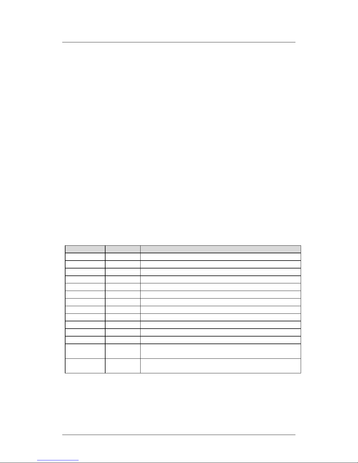
1.3.2 Major Assemblies (Standard or Optional)
“Earlier Units” refers to original production run units. “Later Units”
refer to the Rev A chassis later production run units. See Figure 1-1 and
refer to the notes that follow this table for further information.
PL/10002-1 PL/10002-1 Modulator, 70/140 MHz
PL/11230-1 PL/12113-1 Modulator, L-Band Card
PL/10003-1 PL/10003-1 Demodulator, 70/140 MHz
PL/11571-1 PL/11571-1 Demodulator, L-Band
PL/10005-1 N/A Encoder FEC, Tx LDPC and DVB-S
N/A PL/12148-1 Encoder FEC, Tx LDPC and DVB-S, DVB-DSNG, and DVB-S2
N/A PL/12169-1 Decoder FEC, Rx LDPC and DVB-S, DVB-DSNG, DVB-S2
PL/10012-1 N/A Framing Card with 1.5 ppm reference
PL/11509-1 N/A Optional CDI-70 10/100/1000 Base-T Gigabit Ethernet Data
Interface Module (GBEI) (running Firmware FW11509)
Note 4
Interface Module (GBEI) (running Firmware FW12547)
1–8
Note 4
Page 33

CDM-710/L Broadcast Satellite Modem MN/CDM710.IOM
Introduction Revision 12
Notes:
1) “Earlier” and “Later” units differ as follows:
• “Earlier Units” operate using Firmware FW/12050 (Version 1.1.3
or earlier). “Later Units” operate using Firmware FW/12437
(Version 2.1.1 or later).
• “Earlier Units”are “Tx only” (modulator only) and are not
upgradeable to 16APSK or higher.
• “Earlier Units” do not support redundancy and are not
upgradeable.
2) CDI-40 ASI Data Interface Modules PL/10881-3 (for “Earlier Units”) and
PL/10881-4 (for “Later Units”) have hardware differences that can not be
upgraded through the Firmware Update process (e.g., CReflash). See
para. 1.2.3 for 1:1 and 1:N application information.
3) The CDI-60 HSSI Data Interface Module PL/11582-1 requires Firmware
Version 3.0.1 or later. Generic operation requires Firmware Version 4.1.1
or later.
4) The CDI-70 GBEI Data Interface Module PL/11509-1 can be upgraded to
PL/11509-2 function using the Firmware Update process (e.g., CReflash).
1–9
Page 34

CDM-710/L Broadcast Satellite Modem MN/CDM710.IOM
Introduction Revision 12
1.3.3 Dimensional Envelope
Figure 1-4. Dimensional Envelope
1–10
Page 35

CDM-710/L Broadcast Satellite Modem MN/CDM710.IOM
Introduction Revision 12
1.3.4 Front Panel
Figure 1-5. Front Panel View
The front panel USB 1.1 port is non-functional.
The unit front panel (Figure 1-5) provides the following features:
Item 1 – These handles ease removal and replacement of the chassis into the
user-provided rack enclosure.
Item 2 –Eight (8X) Light-Emitting Diode (LED) indicators convey operational
states as follows:
UNIT STATUS
• Lights GREEN when there are no Unit Faults or Alarms.
• Lights AMBER when there are no Unit Faults, but an Alarm exists.
• Lights RED when a Unit Faults exists (Example: PSU Fault).
Tx STATUS
• Lights GREEN when there are no Tx Traffic Faults or Alarms.
• Lights AMBER when a Tx Traffic Alarm exists.
• Lights RED when a Tx traffic Fault exists.
• Remains OFF when the transmitter is turned OFF (e.g., when the unit is
not configured as a Modulator).
Rx STATUS
• Lights GREEN when there are no Rx Traffic Faults or Alarms.
• Lights AMBER when an Rx Traffic Alarm exists.
1–11
Page 36

CDM-710/L Broadcast Satellite Modem MN/CDM710.IOM
Introduction Revision 12
• Lights RED when an Rx traffic Fault exists.
• Remains OFF when the receiver is turned OFF (e.g., when the unit is not
configured as a Demodulator).
ONLINE
• Lights GREEN when the Unit is On Line, and carrying traffic.
• Remains OFF when the Unit is Off Line (standby) – forced by an externally
connected 1:1 or 1:N Redundancy System).
STORED EVENT
• Lights AMBER when there is a Stored Event in the log.
• Remains OFF when there are no Stored Events.
TRANSMITTER ON
• Lights GREEN when the Transmitter Carrier is ON. This indicator reflects
the actual condition of the transmitter, as opposed to the programmed
condition.
• Remains OFF when the Transmitter carrier is OFF.
REMOTE
• Lights GREEN when the unit is in Remote Communication Mode. Local
monitoring is possible, but there is no local control.
• Remains OFF when the unit is in Local Mode. Remote monitoring is
possible, but no there is no remote control.
TEST MODE
• Lights GREEN when a BERT (Bit Error Rate test) is active.
• Remains OFF when the unit is operating normally.
Item 3 –The keypad comprises six individual keyswitches.
The initially-released chassis featured a membrane switch keypad.
Operation of the individual keys is as follows:
• Use the ENTER key to select a displayed function or to execute a unit
configuration change.
1–12
Page 37

CDM-710/L Broadcast Satellite Modem MN/CDM710.IOM
Introduction Revision 12
• Use the CLEAR key to back out of a selection or to cancel a configuration
change that has not been executed using ENTER. Pressing CLEAR
generally returns the display to the previous selection.
• Use the (LEFT) and (RIGHT) keys to move to the next selection or to
move the cursor functions. At times, they may also used to move from
one section to another.
• Use the (UP) and (DOWN) keys to change configuration data
(numbers). You may also use these keys to move from one section to
another.
The keys for the Rev. A and later chassis have a positive ‘click’ action that
provides tactile feedback. Enter data via the keypad. Data, prompts, and
messages are displayed on the VFD.
Item 4 – The Vacuum Fluorescent Display (VFD) is an active display showing two
lines of 24 characters each. It produces a blue light with adjustable brightness.
Nested menus display all available options and prompt you to carry out a
required action.
1.3.5 Rear Panel
Sect. 4.2 Rear Panel Connectors
Figure 1-6. CDM-710/L Rear Panel View (CDM-710 Shown with Optional CDI-40
ASI and CDI-70 GBEI Data Interface Modules)
External cables are attached to connectors provided on the rear panel of the unit
(Figure 1-6).
1–13
Page 38

CDM-710/L Broadcast Satellite Modem MN/CDM710.IOM
CAUTION
WITH THE CORRECT TYPE AND RATING.
Introduction Revision 12
From left to right:
Item 1 –Power Connection (part of Power Supply module)
• The standard AC unit features a 115/230 VAC Primary Input Power Supply
(IEC-60320 Type C14 three-prong male connector)
• The optional -48V DC unit features a terminal block power interface.
Item 2 – Unit Fusing (part of Power Supply module)
FOR CONTINUED OPERATOR SAFETY, ALWAYS REPLACE THE FUSES
The unit uses two Slo-Blo fuses, one each for line and neutral fusing:
• The standard 115/230 VAC unit retains the T2.00A 5x20 mm fuses
(250VAC time lag) in a press-fit fuse holder.
• The optional -48V DC unit retains the T6.25A 6.3x32 mm fuses in
individual screw-in receptacles.
Item 3 – Unit Ground Lug
Use this #10-32 stud as the command chassis ground.
CAUTION
PROPER GROUNDING PROTECTION IS REQUIRED. You must connect the
equipment to the protective earth connection at all times. Use this
ground stud during installation, configuration, and operation.
Item 4 – ‘J7 | Ext Ref’ Utility Connector
Use this female BNC connector to supply a master reference to the entire
chassis.
Item 5 – ‘J1 | Tx (Transmit)’ IF Connector
CAUTION
THERE MAY BE DC VOLTAGES OF UP TO 48 VOLTS MAXIMUM PRESENT
ON THIS CONNECTOR.
Use this connector for Tx operation:
• CDM-710 (70/140 MHz) – BNC female connector
• CDM-710L (L-Band) – Type ‘N’ female connector
1–14
Page 39

CDM-710/L Broadcast Satellite Modem MN/CDM710.IOM
ON THIS CONNECTOR.
Introduction Revision 12
Item 6 – ‘J4 | ETHERNET’ Ethernet Management Utility Port
Use this 10/100 Base-T Ethernet RJ-45 port for operation of the Ethernet remote
control interfaces.
Item 7 – ‘P1 | ALARMS’ Utility Connector
Use this DB-15M EIA-232 connector to access the Form C Alarms (relay closures).
Item 8 – ‘P2 | Remote’ Serial Management Utility Connector
Use this DB-9M EIA-232/EIA-485 connector for operation of the Serial Interface.
Item 9 – ‘J7 | Rx (Receive)’ IF Connector
CAUTION
THERE MAY BE DC VOLTAGES OF UP TO 48 VOLTS MAXIMUM PRESENT
Use this connector for Rx operation:
• CDM-710 (70/140 MHz) – BNC female connector
• CDM-710L (L-Band) – Type ‘N’ female connector
Item 10 – ‘J6 | Async Channel’ Utility Connector (NOT USED)
1) Asynchronous Engineering Channel operation is not implemented in
the CDM-710/L; this DB-9F connection is therefore non-operational.
2) This connection exists on Rev. A and later chassis only. The original
production unit provided an RJ-45 connector, labeled ‘J6 | SerDes’. It
served as a private communications link and was not intended for
customer use.
Item 11 – Optional Data Interface Module Slot 1
See Sect. 1.3.5.1 for further details.
Item 12 – Optional Data Interface Module Slot 2
See Sect. 1.3.5.1 for further details.
1–15
Page 40
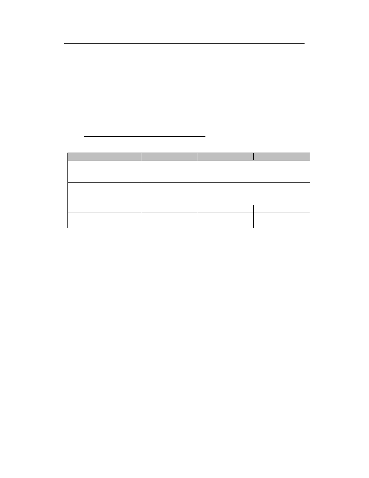
CDM-710/L Broadcast Satellite Modem MN/CDM710.IOM
INTERFACE (GBEI)
PL/10881-3
PL/10881-4
more information
Introduction Revision 12
1.3.5.1 Optional Data Interface Modules
• Appendix B. CDI-40 ASI DATA INTERFACE
• Appendix C. CDI-60 HSSI DATA INTERFACE
• Appendix D. CDI-70 10/100/1000 BASE-T GIGABIT ETHERNET
The optional data interface modules are installed or removed from the chassis
rear panel Interface Slots 1 and 2. See Table 1-1 for the allowable combination of
data interfaces and the data interfaces that are supported for redundancy. In all
cases, only one data interface is active at a time
Table 1-1. Data Interface Information
Interface CEFD P/N 1:1 Capability 1:N Capability
.
CDI-40 ASI
(Earlier Units)
CDI-40 ASI
(Later Units)
CDI-60 HSSI PL/11582-1 OK Tx, Rx or Duplex OK Tx, Rx or Duplex
CDI-70 GBEI
See Appendix B for
more information
See Appendix B for
PL/11509-2 or
PL/11509-3
See Note 1
See Note 2
OK Tx, Rx or Duplex OK Tx, Rx or Duplex
Notes:
1) The original (“Earlier Units”) CDI-40 supports Tx, Rx, or Duplex operation
in non-redundant applications, or Tx-only in 1:1 applications. For 1:N
applications, the module supports Tx, Rx, or Duplex operation, where
the CDI-40 ‘Rx | J2’ and ‘1:1 Rx | J3’ outputs provide the standard ASI
level.
2) The current (“Later Units”) CDI-40 supports Tx, Rx, or Duplex operation in
1:1 or non-redundant applications, where the CDI-40 ‘Rx | J2’ output is
the standard ASI level, and the ‘1:1 Rx | J3’ output is higher so the
standard level is delivered after a 3 dB combiner. For 1:N applications,
the CDI-40 supports Tx, Rx, or Duplex operation, excluding the CDI-40 ‘1:1
Rx | J3’ output.
1–16
Page 41
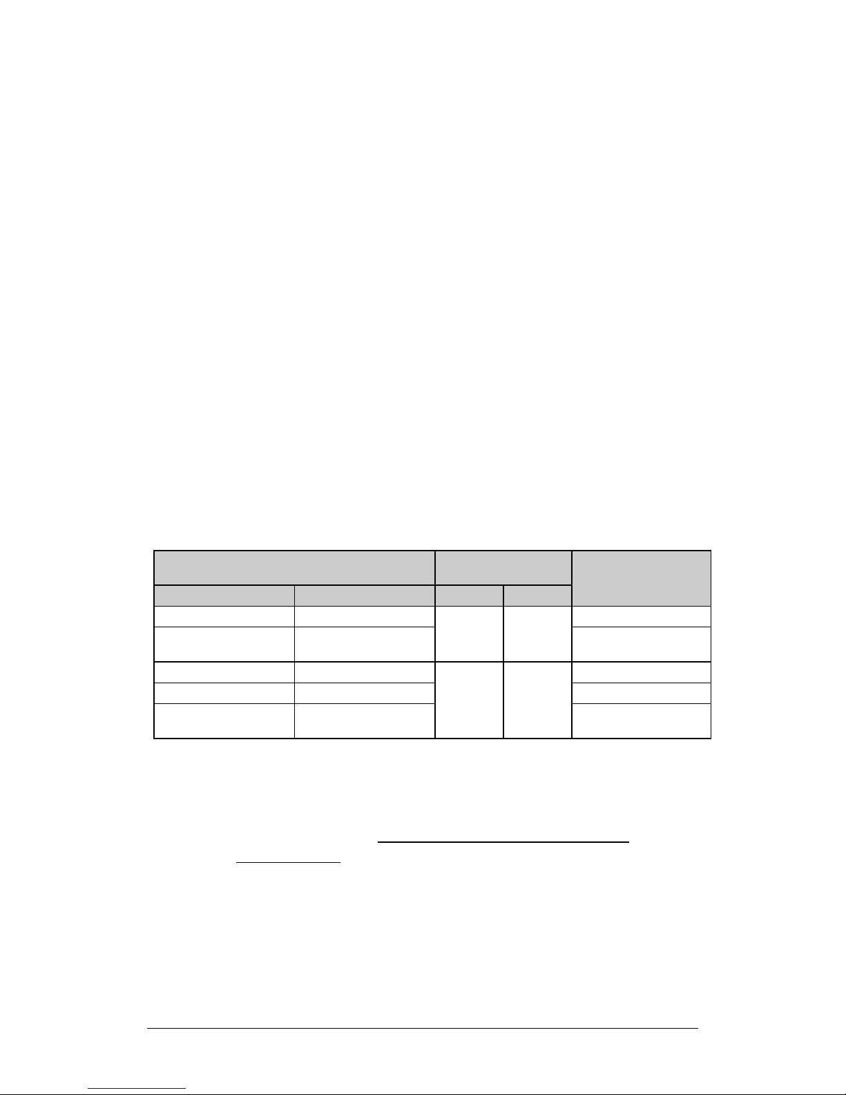
CDM-710/L Broadcast Satellite Modem MN/CDM710.IOM
modulator card.
simultaneously.
Introduction Revision 12
1.3.5.1.1 Data Interface Support in 1:1 or 1:N Redundancy
Configurations
1:1 Redundancy with the CRS-180 (70/140 MHz) or CRS-170A (L-Band)
Redundancy Switch: The “CDM-710/L Unit Configuration” column in Table 1-2
shows the CDM-710/L data interface combinations that are supported by the
CRS-180 or CRS-170A 1:1 Redundancy Switches. You must first select a 1:1 switch
based on the operating frequency. You must then choose your Slot 1 and Slot 2
modules. See the CRS-170A or CRS-180 1:1 Redundancy Switch datasheet and
Installation and Operation manuals for further information.
When you use a CDM-710/L as a Tx Only unit in 1:1 Redundancy, you
must remove the demodulator card. Similarly, when you use a
CDM-710/L as an Rx Only unit in 1:1 Redundancy, you must remove the
1:N Redundancy with the CRS-300: The CRS-300 was originally designed for
operation with the CDM-600. It has since been adapted for use with a number of
other modems. It is capable of supporting interfaces up to the point where there
are no more paths left to route traffic; this is the reason why the CRS-300
supports a limited set of the interface combinations supported by the
CDM-710/L.
Table 1-2. Allowable Unit/Switch Data Interface Configurations
CDM-710/L Unit Configuration
Interface Slot 1 Interface Slot 2 TMI Card RMI Card
CDI-40 ASI None
CDI-40 ASI CDI-70 GBEI
CDI-60 HSSI None
None CDI-70 GBEI -
CDI-60 HSSI CDI-70 GBEI
1:N CRS-300
Configuration
CRS-325 CRS-306
CRS-336 CRS-306
Can be used as a
Redundant Unit
Can be used as a
Redundant Unit
1) The Redundant Unit must have the same interface cards in each
slot as any of the Traffic Units.
2) Your Traffic Unit must have the same interface cards installed in
each slot identically as any other Traffic Units. You must otherwise
install a blank panel. Interface Slots 1 and 2 are not active
Notes
-
-
1–17
Page 42

CDM-710/L Broadcast Satellite Modem MN/CDM710.IOM
Introduction Revision 12
Notes:
1–18
Page 43

Chapter 2. SPECIFICATIONS
(L-Band) Broadcast Satellite Modem unless noted.
2.1 Physical and Environmental Specifications
All information is typical for the CDM-710 (70/140 MHz) or CDM710L
2.1.1 Regulatory Compliance
• “CE” as follows:
o EN 30489-1
o EN 55022 Class B (Emissions)
o EN 55024 (Immunity)
o EN 60950 (Safety)
• FCC Part 15 Subpart B.
• RoHS-Compliant.
2.1.2 Physical Specifications
• Dimensions: 1.72 H x 19.00 W x 18.65 D inches
(43.7 mm H x 482.6 mm W x 473.7 mm D)
• Weight: 15lbs (6.8 kg)
2.1.3 Modular Design
Simplex or Duplex
2–1
Page 44

CDM-710/L Broadcast Satellite Modem MN/CDM710.IOM
Specifications Revision 12
2.1.4 Temperature Range
• Operating: 32° to 122 F° (0° to 50° C)
• Storage: -4° to 158 F° (-20° to 70° C)
2.1.5 Humidity (Non-condensing)
• Operating: 95% maximum
• Storage: 99% maximum
2.1.6 Front Panel Features
2.1.6.1 LED Monitoring
(8X) Status LEDs:
• UNIT STATUS (Green/Amber/Red)
• Tx STATUS (Green/Amber/Red)
• Rx STATUS (Green/Amber/Red)
• ONLINE (Green)
• STORED EVENT (Amber)
• TRANSMITTER ON (Green)
• REMOTE (Green)
• TEST MODE (Green)
2.1.6.2 Keypad
Six Keys: (LEFT), (RIGHT), (UP), (DOWN), ENTER, CLEAR
2.1.6.3 Vacuum Fluorescent Display (VFD)
2 lines, 24 characters per line.
2–2
Page 45

CDM-710/L Broadcast Satellite Modem MN/CDM710.IOM
Specifications Revision 12
2.1.7 Rear Panel Features
2.1.7.1 Chassis AC Power Cord Retainer
Standard
2.1.7.2 Chassis Power Supply Input
• AC: 100-240VAC 50/60Hz, auto-ranging. IEC-60320 Type C14 (male)
three-prong connector, for connection with an IEC-60320 Type C13
(female) three-prong plug.
• DC: -48V DC via terminal block power interface.
2.1.7.3 Chassis Power Consumption
<75W, 55W typical
2.1.7.4 Chassis Fusing
• AC: T2.00A 5mm x 20 mm 250VAC time lag.
• DC: T6.25A 6.3 mm x 32 mm (3AG), 250VAC time lag.
2.1.7.5 IF Connectors
CDM-710:
(2X) BNC female connectors for 70/140 MHz (52 to 88 MHz or 104 to 176 MHz in
100Hz steps), impedance programmable @ 75Ω or 50Ω, 18 dB minimum return
loss: ‘J1 |Tx’ and ‘J2 | Rx’
CDM-710L:
(2X) 50Ω Type ‘N’ female connectors for L-Band (950 to 2150 MHz in 100 Hz
steps @ 15 dB minimum return loss: ‘J1 |Tx’ and ‘J2 | Rx’
2–3
Page 46

CDM-710/L Broadcast Satellite Modem MN/CDM710.IOM
Specifications Revision 12
2.1.7.6 Ethernet Connector
(1X) 10/100 BaseT Ethernet RJ-45 ‘J4 | Ethernet’ Ethernet Management Utility
Port for operation of the Ethernet remote control interfaces (SNMP, Telnet,
HTTP).
2.1.7.7 Serial Connectors
(1X) DB-15M (D-Subminiature) ‘P1 | Alarms’ Utility Connector to access the Form
C Alarms (relay closures).
(1X) DB-9M (D-Subminiature) ‘P2 | Remote’ EIA-232/EIA-485 (2-Wire/4-Wire)
connector for operation of the Serial Interface.
(1X) DB-9F (D-Subminiature) ‘J6 | Async’ connector (NOT USED).
2.1.7.8 Utility Connector
(1X) Type BNC female ‘J7 | Ext Ref’ connector, used to supply a master reference
to the entire chassis.
2–4
Page 47

CDM-710/L Broadcast Satellite Modem MN/CDM710.IOM
Specifications Revision 12
2.2 Operational Specifications
All information is typical for the CDM-710 or CDM710L unless noted.
2.2.1 Unit Configuration
Non-volatile for 1-year minimum and returns upon power up.
2.2.2 Symbol Rates
• DVB-S: 1 to 45 Msps
• DVB-S2: 1 to 45 Msps (QPSK, 8PSK); 35 Msps (16APSK); 28 Msps (32APSK)
• DVB-DSNG: 1 to 45 Msps
2.2.3 Data Rate
Corresponds to Symbol Rate. See Sect. 2.3.
2.2.4 Symbol Rate/Data Rate
See Sect. 2.2.20 Modulator (Transmit) Specifications/Sect. 2.2.21 Demodulator
(Receive) Specifications.
2.2.5 Forward Error Correction (FEC) Types
• DVB-S per EN 301 421
QPSK 1/2, 2/3, 3/4, 5/6, 7/8 Convolutional + Reed Solomon
• DVB-S2 per EN 302 307
QPSK: 1/2, 3/5, 2/3, 3/4, 4/5, 5/6, 8/9, 9/10 LDPC + BCH
8PSK: 3/5, 2/3, 3/4, 5/6, 8/9, 9/10 LDPC + BCH
16APSK: 2/3, 3/4, 4/5, 5/6, 8/9, 9/10 LDPC + BCH
32APSK: 3/4, 4/5, 5/6, 8/9, 9/10
• DVB-DSNG per EN 301 210
8PSK: 2/3, 5/6, 8/9 Convolutional + Reed Solomon
16QAM: 3/4, 7/8 Convolutional + Reed Solomon
2–5
Page 48

CDM-710/L Broadcast Satellite Modem MN/CDM710.IOM
Specifications Revision 12
2.2.6 Operating Modes
Only Constant Coding and Modulation (CCM) is supported.
2.2.7 Transport Streams
Only Single Transport Stream is supported.
2.2.8 Physical Layer (PL) Scrambling
User specified value (one) of n = 0 to 262,141, per EN 302 307.
2.2.9 Pilot Insertion
Selectable ON or OFF.
2.2.10 1:1 Redundancy
Built-in controller for operation with an optional Comtech EF Data 1:1
Redundancy Switch:
• The CDM-710 uses the CRS-180 switch for 70/140 MHz operation.
• The CDM-710L uses the CRS-170A switch for L-Band operation.
2.2.11 1:N Redundancy
1:N redundancy is supported by the Comtech EF Data CRS-300 1:10 Redundancy
Switch.
2.2.12 Fault Handling
Form ‘C’ via the DB-15M ‘P1 | Alarms’ rear panel connector– see Chapter 5.
REAR PANEL CONNECTIONS for pinout information.
2–6
Page 49

CDM-710/L Broadcast Satellite Modem MN/CDM710.IOM
Specifications Revision 12
2.2.13 External Tx Carrier Off
TTL Low Signal - path bypasses microprocessor (DB-15M ‘P1 | Alarms’ rear panel
connector– see Chapter 5. REAR PANEL CONNECTIONS for pinout information).
2.2.14 Frequency Reference (Selectable)
• Internal Reference: 10 MHz for data and IF, stability ± 1.5 ppm
• External Reference: 1, 2, 5, 10 or 20 MHz for IF, internally phase locked.
Input is 50Ω or 75Ω compatible with 0.5 to 4.0 V
sine or square wave.
p-p
Requires high stability source.
• External Clock: For data interfaces only, not IF. Clock Input depends upon
the installed data interface module(s).
2.2.15 Test Functions
• Data Test Patterns: 2047 and 2
23-1
compatible with BERT on Tx data
tributaries on applicable data interfaces
• CW generates a narrow carrier at the programmed frequency at the
programmed power level. Used in testing.
• SSB Carrier provides desired sideband, suppressed carrier, and
suppressed sideband.
• Loopback Modes:
o Modulator to Demodulator
o I/O Loopback where applicable
o Digital Loopback where applicable
2.2.16 Monitor Functions
• LED Status Indicators are provided on the front panel (see Sect. 2.1.6.1).
• Fault logs providing fault type and time/date stamp are viewable on the
VFD.
• Receive Signal Level is reported within ± 5 dB (typical).
• E
• E
is reported within ± 0.5 dB (typical).
S/N0
is reported within ± 0.5 dB (typical).
b/N0
2–7
Page 50
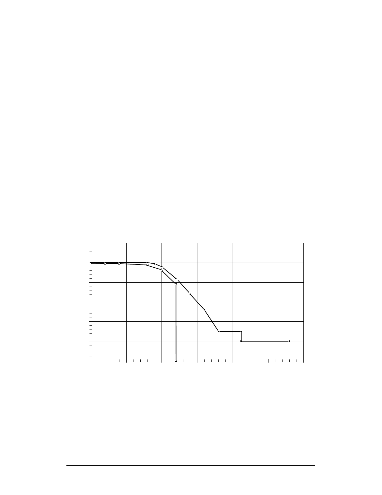
CDM-710/L Broadcast Satellite Modem MN/CDM710.IOM
Relative power (dB)
-50
-40
-30
-20
-10
0
10
0 0,5 1 1,5 2 2,5 3
ABC
D
E
F
G
H
J
K
L
M
N
P
Q
S
I
f/f
N
Specifications Revision 12
2.2.17 Remote M&C Operations
Using a Windows-based user PC to access the Ethernet or serial interfaces:
• Ethernet-based M&C – See Chapter 8. ETHERNET INTERFACE OPERATION.
Use the RJ-45 ‘J4 | ETHERNET’ port for Ethernet-based monitor and
control:
o Telnet – Ethernet issuance of remote command and queries using
a user-supplied terminal emulator.
o SNMP –Simple Network Management Protocol (SNMPv1 and
SNMPv2c) operation using the CDM-710 SNMP agent.
o HTTP – Use of the HTTP Interface with a user-supplied web
browser.
• Serial-based M&C – See Chapter 9. SERIAL INTERFACE OPERATION. Use
the DB-9M ‘P2 | Remote’ EIA-232/EIA-485 (2-Wire/4-Wire) connector for
issuance of remote command and queries.
2.2.18 Spectral Mask
20%, 25%, or 35% per DVB-S, DVB-S2, DVB-DSNG. See Figure 2-1, Table 2-1.
Figure 2-1. Spectral Mask
2–8
Page 51
CDM-710/L Broadcast Satellite Modem MN/CDM710.IOM
A
0,0 fN
0,0 fN
0,0 fN
+0,25
+0,07/fN
B
0,0 fN
0,0 fN
0,0 fN
-0,25
-0,07/fN
C
0,2 fN
0,2 fN
0,2 fN
+0,25
+0,07/fN
G
0,8 fN
0,86fN
0,89 fN
+0,15
+0,07/fN
H
0,8 fN
0,86 fN
0,89 fN
-1,10
-0,07/fN
I
0,9 fN
0,93 fN
0,94 fN
-0,50
+0,07/fN
J
1,0 fN
1,0 fN
1,0 fN
-2,00
+0,07/fN
K
1,0 fN
1,0 fN
1,0 fN
-4,00
-0,07/fN
L
1,2 fN
1,13 fN
1,11 fN
-8,00
-
M
1,2 fN
1,13 fN
1,11 fN
-11,00
- N 1,8 fN
1,60 fN
1,5 fN
-35,00
-
Specifications Revision 12
Table 2-1. Definition of Points For Spectral Mask
Point
D 0,2 fN 0,2 fN 0,2 fN -0,40 -0,07/fN
E 0,4 fN 0,4 fN 0,4 fN +0,25 +0,07/fN
F 0,4 fN 0,4 fN 0,4 fN -0,40 -0,07/fN
P 1,4 fN 1,30 fN 1,23 fN -16,00 -
Q 1,6 fN 1,45 fN 1,4 fN -24,00 -
S 2,12 fN 1,83 fN 1,7 fN -40,00 -
Frequency
for α=0,35
Frequency
for α=0,25
Frequency
for α=0,20
Relative power
(dB)
Group delay
2.2.19 Firmware Update
CReflash utility via 10/100 BaseT Ethernet RJ-45 ‘J4 | Ethernet’ Utility Port.
2–9
Page 52

CDM-710/L Broadcast Satellite Modem MN/CDM710.IOM
Specifications Revision 12
2.2.20 Modulator (Transmit) Specifications
2.2.20.1 Frequency Range
Bandwidth of transmitted spectrum is within IF frequency range:
• CDM-710: 52 to 88 MHz or 104 to 176 MHz in 100Hz steps.
• CDM-710L: 950 to 2000 MHz in 100Hz steps.
2.2.20.2 Impedance
• CDM-710: 75Ω or 50Ω, programmable.
• CDM-710L: 50Ω
2.2.20.3 ‘J1 | Tx’ Connector Type
• CDM-710: BNC female
• CDM-710L: Type ‘N’ female.
2.2.20.4 Return Loss
• CDM-710: 18 dB
• CDM-710L: 15 dB
2.2.20.5 Output Power
Carrier is not interrupted when changing between output power levels or
removing data connections:
• CDM-710: 0 to -20 dBm in 0.1 dB steps.
• CDM-710L: -5 to -25 dBm in 0.1 dB steps.
2.2.20.6 Output Power Accuracy
±0.5 dB at 25°C
2–10
Page 53

CDM-710/L Broadcast Satellite Modem MN/CDM710.IOM
Specifications Revision 12
2.2.20.7 Output Power Stability
Within ±0.5 dB of 25°C value over all specified environments.
2.2.20.8 Carrier Mute
55 dB below main carrier output.
2.2.20.9 Carrier Null
35 dB below an unmodulated carrier.
2.2.20.10 Harmonics and Spurious
-55 dBc/4 kHz over operating frequency range (excludes spectral mask area) and
is with a modulated carrier
• CDM-710: -55 dBc/4 kHz 10 to 52 MHz, 176 to 250 MHz
• CDM-710L: -55 dBc/4 kHz 250 to 950 MHz, 1950 to 2500 MHz
2.2.20.11 Integrated Phase Noise
Continuous component <1° RMS double-sided, 100 Hz to 10 MHz.
2.2.20.12 Spectral Inversion
Normal or Inverted.
2.2.20.13 Quadrature Phase Error
< 2°
2.2.20.14 Quadrature Amplitude Imbalance
0.2 dB maximum.
2–11
Page 54

CDM-710/L Broadcast Satellite Modem MN/CDM710.IOM
Specifications Revision 12
2.2.20.15 Combined Amplitude Imbalance and Quadrature
Phase Error
Single sideband test with suppressed sideband 35 dB minimum below
unmodulated carrier.
2.2.21 Demodulator (Receive) Specifications
2.2.21.1 Frequency Range
• CDM-710: 52 to 88 MHz or 104 to 176 MHz in 100Hz steps.
• CDM-710L: 950 to 2150 MHz in 100Hz steps.
2.2.21.2 ‘J2 | Rx’ Connector Type/Impedance
• CDM-710: BNC female/50Ω (standard) or 75Ω (optional).
• CDM-710L: Type ‘N’ female/50Ω
2.2.21.3 Return Loss
• CDM-710: 18 dB
• CDM-710L: 10 dB
2.2.21.4 Input Power, Minimum
-58 + 10
• CDM-710: -58 dBm at 1 Msps, -41.5 dBm at 45 Msps. See Figure 2-2.
• CDM-710L: -58 dBm at 1 Msps, -41.5 dBm at 45 Msps
(Symbol Rate in MHz) dBm:
log
2–12
Page 55
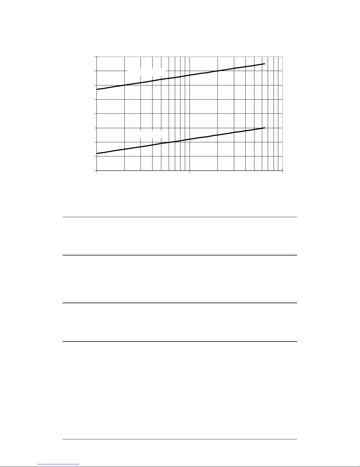
CDM-710/L Broadcast Satellite Modem MN/CDM710.IOM
-70
-60
-50
-40
-30
-20
-10
0
10
1 10 100
Symbol Rate (Msps)
Carrier Input Level (dBm)
M ax imum Level
M inimum Level
Carrier Input Level (vs) S ymbol Rate
Specifications Revision 12
Figure 2-2. Demodulator Input Level
2.2.21.5 AGC (Automatic Gain Control) Range
45 dB above minimum.
2.2.21.6 Maximum Composite Level
• CDM-710: +20 dBc composite to desired up to +10 dBm
• CDM-710L: +30 dBc composite to desired up to +10 dBm
2.2.21.7 Acquisition Range
±100 kHz programmable in 1 kHz steps.
2.2.21.8 Acquisition Time
Typical <10 seconds (DVB-S2 Pilots ON).
2–13
Page 56

CDM-710/L Broadcast Satellite Modem MN/CDM710.IOM
Specifications Revision 12
2.2.21.9 Adaptive Equalizer
Up to 3 dB tilt.
2.2.21.10 BER Performance
See Table 2-2 through Table 2-5.
2.2.21.11 IQ Test Po i nt
Accessible from the rear panel DB-15M ‘P1 | ALARMS’ connector.
2–14
Page 57
CDM-710/L Broadcast Satellite Modem MN/CDM710.IOM
64,800 bits
16,200 bits
1/4
0.490243
0.365324
-1.85
1.25
1/3
0.656448
0.629060
-0.74
1.09
2/5
0.789412
0.760928
0.20
1.23
1/2
0.988858
0.848840
1.50
1.55
3/5
1.188304
1.156532
2.73
1.98
3/4
2.228124
2.118761
8.61
5.13
5/6
2.478562
2.381056
10.15
6.21
8/9
2.646012
2.577778
11.49
7.26
4/5
3.165623
2.983575
12.03
7.03
5/6
3.300184
3.157488
12.61
7.42
8/9
3.523143
3.418357
13.89
8.42
9/10
3.567342
N/A
14.13
8.61
3/4
3.703295
3.493093
13.73
8.04
4/5
3.951571
3.709309
14.64
8.67
5/6
4.119540
3.925526
15.28
9.13
8/9
4.397854
4.249850
16.69
10.26
Specifications Revision 12
Table 2-2. Eb/No Performance at Quasi Error Free PER = 10-7 with AWGN for
DVB-S2 Operations
Modulation
DVB-S2
QPSK
(Note 1)
8-PSK
(FECFRAME = 64,800 or 16,200 Bits and no Pilot)
Code
Rate
2/3 1.322253 1.288400 3.60 2.39
3/4 1.487473 1.420269 4.53 2.81
4/5 1.587196 1.508181 5.18 3.17
5/6 1.654663 1.596093 5.68 3.49
8/9 1.766451 1.727961 6.70 4.23
9/10 1.788612 N/A 6.92 4.39
3/5 1.779991 1.725319 6.20 3.70
2/3 1.980636 1.922040 7.32 4.35
9/10 2.679207 N/A 11.78 7.50
2/3 2.637201 2.548792 9.97 5.76
3/4 2.966728 2.809662 11.21 6.49
Spectral Efficiency
FECFrame =
FECFrame =
Specified Es/No (dB)
See Notes
Eb/No (dB)
See Notes
16-APSK
32-APSK
9/10 4.453027 N/A 17.05 10.56
Notes:
1) QPSK 1/4, 1/3, and 2/5 are provided for reference only.
2) Eb/No = Es/No – 10
3) BER ≈ 10
-9
at PER = 10-7
(Spectral Efficiency).
log
4) Performance with FECFRAME = 16,200 Bits and no pilot is typically 0.2 to
0.3 dB higher.
2–15
Page 58
CDM-710/L Broadcast Satellite Modem MN/CDM710.IOM
10-6
3.7
4.4
5.0
5.6
5.9
10-8
6.6
8.3
9.1
10
6.9
8.8
9.4
10-4
8.1
10.0
10-6
8.3
10.2
Specifications Revision 12
Table 2-3. Eb/No Performance for DVB-S QPSK Operations
BER
Eb/No (dB)
1/2 2/3 3/4 5/6 7/8
10-8 4.0 4.7 5.3 5.9 6.3
-11
10
4.5 5.1 5.8 6.4 6.9
Table 2-4. Eb/No Performance for DSNG 8PSK Operations
Eb/No (dB)
BER
2/3 5/6 8/9
10-4 6.0 7.5 8.5
10-6 6.3 7.9 8.8
-10
Table 2-5. Eb/No Performance for DSNG 16QAM Operations
Eb/No (dB)
BER
3/4 7/8
10-8 8.6 10.4
-10
10
8.9 10.6
2.3 Data Rate Ranges
For the Symbol Rate and Data Rate Ranges for DVB-S, DVB-S2 and DVB-DSNG,
there is some roundoff in the last digit of the values as listed. Table 2-6 is for the
Standard FEC frame, and Table 2-7 is for the Short Frame. QPSK 1/4, 1/3, and 2/5
data is provided for reference only. The tables are based on a 188-byte transport
stream packet. When a 204-byte frame size is selected, the data rate increases
by 204/188.
DVB recommends turning the Pilot ON for 8PSK and higher modulation orders,
particularly when phase noise is present. For 8PSK 1/2, 16APSK 2/3 and 3/4, and
32APSK 3/4: To assist carrier recovery, these modes may need Pilot ON for low
C/N operation.
2–16
Page 59
CDM-710/L Broadcast Satellite Modem MN/CDM710.IOM
Symbol Rate
Data Rate (M bps)
Data Rate (M bps)
Min
Max
Min
Max
Min
Max
DVB-S2 - Standard FEC Frame = 64,800 Bits
LDPC+BCH
1/4
0.490243
0.490243
22.060942
0.478577
0.478577
21.535965
1/3
0.656448
0.656448
29.540166
0.640827
0.640827
28.837209
3/5
1.188304
1.188304
53.473684
1.160026
1.160026
52.201190
2/3
1.322253
1.322253
59.501385
1.290788
1.290788
58.085452
3/4
1.487473
1.487473
66.936288
1.452076
1.452076
65.343429
4/5
1.587196
1.587196
71.423823
1.549426
1.549426
69.724175
5/6
1.654663
1.654663
74.459834
1.615288
1.615288
72.687939
8/9
1.766451
1.766451
79.490305
1.724416
1.724416
77.598702
9/10
1.788612
1.788612
80.487535
1.746049
1.746049
78.572201
LDPC+BCH
3/5
1.779991
1.779991
80.099585
1.739569
1.739569
78.280616
2/3
1.980636
1.980636
89.128631
1.935658
1.935658
87.104623
3/4
2.228124
2.228124
100.265560
2.177525
2.177525
97.988646
5/6
2.478562
2.478562
111.535270
2.422276
2.422276
109.002433
8/9
2.646012
2.646012
119.070539
2.585924
2.585924
116.366586
LDPC+BCH
3/4
2.966728
2.966728
103.835482
2.896320
2.896320
101.371209
4/5
3.165623
3.165623
110.796808
3.090495
3.090495
108.167326
5/6
3.300184
3.300184
115.506446
3.221863
3.221863
112.765192
8/9
3.523143
3.523143
123.310006
3.439530
3.439530
120.383555
9/10
3.567342
3.567342
124.856967
3.482680
3.482680
121.893803
LDPC+BCH
3/4
3.703295
3.703295
103.692261
3.623332
3.623332
101.453291
4/5
3.951571
3.951571
110.643985
3.866247
3.866247
108.254911
5/6
4.119540
4.119540
115.347126
4.030589
4.030589
112.856500
8/9
4.397854
4.397854
123.139923
4.302894
4.302894
120.481032
9/10
4.453027
4.453027
124.684751
4.356875
4.356875
121.992503
DVB-S & DVB-DSNG FEC Frame Do es Not Apply
1/2
0.921569
0.921569
41.470588 - -
-
5/6
1.535948
1.535948
69.117647 - - - 7/8
1.612745
1.612745
72.573529 - -
-
2/3
1.843137
1.843137
82.941176 - -
-
5/6
2.303922
2.303922
103.676471 - - - 8/9
2.457516
2.457516
110.588235 - -
-
3/4
2.764706
2.764706
124.411765 - - - 7/8
3.225490
3.225490
145.147059 - -
-
Specifications Revision 12
Table 2-6. Data Rate Range: Standard FEC Frame (188 Byte Format)
Modulation FEC Code
QPSK
8PSK
16APSK
Inner
Code
(Msps)
Rate
2/5 0.789412 0.789412 35.523546 0.770627 0.770627 34.678204
1/2 0.988858 0.988858 44.498615 0.965327 0.965327 43.439697
1 45
1 45
9/10 2.679207 2.679207 120.564315 2.618365 2.618365 117.826440
2/3
1 35
Spectral
Efficiency
Pilot OFF
2.637201 2.637201 92.302026 2.574613 2.574613 90.111471
Pilot OFF
Spectral
Efficiency
Pilot ON
Pilot ON
32APSK
QPSK Conv+RS
8-PSK Conv+RS
16-QAM Conv+RS
1 28
2/3 1.228758 1.228758 55.294118 - - -
1 45
3/4 1.382353 1.382353 62.205882 - - -
1 45
1 45
2–17
Page 60
CDM-710/L Broadcast Satellite Modem MN/CDM710.IOM
Symbol Rate
(Msps)
Data Rate (M bps)
Pilot OFF
Data Rate (M bps)
Pilot ON
DVB-S2 - Short F EC Frame = 16,2 00 Bits
1/4
0.365324
0.365324
16.439560
0.357467
0.357467
16.086022
1/3
0.629060
0.629060
28.307692
0.615532
0.615532
27.698925
2/5
0.760928
0.760928
34.241758
0.744564
0.744564
33.505376
1/2
0.848840
0.848840
38.197802
0.830585
0.830585
37.376344
3/5
1.156532
1.156532
52.043956
1.131661
1.131661
50.924731
2/3
1.288400
1.288400
57.978022
1.260693
1.260693
56.731183
3/4
1.420269
1.420269
63.912088
1.389725
1.389725
62.537634
4/5
1.508181
1.508181
67.868132
1.475747
1.475747
66.408602
5/6
1.596093
1.596093
71.824176
1.561768
1.561768
70.279570
8/9
1.727961
1.727961
77.758242
1.690800
1.690800
76.086022
9/10
N/A
N/A
N/A
N/A
N/A
N/A
2/3
1.922040
1.922040
86.491803
1.884959
1.884959
84.823151
3/4
2.118761
2.118761
95.344262
2.077885
2.077885
93.504823
8/9
2.577778
2.577778
116.000000
2.528046
2.528046
113.762058
9/10
N/A
N/A
N/A
N/A
N/A
N/A
3/4
2.809662
2.809662
98.338164
2.761633
2.761633
96.657170
4/5
2.983575
2.983575
104.425121
2.932574
2.932574
102.640076
8/9
3.418357
3.418357
119.642512
3.359924
3.359924
117.597341
9/10
N/A
N/A
N/A
N/A
N/A
N/A
3/4
3.493093
3.493093
97.806607
3.419165
3.419165
95.736626
4/5
3.709309
3.709309
103.860661
3.630805
3.630805
101.662551
5/6
3.925526
3.925526
109.914715
3.842446
3.842446
107.588477
8/9
4.249850
4.249850
118.995796
4.159906
4.159906
116.477366
9/10
N/A
N/A
N/A
N/A
N/A
N/A
Specifications Revision 12
Table 2-7. Data Rate Range: Short Frame (188 Byte Format)
Modulation FEC Code
QPSK LDPC+BCH
8PSK LDPC+BCH
16APSK LDPC+BCH
Inner
Code
Rate
Min Max Min Max Min Max
1 45
3/5
1 45
5/6 2.381056 2.381056 107.147541 2.335120 2.335120 105.080386
2/3
1 35
5/6 3.157488 3.157488 110.512077 3.103514 3.103514 108.622982
Spectral
Efficiency
Pilot OFF
1.725319 1.725319 77.639344 1.692033 1.692033 76.141479
2.548792 2.548792 89.207729 2.505223 2.505223 87.682811
Spectral
Efficiency Pilot
ON
32APSK LDPC+BCH
1 28
2–18
Page 61

Chapter 3. INSTALLATION
3.1 Unpack and Inspect the Shipment
Figure 3-1. Unpack and Inspect the Shipment
The CDM-710/L Broadcast Satellite Modem, its optional Installation and
Operation Manual (available online at http://www.comtechefdata.com), and its
power cord were packaged and shipped in a reusable cardboard carton
containing protective foam spacing (Figure 3-1).
3–1
Page 62

CDM-710/L Broadcast Satellite Modem MN/CDM710.IOM
CAUTION
PRECAUTIONARY PROCEDURES WHEN HANDLING THE EQUIPMENT.
Inspect the shipment. Do these steps:
4. Read the manual.
Installation Revision 12
THIS EQUIPMENT CONTAINS PARTS AND ASSEMBLIES SENSITIVE TO
DAMAGE BY ELECTROSTATIC DISCHARGE (ESD). USE ESD
1. Keep all shipping materials.
2. Check the packing list to make sure the shipment is complete.
3. Inspect the equipment for damage. If damage exists,
immediately contact the carrier and Comtech EF Data to submit
a damage report.
3–2
Page 63

CDM-710/L Broadcast Satellite Modem MN/CDM710.IOM
Installation Revision 12
3.2 Install the Modem into a Rack Enclosure
Install the modem in its assigned position in a rack enclosure (Figure 3-2). You must
install the rack in a location with a controlled environment. Failure to obey this
requirement can cause damage to the equipment, and denial of subsequent
warranty claims. You may use:
• A standard rack-mounted shelf;
• User-supplied screws to secure the front panel to the rack enclosure threaded
front mounting rails;
• Comtech EF Data’s optional KT/6228-2 (4”) or KT/6228-3 (10”) Rear Support
Brackets Kit (
• Comtech EF Data’s optional
(Figure 3-4).
• For information about custom rack enclosures, contact Comtech EF Data
Product Support.
CAUTION
CORRECT GROUNDING PROTECTION IS REQUIRED – Connect the ground
stud, located on the rear panel of the modem, to a power system that
has separate ground, line and neutral conductors. Do not operate the
modem without a direct connection to ground.
The rack must be connected to a suitable earthing connection at all
times. You must connect the rack ground bar to a suitable earthing
demarcation point.
CORRECT AIR VENTILATION IS REQUIRED – Air flow must not be
impeded. Make sure there is proper air ventilation. Do not block the top
of the rack or the presence of a rack blower. The air temperature inside
the rack must never exceed 50°C (122°F).
Figure 3-3).
FP/SL0006 Bearingless 26” Rack Slide Set
If there is any doubt, contact Comtech EF Data Product Support during
normal business hours.
3–3
Page 64
CDM-710/L Broadcast Satellite Modem MN/CDM710.IOM
2
CDM-710/L chassis
3
Standard Rack Shelving
4
Rack Enclosure Threaded Front Rail (typical)
Installation Revision 12
Feature Description
1 Custom Rack Enclosure
5 Modem Front Panel
6 User-supplied Screws
Figure 3-2. Install the Modem into a Rack Enclosure
3–4
Page 65
CDM-710/L Broadcast Satellite Modem MN/CDM710.IOM
Kit / Quantity
1 2 2
HW/10-32SHLDR
Shoulder Screw, #10
4 2 2
HW/10-32HEXNUT
Hex Nut, #10
Bracket
(4”)
Installation Revision 12
3.2.1 Install the Optional Rear Support Brackets Kit
Feature Description
1 Back of modem
2 Rack Enclosure Threaded Rear Mounting Rail (typical)
Item
CEFD P/N Description
KT/6228-2 KT/6228-3
2 4 4 HW/10-32FLT Flat Washer, #10
3 2 2 HW/10-32SPLIT Lock Washer, #10
5 4 4 HW/10-32x1/2RK
2 – FP/6138-2
Bolt, #10, Rear Support
Bracket, Rear Support
6
– 2 FP/6138-3
Figure 3-3. Install the Optional Rear-Mounting Support Brackets Kit
Bracket, Rear Support
(10”)
3–5
Page 66

CDM-710/L Broadcast Satellite Modem MN/CDM710.IOM
Installation Revision 12
Tools needed to install the optional KT/6228-2 (4”) or KT/6228-3 (10”)
Brackets Kit:
• A medium Phillips screwdriver
• A 5/32-inch SAE Allen Wrench
• An adjustable Crescent wrench.
Do these steps to install the brackets kit (Figure 3-3):
1. Use the #10 flat washers, #10 split washers, and #10 hex nut to secure the
#10 shoulder screws to the modem chassis through the rear right and left
side mounting slots as shown.
2. Mount the Rear Support Brackets to the rack enclosure threaded rear
mounting rails using the #10 Rear Support Bracket Bolts.
3. Slide the modem into the front of the rack enclosure. Make sure that the #10
Shoulder Screws properly engage into the slots of the Rear Support Brackets.
3–6
Page 67

CDM-710/L Broadcast Satellite Modem MN/CDM710.IOM
Installation Revision 12
3.2.2 Install the Optional Rack Slide Set
Figure 3-4. Install the Optional Rack Slide Set
You may install the optional FP/SL0006 Bearingless 26” Rack Slide Set into the
equipment rack cabinet and onto the sides of the modem as shown.
Do these steps to install the slide set (Figure 3-4):
1. Use the provided hardware to install one slide onto each side of the modem
chassis.
2. Use the provided hardware to install the slide rail components into each
interior side of the equipment rack cabinet.
3. Install the modem into the front of the equipment rack. Ensure that the
slides properly engage the cabinet-mounted slide rails.
4. Continue to slide the modem into the equipment rack to its final operating
position. Then, use four user-provided screws to secure the modem to the
equipment rack’s right and left threaded front rails (through the front panel
slots).
3–7
Page 68

CDM-710/L Broadcast Satellite Modem MN/CDM710.IOM
Installation Revision 12
Notes:
3–8
Page 69

Chapter 4. REAR PANEL
shield.
CONNECTORS
4.1 Overview – Cabling Connection Types
Comtech EF Data’s CDM-710 and CDM-710L High-Speed Satellite Modems use a
number of different cables. Each cable type is typically dedicated to a specific
mode of operation.
1) Not all of these operational interface types may be available.
2) The European EMC Directive (EN55022, EN50082-1) requires using
properly shielded cables for DATA I/O. These cables must be
double-shielded from end-to-end, ensuring a continuous ground
4–1
Page 70
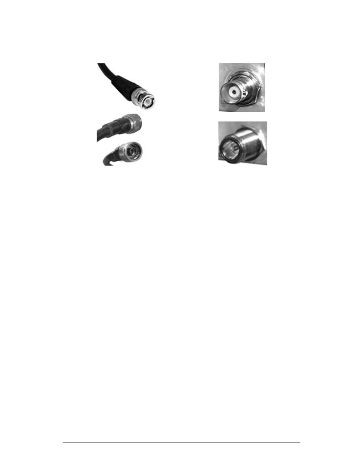
CDM-710/L Broadcast Satellite Modem MN/CDM710.IOM
Rear Panel Connectors Revision 12
4.1.1 Coaxial Cable Connections
(TOP) Bayonet Coupling Plug and Jack (Type ‘BNC’ Shown)
(BOTTOM) Threaded Coupling Plug and Jack (Type ‘N’ Shown)
Figure 4-1. Coaxial Connector Examples
The types of coaxial cables used by Comtech EF Data are ‘BNC’, ‘TNC’, ‘N’, ‘F’,
and ‘SMA’. Coaxial cables (plugs) and their mating connectors (jacks/sockets) are
available in two coupling styles – Bayonet or Threaded:
Bayonet Coupling Style – The jack has a pair of guideposts that accommodate
the plug’s lockdown slots. This lockdown design provides secure assembly
without over-tightening the connection.
Threaded Coupling Style – The jack features external threads. The plug shell
features internal threads, and has either a knurled outer surface to permit handtightening of the connection, or hex flats to accommodate torqued installation.
Connection Instructions:
Bayonet Coupling Connections – Use the plug slots to guide, and then slide the
plug onto the jack posts. Then, turn the plug clockwise until the jack posts are
fully seated within the plug slot.
Threaded Coupling Connections – Engage the plug onto the jack threads, and
then turn the plug clockwise until it is fully threaded onto the jack. Do not overtighten the connection.
4–2
Page 71
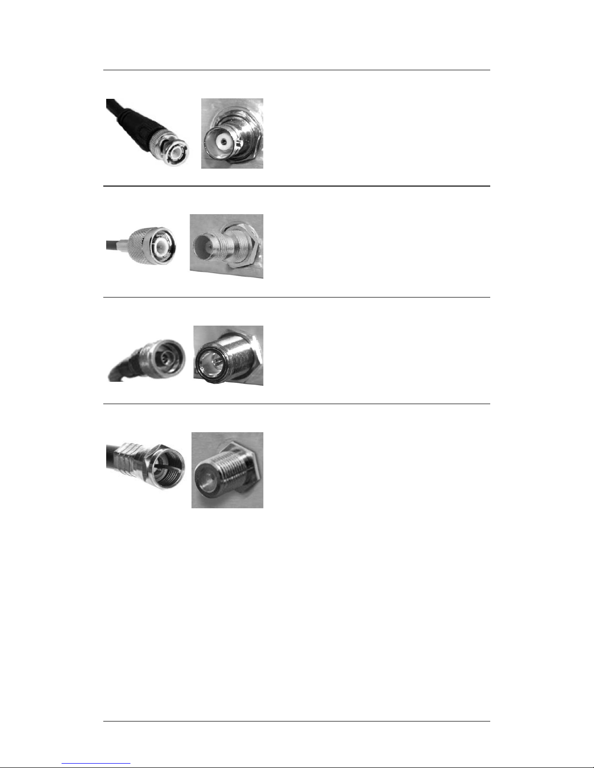
CDM-710/L Broadcast Satellite Modem MN/CDM710.IOM
Type ‘N’ connectors feature a Threaded
Type ‘F’, and Type ‘SMA’ connectors.
‘F,’ and Type ‘SMA’ connectors.
Rear Panel Connectors Revision 12
4.1.1.1 Type ‘BNC’
BNC plugs and jacks feature a Bayonet
Coupling design.
4.1.1.2 Type ‘TNC’
TNC plugs and jacks feature a Threaded
Coupling design similar to Type ‘N’, Type
4.1.1.3 Type ‘N’
4.1.1.4 Type ‘F’
Coupling design similar to Type ‘TNC’,
Type ‘F’ connectors feature a Threaded
Coupling design similar to Type ‘TNC’,
Type ‘N’, and Type ‘SMA’ connectors.
4–3
Page 72
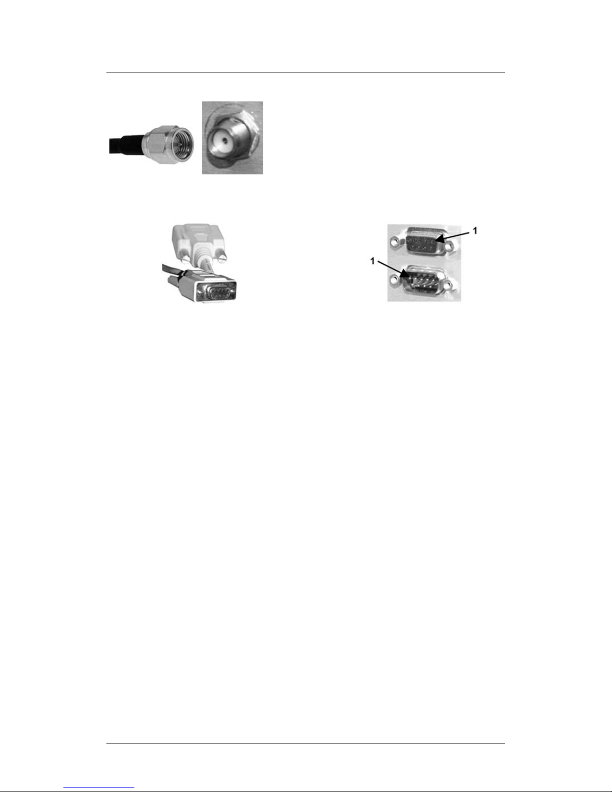
CDM-710/L Broadcast Satellite Modem MN/CDM710.IOM
Rear Panel Connectors Revision 12
4.1.1.5 Type ‘SMA’
Type ‘SMA’ connectors feature a
Threaded Coupling design similar to
Type ‘TNC’, Type ‘N’, and Type ‘F’
connectors.
4.1.2 D-Subminiature Cable Connections
Type ‘D’ Cable with Jack Screws
(Female Shown)
Type ‘D’ Chassis Receptacles with Jack Nuts:
(TOP) Female
(BOTTOM) Male
Figure 4-2. D-Subminiature Connector Examples
D-Subminiature connectors are also called Type ‘D’ or ‘D-Sub’ connectors. The
cable plug and chassis receptacle each feature a D-shaped profile that interlock
to ensure proper pin orientation and connector seating. The connector pair
features multiple rows of pins (male side) coupled to mating sockets (female
side).
Whether the gender is male or female, the cable plug features two jack screws
for secure connection to the jack nuts provided on the mating chassis receptacle.
Connection Instructions: Orient the plug to the receptacle in the proper
position. Press firmly into place. Hand tighten, or use a standard flat-blade
screwdriver, to secure the plug jack screws to the receptacle jack nuts. Do not
over-tighten.
About connector pinout tables: Figure 4-2 identifies the Pin 1 location for either
gender connector. The connector pinout tables provided in this manual base the
order of information (i.e., the “Pin #” column) on this orientation, except where
noted.
4–4
Page 73

CDM-710/L Broadcast Satellite Modem MN/CDM710.IOM
Rear Panel Connectors Revision 12
4.1.3 RJ-45, RJ-48 Cable Connections
Figure 4-3. RJ-45/RJ-48 Connector Example
The plug for an RJ-45 or RJ-48 cable features a flexible tab. The RJ-45 or RJ-48
receptacle features a mating slot. This design configuration ensures a secure
installation.
Connection Instructions (Figure 4-3): Press down the tab on the cable plug and
then insert the plug into the receptacle. The connection is complete when the
tab ‘clicks’ into position inside the receptacle.
4.1.4 USB Cable Connections
(TOP) Type ‘A’ USB Plug and Receptacle
(BOTTOM) Type ‘B’ USB Plug and Receptacle
Figure 4-4. USB Connector Examples
Universal Serial Bus connectors are also called USB connectors. A USB
connection is used as a bus-type communications or power interface between
peripheral devices. The connector pair (Figure 4-4) features a plug (male side)
coupled to its mating receptacle (female side).
4–5
Page 74

CDM-710/L Broadcast Satellite Modem MN/CDM710.IOM
Tx only
not
supports Tx Only, Rx Only, and Duplex operation.
Rear Panel Connectors Revision 12
Connection Instructions:
Type ‘A’ Connections – Slide the plug firmly into the chassis receptacle.
Type ‘B’ Connections – Orient the plug to the receptacle and push in firmly. The
Type ‘B’ cable plug and chassis receptacle each feature a D-shaped profile that
interlock to ensure proper orientation and connector seating. By design, it is
impossible to incorrectly insert the plug into the receptacle.
4.2 Unit Connectors
External cables are attached to connectors provided on the rear panel of the unit
(Figure 4-5).
Figure 4-5. CDM-710/G Rear Panel View (Rev A. and Later Chassis
Shown)
1) The initially released chassis is
operation. It does not support 1:N operation and is not upgradeable.
and does
support 1:1
This chassis is also not upgradeable to Rx only or Duplex operation.
2) The Rev. A and later chassis is required for 1:1 or 1:N operation. It
4.2.1 Power Interface Module – Standard AC Unit
As shown in Figure 4-5, the AC power interface module consists of the following
components:
Item 1 – AC Power Connector
This connector is an IEC-60320 Type C14 (male) three-prong connector, for
connection with an IEC-60320 Type C13 (female) three-prong plug. Note the
following:
4–6
Page 75
CDM-710/L Broadcast Satellite Modem MN/CDM710.IOM
Product
Configuration
Voltage
Frequency
Watts
Amps
VA
120V AC
60
83.5
0.738
89
230V AC
50
83.0
0.503
116
120V AC
60
87.2
0.770
93
230V AC
50
86.5
0.579
133
WITH THE CORRECT TYPE AND RATING.
Rear Panel Connectors Revision 12
CDM-710
(70/140 MHz)
CDM-710L
(L-Band)
LDPC+BCH 32APSK 8/9
28 Msps S2-TS 120 MHz
LDPC+BCH 32APSK 8/9
28 Msps S2-TS 120 MHz
Item 2 – Press-fit Fuse Holder
Two 20mm Slo-blo type fuses are installed here for line and neutral fusing.
4.2.1.1 AC Operation – Replace the Fuses
Figure 4-6. Replace the AC Fuses
As shown in Figure 4-5 (Item 2) and (Figure 4-6): The unit rear panel features a
fuse holder that is press-fit into the body of the IEC power module. The unit uses
two 20mm Slo-blo fuses – one each for line and neutral connections.
WARNING!
DISCONNECT THE POWER SUPPLY BEFORE PROCEEDING!
CAUTION
FOR CONTINUED OPERATOR SAFETY, ALWAYS REPLACE THE FUSES
Do these steps to replace the AC fuses (Figure 4-6):
1. Unseat the fuse holder from the IEC power module.
a. Use the slot to pry the holder outward from the IEC power module.
b. Pull the holder straight out, and then swing the holder away from the
module.
4–7
Page 76
CDM-710/L Broadcast Satellite Modem MN/CDM710.IOM
Product
Configuration
Voltage
Frequency
Watts
Amps
VA
(L-Band)
28Msps S2-TS 120 MHz
Rear Panel Connectors Revision 12
2. Remove and replace the fuses as needed. Use T2.00A 20mm fuses for
115 and 230 volt AC operation.
3. Re-seat the fuse holder in the IEC power module.
4.2.1.2 AC Operation – Apply Power
Figure 4-7. Apply AC Power to the Unit
Do these steps to apply AC power to the unit (Figure 4-7):
1. Plug the provided AC power cord female end into the unit.
2. Plug the AC power cord male end into the user-supplied power source.
3. Switch the unit ON.
4.2.2 Power Interface Module – Optional 48V DC Unit
Contact Comtech EF Data Product Support for detailed information about
connecting and supplying power, and replacing the fuses for the optional DCpowered CDM-710 or CDM-710L. Note the following:
CDM-710
(70/140 MHz)
CDM-710L
LDPC+BCH 32APSK 8/9
28Msps S2-TS 120 MHz
LDPC+BCH 32APSK 8/9
48V DC N/A 81.2 1.69 -
48V DC N/A 85.92 1.79 -
4–8
Page 77

CDM-710/L Broadcast Satellite Modem MN/CDM710.IOM
Rear Panel Connectors Revision 12
4.2.2.1 DC Operation – Replace the Fuses
For DC operation, the unit requires two different fuses. The fuses are located on
the rear panel in individual screw-in receptacles found adjacent to the terminal
block.
WARNING!
DISCONNECT THE POWER SUPPLY BEFORE PROCEEDING!
CAUTION
FOR CONTINUED OPERATOR SAFETY, ALWAYS REPLACE THE FUSES
WITH THE CORRECT TYPE AND RATING.
Do these steps to replace the DC fuses:
1. Disconnect the power supply leads.
2. Unscrew either fuse holder from its receptacle.
3. Remove and replace the T6.25A 6.3 mm x 32 mm fuses as needed.
4. Screw the fuse holder back into its receptacle.
4.2.2.2 DC Operation – Apply Power
Do these steps to apply DC power to the unit:
1. Connect the user-supplied (+) and (–) DC power leads to their respective
terminals.
Number 18 AWG minimum wires are recommended.
2. Connect the user-supplied DC power leads to the user power source.
3. Energize the power source to turn the unit ON.
4.2.3 Unit Ground Connection
Figure 4-8. Unit Ground Connection
4–9
Page 78

CDM-710/L Broadcast Satellite Modem MN/CDM710.IOM
CAUTION
ground stud during installation, configuration, and operation.
about each connector type and its connection instructions.
ON THIS CONNECTOR.
Rear Panel Connectors Revision 12
PROPER GROUNDING PROTECTION IS REQUIRED. You must connect the
equipment to the protective earth connection at all times. Use this
The AC power interface provides the safety ground.
As shown in Figure 4-5 and Figure 4-8 (Item 3): This #10-32 stud, located
adjacent to the power interface module, is used for connecting a common
chassis ground among equipment.
4.2.4 Operational Connections
See Sect. 4.1 Overview – Cabling Connections Types for information
Figure 4-9. Rear Panel Operational Connections
As shown in Figure 4-5 and Figure 4-9 (Items 4 through 10):
Item 4 – ‘J7 | Ext Ref’ Utility Connector
Use this female BNC connector to supply a master reference to the entire
chassis. The clocks on the Framer Card and the Modulator and Demodulator
Synthesizers are locked to this input, when it is used. Note that some data
interfaces have an Ext-Clk input for synchronizing the data sources. Refer to the
applicable Data Interface appendices in this manual for details.
Item 5 – ‘J1 | Tx (Transmit)’ IF Connector
CAUTION
THERE MAY BE DC VOLTAGES OF UP TO 48 VOLTS MAXIMUM PRESENT
4–10
Page 79
CDM-710/L Broadcast Satellite Modem MN/CDM710.IOM
Rear Panel Connectors Revision 12
Use this connector for Tx operation:
• CDM-710 (70/140 MHz) – BNC female connector
• CDM-710L (L-Band) – Type ‘N’ female connector
Item 6 – ‘J4 | ETHERNET’ Ethernet Management Utility Port
Use this 10/100 BaseT Ethernet RJ-45 port for operation of the Ethernet remote
control interfaces.
Table 4-1. ‘J4 | Ethernet’ Connector Pinouts
Pin # Description Direction
1 Tx+ Out
2 TX- Out
3 Rx+ In
4 N/A
5 N/A
6 Rx- In
7 N/A
8 N/A
Item 7 – ‘P1 | ALARMS’ Utility Connector
Use this DB-15M EIA-232 connector to access the Form C Alarms (relay closures).
The connector pinout depends upon whether the unit is in the Normal or
Redundancy mode for use with the CRS-170A (L-Band), CRS-180 (70/140 MHz),
or CRS-300 redundancy switches.
You may use the front panel keypad to place the unit into 1:1 mode: Config: AUX
1:1 Mask Ena/Dis Enable.
4–11
Page 80
CDM-710/L Broadcast Satellite Modem MN/CDM710.IOM
4
Unit Fault
Unit-Com
I/O
1
Ground
GND
Gnd
1:N (CRS-300/710) and 1:1 Mode (CRS-170A, CRS-180)
7
Summary Relay COM (See notes)
PR-COM
I/O
6
Aux Tx Enable
Red_Out_4
O
5
Fused -12 VDC Output (160 mA max)
-12VDC
O
12
Fused +12 VDC Output (160 mA max)
+12VDC
O
11
Serial Clock
Red_Out_1
O
10
Receive Serial Data – auxiliary channel
Red_In_3
I
2
Transmit Serial Data – auxiliary channel
Red_Out_3
O
9
Ext Carrier Off (TTL Lo = Mute, Open = Tx)
Red_In_1
I
Rear Panel Connectors Revision 12
Table 4-2. ‘P1 | Alarms’ Connector Pinouts
Normal Mode
Pin # Description Name Direction
8
15
7
14
6
13
5
12
Rx Traffic (De-energized, Faulted) (See notes)
Rx Traffic (Energized, No Fault)
Rx Traffic
Tx Traffic (De-energized, Faulted) (See notes)
Tx Traffic (Energized, No Fault)
Tx Traffic
Unit Fault (De-energized, Faulted) (See notes)
Unit Fault (Energized, No Fault)
Rx-NC
Rx-NO
Rx-COM
Tx-NC
Tx-NO
Tx-COM
Unit-NC
Unit-NO
I/O
I/O
I/O
I/O
I/O
I/O
I/O
I/O
11
3
10 No Connection NC NC
2 AGC Voltage (Rx signal level, 0-10 volts) AGC O
9 Ext Carrier Off (TTL Lo = Mute, Open = Tx) EXT-OFF I
Rx I Channel (Constellation Monitor)
Rx Q Channel (Constellation Monitor)
Rx-I
Rx-Q
Pin # Description Name Direction
8
15
14 Clock Detect Clk Det I
13 No Connection NC NC
4 Online Red_In_2 I
3 Serial Data Red_Out_2 O
Summary Relay NC (De-energized, Faulted)
Summary Relay NO (Energized, No Fault)
PR-NC
PR-NO
O
O
I/O
I/O
1 Ground GND Gnd
1) The relays have low voltage contacts with transient suppressors
across each pin to ground. The Summary Relay combines Tx, Rx,
and Unit Faults into a single relay.
2) The maximum working voltage is 18VDC or 13V AC. The maximum
current rating is 1 Amp DC or 0.5 Amp AC.
4–12
Page 81
CDM-710/L Broadcast Satellite Modem MN/CDM710.IOM
ON THIS CONNECTOR.
was not intended for customer use.
Rear Panel Connectors Revision 12
Item 8 – ‘P2 | Remote’ Serial Management Utility Connector
This DB-9M connector is intended for connection to an M&C computer or terminal
device. It is user selectable for either EIA-232 or EIA-485 (2-Wire/4-Wire) operation.
Table 4-3. ‘P2 | Remote’ Connector Pinouts
Pin # Description Direction
1 Ground --
2 RS-232 Transmit Data Out
3 RS-232 Receive Data In
4 Not Used --
5 Not Used --
6 RS-485 Receive Data B* In
7 RS-485 Receive Data A* In
8 RS-485 Transmit Data B Out
9 RS-485 Transmit Data A Out
* Use for 2-Wire EIA-485 operation
Item 9 – ‘J3 | Rx (Receive)’ IF Connector
CAUTION
THERE MAY BE DC VOLTAGES OF UP TO 48 VOLTS MAXIMUM PRESENT
Use this connector for Rx operation:
• CDM-710 (70/140 MHz) – BNC female connector
• CDM-710L (L-Band) – Type ‘N’ female connector
Item 10 – ‘J6 | Async Channel’ Utility Connector (NOT USED)
1) Asynchronous Engineering Channel operation is not
implemented in the CDM-710/L; this DB-9F connection is
therefore non-operational.
2) This connection exists on Rev. A and later chassis only. The
original production unit provided an RJ-45 connector, labeled
‘J6 | SerDes’. It served as a private communications link and
4–13
Page 82

CDM-710/L Broadcast Satellite Modem MN/CDM710.IOM
Rear Panel Connectors Revision 12
Notes:
4–14
Page 83

Chapter 5. FIRMWARE
UPDATE
5.1 Firmware Update Overview
Make sure to operate the Comtech EF Data CDM-710 or CDM-710L
High-Speed Satellite Modem with its latest available firmware.
The CDM-710/L is factory-shipped with the latest version of operating firmware.
If you need to update the firmware, you can apply the update to the modem
without having to remove it from operation. You may directly acquire the
download from Comtech EF Data’s web site (www.comtechefdata.com
receive the archive file by e-mail from Comtech EF Data Product Support.
5.1.1 Firmware Update Procedure Summary
1. Download the firmware update archive file to a user-supplied PC. The user
PC must be Microsoft Windows® compatible.
2. Make sure the User PC is connected to the base modem rear panel ‘J4 |
Ethernet’ 10/100 Base-T Ethernet M&C port. (Do NOT use the CDI-70 ‘J1’
10/100/1000 Base-T Gigabit Ethernet traffic port.)
3. Use Windows Command-line or Command Prompt to transfer, via File
Transfer Protocol (FTP), the extracted firmware files from the User PC to the
modem’s standby firmware image.
4. Use the modem front panel or the CDM-710/L HTTP Interface to configure
the modem to operate using the updated firmware image.
), or
5–1
Page 84

CDM-710/L Broadcast Satellite Modem MN/CDM710.IOM
Firmware Update Revision 12
5.1.2 About Firmware Numbers, File Versions, and
Formats
Comtech EF Data’s Web site catalogues its firmware update files by product type
(e.g., modem, converter, etc.) and specific model/optional configuration. For
example, the CDM-710 firmware download hyperlink appears as F12437x_V####
(where ‘####’ indicates the firmware version number, and ‘x’ is the revision
letter of that version).
Comtech EF Data provides its archive download files in two compressed formats
as *.exe (self-extracting) and *.zip (compressed):
• The self-extracting *.exe file does not require use of a third-party utility
program.
• Some firewalls do not allow the download of self-extracting *.exe files.
You must instead download the *.zip file, and extract the firmware files
from the download with a user-supplied third-party file archiver and
compression utility program such as PKZIP for Windows, WinZip,
ZipCentral, etc. (PKZIP for DOS is not supported due to file naming
conventions). Comtech EF Data does not provide this utility program.
For detailed information on handling archived files, read your archive utility
program’s Help documentation.
5.2 Prepare for the Firmware Download
5.2.1 Required User-supplied Items
You will need:
• A Microsoft Windows-based PC, equipped with available serial and
Ethernet ports.
• A 9-pin serial cable and an RJ-45 CAT5 Ethernet cable to connect the User
PC to the modem.
• A terminal emulator program (e.g., Tera Term or HyperTerminal).
• A compatible Web browser (e.g., Internet Explorer).
5–2
Page 85

CDM-710/L Broadcast Satellite Modem MN/CDM710.IOM
Firmware Update Revision 12
5.2.1.1 Modem Connections
Connect the User PC to the modem:
• Use the 9-pin serial cable to connect the modem ‘P2 | Remote’ port to a
serial port on the User PC.
• Use an Ethernet hub, switch, or direct cable connection to connect the
modem ‘J4 | Ethernet’ port to the Ethernet port on the User PC.
BASE MODEM firmware can only be loaded via the ‘J4 | Ethernet’ M&C
port; do not
Interface Module.
use the Ethernet Traffic port available on the CDI-70 Data
5.2.2 Configure the Terminal Emulator Program
On the User PC – Open the terminal emulator program, and then configure the
program’s serial port communication and terminal display operation:
• Baud Rate = 38400 bps
• Data Bits = 8
• Stop bits = 1
• Parity = NO
• Local Echo = ON
• Port Flow Control = NONE
• Display New Line Rx/Tx = CR
Read your terminal emulator program user guide or HELP feature for
operating and configuration instructions.
5–3
Page 86

CDM-710/L Broadcast Satellite Modem MN/CDM710.IOM
•
Chapter 9. SERIAL INTERFACE OPERATION
Firmware Update Revision 12
5.2.3 Get the Management IP Address and Firmware
Information
Chapter 7. FRONT PANEL OPERATION
• Chapter 8. ETHERNET INTERFACE OPERATION
•
Do these steps:
1. On the modem – Apply power to the unit. Your power connection varies
depending on your ordered unit (i.e., AC vs. DC operation).
2. Identify your default Management IP Address. You will not be able to access
the HTTP (Web Server) Interface without this information. See Section
5.2.3.1.
3. Get the firmware information using one of these methods:
• To use the modem Front Panel, see Section 5.2.3.2.
• To use the Serial Remote Interface, see Section 5.2.3.3.
• To use the HTTP Interface, seer Section 5.2.3.4.
5.2.3.1 Use Front Panel Operation to Find the Management IP
Address
Ethernet IP Address/Range:
192.168.001.001/24 ()
You may view the assigned Management IP Address on the SELECT: Config
Remote Ethernet Address screen.
5.2.3.2 Use Front Panel Operation to Find the Firmware
Information
You may view the base modem running M&C version at the top level screen.
Press the CLEAR key several times to view this information.
The detailed firmware information can be found within the SELECT: UTIL
Firmware Info Image#1 or Image#2 Bulk nested submenus.
Examples of these screens are as follows:
5–4
Page 87

CDM-710/L Broadcast Satellite Modem MN/CDM710.IOM
Firmware Update Revision 12
CDM-710 MODEM
Firmware Version: X.X.X
Bulk: 08/06/09
FW12437P 4.1.5
5.2.3.3 Use the Serial Interface to Find the Firmware Information
Use your terminal emulator to execute remote queries with the modem. Use
either of these remote queries to find the firmware information:
• Condensed : <0/SWR?{CR}
(returns the firmware version numbers running under Boot, Bulk1, and
Bulk2, in the form B.B.BB)
• Detailed : <0/FRW?{CR}
(returns the complete information of the firmwares running under Boot,
Bulk1, and Bulk2 in the form similar to FW-AAAAAAA B.B.BB DD/MM/YY,
where:
o FW-AAAAAAA = the firmware part number
o B.B.BB = the firmware version number
o DD/MM/YY = the firmware release date (Day/Month/Year)
5.2.3.4 Use the HTTP Interface to Find the Firmware Information
Do these steps:
1. The ‘Firmware Information’ section of the ‘Maint | Unit Info’ page provides
the firmware details as Boot, Active Bulk, and Inactive Bulk, as shown in this
example:
5–5
Page 88

CDM-710/L Broadcast Satellite Modem MN/CDM710.IOM
Firmware Update Revision 12
2. Write down your firmware information for further reference or to provide to
Comtech EF Data Product support.
5.2.4 Make a Temporary Folder (Subdirectory) on the
User PC
The temporary folder is where you store the firmware archive download. There
are several ways you can make a temporary folder on a Windows PC:
• To use the Windows Desktop, see Section 5.2.4.1.
• To use Windows Explorer, see Section 5.2.4.2.
• To use the Run and Browse windows, see Section 5.2.4.3.
• To use Windows Command-line or the Command Prompt, see Section
5.2.4.4.
After you make the temporary folder, proceed to Section 5.2.5 to download and
extract the firmware files.
1) These examples specify drive letter “c:”. You can use any valid,
writable drive letter.
2) Typical for many of the tasks that follow, type the command as
instructed and then press Enter.
5.2.4.1 Use Windows Desktop to Make a Folder
Do these steps:
1. Right-click anywhere on the desktop to open the popup submenu.
2. Select New > Folder to make the new, temporary folder on the desktop.
5–6
Page 89

CDM-710/L Broadcast Satellite Modem MN/CDM710.IOM
Firmware Update Revision 12
3. Right-click on the new folder and then select Rename from the popup
submenu. Rename this folder to “temp” or some other convenient, unused
name.
5.2.4.2 Use Windows Explorer to Make a Folder
Do these steps:
1. Left-double-click the Windows Explorer icon on the Windows Desktop.
2. Depending in your Windows OS version: select File > New > Folder, or click
your Folder Destination (e.g., Windows (C:) and then New Folder to make
the new, temporary folder in the active location.
3. Right-click the New Folder folder name, and then Rename this folder to
“temp” or some other convenient, unused name.
5.2.4.3 Use the Run and Browse Windows to Make a Folder
Select Start on the Windows taskbar and then do these steps:
1. Click Run… to open the Run window.
2. Click Browse… to open the Browse window.
5–7
Page 90

CDM-710/L Broadcast Satellite Modem MN/CDM710.IOM
Firmware Update Revision 12
3. Click New Folder. This can be an icon or a text label, depending on the
Windows OS version.
4. Right-click the New Folder folder name, and then Rename this folder to
“temp” or some other convenient, unused name.
5.2.4.4 Use Windows Command-line or Command Prompt to
Make a Folder
Select Start on the Windows taskbar and then do these steps:
1. Click Run... to open the Run window (or, depending on Windows OS version
prior to Windows 95, click the MS-DOS Prompt icon from the Main Menu).
2. Open a Command-line window:
• For Windows 95 or Windows 98 – type “command”.
• For any Windows OS versions later than Windows 98 – type “cmd” or
“command”.
• Alternately, from Start, select the All Programs > Accessories popup
submenu, and then select Command Prompt:
3. From the c:\> prompt, type either “mkdir temp” or “md temp” (both “mkdir”
and “md” mean “make directory”), and then press Enter.
There will now be a “temp” folder created and available for placement of the
firmware file download.
5–8
Page 91

CDM-710/L Broadcast Satellite Modem MN/CDM710.IOM
The update to FW12437x Version 4.0.X from an earlier version is a one-
Firmware Update Revision 12
5.2.5 BEFORE PROCEEDING: CDM-710/L Firmware
Update Restrictions
way update path. Once an update to 4.0.1 (or higher) is completed, it is
no longer possible to revert to earlier versions – if you attempt to
update the firmware to an earlier version, the modem will detect this
and disallow it as a protective measure.
The one-way update effect is necessary because reallocation of internal
memory for additional space has resulted in an incompatibility between
Firmware Ver. 4.0.1 and all earlier versions.
If you are updating your modem from Firmware Version 4.1.1 to 4.1.2 or
later, you may proceed to the Bulk Firmware Update procedure
described in the next chapter section.
Note the following:
• If updating to Firmware Ver. 4.1.1 or later from a firmware version prior
to Firmware Version 4.0.1, you must first update the modem with
Firmware Version 4.0.1 in both images before you can update the modem
to run Firmware Version 4.1.1.
With the modem running pre-FW Ver. 4.1.1 in both images, do these
steps:
1. Update the first image with Firmware Version 4.0.1.
2. Switch images.
3. Reboot the modem.
4. Update the opposite image with Firmware Version 4.0.1.
5. Reboot the modem.
6. Switch images.
7. Reboot the modem once again.
8. Proceed with the Firmware Version 4.1.1 update.
• If you are running FW Ver. 4.1.1 or later and you intend to update your
modem to a firmware version that is earlier than Firmware Version 4.1.1,
do these steps to downgrade:
5–9
Page 92
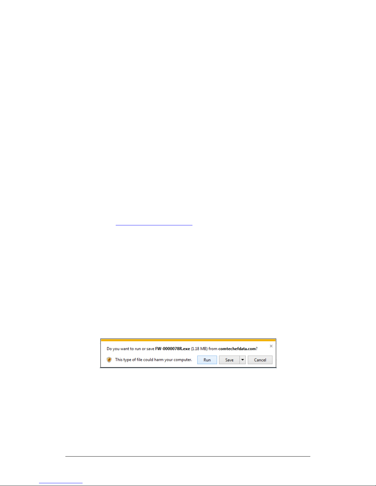
CDM-710/L Broadcast Satellite Modem MN/CDM710.IOM
and start over.
provided for reference only. Your
Firmware Update Revision 12
1. Confirm that you are running Firmware Version 4.1.1 or later in
both images.
2. Update the first image with the lower firmware version.
3. BEFORE YOU REBOOT THE MODEM, MAKE SURE TO SWITCH TO THE
OTHER IMAGE.
4. Reboot the modem.
5. Update the opposite image with the lower firmware version.
6. Reboot the modem once again.
If you reboot the modem without switching images per Step 3,
you may simply put both images back to the higher version
5.2.6 Download and Extract the Firmware Update Files
The example figures in this section are
firmware information will be different.
Do these steps:
1. Go online to www.comtechefdata.com.
2. On the Main page – Under Support Information or the Support tab, select
the Software Downloads hyperlink.
3. On the Software Downloads page – Click Download Flash and Software
Update Files.
4. On the Flash Updates Index page – Select the (Select a Product Line)
Satellite Modems hyperlink.
5. On the Modems product page – Select the CDM-710 product hyperlink;
6. Select the appropriate firmware archive EXE or ZIP file download hyperlink.
7. Once you select the EXE or ZIP hyperlink, the File Download dialogue opens
on your browser and prompts an action. You may otherwise click [Cancel] to
quit the file download process. Note the following:
• For EXE files:
o Click [Run] to open the self-extractor dialogue window. Use
[Browse] to select your destination folder. Click [Unzip] to extract
5–10
Page 93
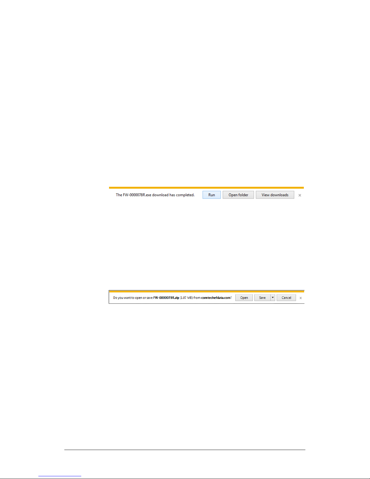
CDM-710/L Broadcast Satellite Modem MN/CDM710.IOM
Firmware Update Revision 12
the files. Your results display as per this example – click [OK] to
close . Your files are now available for transfer to the modem.
o Click [Save] to download the EXE file to your Downloads folder.
Once the download is complete the dialogue prompts you to
either [Run] the self-extracting file, or to open or view the
Windows Downloads folder for further action.
• For ZIP files:
o Click [Open] to open the archive file. Use the WinZip features to
select the files for extraction to your destination folder.
o Click [Save] to download the ZIP file to your Windows Downloads
folder. Once the download is complete the dialogue prompts you
to either [Open] the archive file, or to open or view the Windows
Downloads folder for further action.
8. If not already done with File Download > Open, you must extract, at a
minimum, these files (filenames are subject to change):
• FW12437x_CDM-710_Broadcast_X_X_X.bin (bulk image file).
5–11
Page 94

CDM-710/L Broadcast Satellite Modem MN/CDM710.IOM
Firmware Update Revision 12
• ReleaseNotes_CDM710B_X_X_X.pdf (firmware release notes).
• ftp_upgrade.pdf (firmware update procedure notes).
9. Confirm availability of the firmware files in the temporary folder. There are
several ways you can view the contents of the temporary folder on a
Windows-based PC:
• To use the Windows Desktop, see Section 5.2.5.1.
• To use Windows Command-line or Command Prompt, see Section
5.2.5.2.
• After you confirm the firmware files are in the folder, proceed to
Section 5.3 to upload the firmware update to the modem.
5.2.6.1 Use Windows Desktop to View Folder Contents
From the Windows Desktop:
1. Double-left-click the Windows Explorer icon, and then double-left-click as
needed to locate, and then open, the “temp” folder (directory) created
earlier on the Windows Desktop.
2. Use the Browse window (Start > ...Run > Browse) to locate, and then double-
click to open, the “temp” folder.
5.2.6.2 Use Windows Command-line to View Folder Contents
Using Command-line or Command Prompt:
1. Type “cd c:\temp” at the Windows Command-line prompt to change to the
temporary folder (directory) created earlier using Command-line.
2. Type “dir” to list the files extracted to the temporary folder from the
downloaded archive file.
5–12
Page 95

CDM-710/L Broadcast Satellite Modem MN/CDM710.IOM
1) Typical for all steps: “xxx.xxx.xxx.xxx” represents the assigned unit
Firmware Update Revision 12
5.3 Upload the Firmware Files and Update the
Modem
5.3.1 Important Considerations
Before you proceed with the firmware update, make sure that:
• You connect the modem ‘J4 | Ethernet’ M&C port to the user PC as
described in Section 5.2.1.1.
The BASE MODEM firmware MUST be loaded only
10/100 Base-T ‘J4 | Ethernet’ M&C port. Do NOT use the
CDI-70 ‘J1’ 10/100/1000 Base-T Gigabit Ethernet traffic port.
• Your PC is running a terminal emulation program for operation of the
modem Serial or Ethernet Telnet interfaces.
• You have noted your modem Management IP Address.
• Your PC is running a compatible Web browser for operation of the
modem HTTP Interface.
• You download or otherwise have Comtech’s latest firmware files available
on the User PC in an accessible temporary folder.
through the
5.3.2 Steps to FTP Upload the Firmware Files
Management IP Address.
2) Type all commands without quotes, and press Enter to execute.
Do these steps:
1. Use Windows Command-line to send a ping command. To ping the unit, type
“ping xxx.xxx.xxx.xxx” at the Windows Command-line prompt. The response
should confirm whether the unit is connected and communicating correctly
with the User PC.
2. Use Windows Command-line to transfer the files from the User PC to the
modem via FTP:
a. Type “ftp xxx.xxx.xxx.xxx” to open the FTP session.
b. Type “bin” to set the binary transfer mode.
c. Type “prompt”.
d. Type “hash”.
e. To begin the file transfer, type
5–13
Page 96

CDM-710/L Broadcast Satellite Modem MN/CDM710.IOM
1) If you stop the transfer before the “PROGRAMMING FLASH
update sometimes takes longer than the FTP client allows.
Firmware Update Revision 12
“put FW12437x_CDM-710_Broadcast_X_X_X.bin bulk:”
The destination “bulk:” must be all lower-case.
The process sequences through several blocks – this may take several
minutes for the transfer to occur. The modem front panel reports the
status as follows:
Programming flash sector #xx
Please wait…
SECTOR#xx PLEASE WAIT” messaging sequence is
complete, this could lead to an incomplete download,
and you must repeat the “put” command (Step 2e).
2) You must make sure to update both images with the same
firmware version for the unit to function properly.
3) The upgrade from an earlier version to 4.x.x is a one-way
update path. Once you complete an update to FW Ver.
4.0.1, it is no longer possible to revert to earlier versions.
If you attempt to update to an earlier firmware version,
the modem will detect and disallow this as a protective
measure. The unit will also disallow an attempt to switch
to an image that contains an earlier version of firmware.
Wait for the file transfer to end. When it has finished, the modem front
panel will display:
Bulk FTP done. Press CLEAR.
If you receive the “Connection closed by remote host”
message, wait another minute before continuing. The modem
f. Type “bye” to close the FTP session.
g. Close the Command-line window.
3. Select the alternate Boot Slot (Image) from the modem front panel:
5–14
Page 97

CDM-710/L Broadcast Satellite Modem MN/CDM710.IOM
See Appendix D. CDI-70 10/100/1000 BASE-T GIGABIT ETHERNET DATA
firmware for this optional data interface.
Firmware Update Revision 12
SELECT: UTIL Firmware Select, and then use the keypad (LEFT) and
(RIGHT) arrows to select the alternate image.
Firmware Info: Bootrom
Image#1 Image#2
4. Power down the modem, and then power up to reboot.
5. To verify that the PC-to-unit FTP file transfer was successful, find the current
firmware information via the front panel, or the HTTP or Serial interface (see
Sections 5.2.3.2, 5.2.3.3, or 5.2.3.4).
The modem is now operating with its latest firmware. The firmware update
process is now complete.
5.4 CDI-70 10/100/1000 Base-T Gigabit Ethernet
Interface (GBEI) FTP Upload Procedure
INTERFACE (GBEI) for information on and instructions for updating the
5.5 USB Firmware Update Procedure
Use of the front panel USB port for the firmware update process is not
available in this firmware release. Please contact Comtech EF Data
Product Support for this feature’s release schedule.
5–15
Page 98

CDM-710/L Broadcast Satellite Modem MN/CDM710.IOM
Firmware Update Revision 12
Notes:
5–16
Page 99

Chapter 6. FAST ACTIVATION
PROCEDURE
6.1 FAST Overview
The CDM-710 and CDM-710L Broadcast Satellite Modems incorporate a number
of optional features. In order to permit a lower initial cost, you may purchase the
unit with only the desired features enabled.
If you wish to upgrade the functionality of a unit at a later date, Comtech EF Data
provides Fully Accessible System Topology (FAST), which permits the purchase
and activation of options through special authorization codes. You may contact
Comtech EF Data Product Support to purchase these unique, register-specific
Fast Access Codes, and then load these codes into the modem using the front
panel keypad or the HTTP (Web Server) Interface (accessible by connecting your
PC Ethernet port to the CDM-710/L ‘J4 | Ethernet’ 10/100 Base-T M&C Ethernet
port).
FAST System Theory: FAST facilitates on-site upgrade of the operating feature
set without removing a unit from the setup. FAST technology allows you to order
a unit precisely tailored for the initial application. When your service
requirements change, you can upgrade the topology of the unit to meet these
requirements within minutes. This accelerated upgrade is possible because of
FAST’s extensive use of the programmable logic devices incorporated into
Comtech EF Data products.
FAST Implementation: Comtech EF Data implements the FAST system in the
modem at the factory. All FAST Features are available through the basic platform
unit at the time of order – FAST allows immediate activation of available options,
6–1
Page 100
CDM-710/L Broadcast Satellite Modem MN/CDM710.IOM
DVB-S
QPSK
45
DVB-DSNG
8PSK, 16QAM
45
3
DVB-S2
QPSK, 8PSK
45
QPSK, 8PSK
45
16APSK
35
DVB-S2
QPSK, 8PSK
45
DVB-S
QPSK
45
QPSK, 8PSK
45
32APSK
28
DVB-S
QPSK
45
DVB-DSNG
8PSK, 16QAM
45
FAST Activation Procedure Revision 12
after confirmation by Comtech EF Data, using the modem front panel or via the
HTTP (Web Server) Interface.
FAST Accessible Options: You may order hardware options for installation either
at the factory, or you can install and activate them on-site. The FAST Access Code
that you purchase from Comtech EF Data enables configuration of the available
hardware.
6.1.1 CDM-710/L Available FAST and FAST-accessible
Hardware Options
6.1.1.1 Transmit Configurations
Tier FAST Option Modulation
1 DVB-S QPSK 45
2
4 DVB-S2
5
6
7
8
DVB-S2
DVB-S QPSK 45
DVB-S2
DVB-S QPSK 45
DVB-DSNG 8PSK, 16QAM 45
DVB-S2
16APSK 35
QPSK, 8PSK 45
16APSK 35
QPSK, 8PSK 45
16APSK 35
Maximum Symbol
Rate (Msps)
6–2
 Loading...