

Page 1

IMPORTANT NOTE: The information contained in this document supersedes all previously published
information regarding this product. Product specifications are subject to change without prior notice.
Part Number MN/CDM600L.IOM Revision 3
CDM-600/600L
Open Network Satellite Modem (2.4 kbps – 20 Mbps)
CDM-600 – 70/140 MHz (Firmware Version 2.2.6 or higher)
CDM-600L – L-Band (Firmware Version 1.5.0 or higher)
Installation and Operation Manual
(see New in this Release – Section 1.4)
Note: This manual incorporates data for the CDM-600 and CDM-600L Manuals
Page 2

Page 3
Errata Page 1 of 4
Errata A
Comtech EF Data Documentation Update
Subject:
Date:
Original Manual Part
Number/Rev:
Errata Number/
Agile Document ID:
Agile CO Number:
Comments:
Affected content: Chapter 4 pages 4-2 and 4-3.
Update CDM-600/L Flash Upgrade Procedure
March 26, 2010
MN/CDM600L.IOM Rev 3
ER-MNCDM600L.EA3
C11327
Affected manual page content will be updated, as indicated below,
upon next formal manual revision.
Sect. 4.2 in Chapter 4 is superseded in its entirety with the pages
provided in this Errata.
AGILE DOC ID ER-MNCDM600L.EA3 THIS DOCUMENT IS NOT SUBJECT TO REVISION/UPDATE! AGILE C11327
Page 4

Errata Page 2 of 4
This page is intentionally blank.
AGILE DOC ID ER-MNCDM600L.EA3 THIS DOCUMENT IS NOT SUBJECT TO REVISION/UPDATE! AGILE C11327
Page 5
Errata Page 3 of 4
AGILE DOC ID ER-MNCDM600L.EA3 THIS DOCUMENT IS NOT SUBJECT TO REVISION/UPDATE! AGILE C11327
Page 6
Errata Page 4 of 4
AGILE DOC ID ER-MNCDM600L.EA3 THIS DOCUMENT IS NOT SUBJECT TO REVISION/UPDATE! AGILE C11327
Page 7

CDM-600/600L
Open Network Satellite Modem (2.4 kbps – 20 Mbps)
CDM-600 – 70/140 MHz (
CDM-600L – L-Band (
Installation and Operation Manual
(see New in this Release – Section 1.4)
Note: This manual incorporates data for the CDM-600 and CDM-600L Manuals
Comtech EF Data, 2114 West 7th Street, Tempe, Arizona 85281 USA, 480.333.2200, FAX: 480.333.2161
Firmware Version 2.2.6 or higher)
Firmware Version 1.5.0 or higher)
Part Number MN/CDM600L.IOM
Revision 3
June 25, 2009
Copyright © 2009 Comtech EF Data. All rights reserved. Printed in the USA.
Page 8

This page is intentionally blank.
Page 9

Table of Contents
TABLE OF CONTENTS .............................................................................................................. III
TABLES .................................................................................................................................... XIII
FIGURES .................................................................................................................................. XIII
PREFACE .................................................................................................................................. XV
About this Manual
About the Revision Level and Information Provided in this Manual ..................................................... xv
Reporting Comments or Suggestions Concerning this Manual .............................................................. xv
Conventions and References ................................................................................................................... xvi
Metric Conversion ................................................................................................................................. xvi
Cautions and Warnings .......................................................................................................................... xvi
Recommended Standard Designations ................................................................................................... xvi
Electrical Safety ....................................................................................................................................... xvi
Fuses ..................................................................................................................................................... xvii
Environmental ....................................................................................................................................... xvii
Installation............................................................................................................................................. xvii
EMC (Electromagnetic Compatibility) ................................................................................................ xviii
Warranty Policy ....................................................................................................................................... xix
Limitations of Warranty .......................................................................................................................... xx
Exclusive Remedies ................................................................................................................................ xx
Customer Support .................................................................................................................................... xxi
Online Customer Support ...................................................................................................................... xxi
.................................................................................................................................... xv
CHAPTER 1. INTRODUCTION ............................................................................................. 1–1
1.1 Overview ...................................................................................................................................... 1–1
1.1.1 Standard Features .................................................................................................................. 1–1
CDM-600/600L Common Features .............................................................................. 1–2
CDM-600L Features ...................................................................................................... 1–2
CDM-600 Features ......................................................................................................... 1–2
1.2 Functional Description ............................................................................................................... 1–3
1.3 Features ........................................................................................................................................ 1–5
1.3.1 Physical Description ............................................................................................................. 1–5
1.3.2 Compatibility ........................................................................................................................ 1–5
1.3.3 Major Assemblies ................................................................................................................. 1–5
iii
Page 10

CDM-600/600L Open Network Satellite Modem Revision 3
Table of Contents MN/CDM600L.IOM
1.3.4 Dimensional Envelopes......................................................................................................... 1–6
1.3.5 Physical Features .................................................................................................................. 1–8
1.3.5.1 Front Panel ........................................................................................................................ 1–8
1.3.5.2 Rear Panel ......................................................................................................................... 1–9
1.3.6 Hardware Options ............................................................................................................... 1–10
1.3.6.1 CDM-600L Hardware Option ......................................................................................... 1–10
1.3.6.2 CDM-600 Hardware Options .......................................................................................... 1–10
1.3.7 Data Interfaces .................................................................................................................... 1–12
1.3.8 Verification ......................................................................................................................... 1–12
1.3.9 AUPC .................................................................................................................................. 1–12
1.3.10 EDMAC .............................................................................................................................. 1–12
1.3.11 Flash Upgrading Modem Firmware .................................................................................... 1–13
1.3.12 Fully Accessible System Topology (FAST) ....................................................................... 1–13
FAST System Theory .................................................................................................. 1–13
FAST Implementation ................................................................................................. 1–13
FAST Accessible Options ........................................................................................... 1–14
1.3.13 Supporting Hardware and Software .................................................................................... 1–15
SatMac Complete Systems Operation ......................................................................... 1–15
Redundancy Applications ............................................................................................ 1–15
ODU Interoperability via FSK / EDMAC .................................................................... 1–15
1.4 New in this Release .................................................................................................................... 1–17
1.4.1 CDM-600L Modem Firmware Release Notes .................................................................... 1–17
Release Ver. 1.5.0 (7/9/08) ......................................................................................... 1–17
1.4.2 CDM-600 Modem Firmware Release Notess ..................................................................... 1–17
Release Ver. 2.2.6 (6/26/08) ....................................................................................... 1–17
1.5 Summary of Specifications ....................................................................................................... 1–18
1.5.1 Modulator
............................................................................................................................ 1–18
1.5.2 Demodulator ....................................................................................................................... 1–21
1.5.3 Data Interfaces .................................................................................................................... 1–25
1.5.4 Automatic Uplink Power Control (AUPC) ......................................................................... 1–26
1.5.5 Data Rate Ranges ................................................................................................................ 1–26
1.5.6 Framing Summary .............................................................................................................. 1–27
1.5.7 Miscellaneous ..................................................................................................................... 1–27
1.5.8 Approvals ............................................................................................................................ 1–28
1.5.9 AGC Voltage ...................................................................................................................... 1–28
CHAPTER 2. INSTALLATION .............................................................................................. 2–1
2.1 Unpacking .................................................................................................................................... 2–1
2.2 Mounting ...................................................................................................................................... 2–2
2.2.1 Optional Rear-Mounting Support Brackets .......................................................................... 2–2
2.3 Configuration .............................................................................................................................. 2–3
2.4 Select Internal IF Loop ............................................................................................................... 2–4
2.5 Connect External Cables ............................................................................................................ 2–4
iv
Page 11

CDM-600/600L Open Network Satellite Modem Revision 3
Table of Contents MN/CDM600L.IOM
CHAPTER 3. REAR PANEL CONNECTOR PINOUTS ........................................................ 3–1
3.1 Connector Overview ................................................................................................................... 3–1
3.2 IF Connections ............................................................................................................................ 3–3
3.2.1 J1 Rx IF Connectors .............................................................................................................. 3–3
3.2.2 J2 Tx IF Connectors .............................................................................................................. 3–3
3.3 Terrestrial Data Connections ..................................................................................................... 3–4
3.3.1 P3A Overhead Data Connector, DB-25M ............................................................................ 3–4
3.3.2 P3B Data Interface Connector, DB-25F ............................................................................... 3–5
3.3.3 P4A Audio Connector, DB-9F .............................................................................................. 3–6
3.3.4 G.703 Connectors ................................................................................................................. 3–6
3.3.4.1 P7 Balanced G.703 Interface Connector, DB-15F ............................................................ 3–6
3.3.4.1.1 T1/E1 RJ-48 Connection via P7 Balanced G.703 Interface Connector ................................ 3–7
3.3.4.2 J10A IDI, J11A DDO Connectors, 75Ω BNC ................................................................. 3–7
3.3.4.3 J10B Rx and J11B Tx Unbalanced G.703 Connectors, 75Ω BNC ................................... 3–8
3.4 Utility Connections ...................................................................................................................... 3–8
3.4.1 P6 Aux Serial Receptacle, USB Type ‘B’ ............................................................................ 3–8
3.4.2 J9 Ext Clk (CDM-600L) / Ext Ref (CDM-600), 50Ω BNC .................................................. 3–8
3.4.3 P4B Remote Control Interface Connector, DB-9M .............................................................. 3–9
3.4.4 P5A IDR Alarms Connector, DB-15F .................................................................................. 3–9
3.4.5 P5B Alarms Connector, DB-15M ....................................................................................... 3–10
3.4.6 J12 Ext Ref (CDM-600L) / Ext Freq Ref (CDM-600) ....................................................... 3–11
3.5 Power / Ground Connections ................................................................................................... 3–11
3.5.1 Alternating Current (AC) Power Connector (Standard)
..................................................... 3–11
3.5.2 Direct Current (DC) Power Connector (Optional, CDM-600L only) ................................. 3–12
3.5.3 Ground Connector ............................................................................................................... 3–12
CHAPTER 4. FLASH UPGRADING ...................................................................................... 4–1
4.1 Flash Updating via Internet ....................................................................................................... 4–1
4.2 Ethernet FTP Upload Procedure ............................................................................................... 4–2
CHAPTER 5. FRONT PANEL OPERATION ......................................................................... 5–1
5.1 Description ................................................................................................................................... 5–1
5.1.1 Front Panel LED Indicators .................................................................................................. 5–2
5.1.2 Front Panel Keypad ............................................................................................................... 5–3
5.1.3 Front Panel Vacuum Fluorescent Display (VFD) ................................................................. 5–3
5.2 Opening Screen ........................................................................................................................... 5–4
5.3 SELECT: (Main) Menu .............................................................................................................. 5–6
5.4 (SELECT:) CONFIGURATION ............................................................................................... 5–7
v
Page 12

CDM-600/600L Open Network Satellite Modem Revision 3
Table of Contents MN/CDM600L.IOM
5.4.1 CONFIG: ALL ...................................................................................................................... 5–8
5.4.2 CONFIG: MODE .................................................................................................................. 5–8
5.4.3 CONFIG: TX ........................................................................................................................ 5–9
5.4.3.1 CONFIG: Tx Æ TX-IF ..................................................................................................... 5–9
5.4.3.2 CONFIG: TX Æ POWER .............................................................................................. 5–10
5.4.3.3 CONFIG: TX Æ ENCODER .......................................................................................... 5–12
5.4.3.4 CONFIG: TX Æ MOD (Modulation) ............................................................................. 5–13
5.4.3.5 CONFIG: TX Æ DATA ................................................................................................. 5–13
5.4.3.6 CONFIG: TX Æ SCRAMBLER .................................................................................... 5–14
5.4.4 CONFIG: RX ...................................................................................................................... 5–14
5.4.4.1 CONFIG: RX Æ RX-IF .................................................................................................. 5–15
5.4.4.2 CONFIG: RX Æ DECODER ......................................................................................... 5–16
5.4.4.3 CONFIG: RX Æ DEMOD (Demodulation) ................................................................... 5–17
5.4.4.4 CONFIG: RX Æ DATA ................................................................................................. 5–17
5.4.4.5 CONFIG: RX Æ DESCRAMBLER ............................................................................... 5–18
5.4.4.6 CONFIG: RX Æ EbNo ................................................................................................... 5–18
5.4.5 CONFIG: CLOCKS ............................................................................................................ 5–19
5.4.5.1 CONFIG: CLOCKS Æ TX-CLOCK .............................................................................. 5–19
5.4.5
.2 CONFIG: CLOCKS Æ RX-BUFFER/CLOCK ............................................................. 5–20
5.4.5.3 CONFIG: CLOCKS Æ EXTERNAL BASEBAND CLOCK ........................................ 5–21
5.4.5.4 CONFIG: CLOCKS Æ EXT-FREQ-REF (CDM-600 ONLY) ...................................... 5–21
5.4.5.5 CONFIG: CLOCKS Æ INT-REF (CDM-600 ONLY) ................................................... 5–21
5.4.6 CONFIG: D&I (Drop & Insert) .......................................................................................... 5–22
5.4.6.1 CONFIG: D&I Æ LOOP ................................................................................................ 5–22
5.4.6.2 CONFIG: D&I Æ DRP-TYPE or INS-TYPE ................................................................ 5–22
5.4.6.3 CONFIG: D&I Æ DROP or INSERT CHAN/TS (Channel Timeslots) ......................... 5–23
5.4.7 CONFIG: FREQ-REF (CDM-600L ONLY) ...................................................................... 5–23
5.4.8 CONFIG: EDMAC ............................................................................................................. 5–23
5.4.9 CONFIG: MISC .................................................................................................................. 5–24
5.4.9.1 CONFIG: MISC Æ G.703-LINE-CODE (Ternary Code) .............................................. 5–24
5.4.9.2 CONFIG: MISC Æ IDR-ESC-TYPE ............................................................................. 5–24
5.4.9.3 CONFIG: MISC Æ ADPCM-AUDIO-VOLUME ......................................................... 5–25
5.4.9.4 CONFIG: MISC Æ HIGH-RATE-ESC .......................................................................... 5–25
5.4.9.5 CONFIG: Misc Æ WARM-UP (CDM-600 ONLY) ...................................................... 5–26
5.4.10 CONFIG: REMOTE (Remote Control) .............................................................................. 5–26
5.4.10.1 CONFIG: REMOTE Æ LOCAL or REMOTE Settings.............................................
5–27
5.4.11 CONFIG: MASK ................................................................................................................ 5–28
5.4.11.1 CONFIG: MASK Æ AIS ............................................................................................ 5–28
5.4.11.2 CONFIG: MASK Æ BUFFER (Buffer Slip) .............................................................. 5–28
5.4.11.3 CONFIG: MASK Æ Rx-IF ......................................................................................... 5–28
5.4.11.4 CONFIG: MASK Æ SAT-ALM (Satellite Alarms) ................................................... 5–29
5.4.11.5 CONFIG: MASK Æ TERR-ALM .............................................................................. 5–29
5.4.12 CONFIG: IMPEDANCE (CDM-600 ONLY) .................................................................... 5–30
5.4.13 CONFIG: STATISTICS ..................................................................................................... 5–30
5.5 SELECT: TEST ........................................................................................................................ 5–31
5.6 SELECT: INFORMATION ..................................................................................................... 5–33
5.6.1 INFO: ALL ......................................................................................................................... 5–33
5.6.2 INFO: ID ............................................................................................................................. 5–33
vi
Page 13

CDM-600/600L Open Network Satellite Modem Revision 3
Table of Contents MN/CDM600L.IOM
5.6.3 INFO: MODE ..................................................................................................................... 5–33
5.6.4 INFO: TX ............................................................................................................................ 5–34
5.6.5 INFO: RX ............................................................................................................................ 5–35
5.6.6 INFO: CLOCKS ................................................................................................................. 5–35
5.6.7 INFO: EDMAC ................................................................................................................... 5–36
5.6.8 INFO: DROP (Drop Type) ................................................................................................. 5–36
5.6.9 INFO: INSERT (Insert Type) ............................................................................................. 5–36
5.6.10 INFO: REMOTE ................................................................................................................. 5–36
5.6.11 INFO: ALARM-MASK ...................................................................................................... 5–36
5.6.12 INFO-MISC ........................................................................................................................ 5–37
5.7 SELECT: MONITOR .............................................................................................................. 5–37
5.7.1 MONITOR: LIVE-ALARMS ............................................................................................. 5–37
5.7.2 MONITOR: STORED-EVENTS ........................................................................................ 5–39
5.7.3 MONITOR: STATISTICS .................................................................................................. 5–40
5.7.4 MONITOR: RX-PARAMS ................................................................................................. 5–41
5.7.5 MONITOR: AUPC-PARAM .............................................................................................. 5–41
5.7.6 MONITOR: LNB (CDM-600L ONLY) ............................................................................. 5–41
5.7.7 MONITOR: BUC (CDM-600L ONLY) ............................................................................. 5–41
5.8 SELECT: STORE/LOAD ........................................................................................................ 5–42
5.9 SELECT: UTILITIES .............................................................................................................. 5–42
5.9.1 UTILITIES: SET-RTC ....................................................................................................... 5–42
5.9.2 UTILITIES: DISPLAY-BRIGHTNESS ............................................................................. 5–43
5.9.3 UTILITIES: LAMP............................................................................................................. 5–43
5.9.4 UTILITIES: 1:1-MANUAL-SWITCH
............................................................................... 5–43
5.9.5 UTILITIES: EDIT-CIRCUIT-ID ........................................................................................ 5–43
5.10 SELECT: ODU (OUTDOOR UNIT) ...................................................................................... 5–44
5.11 SELECT: FAST ........................................................................................................................ 5–44
5.11.1 FAST: SET .......................................................................................................................... 5–44
5.11.2 FAST: VIEW ...................................................................................................................... 5–44
CHAPTER 6. FORWARD ERROR CORRECTION OPTIONS ............................................. 6–1
6.1 Introduction ................................................................................................................................. 6–1
6.2 Viterbi .......................................................................................................................................... 6–1
6.3 Sequential ..................................................................................................................................... 6–2
6.4 Reed-Solomon Outer Codec ....................................................................................................... 6–3
6.5 Trellis Coding (FAST Option) ................................................................................................... 6–4
6.6 Turbo Product Codec (Hardware Option) ............................................................................... 6–5
6.7 TPC and Low Density Parity Check (LDPC) coding .............................................................. 6–6
vii
Page 14

CDM-600/600L Open Network Satellite Modem Revision 3
Table of Contents MN/CDM600L.IOM
6.7.1 Introduction ........................................................................................................................... 6–6
6.7.2 LDPC versus TPC ................................................................................................................. 6–7
6.7.3 End-to-End Processing Delay ............................................................................................... 6–8
6.8 Uncoded Operation (No FEC) ................................................................................................. 6–11
CHAPTER 7. AUTOMATIC UPLINK POWER CONTROL (AUPC) ..................................... 7–1
7.1 Introduction ................................................................................................................................. 7–1
7.2 Setting AUPC Parameters .......................................................................................................... 7–1
7.2.1 AUPC Target E
............................................................................................................... 7–2
b/N0
7.2.2 AUPC Max Range ................................................................................................................ 7–2
7.2.3 AUPC Alarm ......................................................................................................................... 7–2
7.2.4 Demod Unlock ...................................................................................................................... 7–3
7.3 Compensation Rate ..................................................................................................................... 7–3
7.4 Monitoring ................................................................................................................................... 7–3
CHAPTER 8. CLOCKING MODES AND DROP AND INSERT (D&I) ................................... 8–1
8.1 Introduction ................................................................................................................................. 8–1
8.2 Transmit Clocking ...................................................................................................................... 8–1
8.2.1 Internal Clock ........................................................................................................................ 8–1
8.2.2 Tx Terrestrial Clock .............................................................................................................. 8–2
8.2.3 Rx Loop-Timed, Rx=Tx ....................................................................................................... 8–2
8.2.4 Rx Loop-Timed, Rx<>Tx (Asymmetric Loop Timing) ........................................................ 8–2
8.2.5 External Clock ...................................................................................................................... 8–2
8.3 Receive Clocking ......................................................................................................................... 8–3
8.3.1 Buffer Disabled (Rx Satellite) ............................................................................................... 8–3
8.3.2 Buffer Enabled, Tx=Rx (Tx Terrestrial or External Clock) .................................................. 8–3
8.3.3 Buffer Enabled, Rx<>Tx (Tx Terrestrial or External Clock) ............................................... 8–3
8.4 X.21 Notes .................................................................................................................................... 8–3
8.5 Drop and Insert (D&I) with ESC and AUPC ........................................................................... 8–6
8.6 Frame Formats ............................................................................................................................ 8–7
8.7 Time Slot Selection ...................................................................................................................... 8–8
8.8 Drop and Insert (D&I) Clocking
............................................................................................... 8–9
8.9 Rx Buffer Clock = Insert (D&I only) ...................................................................................... 8–10
8.10 Single-Source Multiple Modems .............................................................................................. 8–10
viii
Page 15

CDM-600/600L Open Network Satellite Modem Revision 3
Table of Contents MN/CDM600L.IOM
CHAPTER 9. EDMAC CHANNEL ......................................................................................... 9–1
9.1 Theory Of Operation .................................................................................................................. 9–1
9.2 M&C Connection ........................................................................................................................ 9–2
9.3 Setup Summary ........................................................................................................................... 9–3
CHAPTER 10. ESC++ ......................................................................................................... 10–1
10.1 Introduction ............................................................................................................................... 10–1
10.2 Overhead Details ....................................................................................................................... 10–1
10.3 Available Baud Rates ................................................................................................................ 10–2
10.4 Configuration ............................................................................................................................ 10–2
10.5 Effect on Eb/No performance .................................................................................................. 10–2
CHAPTER 11. OFFSET QPSK OPERATION ..................................................................... 11–1
CHAPTER 12. OPEN NETWORK OPERATIONS............................................................... 12–1
12.1 Introduction ............................................................................................................................... 12–1
12.2 IBS .............................................................................................................................................. 12–2
12.2.1 IBS Clock/data recovery and De-jitter ................................................................................ 12–2
12.2.2 IBS Framing ........................................................................................................................ 12–2
12.2.3 IBS Engineering Service Channel ....................................................................................... 12–2
12.2.4 IBS Scrambling ................................................................................................................... 12–2
12.3 Drop and Insert ......................................................................................................................... 12–3
12.3.1 D&I Primary Data Interfaces .............................................................................................. 12–3
12.3.2 D&I Framing ....................................................................................................................... 12–3
12.4 IDR ............................................................................................................................................. 12–4
12.4.
1 IDR Primary Data Interfaces ............................................................................................... 12–4
12.4.2 IDR Framing ....................................................................................................................... 12–4
12.4.3 IDR Engineering Service Channel ...................................................................................... 12–5
APPENDIX A. CABLE DRAWINGS ...................................................................................... A-1
A.1 Introduction ................................................................................................................................. A-1
A.1.1 RS-530 to RS-422/449 Data Cable ....................................................................................... A-2
A.1.2 RS-530 to V.35 Data Cable ................................................................................................... A-3
A.1.3 RS-530 to V.35 Data Cable ................................................................................................... A-4
A.1.4 RS-530 Conversion Cable ..................................................................................................... A-5
A.1.5 Switch Programming Cable .................................................................................................. A-6
ix
Page 16

CDM-600/600L Open Network Satellite Modem Revision 3
Table of Contents MN/CDM600L.IOM
A.1.6 E1/T1 Adapter ....................................................................................................................... A-7
APPENDIX B. E
MEASUREMENT ................................................................................ B–1
B/N0
APPENDIX C. FAST ACTIVATION PROCEDURE .............................................................. C–1
C.1 Introduction ................................................................................................................................ C–1
C.2 Activation Procedure ................................................................................................................. C–1
C.2.1 Serial Number ...................................................................................................................... C–1
C.2.2 View currently installed features ......................................................................................... C–1
C.2.3 Enter Access Codes .............................................................................................................. C–2
APPENDIX D. SERIAL REMOTE CONTOL ......................................................................... D–1
D.1 Overview ..................................................................................................................................... D–1
D.2 RS-485 ......................................................................................................................................... D–1
D.3 RS-232 ......................................................................................................................................... D–2
D.4 Basic Protocol ............................................................................................................................. D–2
D.5 Packet Structure ......................................................................................................................... D–3
D.5.1 Start of Packet ...................................................................................................................... D–3
D.5.2 Target Address ..................................................................................................................... D–3
D.5.3 Address Delimiter ................................................................................................................ D–3
D.5.4 Instruction Code ................................................................................................................... D–4
D.5.5 Instruction Code Qualifier ................................................................................................... D–4
D.5.6 Optional Message Arguments .............................................................................................. D–5
D.5.7 End of Packet ....................................................................................................................... D–5
D.6 Remote Commands and Queries .............................................................................................. D–6
Section D.6 Notes: ....................................................................................................... D–7
D.6.1 Transm
it (Tx) Commands and Queries ................................................................................ D–8
D.6.2 Receive (Rx) Commands and Queries ............................................................................... D–15
D.6.3 Unit Commands and Queries ............................................................................................. D–20
D.6.4 Queries ............................................................................................................................... D–26
D.6.5 Bulk Commands ................................................................................................................. D–31
D.6.6 BUC Commands and Queries (CDM-600L ONLY) ......................................................... D–34
D.6.7 LNB Commands and Queries (CDM-600L ONLY) .......................................................... D–36
D.6.8 High-Stability Reference Option Commands and Queries (CDM-600 ONLY) ................ D–37
APPENDIX E. ODU (CSAT-5060, KST-2000A/B) OPERATION VIA THE CDM-600 .......... E–1
E.1 Introduction ................................................................................................................................ E–1
E.2 ODU Operations via Serial Remote Control ........................................................................... E–2
x
Page 17

CDM-600/600L Open Network Satellite Modem Revision 3
Table of Contents MN/CDM600L.IOM
E.2.1 Remote Control Address Setup ............................................................................................. E–2
E.3 ODU Operations via the CDM-600 Front Panel ..................................................................... E–3
E.3.1 ODU Operation – Front Panel Menu Tree (Basic) ............................................................... E–4
E.3.2 (SELECT:) (Main) Menu ...................................................................................................... E–5
E.3.3 (SELECT:) ODU – Product-specific Menu Operations ........................................................ E–5
E.3.3.1 (SELECT:) ODU (CSAT-5060 Transceiver) .................................................................... E–8
E.3.3.1.1 ODU: ENABLE Æ SYSTEM TYPE=STANDALONE ...................................................... E–8
E.3.3.1.2 ODU: ENABLE Æ SYSTEM TYPE=1:1 ............................................................................. E–8
1:1 MONITOR & CONTROL ÆODU#1 or ODU#2 .................................................. E–9
1:1 MONITOR & CONTROL ÆREDUNDANCY-BOX ........................................... E–9
E.3.3.1.3 COMMON ‘ODU SELECT’ SUBMENU .......................................................................... E–10
E.3.3.1.3.1 ODU SELECT: CONFIGURATION ................................................................ E–10
CONFIGURATION Æ TX-PARAMETERS ............................................................. E–10
CONFIGURATION Æ TX-PARAMETERS Æ SLOPE.................................................. E–11
CONFIGURATION Æ RX-PARAMETERS ............................................................. E–11
CONFIGURATION Æ RX-PARAMETERS Æ SLOPE ................................................. E–11
CONFIGURATION Æ LNA-PARAMETERS .......................................................... E–11
CONFIGURATION Æ MISCELLANEOUS ............................................................. E–12
E.3.3.1.3.2 ODU SELECT: MONITOR .............................................................................. E–13
MONITOR: TRANSMIT ........................................................................................... E–13
MONITOR: RECEIVE ............................................................................................... E–13
MONITOR: MISCELLANEOUS ............................................................................... E–13
MONITOR: POWER-SUPPLIES ............................................................................... E–13
E.3.3.1.3.3 ODU SELECT: ALARMS ................................................................................ E–14
ALARMS: CURRENT-ALARMS ............................................................................. E–14
ALARMS: STORED-ALARMS ................................................................................ E–14
E.3.3.
1.3.4 ODU SELECT: INFORMATION ..................................................................... E–15
INFORMATION: MODEL ........................................................................................ E–15
INFORMATION: TX ................................................................................................. E–15
INFORMATION: RX ................................................................................................. E–15
INFORMATION: MISC ............................................................................................. E–15
INFORMATION: LNA .............................................................................................. E–16
E.3.3.2 (SELECT:) ODU (KST-2000A/B Transceiver) .............................................................. E–16
ODU: STANDALONE Æ KST SELECT .................................................................. E–16
E.3.3.2.1 KST SELECT: CONFIGURATION .................................................................................... E–16
CONFIGURATION Æ TX-PARAM ......................................................................... E–17
CONFIGURATION Æ RX-PARAM ......................................................................... E–17
CONFIGURATION Æ RX-PARAM Æ BAND ........................................................ E–18
CONFIGURATION Æ MISCELLANEOUS ............................................................. E–18
E.3.3.2.2 KST SELECT: INFORMATION ......................................................................................... E–18
INFORMATION Æ MODEL ..................................................................................... E–19
INFORMATION Æ TX+RX-PARAM ...................................................................... E–19
INFORMATION Æ MISC ......................................................................................... E–19
INFORMATION Æ NUMBERS ............................................................................... E–19
E.3.3.2.3 KST SELECT: ALARMS ..................................................................................................... E–20
APPENDIX F. ODU (BUC, LNB) OPERATION VIA THE CDM-600L ................................... F–1
xi
Page 18

CDM-600/600L Open Network Satellite Modem Revision 3
Table of Contents MN/CDM600L.IOM
F.1 Introduction ................................................................................................................................. F–1
F.2 ODU Operations via Serial Remote Control ............................................................................ F–1
F.2.1 Remote Control Address Setup ............................................................................................. F–1
F.3 ODU Operations via the CDM-600L Front Panel ................................................................... F–2
F.3.1 ODU Operation – Front Panel Menu Tree ............................................................................ F–3
F.3.2 Front Panel Menu Operations ............................................................................................... F–4
F.3.3 SELECT: (Main) Menu ........................................................................................................ F–4
F.3.4 (SELECT:) ODU (Outdoor Unit) ......................................................................................... F–5
F.3.4.1 ODU: BUC-FSK ............................................................................................................... F–5
F.3.4.2 ODU: BUC-CONFIG ....................................................................................................... F–6
F.3.4.3 ODU: BUC-LO ................................................................................................................. F–6
F.3.4.4 ODU: LNB-CONFIG ........................................................................................................ F–7
F.3.4.5 ODU: LNB-LO ................................................................................................................. F–7
F.3.5 (SELECT:) MONITOR ......................................................................................................... F–8
F.3.5.1 MONITOR: LNB .............................................................................................................. F–8
F.3.5.2 MONITOR: BUC .............................................................................................................. F–8
APPENDIX G. BUC FSK COMMUNICATIONS (CDM-600L) ............................................... G–1
APPENDIX H. DST SETUP (CDM-600L) ............................................................................. H–1
H.1 Overview ..................................................................................................................................... H–1
H.2 Initial Operation ......................................................................................................................... H–1
H.2.1 Prior to Turning On Power ................................................................................................... H–1
H.2.2 Initial Power Up – Modem Only .......................................................................................... H–2
H.3 LO, Mix, and Spectrum (Inversion) Settings ........................................................................... H–2
H.4 Applying Power To The
BUC ................................................................................................... H–3
H.5 Tx Side Setup .............................................................................................................................. H–4
H.6 Initial Operation of the Modem with the BUC and LNB ....................................................... H–5
H.6.1 RX Side Setup ...................................................................................................................... H–5
APPENDIX J. KT/11202-1 STEP ATTENUATOR KIT (CDM-600L) ..................................... J–1
J.1 Introduction ................................................................................................................................. J–1
J.2 Kit Installation ............................................................................................................................ J–1
J.3 Front Panel Operation ................................................................................................................ J–3
CONFIG: TX Æ POWER ............................................................................................ J–3
CONFIG: TX Æ POWER Æ MODE Æ MANUAL ................................................... J–3
CONFIG: TX Æ POWER Æ MODE Æ MANUAL-LOW ......................................... J–3
CONFIG: TX Æ POWER Æ MODE Æ AUPC .......................................................... J–4
xii
Page 19

CDM-600/600L Open Network Satellite Modem Revision 3
Table of Contents MN/CDM600L.IOM
CONFIG: TX Æ POWER Æ MODE Æ AUPC-LOW ................................................ J–4
CONFIG: TX Æ POWER Æ MODE Æ AUPC Æ TARGET-EbNo/RANGE ........... J–4
CONFIG: TX Æ POWER Æ MODE Æ AUPC-LOW Æ TARGET-EbNo/RANGE . J–4
CONFIG: TX Æ POWER Æ MODE Æ AUPC/AUPC-LOW Æ ALARM/ACTION J–4
J.4 Remote Control Operation ......................................................................................................... J–5
Tables
Table 1-1. CDM-600/600L Rear Panel Connectors .................................................................................. 1–7
Table 3-1. Rear Panel External Connections ............................................................................................ 3–2
Table 6-1. Viterbi Decoding Summary ..................................................................................................... 6–2
Table 6-2. Sequential Decoding Summary ............................................................................................... 6–3
Table 6-3. Concatenated Reed-Solomon Coding Summary ..................................................................... 6–4
Table 6-4. 8-PSK/TCM Coding Summary ............................................................................................... 6–5
Table 6-5. Available TPC and LDPC Modes ........................................................................................... 6–8
Table 6-6. Turbo Product Coding Processing Delay Comparison ............................................................ 6–9
Table 6-7. Comparison of all Comtech EF Data TPC and LDPC Modes ............................................... 6–10
Table 6-8. TPC and LDPC Summary ..................................................................................................... 6–10
Figures
Figure 1-1. CDM-600/600L Open Network Satellite Modem (CDM-600L shown) ................................ 1–1
Figure 1-2. CDM-600/600L Open Network Satellite Modem Block Diagrams ....................................... 1–4
Figure 1-3. CDM-600L Dimensional Envelope ....................................................................................... 1–6
Figure 1-4. CDM-600 Dimensional Envelope .......................................................................................... 1–7
Figure 1-5. Front Panel View (CDM-600L shown) .................................................................................. 1–8
Figure 1-6. Rear Panel View ..................................................................................................................... 1–9
Figure 2-1. Optional Rear-Mounting Support Brackets Installation ......................................................... 2–3
Figure 3-1. CDM-600/600L Rear Panel ................................................................................................... 3–1
Figure 3-2. CN-0000268 DB-15M Æ RJ-48F Adapter for T1/E1 Operation........................................... 3–7
Figure 4-1. Flash Update via Internet ....................................................................................................... 4–1
Figure 5-1. CDM-600/600L – Front Panel View (CDM-600L shown) .................................................... 5–1
Figure 5-2. CDM-600/600L – Principle Menu Tree ................................................................................. 5–5
Figure 5-3. Loopback Modes .................................................................................................................. 5–32
Figure 6-1. Viterbi Decoding .................................................................................................................. 6–13
Figure 6-2. Sequential Decoding 64 kbps .............................................................................................. 6–14
Figure 6-3. Sequential Decoding 1024 kbps ........................................................................................... 6–15
Figure 6-4. Sequential Decoding 2048 kbps ........................................................................................... 6–16
Figure 6-5. Viterbi with concatenated Reed-Solomon Outer Code ........................................................ 6–17
Figure 6-6. Sequential with concatenated Reed-Solomon Outer Code ................................................... 6–18
Figure 6-7. 8-PSK/TCM Rate 2/3 with and without concatenated Reed-Solomon Outer Code ................ 6–19
Figure 6-8. Comtech EF Data Turbo Product Codec Rate 3/4 QPSK/OQPSK, 8-PSK and 16-QAM ............ 6–20
Figure 6-9. Comtech EF Data Turbo Product Codec Rate 7/8 QPSK/OQPSK, 8-PSK and 16-QAM ... 6–21
Figure 6-10. Rate 1/2 QPSK, Rate 0.95 QPSK and Rate 0.95 8-PSK ........................................................... 6–22
xiii
Page 20

CDM-600/600L Open Network Satellite Modem Revision 3
Table of Contents MN/CDM600L.IOM
Figure 6-11. Rate 21/44 BPSK and Rate 5/16 BPSK Turbo .................................................................... 6–23
Figure 6-12. 16-QAM Viterbi, Rate 3/4 and Rate 7/8 with 220,200 Reed-Solomon Outer Code ........... 6–24
Figure 6-13. Differential Encoding – No FEC, No Scrambling ............................................................... 6–25
Figure 6-14. LDPC, Rate 1/2, BPSK, (O)QPSK ...................................................................................... 6–26
Figure 6-15. LDPC, Rate 2/3, (O)QPSK / 8-PSK / 8-QAM .................................................................... 6–27
Figure 6-16. LDPC, Rate 3/4, (O)QPSK / 8-QAM ................................................................................. 6–28
Figure 6-17. LDPC, Rate 3/4, 8-PSK / 16-QAM ..................................................................................... 6–29
Figure 8-1. Tx Clock Modes ..................................................................................................................... 8–4
Figure 8-2. Rx Clock Modes ..................................................................................................................... 8–5
Figure 8-3. Supported T1 and E1 Framing formats .................................................................................. 8–7
Figure 8-4. Drop and Insert Clocking ....................................................................................................... 8–9
Figure 8-5. Single-Source Multiple Modems (Looming) ....................................................................... 8–10
Figure 8-6. Single-Source Multiple Modems (Daisy-chain) ................................................................... 8–10
Figure A-1. DCE Conversion Cable: RS-530 to RS-422/449 (CA/WR0049) ......................................... A-2
Figure A-2. DCE Conversion Cable: RS-530 to V.35 (CA/WR0059) .................................................... A-3
Figure A-3. DCE Conversion Cable: RS-530 (CA/WR9718-1) .............................................................. A-4
Figure A-4. DCE Conversion Cable: RS-530 to V.35 ............................................................................. A-5
Figure A-5. Switch Programming Cable .................................................................................................. A-6
Figure A-6. E1/T1 DB-15 Æ RJ-48 Adapter (CN-0000268) .................................................................. A-7
Figure E-1. CDM-600 Front Panel View .................................................................................................. E–3
Figure E-2. CDM-600 ODU Operation Principal Menu Tree .................................................................. E–4
Figure E-3. (SELECT:) ODU Æ CSAT-5060 Transceiver Menu Tree ................................................... E–6
Figure E-4. (SELECT:) ODU Æ KST-2000A/B Transceiver Menu Tree ................................................ E–7
Figure F-1. CDM-600L Front Panel View ................................................................................................ F–2
Figure F-2. CDM-600L ODU Operation Principal Menu Tree ................................................................ F–3
Figure J-1. KT/11202-1 External 20 dB Step Attenuator Kit ................................................................... J–2
xiv
Page 21

PREFACE
About this Manual
This manual provides installation and operation information for the Comtech EF Data CDM-600 and
CDM-600L Open Network Satellite Modems. This is a technical document intended for earth station
engineers, technicians, and operators responsible for the operation and maintenance of the
CDM-600/600L.
These two modems are essentially identical in their operation:
• The CDM-600 operates in the 70/140MHz IF band and includes support for externally
connected Comtech EF Data Transceivers (CSAT-5060, KST-2000A/B)
• The CDM-600L operates at L-Band and includes support for externally connected Block
Upconverters (BUCs) and Low-Noise Block Downcoverters (LNBs).
About the Revision Level and Information Provided in this Manual
This revision incorporates the CDM-600 Satellite Modem Installation and Operation Manual
(CEFD P/N MN/CDM600.IOM Revision 7). It is intended replace both CEFD MN/CDM600.IOM
and the previous version of this document, CEFD P/N MN/CDM600L.IOM (Revision 2) in their
entirety. All content from both documents has been integrated and reorganized to conform to
current Comtech EF Data Technical Publications Standards and Practices.
Reporting Comments or Suggestions Concerning this Manual
Comments and suggestions regarding the content and design of this manual will be appreciated.
To submit comments, please contact the Comtech EF Data Technical Publications Department:
TechnicalPublications@comtechefdata.com
xv
.
Page 22
CDM-600/600L Open Network Satellite Modem Revision 3
Preface MN/CDM600L.IOM
Conventions and References
Metric Conversion
Metric conversion information is located on the inside back cover of this manual. This information
is provided to assist the operator in cross-referencing non-metric to metric conversions.
Cautions and Warnings
CAUTION indicates a hazardous situation that, if not avoided, may
result in minor or moderate injury. CAUTION may also be used to
CAUTION
WARNING
IMPORTANT
indicate other unsafe practices or risks of property damage.
WARNING indicates a potentially hazardous situation that, if not
avoided, could result in death or serious injury.
Indicates information critical for proper equipment function.
Recommended Standard Designations
Recommended Standard (RS) is equivalent to the new designation of the Electronic Industries
Association (EIA). While either designation is acceptable, Comtech EF Data has elected to
continue use of the old (RS) designation in its documentation.
Electrical Safety
The user should make special note of the following information and instructions:
IMPORTANT
The CDM-600/600L Satellite Modem has been sh own to com ply with t he follow ing safety s tandard:
• EN 60950: Safety of Information Technology Equipment, including Electrical Business
Machines.
The equipment is rated for operation over the range 100 - 240 VAC.
The CDM-600 has a maximum power consumption of 40 Watts and draws a maximum of 400mA.
The CDM-600L has a maximum power consumption of 290 Watts including maximum BUC
power supply load, and draws a maximum of 2.9 A. The CDM-600L DC-powered version is
rated for operation over the range of 38 to 60 VDC input.
xvi
Page 23

CDM-600/600L Open Network Satellite Modem Revision 3
Preface MN/CDM600L.IOM
Fuses
The AC-powered CDM-600/600L is fitted with two fuses – one each for line and neutral
connections. These are contained within the body of the IEC power inlet connector, behind a small
plastic flap.
For the CDM-600:
• For 115 VAC operation, use T1.25A, slow-blow 20mm fuses.
• For 230 VAC operation, use T0.75A, slow-blow 20mm fuses.
For the CDM-600L:
• For 115 and 230 VAC operation, use T5.0A, slow-blow 20 mm fuses (P/N FS/5ASB-IEC).
The DC-powered CDM-600L is fitted with two fuses – one each for positive and negative
connections. These are contained within the body of the power inlet, behind a small plastic flap.
• For 38 to 60 VDC operation if the modem has no BUC power supply, use T3.15A,
slow-blow 20mm fuses
• For 38 to 60 VDC operation if the modem is fitted with internal BUC power supply,
use T8.0A, slow-blow 20mm fuses.
FOR CONTINUED OPERATOR SAFETY, ALWAYS REPLACE THE FUSES WITH
CAUTION
THE CORRECT TYPE AND RATING.
Environmental
The CDM-600/600L must not be operated in an environment where the unit is exposed to
extremes of temperature outside the ambient range 0 to 50°C (32° to 122°F), precipitation,
condensation, or humid atmospheres above 95% RH, altitudes (non-pressurized) greater than
2000 meters, excessive dust or vibration, flammable gases, corrosive or explosive atmospheres.
Operation in vehicles or other transportable installations that are equipped to provide a stable
environment is permitted. If such vehicles do not provide a stable environment, safety of the
equipment to EN60950 may not be guaranteed.
Installation
CDM-600/600L AC Modem Installation: The installation and connection to the line supply
must be made in compliance to local or national wiring codes and regulations.
The CDM-600/600L is designed for connection to a power system that has separate ground, line
and neutral conductors. The equipment is not designed for connection to a power system that has
no direct connection to ground.
The CDM-600/600L is shipped with a line inlet cable suitable for use in the country of operation.
If it is necessary to replace this cable, ensure the replacement has an equivalent specification.
Examples of acceptable ratings for the cable include HAR, BASEC and HOXXX-X. Examples of
xvii
Page 24
CDM-600/600L Open Network Satellite Modem Revision 3
Preface MN/CDM600L.IOM
acceptable connector ratings include VDE, NF-USE, UL, CSA, OVE, CEBEC, NEMKO,
DEMKO, BS1636A, BSI, SETI, IMQ, KEMA-KEUR and SEV.
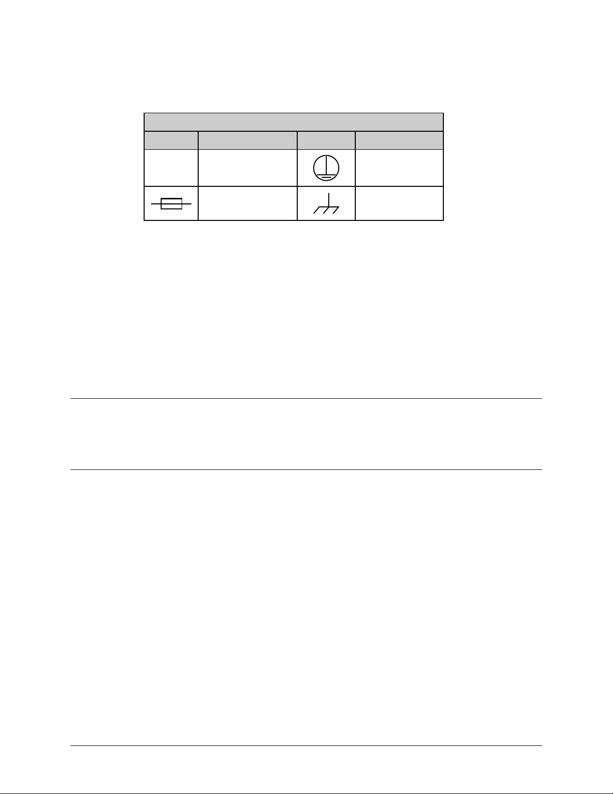
International Symbols
Symbol Definition Symbol Definition
~
CDM-600L DC Modem Installation: The DC input CDM-600L is connected to a nominal 48
VDC prime power source. The DC input is isolated from the chassis and from the DC output to
the BUC if equipped with internal BUC power supply. The chassis may be connected to a local
system ground using a separate wire to the ground stud on the back of the chassis. Since the DC
input is isolated, either the positive or the negative side of the DC input may be common with
local ground. Labeling on the back of the chassis indicates the positive and negative terminals of
the input power socket.
The modem is supplied with a 2-wire power cable (CEFD part number CA/WR10327-1) with one
end terminated with a connector that mates with the modem input power socket. Positive DC
input is on the red wire, while negative DC input is on the black wire. The DC input connector is
Molex PN 03-12-1026 with Molex PN 08-12-1222 pins.
Alternating Current
Fuse
Protective Earth
Chassis Ground
Telecommunications Terminal Equipment Directive
In accordance with the Telecommunications Terminal Equipment Directive 91/263/EEC, this
equipment should not be directly connected to the Public Telecommunications Network.
EMC (Electromagnetic Compatibility)
In accordance with European Directive 89/336/EEC, the CDM-600/600L Modem has been
shown, by independent testing, to comply with the following standards:
Emissions: EN 55022 Class B - Limits and methods of measurement of radio
interference characteristics of Information Technology Equipment.
(Also tested to FCC Part 15 Class B)
Immunity: EN 50082 Part 1 - Generic immunity standard, Part 1: Domestic,
commercial and light industrial environment.
Additionally, the CDM-600/600L has been shown to comply with the following standards:
EN 61000-3-2 Harmonic Currents Emission
EN 61000-3-3 Voltage Fluctuations and Flicker
EN 61000-4-2 ESD Immunity
EN 61000-4-4 EFT Burst Immunity
EN 61000-4-5 Surge Immunity
EN 61000-4-6 RF Conducted Immunity
EN 61000-4-8 Power frequency Magnetic Field Immunity
xviii
Page 25

CDM-600/600L Open Network Satellite Modem Revision 3
Preface MN/CDM600L.IOM
EN 61000-4-9 Pulse Magnetic Field Immunity
EN 61000-4-11 Voltage Dips, Interruptions, and Variations Immunity
EN 61000-4-13 Immunity to Harmonics
To ensure that the Modem continues to comply with these standards,
IMPORTANT
• Connections to the transmit and receive IF ports (Type ‘BNC’ female connectors for the
• All 'D' type connectors attached to the rear panel must have back-shells that provide
• The equipment must be operated with its cover on at all times. If it becomes necessary to
observe the following instructions:
CDM-600, Type ‘N’ or ‘F’ female connectors for the CDM-600L) should be made using
a good quality coaxial cable; e.g., RG58/U (50Ω) or RG59/U (75Ω).
continuous metallic shielding. Cable with a continuous outer shield (either foil or braid,
or both) must be used, and the shield must be bonded to the back-shell.
remove the cover, the user should ensure that the cover is correctly re-fitted before
normal operation commences.
Warrant y Policy
Comtech EF Data products are warranted against defects in material and workmanship
for a specific period from the date of shipment, and this period varies by product. In
most cases, the warranty period is two years. During the warranty period, Comtech EF
Data will, at its option, repair or replace products that prove to be defective. Repairs are
warranted for the remainder of the original warranty or a 90 day extended warranty,
whichever is longer. Contact Comtech EF Data for the warranty period specific to the
product purchased.
For equipment under warranty, the owner is responsible for freight to Comtech EF Data
and all related customs, taxes, tariffs, insurance, etc. Comtech EF Data is responsible for
the freight charges only for return of the equipment from the factory to the owner.
Comtech EF Data will return the equipment by the same method (i.e., Air, Express,
Surface) as the equipment was sent to Comtech EF Data.
All equipment returned for warranty repair must have a valid RMA number issued prior
to return and be marked clearly on the return packaging. Comtech EF Data strongly
recommends all equipment be returned in its original packaging.
Comtech EF Data Corporation’s obligations under this warranty are limited to repair or
replacement of failed parts, and the return shipment to the buyer of the repaired or
replaced parts.
xix
Page 26

CDM-600/600L Open Network Satellite Modem Revision 3
Preface MN/CDM600L.IOM
Limitations of Warranty
The warranty does not apply to any part of a product that has been installed, altered,
repaired, or misused in any way that, in the opinion of Comtech EF Data Corporation,
would affect the reliability or detracts from the performance of any part of the product, or
is damaged as the result of use in a way or with equipment that had not been previously
approved by Comtech EF Data Corporation.
The warranty does not apply to any product or parts thereof where the serial number or the
serial number of any of its parts has been altered, defaced, or removed.
The warranty does not cover damage or loss incurred in transportation of the product.
The warranty does not cover replacement or repair necessitated by loss or damage from
any cause beyond the control of Comtech EF Data Corporation, such as lightning or other
natural and weather related events or wartime environments.
The warranty does not cover any labor involved in the removal and or reinstallation of
warranted equipment or parts on site, or any labor required to diagnose the necessity for
repair or replacement.
The warranty excludes any responsibility by Comtech EF Data Corporation for incidental
or consequential damages arising from the use of the equipment or products, or for any
inability to use them either separate from or in combination with any other equipment or
products.
A fixed charge established for each product will be imposed for all equipment returned
for warranty repair where Comtech EF Data Corporation cannot identify the cause of the
reported failure.
Exclusive Remedies
Comtech EF Data Corporation’s warranty, as stated is in lieu of all other warranties,
expressed, implied, or statutory, including those of merchantability and fitness for a
particular purpose. The buyer shall pass on to any purchaser, lessee, or other user of
Comtech EF Data Corporation’s products, the aforementioned warranty, and shall
indemnify and hold harmless Comtech EF Data Corporation from any claims or liability
of such purchaser, lessee, or user based upon allegations that the buyer, its agents, or
employees have made additional warranties or representations as to product preference or
use.
The remedies provided herein are the buyer’s sole and exclusive remedies. Comtech EF
Data shall not be liable for any direct, indirect, special, incidental, or consequential
damages, whether based on contract, tort, or any other legal theory.
xx
Page 27

CDM-600/600L Open Network Satellite Modem Revision 3
Preface MN/CDM600L.IOM
Customer Support
Contact the Comtech EF Data Customer Support Department for:
• Product support or training
• Reporting comments or suggestions concerning manuals
• Information on upgrading or returning a product
A Customer Support representative may be reached at:
Comtech EF Data
Attention: Customer Support Department
2114 West 7th Street
Tempe, Arizona 85281 USA
480.333.2200 (Main Comtech EF Data number)
480.333.4357 (Customer Support Desk)
480.333.2161 FAX
To return a Comtech EF Data product (in-warranty and out-of-warranty) for repair or
replacement:
• Contact the Comtech EF Data Customer Support Department. Be prepared to supply the
Customer Support representative with the model number, serial number, and a description
of the problem.
• Request a Return Material Authorization (RMA) number from the Comtech EF Data
Customer Support representative.
• Pack the product in its original shipping carton/packaging to ensure th at the product is not
damaged during shipping.
• Ship the product back to Comtech EF Data. (Shipping charges should be prepaid.)
Online Customer Support
An RMA number request can be requested electronically by contacting the Customer Support
Department through the online support page at
• Click on “Service” for detailed instructions on our return procedures.
• Click on the “RMA Request Form” hyperlink, then fill out the form completely before
sending.
• Send e-mail to the Customer Support Department at service@comtechefdata.com.
For information regarding this product’s warranty policy, refer to the Warranty Policy, p.xix.
www.comtechefdata.com/support.asp:
xxi
Page 28

CDM-600/600L Open Network Satellite Modem Revision 3
Preface MN/CDM600L.IOM
Notes:
xxii
Page 29
Chapter 1. INTRODUCTION
1.1 Overview
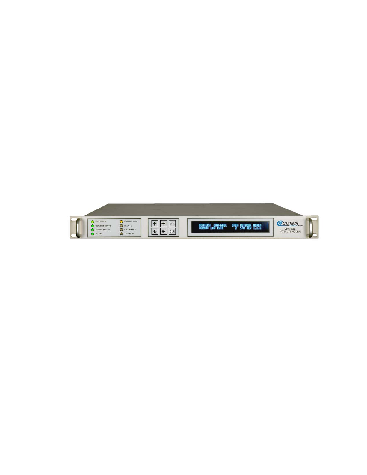
The CDM-600/600L Open Network Satellite Modem is intended for both Intelsat and closed
network applications. Apart from the IF frequency band, the two modems are essentially
identical: The CDM-600L (Figure 1-1) operates on the L-Band freq
the 70/140 MHz IF version of the same modem.
Figure 1-1. CDM-600/600L Open Network Satellite Modem (CDM-600L shown)
1.1.1 Standard Features
uency, while the CDM-600 is
The CDM-600/600L provides a wealth of standard features which go far beyond the basic requirements
of the Intelsat specifications:
• Low rate variable data rates – 2.4 kbps to 5.0 Mbps
• Mid-rate variable data rates – 2.4 kbps to 10.0 Mbps
• High-rate variable data rates – 2.4 kbps to 20.0 Mbps
• Selectable 50Ω / 75Ω IF port impedance (CDM-600)
• Asymmetric Loop Timing
• Modulation Types – BPSK, QPSK, and OQPSK
• Embedded Distant-end Monitor and Control (EDMAC) (see Note)
• Automatic Uplink Power Control (AUPC)
• Firmware – Flash Upgrading
• 1:1 and 1:10 redundancy switch compatibility
1–1
Page 30

CDM-600/600L Open Network Satellite Modem Revision 3
Introduction MN/CDM600L.IOM
EDMAC Note: In EDMAC mode, an additional 5% overhead is combined with the traffic
data (1.5% in Turbo BPSK modes, Turbo Rate 1/2 QPSK/OQPSK, and all data rates greater
than 2 Mbps), which permits Monitor & Control (M&C) information to be added
transparently to the user, allowing access to the distant-end modem. This mode does not
require any additional cabling at either the local or distant-end modems; access to EDMAC is
via the standard M&C control port.
Full M&C is possible and, importantly, the on/off status of the carrier at the distant-end carrier
can be controlled. In addition, as of Firmware Ver. 1.2.0 (CDM-600L) or 1.5.0 (CDM-600) and
higher, the proprietary D&I++ framing mode is available. This combines Drop & Insert (D&I)
operation with a similar EDMAC link and a 2.2% overhead.
CDM-600/600L Common Features
• Compliance with IESS-308 / -309/ -310 / -315 specifications, with significant features
added in Closed Network modes.
• Variable data rates from 2.4 kbps to 20 Mbps, in BPSK, QPSK, Offset QPSK, 8-PSK,
8-QAM, and 16-QAM modes are offered.
• Viterbi, Sequential, concatenated Reed-Solomon (RS), Trellis Coded Modulation
(TCM), Turbo Product Coding (TPC), and Low Density Parity Check Coding (LDPC)
are provided as Forward Error Correction (FEC) options.
• A full range of interface types is built-in and available on demand – no plug-in cards are
required. This includes all G.703 types and D&I (both Open and Closed Network) operation.
• The CDM-600/600L front panel features a Video Fluorescent Display (VFD) and keypad
for local configuration and control; additionally, the unit may be remote-controlled.
CDM-600L Features
• IF frequency range covers 950 to 1950 MHz, and supports external Block Upconverters
(BUCs) and Low-Noise Block Downconverters (LNBs).
• A programmable 13, 18, or 24V LNB power supply at the Rx IF connector center conductor,
and optionally includes a 24 or 48V BUC power supply at the Tx IF connector center
conductor.
• A low phase noise 10 MHz reference output is available at both the Tx and Rx IF
connectors for use by the BUC or LNB.
• The CDM-600L is compact – 1RU high and 18 inches deep, and consumes 57 watts
(typical), excluding BUC and LNB power supply loads
.
CDM-600 Features
• IF frequency range simultaneously covers 52-88 MHz and 104-176 MHz, and supports
external Comtech EF Data RF Transceivers (CSAT-5060, KST-2000A/B).
Note: Units manufactured after February 2005 cover 50-90 MHz and 100-180 MHz. The
opening screen for these enhanced operation units displays CDM-600(E)– meaning
Extended IF range.
• The CDM-600 is compact – 1RU high and 13.1 inches deep, and consumes only 25
Watts (typical).
Refer to Sect. 1.3 for in-depth product information and Sect. 1.5 for the CDM-600/600L Summary of
Specifications.
1–2
Page 31

CDM-600/600L Open Network Satellite Modem Revision 3
Introduction MN/CDM600L.IOM
1.2 Functional Description
The CDM-600/600L has two fundamentally different types of interface – IF and data:
• The IF interface provides a bidirectional link with the satellite via the uplink and downlink
equipment.
• The data interface is a bidirectional path, which connects with the customer’s equipment
(assumed to be the DTE) and the modem (assumed to be the DCE).
Tx data is received by the terrestrial interface where line receivers convert the clock and data
signals to CMOS levels for further processing. A small FIFO follows the terrestrial interface to
facilitate the various clocking and framing options. If framing is enabled, the Tx clock and data
output from the FIFO pass through the framer, where the overhead data (IDR, IBS, D&I, or
EDMAC) is added to the main data; otherwise, the clock and data are passed directly to the
Forward Error Correction encoder.
In the FEC encoder, the data is differentially encoded, scrambled, and then convolutionally
encoded. Following the encoder, the data is fed to the Tx digital filters, which perform spectral
shaping on the data signals. The resultant I and Q signals are then fed to the BPSK, QPSK, Offset
QPSK, 8-PSK, or 16-QAM modulator. The carrier is generated by a frequency synthesizer, and
the I and Q signals directly modulate this carrier to produce an IF output signal.
The Rx IF signal is translated to baseband using the carrier recovery VCO. This is a complex
mix, resulting in the signal once more being split into an in-phase (I) and a quadrature (Q)
component. An AGC circuit maintains the desired signal level constant over a broad range.
Following this, the I and Q signals are sampled by high-speed (flash) A/D converters. All
processing beyond this conversion is purely digital, comprising a Costas loop that performs the
functions of Nyquist filtering, carrier recovery, and symbol timing recovery. The resultant
demodulated signal is fed, in soft decision form, to the selected FEC decoder (which can be
Viterbi, Sequential, TCM, Reed-Solomon, or Turbo if installed).
After decoding, the recovered clock and data pass to the de-framer (if IBS, IDR, D&I, or
EDMAC framing is enabled) where the overhead information is removed. Following this, the
data passes to the Plesiochronous/Doppler buffer, which has a programmable size, or alternatively
bypasses the buffer. From here, the Rx clock and data signals are routed to the terrestrial
interface, and are passed to the externally connected DTE equipment.
Physically the CDM-600/600L modem is comprised of two main card assemblies.
• The first of these is the baseband framer card, which includes all of the interface circuits,
the framer/de-framer, plesiochronous/Doppler buffer, Reed Solomon outer codec, and the
main microcontroller.
• The second card is the modem itself, that performs all of signal processing functions of
modulation, demodulation, and Forward Error Correction.
These functions are illustrated in the block diagrams on the next page (Figure 1-2).
1–3
Page 32

CDM-600/600L Open Network Satellite Modem Revision 3
Introduction MN/CDM600L.IOM
TX G703 T1/E1
DEFRAMER AND
INTERFACE
TX AUDIO INTERFACE
RS-422, V.35 OR
RS-232
INTERFACE
LVDS
INTERFACE
G703 T2/E2
INTERFACE
OVERHEAD
INTERFACES
RX AUDIO INTERFACE
RX G703 T1/E1
DEFRAMER AND
INTERFACE
INT CLK
DDS
TX LINE
DECODING
RX LINE
ENCODING
INSERT
INS CLK
DDS
BUFFER
BUFFER CLK
DDS
MUX
TX FRAMING
(IBS, IDR, D&I
OR EDMAC)
IBS OR
EDMAC
SCRAM-
BLER
MICROPROCESSOR
& PROCESSOR FPGA
RX DE-FRAMING
(IBS, IDR, D&I OR
EDMAC)
IBS OR EDMAC
DESCRAMBLER
DEMUX
PL/9076
BASEBAND
FRAMING
CARD
TX REED-
SOLOMON
WITH
SCRAMB-
LER
ENC CLK
DDS
INS CLK
RX REED-
SOLOMON
WITH DESCRAMB-
DDS
LER
AS/9662
AS/0424
MODEM
MODEM
CARD
CARD
VIT/SEQ/OM73
DESCRAMBLERS
DLF/NCO
SEQ
ENCODER
VITERBI
& TCM
CODEC
TURBO CODEC
W/ SCRA MBLER
& DESCRAMBLER
(OPTIONAL CARD)
SEQ
DECODER
VIT/SEQ/OM73
SCRAMBLERS
I & Q FILTERS
FIR/PD & I/Q
RECOVERY
SYM & BIT
TIMING
RECOVERY
BIT/SYM
DACS
TXFIR
TX IF
RX IF
CARRIER
DACS
CDM-600L Block Diagram
TX G703 T1/E1
DEFRAMER AND
INTERFACE
(U46)
TX AUDIO INTERFACE
(U43 & U50)
RS-422, V.35 OR
RS-232
INTERFACE
(U63 & U67)
LVDS
INTERFACE
(U62 & U64)
G703 T2/E2
INTERFACE
(U74)
OVERHEAD
INTERFACES
(U55, 57, 59, 68, & 75)
RX AUDIO INTERFACE
(U60 & U61)
RX G703 T1/E1
DEFRAMER AND
INTERFACE
(U51)
INT CLK
DDS (U33)
TX LINE
DECODING
RX LINE
ENCODING
INSERT
INS CLK
DDS (U42)
BUFFER
BUFFER CLK
DDS (U41)
MUX (U22)
TX FRAMING
(IBS, IDR, D&I
OR EDMAC)
IBS OR
EDMAC
SCRAM-
BLER
MICROPROCESSOR (U44)
& PROCESSOR FPGA (U49)
RX DE-FRAMING
(IBS, IDR, D&I OR
EDMAC)
IBS OR EDMAC
DESCRAMBLER
DEMUX (U19)
AS/0423
BASEBAND
FRAMING
CARD
TX REED-
SOLOMON
WITH
SCRAMB-
LER
(U12)
ENC CLK
DDS (U24)
INS CLK
DDS (U42)
RX REEDSOLOMON
WITH DESCRAMB-
(U20)
LER
AS/0424
MODEM
CARD
VIT/SEQ/OM73
DESCRAMBLERS
DLF/NCO (U47)
SEQ
ENCODER
VITERBI
& TCM
CODEC
(U48)
TURBO CODEC
W/ SCRAMBLER
& DESCRAMBLER
LDPC CARD
(OPTIONAL CARD)
SEQ
DECODER
VIT/SEQ/OM73
SCRAMBLERS
I & Q FILTERS
RECOVERY (U45)
SYM & BIT
TIMING
RECOVERY
BIT/SYM
DACS (U49)
TXFIR (U61)
TX IF
RX IF
FIR/PD & I/Q
CARRIER
DACS
(U52)
CDM-600 Block Diagram
Figure 1-2. CDM-600/600L Open Network Satellite Modem Block Diagrams
1–4
Page 33

CDM-600/600L Open Network Satellite Modem Revision 3
Introduction MN/CDM600L.IOM
1.3 Features
1.3.1 Physical Description
The CDM-600/600L Open Network Satellite Modem is constructed as a 1RU-high rack-mounting
chassis, which can be free-standing if desired. Rack handles at the front facilitate removal from and
placement into a rack.
1.3.2 Compatibility
The CDM-600L Open Network Satellite Modem is fully backwards-compatible with the
CDM-600 modem. In turn, the CDM-600/600L is fully backwards-compatible with the Comtech
EF Data CDM-500, CDM-550, and CDM-550T
Being an Open Network modem, the CDM-600/600L is fully compatible with modems from other
manufacturers that are compliant with the IESS-308 / -309 / -310 / -314 / -315 specifications.
The CDM-625 Open Network Satellite Modem, with its available CDM-600 Emulator Mode,
serves as an operationally transparent replacement unit for the CDM-600/600L Open Network
Satellite Modem.
modems.
1.3.3 Major Assemblies
Assembly Description
PL/9662-1
PL/9662-2
PL/9662-3
PL/9662-4
AS/0463 Turbo Codec – low rate
AS/9436 Turbo Codec – high rate
PL/9076-1 Baseband Framing Card
PL/9640-1 Chassis
PL/10341-1 LDPC and High RateTurbo Codec
Assembly Description
AS/11229-1 Modem Card – Extended IF bandwidth - units manufactured after February 2005
AS/0424-1 Modem Card – Standard IF bandwidth - units manufactured before February 2005
AS/0463 Turbo Codec – low rate
AS/9436 Turbo Codec – high rate
PL/9076-1 Baseband Framing Card
PL/9122-1 Chassis
PL/10341-1 LDPC and High RateTurbo Codec
PL/10290 High Stability Reference (p/o KT/9585-1)
KT/9585-1 High Stability Reference (Consult factory for availability)
0.02 PPM Reference Modem Card – 75Ω Rx Type ‘F’
1 PPM Reference Modem Card – 75Ω Rx Type ‘F’
0.02 PPM Reference Modem Card – 50Ω Rx Type ‘N’
1 PPM Reference Modem Card – 50Ω Rx Type ‘N’
CDM-600L Major Assemblies
CDM-600 Major Assemblies
1–5
Page 34

CDM-600/600L Open Network Satellite Modem Revision 3
Introduction MN/CDM600L.IOM
1.3.4 Dimensional Envelopes
Figure 1-3. CDM-600L Dimensional Envelope
1–6
Page 35

CDM-600/600L Open Network Satellite Modem Revision 3
Introduction MN/CDM600L.IOM
Figure 1-4. CDM-600 Dimensional Envelope
1–7
Page 36

CDM-600/600L Open Network Satellite Modem Revision 3
Introduction MN/CDM600L.IOM
1.3.5 Physical Features
1.3.5.1 Front Panel
Indicators
LED
Keypad
Vacuum Fluorescent
Display (VFD)
Figure 1-5. Front Panel View (CDM-600L shown)
Figure 1-5 s
hows the front panel of the CDM-600/600L Open Network Satellite Modem. The
front panel features (from left) eight Light-Emitting-Diode (LED) indicators; a keypad; and a
Vacuum Fluorescent Display (VFD):
• The LEDs indicate, in a summary fashion, the status of the unit.
• The keypad comprises six individual keyswitches, mounted directly behind a fully sealed
membrane overlay. They have a positive ‘click’ action, which provides tactile feedback.
The user enters data via the keypad, and messages are displayed on the VFD.
• The VFD is an active display showing two lines of 40 characters each. It produces a blue
light with adjustable brightness. Compared to a Liquid Crystal Display (LCD), the VFD
has greatly superior viewing characteristics and does not suffer problems of viewing
angle or contrast.
The function and behavior of the LED indicators, keypad, and VFD is described in detail in
Chapter 5. FRONT PANEL OPERATION.
1–8
Page 37

CDM-600/600L Open Network Satellite Modem Revision 3
-
-
A
–
–
A
Introduction MN/CDM600L.IOM
1.3.5.2 Rear Panel
CDM-600L
CDM-600
Figure 1-6. Rear Panel View
Figure 1-6 shows the con
nectors installed in the rear panel of the CDM-600/600L Open Network
Satellite Modem. Each connector outlined in Table 1-1 is described in detail in Chapter 3.
REAR P
ANEL CONNECTOR PINOUTS. External cables are attached to these connectors.
Table 1-1. CDM-600/600L Rear Panel Connectors
Connector Group
(Chapter 3
Sect. Ref.)
IF
(Sect. 3.2)
Terrestrial Data
(Sect. 3.3)
Utility
(Sect. 3.4)
Power/Ground
(Sect 3.5)
Ref Des / Name Connector Type Function
CDM
600L:
BNC female
600L:
BNC female
Type ’N’ female
Type ’N’ female
IF Input
IF Output
INTELSAT overhead – 64kbps RS-422, 1/16 IBS overhead
ESC @RS-232; IDR backward alarm
Serial synchronous data Input/Output
DPCM audio Input/Output
Balanced T1 (1.544 Mps) / E1 (2.048 Mbps) / T2
G.703
(6.312 Mbps)
Insert Data In
Drop Data Out
G.703 Unbalanced E1 (2.048 Mbps) Rx
G.703 Unbalanced E1 (2.048 Mbps) Tx
RS-232 Serial Remote interface for 1:1 Redundant
operations
External Clock Input
External Reference Input
Serial Remote Interface (RS-232/-485)
Form C Alarms (backward alarm outputs)
Form C Alarms (relay closures)
External reference for modem synthesizers
High-stability External Reference (optional)
Chassis power
Common Chassis Ground
J1 Rx
J2 Tx
P3A Overhead 25-pin Type ‘D’ male
P3B Data Interface 25-pin Type ‘D’ female
P4A Audio 9-pin Type ‘D’ female
P7 Balanced 15-pin Type ‘D’ female
G.703
Data
P6 Aux Serial USB Type ‘B’ female
J9
P4B Remote Control 9-pin Type ‘D’ male
P5A IDR Alarms 15-pin Type ‘D’ female
P5B Alarms 15-pin Type ‘D’ male
J12
DC (optional, CDM-600L only) See Sect. 3.5.2
Ground #10-32 stud
J10A IDI BNC 75Ω female
J11A DDO BNC 75Ω female
J10B Rx BNC 75Ω female
J11B Tx BNC 75Ω female
CDM-600L: Ext Clk
CDM-600: Ext Ref
CDM-600L: Ext Ref
CDM-600: Ext Freq Ref
C See Sect. 3.5.1
(L-Band)
CDM-600:
(70/140MHz band)
CDM
(L-Band)
CDM-600:
(70/140MHz band)
BNC 50Ω female
BNC 50Ω female
SMA female
G.703 Unbalanced E1 (2.048 Mbps)
G.703 Unbalanced E1 (2.048 Mbps)
Note: The European EMC Directive (EN55022, EN50082-1) requires using properly shielded cables for DATA
I/O. These cables must be double-shielded from end-to-end, ensuring a continuous ground shield.
1–9
Page 38

CDM-600/600L Open Network Satellite Modem Revision 3
Introduction MN/CDM600L.IOM
1.3.6 Hardware Options
1.3.6.1 CDM-600L Hardware Option
There are seven hardware options available for the CDM-600L:
• The first three comprise including two Comtech EF Data Turbo Product Codecs, and a
combination TPC (Turbo) / Low-Density Parity Check (LDPC) Codec that represents a
very significant development in the area of FEC. All three options are field upgradeable,
plug-in daughter cards (SIMM modules).
o First, the Low Rate (1
Mbps, and code rates limited to Rate 5/16 (BPSK), Rate 21/44 (BPSK) and Rate 3/4
(QPSK, OQPSK, 8-PSK and 16-QAM).
o Second, the High Rate (2nd Generation) TPC option provides data rate capability up
to 20 Mbps, in addition to Rate 7/8 and Rate 0.95 capability.
o Third, the combination Low-density Parity Check (LDPC) and TPC Codec is capable
of data rates up to 20 Mbps, and provides Rate 1/2, Rate 2/3 and Rate 3/4 code rates
across the range of modulation types.
st
Generation) TPC option provides data rate capability up to 5
• The fourth hardware option is the Internal Reference Stability. The high stability option
includes a 2 x 10
stability option places a 1 x 10
-8
10 MHz reference oscillator on the modem board, while the low
-6
10 MHz reference on the modem board. This option must
be fitted in the factory at the time of order.
• The fifth hardware option is the Rx IF Impedance and Connector. The Rx IF may be
configured with either a Type F female connector at 75Ω impedance, or a Type N female
connector at 50Ω impedance. This option must also be fitted in the factory at the time of
order.
• The sixth hardware option is prime power input for the modem. The modem chassis may
be configured for either 100-240 VAC input, or 38-60 VDC input.
• The seventh hardware option is an internal power supply for the BUC. This power supply
provides 24V (100W max.) or 48V (180W max.) power to the BUC on the center
conductor of the Tx cable. This hardware option can be fitted in the factory at the time of
order, or be installed in the field as an upgrade kit. The options include 100-240 VAC
input, or 38-60 VDC input.
1.3.6.2 CDM-600 Hardware Options
There are four hardware options available for the CDM-600:
• The first three comprise including two Comtech EF Data Turbo Product Codecs, and a
combination TPC (Turbo) / Low-Density Parity Check (LDPC) Codec that represents a
very significant development in the area of FEC. All three options are field upgradeable,
plug-in daughter cards (SIMM modules).
o First, the Low Rate (1
Mbps, and code rates limited to Rate 5/16 (BPSK), Rate 21/44 (BPSK) and Rate 3/4
(QPSK, OQPSK, 8-PSK and 16-QAM).
st
Generation) TPC option provides data rate capability up to 5
1–10
Page 39

CDM-600/600L Open Network Satellite Modem Revision 3
Introduction MN/CDM600L.IOM
o Second, the High Rate (2nd Generation) TPC option provides data rate capability up
to 20 Mbps, in addition to Rate 7/8 and Rate 0.95 capability.
o Third, the combination Low-density Parity Check (LDPC) and TPC Codec is capable
of data rates up to 20 Mbps, and provides Rate 1/2, Rate 2/3 and Rate 3/4 code rates
across the range of modulation types.
• The fourth hardware option is the Internal/External High Stability Reference. It provides a
frequency stability of 2 x 10
-8
. This may be fitted in the factory at the time of order, or
fitted in the field as an upgrade (provided the CDM-600 was manufactured after a certain
date - consult the factory for further information).
This option provides an additional connector on the rear panel to permit the connection of a
high-stability external reference signal, which in turn will phase-lock all of the internal
frequency generation circuits of the CDM-600, including the IF synthesizers. The new
connector is an SMA female type, located at the extreme right of the rear panel (when
looking at the rear panel). This connector accepts signals at 1, 2, 5, 10 or 20MHz, over the
range -5 dBm to +15 dBm, and is matched for both 50 and 75 Ω systems.
The frequency is selected fro m either the front panel or over the remote control interface.
If the user selects external reference operation, the unit expects to see an appropriate signal
at this connector. If the monitor circuit does not sense a signal at the connector, a Traffic
Alarm is generated, and the High-Stability Internal Reference (stability of 5 x 10
-8
) is
automatically substituted.
If the user selects Internal Reference, th e user may then adjust the exact frequency of the
reference using the front panel, or the remote control interface.
In External mode, the High-Stability Internal/External Reference Module works by phase-
locking the Internal Reference to the ex ternally applied sign al. If for some reason (perhaps
an incorrect frequency being applied) the PLL ci rcuit senses a lo ss of lock, a Unit Alar m is
generated, and the TX carrier will be muted.
Because the High-Stability Internal Reference is comprised of an Ovenized Crystal
Oscillator (OCXO) there is a war m up period associated with this scheme. The user ma y
select, either from the front panel or via the remote control, to have the unit:
o Power-up instantly (in which case the frequency of the unit will drift until th e oven
has reached its correct operating temperature),
OR:
o Select a warm-up delay, where the unit will not become operational until the o ven
has reached a temperature close to stabilization value.
CDM-600 Hardware Option Notes:
1. The CDM-600 uses an intelligent algorithm that takes into account the internal
temperature of the unit, and the amount of time it has been powered down. In this way ,
the unit does not wait for the full period (which can be as much as 200 seconds) if
power is cycled over a short time.
2. If the warm-up feature has been activated, the time-out period can be instantly
terminated by pressing [CLR] on the front pane l keyp ad.
1–11
Page 40

CDM-600/600L Open Network Satellite Modem Revision 3
Introduction MN/CDM600L.IOM
1.3.7 Data Interfaces
The CDM-600/600L includes, as standard, a universal data interface that eliminates the need to
exchange interface cards for different applications. The interfaces offered include:
• RS-422 (RS-530) DCE (at rates up to 10 Mbps)
• X.21 DTE and DCE (at rates up to 10 Mbps)
• V.35 DCE (at rates up to 10 Mbps)
• Synchronous RS-232 DCE (at rates up to 300 kbps)
• G.703 E1, balanced and unbalanced
• G.703 T1, balanced
• G.703 E2, balanced and unbalanced
• G.703 T2, balanced
• Serial LVDS (at rates up to 20 Mbps)
• Dual Audio, 600Ω (produces a single 64 kbps IBS data stream)
1.3.8 Verification
The unit includes many test modes and loopbacks for rapid verification of the correct function of
the unit. In particular, the IF loopback permits the user to perform a quick diagnostic test without
disturbing external cabling. During the loopback, all the Rx configuration parameters are
temporarily changed to match the Tx side, and an internal RF switch connects the modulator
output to the demodulator input. When normal operation is again selected, all of the previous
values are restored.
1.3.9 AUPC
An important feature in the CDM-600/600L is the addition of Automatic Uplink Power Control
(AUPC). This feature enables the modem to automatically adjust its output power to maintain the
Eb/No of the remote end of the satellite link constant. This provides protection against rain
fading, a particularly severe problem with Ku-band links.
To accomplish this, either the EDMAC or D&I++ or ESC++ framing types may be used, and the
distant end modem constantly sends back information about the demodulator Eb/No using
reserved bytes in the overhead structure. Using the Eb/No, the local modem adjusts its output
power, and a closed-loop feedback system is created over the satellite link.
A benefit of this AUPC feature is that the remote demodulator’s Eb/No can be viewed from the
front panel display of the local modem.
See Chapter 7. Automatic Uplink Power Control (AUPC) for further information.
1.3.10 EDMAC
To facilitate network management for small networks, the CDM-600/600L incorporates the
proprietary Embedded Distant-end Monitor And Control (EDMAC). In this mode, an additional
5% overhead is combined with the traffic data, (1.6% in Turbo BPSK modes, Turbo Rate 21/44
1–12
Page 41

CDM-600/600L Open Network Satellite Modem Revision 3
Introduction MN/CDM600L.IOM
QPSK/OQPSK, and all data rates greater than 2 Mbps). M&C information is added (transparent
to the user), allowing access to the distant-end modem.
In addition, EDMAC-2 uses 1.6% overhead in all modes for those applications where the 5%
overhead is excessive. The EDMAC and EDMAC-2 modes do not require any additional cabling
at either the local or distant-end Modems. Access to EDMAC is via the standard M&C control
port. Full monitor and control is possible, and the on/off status at the distant-end carrier can be
controlled.
See Chapter 9. EDMAC CHANNEL for further information.
1.3.11 Flash Upgrading Modem Firmware
The internal firmware is both powerful and flexible, permitting storage and retrieval of up to 10
different modem configurations. The modem uses ‘flash memory’ technology internally, and new
firmware can be uploaded to the unit from an external PC. This simplifies software upgrading,
and updates can be sent via the Internet (from Comtech EF Data’s Web server), e-mail, or on CD.
The upgrade can be performed without opening the unit, by simply connecting the modem to the
serial port of a computer.
See Chapter 4. FLASH UPGRADING for further information.
1.3.12 Fully Accessible System Topology (FAST)
The CDM-600/600L is extremely flexible and powerful, and incorporates a large number of
optional features. In order to permit a lower initial cost, th e modem may be purchased with only the
desired features enabled.
If, at a later date, a user wishes to upgrade the functionality of a modem, Comtech EF Data provides
Fully Accessible System Topology (FAST), which permits the purchase and installation of options
through special authorization codes loaded into the unit eith er via the front panel key pad or entered
remotely via the remote port located on the modem rear panel.
These unique access codes may be purchased at any time from Comtech EF Data.
FAST System Theory
FAST facilitates on-location upgrade of the operating feature set without removing a modem
from the setup.
With FAST technology, operators have maximum flexibility for enabling functions as they are
required. FAST allows an operator to order a modem precisely tailored for the initial application.
When service requirements change, the operator can upgrade the topology of the modem to meet
those requirements within minutes. This accelerated upgrade ca n be accomplished because of FAST’s
extensive use of the programmable logic devices incorporated into Comtech EF Data products.
FAST Implementation
Comtech EF Data’s FAST system is factory-implemented in the modem. All FAST options are
available through the basic platform unit at the time of order – FAST allows immediate activation of
available options, after confirmation by Comtech EF Data, through the front panel keypad or via the
remote control interface.
1–13
Page 42

CDM-600/600L Open Network Satellite Modem Revision 3
Introduction MN/CDM600L.IOM
See Appendix C. FAST ACTIVATION PROCEDURE for further information.
FAST Accessible Options
Hardware options for basic modems can be ordered and installed either at the factory or in the
field. The operator can select options that can be activated easily in the field, depending on the
current hardware configuration of the modem. A unique access code enables configuration of the
available hardware.
The base CDM-600/600L unit is equipped with Viterbi, Sequential and Reed-Solomon codecs. It
offers BPSK, QPSK, and OQPSK modulation types, and data rates up to 5.0 Mbps, with all
interface types. While it is limited to Closed Network operation, the base unit does include
EDMAC and AUPC.
The following table shows the available FAST and FAST-accessible hardware options:
Option
Installation
Method
FAST
Hardware
Hardware
Option
Low Rate Variable
Mid-Rate Variable
Full Rate Variable
8-PSK
16-QAM
High Rate IBS ESC
IBS
IDR
D&I
Dual Audio mode
Turbo Codec – Low Rate (1st Gen)
Turbo Codec – High Rate (2nd Gen)
TPC / LDPC Codec
LDPC (Mid-Rate)
LDPC (High-Rate)
High Stability Reference
High Stability Reference*
Low Stability Reference*
75Ω Rx Impedance*
50Ω Rx Impedance*
BUC Power Supply
*Factory installed only.
CDM-
CDM-
600
600L
X X
X X
X X
X X
X X
X X
X X
X X
X X
X X
X X
X X
X X
X X
X X
X
X
X
X
X
X
Description and Comments
Data rate 2.4 to 5.0 Mbps BASE UNIT
Data rate 2.4 to 10.0 Mbps FAST
Data rate 2.4 kbps to 20.0 Mbps FAST
Modulation Type
(includes 8-QAM if the TPC / LDPC Codec is installed)
Modulation Type FAST
20 bits per Frame FAST
Intelsat Business Services – IESS-309 FAST
Intermediate Data Rate – IESS-308 FAST
Drop and Insert (includes D&I++, S/W Ver 1.2.0 or higher) FAST
2 x 32 kbps ADPCM Audio as primary data FAST
5 Mbps TPC Codec Hardware
20 Mbps TPC Codec Hardware
20 Mbps TPC/LDPC Codec Hardware
Data rate to 10 Mbps FAST
Data rate to 20 Mbps FAST
Internal/External 10 MHz reference - 2 x 10⁻⁸ Hardware
Internal 10 MHz reference - 2 x 10⁻⁸ Hardware
Internal 10 MHz reference – 1 x 10⁻⁶ Hardware
75Ω impedance with Type F female connector
50Ω impedance with Type N female connector
Internal 24V or 48V power supply for BUC Hardware
In order to operate in Turbo (TPC) Mode: To operate in the Low Rate range (up to 5 Mbps), the
modem requires any of the three Codec cards to be installed.
To operate in the Mid- or High-Rate ranges (up to 10 or 20 Mbps), the modem requires either the
High Rate TPC Codec or the TPC / LDPC Codec to be installed.
In order to operate in LDPC Mode: The unit will require the TPC/LDPC Codec to be installed. In
the base configuration this will provide LDPC up to 5 Mbps. In order to operate at higher data rates,
1–14
Page 43

CDM-600/600L Open Network Satellite Modem Revision 3
Introduction MN/CDM600L.IOM
there are two additional FAST options available that permit operation up to 10 Mbps or 20 Mbps.
Note that these are in addition to the base modem rate options.
In order to operat e i n 8 -QAM mode: The modem will require the TPC/LDPC Codec to be installed
and have the 8-PSK / 8-QAM FAST option enabled.
For example, if LDPC operation at 20 Mbps, 8-QAM mode is required, the modem must be
configured with the following:
• TPC/LDPC Codec hardware option
• Full rate variable FAST option
• High-Rate LDPC FAST option
• 8-PSK /8-QAM FAST option
1.3.13 Supporting Hardware and Software
SatMac Complete Systems Operation
The CDM-600/600L is supported by Comtech EF Data’s SatMac software, a WindowsTM-based
application that provides a ‘point and click’ interface for complete systems of Comtech
equipment, comprising Modems, Transceivers, and Redundancy Switches. For further
information, or to order a free demo disk, contact Comtech EF Data Customer Support.
Redundancy Applications
For 1:1 and 1:N redundancy applications, the CDM-600/600L is supported by the following
Comtech EF Data switching products:
CEFD Product Description CDM-600 CDM-600L
CRS-150 1:1 Redundancy Switch (70/140 MHz)
CRS-150 plus
CRS-170A
CRS-300 1:10 Redundancy Switch
CRS-280* IF Switch (70/140 MHz)
CRS-280L* IF Switch (L-Band)
CRS-350* ESC Switch (IDR Overhead)
* For use in 1:N applications
1:1 Redundancy Switch (L-Band)
X
X
X X
X
X
X X
ODU Interoperability via FSK / EDMAC
The CDM-600/600L incorporates a Frequency Shift Keyed (FSK) serial link that, when acti vated
on the Rx-IF port of a CDM-600, enables the modem to communicate with th e Comtech EF Data
line of RF Ku- and C-Band Transceivers.
On the CDM-600L, when activated on the Tx-IF port, this link can communicate with an FSKcapable Block Upconverter (BUC) or, conversely, when activ ated on the Rx-IF port, a Low-Noise
Block Downconverter (LNB).
In this manner, a user may monitor, configure, and control the Transceiver, BUC or LNB vi a the
modem’s front panel display and keypad, or by using the modem’s remote control interface.
1–15
Page 44

CDM-600/600L Open Network Satellite Modem Revision 3
Introduction MN/CDM600L.IOM
The EDMAC overhead channel may also be used to convey M&C data to a RF Transceiver at the
distant end of a satellite link if it is connected to a CDM-600, or to a BUC or LNB at the distant end
of a satellite link if it is connected to a CDM-600L.
For the CDM-600L, this FSK interface with the BUC includes a BUC output power leveling mode,
whereby the modem M&C monitors th e detec ted BUC output po wer level repo rted on the FSK link
and automatically adjusts the modem Tx output power to maintain a constant BUC Tx output level.
See Appendix E. ODU (CSAT-5060, KST-2000A/B) OPERATION VIA THE CDM-600 or
Appendix F. ODU (BUC/LNB) OPERATION VIA THE CDM-600L for further information.
1–16
Page 45

CDM-600/600L Open Network Satellite Modem Revision 3
Introduction MN/CDM600L.IOM
1.4 New in this Release
Revision 3 of this manual incorporates the CDM-600 Satellite Modem Installation and Operation
Manual (CEFD P/N MN/CDM600.IOM Revision 7). It is intended replace both CEFD
MN/CDM600.IOM and the previous version of this document, CEFD P/N MN/CDM600L.IOM
(Revision 2) in their entirety. All conten t fro m both documen ts has been integrated and reorgan ized
to conform to current Comtech EF Data Technical Publications Standards and Practices.
Firmware revisions incorporate additional features and operational fixes/enhancements. Users are
strongly urged to upgrade the CDM-600/600L to its most current firmware release – for further
information, refer to Chapter 4. FLASH UPGRADING.
1.4.1 CDM-600L Modem Firmware Release Notes
Release Ver. 1.5.0 (7/9/08)
New Features:
• None.
Feature Enhancements:
• Revised Rx buffer step size calculation for D&I++.
• Resolved ‘set Rx buffer size’ issue when Rx data rate is changed via front panel.
1.4.2 CDM-600 Modem Firmware Release Notess
Release Ver. 2.2.6 (6/26/08)
New Features:
• None.
Feature Enhancements:
• Revised Rx buffer step size calculation for D&I++.
1–17
Page 46

CDM-600/600L Open Network Satellite Modem Revision 3
Introduction MN/CDM600L.IOM
1.5 Summary of Specifications
All specifications are typical for the CDM-600L and CDM-600 unless otherwise indicated.
1.5.1 Modulator
Modulation
Symbol rate range
Data rate range
Operating modes
Tx filtering
Scrambling
BPSK, QPSK, OQPSK, 8-PSK, 8-QAM and 16-QAM
4.8 ksps to 10.0 Msps
See Section 1.5.5
• Open Network, per Intelsat IESS-308/309/310/314 (IDR, IBS/SMS)
• E1/T1 Drop and Insert
• Transparent, Closed Network, IESS-315 (VSAT Turbo)
• Proprietary EDMAC framed mode:
o 5% overhead - all modes except BPSK Turbo, Rate 1/2 OQPSK Turbo, and data rates < 2.048 Mbps
o 1.5% overhead - Rate 21/44, 5/16 Turbo, Rate 1/2 OQPSK Turbo, and all other rates >2.048 Mbps
• R-S Outer Codec
• Turbo Product Codec – Low Rate, 1
o Rate 5/16 BPSK
o Rate 21/44 BPSK
o Rate 3/4 QPSK/OQPSK/8-PSK/16-QAM
• Turbo Product Codec – High Rate, 2
o Rate 21/44 BPSK
o Rate 5/16 BPSK
o Rate 1/2 QPSK/OQPSK (exact Code Rate is actually 0.477)
o Rate 3/4 QPSK/OQPSK/8-PSK/16-QAM
o Rate 7/8 QPSK/OQPSK/8-PSK/16-QAM
o Rate 0.95 QPSK/OQPSK/8-PSK (exact Code Rate is actually 0.944)
• LDPC Codec (optional – includes all 2
o Rate 1/2 BPSK/QPSK/OQPSK
o Rate 2/3 QPSK/OQPSK/8-PSK/8-QAM
o Rate 3/4 QPSK/OQPSK/8-PSK/8-QAM/16-QAM
• Automatic Uplink Power Control (AUPC) mode
• High Rate ESC: [CDM-600L] FAST
[CDM-600] FAST, with Firmware Ver. 1.3.1 or higher
• ESC++: [CDM-600L] with Firmware Ver.1.3.0 or higher
[CDM-600] with Firmware Ver. 2.0.1 or higher
• Drop & Insert ++ : [CDM-600L] with Firmware Ver. 1.2.0 or higher and with D&I FAST option
[CDM-600] with Firmware Ver. 1.5.0 or higher
Per INTELSAT IESS-308 (FIR digital filter implementation)
• IDR Mode, no R-S - per ITU V.35 (Intelsat variant)
• IBS mode, no R-S - per IESS-309, externally frame synchronized
• Transparent Closed Network mode, no R-S or Turbo coding - per ITU V.35 (Intelsat variant)
• EDMAC mode, no RS coding - externally frame synchronized - proprietary
• Turbo Product Code mode - externally frame synchronized - proprietary
• All R-S modes - externally frame synchronized per IESS-308/-309/-310
st
Generation (optional):
nd
Generation (optional):
nd
Generation TPC modes):
1–18
Page 47

CDM-600/600L Open Network Satellite Modem Revision 3
Ω
Introduction MN/CDM600L.IOM
FEC None: Uncoded BPSK/QPSK/OQPSK
Viterbi: k=7, per IESS-308/309
BPSK: Rate 1/2
QPSK/OQPSK: Rate 1/2, Rate 3/4 and Rate 7/8
16-QAM: Rate 3/4 and Rate 7/8 (Viterbi plus Reed-Solomon only)
Sequential:
k=36 (Rate 1/2) per IESS-309
k= 63 (Rate 3/4) per IESS-309
k= 87 (Rate 7/8)
Important note: Sequential decoding limits the data rate to a maximum of 2.048 Mbps for OQPSK
and 1.024 Mbps for BPSK.
Reed-Solomon (Open Network):
IDR modes: 225/205 for T1
219/201 for E1 and IESS-310 mode,
194/178 for T2 and E2
IBS modes: 126/112
219/201 for IESS-310 mode
Reed-Solomon (Closed Network):
• 220,200 outer code (transparent mode)
• 225,205 outer code (transparent mode, EF Data compatible, V.35 scrambling)
• 126,112 outer code (transparent mode, IBS parameters, D&I++ mode)
• 219,201 outer code (transparent mode, IESS-310 parameters)
• 200,180 outer code (EDMAC modes)
• Interleaver depth = 4 or 8 (Viterbi, depending on mode)
• Interleaver depth = 8 (Sequential)
8-PSK/TCM Rate 2/3 (Trellis): Per IESS-310
Turbo Product Codec, Low Rate (1
st
Generation) (Optional plug-in card):
• Rate 3/4 QPSK/OQPSK/8-PSK/16-QAM - 2 dimensional
• Rate 21/44 BPSK - 3 dimensional
• Rate 5/16 BPSK - 3 dimensional
Turbo Product Codec, High Rate (2
nd
Generation) (Optional plug-in card):
• Rate 5/16 BPSK - 2 dimensional
• Rate 21/44 BPSK - 3 dimensional
• Rate 1/2 QPSK/OQPSK - 3 dimensional (exact Code Rate is actually 0.477)
• Rate 3/4 QPSK/OQPSK/8-PSK/16-QAM - 2 dimensional
• Rate 7/8 QPSK/OQPSK/8-PSK/16-QAM - 2 dimensional
• Rate 0.95 QPSK/OQPSK/8-PSK - 2 dimensional TPC (exact Code Rate is actually 0.944)
Low Density Parity Check (LDPC) Codec (Optional plug-in card):
• Rate 1/2 BPSK/QPSK/OQPSK
• Rate 2/3 QPSK/OQPSK/8-PSK/8-QAM
• Rate 3/4 QPSK/OQPSK/8-PSK/8-QAM/16-QAM
CDM-600L: 0 to -40 dBm, 0.1 dB steps – manual mode.
Output power
CDM-600: 0 to -20 dBm, 0.1 dB steps – manual mode.
See Chapter 7. Automatic Uplink Power Control (AUPC).
Power accuracy
Output connector
Output frequency
CDM-600L: ±1.5 dB over frequency and temperature
CDM-600: ±0.5 dB over frequency and temperature
CDM-600L: Type N Female, 50
CDM-600: BNC female
CDM-600L: 950-1950 MHz, 100 Hz resolution
Stability ± 0.02 ppm, 0 to 50oC (32 o to 122
Stability ± 1 ppm, 0 to 50
o
C (32 o to 122
o
F) (standard high-stability internal reference)
o
F) (optional low-stability internal reference)
CDM-600: 52-88 MHz, 104-176 MHz, 100 Hz resolution – units manufactured prior to February 2005
Harmonics
and spurious
CDM-600(E): 50-90 MHz, 100-180 MHz, 100 Hz resolution – units manufactured after February 2005
Stability ±1.5 ppm, 0 to 50
Stability ±0.02 ppm, 0 to 50
CDM-600L: Better than -55 dBC/4 kHz (typically <-60 dBC/4kHz) – measured from 50 to 2500 MHz
CDM-600: Better than -55 dBC/4 kHz (typically <-60 dBC/4 kHz) – measured from 25 MHz to 2 GHz
o
C (32 to 122
o
C (32 to 122
o
F) (standard stability nternal reference)
o
F) (optional high-stability internal reference)
1–19
Page 48

CDM-600/600L Open Network Satellite Modem Revision 3
±
Introduction MN/CDM600L.IOM
Tx On/Off ratio
External TX Carrier
Off
CDM-600L: -75 dBm maximum
CDM-600: 55 dB minimum
By TTL 'low' signal or external contact closure - hardware function automatically overrides processor
Clocking options CDM-600L : Internal, ±1ppm or 0.02 ppm (SCT)
External, locking over a ±100 ppm range (TT)
Loop timing (Rx satellite clock) - supports asymmetric operation - Rx and Tx data rates do not need to
be identical
External Clock at Tx data rate.
CDM-600: Internal, ±1.5ppm or 0.02 ppm (SCT)
External, locking over a ±100 ppm range (TT)
Loop timing (Rx satellite clock) - supports asymmetric operation - Rx and Tx data rates do not need to
be identical
External Clock
CDM-600 ONLY:
Output impedence
Output phase noise
50Ω and 75Ω, front panel selectable
21 dB minimum return loss
0
< 0.48
rms double sided, 100 Hz to 1MHz
(minimum of 16 dB better overall than the INTELSAT IESS-308/309 requirement)
CDM-600L ONLY:
External Reference
BUC Reference
(10 MHz)
Phase Noise
1, 2, 5, 10, or 20 MHz @ 0 dBm to +20 dBm.
Internal reference phase locks to external reference.
On center conductor of L-Band output connector; 10.0 MHz
0.0 dBm, ± 3 dBm; programmable ON/OFF
Source: 1. Internal Modem Reference
2. External Reference (10 MHz)
Frequency Offset
dB/Hz
-80 1 Hz
-110 10 Hz
-135 100 Hz
-140 1 kHz
-150 10 kHz
-150 100 kHz
Output Phase Noise
Frequency Offset
dB/Hz
-63.0 100 Hz
-73.0 1 kHz
-83.0 10 kHz
-93.0 100 kHz
Fundamental AC line spurious is -42 dBc or lower
The sum of all other single sideband spurious, from 0 to 0.75 x symbol rate, is -48 dBc or lower
BUC Supply Voltage
(Suppplied through Tx
IF center conductor and
selectable ON/OFF via
M&C control)
BUC Current
Monitor
BUC Monitoring
(FSK ON)
BUC Power
Leveling (FSK ON)
Tx Carrier ON Delay
Standard unit has no BUC supply.
Optional BUC Supply:
• 24VDC, 4.0 Amps maximum, 100W
• 48VDC, 3.75 Amps maximum, 180W
Min/Max programmable current alarm thresholds.
Power level, temperature, power class, PLL lock.
Modem levels BUC output power by increasing or decreasing carrier output to match programmed
target level.
Delay from power on to Tx IF output allowing BUC to warm up. Programmable 0 to 200 sec.
0.02 ppm (Optional 1ppm)
1–20
Page 49

CDM-600/600L Open Network Satellite Modem Revision 3
V
Introduction MN/CDM600L.IOM
0.00 0.10 0.20 0.30 0.40 0.50 0.60 0.70 0.80 0.90 1.00 1.10 1.20 1.30 1.40 1.50
0
-5
-10
-15
-20
-25
-30
-35
-40
-45
-50
-55
Comtech EF Data
Comtech EF Data
CDM-600 Transmit
CDM-600/600L Transmit
Power Spectral Density,
Power Spectral Density,
referred to symbol rate
referred to symbol rate
Spectral
density,
dB
Intelsat
IESS 308/309
Limit
CDM-600/600L
CDM-600 Modulator
Modulator typically
typically < -50 dB, and
guaranteed to be
≤50 dB, and
< -45 dB at offsets
guaranteed to be
> 0.75 Rs
≤45 dB at offsets
>
Intelsat
IESS 308/309
Limit
Symbol Rate, Rs
1.5.2 Demodulator
NOTE: Data Rate Range, Operating modes, Descrambling, Input impedance/return loss etc., as per
Modulator.
Input power range CDM-600L: -130 + 10log(symbol rate) (desired carrier) to –130 + 10 log(symbol rate) + 50 dBm
FEC
Plesiochronous/
Doppler Buffer
CDM-600: -30 to -60 dBm (desired carrier)
+35 dBC maximum composite, up to -5 dBm
iterbi: 3 bit soft decision
Sequential: 2 bit soft decision
Trellis: Per IESS-310
Reed-Solomon(Open Network): Per IESS-308/-309/-310
Reed-Solomon(Closed Network): Proprietary
Turbo Product Codec: 6 bit soft decision, proprietary
LDPC: 5 bit soft decision, proprietary
• Selectable size of 64 to 262,144 bits, in 16-bit steps (with added limitations for G.704 frame
boundaries)
• Size selection is displayed in bytes and milliseconds
• Supports asymmetric operation - when buffer is clocked from Tx clock, Rx and Tx rates do not
need to be identical
1–21
Page 50

CDM-600/600L Open Network Satellite Modem Revision 3
V
V
5
7
5
6
7
5
6
7
Introduction MN/CDM600L.IOM
Monitor Functions
• Eb/No estimate, 2 to 16 dB (± 0.25 dB accuracy)
• Corrected Bit Error Rate, 1E-3 to 1E-10
• Frequency offset, ± 32 kHz range, 100 Hz resolution
• Buffer fill state, in percent
• Rx signal level, in dBm
Clock tracking range
Acquisition range
Acquisition time
(CDM-600L)
± 100 ppm min
±1 to ± 32 kHz, programmable in 1kHz increments
iterbi QPSK
6db Eb/No with ± 32 kHz frequency Uncertainty
Code Rate Data Rate Tacq P(t<Tacq)
1/2 < 9.6 kbps < 35 sec 95%
1/2
1/2
1/2
≥ 9.6 kbps < 64 kbps
≥ 64 kbps < 196 kbps
≥ 196
< 15 sec 95%
< 2 sec 95%
< 1 sec 95%
3/4 9.6 kbps < 25 sec 95%
7/8 9.6 kbps < 30 sec 95%
Sequential QPSK
6db Eb/No with ± 32 kHz Frequency Uncertainty
Code Rate Data Rate Tacq P(t<Tacq)
1/2 < 9.6 kbps < 40 sec 95%
1/2
1/2
1/2
≥ 9.6 kbps < 64 kbps
≥ 64 kbps < 196 kbps
≥ 196
< 15 sec 95%
< 2 sec 95%
< 1 sec 95%
3/4 9.6 kbps < 25 sec 95%
7/8 9.6 kbps < 30 sec 95%
Turbo
6db Eb/No with ± 32 kHz Frequency Uncertainty
Code Rate/Mod Data Rate Tacq P(t<Tacq)
Acquisition time
(CDM-600)
5/16 BPSK 9.6 kbps < 6 sec 95%
21/44 BPSK 9.6 kbps < 15 sec 95%
Highly dependent on data rate, FEC rate, and demodulator acquisition range.
Examples: 200 ms average at 64 kbps, R1/2 QPSK, ±32 kHz acquisition sweep range, 6dB Eb/No
5 s average at 9.6 kbps, R1/2 QPSK, ±10 kHz, 6dB Eb/No
Note that Reed-Solomon increases acquisition time, due to the additional time taken for the RS
decoder to declare synchronization.
ITERBI
BER performance
(met in the presence of
two adjacent carriers,
each 7 dB higher than
the desired carrier)
SEQUENTIAL
@ 64 kbps BER
(met in the presence of
two adjacent carriers,
each 7 dB higher than
the desired carrier)
SEQUENTIAL
@ 64 kbps BER
(met in the presence of
two adjacent carriers,
each 7 dB higher than
the desired carrier)
For:
BER=10
BER=10
BER=10
For:
BER=10
BER=10
BER=10
For:
BER=10
BER=10
BER=10
Rate 1/2 (B, Q, OQ)
Guaranteed Eb/No (typ
value in parentheses):
-
5.4 dB (4.9 dB) 6.8 dB (6.3 dB) 7.7 dB (7.2 dB)
-6
6.0 dB (5.5 dB) 7.4 dB (6.9 dB) 8.4 dB (7.9 dB)
-
6.7 dB (6.2 dB) 8.2 dB (7.7 dB) 9.0 dB (8.6 dB)
Rate 1/2 (B, Q, OQ)
Guaranteed Eb/No (typ
value in parentheses):
-
4.8 dB (4.2 dB) 5.8 dB (5.3 dB) 7.0 dB (6.6 dB)
-
5.2 dB (4.5 dB) 6.4 dB (5.8 dB) 7.5 dB (7.2 dB)
-
5.6 dB (4.8 dB) 6.9 dB (6.3 dB) 8.0 dB (7.7 dB)
Rate 1/2 (B, Q, OQ)
Guaranteed Eb/No (typ
value in parentheses):
-
4.8 dB (4.2 dB) 5.8 dB (5.3 dB) 7.0 dB (6.6 dB)
-
5.2 dB (4.5 dB) 6.4 dB (5.8 dB) 7.5 dB (7.2 dB)
-
5.6 dB (4.8 dB) 6.9 dB (6.3 dB) 8.0 dB (7.7 dB)
Rate 3/4 (Q, OQ)
Guaranteed Eb/No (typ
value in parentheses):
Rate 3/4 (Q, OQ)
Guaranteed Eb/No (typ
value in parentheses):
Rate 3/4 (Q, OQ)
Guaranteed Eb/No (typ
value in parentheses):
Rate 7/8 (Q, OQ)
Guaranteed Eb/No (typ
value in parentheses):
Rate 7/8 (Q, OQ)
Guaranteed Eb/No (typ
value in parentheses):
Rate 7/8 (Q, OQ)
Guaranteed Eb/No (typ
value in parentheses):
1–22
Page 51

CDM-600/600L Open Network Satellite Modem Revision 3
V
5
6
7
8
5
7
8
8
8
6
7
8
6
Introduction MN/CDM600L.IOM
ITERBI and RS
220,200 or 200,180
Outer Code BER (with
two adjacent carriers,
each 7 dB higher than
the desired carrier)
SEQUENTIAL and
RS 220,200 or 200,180
Outer Code @ 512
kbps (With two adjacent
carriers, each 7 dB higher
than the desired carrier)
8-PSK/TCM CODEC
BER (With two adjacent
carriers, each 7 dB higher
than the desired carrier)
TURBO PRODUCT
CODEC BER
Rate 1/2 QPSK
Rate 21/44 BPSK
Rate 5/16 BPSK
BER (With two adjacent
carriers, each 7 dB higher
than the desired carrier)
TURBO PRODUCT
CODEC BER
Rate 3/4 QPSK
Rate 3/4 8-PSK
Rate 3/4 16-QAM
BER (With two adjacent
carriers, each 7 dB higher
than the desired carrier)
TURBO PRODUCT
CODEC BER
Rate 7/8 QPSK
Rate 7/8 8-PSK
Rate 7/8 16-QAM
BER (With two adjacent
carriers, each 7 dB higher
than the desired carrier)
TURBO PRODUCT
CODEC BER
Rate 0.95 QPSK
Rate 0.95 8-PSK
BER (With two adjacent
carriers, each 7 dB higher
than the desired carrier)
16-QAM VITERBI/RS
BER (With two adjacent
carriers, each 7 dB higher
than the desired carrier)
For:
BER=10
BER=10
BER=10
For:
BER=10
BER=10
For:
BER=10
BER=10
BER=10
For:
Rate 1/2 (B, Q, OQ)
Guaranteed Eb/No (typ
value in parentheses):
-
4.3 dB (4.0 dB) 5.6 dB (4.7 dB) 6.5 dB (6.0 dB)
-
4.4 dB (4.1 dB) 5.8 dB (4.8 dB) 6.7 dB (6.2 dB)
-
4.5 dB (4.2 dB) 6.0 dB (5.2 dB) 6.9 dB (6.5 dB)
Rate 1/2 (B, Q, OQ)
Guaranteed Eb/No (typ
value in parentheses):
-7
4.6 dB (4.3 dB) 5.3 dB (4.9 dB) 6.0 dB (5.7 dB)
-
4.8 dB (4.5 dB) 5.6 dB (5.3 dB) 6.4 dB (6.1 dB)
Rate 2/3 8-PSK/TCM
Guaranteed Eb/No (typ
value in parentheses):
-
7.9 dB (7.2 dB) 6.3 dB (5.4 dB)
-
9.5 dB (8.7 dB) 6.7 dB (5.8 dB)
-
10.4 dB (9.5dB) 6.9 dB (6.0 dB)
Rate 1/2 (Q, OQ)
Guaranteed Eb/No (typ
value in parentheses):
Rate 3/4 (Q, OQ)
Guaranteed Eb/No (typ
value in parentheses):
Rate 3/4 (Q, OQ)
Guaranteed Eb/No (typ
value in parentheses):
Rate 2/3 8-PSK/TCM
w/concatenated RS
Guaranteed Eb/No (typ
value in parentheses):
Rate 21/44 (B)
Guaranteed Eb/No (typ
value in parentheses):
Rate 7/8 (Q, OQ)
Guaranteed Eb/No (typ
value in parentheses):
Rate 7/8 (Q, OQ)
Guaranteed Eb/No (typ
value in parentheses):
Rate 5/16 (B) Guaranteed
Eb/No (typ value in
parentheses):
BER=10-6 2.9 dB (2.6 dB) 2.8 dB (2.5dB) 2.4 dB (2.1dB)
BER=10-7 3.1 dB (2.7 dB) 3.1 dB (2.8 dB) 2.6 dB (2.3dB)
BER=10
-
3.3 dB (2.8 dB) 3.3 dB (2.90dB) 2.7 dB (2.4dB)
For:
Rate 3/4 (Q, OQ)
Guaranteed Eb/No (typ
value in parentheses):
Rate 3/4 (8-PSK)
Guaranteed Eb/No (typ
value in parentheses):
Rate 3/4 (16-QAM)
Guaranteed Eb/No (typ
value in parentheses):
BER=10-6 3.8dB (3.4dB) 6.2 dB (5.8 dB) 7.4dB (7.0 dB)
BER=10-7 4.1dB (3.7dB) 6.4 dB (6.0 dB) 7.8 dB (7.3 dB)
BER=10
-
4.4dB (4.0dB) 6.8 dB (6.3 dB) 8.2 dB (7.7 dB)
For:
Rate 7/8 (Q, OQ)
Guaranteed Eb/No (typ
value in parentheses):
Rate 7/8 (8-PSK)
Guaranteed Eb/No (typ
value in parentheses):
Rate 7/8 (16-QAM)
Guaranteed Eb/No (typ
value in parentheses):
BER=10-5 4.3 dB (4.0 dB) 7.0 dB (6.6 dB) 8.1 dB (7.7 dB)
BER=10-8 4.5 dB (4.2 dB) 7.2 dB (6.8 dB) 8.3 dB (7.9 dB)
For:
BER=10
BER=10
BER=10
For:
BER=10
-
-
-
-
Rate 0.95 (Q, OQ)
Guaranteed Eb/No (typ
value in parentheses):
Rate 0.95 (8-PSK)
Guaranteed Eb/No (typ
value in parentheses):
6.4 dB (6.0 dB) 9.3 dB (8.9 dB)
6.7 dB (6.3 dB) 9.8 dB (9.4 dB)
6.9 dB (6.5 dB) 10.3 dB (9.9 dB)
16-QAM Rate 3/4
Viterbi/RS
Guaranteed Eb/No (typ
value in parentheses):
16-QAM Rate 7/8
Viterbi/RS
Guaranteed Eb/No (typ
value in parentheses):
8.1 dB (7.5 dB) 9.5 dB (9.0 dB)
BER=10-8 8.6 dB (8.0 dB) 10.1 dB (9.5 dB)
1–23
Page 52

CDM-600/600L Open Network Satellite Modem Revision 3
5
9
5
5
5
Ω
Introduction MN/CDM600L.IOM
LDPC CODEC BER
Rate 1/2 B/Q/OQPSK
Rate 2/3 Q/OQPSK
Rate 1/2 Q/OQPSK
(With two adjacent
carriers, each 7 dB higher
than the desired carrier)
LDPC CODEC BER
Rate 2/3 8-PSK
Rate 3/4 8-PSK
(With two adjacent
carriers, each 7 dB higher
than the desired carrier)
LDPC CODEC BER
Rate 2/3 8-QAM
Rate 3/4 8-QAM
(With two adjacent
carriers, each 7 dB higher
than the desired carrier)
LDPC CODEC BER
Rate 3/4 16-QAM
(With two adjacent
carriers, each 7 dB higher
than the desired carrier)
CDM-600L ONLY:
Rx Level Monitor
Input Composite
Power:
Maximum Composite
Operating Level
Absolute Maximum
No Damage
Input Connector
Input Return Loss
LNB 10 MHz
Reference
LNB Voltage
LNB Current Alarm
For:
BER=10
-
BPSK/QPSK/OQPSK
Rate 1/2 LDPC
Guaranteed Eb/No (typ
value in parentheses):
QPSK/OQPSK
Rate 2/3 LDPC
Guaranteed Eb/No (typ
value in parentheses):
QPSK/OQPSK
Rate 3/4 LDPC
Guaranteed Eb/No (typ
value in parentheses):
2.0 dB (1.7 dB) 2.3 dB (2.0 dB) 3.0 dB (2.6 dB)
BER=10-9 2.3 dB (2.0 dB) 2.7 dB (2.3 dB) 3.3 dB (3.0 dB)
For:
8-PSK Rate 2/3 LDPC
Guaranteed Eb/No (typ
value in parentheses):
8-PSK Rate 3/4 LDPC
Guaranteed Eb/No (typ
value in parentheses):
BER=10-5 --- 5.7 dB (5.3 dB)
BER=10
BER=10
-
5.7 dB (5.2 dB) 6.0 dB (5.6 dB)
For:
-
8-QAM Rate 2/3 LDPC
Guaranteed Eb/No (typ
value in parentheses):
8-QAM Rate 3/4 LDPC
Guaranteed Eb/No (typ
value in parentheses):
4.6 dB (4.2 dB) 5.2 dB (4.7 dB)
BER=10-9 5.0 dB (4.6 dB) 5.7 dB (5.3 dB)
For:
BER=10
BER=10
16-QAM Rate 3/4 LDPC
Guaranteed Eb/No (typ
-
-
value in parentheses):
6.8 dB (6.2 dB)
7.1 dB (6.8 dB)
± 5 dB accuracy vs. frequency, temperature, and level
+30 dBc within 10 MHz of desired. Each adjacent carrier is like modulated and ≤ 7 dBc relative to
neighboring carrier.
+40 dBc with respect to Rx signal. Total carrier power within the symbol rate BW at 1/2 the
desired carrier frequency ≤10 dBc relative to the desired carrier power.
-5 dBm maximum
+20 dBm
Type F Female @ 75
, Type N Female @ 50 Ω
≥ 10 Db
On center conductor of L-Band input connector, selectable ON/OFF. Level –3 ± 3 dBm.
Source: 1. Internal modem reference
2. External reference
Performance: For phase noise, refer to L-Band modulator 10 MHz. Frequency stability same as
the modulator 10 MHz reference.
On center conductor of L-Band input connector, selectable ON/OFF, 13, 18 volts per DiSEq 4.2
and 24VDC at 500 mA maximum.
Programmable MIN and MAX current alarms.
1–24
Page 53

CDM-600/600L Open Network Satellite Modem Revision 3
Introduction MN/CDM600L.IOM
0.0
-10.0
-20.0
-30.0
-40.0
-50.0
-60.0
-70.0
Ca rr ier Level (dBm)
-80.0
-90.0
-100.0
ig Level.xls
Maximum
1 10 100 1,000 10,000 100,000
1.5.3 Data Interfaces
Primary Data
(3 selectable modes)
G.703 (Tx In, Drop
Out, Insert In, Rx Out)
External Reference In
Overhead Data
Modem Alarms
IDR BWA Outputs
Remote Control
ADPCM Audio
Interface
Auxiliary Serial
RS-422/RS-530 DCE (Rates up to 10 Mbps)
(also supports X.21 DCE & DTE and 8k ESC orderwire for IDR)
V.35 DCE (Rates up to 10 Mbps)
Synchronous RS-232 (Rates up to 300 kbps)
LVDS serial (Rates up to 20 Mbps)
HSSI - Requires optional CIC-20 Converter (Rates up to 20 Mbps)
1.544 Mbps T1 (Balanced 100 Ω)
6.312 Mbps T2 (unbalanced 75 Ω or balanced 110 Ω)
2.048 Mbps E1 (unbalanced 75 Ω or balanced 120 Ω)
8.448 Mbps E2 (unbalanced 75 Ω)
Note: All Drop and Insert modes are a FAST option.
2.4 kHz – 10 MHz, in 1 Hz steps (locks baseband clocks only)
TTL level (unbalanced) or sine wave @ 0dBm nominal
RS-422 octet clocks for IDR ESC & IBS
RS-422 IDR 64 kbps ESC data & clock
RS-232 IBS ESC data & clock
RS-422 External Clock input
IDR BWA Inputs
RS-232 High Rate ESC data ( with IBS FAST)
RS-232 ESC++ data ( with Firmware Ver. 1.3.0 or higher)
Relay outputs (Tx, Rx & unit faults)
Demodulator I & Q test outputs (constellation)
Demodulator Rx Signal Level output (0 to 2.5 volts)
External carrier off input
4 backward alarm Form C relay outputs 15-pin D-sub (female)
RS-232 or RS-485 modem control and monitoring 9-pin D-sub (male)
2 audio channels, each occupying 32 kbps bandwidth as part of IDR
overhead or as a 64 kbps primary data rate option.
600 Ω balanced – 0 dBm0 nominal, -6 to +8 dB, 2 dB steps
RS-232 link to other modem in 1:1 pair, via CRS-150 USB Type B Socket
CDM-600/600L Demodulator
Carri er Level (vs) Symbol Rate
Minimum
Symbol Rate (ksps)
25-pin D-sub (female)
15-pin D-sub (female)
or BNC (female)
BNC (female)
25-pin D-sub (male)
15-pin D-sub (male)
9-pin D-sub (female)
1–25
Page 54

CDM-600/600L Open Network Satellite Modem Revision 3
Introduction MN/CDM600L.IOM
1.5.4 Automatic Uplink Power Control (AUPC)
Operating Mode
Requires Closed Network Framed mode for transport of Eb/No information from remote modem
(EDMAC can be enabled or disabled)
Target Eb/No range
Max AUPC range
Monitor functions
0 to 14.9 dB at remote demod (default is 4.0 dB)
0 to 9 dB (default is 3 dB)
Remote demod Eb/No and Tx power level increase (front panel or via remote control interface)
1.5.5 Data Rate Ranges
Code Rate/Modulation FEC Type Data Rate Range Comments
Uncoded BPSK None 4.8 kbps to 10.0 Mbps
Uncoded QPSK/OQPSK None 9.6 kbps to 20 Mbps
Rate 1/2 BPSK Viterbi 2.4 kbps to 5.0 Mbps
Rate 1/2 BPSK Sequential 2.4 kbps to 1.024 Mbps
Rate 1/2 BPSK Viterbi with R-S 2.4 kbps to 4.444 Mbps
Rate 1/2 BPSK Sequential with R-S 2.4 kbps to 1.024 Mbps
Rate 1/2 QPSK/OQPSK Viterbi 4.8 kbps to 10.0 Mbps
Rate 1/2 QPSK/OQPSK Sequential 4.8 kbps to 2.048 Mbps
Rate 1/2 QPSK/OQPSK Viterbi with R-S 4.8 kbps to 8.888 Mbps
Rate 1/2 QPSK/OQPSK Sequential with R-S 4.8 kbps to 2.048 Mbps
Rate 3/4 QPSK/OQPSK Viterbi 7.2 kbps to 15 Mbps
Rate 3/4 QPSK/OQPSK Sequential 7.2 kbps to 2.048 Mbps
Rate 3/4 QPSK/OQPSK Viterbi with R-S 7.2 kbps to 13.333 Mbps
Rate 3/4 QPSK/OQPSK Sequential with R-S 7.2 kbps to 2.048 Mbps
Rate 7/8 QPSK/OQPSK Viterbi 8.4 kbps to 17.5 Mbps
Rate 7/8 QPSK/OQPSK Sequential 8.4 kbps to 2.048 Mbps
Rate 7/8 QPSK/OQPSK Viterbi with R-S 8.4 kbps to 15.555 Mbps
Rate 7/8 QPSK/OQPSK Sequential with R-S 8.4 kbps to 2.048 Mbps
Rate 2/3 8-PSK TCM 9.6 kbps to 20.0 Mbps
Rate 2/3 8-PSK TCM with R-S 9.6 kbps to 17.777 Mbps
Rate 3/4 16-QAM Viterbi with R-S 14.4 kbps to 20.0 Mbps
Rate 7/8 16-QAM Viterbi with R-S 16.8 kbps to 20.0 Mbps
Rate 21/44 BPSK TPC 4.8 kbps to 3.2 Mbps To 4.77 Mbps with High Rate Turbo card
Rate 5/16 BPSK TPC 4.8 kbps to 2.048 Mbps To 3.12 Mbps with High Rate Turbo card
Rate 3/4 QPSK/OQPSK TPC 7.2 kbps to 5.0 Mbps To 15 Mbps with High Rate Turbo card
Rate 3/4 8-PSK TPC 10.8 kbps to 5.0 Mbps To 20 Mbps with High Rate Turbo card
Rate 3/4 16-QAM TPC 14.4 kbps to 5.0 Mbps To 20 Mbps with High Rate Turbo card
Rate 1/2 QPSK/OQPSK TPC 4.8 kbps to 9.54 Mbps
Rate 7/8 QPSK/OQPSK TPC 8.4 kbps to 17.5 Mbps
Rate 0.95 QPSK/OQPSK TPC 9.1 kbps to 18.888 Mbps
Rate 7/8 8-PSK TPC 12.6 kbps to 20 Mbps
Rate 0.95 8-PSK TPC 13.6 kbps to 20 Mbps
Rate 7/8 16-QAM TPC 16.8 kbps to 20 Mbps
Rate 1/2 BPSK LDPC 2.4 kbps to 5.0 Mbps
Rate 1/2 QPSK/OQPSK LDPC 4.8 kbps to 10.0 Mbps
Rate 2/3 QPSK/OQPSK LDPC 6.4 kbps to 13.333 Mbps
Rate 3/4 QPSK/OQPSK LDPC 7.2 kbps to 15.0 Mbps
Rate 2/3 8-PSK/8-QAM LDPC 9.6 kbps to 19.0 Mbps
Rate 3/4 8-PSK/8-QAM LDPC 10.8 kbps to 20.0 Mbps
Rate 3/4 16-QAM LDPC 14.4 kbps to 20.0 Mbps
Important Notes:
1. If EDMAC framing is employed, the upper data rate will be reduced by 5% for data rates up to 2.048 Mbps, and by 1.58% for
data rates above 2.048 Mbps)
2. If ESC++ framing is employed, the upper data rate will be reduced 1.58%.
High Rate Turbo card only
CDM-600L: TPC/LDPC codec only
1–26
Page 55

CDM-600/600L Open Network Satellite Modem Revision 3
Introduction MN/CDM600L.IOM
1.5.6 Framing Summary
Transparent EDMAC IDR
Overhead
added
Available data
rates and
format
Overhead
components
Additional
Reed-Solomon
Overhead
Scrambling
(see Note 1 )
Important Notes:
1. If EDMAC framing is employed, the upper data rate will be reduced by 5% for data rates up to 2.048 Mbps, and by 1.58% for
data rates above 2.048 Mbps).
2. If ESC++ framing is employed, the upper data rate will be reduced 1.58%.
None
All rates and
formats
None
200/180
219/201 for
IESS-310 mode
Basic ITU V.35
(Intelsat)
To 2 Mbps: 1.5%
Above 2 Mbps: 1.5%
(see Note 2)
All rates and formats
Remote control link
between modems’
processor
plus AUPC
200/180
Proprietary scrambler
Fixed 96 kHz
T1, E1, T2 and E2;
all formats
RS-422 ESC
(8 kbps)
RS-422 ESC
(64 kbps or 2
audio links)
4 BW alarms
T1 = 225/205
E1 = 219/201 and
IESS-310 mode
T2/E2 = 94/178
Basic ITU V.35
(Intelsat)
IBS
1/15 of front panel
data rate
64 to 2048 kbps
only; all formats
RS-232 Earth
station link at 1/480
of primary data rate
One BW alarm
126/112
219/201 for IESS310 mode
IESS-309 scrambler IESS-309 scrambler
D&I
1/15 of front panel
data rate
Terrestrial is T1 or
E1
Specific multiples of
64 kbps only
RS-232 Earth
th
station link at 1/480
of primary data rate
One BW alarm
126/112
219/201 for IESS310 mode
D&I++ ESC++
1/45 of front panel
data rate
Terrestrial is T1 or
E1
Any multiple of 64
kbps, up to n=24.
Same as EDMAC,
plus RS-232 Earth
th
station link at
th
1/576
of primary
data rate
126/112 126/112
Basic ITU V.35
(Intelsat)
Variable:
11.76% at 64 kbps
to 1.58% above 7
Mbps
All rates and
formats
RS-232 Earth
station link at
variable rate, plus
AUPC
Proprietary
scrambler
1.5.7 Miscellaneous
between
Front panel
Loopbacks
Fault relays
M&C Interface
M&C Software
Dimensions
Weight
AC consumption
Operating voltage
Operating temperature
Tactile keypad, 6 keys (Up/Down, Left/Right, Enter/Clear)
Vacuum Fluorescent Display (blue) - 2 lines of 40 characters
Internal IF loopback, RF loopback, digital loopback, and inward/outward loopback
Hardware fault, RX and TX Traffic Alarms, Open Network Backward Alarms
Type: Form C Contacts.
Rating: Less than ± 15 volts up to 1 Amp
RS-232 and RS-485 (addressable multidrop, 2-wire or 4-wire)
SatMac or CMCS software for control of local and distant units
CDM-600L: 1RU high, 18 inches (457mm) deep
CDM-600: 1RU high, 13.1 inches (333mm) deep
10 lbs (4.5 kgs) max
CDM-600L: 220V 50 Hz without BUC power supply – Power factor = 0.46, 130 VA, 60 Watts
120V 60 Hz without BUC power supply – Power factor = 0.64, 85 VA, 55 Watts
290 watts (maximum) with BUC power supply
CDM-600: 25 watts (typical)
55 watts (maximum)
100 - 240 volts AC, +6%/-10% - autosensing
(total absolute max. range is 90 - 254 volts AC)
Optional 38-60 volts DC
o
0 to 50
C (32 to 122oF)
1–27
Page 56

CDM-600/600L Open Network Satellite Modem Revision 3
Introduction MN/CDM600L.IOM
1.5.8 Approvals
“CE” as follows:
FCC
EN 55022 Class B (Emissions)
EN 50082-1 (Immunity)
EN 60950 (Safety)
FCC Part 15 Class B
1.5.9 AGC Voltage
These charts are provided for reference only:
EN 61000-3-2
EN 61000-3-3
EN 61000-4-2
EN 61000-4-4
EN 61000-4-5
EN 61000-4-6
EN 61000-4-8
EN 61000-4-9
EN 61000-4-11
EN 61000-4-13
CDM-600L AGC Voltage
CDM-600 AGC Voltage
1–28
Page 57

2.1 Unpacking
T
The CDM-600/600L Satellite Modem and its Installation and Operation Manual are packaged and
shipped in a pre-formed, reusable cardbo ard carton co ntaining foam spacing fo r maximum shipping
protection.
CAUTION
IMPORTAN
Step Procedure
Unpack and inspect the CDM-600/600L as follows:
Chapter 2. INSTALLATION
Do not use any cutting tool that extends more than 1” into the container and
cause damage to the unit.
Be sure to keep all shipping materials for the carrier's inspection.
Inspect shipping containers for damage. If shipping containers are damaged,
1
2 Remove the packing list from the outside of the shipping carton.
3
4
5
6
7 Refer to the following sections for further installation instructions.
keep them until the contents of the shipment have been carefully inspected and
checked for normal operation.
Open the carton by cutting the tape at the top of the carton (indicated by
THIS END
Remove the cardboard/foam space covering the modem. Remove the modem,
manual and power cord from the carton.
Check the contents against the packing list to verify completeness of the
shipment.
Inspect the equipment for any possible damage incurred during shipment. If
damage is evident, contact the carrier and Comtech EF Data immediately and
submit a damage report.
).
2–1
OPEN
Page 58

CDM-600/600L Open Network Satellite Modem Revision 3
Installation MN/CDM600L.IOM
2.2 Mounting
If the CDM-600/600L is to be mounted in a rack, ensure that there is adequate clearance for
ventilation, particularly at the sides. In rack systems where there is high heat dissipation, forced
air cooling must be provided by top or bottom mounted fans or blowers. Under no circumstance
should the highest internal rack temperature be allowed to exceed 50°C (122°F).
IMPORTANT
The CDM-600/600L
Two cooling fans are installed in the right-hand side of the unit. Comtech EF Data
therefore recommends that an alternate method of support, such as rack shelves, is
employed within the rack. If there is any doubt, please consult the Comtech EF Data
Customer Support department.
CANNOT
have rack slides mou nted to th e si de o f the cha ssis.
2.2.1 Optional Rear-Mounting Support Brackets
Install optional rear-mounting support brackets using mounting kit KT/6228-2:
Quantity Part Number Description
2 HW/10-32SHLDR Screw, #10 Shoulder
4 HW/10-32FLT Washer, #10 Flat
2 HW/10-32SPLIT Washer, #10 Split
2 HW/10-32HEXNUT Nut, #10 Hex
2 FP/6138-1 Bracket, Rear Support
4 HW/10-32x1/2RK Bolt, #10 Rack Bracket
The tools required for this installation are a medium Phillips™ screwdriver and a 5/32-inch
SAE Allen™ Wrench. The kit is installed as illustrated in Figure 2-1 via the following
procedure:
Step Procedure
Secure the #10 shoulder screws to the unit chassis through the rear right and left
1
2
3
side mounting slots, using the #10 flat washers, #10 split washers, and #10 hex
nuts as shown.
Install the rear support brackets onto the equipment rack threaded rear mounting
rails, using the #10 rack bracket bolts.
Mount the unit into the equipment rack, ensuring that the shoulders of the #10
shoulder screws properly engage into the rear support bracket slots.
2–2
Page 59

CDM-600/600L Open Network Satellite Modem Revision 3
Installation MN/CDM600L.IOM
Support Bracket
#10 Bracket Bolt
#10 Shoulder Screw
#10 Flat Washer
#10 Flat Washer
#10 Split Washer
Equipment Rack
Rear Mounti ng Ra il
Figure 2-1. Optional Rear-Mounting Support Brackets Installation
2.3 Configuration
The unit ships with a default 64 kbps, QPSK, Rate 1/2 configuration. There are no internal
jumpers to configure, no interface cards to install, and no other options to install: all
configurations are carried out entirely in software.
The unit should first be configured locally, using the front panel keypad and display. Refer to
Chapter 5. FRONT PANEL OPERATION for details on how to fully configure the unit for the
desired operating parameters.
Note: The auto-sensing AC power supply does not require any adjustments. Simply plug in the
supplied line cord, and turn on the switch on the rear panel.
#10 Hex Nut
Back of unit
2–3
Page 60

CDM-600/600L Open Network Satellite Modem Revision 3
Installation MN/CDM600L.IOM
2.4 Select Internal IF Loop
Correct operation of the unit may be verified rapidly, without the need for externally connected
equipment. From the top level menu, select TEST, then IF LOOP (refer to Chapter 5. FRONT
PANEL OPERATION). The demod should synchronize, and the green RECEIVE TRAFFIC
LED should illuminate. If the unit does not pass this test, call Comtech EF Data Customer
Support for assistance.
2.5 Connect External Cables
Having verified correct operation in IF loop, enter the desired configuration, and proceed to
connect all external cables to the connectors outlined in the next chapter (Chapter 3. REAR
PANEL CONNECTOR PINOUTS). Should difficulties occur, call Comtech EF Data Customer
Support for assistance.
For the CDM-600: Note that the modulator gives an output power level in the range 0 to -20
dBm, and the demodulator expects to see a signal in the range -30 to -60 dBm.
For the CDM-600L: Note that the modulator gives an output power level in the range 0 to -40
dBm, and the demodulator expects to see a signal in the range -130 + 10log(symbol rate) dBm to
-130 + 10log(symbol rate) +50 dBm.
The CDM-600L includes an internal programmable 13, 18, or 24V LNB power supply
at the receive IF connector, and optionally includes a 24 or 48V BUC power supply
CAUTION
at the transmit IF connector. These power supply outputs are user-configurable
from the front panel or remote control for ON/OFF state. Use appropriate DC blocks
for external test equipment or other devices subject to damage by high DC voltage,
or alternatively, assure that these power supply outputs are turned OFF before
connecting DC sensitive external devices.
2–4
Page 61

Chapter 3. REAR PANEL
CONNECTOR PINOUTS
3.1 Connector Overview
The CDM-600/600L Satellite Modem rear panel connectors, shown here in Figure 3-1, provide
all necessary external connections between the modem and other equipment. On the next page,
Table 3-1 s
to service function.
ummarizes the connectors provided on the rear panel interface, grouped according
CDM-600L
CDM-600
Figure 3-1. CDM-600/600L Rear Panel
3–1
Page 62

CDM-600/600L Open Network Satellite Modem Revision 3
A
–
–
A
Rear Panel Connector Pinouts MN/CDM600L.IOM
Table 3-1. Rear Panel External Connections
Connector Group
(Chapter 3
Sect. Ref.)
IF
(Sect. 3.2)
Terrestrial Data
(Sect. 3.3)
Utility
(Sect. 3.4)
Power/Ground
(Sect 3.5)
Ref Des / Name Connector Type Function
CDM-600L:
J1 Rx
J2 Tx
P3A Overhead 25-pin Type ‘D’ male
P3B Data Interface 25-pin Type ‘D’ female
P4A Audio 9-pin Type ‘D’ female
P7 Balanced 15-pin Type ‘D’ female
G.703
Data
P6 Aux Serial USB Type ‘B’ female
J9
P4B Remote Control 9-pin Type ‘D’ male
P5A IDR Alarms 15-pin Type ‘D’ female
P5B Alarms 15-pin Type ‘D’ male
J12
C See Sect. 3.5.1
DC (Opt., CDM-600L only)
Ground #10-32 stud
J10A IDI BNC 75Ω female
J11A DDO BNC 75Ω female
J10B Rx BNC 75Ω female
J11B Tx BNC 75Ω female
CDM-600L: Ext Clk
CDM-600: Ext Ref
CDM-600L: Ext Ref
CDM-600: Ext Freq
Ref
female (L-Band)
CDM-600:
(70/140MHz band)
CDM-600L:
female (L-Band)
CDM-600:
(70/140MHz band)
BNC 50Ω female
BNC 50Ω female
SMA female High-stability External Reference (optional)
See Sect. 3.5.2
Type ’N’
BNC female
Type ’N’
BNC female
IF Input
IF Output
overhead – 64kbps RS-422, 1/16 IBS
Intelsat
overhead ESC @RS-232; IDR backward alarm
Serial synchronous data Input/Output
DPCM audio Input/Output
G.703 Balanced T1 (1.544 Mps) / E1 (2.048 Mbps) /
T2 (6.312 Mbps)
Insert Data In
Drop Data Out
Mbps)
G.703 Unbalanced E1 (2.048 Mbps) Rx
G.703 Unbalanced E1 (2.048 Mbps) Tx
RS-232 Serial Remote interface for 1:1 Redundant
operations
External Clock Input
External Baseband Input
Serial Remote Interface (RS-232/-485)
Form C Alarms (backward alarm outputs)
Form C Alarms (relay closures)
External reference for modem synthesizers
Chassis power
Common Chassis Ground
G.703 Unbalanced E1 (2.048 Mbps)
G.703 Unbalanced E1 (2.048
3–2
Page 63

CDM-600/600L Open Network Satellite Modem Revision 3
Rear Panel Connector Pinouts MN/CDM600L.IOM
3.2 IF Connections
CDM-600L: The J1 Rx IF connector is either a 50Ω Type ‘N’ female or a 75Ω Type ‘F’ female.
The J2 Tx connector is a 50Ω Type ‘N’ female.
There may be DC voltages present on the Type ‘N’ Rx and Tx IF connectors, up
CA UTION
to a maximum of 48 volts.
CDM-600: The J1 Rx and J2 Tx IF port connectors are both 50Ω Type ‘BNC’ female. 75Ω cable
connectors (male) will have no problem mating with this 50Ω type. The electrical impedance
presented by these connectors is controlled internally by an RF-switching arrangement. This
selection between 50Ω and 75Ω is controlled either via the front panel menus, or via the remote
control bus.
3.2.1 J1 Rx IF Connectors
Connector Type Description Direction
CDM-600L: 50Ω Type ‘N’
or 75ΩType ‘F’
(Shown at top)
CDM-600: 50Ω BNC
(Shown at bottom)
Rx IF signal, L- Band
In
Rx IF signal, 70/140 MHz band
3.2.2 J2 Tx IF Connectors
Connector Type Description Direction
CDM-600L: 50Ω Type ‘N’
(Shown at top)
CDM-600: 50Ω BNC
(Shown at bottom)
Tx IF signal, L- Band
Out
Tx IF signal, 70/140 MHz band
3–3
Page 64

CDM-600/600L Open Network Satellite Modem Revision 3
Rear Panel Connector Pinouts MN/CDM600L.IOM
3.3 Terrestrial Data Connections
3.3.1 P3A Overhead Data Connector, DB-25M
The 25-pin ‘D’ Type male (DB-25M) P3A Overhead data connector is
used for passing components of Intelsat specified overhead frame
structures. These include 64 kbps RS-422 and 1/16 IBS overhead ESC at
RS-232. The IDR backward alarm inputs are found on this connector.
P3A Overhead Interface Connector(DB-25M)
Pin # Signal Function Signal Name Direction
14 IDR 64 kbps ESC TX Data + TX-422DAT-B In
2 IDR 64 kbps ESC TX Data - TX-422DAT-A In
12 IDR 64 kHz ESC TX Clock + TX-422CLK-B Out
15 IDR 64 kHz ESC TX Clock - TX-422CLK-A Out
11 IDR 1 kHz TX Octet Clock + TX-OCT-B Out
24 IDR 1 kHz TX Octet Clock - TX-OCT-A Out
16 IDR 64 kbps ESC RX Data + RX-422DAT-B Out
3 IDR 64 kbps ESC RX Data - RX-422DAT-A Out
9 IDR 64 kHz ESC RX Clock + RX-422CLK-B Out
17 IDR 64 kHz ESC RX Clock - RX-422CLK-A Out
19 IDR 1 kHz RX Octet Clock + RX-OCT-B Out
4 IDR 1 kHz RX Octet Clock - RX-OCT-A Out
20 Balanced Ext. Ref. Clock + EXT-CLK-B In
23 Balanced Ext. Ref. Clock - EXT-CLK-A In
13 IBS ESC RS232 TX Data TX-232-DATA In
22 IBS ESC RS232 TX Clock TX-232-CLK Out
8 IBS ESC RS232 RX Data RX-232-DATA Out
10 IBS ESC RS232 RX Clock RX-232-CLK Out
5 IBS TX High-Rate ESC Data TX-ASYNC In
6 IBS RX High-Rate ESC Data RX-ASYNC Out
1 IDR Back Alarm 1 H/W input BW-IN1 In
18 IDR Back Alarm 2 H/W input BW-IN2 In
21 IDR Back Alarm 3 H/W input BW-IN3 In
25 IDR Back Alarm 4 H/W input BW-IN4 In
7 Signal Ground Ground --
3–4
Page 65

CDM-600/600L Open Network Satellite Modem Revision 3
Rear Panel Connector Pinouts MN/CDM600L.IOM
3.3.2 P3B Data Interface Connector, DB-25F
The 25-pin ‘D’ Type female (DB-25F) P3B Data Interface connector
conducts data input and output signals to and from the modem, and connects
to customer’s terrestrial equipment, breakout panel, or protection switch. It
conforms to the RS-530 pinout, which allows for connection of different
electrical standards, including RS-422, V.35, and RS-232. A shielded 25-pin ‘D’ type connection
provides a very solid solution to EMC problems, unlike the sometimes-used V.35 Winchester
connector.
It is the User’s responsibility to provide the appropriate cables to connect to
IMPORTANT
this RS-530 connector.
P3B Data Interface Connector (DB-25F)
Pin #
2 TX Data A DTE to Modem SD A SD A BA 103
14 TX Data B DTE to Modem SD B SD B -- 103
24 TX Clock A DTE to Modem TT A SCTE A DA 113
11 TX Clock B DTE to Modem TT B SCTE B -- 113
15 INT TX Clock A Modem to DTE ST A SCT A DB 114
12 INT TX Clock B Modem to DTE ST B SCT B -- 114
3 RX Data A Modem to DTE RD A RD A BB 104
16 RX Data B Modem to DTE RD B RD B -- 104
17 RX Clock A Modem to DTE RT A SCR A DD 115
9 RX Clock B Modem to DTE RT B SCR B -- 115
8 Receiver Ready A Modem to DTE RR A RLSD * CF 109
10 Receiver Ready B Modem to DTE RR B -- -- 109
23
7 Signal Ground -- SG SG AB 102
1 Shield -- Shield FG AN 101
Notes:
1. Receiver Ready is an RS-232 -level control signal on a V.35 interface
2. DO NOT connect signals to pins which are not shown - these pins are reserved for use by the
3. ‘B’ signal lines are not used for RS-232 applications
4. For X.21 operation, use the RS-422 pins, but ignore RX Clock if the Modem is DTE, and ignore
5. For IDR operation using G.703, this primary interface becomes the 8 kbps RS-422 overhead
Generic Signal
Description
External Carrier Off
(RS-232 ‘1' or TTL ‘low’ )
redundancy system
TX clocks if the Modem is DCE
channel.
Direction
DTE to Modem -- -- -- --
RS-422
RS-530
LVDS
V.35 RS-232 Circuit #
3–5
Page 66

CDM-600/600L Open Network Satellite Modem Revision 3
Rear Panel Connector Pinouts MN/CDM600L.IOM
3.3.3 P4A Audio Connector, DB-9F
The 9-pin ‘D’ Type female (DB-9F) P4A Audio connector is used for the two
32 kbps ADPCM audio inputs and outputs (600Ω transformer coupled,
balanced signals). These can be used for both ESC voice circuits in IDR mode,
or as the primary data (FAST option).
P4A Audio Connector (DB-9F)
Pin # Signal Function Direction
1 Tx Audio 1 + In
6 Tx Audio 1 - In
2 Rx Audio 1 + Out
7 Rx Audio 1 - Out
8 Tx Audio 2 + In
4 Tx Audio 2 - In
9 Rx Audio 2 + Out
5 Rx Audio 2 - Out
3 Common
3.3.4 G.703 Connectors
3.3.4.1 P7 Balanced G.703 Interface Con
The 15-pin ‘D’ Type female (DB-15F) P7 Balanced G.703 connection is u sed
for balanced operation at the G.703 data rates of T1 (1.544 Mbps), E1 (2.048
Mbps), or T2 (6.312 Mbps).
P7 Balanced G.703 Interface Connector (DB-15F)
Pin # Signal Function Name Direction
1* Drop Data Input ( - ) DDI– In
9* Drop Data Input (+) DDI+ In
2 Ground GND
10 Not Used
3* Insert Data Output ( - ) IDO– Out
11* Insert Data Output (+) IDO+ Out
4 Ground GND
12 Drop Data Output ( - ) DDO– Out
5 Drop Data Output (+) DDO+ Out
13 Insert Data Input ( - ) IDI– In
6 Insert Data Input (+) IDI+ In
14 Not Used
7 Not Used
15 Not Used
8 Not Used
*Use for all non-Drop and Insert and T2/E2 balanced applications.
nector, DB-15F
3–6
Page 67

CDM-600/600L Open Network Satellite Modem Revision 3
Rear Panel Connector Pinouts MN/CDM600L.IOM
3.3.4.1.1 T1/E1 RJ-48 Connection via P7 Balanced G.703 Interface Connector
For T1/E1 operation via RJ-48 user interface, the optional CN-0000268 Adapter, shown in
Figure 3-2, may
connector to an RJ-48 female connection.
User Interface Side (RJ-48 F) Modem Interface Side (DB-15M)
be purchased from Comtech EF Data to adapt the P7 Balanced G.703 DB-15F
Figure 3-2. CN-0000268 DB-15M Æ RJ-48F Adapter for T1/E1 Operation
The pin assignments for the user and modem sides of the CN-0000268 Adapter are as follows:
Pin #
RJ-48 (User Side) DB-15M (Modem Side)
1 9
2 1
3 2
4 11
5 3
6 4
7 -8 --
3.3.4.2 J10A IDI, J11A DDO Connectors, 75Ω BNC
Two female BNC 75Ω connectors are provided for Drop and Insert (D&I)
unbalanced operation at the G.703 data rate of E1 (2.048 Mbps). These are
the Insert Data In (IDI) and Drop Data Out (DDO) ports.
Another function of these connectors is for auxiliary G.703 data paths operating at 512, 1024, and
2048 kbps. When these rates are selected, the IDI port is the TX terrestrial G.703 input and the
DDO port is the RX G.703 output.
BNC Connector Description Direction
J10A IDI
J11B DDO Drop Data Output Out
Insert Data Input In
Signal Name
Tx+
Tx-
GND
Rx+
Rx-
GND
--
--
3–7
Page 68

CDM-600/600L Open Network Satellite Modem Revision 3
Rear Panel Connector Pinouts MN/CDM600L.IOM
3.3.4.3 J10B Rx and J11B Tx Unbalanced G.703 Connectors, 75Ω BNC
Two 75Ω BNC female connectors are provided for unbalanced operation
at the G.703 data rates of E1 (2.048 Mbps), T2 (6.312 Mbps), or E2
(8448 kbps).
BNC Connector Description Direction
J10B Rx Rx G.703 (Unbalanced E1) Out
J11B Tx Tx G.703 (Unbalanced E1) In
3.4 Utility Connections
3.4.1 P6 Aux Serial Receptacle, USB Type ‘B’
The USB Type ‘B’ P6 Aux Serial receptacle is is an additional RS-232 serial
port, which is only used when the modem is part of a 1:1 redundant pair.
Although this port uses a USB connector, the signals are not USB compatible.
WARNING
DO NOT connect this port to the USB port of a PC or other computing device.
P6 Aux Serial Receptacle (USB Type ‘B’)
Pin # Description Direction
1 Ground -2 RS-232 TX Data Out
3 RS-232 RX Data In
4 Ground --
3.4.2 J9 Ext Clk (CDM-600L) / Ext Ref (CDM-600), 50Ω BNC
This is 50Ω BNC female connector is used for operating the buffer with an
external station clock for the CDM-600L, or an external station reference for
the CDM-600. It requires an RS-422 compatible level, so this unbalanced
input should have a zero volt offset and a swing of at least ±2V into the
120Ω termination provided.
Modem BNC Connector Description Direction
CDM-600L J9 Ext Clk
CDM-600 J9 Ext Ref External Baseband Input In
External Clock Input In
3–8
Page 69

CDM-600/600L Open Network Satellite Modem Revision 3
Rear Panel Connector Pinouts MN/CDM600L.IOM
3.4.3 P4B Remote Control Interface Connector, DB-9M
The 9-pin type ‘D’ male (DB-9M) P4B Remote Control connector is intended for
connection to an M&C computer or terminal device. This interface is user
selectable for either RS-232 or RS-485.
P4B Remote Control Interface (DB-9M)
Pin # Description Direction
1 Ground -2 RS-232 Transmit Data Out
3 RS-232 Receive Data In
4 Reserved - do not connect to this pin -5 Ground -6 RS-485 Receive Data B * In
7 RS-485 Receive Data A * In
8 RS-485 Transmit Data B Out
9 RS-485 Transmit Data A Out
* Use for 2-wire RS-485 operation
3.4.4 P5A IDR Alarms Connector, DB-15F
The 15-pin Type ‘D’ female (DB-15F) P5A IDR Alarms interface connection
provides four Form-C backward alarm outputs specified by Intelsat.
P5A IDR Alarms Connector (DB-15F)
Pin # Signal Function Name
2
9
1
10 TBD MON-A
4
11
3
6
13
5
14 TBD MON-B
8
15
7
12 Ground GND
Backward Alarm 1 is active
Backward Alarm 1 is not active
Backward Alarm 2 is active
Backward Alarm 2 is not active
Backward Alarm 3 is active
Backward Alarm 3 is not active
Backward Alarm 4 is active
Backward Alarm 4 is not active
BA-1-NO
BA-1-COM
BA-1-NC
BA-2-NO
BA-2-COM
BA-2-NC
BA-3-NO
BA-3-COM
BA-3-NC
BA-4-NO
BA-4-COM
BA-4-NC
3–9
Page 70

CDM-600/600L Open Network Satellite Modem Revision 3
Rear Panel Connector Pinouts MN/CDM600L.IOM
3.4.5 P5B Alarms Connector, DB-15M
The 15-pin Type ‘D’ male (DB-15M) P5B Alarms connector provides the
user with access to the Form-C relay contacts, which indicate the fault
status of the unit. These are typically connected to an external fault
monitoring system, often found in satellite earth stations. In addition, the
receive I and Q demodulator samples are provided on this connector. Connecting these signals to
an oscilloscope in X,Y mode will provide the receive signal constellation diagram, which is a
useful diagnostic aid. A pin also is provided which can mute the transmit carrier. This requires
that the pin be shorted to ground, or a TTL ‘low’, or an RS-232 ‘high’ signal be applied.
As an aid to antenna pointing, or for driving step-track equipment, an analog AGC signal is
provided on Pin 2 of this connector.
P5B Alarms Connector (DB-15M)
Pin # Signal Function Name
8
15
7
14
6
13
5
12
4
11
3
10 No Connection N/C
2 AGC Voltage (Rx signal level, 5 to 8 volts) AGC
9 EXT Carrier OFF EXT-OFF
1 Ground GND
RX Traffic (De-energized, Faulted)
RX Traffic (Energized, No Fault)
RX Traffic
TX Traffic (De-energized, Faulted)
TX Traffic (Energized, No Fault)
TX Traffic
Unit Fault (De-energized, Faulted)
Unit Fault (Energized, No Fault)
Unit Fault
RX I Channel (Constellation monitor)
RX Q Channel(Constellation monitor)
RX-NC
RX-NO
RX-COM
TX-NC
TX-NO
TX-COM
UNIT-NC
UNIT-NO
UNIT-COM
RX-I
RX-Q
3–10
Page 71

CDM-600/600L Open Network Satellite Modem Revision 3
Rear Panel Connector Pinouts MN/CDM600L.IOM
3.4.6 J12 Ext Ref (CDM-600L) / Ext Freq Ref (CDM-600)
CDM-600L: This 50Ω BNC female connector provides an external reference input
for the Tx and Rx IF synthesizers, and for the internal transmit clock. The load
impedance is 60.4Ω, so the VSWR is less than 1.25:1 at either 50Ω or 75Ω. Input
level is 0 dBm minimum to +20 dBm maximum at 1, 2, 5, 10, or 20 MHz. When
external reference is enabled, the internal 10 MHz reference oscillator is phase locked to the
external reference input by a 10Hz bandwidth PLL. If no activity is present at the external referenc e
input, the modem will revert to the internal 10 MHz reference.
CDM-600 (optional): This is optional SMA female connector is used to permit the
connection of a high-stability external reference signal.
Modem Connector
CDM-600L J12 Ext Ref BNC External Synthesizer Reference Input In
CDM-600 J12 Ext Freq Ref SMA High-stability External Reference Input In
Connector
Type
Description Direction
3.5 Power / Ground Connections
3.5.1 Alternating Current (AC) Power Connector (Standard)
A standard Type ‘IEC’ detachable, non-locking, 3-prong power cord
supplies the Alternating Current (AC) power to the modem.
Note the following:
AC Power Specifications
Input Power
Input Voltage
Connector Type IEC
Fuse Protection
For continued operator safety, always replace the fuses with
the correct type and rating.
IMPORTANT
CDM-600L: 290W maximum, 55W typical without BUC power supply
CDM-600: 40W maximum, 30W typical
100-240 VAC, +6%/-10% - autosensing
(total absolute max. range is 90-254 VAC)
CDM-600L: Line and neutral fusing
5.0A Slow-blow 20mm fuse CEFD P/N FS/5ASB-IEC
(115 and 230 VAC operation)
CDM-600: Line and neutral fusing
T1.25A Slow-blow 20mm fuse (115 VAC operation)
T0.75A Slow-blow 20mm fuse (230 VAC operation)
3–11
Page 72

CDM-600/600L Open Network Satellite Modem Revision 3
Rear Panel Connector Pinouts MN/CDM600L.IOM
3.5.2 Direct Current (DC) Power Connector (Optional, CDM-600L only)
This optional connector supplies the Direct Current (DC) power to
the modem.
Note the following:
DC Power Specifications
Input Power 250W maximum, 55W typical without BUC power supply
Input Voltage 38-60 VDC
Connector Type Molex 03-12-1026 with 08-12-1222 terminals
Fuse Protection T3.15A Slow-blow 20mm fuses without internal BUC power supply
8.0A Slow-blow 20 mm fuses with internal BUC power supply
Positive and negative fusing
For continued operator safety, always replace the fuses with
IMPORTANT
the correct type and rating.
3.5.3 Ground Connector
CDM-600L CDM-600
LOCATION LOCATION
A #10-32 stud is used for connecting a common chassis ground
among equipment. The stud location differs between the
CDM-600L and the CDM-600 chassis (see left).
Note: The AC power connector provides the safety ground.
3–12
Page 73

Chapter 4. FLASH UPGRADING
4.1 Flash Updating via Internet
The CDM-600/600L Open Network Satellite Modem eliminates the need for updating firmware
by physically replacing EPROMs. Instead, the CDM-600/600L uses ‘Flash memory’ technology
internally. This makes software upgrading very simple, and updates can now be sent via the
Internet (Figure 4-1), via
This chapter outlines the complete upgrading process as follows:
• New firmware can be downloaded via the Internet to an external PC.
• The upgrade can be performed without opening the CDM-600/600L by simply connecting
the unit to the serial port of a computer.
• The firmware update is transferred, via File Transfer Protocol (FTP), to the CDM-600/600L.
E-mail, or on CD.
Figure 4-1. Flash Update via Internet
4–1
Page 74

CDM-600/600L Open Network Satellite Modem Revision 3
Flash Upgrading MN/CDM600L.IOM
4.2 Ethernet FTP Upload Procedure
1. Identify the reflashable product, firmware number, and version for download.
The current base modem M&C version can be viewed at the top level menu of the front panel
display (press the CLEAR key several times to view). The firmware information can also be
found within the SELECT: UTILÆ Firmware Æ Info Æ Image#1 or Image#2 menu trees.
Using serial remote control, the firmware revision levels can be queried with the following
commands:
Abbreviated: <0/SWR? or: Detailed: <0/FRW?
2. Create a temporary directory (folder) on an external PC.
Windows: Select File > New > Folder , then rename the New Folder to "temp" or another
convenient, unused name. Assuming "temp" works, a "c:\temp" folder should now be created.
Note: The c: is the drive letter used in this example. Any valid writable drive letter can be
used.
CMD Prompt: At the command prompt (c:\>), type "mkdir temp” or “MD temp" without
quotes (mkdir and MD stand for make directory). T his is the same as creating a new folder
from Windows. There should now be a "c:\temp" subdirectory created (where c: is the drive
letter used in the example).
3. Download the correct firmware file to this temporary folder.
As shown in Figure 4-1:
1. Go online to: www.comtechefdata.com
2. Click on: Support tab
3. Click on: Software Downloads drop-down or hyperlink fr om Support page
4. Click on: Download Flash and Software Update Files icon
5. Click on: (Select a Product Line) Satellite Modems hyperlink
6. Select the CDM-600/L product hyperlink
7. Select the appropriate firmware hyperlink.
The current version firmware release is provided. If applicable, a minimum of on e version prio r
to the current release is also av ailable. Be sure to identify and download the desir ed version.
The downloadable files are stored in two formats: *.exe (self-extracting) and *.zip
(compressed). Some firewalls will not allow the downloading of *.exe files. In this case,
download the *.zip file instead.
For additional help with "zipped" file types, refer to PKZIP for Windows, WinZip, or
ZipCentral help files. PKZIP for DOS is not supported due to file naming conventions.
About Firmware Numbers, File Versions, and Formats: The
flashable files on the download server are organized by product
prefix; firmware number (verify that the correct firmware number is
known – see Step 1); revision letter, if applicable; and release
version. Where the asterisk is the 1- or 2-place revision letter and
V### represents the firmware version: The bulk firmware for the
CDM-600 is FW1422*_V###, while FW1451*_V### is the bulk
firmware for the CDM-600L.
4–2
Page 75

CDM-600/600L Open Network Satellite Modem Revision 3
Flash Upgrading MN/CDM600L.IOM
4. Unzip the files in the temporary folder on the PC. At least four files should be extracted (a
CDM-600L firmware download shown in this example):
• Release Notes FWCXXXX*_v###.pdf (or a variation of that filename): where “v###”
denotes the firmware version.
• Flash600_v27.exe: CEFD Flash Upload Utility Program.
• FwcXXX*.ccc: Firmware, where "x" denotes the firmware revision letter.
• CCCflash.hlp: Flash600 Help File.
5. Connect the external PC serial port to the CDM-600/600L modem P4B Remote Control interface
(located on the modem rear panel) us ing a crosso ver cable.
If the modem is in any sort of redundancy system, the 25-pin P3B Data Interface
data connector must be disconnected before flash uploading.
WARNING
The Remote Control port RS-232 lines used for Flash upgrading are also
connected to the 25-pin P3B Data Interface connector and are used when 1:N
Redundancy Switch is connected.
Please ensure that NOTHING is connected to P3B pins 4, 21 and 22 – if these
pins are used, the RS-232 remote control port will not function, and Flash
upgrading will be impossible.
6. Run the Flash600 Upload UtilityProgram by first locating the
executable file that was extracted from the archive file into the folder
created in Step 2, then double-clicking the icon to start the utility.
7. The user should follow the instructions
presented on the screen, and the upload will
take place automatically. Following the
successful upload process, the modem will
automatically reboot, running the new version
of firmware. During this process, the nonvolatile RAM storing the modem configuration
will be erased, so the user is then required to reenter the desired configuration parameters.
8. Verify that the new firmware file successfully loaded per the Step 7 process by observing the
loaded Firmware version, as displayed on the front panel VFD after reboot:
COMTECH CDM-600 OPEN NETWORK MODEM
TURBO: LOW RATE Q S/W VER X.X.X
4–3
Page 76

CDM-600/600L Open Network Satellite Modem Revision 3
Flash Upgrading MN/CDM600L.IOM
Notes:
4–4
Page 77

5.1 Description
Chapter 5. FRONT PANEL
OPERATION
The user can fully control and monitor the operation of the CDM-600/600L from the front panel
using the keypad and display. Nested menus are used, which display all available options, and
prompt the user to carry out a required action.
Figure 5-1 identifies the key
this section.
LED
Indicators
Figure 5-1. CDM-600/600L Front Panel (CDM-600L shown)
Keypad
features of the front panel, which are explained in greater detail in
Vacuum Fluorescent
Display (VFD)
5–1
Page 78

CDM-600/600L Open Network Satellite Modem Revision 3
Front Panel Operation MN/CDM600L.IOM
5.1.1 Front Panel LED Indicators
IMPORTANT
In general, the Alarm relay state will reflect the state
of the Front Panel LEDs. For instance, if the Unit
Status LED is red, the Unit Alarm relay will be active,
etc. The one exception is the Transmit Traffic relay.
This will only be activated if a Transmit Traffic Fault
exists – it does not reflect the state of the TX carrier.
The function of the eight front panel LED indicators is as follows:
LED CONDITION DESCRIPTION
Green No Unit Faults, or Traffic Faults
UNIT
STATUS
TRANSMIT
TRAFFIC
RECEIVE
TRAFFIC
ON LINE
STORED
EVENT
REMOTE
EDMAC
MODE
TEST
MODE
Orange No Unit Faults, but a Traffic Fault exists
Red
Green No Tx Traffic Faults
Flashing
Off A Tx Traffic fault exists OR the Tx Carrier is in OFF state
Green
Off An Rx Traffic fault exists (the demod may still be OK)
Green The Unit is On Line, and carrying traffic
Off
Orange
Off There are no Stored Events
Orange
Flashing
Off
Orange
Off Either no EDMAC, EDMAC Master, or Transparent mode is selected
Orange A Test Mode is selected (Example: IF Loopback)
Off There is no Test Mode currently selected
A Unit Fault exists (Example: PSU fault)
CDM-600L ONLY: On/Off once per second. The carrier-on delay is active.
Refer to ODU, BUC, Config menu for setting countdown seconds remaining.
It also is indicated via the Remote Command: TXO?; response: TXO=4,
which means, OFF due to BUC carrier-on-delay.
No Rx Traffic Faults (demod and Viterbi decoder are locked, everything is
OK)
The Unit is Off Line (standby) – forced by externally connected 1:1 or 1:N
redundancy system
There is a Stored Event in the log, which can be viewed from the front panel,
or retrieved via the remote control interface
The Unit is in Remote Mode – local monitoring is possible, but no local
control
CDM-600 ONLY: ODU control has been enabled, and there is a
communications fault, or there is an ODU status fault
The Unit is in Local Mode – remote monitoring is possible, but no remote
control
Framing on, EDMAC on, and unit defined as Slave – local monitoring is
possible, but no local control
5–2
Page 79

CDM-600/600L Open Network Satellite Modem Revision 3
Front Panel Operation MN/CDM600L.IOM
5.1.2 Front Panel Keypad
IMPORTANT
The keypad has an auto-repeat feature. If a key is held down
for more than 1 second, the key action will repeat,
automatically, at the rate of 15 keystrokes per second. This
is particularly useful when editing numeric fields, with many
digits, such as frequency or data rate.
The keypad comprises six individual keyswitches, mounted directly behind a fully sealed
membrane overlay. They have a positive ‘click’ action, which provides tactile feedback. The user
enters data via the keypad, and messages are displayed on the VFD. The function of the keypad is
as follows:
KEY FUNCTION
[ENT]
(ENTER)
[CLR]
(CLEAR)
[←] [→]
(Left, Right)
[↑] [↓]
(Up, Down)
This key is used to select a displayed function or to execute a modem configuration
change.
This key is used to back out of a selection or to cancel a configuration change which
has not been executed using [ENT]. Pressing [CLR] generally returns the display to
the previous selection.
These arrow keys are used to move between selections or to move the cursor
functions. At times, they may also be used to move from one section to another.
These arrow keys are used primarily to change configuration data (numbers or
characters). At times, they may also be used to move from one section to another.
5.1.3 Front Panel Vacuum Fluorescent Display (VFD)
The CDM-600/600L features a Vacuum
Fluorescent Display (VFD). The VFD is
an active display showing two lines of 40
characters each. It produces a blue light,
the brightness of which can be controlled
by the user. Compared to a Liquid Crystal Display (LCD), it has greatly superior viewing
characteristics and does not suffer problems of viewing angle or contrast.
On most menu screens, the user will observe a flashing solid block cursor, which blinks at a onceper-second rate. This indicates the currently selected item, digit, or field. Where this solid block
cursor would obscure the item being edited (e.g., a numeric field) the cursor will automatically
change to an underline cursor.
If the user were to display the same screen for weeks at a time, the display could become ‘burnt’
with this image. To prevent this, the unit has a ‘screen saver’ feature that activates after 1 hour.
The message moves from right to left across the screen, then wraps around. The top line of the
display shows the Circuit ID (which can be entered by the user). The bottom line shows the
circuit Eb/No value (if the demod is locked) followed by ‘Press any key....’.
Pressing any key will restore the previous screen.
5–3
Page 80

CDM-600/600L Open Network Satellite Modem Revision 3
Front Panel Operation MN/CDM600L.IOM
5.2 Opening Screen
A ‘welcome’ screen is displayed whenever power is first applied to the unit on the CDM-600L:
COMTECH CDM-600L OPEN NETWORK MODEM
TURBO: TPC/LDPC S/W VER X.X.X
For CDM-600 units manufactured before February 2005, the display appears as follows:
COMTECH CDM-600 OPEN NETWORK MODEM
TURBO: TPC/LDPC S/W VER X.X.X
Otherwise, for CDM-600 units manufactured after February 2005 with the extended IF bandwidth
feature, the display appears as follows:
COMTECH CDM-600 (E) OPEN NETWORK MODEM
TURBO: TPC/LDPC S/W VER X.X.X
If the Internal Reference Warm-up Delay feature has been enabled on the CDM-600 (CONFIG:
Æ MISC Æ WARM-UP), the ensuing countdown displays, in seconds, at the bottom right until
the warm-up period is complete:
COMTECH CDM-600 (E) OPEN NETWORK MODEM
HIGH-STABILITY REF WARMING UP: 045 SEC
During this period, the Tx Carrier is deliberately muted. At the end of the warm-up period, the
bottom line reverts to the ‘normal’ display of Firmware version, and the unit will enter its normal
operational state. At this stage, pressing any key will take the user to the top level selection screen.
If the user wishes to bypass this feature, the warm-up period may be over-
IMPORTANT
ridden at any time by pressing the
On the next page, Figure 5-2 illustrates the hierarchal structure of the front panel menu tree.
Press any key to go to the SELECT: (main menu) screen.
[CLR] key.
5–4
Page 81

CDM-600/600L Open Network Satellite Modem Revision 3
Front Panel Operation MN/CDM600L.IOM
Figure 5-2. CDM-600/600L – Principal Menu Tree
5–5
Page 82

CDM-600/600L Open Network Satellite Modem Revision 3
Front Panel Operation MN/CDM600L.IOM
5.3 SELECT: (Main Menu)
Select: CONFIGURATION TEST INFORMATION
MONITOR STORE/LOAD UTILITY ODU FAST
Use the [←][→] arrow keys to select from the choices shown, then press [ENT]. The following
table identifies the menu branch, its content section in this chapter, and the functional description
of each branch:
Menu Branch Sect Description
CONFIGURATION 5.4
TEST 5.5
INFORMATION 5.6
MONITOR 5.7
STORE/LOAD 5.8
UTILITY 5.9
ODU 5.10
FAST 5.11
Permits the user to fully configure the modem.
Permits the user to configure the modem into one of several Test
modes, and configures/monitors the BER Tester.
Permits the user to view information on the modem, without having to
go into the Configuration screens.
Permits the user to monitor the current status of the modem and view
the log of stored events for the modem.
(Store/Load) Permits the user to store and retrieve up to 10 different
modem configurations.
Permits the user to perform miscellaneous functions, such as setting
the Real-Time Clock, adjusting the display brightness, etc.
(Outdoor Unit) On the CDM-600 only: Permits the user to monitor
and control a Comtech EF Data RF Transceiver (CSAT-5060 or KST-
2000A/B), if connected. See Appendix E for full details.
On the CDM-600L only: Permits the user to monitor and control a
BUC (Block Upconverter) or LNB (Low-noise Block Downcoverter), if
connected. See Appendix F for full details.
(Fully Accessible System Topology) Permits the user to configure
different options, for extended data rates, interfaces, etc. Contact the
factory for details.
The actual choices displayed in the submenus may vary according to which
FAST options have been enabled. Where a FAST option affects a menu, this
IMPORTANT
is shown in the descriptive text.
5–6
Page 83

CDM-600/600L Open Network Satellite Modem Revision 3
Front Panel Operation MN/CDM600L.IOM
5.4 (SELECT:) CONFIGURATION
CDM-600L:
CONFIG: ALL MODE TX RX CLOCKS D&I
FREQ-REF EDMAC MISC REMOTE MASK STATS
CDM-600:
CONFIG: ALL MODE TX RX CLOCKS D&I
EDMAC MISC REMOTE MASK IMPED STATS
Use the [←][→]arrow keys to select from the submenu choices shown, then press [ENT]. The
submenus available from the Configuration menu are as follows:
Submenu Sect Description
Permits the user to completely configure the unit, being prompted, step by step, to
ALL 5.4.1
MODE 5.4.2
TX 5.4.3
RX 5.4.4
CLOCKS 5.4.5
D&I 5.4.6 Permits the user to select Drop & Insert options.
FREQ-REF 5.4.7
EDMAC 5.4.8
MISC 5.4.9
REMOTE 5.4.10
MASK 5.4.11
IMPED 5.4.12
STATS 5.4.13
make choices, or edit data. This is highly recommended for new users, as it will
clearly lead the user through all the configuration parameters.
Permits the user to select Frame Type and Data Format for Tx and Rx.
(Transmit) Permits the user to define, on a parameter-by-parameter basis, the Tx
configuration of the unit. These menu submenu branches would be used if the
user wished to change, for example, just the Tx Frequency.
(Receive) Permits the user to define, on a parameter-by-parameter basis, the Rx
configuration of the unit. These menu submenu branches would be used if the
user wished to change, for example, just the Rx data rate.
Permits the user to select Tx-Clocking, Rx-Buffer/Clock, or External Reference
(CDM-600 only) / External Clock (CDM-600L only).
(CDM-600L ONLY)
(Reference Clock) Permits the user to select a Reference Clock, either Internal
10 MHz Reference or an External Reference of 1, 2, 5, 10, or 20 MHz.
Permits the user to select EDMAC options.
(Miscellaneous) Permits the user to select, view, or change various other
parameters.
(Remote Control) Permits the user to define whether the unit is being controlled
locally or remotely, and to configure the serial Remote Control parameters: baud
rate, I/O format, address.
Permits the user to activate or MASK an alarm condition.
(CDM-600 ONLY)
(Impedance) Permits the user to select the impedance at the IF connectors, either
50Ω or 75Ω.
Permits the user to enable and configure the logging of various statistics, including
Eb/No and AUPC parameters
Only one method of remote access may control the modem at a time. The modem may
be monitored over the remote control bus at any time (i.e., queries only), and the front
panel may be viewed.
IMPORTANT
To make configuration parameter changes from the front panel, local mode is required.
Via serial remote, remote mode is required, and via IP, Ethernet remote is required.
5–7
Page 84

CDM-600/600L Open Network Satellite Modem Revision 3
Front Panel Operation MN/CDM600L.IOM
5.4.1 CONFIG: ALL
All = Stop
(Stop, Start)
The user may configure the unit, in a step-by-step process, by viewing each menu in succession. Use
the [↑][↓] arrow keys to select Stop or Start then press [ENT] to continue. For each parameter, use
the [←][→] arrow keys to select and [↑][↓] arrow keys to edit parameters as needed. Press [ENT]
to continue through all the configurations. Press [CLR] to discontinue and return back to this top
menu. Select Stop, then press [ENT] to exit to the main menu.
5.4.2 CONFIG: MODE
The MODE is a key parameter when configuring the modem. To simplify the menu
choices, the user must first determine the INTERFACE and FRAMING type for both
IMPORTANT
Transmit and Receive. Once these have been selected, the user is only presented
with menu choices that are applicable to those particular modes.
Examples:
• If a G.703 interface is selected, the data rate menu will be restricted to only
the appropriate G.703 rates.
• If an IDR framing mode is selected, the data rate choices will be limited to
only those rates specified by IESS-308.
Mode: Tx=RS422:NONE Rx=RS422:None
(RS422 V35 RS232 G703B G703U AUDIO LVDS)
Interface type and Framing for both Tx and Rx may be selected from this menu. Select the
parameter to edit using the [←][→] arrow keys. The options available for the selected parameter are
indicated on the bottom line. Not all options are always available: they depend on other settings or
on the FAST options of the modems. (The above display depicts an Interface Type editing
example.)
The first parameter is the Interface type. The Interface type options are as follows:
► RS422 (data rates up to 10 Mbps)
► V.35 (data rates up to 10 Mbps)
► RS232 (synchronous, data rates up to
► G.703:
o G.703B (Balanced)
o G.703U (Unbalanced)
► Audio (FAST option)
► LVDS (data rates up to 20 Mbps)
Note: The AUDIO choice permits the user to carry 2 x 32 kbps ADPCM audio as the primary
data. This mode restricts the available framing types to IBS or EDMAC (see next
paragraph/table).
Scroll through the available options using the [↑][↓] arrow keys, then press [ENT] once the
desired selection is made.
5–8
Page 85

CDM-600/600L Open Network Satellite Modem Revision 3
Front Panel Operation MN/CDM600L.IOM
If the cursor is on the second parameter – the Framing Type – the display appears as shown:
Mode: Tx=RS422:NONE Rx=RS422:None
(None IBS IDR EDMAC D&I++ ESC++)
The Framing Tx and Rx options are as follows:
► NONE
► IBS (FAST option)
► IDR (FAST option)
► DROP (FAST Options
► EDMAC
► D&I++ (FAST Option):
CDM-600L – FW Ver. 1.20 and greater
CDM-600 – FW Ver. 1.5.0 and greater
► ESC++ (FAST Option):
CDM-600L – FW Ver. 1.3.0 and greater
CDM-600 – FW Ver. 2.0.1 and greater
Scroll through the available options using the [↑][↓] arrow keys, then press [ENT] once the
desired selection is made.
5.4.3 CONFIG: TX
Tx-IF: POWER ENCODER MOD DATA SCRAMBLER
(DATA=00064.000kbps SYMBOL=00064.000ksym
Select the parameter on the top line – the submenu branches available are TX-IF, FREQ,
POWER, EMCODER, MOD, DATA, and SCRAMBLERr – using the [←][→] arrow keys,
then press [ENT]. The bottom line provides read-only Data/Symbol rate information.
5.4.3.1 CONFIG: Tx Æ TX-IF
TX-IF: CARRIER = ON (OFF,ON,RTI)
TX FREQ=12000.0000MHz SPECTRUM INVERT=OFF
Select the parameter to edit – Carrier, TX FREQ or SPECTRUM INVERT – using the
[←][→] arrow keys.
To edit the Carrier, select OFF, ON, or RTI using the [↑][↓] arrow keys. Press [ENT] when done.
RTI means RECEIVE/TRANSMIT INHIBIT. When selected, it will prevent the
Tx carrier from being transmitted until the demodulator is locked. To avoid
IMPORTANT
5–9
the Tx Carrier from being turned off when the demodulator loses lock for a
very short period of time, the demodulator must be unlocked continuously
for a period of 10 seconds before the transmit carrier is inhibited. This time
interval is fixed and the user cannot change it.
Page 86

CDM-600/600L Open Network Satellite Modem Revision 3
Front Panel Operation MN/CDM600L.IOM
Having this feature enabled does not affect the internal IF loopback feature.
Be aware, however, that if an external IF loopback is attempted (connecting an
external cable from the Tx IF output to the Rx IF input), then this will not work!
(The Tx carrier cannot turn on until the demod is locked, and the demod
cannot lock because the Tx output is off. The net result is that the demod will
not lock and the Tx carrier will not turn on. USE THE RTI FEATURE WITH
EXTREME CARE!)
Edit the Tx Frequency by selecting each digit to be edited using the [←][→] arrow keys, then
edit the value of the digit using the [↑][↓] arrow keys. When editing is complete, press [ENT].
For the CDM-600L: Note that the range is from 950-1950 MHz.
For the CDM-600: Note that the range is from 52-88 MHz, and 104-176 MHz. The resolution is
100Hz. For units manufactured after February 2005 that display CDM-600(E) on the opening
menu, the range of IF frequencies has been extended to 50-90 MHz, and 100-180 MHz.
To set the Tx spectrum inversion, set SPECTRUM INVERT to OFF or ON using the [↑] [↓]
arrow keys. Press [ENT] when done.
SPECTRUM INVERT should normally be in the OFF position. When in the
ON position, for all FEC types, except BPSK, the transmit spectrum is
IMPORTANT
inverted (which is the same as reversing the direction of phase rotation in
the modulator). In BPSK, the time-order of bits out of the FEC encoder is
reversed, to make the modem compatible with certain other manufacturer’s
modems.
5.4.3.2 CONFIG: TX Æ POWER
OUTPUT POWER: MODE = MANUAL (MANUAL,AUPC)
OUTPUT POWER LEVEL = –20.0 dBm
To configure the Tx Output Power (for CDM-600L only – if in Manual Mode and BUC Leveling is
Off), select the parameter to edit – the output power Mode or the power Level – using the
[←][→] arrow keys.
Select the output power Mode – MANUAL or AUPC – by using the [↑][↓] arrow keys.
To edit the output power Level, move the cursor to a digit of the Tx Power Level using the [←][→]
arrow keys, then edit the value of that digit using the [↑][↓] arrow keys. Press [ENT] when done.
If the Tx framing is EDMAC, or D&I++, or ESC++ or D&I, the power mode of AUPC may be
selected (see Chapter 7. AUTOMATIC UPLINK POWER CONTROL (AUPC) for more
information about this feature).
For these framing types, if AUPC mode is selected, the bottom line appears as shown:
OUTPUT POWER: MODE = AUPC (MANUAL,AUPC)
TARGET-EbNo-RANGE ALARM/ACTION
Select TARGET-EbNo-RANGE or ALARM/ACTION using the [←][→] arrow keys, then
press [ENT].
5–10
Page 87

CDM-600/600L Open Network Satellite Modem Revision 3
Front Panel Operation MN/CDM600L.IOM
CONFIG: TXÆ POWER Æ MODE Æ AUPC Æ TARGET-EbNo-RANGE
MINIMUM EbNo OF REMOTE MODEM = 5.0dB
MAXIMUM PERMITTED POWER INCREASE = 9dB
On the top line, to edit the Target Eb/No of the remote modem, use the [←][→] arrow keys to
select a digit, then edit the value of that digit using the [↑][↓] arrow keys. The default value is 3.0
dB; the upper limit is 14.9 dB.
On the bottom line, to edit the maximum permitted increase in power level when in AUPC mode,
use the [←][→] arrow keys to select a digit, then edit the value of that digit using the [↑][↓] arrow
keys. The default value is 1dB; the upper limit is 9 dB.
Press [ENT] when done.
CONFIG: TXÆ POWER Æ MODE Æ AUPC Æ ALARM/ACTION
MAX TX PWR ACTION = NONE (NONE, TX-ALM)
REM DEMOD UNLOCK ACT = NOM-PWR (NOM,MAX)
On the top line, to determine the action that will occur if the AUPC causes the maximum output
power level to be reached, select None or Tx Alarm using the [↑][↓] arrow keys.
On the bottom line, to determine the action that will occur if the remote demod is unlocked, using
the [↑][↓] arrow keys. The choices are:
NOM-PWR (Nominal Power) The output level will revert to the nominal power level set under Manual.
MAX-PWR (Maximum Power)
The output level will change to the maximum permitted.
Press [ENT] when done.
5–11
Page 88

CDM-600/600L Open Network Satellite Modem Revision 3
Front Panel Operation MN/CDM600L.IOM
5.4.3.3 CONFIG: TX Æ ENCODER
ENCODER = TPC (NONE,VIT,SEQ,TCM,TPC,LDPC)
REED-SOLOMON = OFF (ON,OFF)
On the top line, select the parameter to edit using the [←][→] arrow keys. The available Encoder
options are shown in the parentheses. Select using the [↑][↓] arrow keys, then press [ENT]. The
choices are:
► None (i.e., uncoded) ► TPC (Turbo) (Hardware option)
► Vit (Viterbi) ► LDPC (Hardware option)
► Seq (Sequential)
► TCM (Trellis Coded Modulation)
8-PSK Rate 2/3 only (FAST option)
Notes:
1. The options of TPC (Turbo) is only displayed if a Turbo Codec is installed.
2. The option of LDPC is only displayed if a TPC/LDPC Codec is installed.
If None is selected for the Encoder setting, the bottom line of the display will change from the
Reed-Solomon selection to a Differential Encoding selection, as shown:
ENCODER = NONE(NONE,VIT,SEQ,TCM,TPC,LDPC)
DIFF-ENCODER = OFF (ON,OFF)
If Differential Encoding=OFF is selected, there is no way for the modem to
resolve the phase ambiguities associated with PSK modulations. For BPSK
IMPORTANT
When selecting Reed-Solomon On on the bottom line, proceed as follows:
there is a 1 in 2 chance that the polarity of the data will be correct. In QPSK
there is a 1 in 4 chance the data will be correct.
CONFIG: TX Æ ENCODER Æ REED-SOLOMON ON
REED-SOLOMON ENCODING = ON(200/180)
Use the [↑][↓] arrow keys to select one of the listed parameters, then press [ENT]. Possible
selections, depending on the Framing mode, are as follows:
► IESS-310, open or closed network 219/201
► IBS, open or closed network 126/112
► EDMAC, closed network 200/180
► IDR, open network 225/205 or 194/178
► Unframed closed network:
○ Comtech standard 220/200
○ Legacy EF Data 225/205, with V.35 scrambling
5–12
Page 89

CDM-600/600L Open Network Satellite Modem Revision 3
Front Panel Operation MN/CDM600L.IOM
5.4.3.4 CONFIG: TX Æ MOD (Modulation)
MODULATION = QPSK (B,Q,OQ,8-PSK,16QAM)
FEC RATE = 1/2 (1/2,3/4,7/8)
Using the [←][→] arrow keys, select the MODULATION type (top line) or the FEC RATE
(bottom line), then change that selection by using the [↑][↓] arrow keys.
The Encoder type dictates the Modulation Type and FEC rate choices:
Encoder Type Modulation Type FEC Rate Choice
No Encoder
Non-Turbo Encoder
Turbo
(with the 5Mbps Codec installed):
Turbo
(with the 20Mbps Codec installed, or
the TPC/LDPC Codec installed):
LDPC
(with TPC/LDPC Codec installed)
BPSK
QPSK, OQPSK
BPSK
TCM 8-PSK (FAST option)
QPSK, OQPSK
16-QAM
BPSK
QPSK, OQPSK
8-PSK, 16-QAM (FAST option)
BPSK
QPSK, OQPSK
8-PSK (FAST option)
16-QAM (FAST option)
BPSK
QPSK, OQPSK
8-PSK, 8-QAM (FAST option)
16-QAM (FAST option)
Fixed at 1/1
Fixed at 1/1
Fixed at Rate 1/2
Fixed at Rate 2/3
1/2, 3/4, 7/8
3/4, 7/8
5/16, 21/44
Fixed at 3/4
Fixed at 3/4
5/16, 21/44
1/2, 3/4, 7/8, 0.95
3/4, 7/8, 0.95
3/4, 7/8
1/2
1/2, 2/3, 3/4
3/4, 7/8
3/4
Note: If the TPC/LDPC Codec is installed and TPC is selected from the ENCODER menu, the
options appear as shown:
MODULATION= QPSK (B,Q,OQ,8-PSK,16Q,8QAM)
FEC RATE = 1/2 (1/2,3/4,7/8)
5.4.3.5 CONFIG: TX Æ DATA
TRANSMIT DATA RATE =00064.000 kbps
DATA INVERT = OFF (ON,OFF)
The top line permits the data rate to be edited. Select the digit of TRANSMIT DATA RATE to
be edited using the [←][→] arrow keys. The value of the digit is then changed using the [↑][↓]
arrow keys. Press [ENT] when done.
NOTE: The minimum and maximum data rates are dependent on Modulation type and FEC
Encoder Rate. If the user changes the Modulation or FEC, and the data rate becomes invalid, the
Data Rate will be adjusted automatically. The upper range of data rate will be dictated by the
FAST option installed.
5–13
Page 90

CDM-600/600L Open Network Satellite Modem Revision 3
Front Panel Operation MN/CDM600L.IOM
When Drop Framing or the G.703 interface type is used, the [↑][↓] arrow keys will scroll through
the available data rates. If in Drop Mode and the data rate is edited to 1920 kbps, a comment is
shown to indicate that E1 fixed channel mode will be implemented.
When G.703 is used and the Modem is Hardware Revision 2.0 or higher, three auxiliary rates will
also be available (512, 1024 and 2048 kbps) indicated by the word AUX appearing to the right of
the decimal place (e.g.,
Refer to Sect. 3.3.4.2 J10A IDI, J11A DDO Connectors for additional information about how to
connect the cables for the AUX data rates.
The bottom line permits the user to select the data inversion feature (added for compatibility with
certain older equipment). Set DATA INVERT to ON or OFF using the [↑][↓] arrow keys, then
press [ENT] when done.
00512.AUX kbps).
5.4.3.6 CONFIG: TX Æ SCRAMBLER
TX SCRAMBLER = NORMAL (NORMAL,OFF)
ENCODER SCRAMBLER
Select Normal or Off using the [↑][↓] arrow keys, then press [ENT]
The choice of scrambler used for Normal is selected automatically, and depends on the exact
operating mode. For example:
• If no framing is being used, the ITU V.35 scrambler (Intelsat variant) will be used.
• If IBS framing is selected, the IESS-309 scrambler will be used, etc.
If LDPC encoding is selected, the standard ITU V.35 scrambler will be used.
If Turbo encoding is selected, a second scrambler, IESS-315 V.35, is available instead of the TPC
scrambler:
TX SCRAMBLER = IESS (NORMAL, IESS, OFF)
IESS-315 V.35 SCRAMBLER
5.4.4 CONFIG: RX
RX-IF DECODER DEMOD DATA DESCRAM EbNo
DATA=00064.000kbps SYMBOL=00064.000ksym
From the top line, using the [←][→] arrow keys, select the parameter – RxIF, Decoder, Demod,
Data, Descram, or EbNo – then press [ENT]. On the bottom line, read-only Data/Symbol rate
information is provided.
5–14
Page 91

CDM-600/600L Open Network Satellite Modem Revision 3
Front Panel Operation MN/CDM600L.IOM
5.4.4.1 CONFIG: RX Æ RX-IF
ACQUISITION SWEEP RANGE = +/- 10 kHz
RX FREQ=1200.0000MHz SPECTRUM INVERT=OFF
Select the parameter to edit – the Acquisition Sweep Range, RX Freq, or SPECTRUM
INVERT – using the [←][→] arrow keys.
The Acquisition Sweep Range value determines the amount of frequency uncertainty the
demodulator will sweep over in order to find and lock to an incoming carrier. When operating at
low bit rates, large values of sweep range (compared to the data rate) cause excessively long
acquisition times.
For example: Selecting ± 32 kHz with a data rate of 2.4 kbps, BPSK will result in an average
acquisition time of around 3 minutes.
The Sweep Range limits are determined by the Rx symbol rate. To edit the Acquisition Sweep
Range of the demodulator, change the value of the digit using the [↑][↓] arrow keys, then press
[ENT] when done.
Edit the Rx Frequency by selecting each digit to be edited using the [←][→] arrow keys, then
edit the value of the digit using the [↑][↓] arrow keys. When editing is complete, press [ENT].
For the CDM-600L: Note that the range is from 950-1950 MHz.
For the CDM-600: Note that the range is from 52-88 MHz, and 104-176 MHz. The resolution is
100Hz. For units manufactured after February 2005 that display CDM-600(E) on the opening
menu, the range of IF frequencies has been extended to 50-90 MHz, and 100-180 MHz.
To set the Rx spectrum inversion, set SPECTRUM INVERT to OFF or ON using the [↑][↓]
arrow keys. Press [ENT] when done.
SPECTRUM INVERT should normally be in the OFF position. When in the ON
position, the receive spectrum is inverted (which is the same as reversing the
IMPORTANT
direction of phase rotation in the demodulator). Note that in BPSK mode, the
demodulator will automatically synchronize to either the normal time-ordering
of bits FEC codeword pairs, or the inverted ordering used by certain other
manufacturers.
5–15
Page 92

CDM-600/600L Open Network Satellite Modem Revision 3
Front Panel Operation MN/CDM600L.IOM
5.4.4.2 CONFIG: RX Æ DECODER
DECODER = VIT (NONE,VIT,SEQ,TCM,TPC,LDPC)
REED-SOLOMON = OFF (ON,OFF)
Select the parameter to edit – Decoder or Reed-Solomon – using the [←][→] arrow keys, then
press [ENT].
On the top line, select the parameter to edit using the [←][→] arrow keys. The available Decoder
options are shown in the parentheses. Select using the [↑][↓] arrow keys, then press [ENT]. The
choices are:
► None (i.e., uncoded) ► TPC (Turbo) (Hardware option)
► Vit (Viterbi) ► LDPC (Hardware option)
► Seq (Sequential)
► TCM (Trellis Coded Modulation)
8-PSK Rate 2/3 only (FAST option)
Notes:
1. The options of TPC (Turbo) is only displayed if a Turbo Codec is installed.
2. The option of LDPC is only displayed if a TPC/LDPC Codec is installed.
If None is selected for the Decoder setting, the bottom line of the display will change from the
Reed-Solomon selection to a Differential Decoding selection, as shown:
DECODER = NONE(NONE,VIT,SEQ,TCM,TPC,LDPC)
DIFF-DECODER = OFF (ON,OFF)
If Differential Encoding=OFF is selected, there is no way for the modem to
resolve the phase ambiguities associated with PSK modulations. For BPSK
IMPORTANT
When selecting Reed-Solomon On on the bottom line, proceed as follows:
there is a 1 in 2 chance that the polarity of the data will be correct. In QPSK
there is a 1 in 4 chance the data will be correct.
CONFIG: RX Æ DECODER Æ REED-SOLOMON ON
REED-SOLOMON DECODING = ON(200/180)
Use the [↑][↓] arrow keys to select one of the listed parameters, then press [ENT]. Possible
selections, depending on the Framing mode, are as follows:
► IESS-310, open or closed network 219/201
► IBS, open or closed network 126/112
► EDMAC, closed network 200/180
► IDR, open network 225/205 or 194/178
► Unframed closed network:
○ Comtech standard 220/200
○ Legacy EF Data 225/205, with V.35 scrambling
5–16
Page 93

CDM-600/600L Open Network Satellite Modem Revision 3
Front Panel Operation MN/CDM600L.IOM
5.4.4.3 CONFIG: RX Æ DEMOD (Demodulation)
DEMODULATION = QPSK(B,Q,OQ,8-PSK,16QAM)
FEC RATE = 1/2 (1/2,3/4,7/8)
Using the [←][→] arrow keys, select the DEMODULATION type (top line) or the FEC
RATE (bottom line), then change that selection by using the [↑][↓] arrow keys.
The Decoder type dictates the Demodulation Type and FEC rate choices:
Encoder Type Modulation Type FEC Rate Choice
No Encoder
Non-Turbo Encoder
Turbo
(with the 5Mbps Codec installed):
Turbo
(with the 20Mbps Codec installed, or
the TPC/LDPC Codec installed):
LDPC
(with TPC/LDPC Codec installed)
BPSK
QPSK, OQPSK
BPSK
TCM 8-PSK (FAST option)
QPSK, OQPSK
16-QAM
BPSK
QPSK, OQPSK
8-PSK, 16-QAM (FAST option)
BPSK
QPSK, OQPSK
8-PSK (FAST option)
16-QAM (FAST option)
BPSK
QPSK, OQPSK
8-PSK, 8-QAM (FAST option)
16-QAM (FAST option)
Fixed at 1/1
Fixed at 1/1
Fixed at Rate 1/2
Fixed at Rate 2/3
1/2, 3/4, 7/8
3/4, 7/8
5/16, 21/44
Fixed at 3/4
Fixed at 3/4
5/16, 21/44
1/2, 3/4, 7/8, 0.95
3/4, 7/8, 0.95
3/4, 7/8
1/2
1/2, 2/3, 3/4
3/4, 7/8
3/4
Note: If the TPC/LDPC Codec is installed and TPC is selected from the DECODER menu, the
options appear as shown:
DEMODULATION = QPSK(B,Q,OQ,8-PSK,16Q,8QAM)
FEC RATE = 1/2 (1/2,3/4,7/8)
5.4.4.4 CONFIG: RX Æ DATA
RECEIVE DATA RATE =00064.000 kbps
DATA INVERT = OFF (ON,OFF)
The top line permits the data rate to be edited. Select the digit of RECEIVE DATA RATE to be
edited using the [←][→] arrow keys. The value of the digit is then changed using the [↑][↓]
arrow keys. Press [ENT] when done.
NOTE: The minimum and maximum data rates are dependent on Demodulation type and FEC
Decoder Rate. If the user changes the Modulation or FEC, and the data rate becomes invalid, the
Data Rate will be adjusted automatically. The upper range of data rate will be dictated by the
FAST option installed.
5–17
Page 94

CDM-600/600L Open Network Satellite Modem Revision 3
Front Panel Operation MN/CDM600L.IOM
When Insert Framing or the G.703 interface type is used, the [↑][↓] arrow keys will scroll
through the available data rates. If in Drop Mode and the data rate is edited to 1920 kbps, a
comment is shown to indicate that E1 fixed channel mode will be implemented.
When G.703 is used and the Modem is Hardware Revision 2.0 or higher, three auxiliary rates will
also be available (512, 1024 and 2048 kbps) indicated by the word AUX appearing to the right of
the decimal place (e.g.,
Refer to Sect. 3.3.4.2 J10A IDI, J11A DDO Connectors for additional information about how to
connect the cables for the AUX data rates.
The bottom line permits the user to select the data inversion feature (added for compatibility with
certain older equipment). Set DATA INVERT to ON or OFF using the [↑][↓] arrow keys, then
press [ENT] when done.
00512.AUX kbps).
5.4.4.5 CONFIG: RX Æ DESCRAMBLER
RX DESCRAMBLER = NORMAL (NORMAL,OFF)
DECODER DESCRAMBLER
Select Normal or Off using the [↑][↓] arrow keys, then press [ENT]
The choice of descrambler used for Normal is selected automatically, and depends on the exact
operating mode. For example:
• If no framing is being used, the ITU V.35 descrambler (Intelsat variant) will be used.
• If IBS framing is selected, the IESS-309 descrambler will be used, etc.
If LDPC encoding is selected, the standard ITU V.35 descrambler will be used.
If Turbo encoding is selected, a second scrambler, IESS-315 V.35, is available instead of the TPC
descrambler:
RX DESCRAMBLER = IESS (NORMAL, IESS, OFF)
IESS-315 V.35 DESCRAMBLER
5.4.4.6 CONFIG: RX Æ EbNo
RECEIVE EbNo ALARM POINT = 02.0 dB
(34v)
Edit the Rx EbNo Alarm Point by selecting the digit to be edited using the [←][→] arrow keys,
then edit the value of that digit using the [↑][↓] arrow keys. Press [ENT] when done.
The permitted range is from 00.1 to 16.0 dB.
Note: If the Rx Eb/No falls below the permitted range value and the fault is NOT masked, a
receive traffic fault will be generated.
5–18
Page 95

CDM-600/600L Open Network Satellite Modem Revision 3
Front Panel Operation MN/CDM600L.IOM
5.4.5 CONFIG: CLOCKS
CDM-600L:
CLOCKING: TX-CLOCK
RX-BUFFER/CLOCK EXTERNAL-BASEBAND-CLOCK
CDM-600:
CLOCKING: TX-CLOCK RX-BUFFER/CLOCK
EXT-BASEBAND-CLK EXT-FREQ-REF INT-REF
Select a submenu branch using the [←][→] arrow keys – TX-CLOCK, RX-BUFFER/CLOCK,
EXTERNAL-BASEBAND-CLOCK for the CDM-600L, or TX-CLOCK, RXBUFFER/CLOCK, EXT-BASEBAND-CLK, EXT-FREQ-REF, or INT-REF for the CDM-600 –
then press [ENT].
5.4.5.1 CONFIG: CLOCKS Æ TX-CLOCK
TRANSMIT CLOCK = INTERNAL(SCT)
(INT(SCT), TX-TERR(TT), RX-LOOP, EXT-CLK)
Use the [↑][↓] arrow keys to select from the choices shown in parentheses, then press [ENT].
INT(SCT) Internal (SCT): Indicates that the unit will supply a clock to the DTE,
which is derived from its internal high-stability source. This is the
required setting when the Tx interface type is Audio.
TX-TERR(TT) Tx-Terrestrial (TT): Indicates that the unit expects to receive a clock
from the DTE, to which the unit can phase-lock its internal circuits. If no
clock is detected the modem will substitute its internal clock and
generate an alarm. This is the required setting when the modem’s
interface type is G.703.
RX-LOOP Rx-Loop-timed: Will allow the modem’s internal clock to be phase
locked to the Rx buffer clock source. This output clock is Send Timing.
Choosing Rx-Loop will not automatically select Rx-Sat as the buffer
clock source. This allows for increased flexibility for modem clock
selection. Normally the user will select Rx-Sat but the other choices
also are available.
Example: The user has an available high stability 10 MHz clock source
but the end equipment will only accept a clock at the information data
rate. Selecting Tx Clock = Rx-Loop and Rx Buffer Clock as EXT-REF
will provide receive timing and send timing to the end equipment that is
sourced from the 10 MHz reference.
EXT-CLK
External Clock: Indicates that an unbalanced high-stability source is
expected at the J9 BNC connector, or a balanced version at the P3A
connector. The frequency must match that programmed in the
CONFIG: CLOCKS Æ EXTERNAL BASEBAND CLOCK menu, and
must be equal to the Tx data rate.
5–19
Page 96

CDM-600/600L Open Network Satellite Modem Revision 3
Front Panel Operation MN/CDM600L.IOM
5.4.5.2 CONFIG: CLOCKS Æ RX-BUFFER/CLOCK
CLK= RX-SAT (RX-SAT,TX-TERR,EXT-CLK,INS)
BUFFER-SIZE = 00016bytes(00002ms) CENTER
Use the [←][→] arrows keys to select for editing the Rx Clock (top line) or the Buffer-Size
(bottom line).
CONFIG: CLOCKS Æ RX-BUFFER/CLOCK Æ RX CLOCK
On the top line, select Rx-Sat, Tx-Terr, Ext-Clk, or Ins using the [↑][↓] arrow keys. Note the
following:
Rx Satellite Clock: Sets the Receive buffer clock source to the satellite
RX-SAT
clock (The receive buffer will be bypassed.) Note: This will fix the buffer
size to minimum.
TX-TERR
EXT-CLK
INS
External Transmit Clock: In this timing mode, data is clocked out of the
receive buffer using the external transmit clock.
External Clock: Data is clocked out of the buffer using the same reference
that drives the modem Internal(SCT).
Insert Stream: Sets the buffer clock to the Insert stream. Available in
INSERT MODE ONLY.
CONFIG: CLOCKS Æ RX-BUFFER/CLOCK Æ BUFFER-SIZE
On the bottom line, Buffer-Size indicates the size in bytes (and size in milliseconds) of the
Plesiochronous/Doppler Buffer. Edit each digit of the buffer size by using the [←][→] arrow
keys to select the digit to edit, then use the [↑][↓] arrow keys to revise that digit. Press [ENT]
when done.
Note: When the Rx data rate is set to one of the four G.703 rates, the minimum buffer size and
step size are limited to the value shown in the table below. In addition, Insert Framing follows the
same rule, regardless of n x 64 data rate, depending upon whether the Insert Type is T1 or E1. If
none of these cases is true, the minimum buffer size is 16 bytes with a step size of 2 bytes.
RX Data Rate Buffer Step Size
1544 kbps (T1) or open network D&I at T1 1158 bytes or 3 ms for D4 (6 ms for ESF)
2048 kbps (E1) or open network D&I at E1 1024 bytes or 4 ms
D&I++ at n = 1, 3 or 5 720 bytes
D&I++ at n = 2, 6 10 or 15 1440 bytes
D&I++ at n = 9 2160 bytes
D&I++ at n = 4, 12 or 20 2880 bytes
D&I++ at n = 18 4320 bytes
D&I++ at n = 7 or 21 5040 bytes
D&I++ at n = 8 or 24 5760 bytes
D&I++ at n = 11 7920 bytes
D&I++ at n = 13 9360 bytes
D&I++ at n = 14 10080 bytes
D&I++ at n = 16 11520 bytes
D&I++ at n = 17 12240 bytes
D&I++ at n = 19 13680 bytes
D&I++ at n = 22 15840 bytes
5–20
Page 97

CDM-600/600L Open Network Satellite Modem Revision 3
Front Panel Operation MN/CDM600L.IOM
D&I++ at n = 23 16560 bytes
6312 kbps (T2) 1578 bytes or 2 milliseconds
8448 kbps (E2) 528 bytes or 0.5 milliseconds
CONFIG: CLOCKS Æ RX-BUFFER/CLOCK Æ CENTER
PRESS ENTER TO CENTER THE BUFFER
OTHERWISE, PRESS CLEAR
Press [ENT] or [CLR] as prompted on the screen.
5.4.5.3 CONFIG: CLOCKS Æ EXTERNAL BASEBAND CLOCK
EXTERNAL-BASEBAND-CLOCK = 02048.000 kHz
TYPE = UNBAL (UNBAL,BAL)
Select the digit to edit using the [←][→] arrow keys, then use the [↑][↓] arrow keys to revise
that digit. Press [ENT] when done.
5.4.5.4 CONFIG: CLOCKS Æ EXT-FREQ-REF (CDM-600 ONLY)
EXTERNAL FREQUENCY REFERENCE: INTERNAL
(HIGH-STABILITY INTERNAL,1,2,5,10,20MHz)
For CDM-600 units with Firmware Ver. 1.4.0 or higher, and with a High-Stability module
installed:
Select High-Stablility Internal, 1, 2, 5, 10, or 20 MHz using the [↑][↓] arrow keys, then press
[ENT].
5.4.5.5 CONFIG: CLOCKS Æ INT-REF (CDM-600 ONLY)
INTERNAL HI-STABILITY 10 MHz REFERENCE
FINE ADJUST: +048 (+/-999)
For CDM-600 units with Firmware Ver. 1.4.0 or higher, with a High-Stability module installed
and with the Hi-Stability Internal 10 MHz Reference selected:
With the High-Stability Internal 10 MHz Reference selected, very fine adjustment of the Internal
10MHz Reference is possible. The adjustment value is retained in EEPROM memory, and is
therefore not lost when the NVRAM memory is cleared.
Select the digit to be edited using the [←][→] arrow keys, then edit the value of the digit using
the [↑][↓] arrow keys. Press [ENT] when done.
Note: Changes made to the adjust value are implemented immediately, not after the [ENT] key
is pressed.
5–21
Page 98

CDM-600/600L Open Network Satellite Modem Revision 3
Front Panel Operation MN/CDM600L.IOM
5.4.6 CONFIG: D&I (Drop & Insert)
Drop and Insert operation is a FAST option. For a detailed discussion of
Drop & Insert, refer to Chapter 8. CLOCK MODES and DROP & INSERT
IMPORTANT
If D&I has not been selected, the menu displays as shown:
If the modem is configured for Drop & Insert, the menu displays as shown:
Using the [←][→] arrow keys, beginning on the top line select the Drp-Type (Drop-Type); its
Chan/TS (Channel Timeslot); or the Loop.
From the bottom line, select the Ins-Type (Insert-Type); or its Chan/TS (Channel Timeslot). For
any of these selections, press [ENT] to continue on to that selection’s submenu branch, where the
parameters are then individually edited using the [↑][↓] arrow keys.
(D&I).
DRP-TYPE= N/A CHAN/TS LOOP=Y (Y/N)
INS-TYPE= N/A CHAN/TS
DRP-TYPE= T1-D4 CHAN/TS LOOP=Y (Y/N)
INS-TYPE= T1-D4 CHAN/TS
5.4.6.1 CONFIG: D&I Æ LOOP
Selecting Loop will tie Drop Data Out (DDO) to Insert Data Input (IDI) without the user having
to externally connect cables to these ports. Use the [↑][↓] arrows keys to select Y(es) or N(o) for
the Loop feature.
5.4.6.2 CONFIG: D&I Æ DRP-TYPE or INS-TYPE
The Drop-Types and Insert-Types are:
► T1- D4 ► T1 – ESF ► E1 – CCS ► E1 – CAS
Use the [↑][↓] arrows keys to select the desired Drop-Type and Insert-Type. To edit the Channel
Timeslots (CHAN/TS) for either Drop or Insert, press [ENT] to display the screens featured in
the next section.
5–22
Page 99

CDM-600/600L Open Network Satellite Modem Revision 3
Front Panel Operation MN/CDM600L.IOM
5.4.6.3 CONFIG: D&I Æ DROP or INSERT CHAN/TS (Channel Timeslots)
DRP-CH: 1 2 3 4
TS: 01 02 03 04
INS-CH: 1 2 3 4
TS: 01 02 03 04
For both the Drop-Type and Insert-Type Channel Timeslots, select the Channel to edit using the
[←][→] arrow keys, then edit the timeslot value using the [↑][↓] arrow keys. Press [ENT] when
done.
The number of available Channels depends on the data rate. If the data rate is 1920 kbps, then only
the E1 formats are available and the Chan/TS menus are disabled. This is the ‘Fixed Channel
Mode’ where all timeslots are allocated in order.
If the framing is D&I and Drop/Insert Type is E1-CAS, Timeslot 16 is completely used for CAS
signalling and therefore may not be allocated by the user for traffic data.
5.4.7 CONFIG: FREQ-REF (CDM-600L ONLY)
REFERENCE CLOCK = INTERNAL
(INTERNAL, 1, 2, 5, 10, or 20 MHz)
Select either an Internal 10 MHz Reference or a 1, 2, 5, 10, or 20 MHz External Reference using
the [↑][↓] arrow keys. Press [ENT] when done.
5.4.8 CONFIG: EDMAC
EDMAC MODE = MASTER (IDLE/MASTER/SLAVE)
EDMAC ADDRESS = XXXX
EDMAC is a Comtech-proprietary framing which permits communication access to the distantend modem. For further information, refer to Chapter 9. EDMAC CHANNEL.
Note the following:
• An EDMAC Master is a modem which is local to the M&C computer, and which passes
messages, via the overhead, to a distant-end modem. The Master address will always end in
0.
• An EDMAC Slave is a modem that is not local to the M&C computer. It is at the ‘distant-
end’ of a satellite link. The Slave EDMAC address will always end in 1. When configured
as a Slave, re-configuration is expected to be via the EDMAC link, and hence is not
permitted via the front panel or via serial remote control.
Select the mode using the [↑][↓] arrow keys. If the mode is Master or Slave, the bottom line will
show an address. Use the [←][→] arrow keys to select the character to edit, then the [↑][↓]
arrow keys to edit the value. Press [ENT] when done.
5–23
Page 100

CDM-600/600L Open Network Satellite Modem Revision 3
Front Panel Operation MN/CDM600L.IOM
5.4.9 CONFIG: MISC
CDM-600L:
MISC: G.703-LINE-CODE IDR-ESC-TYPE
ADPCM-AUDIO-VOLUME HIGH-RATE-ESC
CDM-600:
MISC: G.703-LINE-CODE IDR-ESC-TYPE
ADPCM-AUDIO-VOL HI-RATE-ESC WARM-UP
Select G.703-LINE-CODE, IDR-ESC-TYPE, ADPCM-AUDIO-VOLUME, HIGH-RATEESC, or WARM-UP (CDM-600 only) using the [←][→] arrow keys, then press [ENT].
5.4.9.1 CONFIG: MISC Æ G.703-LINE-CODE (Ternary Code)
Tx G.703/DDO CODE= AMI (AMI,B8ZS)
Rx G.703/IDI CODE= AMI (AMI,B8ZS) (34v)
Note: Parameters may only be edited if the Interface Type is G.703. The choices displayed
depend on which G.703 interface type has been selected.
Use the the [←][→] arrow keys to select the parameter to edit. Select the appropriate G.703 code
using the [↑][↓] arrow keys, then press [ENT]. The choices available are as follows:
► HDB3 (for E1, E2 or sub-rate operation) ► B6ZS (for balanced T2 operation)
► B8ZS ( for T1 and unbalanced T2 operation) ► AMI
5.4.9.2 CONFIG: MISC Æ IDR-ESC-TYPE
IDR-ESC-Type Tx:64k Data (64kData,Audio)
Rx:64k Data (34v)
Note: Parameters may only be edited if the Framing Mode is IDR.
This menu permits a user to decide if the 64 kbps channel in the IDR Engineering Service
Channel (ESC) overhead (normally reserved for the two 32 kbps ADPCM audio channels) should
instead carry user data. The rear panel Overhead connector provides the appropriate RS-422
interface for this option.
Use the the [←][→] arrow keys to select the parameter to edit (Tx or Rx), then select the appropriate
IDR-ESC-Type (64kData or Audio) using the [↑][↓] arrow keys. Press [ENT] when done.
5–24
 Loading...