

Page 1

M
-
CD
550T
Satellite Modem
Installation and Operation Manual
(Viterbi/Sequential/RS/Turbo)
(For Firmware V1.19 or higher)
IMPORTANT NOTE: The information contained in this document supersedes all previously published
information regarding this product. Product specifications are subject to change without prior notice.
Part Number MN/CDM550T.IOM Revision 3
Page 2

Page 3

CDM-550T
Satellite Modem
Installation and Operation Manual
(Viterbi/Sequential/RS/Turbo)
(For Firmware V1.19 or higher)
Part Number MN/CDM550T.IOM
Revision 3
June 9, 2008
Comtech EF Data, 2114 West 7th Street, Tempe, Arizona 85281 USA, 480.333.2200, FAX: 480.333.2161
Copyright © 2008 Comtech EF Data. All rights reserved. Printed in the USA.
Page 4

This page is intentionally blank.
Page 5

CDM-550T Satellite Modem Revision 3
Table of Contents MN/CDM550T.IOM
Table of Contents
TABLE OF CONTENTS ................................................................................................. III
TABLES .......................................................................................................................... X
FIGURES ....................................................................................................................... XI
PREFACE .................................................................................................................... XIII
Customer Support ...................................................................................................................... xiii
About this Manual ..................................................................................................................... xiv
Reporting Comments or Suggestions Concerning this Manual ............................................... xiv
Conventions and References ..................................................................................................... xiv
Metric Conversion ................................................................................................................... xiv
Cautions and Warnings ............................................................................................................ xiv
Recommended Standard Designations .................................................................................... xiv
Electrical Safety .......................................................................................................................... xv
Fuses ......................................................................................................................................... xv
Environmental ........................................................................................................................... xv
Installation................................................................................................................................. xv
Telecommunications Terminal Equipment Directive ............................................................. xvi
EMC (Electromagnetic Compatibility) .................................................................................... xvi
Warranty Policy ........................................................................................................................ xvii
Limitations of Warranty .......................................................................................................... xvii
Exclusive Remedies ............................................................................................................... xviii
CHAPTER 1. INTRODUCTION ................................................................................ 1–1
1.1 Overview ........................................................................................................................ 1–1
1.2 Standard Features ......................................................................................................... 1–1
1.2.1 AUPC .......................................................................................................................... 1–2
1.2.2 Software ...................................................................................................................... 1–2
1.2.3 Verification ................................................................................................................. 1–2
1.2.4 Data Interfaces ............................................................................................................ 1–2
1.3 Options ........................................................................................................................... 1–3
iii
Page 6

CDM-550T Satellite Modem Revision 3
Table of Contents MN/CDM550T.IOM
1.4 Compatibility ................................................................................................................. 1–3
1.5 Manual Release Notes ................................................................................................... 1–3
CHAPTER 2. INSTALLATION ................................................................................. 2–1
2.1 Unpacking and Inspection ............................................................................................ 2–1
2.2 Mounting ........................................................................................................................ 2–1
2.2.1 Leading Particulars ..................................................................................................... 2–1
2.3 Configuration ................................................................................................................ 2–2
2.4 Select Internal IF Loop ................................................................................................. 2–2
2.5 Connect External Cables .............................................................................................. 2–2
CHAPTER 3. FUNCTIONAL DESCRIPTION .......................................................... 3–1
CHAPTER 4. PHYSICAL DESCRIPTION ................................................................ 4–1
4.1 Overview ........................................................................................................................ 4–1
4.2 Front Panel .................................................................................................................... 4–2
4.3 Rear Panel...................................................................................................................... 4–3
CHAPTER 5. REAR PANEL CONNECTOR PINOUTS ........................................... 5–1
5.1 Connector Overview ..................................................................................................... 5–1
5.2 Data Interface Connector, DB-25F ............................................................................. 5–2
5.3 Alarms Connector, DB-15M ........................................................................................ 5–3
5.4 Remote Control Connector, DB-9M ........................................................................... 5–3
5.5 Auxiliary Serial Connector, HE1402 3-Pin Header ................................................... 5–4
5.5.1 Pin Numbering ............................................................................................................ 5–4
CHAPTER 6. FRONT PANEL OPERATION ........................................................... 6–1
6.1 Introduction ................................................................................................................... 6–1
6.1.1 Front Panel Keypad..................................................................................................... 6–2
6.2 Menu Trees .................................................................................................................... 6–3
6.2.1 Opening Screen ........................................................................................................... 6–4
iv
Page 7

CDM-550T Satellite Modem Revision 3
Table of Contents MN/CDM550T.IOM
6.2.2 SELECT: (Top level) Menu ........................................................................................ 6–4
6.2.3 SELECT: CONFIG ..................................................................................................... 6–5
6.2.3.1 (CONFIG:) TX (Transmit) ................................................................................. 6–6
6.2.3.1.1 (CONFIG: TX) MOD (Modulation) ............................................................. 6–6
6.2.3.1.2 (CONFIG: TX) FREQ (Frequency) ............................................................. 6–6
6.2.3.1.3 (CONFIG: TX) DATA (Data Rate) .............................................................. 6–7
6.2.3.1.4 (CONFIG: TX) FEC TYPE (Forward Error Correction): ............................. 6–7
(CONFIG: TX, FEC) .................................................................................................. 6–7
(CONFIG: TX, FEC) .................................................................................................. 6–7
(CONFIG: TX, FEC, RATE) FEC Rate (Any FEC Type Except Turbo) ............. 6–8
(CONFIG: TX, FEC, RATE) FEC Rate (Turbo Only) ............................................... 6–8
6.2.3.1.5 (CONFIG: TX) ON/OFF ............................................................................... 6–9
(CONFIG: TX Æ PWR) MODE ................................................................................ 6–9
(CONFIG: TX Æ PWR Æ MODE) MANUAL ....................................................... 6–10
(CONFIG: TX Æ PWR Æ MODE) AUPC .............................................................. 6–10
(CONFIG: TX Æ PWR Æ MODE) AUPC .............................................................. 6–10
(CONFIG: TX Æ PWR Æ MODE Æ AUPC) TARGET EbNo .............................. 6–11
(CONFIG: TX Æ PWR Æ MODE Æ AUPC) MAX RANGE................................ 6–11
(CONFIG: TX Æ PWR Æ MODE Æ AUPC) ALARM ......................................... 6–11
(CONFIG: TX Æ PWR Æ MODE Æ AUPC) DEMOD-UNLOCK ....................... 6–11
6.2.3.1.6 (CONFIG: TX) SCRAM (Scrambling) ....................................................... 6–12
6.2.3.1.7 (CONFIG: TX) CLK (Clocking)................................................................. 6–12
6.2.3.1.8 (CONFIG: TX) TSI (Transmit Spectral Invert) .......................................... 6–12
6.2.3.2 (CONFIG:) RX (Receive) ................................................................................. 6–13
6.2.3.2.1 (CONFIG: RX) MOD (Modulation) ........................................................... 6–13
6.2.3.2.2 (CONFIG: RX) FRQ (Frequency) .............................................................. 6–13
6.2.3.2.3 (CONFIG: RX) DATA (Data Rate) ............................................................ 6–13
6.2.3.2.4 (CONFIG: RX) FEC TYPE (Forward Error Correction): ......................... 6–14
(CONFIG: RX Æ FEC Æ RATE) FEC RATE ........................................................ 6–15
(CONFIG: RX Æ FEC Æ RATE) FEC RATE (TURBO ONLY) ........................... 6–15
6.2.3.2.5 (CONFIG: RX) ACQ (Acquisition sweep range) ....................................... 6–15
6.2.3.2.6 (CONFIG: RX) DESCRAM (Descrambler) ............................................... 6–16
(CONFIG: RX) CLK (Clocking) .............................................................................. 6–16
(CONFIG: RX) BUF (Buffer size) ........................................................................... 6–17
6.2.3.2.7 (CONFIG: RX) RSI (Receive spectral inversion)....................................... 6–17
6.2.3.2.8 (CONFIG: RX) Eb/No (Eb/No Alarm) ....................................................... 6–17
6.2.3.2.9 (CONFIG:) FRAME (Framing Mode) ........................................................ 6–18
6.2.3.2.10 (CONFIG: FRAME) TRANSPARENT .................................................... 6–18
6.2.3.2.11 (CONFIG: FRAME) FRAMED ................................................................ 6–18
6.2.3.2.12 (CONFIG: FRAME Æ FRAMED) EDMAC-ON .................................... 6–19
(CONFIG: FRAMEÆ FRAMEDÆ ON) EDMAC MASTER ................................ 6–19
(CONFIG: FRAMEÆ FRAMED Æ ON) EDMAC SLAVE .................................. 6–19
6.2.3.3 (CONFIG:) INTFC (Interface) ......................................................................... 6–20
6.2.3.4 (CONFIG:) REMCONT (Remote control) ....................................................... 6–20
6.2.3.4.1 (CONFIG: LOCAL) .................................................................................... 6–20
6.2.3.4.2 (CONFIG: REMOTE) ................................................................................. 6–20
v
Page 8

CDM-550T Satellite Modem Revision 3
Table of Contents MN/CDM550T.IOM
6.2.3.4.3 (CONFIG: REMOTE Æ BAUD) ............................................................... 6–21
6.2.3.4.4 (CONFIG: REMOTE Æ INTFC) ............................................................... 6–21
(CONFIG: REM Æ INTFC Æ ADDR) RS232 BUS ADDRESS ............................ 6–21
(CONFIG: REM Æ INTFC Æ ADDR) RS485 BUS ADDRESS: .......................... 6–22
6.2.3.5 (CONFIG:) MASK (Alarm mask) .................................................................... 6–22
6.2.3.5.1 (CONFIG: MASK) AGC ............................................................................ 6–22
6.2.3.5.2 (CONFIG:MASK) Eb/No ........................................................................... 6–23
6.2.3.5.3 (CONFIG: MASK) RX-AIS ....................................................................... 6–23
6.2.3.5.4 (CONFIG: MASK) BUF-SLIP (Buffer slip) .............................................. 6–23
6.2.3.5.5 (CONFIG, MASK) TX-AIS ....................................................................... 6–24
6.2.3.6 (CONFIG:) IMPED (IF impedance) ................................................................. 6–24
6.2.4 SELECT: TEST ........................................................................................................ 6–25
6.2.5 SELECT: INFO (Information) .................................................................................. 6–27
6.2.5.1 (INFO) ID (Circuit ID) ..................................................................................... 6–27
6.2.5.2 (INFO) TX (Transmit information) .................................................................. 6–27
6.2.5.3 (INFO) RX (Receive information).................................................................... 6–28
6.2.5.4 (INFO) BUFF (Buffer information).................................................................. 6–28
6.2.5.5 (INFO) EDMAC (Framing and EDMAC information) .................................... 6–28
6.2.5.6 (INFO) REMCONT (Remote Control information) ......................................... 6–29
6.2.5.7 (INFO) MASK (Alarm mask information) ....................................................... 6–29
6.2.5.8 (INFO) MISC (Miscellaneous information) ..................................................... 6–29
6.2.6 SELECT: MONIT (Monitor) .................................................................................... 6–30
6.2.6.1 (MONIT:) ALARMS ........................................................................................ 6–30
6.2.6.1.1 (MONIT: ALARMS) UNIT (Unit alarms) ................................................. 6–30
6.2.6.1.2 (MONIT: ALARMS) RECEIVE (Receive alarms) .................................... 6–30
6.2.6.1.3 (MONIT: ALARMS) TRANSMIT (Transmit alarms) ............................... 6–31
6.2.6.2 (MONIT:) RX-PARAMS (Receive Parameters) ............................................. 6–31
6.2.6.3 (MONIT:) STORED EVENTS ......................................................................... 6–32
6.2.6.3.1 (MONIT: EVENTS) VIEW ........................................................................ 6–32
6.2.6.3.2 (MONIT:) STATS (Link Statisics) ............................................................. 6–33
(MONIT: STATS) VIEW ......................................................................................... 6–33
(MONIT: STATS) CONFIGURE .......................................................................... 6–34
6.2.6.4 (MONITOR) AUPC.......................................................................................... 6–35
6.2.7 SELECT: STORE/LD (Store/Load) ......................................................................... 6–35
6.2.7.1 (STORE/LD) STORE ....................................................................................... 6–35
6.2.7.2 (STORE/LD) LOAD ......................................................................................... 6–36
6.2.8 SELECT: UTIL (Utility) ........................................................................................... 6–37
6.2.8.1.1 (UTIL:) SET-RTC (Set real-time clock) ..................................................... 6–37
6.2.8.2 (UTIL:) DISPLAY (Display brightness) .......................................................... 6–37
6.2.8.3 (UTIL:) MAN-1:1 (Manual 1:1 switchover) .................................................... 6–38
6.2.8.4 (UTIL:) RECENTER-BUF (Re-center buffer) ................................................. 6–38
6.2.8.5 (UTIL:) ID (Circuit ID) .................................................................................... 6–38
CHAPTER 7. FORWARD ERROR CORRECTION OPTIONS ............................... 7–1
7.1 Introduction ................................................................................................................... 7–1
vi
Page 9

CDM-550T Satellite Modem Revision 3
Table of Contents MN/CDM550T.IOM
7.2 Viterbi ............................................................................................................................ 7–1
7.3 Sequential....................................................................................................................... 7–2
7.4 Reed-Solomon Outer Codec (Option) ......................................................................... 7–3
7.5 Turbo Product Codec (Option).................................................................................... 7–4
7.5.1 End-to-End Processing Delay ..................................................................................... 7–5
7.6 Uncoded Operation (No FEC) ..................................................................................... 7–6
CHAPTER 8. OFFSET QPSK OPERATION ............................................................ 8–1
CHAPTER 9. RS-232 DATA INTERFACE - ASYNCHRONOUS OPERATION ...... 9–1
9.1 Introduction ................................................................................................................... 9–1
9.2 ASYNC EIA-232 Specifications ................................................................................... 9–1
9.3 Setup ............................................................................................................................... 9–1
9.4 Other Considerations.................................................................................................... 9–2
9.4.1 Baud Rate Accuracy ................................................................................................... 9–2
9.4.2 Async Character Formats Using 1.5 Stop Bits ........................................................... 9–2
CHAPTER 10. CLOCKING MODES ...................................................................... 10–1
10.1 Overview ...................................................................................................................... 10–1
10.2 Transmit Clocking ...................................................................................................... 10–1
10.2.1 Internal Clock........................................................................................................ 10–1
10.2.2 External Clock ...................................................................................................... 10–1
10.2.3 Loop-Timed, RX=TX ........................................................................................... 10–1
10.2.4 Loop-Timed, RX<>TX (Asymmetric Loop Timing) ........................................... 10–2
10.3 Receive Clocking ......................................................................................................... 10–2
10.3.1 Buffer Disabled ..................................................................................................... 10–2
10.3.2 Buffer Enabled, RX=TX ....................................................................................... 10–2
10.3.3 Buffer Enabled, RX<>TX ..................................................................................... 10–2
10.4 X.21 Notes .................................................................................................................... 10–2
10.5 Loop Timing with Sync RS-232 ................................................................................. 10–2
CHAPTER 11. EDMAC CHANNEL ........................................................................ 11–1
11.1 Theory of Operation ................................................................................................... 11–1
vii
Page 10

CDM-550T Satellite Modem Revision 3
Table of Contents MN/CDM550T.IOM
11.2 M&C Connection ........................................................................................................ 11–2
11.3 Setup Summary ........................................................................................................... 11–3
CHAPTER 12. AUTOMATIC UPLINK POWER CONTROL .................................. 12–1
12.1 Introduction ................................................................................................................. 12–1
12.2 Setting AUPC Parameters .......................................................................................... 12–1
12.2.1 Target Eb/No ......................................................................................................... 12–2
12.2.2 Max Range ............................................................................................................ 12–2
12.2.3 Alarm .................................................................................................................... 12–2
12.2.4 Demod Unlock ...................................................................................................... 12–3
12.3 Compensation Rate ..................................................................................................... 12–3
12.4 Monitoring ................................................................................................................... 12–3
CHAPTER 13. FLASH UPGRADING ..................................................................... 13–1
CHAPTER 14. SUMMARY OF SPECIFICATIONS ............................................... 14–1
14.1 MODULATOR ............................................................................................................ 14–1
14.2 Demodulator ................................................................................................................ 14–3
14.3 Automatic Uplink Power Control.............................................................................. 14–4
14.4 Data Interfaces ............................................................................................................ 14–4
14.5 Miscellaneous............................................................................................................... 14–5
14.6 Async Overhead .......................................................................................................... 14–5
14.7 Approvals ..................................................................................................................... 14–5
CHAPTER 15. REMOTE CONTROL ...................................................................... 15–1
15.1 Introduction ................................................................................................................. 15–1
15.2 RS-485 .......................................................................................................................... 15–1
15.3 RS-232 .......................................................................................................................... 15–2
15.4 Basic Protocol .............................................................................................................. 15–2
15.5 Packet Structure .......................................................................................................... 15–2
viii
Page 11

CDM-550T Satellite Modem Revision 3
Table of Contents MN/CDM550T.IOM
15.5.1 Start Of Packet ...................................................................................................... 15–3
15.5.2 Address ................................................................................................................. 15–3
15.5.3 Instruction Code .................................................................................................... 15–3
15.5.4 Instruction Code Qualifier .................................................................................... 15–4
15.5.5 Message Arguments .............................................................................................. 15–4
15.5.6 End Of Packet ....................................................................................................... 15–5
15.6 Remote Commands and Queries ............................................................................... 15–5
15.6.1 Transmit (Tx) Commands and Queries................................................................. 15–7
15.6.2 Receive (Rx) Commands and Queries ................................................................ 15–10
15.6.3 Unit Remote Commands and Queries................................................................. 15–13
15.6.4 Remote Queries ................................................................................................... 15–20
15.6.5 Bulk Commands.................................................................................................. 15–23
APPENDIX A. CABLE DRAWINGS ......................................................................... A-1
A.1 Overview ........................................................................................................................ A-1
A.1.1 RS-530 to RS-422/449 Data Cable ......................................................................... A-2
A.1.2 RS-530 to V.35 Data Cable .................................................................................... A-3
A.1.3 RS-232 Remote Control Cable ............................................................................... A-4
APPENDIX B. EB/NO MEASUREMENT .................................................................. B–1
APPENDIX C. ASYNC OVERHEAD OPTION ......................................................... C–1
C.1 Introduction .................................................................................................................. C–1
C.2 Electrical Interface ....................................................................................................... C–2
C.3 Pin Numbering ............................................................................................................. C–2
C.4 Baud Rates .................................................................................................................... C–2
C.5 Selecting Async Mode .................................................................................................. C–2
APPENDIX D. KST-2000A FSK (ODU) REMOTE OPERATION ........................... D–1
D.1 ODU Operation via a CDM-550T Modem Front Panel Comprising Firmware ≥
1.20 D–1
D.2 Menu Trees ................................................................................................................... D–2
D.2.1 SELECT: (Top level) Menu ................................................................................... D–2
D.2.2 SELECT: ODU ...................................................................................................... D–3
D.2.2.1 (ODU:) ENABLE Selections ............................................................................. D–3
D.2.2.1.1 (ODU:) ENABLE Æ CONFIG (Configuration) ......................................... D–3
D.2.2.1.1.1 (ODU:) ENABLE Æ CONFIG Æ TRANSMITTER .......................... D–3
ix
Page 12

CDM-550T Satellite Modem Revision 3
Table of Contents MN/CDM550T.IOM
(ODU:) ENABLE Æ CONFIG Æ TRANSMITTER ÆFREQUENCY ............................... D–4
(ODU:) ENABLE Æ CONFIG Æ TRANSMITTER Æ ATTEN (Attenuation) .............................. D–4
(ODU:) ENABLE Æ CONFIG Æ TRANSMITTER Æ OUTPUT ...................................... D–4
(ODU:) ENABLE Æ CONFIG Æ TRANSMITTER Æ HPA .................................................... D–4
(ODU:) ENABLE Æ CONFIG Æ TRANSMITTER Æ HPA Æ STATE .................................. D–5
(ODU:) ENABLE Æ CONFIG Æ TRANSMITTER Æ HPA ÆFA U L T - L O G I C .......................... D–5
D.2.2.1.1.2 (ODU:) ENABLE ÆCONFIG Æ RECEIVER ................................... D–5
(ODU:) ENABLE ÆCONFIG Æ RECEIVER Æ FREQUENCY ............................... D–5
(ODU:) ENABLE ÆCONFIG Æ RECEIVER Æ ATTEN (Attenuation) .................................... D–6
(ODU:) ENABLE ÆCONFIG Æ RECEIVER Æ LNA ............................................................. D–6
(ODU:) ENABLE ÆCONFIG Æ RECEIVER Æ LNA Æ STATE .......................................... D–6
(ODU:) ENABLE ÆCONFIG Æ RECEIVER Æ LNA Æ CAL (Calibrate) ............................ D–6
(ODU:) ENABLE ÆCONFIG Æ RECEIVER Æ LNA Æ FAULT- LOGIC ........................... D–7
D.2.2.1.1.3 (ODU:) ENABLE Æ CONFIG Æ MISC (Miscellaneous) ................. D–7
(ODU:) ENABLE Æ CONFIG Æ MISC Æ AGC (Auto Gain Control) .............................. D–7
(ODU:) ENABLE Æ CONFIG Æ MISC Æ REF-ADJUST ................................................ D–7
D.2.2.1.2 (ODU: ) ENABLE Æ INFO (Information) ................................................. D–8
(ODU: ) ENABLE Æ INFO Æ TRANSMITTER ................................................................ D–8
(ODU: ) ENABLE Æ INFO Æ RECEIVER ......................................................................... D–8
(ODU: ) ENABLE Æ INFO Æ HPA .................................................................................... D–8
(ODU: ) ENABLE Æ INFO Æ LNA .................................................................................... D–8
(ODU: ) ENABLE Æ INFO Æ EQUIP (Equipment) ........................................................... D–9
(ODU: ) ENABLE Æ INFO Æ EQUIP Æ ASSEMBLY+SN .............................................. D–9
(ODU: ) ENABLE Æ INFO Æ FW (Firmware) ................................................................... D–9
D.2.2.1.3 (ODU: ) ENABLE Æ STATUS ................................................................ D–10
Tables
Table 4-1. Front Panel LED Indicators ....................................................................................... 4–2
Table 5-1. Data Connector, 25-pin Type ‘D’ Female ................................................................ 5–2
Table 5-2. Alarms Connector, 15-pin Type ‘D’ Male ............................................................... 5–3
Table 5-3. Remote Control Connector, 9-pin Type ‘D’ Male ................................................... 5–3
Table 5-4 Auxiliary Serial Connector, HE1402 3-Pin Header ................................................. 5–4
Table 7-1 Viterbi Decoding Summary ....................................................................................... 7–2
Table 7-2 Sequential Decoding Summary ................................................................................. 7–2
Table 7-3 Concatenated RS Coding Summary .......................................................................... 7–4
x
Page 13

CDM-550T Satellite Modem Revision 3
Table of Contents MN/CDM550T.IOM
Figures
Figure 1-1. CDM-550T ............................................................................................................... 1–1
Figure 4-1 CDM-550T Front and Rear Panels .......................................................................... 4–1
Figure 5-1. CDM-550T Rear Panel Connectors ......................................................................... 5–1
Figure 6-1. CDM-550T Front Panel ........................................................................................... 6–1
Figure 6-2. Keypad .................................................................................................................... 6–2
Figure 6-3. Principle Menu Trees .............................................................................................. 6–3
Figure 6-4. Loopback Modes ................................................................................................... 6–26
Figure 7-1 Viterbi Decoding ...................................................................................................... 7–8
Figure 7-2 Sequential Decoding 64 kbps ................................................................................. 7–9
Figure 7-3 Sequential Decoding 1024 kbps ............................................................................ 7–10
Figure 7-4 Sequential Decoding 2048 kbps ............................................................................. 7–11
Figure 7-5 Viterbi with concatenated RS 2200,200 Outer Code ............................................. 7–12
Figure 7-6 Viterbi with concatenated RS 2200,200 Outer Code 512 kbps ............................. 7–13
Figure 7-7 Comtech EF Data Turbo Product Codec Rate 3/4 {O}QPSK, Rate 1/2 QPSK, Rate
21/44 BPSK, Rate 5/16 BPSK .......................................................................................... 7–14
Figure 7-8 Differential Encoding - No FEC ........................................................................... 7–15
Figure 10-1. Tx Clock Modes ................................................................................................... 10–4
Figure 10-2 . RX Clock Modes ................................................................................................. 10–5
Figure 13-1. Flash Update via Internet ..................................................................................... 13–1
Figure A-1. DCE Conversion Cable – RS-530 to RS-422/449 (CA/WR0049) .......................... A-2
Figure A-2. DCE Conversion Cable – RS-530 to V.35 .............................................................. A-3
Figure A-3. CDM-550T RS-232 Remote Control Port to PC 9-Pin Serial Port ......................... A-4
xi
Page 14

CDM-550T Satellite Modem Revision 3
Table of Contents MN/CDM550T.IOM
This page is intentionally blank.
xii
Page 15

Customer Support
Contact the Comtech EF Data Customer Support Department for:
• Product support or training
• Reporting comments or suggestions concerning manuals
A Customer Support representative may be reached at:
To return a Comtech EF Data product (in-warranty and out-of-warranty) for repair or replaceme nt:
For Online Customer Support:
An RMA number request can be requested electronically by contacting the Customer Support
Department through the online support page at
For information regarding this product’s warranty policy, refer to the Warranty Policy, p. xvii.
• Information on upgrading or returning a product
Comtech EF Data
Attention: Customer Support Department
2114 West 7th Street
Tempe, Arizona 85281 USA
480.333.2200 (Main Comtech EF Data number)
480.333.4357 (Customer Support Desk)
480.333.2161 FAX
• Contact the Comtech EF Data Customer Support Department. Be prepared to supply
the Customer Support representative with the model number, serial number, and a
description of the problem.
• Request a Return Material Authorization (RMA) number from the Comtech EF Data
Customer Support representative.
• Pack the product in its original shipping carton/packaging to ensure that the product is
not damaged during shipping.
• Ship the product back to Comtech EF Data. (Shipping charges should be prepaid.)
• Click on “Return Material Authorization” for detailed instructions on our return
procedures.
• Click on the “RMA Request Form” hyperlink, then fill out the form completely before
sending.
• Send e-mail to the Customer Support Department at service@comtechefdata.com.
Preface
www.comtechefdata.com/support.asp:
xiii
Page 16

CDM-550T Satellite Modem Revision 3
Preface MN/CDM550T.IOM
About this Manual
This manual provides installation and operation information for the Comtech EF Data CDM-550T
Satellite Modem. This is a technical document intended for earth station engineers, techn ician s, and
operators responsible for the operation and maintenance of the CDM-550T.
Reporting Comments or Suggestions Concerning this Manual
Comments and suggestions regarding the content and design of this manual will be appreciated.
To submit comments, please contact the Comtech EF Data Technical Publications Department:
TechnicalPublications@comtechefdata.com.
Conventions and References
Metric Conversion
Metric conversion information is located on the inside back cover of this manual. This information
is provided to assist the operator in cross-referencing non-metric to metric conversions.
Cautions and Warnings
CAUTION indicates a hazardous situation that, if not avoided, may
result in minor or moderate injury. CAUTION may also be used to
CAUTION
indicate other unsafe practices or risks of property damage.
WARNING indicates a potentially hazardous situation that, if not
WARNING
IMPORTANT
avoided, could result in death or serious injury.
Indicates information critical for proper equipment function.
Recommended Standard Designations
Recommended Standard (RS) Designations have been superseded by the new designation of the
Electronic Industries Association (EIA). References to the old designations are shown only when
depicting actual text displayed on the screen of the unit (RS-232, RS-485, etc.). All other references
in the manual will be shown with the EIA designations.
xiv
Page 17

CDM-550T Satellite Modem Revision 3
Preface MN/CDM550T.IOM
Electrical Safety
The CDM-550T has been shown to comply with the EN 60950 Safety of Information
Technology Equipment (including electrical business machines) safety standard.
The equipment is rated for operation over the range 100 - 240 volts AC. It has a maximum power
consumption of 25 watts, and draws a maximum of 250 mA.
The user should observe the following instructions:
IMPORTANT
Fuses
The CDM-550T is fitted with two fuses – one each for line and neutral connections. These are
contained within the body of the IEC power inlet connector, behind a small plastic flap.
• For 230 volt AC operation, use T0.5A, 20mm fuses.
• For 115 volt DC operation, use T1A, 20mm fuses.
CAUTION
Environmental
The CDM-550T must not be operated in an environment where the unit is exposed to extremes of
temperature outside the ambient range 0 to 50°C (32 to 122°F), precipitation, condensation, or
humid atmospheres above 95% RH, altitudes (un-pressurised) greater than 2000 metres,
excessive dust or vibration, flammable gases, corrosive or explosive atmospheres.
Operation in vehicles or other transportable installations which are equipped to provide a stable
environment is permitted. If such vehicles do not provide a stable environment, safety of the
equipment to EN60950 may not be guaranteed.
Installation
The installation and connection to the line supply must be made in compliance to local or national
wiring codes and regulations.
The CDM-550T is designed for connection to a power system that has separate ground, line and
neutral conductors. The equipment is not designed for connection to power system which has no
direct connection to ground.
The CDM-550T is shipped with a line inlet cable suitable for use in the country of operation. If it
is necessary to replace this cable, ensure the replacement has an equivalent specification.
FOR CONTINUED OPERATOR SAFETY, ALWAYS REPLACE THE FUSES
WITH THE CORRECT TYPE AND RATING.
xv
Page 18
CDM-550T Satellite Modem Revision 3
Preface MN/CDM550T.IOM
Examples of acceptable ratings for the cable include HAR, BASEC and HOXXX-X. Examples of
acceptable connector ratings include VDE, NF-USE, UL, CSA, OVE, CEBEC, NEMKO,
DEMKO, BS1636A, BSI, SETI, IMQ, KEMA-KEUR and SEV.
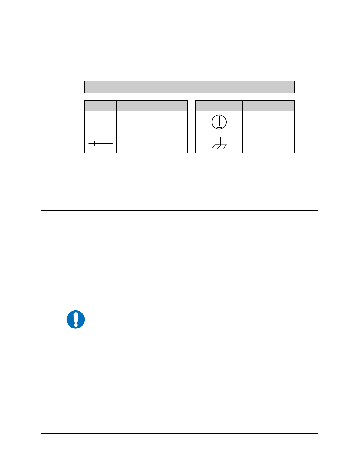
International Symbols
Symbol Definition Symbol Definition
~
Alternating Current
Fuse
Telecommunications Terminal Equipment Directive
In accordance with the Telecommunications Terminal Equipment Directive 91/263/EEC, this
equipment should not be directly connected to the Public Telecommunications Network.
EMC (Electromagnetic Compatibility)
In accordance with European Directive 89/336/EEC, the CDM-625 Modem has been shown, by
independent testing, to comply with the following standards:
Emissions: EN 55022 Class B - Limits and methods of measurement of radio
interference characteristics of Information Technology Equipment.
(Also tested to FCC Part 15 Class B)
Immunity: EN 50082 Part 1 - Generic immunity standard, Part 1: Domestic,
commercial and light industrial environment.
Protective Earth
Chassis Ground
To ensure that the Modem continues to comply with these standards,
IMPORTANT
observe the following instructions:
• Connections to the transmit and receive IF ports (BNC female connectors) should be
made using a good quality coaxial cable - for example RG58/U (50Ω or RG59/U (75Ω).
• All 'D' type connectors attached to the rear panel must have back-shells that provide
continuous metallic shielding. Cable with a continuous outer shield (either foil or braid,
or both) must be used, and the shield must be bonded to the back-shell.
• The equipment must be operated with its cover on at all times. If it becomes necessary to
remove the cover, the user should ensure that the cover is correctly re-fitted before
normal operation commences.
xvi
Page 19

CDM-550T Satellite Modem Revision 3
Preface MN/CDM550T.IOM
Warrant y Policy
Comtech EF Data products are warranted against defects in material and workmanship
for a period of two years from the date of shipment. During the warranty period,
Comtech EF Data will, at its option, repair or replace products that prove to be defective.
For equipment under warranty, the owner is responsible for freight to Comtech EF Data
and all related customs, taxes, tariffs, insurance, etc. Comtech EF Data is responsible for
the freight charges only for return of the equipment from the factory to the owner.
Comtech EF Data will return the equipment by the same method (i.e., Air, Express,
Surface) as the equipment was sent to Comtech EF Data.
All equipment returned for warranty repair must have a valid RMA number issued prior
to return and be marked clearly on the return packaging. Comtech EF Data strongly
recommends all equipment be returned in its original packaging.
Comtech EF Data Corporation’s obligations under this warranty are limited to repair or
replacement of failed parts, and the return shipment to the buyer of the repaired or
replaced parts.
Limitations of Warranty
The warranty does not apply to any part of a product that has been installed, altered,
repaired, or misused in any way that, in the opinion of Comtech EF Data Corporation,
would affect the reliability or detracts from the performance of any part of the product, or
is damaged as the result of use in a way or with equipment that had not been previously
approved by Comtech EF Data Corporation.
The warranty does not apply to any produ ct or pa rts thereof where th e serial number or the
serial number of any of its parts has been altered, defaced, or removed.
The warranty does not cover damage or loss incurred in transportation of the product.
The warranty does not cover replacement or repair necessitated by loss or damage from
any cause beyond the control of Comtech EF Data Corporation, such as lightning or other
natural and weather related events or wartime environments.
The warranty does not cover any labor involved in the removal and or reinstallation of
warranted equipment or parts on site, or any labor required to diagnose the necessity for
repair or replacement.
The warranty excludes any responsibility by Comtech EF Data Corporation for incidental or
consequential damages arising from the use of the equipment or products, or for any inability
to use them either separate from or in combination with any other equipment or products.
xvii
Page 20

CDM-550T Satellite Modem Revision 3
Preface MN/CDM550T.IOM
A fixed charge established for each product will be imposed for all equipment returned
for warranty repair where Comtech EF Data Corporation cannot identify the cause of the
reported failure.
Exclusive Remedies
Comtech EF Data Corporation’s warranty, as stated is in lieu of all other warranties,
expressed, implied, or statutory, including those of merchantability and fitness for a
particular purpose. The buyer shall pass on to any purchaser, lessee, or other user of
Comtech EF Data Corporation’s products, the aforementioned warranty, and shall
indemnify and hold harmless Comtech EF Data Corporation from any claims or liability
of such purchaser, lessee, or user based upon allegations that the buyer, its agents, or
employees have made additional warranties or representations as to product preference or
use.
The remedies provided herein are the buyer’s sole and exclusive remedies. Comtech EF
Data shall not be liable for any direct, indirect, special, incidental, or consequential
damages, whether based on contract, tort, or any other legal theory.
xviii
Page 21

1.1 Overview
The CDM-550T Satellite Modem, shown here in Figure 1-1, is a very low-cost Closed Network
Satellite Modem, intended for both Very Small Aperture Terminal (VSAT) and hub applications.
It offers variable data rates from 2.4 to 2048kbps, in BPSK, QPSK and Offset QPSK modes. Both
Viterbi and Sequential Forward Error Correction (FEC) are provided as standard.
The modem is compact, 1RU high and 12 inches deep, and consumes only 18 watts. It has a front
panel Vacuum Fluorescent Display (VFD) display and keypad for local configuration and
control, although it can be fully remote-controlled.
Chapter 1. INTRODUCTION
Figure 1-1. CDM-550T
1.2 Standar d Fe atures
IF port impedance is selectable from the front panel. Users may choose between the universal
standard of 50Ω or the less frequently used 75Ω. The CDM-550T offers both impedances in the
same unit as a standard feature.
To facilitate network management, the CDM-550T incorporates EDMAC, an acronym for
Embedded Distant-end Monitor And Control (EDMAC). In this mode, an additional 5%
overhead is combined with the traffic data, (1.5% in Turbo BPSK modes) which permits M&C
information to be added (transparently to the user), allowing access to the distant-end modem.
This mode does not require any additional cabling at either the local or distant-end Modems access to EDMAC is via the standard M&C control port. Full monitor and control is possible, and
importantly, the on/off status of the carrier at the distant-end carrier can be controlled.
1–1
Page 22

CDM-550T Satellite Modem Revision 3
Introduction MN/CDM550T.IOM
1.2.1 AUPC
An important innovation in the CDM-550T is the addition of Automatic Uplink Power Control
(AUPC). This feature enables the modem to automatically adjust its output power to maintain the
Eb/No of the remote end of the satellite link constant. This provides protection against rain
fading, a particularly severe problem with Ku-band links.
To accomplish this, the framed (EDMAC) mode of operation must be used, and the distant end
modem constantly sends back information about the demodulator Eb/No using reserved bytes in
the overhead structure. Using the Eb/No, the local modem then adjusts its output power, and
hence, a closed-loop feedback system is created over the satellite link.
A benefit of this feature is that whenever framed operation is selected, the remote demodulator’s
Eb/No can be viewed from the front panel display of the local modem. Note that both EDMAC
and AUPC can be used simultaneously.
1.2.2 Software
The internal software is both powerful and flexible, permitting storage and retrieval of up to 10
different modem configurations. The modem uses ‘flash memory’ technology internally, and new
firmware can be uploaded to the unit from an external PC. This simplifies software upgrading,
and updates can now be sent via the Internet, E-mail, or on disk. The upgrade can be performed
without opening the unit, by simply connecting the modem to the serial port of a computer.
1.2.3 Verification
The unit includes many test modes and loopbacks for rapid verification of the correct functioning
of the unit. Of particular note is the IF loopback, which permits the user to perform a quick
diagnostic test without having to disturb external cabling. During the loopback, all of the receive
configuration parameters are temporarily changed to match those of the transmit side. When
normal operation is again selected, all of the previous values are restored.
1.2.4 Data Interfaces
The CDM-550T includes, as standard, a universal data interface which eliminates the need to
exchange interface cards for different applications. The interfaces offered include:
• RS-422 (RS-530) DCE
• V.35 DCE
• Synchronous RS-232 DCE
• Asynchronous RS-232 (at data rates up to 56 kbaud)
• X.21 DTE and DCE
1–2
Page 23

CDM-550T Satellite Modem Revision 3
Introduction MN/CDM550T.IOM
1.3 Options
As an external option, a G.703 interface (Comtech EF Data Model Number CIC-50), operating at
T1 (1544 kbps) and E1 (2048 kbps) is available.
Two optional Forward Error Correction (FEC) Codecs can be supplied.
• The first, a Reed-Solomon (R-S) Codec (a plug-in daughter card, field upgradeable),
significantly enhances the bit error performance of the modem.
• The second is the Comtech EF Data Turbo Product Codec (TPC), representing a very
significant development in the area of FEC. Like the R-S Codec, it is a plug-in daughter
card, field upgradeable. It provides the best level of BER improvement currently
available, and in Rate 3/4 QPSK mode, simultaneously conserves bandwidth.
1.4 Compatibility
For 1:1 applications the CDM-550T is supported by a low-cost external switch, the
CRS-100. For Hub applications, the CDM-550T is supported by a low-cost 1:N switch, the CRS-
200. Its fast acquisition time makes it attractive for both demand-assigned and fixed-assigned
SCPC applications.
The CDM-550T is a companion product for the Comtech EF Data line of Radio Frequncy (RF)
Transceivers. The Modem incorporates an Frequency Shift Keyong (FSK) serial link that can be
activated on the Receive Intermediate Frequency (IF) port for the purpose of communicating with
a Transceiver, if connected. In this manner, a user may monitor, configure, and control the
Transceiver, using the front panel display and keypad of the Modem. The EDMAC channel may
also be used to convey Monitor & Control (M&C) data to a Transceiver at the distant end of a
satellite link, if it is connected to a CDM-550T.
The CDM-550T is fully backwards-compatible with the Comtech EF Data CDM-500 and
CDM-550 modems.
1.5 Manual Release Notes
Revision 3 incorporates the following MN/CDM550T.IOM updates:
• Update Customer Service and Warranty information (see Preface)
• Update FEC End-to-End Processing Delay specifications table (see Sect. 7.5.1)
• Update FEC Turbo Product CODEC Figure 7-7
• Update Demodulator Specification table, Turbo Product CODEC BER (see Sect. 14.2)
1–3
Page 24

CDM-550T Satellite Modem Revision 3
Introduction MN/CDM550T.IOM
Firmware update notes:
• Version 1.33 has added a new timed Diversity Switch operating mode.
(Note: Please contact CEFD Customer Service for further infomation on the operation
and use of this mode.)
• Version 1.24 has added new Turbo Code Rate – Rate 1/2 QPSK
• Version 1.20 firmware has added KST-2000 ODU capability
• Version 1.19 firmware has added new Turbo Code Rate – Rate 3/4 OQPSK
• Version 1.15 firmware has added two new Turbo Code Rates - Rate 21/44 and Rate 5/16
- both operating in BPSK only.
(Note: If you do not have Version 1.15 or higher installed in your CDM-550T, contact
the factory for a free upgrade)
• Version 1.10 firmware incorporates the following features:
1. Link performance statistics logging. A second log has been added (independent of the
stored events log), where the user can choose to record link performance statistics at
regular intervals. Parameters which are recorded include minimum and average
values of Eb/No, and maximum and average values of Transmit power level increase,
if AUPC is being used.
2. Receive/Transmit Inhibit (RTI) which permits the user to stop a remote site from
bringing up its transmit carrier until its demodulator is correctly locked.
1–4
Page 25

Chapter 2. INSTALLATION
2.1 Unpacking and Inspection
Inspect shipping containers for damage. If shipping containers are damaged, keep them until the
contents of the shipment have been carefully inspected and checked for normal operation.
Remove the packing list from the outside of the shipping carton. Open the carton and remove the
contents, checking the contents against the packing list. Verify completeness of the shipment and
that the unit functions correctly. If damage is evident, contact the carrier and Comtech EF Data
immediately and submit a damage report. Keep all shipping materials for the carrier's inspection.
If the unit needs to be returned to Comtech EF Data, please use the original shipping container.
2.2 Mounting
If the CDM-550T is to be mounted in a rack, ensure that there is adequate clearance for ventilation.
The CDM-550T does not include a cooling fan, so care must be taken that too many units are not
mounted on top of each other. The limit is four units, and then a blank 1U panel must be inserted to
allow sufficient airflow around the units. In rack systems where there is high heat dissipation,
forced air cooling must be provided by top or bottom mounted fans or blowers. Under no
circumstance should the highest internal rack temperature be allowed to exceed 50°C (122°F).
2.2.1 Leading Particulars
Parameter Requirement
Dimensions 1U, 12 inches (30.5 cm) Deep
Weight 7 lbs (3.2 kg) maximum
The unit is not designed to have rack slides mounted to the side of the chassis. However, some
method of support within the rack should be employed, such as rack shelves. If there is any
question, consult the Comtech EF Data, Customer Support department.
2–1
Page 26

CDM-550T Satellite Modem Revision 3
Installation MN/CDM550T.IOM
2.3 Configuration
There are no internal jumpers to configure, no interface cards to install, and no other options to
install. All configuration is carried out entirely in software. The unit should first be configured
locally, using the front panel keypad and display. The unit will ship with a default 64 kbps,
QPSK, Rate 1/2 configuration. Refer to the ‘FRONT PANEL OPERATION’ section for details
on how to fully configure the unit for the desired operating parameters.
The auto-sensing AC power supply does not require any adjustments. Simply plug in the supplied
line cord, and turn on the switch on the rear panel.
2.4 Select Internal IF Loop
Correct operation of the unit may be verified rapidly, without the need for externally connected
equipment. From the top level menu, select TEST, then IF LOOP (refer to the ‘FRONT
PANEL OPERATION’ section). The demod should synchronize, and the GREEN RECEIVE
TRAFFIC LED should illuminate. If the unit does not pass this test, call the factory for
assistance.
2.5 Connect External Cables
Having verified correct operation in IF loop, enter the desired configuration, and proceed to
connect all external cables. If difficulties occur, please call the factory for assistance.
Please note that the modulator gives an output power level in the range 0 to -20 dBm, and the
demodulator expects to see a signal in the range -30 to -60 dBm.
FREQUENTLY ASKED QUESTION - Optimum input level:
Adjust the input level to the demodulator so that the AGC value
displayed on the RX PARAMETERS screen reads between 90
and 95.
2–2
Page 27

Chapter 3. FUNCTIONAL
DESCRIPTION
The CDM-550T has two fundamentally different types of interface – Data and Intermediate
Frequency (IF):
• The data interface is a bi-directional path which connects with the customer’s equipment
(assumed to be the Digital Test Equipment [DTE]) and the modem (assumed to be the
Digital Circuit Equipment [DCE]).
• The IF interface provides a bi-directional link with the satellite via the uplink and
downlink equipment.
Transmit Data
1. Tx data is received by the terrestrial interface where line receivers convert the clock and
data signals to Complementary Metal-Oxide Semiconductor (CMOS) levels for
processing.
2. A small First In – First Out (FIFO) follows the terrestrial interface to facilitate the various
clocking and framing options.
3. If framing is enabled, the Tx clock and data output from the FIFO pass through the
framer, where the EDMAC data is added to the main data.
4. Otherwise, the clock and data are passed directly to the FEC encoder.
5. In the FEC encoder, the data is differentially encoded, scrambled, and then
convolutionally encoded.
6. Following the encoder, the data is fed to the Tx digital filters, which perform spectral
shaping on the data signals.
7. The resultant I and Q signals are then fed to the QPSK/BPSK modulator.
8. The carrier is generated by a frequency synthesizer, and the I and Q signals directly
modulate this carrier to produce an IF output signal.
3–1
Page 28

CDM-550T Satellite Modem Revision 3
Functional Description MN/CDM550T.IOM
Receive Data
1. Rx IF signal is first translated to a fixed IF frequency, using a frequency synthesizer.
2. An Automatic Gain Control (AGC) circuit maintains the composite level within the IF
bandwidth constant over a limited range.
3. Following this, the signal is sampled by a high-speed (flash) Analog-to-Digital (A/D)
converter.
4. All processing beyond this conversion is purely digital.
5. The signal is translated down to near zero frequency by a complex mix, and then is
processed by a digital Costas Loop, which performs the functions of Nyquist filtering,
carrier recovery, and bit-timing recovery.
6. The resultant demodulated signal is fed, in soft decision form, to the FEC decoder
(Viterbi, Sequential or Turbo, and Reed-Solomon, if installed).
7. After decoding, the recovered clock and data pass to the de-framer (if EDMAC is
enabled) where the overhead information is removed.
8. Following this, the data passes to the Plesiochronous/Doppler buffer, which has a
programmable size, or may be bypassed.
9. From here, the Rx clock and data signals are routed to the terrestrial interface, and are
passed to the externally connected DTE equipment.
3–2
Page 29
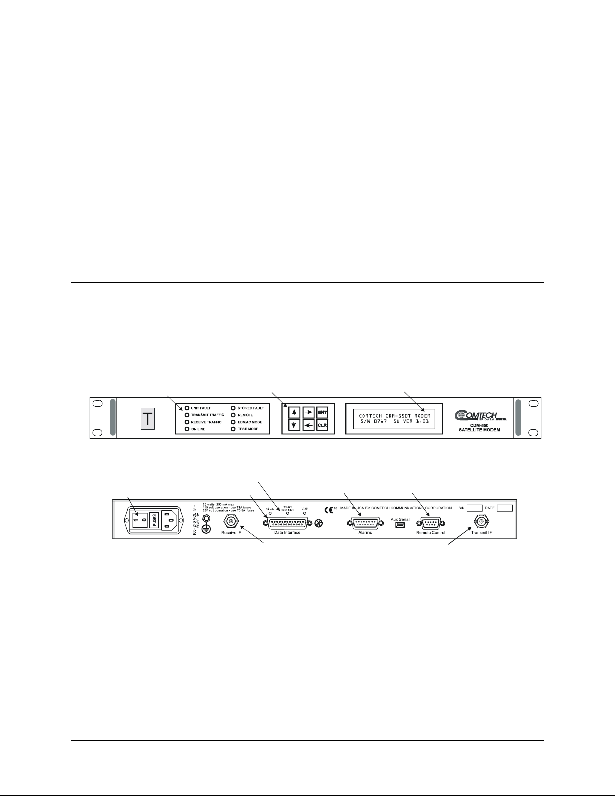
4.1 Overview
The CDM-550T is constructed as a 1RU high rack-mounting chassis, which can be free-standing,
if desired. Rack handles at the front facilitate removal from and placement into a rack. Figure 4-1
shows the front and rear panels of the modem.
Chapter 4. PHYSICAL
DESCRIPTION
On/Off Switch
dicatorsLED In
25 Pin ‘D’ Ty pe Femal e
Figure 4-1 CDM-550T Front and Rear Panels
LED Indicators
Keypad
CDM-550T Front Panel
15 Pin ‘D’ Type Male
BNC Female
CDM-550T Rear Panel
Vacuum Fluorescent Display
9 Pin ‘D’ Typ e Male
BNC Female
4–1
Page 30

CDM-550T Satellite Modem Revision 3
Physical Description MN/CDM550T.IOM
4.2 Front Panel
On the front panel of the unit is the Vacuum Fluorescent Display (VFD), keypad, and eight Light
Emitting Diode (LED) indicators. The user enters data via the keypad, and messages are
displayed on the VFD. The LEDs indicate, in a summary fashion, the status of the unit.
The VFD is an active display showing two lines, each of 24 characters. It produces a blue light,
the brightness of which can be controlled by the user. It has greatly superior viewing
characteristics compared to a Liquid Crystal Display (LCD), and does not suffer problems of
viewing angle or contrast.
The keypad comprises six individual keyswitches, mounted directly behind a fully sealed
membrane overlay. They have a positive ‘click’ action, which provides the user with tactile
feedback. These six switches are identified as [↑] [↓] [←] [→], ENT (Enter) and CLR (Clear).
The functions of these keys are described in Chapter 6. FRONT PANEL OPERATION.
There are eight LED indicators. The functions of these indicators are shown in Table 4-1:
Table 4-1. Front Panel LED Indicators
LED Color Condition
Unit
Status
Transmit
Traffic
Receive
Traffic
On line
Stored
Event
Remote
EDMAC
Mode
Test Mode
Red A Unit Fault exists (Example: PSU fault)
Orange No Unit Faults, but a Traffic Fault exists
Green No Unit Faults, or Traffic Faults
Green No Tx Traffic Faults
Off
Green No Rx Traffic Faults (demod and Viterbi decoder are locked, everything is OK)
Off An Rx Traffic fault exists (the demod may still be OK)
Green The Unit is On Line, and carrying traffic
Off
Orange
Off There are no Stored Events
Orange The Unit is in Remote Mode - local monitoring is possible, but no local control
Off The Unit is in Local Mode - remote monitoring is possible, but no remote control
Orange Framing on, EDMAC on, and unit defined as Slave
Off Either no EDMAC, EDMAC Master, or Transparent mode is selected
Orange A Test Mode is selected (Example: IF Loopback)
Off There is no Test Mode currently selected
A Tx Traffic fault exists OR the Tx Carrier is in OFF state
The Unit is Off Line (standby) - forced by externally connected 1:1 or 1:N
redundancy system
There is a Stored Event in the log, which can be viewed from the front panel, or
retrieved via the remote control interface
In general, the Alarm relay state will reflect the state of the Front Panel LEDs.
For instance, if the Unit Status LED is RED, the Unit Alarm relay will be active,
IMPORTANT
etc. The one exception is the Transmit Traffic relay. This will only be activated if
a Transmit Traffic Fault exists – it does not reflect the state of the TX carrier.
4–2
Page 31

CDM-550T Satellite Modem Revision 3
Physical Description MN/CDM550T.IOM
4.3 Rear Panel
External cables are attached to connectors on the rear panel of the CDM-550T. These comprise
the IEC line input connector, the Rx and Tx IF connectors, the Data connector, Alarms
connector, Remote Control connector, and Auxiliary Serial connector.
The IEC line input connector contains the ON/OFF switch for the unit. It is also fitted with two
fuses - one each for line and neutral connections (or L1, L2, where appropriate). These are
contained within the body of the connector, behind a small plastic flap.
• For 230 volt AC operation, use T0.5A, (slow-blow) 20mm fuses.
• For 115 volt AC operation, use T1A fuses, (slow-blow) 20mm fuses.
For continued operator safety, always replace the fuses with the correct type
IMPORTANT
The IF port connectors are both a 50Ω BNC female type. 75Ω cable connectors (male) will have
no problem mating with this 50Ω type.
The Data connector is a 25 pin ‘D’ type female (DB25-F). This connector conforms to the RS530 pinout, which allows for connection of different electrical standards, including RS-422, V.35,
and RS-232. Note that it is the responsibility of the user to provide the appropriate cables to
connect to this RS-530 connector. A shielded 25 pin ‘D’ type provides a very solid solution to
EMC problems, unlike the sometimes used V.35 Winchester connector. The pinout for the RS530 connector is provided in the next section.
Note that the currently selected interface type is indicated by a small orange LED which is
located immediately above the connector. This provides an easy visual indication to anyone
mating a connector at the rear of the unit.
The Alarms connector is a 15 pin 'D' type male (DB15-M). This provides the user with access to
the Form-C relay contacts which indicate the fault status of the unit. These are typically
connected to an external fault monitoring system, often found in satellite earth stations. In
addition, the receive I and Q demodulator samples are provided on this connector. Connecting
these signals to an oscilloscope in X,Y mode will provide the receive signal constellation
diagram, which is a useful diagnostic aid. A pin is also provided which can mute the transmit
carrier. This requires that the pin be shorted to ground, or a TTL ‘low’, or an RS-232 ‘high’
signal be applied.
As an aid to antenna pointing, or for driving step-track equipment, an analog AGC signal is
provided on a pin of this connector. The demodulator incorporates three separate AGC control
loops, one of which is analog, and two of which are entirely digital. The first of these loops keeps
the signal level constant at the input to the flash A/D converter in the final IF stage. This loop has
a limited dynamic range (~ 35 dB) and operates on the total power within the IF bandwidth
(which varies with data rate). The characteristics of this control voltage are shown at the rear of
the specifications section.
and rating.
4–3
Page 32

CDM-550T Satellite Modem Revision 3
Physical Description MN/CDM550T.IOM
The pinout details for this connector are provided in the next chapter.
The Remote Control connector is a 9 pin 'D' type female (DB9-M). Access is provided to remote
control ports of the modem, both RS-232 and RS-485. The pinout details for this connector are
provided in the next section.
The Auxiliary Serial connector is an HE1402 3 pin header. A suitable mate for this connector is
AMP part number 281838-3, with three crimp pins, AMP part number 182734-2, also required.
This is an additional RS-232 serial port, which is only used when the modem is part of a 1:1 pair,
at the distant-end of a link, and when both units are defined as EDMAC slaves. The pinout details
for this connector are provided in the next section.
4–4
Page 33

Chapter 5. REAR PANEL
CONNECTOR PINOUTS
5.1 Connector Overview
The rear panel connectors, shown in Figure 5-1, provide all necessary external connections
between the modem and other equipment. This chapter summarizes the connectors provided on
the rear panel interface.
Figure 5-1. CDM-550T Rear Panel Connectors
5–1
Page 34
CDM-550T Satellite Modem Revision 3
Rear Panel Connector Pinouts MN/CDM550T.IOM
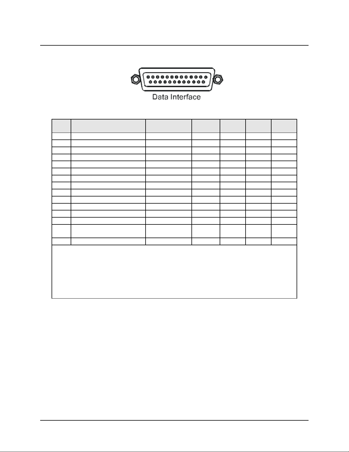
5.2 Data Interface Connector, DB-25F
Table 5-1. Data Connector, 25-pin Type ‘D’ Female
Pin Generic Signal description Direction
1 Shield - Shield FG AN 101
2 Transmit Data A DTE to Modem SD A SD A BA 103
3 Receive Data A Modem to DTE RD A RD A BB 104
7 Signal Ground - SG SG AB 102
8 Receiver Ready A Modem to DTE RR A RLSD * CF 109
9 Receive Clock B Modem to DTE RT B SCR B - 115
10 Receiver Ready B Modem to DTE RR B - - 109
11 Transmit Clock B DTE to Modem TT B SCTE B - 113
12 Internal Transmit Clock B Modem to DTE ST B SCT B - 114
14 Transmit Data B DTE to Modem SD B SD B - 103
15 Internal Transmit Clock A Modem to DTE ST A SCT A DB 114
16 Receive Data B Modem to DTE RD B RD B - 104
17 Receive Clock A Modem to DTE RT A SCR A DD 115
23
24 Transmit Clock A DTE to Modem TT A SCTE A DA 113
NOTES:
• Receiver ready is an RS-232-level control signal on a V.35 interface
• DO NOT connect signals to pins which are not shown - these pins are reserved for use by the
• ‘B’ signal lines are not used for RS-232 applications
• For X.21 operation, use the RS-422 pins, but ignore Receive Clock if the Modem is DTE, and ignore
External Carrier Off
(RS-232 ‘1' or TTL ‘low’ )
redundancy system
Transmit clocks if the Modem is DCE
DTE to Modem - - - -
RS-422/
RS-530
V.35 RS-232
Circuit
No.
5–2
Page 35

CDM-550T Satellite Modem Revision 3
Rear Panel Connector Pinouts MN/CDM550T.IOM
5.3 Alarms Connector, DB-15M
Table 5-2. Alarms Connector, 15-pin Type ‘D’ Male
Pin Description
1 Ground
2 Receive AGC voltage
3 Receive Q sample (for constellation display)
4 Unit Fault Relay - Common
5 Unit Fault Relay - Normally Open
6 Transmit Traffic Relay - Normally Closed
7 Receive Traffic Relay - Common
8 Receive Traffic Relay - Normally Open
9 External Carrier Off input
10 Not Used
11 Receiv e I sample (for constellation display)
12 Unit Fault Relay - Normally Closed
13 Transmit Traffic Relay - Common
14 Transmit Traffic Relay - Normally Open
15 Receive Traffic Relay - Normally Closed
Note: ‘Normally Open’ refers to the NON-FAIL state
5.4 Remote Control Connector, DB-9M
Table 5-3. Remote Control Connector, 9-pin Type ‘D’ Male
Pin Description
1 Ground
2 RS-232 Transmit Data (Out)
3 RS-232 Receive Data (In)
4 Reserved
5 Ground
6 RS-485 Receive Data B (In)
7 RS-485 Receive Data A (In)
8 RS-485 Transmit Data B (Out)
9 RS-485 Transmit Data A (Out)
5–3
Page 36

CDM-550T Satellite Modem Revision 3
Rear Panel Connector Pinouts MN/CDM550T.IOM
5.5 Auxiliary Serial Connector, HE1402 3-Pin Header
Table 5-4 Auxiliary Serial Connector, HE1402 3-Pin Header
Pin Description
1 RS-232 Transmit Data (Output)
2 Ground
3 RS-232 Receive Data (Input)
5.5.1 Pin Numbering
Facing the rear panel, Pin 1 is on the right-hand side :
• • •
Pin 1
5–4
Page 37

6.1 Introduction
Chapter 6. FRONT PANEL
OPERATION
LED Indicators
The user can fully control and monitor the operation of the CDM-550T from the front panel,
using the keypad and display. Nested menus are used, which display all available options, and
prompt the user to carry out a required action.
The display has two lines each of 24 characters. On most menu screens, the user will observe a
flashing solid block cursor, which blinks at a once-per-second rate. This indicates the currently
selected item, digit, or field. Where this solid block cursor would obscure the item being edited
(for example, a numeric field) the cursor will automatically change to an underline cursor.
If the user were to display the same screen for weeks at a time, the display could become ‘burnt’
with this image. To prevent this, the unit has a ‘screen saver’ feature which will activate after 1
hour. The top line of the display will show the Circuit ID (which can be entered by the user) and
the bottom line will show the circuit Eb/No value (if the demod is locked) followed by ‘Press any
key....’. The message moves from right to left across the screen, then wraps around. Pressing any
key will restore the previous screen.
Keypad
Figure 6-1. CDM-550T Front Panel
Vacuum Fluorescent Display
6–1
Page 38

CDM-550T Satellite Modem Revision 3
Front Panel Operation MN/CDM550T.IOM
6.1.1 Front Panel Keypad
The keypad has six keys, the functions of which are described as follows:
Figure 6-2. Keypad
[→]
[←]
[↑]
[↓]
[ENT]
[CLR]
IMPORTANT
(Left Arrow) Moves the cursor to the right, when it is displayed
(Right Arrow) Moves the cursor to the left, when it is displayed
(Up Arrow) Used for editing the value at the current cursor position, if appropriate.
If this is a numeric field, this will increment the value.
(Down Arrow) Used for editing the value at the current cursor position, if
appropriate. If this is a numeric field, this will decrement the value.
(ENTER) Used to accept an edited entry. Most menus prompt the user to press this
key, by displaying the text (Press ENTER), (ENTER) or (ENT). This results in the
entry being accepted, and the user is then returned to the previous menu.
(CLEAR) Used to escape from the current operation and return to the previous
menu.
The keypad has an auto-repeat feature. If a key is held down for more
than 1 second, the key action will repeat, automatically, at the rate of
15 keystrokes per second. This is particularly useful when editing
numeric fields, with many digits, such as frequency or data rate.
6–2
Page 39

CDM-550T Satellite Modem Revision 3
Front Panel Operation MN/CDM550T.IOM
6.2 Menu Trees
Figure 6-3 shows the menu structure of the CDM-550T. The ‘level’ of the menu (how far down
into the structure) is indicated by how far the screen is indented from the left.
Figure 6-3. Principle Menu Trees
The detailed screens and menus are described in the following paragraphs.
6–3
Page 40

CDM-550T Satellite Modem Revision 3
Front Panel Operation MN/CDM550T.IOM
6.2.1 Opening Screen
COMTECH CDM-550T MODEM
S/N 123456789 S/W 1.24
This screen is displayed whenever power is first applied to the unit. Pressing any key will take the
user to the top level selection screen:
6.2.2 SELECT: (Top level) Menu
SELECT: CONFIG TEST INFO
MONIT STORE/LD UTIL ODU
The user is presented with the following choices:
CONFIG
TEST
INFO
MONIT
STORE/LD
UTIL
ODU
(Configuration) This menu branch permits the user to fully configure the unit.
This menu branch permits the user invoke one of several test modes
(loopbacks, for example).
(Information) This menu branch permits the user to view information on the
unit, without having to go into configuration screens.
(Monitor) This menu branch permits the user to monitor the alarm status of the
unit, to view the log of stored events, and to display the Receive Parameters
screen.
(Store/Load) This menu branch permits the user to store and to retrieve up to
10 different modem configurations.
(Utility) This menu branch permits the user to perform miscellaneous
functions, such as setting the Real-time clock, adjusting the display
brightness, etc.
(Outdoor Unit) This permits the user to monitor and control a Comtech RF
Transceiver, if connected. See Appenidx D. KST-2000A FSK (ODU)
REMOTE OPERATION for full information about this submenu.
6–4
Page 41

CDM-550T Satellite Modem Revision 3
Front Panel Operation MN/CDM550T.IOM
6.2.3 SELECT: CONFIG
CONFIG: ALL TX RX FRAME
INTFC REMCONT MASK IMPED
The sub-branches available are:
This menu sub-branch permits the user to completely configure the unit,
ALL
TX
being prompted, step by step, to make choices, or edit data. This is highly
recommended for new users, as it will clearly demonstrate all the parameters
which need to be set.
(Transmit) This menu sub-branch permits the user to define, on a parameterby-parameter basis, the transmit configuration of the unit. These menu subbranches would be used if the user wished to change, for example, just the
Transmit frequency.
RX
FRAME
INTFC
REMCONT
MASK
IMPED
(Receive) This menu sub-branch permits the user to define, on a parameterby-parameter basis, the receive configuration of the unit. These menu subbranches would be used if the user wished to change, for example, just the
receive data rate.
This menu sub-branch permits the user to define if the unit should operate in
a transparent mode (no framing) or in a framed mode. In the framed mode,
an overhead of 5% is added to the rate transmitted over the satellite so that
M&C information may be passed to the distant end.
(Interface) This menu sub-branch permits the user to define which electrical
interface type is active at the data connector.
(Remote Control) This menu sub-branch permits the user to define whether
the unit is being controlled locally, or remotely.
NOTE: The unit may be monitored over the remote control bus at any time.
When in Local mode, however, configuration parameters may only be
changed through the front panel. Conversely, when in Remote mode, the unit
may be monitored from the front panel, but configuration parameters may
only be changed via the remote control bus.
This menu sub-branch permits the user to mask certain traffic alarms, which
may cause problems to the user. As an example, certain multiplexers use ‘all
ones’ as an idle pattern. However, by convention, the ‘all ones’ condition is
taken to be the Alarm Indication Signal (AIS). The CDM-550T monitors for
the AIS condition, and if desired, this alarm may be masked.
(Impedance) This menu sub-branch permits the user to define the
impedance at the IF connectors, either 50 or 75 Ω.
6–5
Page 42

CDM-550T Satellite Modem Revision 3
Front Panel Operation MN/CDM550T.IOM
6.2.3.1 (CONFIG:) TX (Transmit)
TX: MOD FREQ DATA FEC
ON/OFF PWR SCRAM CLK TSI
The sub-branches available are:
6.2.3.1.1 (CONFIG: TX) MOD (Modulation)
SELECT TX MODULATION:
BPSK QPSK OQPSK (ENTER)
Select BPSK, QPSK, or Offset QPSK modulation, using the [←] [→] arrow keys, then press
ENTER.
Note: If a TURBO FEC option is selected, the modulation type will be automatically fixed, and
the user will be presented with a warning screen.
6.2.3.1.2 (CONFIG: TX) FREQ (Frequency)
EDIT TX FREQUENCY:
72.2345 MHz (PRESS ENT)
Edit the transmit frequency. This is accomplished by selecting the digit to be edited, using the
[←] [→] arrow keys. The value of the digit is then changed using the [↑] [↓] arrow keys. The
user should then press ENTER. The range of frequencies is from 52 to 88 MHz or 104 to 176
MHz (70 / 140 MHz factory option).
6–6
Page 43

CDM-550T Satellite Modem Revision 3
Front Panel Operation MN/CDM550T.IOM
6.2.3.1.3 (CONFIG: TX) DATA (Data Rate)
EDIT TX DATA RATE:
2048.000 kbps(PRESS ENT)
Edit the Tx data rate. This is accomplished by selecting the digit to be edited, using the [←] [→]
arrow keys. The value of the digit is then changed using the [↑] [↓] arrow keys. The user should
then press ENTER. The overall range of data rates is from 2.4 to 2048 kbps.
NOTE: The minimum and maximum data rates are dependent on modulation type and FEC
encoder rate. If the user changes the modulation or FEC, and the currently selected data rate is
then invalid, it will be adjusted automatically.
6.2.3.1.4 (CONFIG: TX) FEC TYPE (Forward Error Correction):
If either the Reed-Solomon Codec option or the Turbo Codec option are not installed, the
following menu will be displayed:
(CONFIG: TX, FEC)
SELECT FEC TYPE: VITERBI
SEQUENTIAL NONE (ENTER)
Select either Viterbi, Sequential, or None, using the [←] [→] arrow keys, then
press ENTER.
If the Reed-Solomon Codec option is installed, the following menu will be
displayed:
(CONFIG: TX, FEC)
SELECT FEC TYPE: VIT SEQ
VIT+RS SEQ+RS NONE (ENT)
Select Viterbi, Sequential, Viterbi + concatenated Reed-Solomon, Sequential +
concatenated Reed-Solomon, or None, using the [←] [→] arrow keys, then press
ENTER.
6–7
Page 44

CDM-550T Satellite Modem Revision 3
Front Panel Operation MN/CDM550T.IOM
If the Turbo Codec option is installed, the following menu will be displayed:
SELECT FEC TYPE: VITERBI
SEQ TURBO NONE (ENTER)
Select Viterbi, Sequential, Turbo or None, using the [←] [→] arrow keys, then
press ENTER.
(CONFIG: TX, FEC, RATE) FEC Rate
(Any FEC Type Except Turbo)
SELECT FEC ENCODER RATE:
1/2 3/4 7/8(PRESS ENT)
Select Rate 1/2, Rate 3/4 or Rate 7/8 encoding rate, using the [←] [→] arrow
keys, then press ENTER.
Note: If BPSK is selected, only Rate 1/2 is permitted. A warning screen appears
if this sub-branch is entered when in BPSK mode.
If Turbo is selected, the following sub-menu will be displayed:
TX TURBO:3/4(Q) 21/44(B)
5/16(B) 3/4(OQ)1/2(Q)(ENT)
(CONFIG: TX, FEC, RATE) FEC Rate (Turbo Only)
Select Rate 3/4 (QPSK), Rate 21/44 (BPSK ONLY) Rate 5/16 (BPSK ONLY),
Rate 3/4 (OQPSK), or Rate 1/2 (Q) encoding rate, using the [←] [→] arrow keys,
then press ENTER.
Turbo Rate 3/4 OQPSK
Incorporated by Version 1.19
Turbo Rate 1/2 QPSK
Note: For further details, see Section 7 - ‘FEC Options’.
6–8
Incorporated by Version 1.24
Page 45

CDM-550T Satellite Modem Revision 3
p
Front Panel Operation MN/CDM550T.IOM
6.2.3.1.5 (CONFIG: TX) ON/OFF
SELECT TX OUTPUT STATE:
ON OFF RTI (ENTER)
Select either ON, OFF, or RTI, using the [←] [→] arrow keys, then press ENTER.
RTI means RECEIVE/TRANSMIT INHIBIT. When selected, it will
revent the TX carrier from being transmitted, until the demodulator
IMPORTANT
To avoid the Tx Carrier from being turned off when the demodulator loses lock for a very short
period of time, the demodulator must be unlocked continuously for a period of 10 seconds before
the transmit carrier is inhibited. This time interval is fixed and the user cannot change it.
IMPORTANT
is locked.
Having this feature enabled does not affect the internal IF loopback
feature. But, be aware that if an external IF loopback is attempted
(connecting an external cable from the Tx IF output to the Rx IF
input), then this will NOT work! (The Tx carrier cannot turn on until
the demod is locked, and the demod cannot lock, because the TX
ouput is off. The net result is that the demod will not lock, and the
Tx carrier will not turn on. PLEASE USE THE RTI FEATURE WITH
EXTREME CARE!
(CONFIG: TX Æ PWR) MODE
OUTPUT POWER LEVEL MODE:
MANUAL AUPC (ENTER)
Select the output power level mode, either Manual or AUPC, then press ENTER.
If the user selects MANUAL, the following menu is displayed:
6–9
Page 46

CDM-550T Satellite Modem Revision 3
Front Panel Operation MN/CDM550T.IOM
(CONFIG: TX Æ PWR Æ MODE) MANUAL
EDIT OUTPUT POWER LEVEL:
-03.9 dBm (PRESS ENTER)
Edit the output power level, then press ENTER.
If the user selects AUPC, and ‘Framed’ mode is not selected, the following menu
is displayed:
(CONFIG: TX Æ PWR Æ MODE) AUPC
WARNING! AUTO UPLINK PWR
CONTROL NEEDS FRAMED MODE
Pressing either ENTER or CLEAR returns the user to the previous menu with
MANUAL selected.
If the user selects AUPC, and ‘Framed’ mode is selected, the following menu is
displayed:
(CONFIG: TX Æ PWR Æ MODE) AUPC
TARGET EbNo MAX RANGE
ALARM DEMOD-UNLOCK(ENT)
Select either TARGET EbNo, MAX RANGE, ALARM or DEMOD-UNLOCK.
The user should then press ENTER.
6–10
Page 47

CDM-550T Satellite Modem Revision 3
Front Panel Operation MN/CDM550T.IOM
(CONFIG: TX Æ PWR Æ MODE Æ AUPC) TARGET EbNo
Edit the target Eb/No of the remote modem. Default value is 3.0 dB, an
d upper
EDIT TARGET MIN EbNo OF
REMOTE MODEM:9.9dB (ENT)
limit is 9.9 dB. The user should then press ENTER.
(CONFIG: TX Æ PWR Æ MODE Æ AUPC) MAX RANGE
EDIT MAX PERMITTED POWER
INCREASE: 1dB (ENTER)
Edit the maximum permitted increase in power level when in AUPC mode.
Default value is 1dB, and upper limit is 9 dB. Then press ENTER.
(CONFIG: TX Æ PWR Æ MODE Æ AUPC) ALARM
SELECT ACTION AT MAXIMUM
TX POWER: NONE TX ALARM
Select the action that will occur if the AUPC causes the maximum output power
level to be reached, either NONE or TX ALARM. Then press ENTER.
(CONFIG: TX Æ PWR Æ MODE Æ AUPC) DEMOD-UNLOCK
ACTION WHEN REMOTE DEMOD
UNLOCKS: NOM-PWR MAX-PWR
elect the action that will occur if the remote demod is unlocked. The choices
S
are: NOM-PWR (Nominal Power), where the ouput level will revert to the
nominal power level set under MANUAL, or MAX-PWR, (Maximum Power),
where the ouput level will change to the maximum permitted. The user should
then press ENTER.
6–11
Page 48

CDM-550T Satellite Modem Revision 3
Front Panel Operation MN/CDM550T.IOM
6.2.3.1.6 (CONFIG: TX) SCRAM (Scrambling)
Select either ON or OFF, using the [←] [→] arrow keys, then press ENTER.
SELECT TX SCRAMBLING:
OFF ON (PRESS ENTER)
When Transparent mode is selected, a V.35 scrambler is used. In Framed or Reed-Solomon
modes, a frame synchronised scrambler is used.
6.2.3.1.7 (CONFIG: TX) CLK (Clocking)
SELECT TX CLOCKING MODE:
INT EXT LOOP-TIMED (ENT)
Select INT (Internal), EXT (External) or LOOP-TIMED, using the LEFT/RIGHT arrow keys,
then press ENTER.
INTERNAL
indicates that the CDM-550T will supply a clock to the DTE, which is derived
from its internal high-stability source.
EXTERNAL
LOOP-TIMED
indicates that the CDM-550T expects to receive a clock from the DTE, to
which the unit can phase-lock its internal circuits.
indicates that the transmit timing source should be the receive clock, from
the direction of the satellite. This is a useful mode, in that no external
connection needs to be made in this mode. If the demodulator loses lock, or
if there is no receive signal present, the internal clock is substituted. Note
also that this mode will work even with asymmetric RX and TX data rates.
6.2.3.1.8 (CONFIG: TX) TSI (Transmit Spectral Invert)
SELECT TRANSMIT SPECTRAL
INVERSION: OFF ON(ENTER)
Select either OFF or ON, using the [←] [→] arrow keys, then press ENTER.
When in the ON position, and QPSK is selected, the transmit spectrum is inverted (which is the
same as reversing the direction of phase rotation in the modulator). In BPSK, the time-order of
bits out of the FEC encoder is reversed, to make the modem compatible with certain other
manufacturer’s modems.
6–12
Page 49

CDM-550T Satellite Modem Revision 3
Front Panel Operation MN/CDM550T.IOM
6.2.3.2 (CONFIG:) RX (Receive)
RX: MOD FRQ DATA FEC ACQ
DESCRAM CLK BUF RSI EbNo
The sub-branches available are:
6.2.3.2.1 (CONFIG: RX) MOD (Modulation)
SELECT RX MODULATION:
BPSK QPSK OQPSK (ENTER)
Select BPSK, QPSK, or Offset QPSK demodulation, using the [←] [→] arrow keys, then press
ENTER. (Note: if a TURBO FEC option is selected, the demodulation type will be automatically
fixed, and the user will be presented with a warning screen.)
6.2.3.2.2 (CONFIG: RX) FRQ (Frequency)
EDIT RX FREQUENCY:
72.2345 MHz (PRESS ENT)
Edit the receive frequency. This is accomplished by selecting the digit to be edited, using the [←]
[→] arrow keys. The value of the digit is then changed using the [↑] [↓] arrow keys. The user
should then press ENTER. The range of frequencies is from 52 to 88 MHz or 104 to 176 MHz (70 /
140 MHz factory option).
6.2.3.2.3 (CONFIG: RX) DATA (Data Rate)
EDIT RX DATA RATE:
64.000 kbps (PRESS ENT)
Edit the Rx data rate. This is accomplished by selecting the digit to be edited, using the [←] [→]
arrow keys. The value of the digit is then changed using the [↑] [↓] arrow keys. The user should
then press ENTER. The overall range of data rates is from 2.4 to 2048 kbps.
6–13
Page 50

CDM-550T Satellite Modem Revision 3
Front Panel Operation MN/CDM550T.IOM
NOTE: The minimum and maximum data rates are dependent on modulation type and FEC
decoder rate. If the user changes the modulation or FEC, and the currently selected data rate is
then invalid, it will be adjusted automatically.
6.2.3.2.4 (CONFIG: RX) FEC TYPE (Forward Error Correction):
If either the Reed-Solomon Codec option or the Turbo Codec option are not installed, the
following menu will be displayed:
SELECT FEC TYPE: VITERBI
SEQUENTIAL NONE (ENTER)
Select either Viterbi, Sequential, or None, using the [←] [→] arrow keys, then
press ENTER. However, if the Reed-Solomon Codec option is installed, the
following menu will be displayed:
SELECT FEC TYPE: VIT SEQ
VIT+RS SEQ+RS NONE (ENT)
Select Viterbi, Sequential, Viterbi + concatenated Reed-Solomon, Sequential +
concatenated Reed-Solomon, or None, using the [←] [→] arrow keys, then press
ENTER.
If the Turbo Codec option is installed, the following menu will be displayed:
SELECT FEC TYPE: VITERBI
SEQ TURBO NONE (ENTER)
Select Viterbi, Sequential, Turbo or None, using the [←] [→] arrow keys, then
press ENTER.
6–14
Page 51

CDM-550T Satellite Modem Revision 3
Front Panel Operation MN/CDM550T.IOM
(CONFIG: RX Æ FEC Æ RATE) FEC RATE
SELECT FEC ENCODER RATE:
1/2 3/4 7/8(PRESS ENT)
Select Rate 1/2, Rate 3/4 or Rate 7/8 encoding rate, using the [←] [→] arrow
keys, then press ENTER.
NOTE: If BPSK is selected, only Rate 1/2 is permitted. A warning screen will be
displayed if this sub-branch is entered when in BPSK mode.
If Turbo is selected, the following menu will be displayed:
(CONFIG: RX Æ FEC Æ RATE) FEC RATE (TURBO ONLY)
RX TURBO: 3/4(Q) 21/44(B)
5/16(B) 3/4(OQ) 1/2(Q)(ENT)
Select Rate 3/4 (QPSK), Rate 21/44 (BPSK ONLY) Rate 5/16 (BPSK ONLY) ,
Rate 3/4 (OQPSK), or Rate 1/2 (QPSK) decoding rate, using the [←] [→] arrow
keys, then press ENTER.
Turbo Rate 3/4 OQPSK
Turbo Rate 1/2 QPSK
Note: For further details, see Section 7 - ‘FEC Options’.
Incorporated by Version 1.19
Incorporated by Version 1.24
6.2.3.2.5 (CONFIG: RX) ACQ (Acquisition swee p range)
EDIT RX ACQ SWEEP RANGE:
+/- 25 kHz (PRESS ENTER)
Edit the acquisition sweep range of the demodulator. This is accomplished by selecting the digit
to be edited, using the [←] [→] arrow keys). The value of the digit is then changed using the [↑]
[↓] arrow keys. The user should then press ENTER.
The range varies from ± 1 kHz to ± 30 kHz.
6–15
Page 52

CDM-550T Satellite Modem Revision 3
Front Panel Operation MN/CDM550T.IOM
The value entered here determines the amount of frequency uncertainty the demodulator will
sweep over in order to find and lock to an incoming carrier. When operating at low bit rates, large
values of sweep range (compared to the data rate) will cause excessively long acquisition times.
For example: selecting ± 30 kHz with a data rate of 2.4 kbps, BPSK, will result in an average
acquisition time of around 5 minutes.
6.2.3.2.6 (CONFIG: RX) DESCRAM (Descrambler)
SELECT RX DE-SCRAMBLING:
ON OFF (PRESS ENTER)
Select either ON or OFF, using the [←] [→] arrow keys, then press ENTER.
When Transparent mode is selected, a V.35 descrambler is used. In Framed mode, a frame-synchronised
descrambler is used. It is recommended that scrambling/descrambling be used at all times.
(CONFIG: RX) CLK (Clocking)
SELECT RX CLOCKING MODE:
BUFFER ON OFF(PRESS ENT)
Select either OFF or ON, using the [←] [→] arrow keys, then press ENTER.
When OFF is selected, the Plesiochronous/Doppler buffer is disabled. The
receive clock will then be derived from the satellite signal, and will therefore be
subject to clock offsets relative to the local transmit clock, and a small amount
(< 5%) clock jitter, due to the demodulation bit-timing recovery process at low
values of Eb/No.
When ON is selected, the Plesiochronous/Doppler buffer is enabled. The input to
the buffer will be the signal from the satellite, with any clock offsets and jitter.
The output from the buffer will be derived from the local TRANSMIT clock. In
this way, the receive data will be perfectly synchronous with this local clock. The
CDM-550T can be operated with independent transmit receive and transmit data
rates. Even in this configuration, where RX data rate <> TX data rate, the output
clock for the buffer will be phase locked to the transmit clock. When the buffer is
enabled, the size of the buffer may be selected using the next menu:
6–16
Page 53

CDM-550T Satellite Modem Revision 3
Front Panel Operation MN/CDM550T.IOM
(CONFIG: RX) BUF (Buffer size)
EDIT RX BUFFER SIZE:
+/-4096 BITS (PRESS ENT)
Edit the size, in bits of the Plesiochronous/Doppler Buffer. The value is changed
using the [↑] [↓] arrow keys. The user should then press ENTER. Values of
± 256, 512, 1024, 2048 and 4096 bits are possible. If the buffer is disabled, a
warning message will be displayed if this screen is entered.
6.2.3.2.7 (CONFIG: RX) RSI (Receive spectral inversion)
SELECT RECEIVE SPECTRAL
INVERSION: OFF ON(ENTER)
Select either OFF or ON, using the [←] [→] arrow keys, then press ENTER.
This should normally be in the OFF position. When in the ON position, the receive spectrum is
inverted (which is the same as reversing the direction of phase rotation in the demodulator).
Note: In BPSK mode, the demodulator will automatically synchronize to either the normal timeordering of bits FEC codeword pairs, or the inverted ordering used by certain other
manufacturers.
6.2.3.2.8 (CONFIG: RX) Eb/No (Eb/No Alarm)
EDIT Eb/No ALARM POINT:
2.0 dB (PRESS ENTER)
Edit the Eb/No alarm point. This is accomplished by selecting the digit to be edited, using the
[←] [→] arrow keys. The value of the digit is then changed using the [↑] [↓] arrow keys. The
user should then press ENTER.
The range of values is from 2.0 to 16.0 dB. The user may select a value here, and if the Eb/No
falls below this value, a receive traffic fault will be generated.
6–17
Page 54

CDM-550T Satellite Modem Revision 3
Front Panel Operation MN/CDM550T.IOM
6.2.3.2.9 (CONFIG:) FRAME (Framing Mode)
SELECT FRAMING MODE:
TRANSPARENT FRAMED (ENT)
The sub-branches available are:
6.2.3.2.10 (CONFIG: FRAME) TRANSPARENT
No framing is selected. No overhead is added, and the unit will be compatible with other
manufacturer’s equipment, when operating in a ‘standard’ configuration (IESS 308 filtering, V.35
scrambling, Viterbi).
Refer to Appendix C for details of the Async Overhead Mode
which was added in Software Version 1.19. This provides an
IMPORTANT
alternaive to the EDMAC modes described below.
6.2.3.2.11 (CONFIG: FRAME) FRAMED
SELECT FRAMING OPTION:
EDMAC-OFF EDMAC-ON (ENT)
Select either EDMAC-OFF or EDMAC-ON, using the [←] [→] arrow keys, then press ENTER.
EDMAC is enabled or disabled in this sub-menu.
• If EDMAC-OFF is selected then none of the EDMAC features are available, even
though framing will still be enabled.
• If EDMAC-ON is selected, the user is further prompted to select whether the unit is
an EDMAC master, or an EDMAC slave:
6–18
Page 55

CDM-550T Satellite Modem Revision 3
Front Panel Operation MN/CDM550T.IOM
6.2.3.2.12 (CONFIG: FRAME Æ FRAMED) EDMAC-ON
SELECT EDMAC MODE:
MASTER SLAVE (ENTER)
Select either MASTER or SLAVE, using the [←] [→] arrow keys, then press ENTER.
An EDMAC MASTER is a unit which is local to the M&C computer, and which passes
messages, via the overhead, to a distant-end modem.
An EDMAC SLAVE is a unit which is not local to the M&C computer, which is at the distant-
end of a satellite link. If MASTER is selected then the following sub-menu is displayed:
(CONFIG: FRAMEÆ FRAMEDÆ ON) EDMAC MASTER
EDIT DISTANT-END'S ADDR:
0240 (SEE HANDBOOK)(ENT)
Edit the address of the distant-end modem which this unit will pass messages to.
This is accomplished by selecting the digit to be edited, using the [←] [→] arrow
keys. The value of the digit is then changed using the [↑] [↓] arrow keys. The
user should then press ENTER.
There is a restriction on values which can be entered here - they may only be in
increments of 10. This is automatically taken care of - the user may not edit the
last digit of the address. This has been implemented so that a single MASTER
may pass messages for up to 10 devices at the distant end. The valid range of
addresses is from 10 to 9990.
But if SLAVE is selected, then the following sub-menu is displayed:
(CONFIG: FRAMEÆ FRAMED Æ ON) EDMAC SLAVE
EDIT THIS UNIT'S ADDRESS
0245 (SEE HANDBOOK)(ENT)
Edit the address of this SLAVE unit. This is accomplished by selecting the digit
to be edited, using the [←] [→] arrow keys. The value of the digit is then
changed using the [↑] [↓] arrow keys. The user should then press ENTER. The
valid range of addresses is from 1 to 9999, although ‘base 10' values will be
automatically skipped.
6–19
Page 56

CDM-550T Satellite Modem Revision 3
Front Panel Operation MN/CDM550T.IOM
Remember that this is a unit which is intended to be located at the distant-end of
a link, and will therefore be under the control of a MASTER at the other end.
This is the equivalent of putting the unit into Remote Control mode - no local
control is possible.
6.2.3.3 (CONFIG:) INTFC (Interface)
DATA INTERFACE: RS422
V.35 RS232 (ENTER)
Select RS-422 (RS-530), V.35, or RS-232, using the [←] [→] arrow keys, then press ENTER.
Refer to Section 10 for details on using the RS-232 interface in asynchronous mode.
6.2.3.4 (CONFIG:) REMCONT (Remote control)
SELECT REMOTE CONTROL:
LOCAL REMOTE (PRESS ENT)
Select LOCAL or REMOTE using the [←] [→] arrow keys, then press ENTER.
6.2.3.4.1 (CONFIG: LOCAL)
If LOCAL is selected then remote control will be disabled. Remote monitoring is still possible.
6.2.3.4.2 (CONFIG: REMOTE)
If REMOTE is selected then the following sub-menus will be displayed:
If the unit has not been defined as an EDMAC SLAVE then:
REMOTE CONTROL: BAUDRATE
INTERFACE (PRESS ENTER)
Select BAUDRATE or INTERFACE, using the [←] [→] arrow keys, then press ENTER.
6–20
Page 57

CDM-550T Satellite Modem Revision 3
Front Panel Operation MN/CDM550T.IOM
6.2.3.4.3 (CONFIG: REMOTE Æ BAUD)
If BAUD RATE is selected:
EDIT LOCAL BUS BAUDRATE:
19200 BAUD (PRESS ENTER)
Edit the baud rate of the remote control bus, connected locally to the M&C computer. The value
is changed using the [↑] [↓] arrow keys. The user should then press ENTER.
Values of 300, 1200, 2400, 4800, 9600 and 19200 baud are possible.
Note: The asynchronous character format is FIXED at: 8 data bits, 1 stop bit, no parity (8-N-1).
6.2.3.4.4 (CONFIG: REMOTE Æ INTFC)
If INTERFACE is selected:
ELECT. INTERFACE: RS232
RS485-2W RS485-4W (ENT)
Select RS-232, RS-485 (2-wire), or RS-485 (4-wire), using the [←] [→] arrow keys, then press
ENTER.
At this point the user will be further prompted to enter the bus address.
In RS-232 mode the bus address is fixed at 0, and the following screen will be displayed:
(CONFIG: REM Æ INTFC Æ ADDR) RS232 BUS ADDRESS
IN RS232 MODE THE BUS
ADDRESS IS FIXED AT 0000
However, if either RS-485 mode is selected, the user will be further prompted:
6–21
Page 58

CDM-550T Satellite Modem Revision 3
Front Panel Operation MN/CDM550T.IOM
(CONFIG: REM Æ INTFC Æ ADDR) RS485 BUS ADDRESS:
EDIT UNIT'S BUS ADDRESS:
0245 (PRESS ENTER)
Edit the RS-485 bus address of this unit. This is accomplished by selecting the
digit to be edited, using the [←] [→] arrow keys. The value of the digit is then
changed using the [↑] [↓]arrow keys. The user should then press ENTER. The
valid range of addresses is from 1 to 9999.
6.2.3.5 (CONFIG:) MASK (Alarm mask)
ALARM MASK: AGC Eb/No
RX-AIS BUF-SLIP TX-AIS
Select AGC, Eb/No, RX-AIS, BUF-SLIP, or TX-AIS, using the [←] [→] arrow keys, then press
ENTER.
One of the following sub-menus will be displayed:
6.2.3.5.1 (CONFIG: MASK) AGC
SELECT AGC ALARM MASK:
ACTIVE MASKED(PRESS ENT)
Select either ACTIVE or MASKED, using the [←] [→] arrow keys, then press ENTER.
If the user selects ACTIVE, then a Receive Traffic fault will be generated whenever the
demodulator senses that the composite input level being applied will cause compression in the IF
stages, and hence degrade the performance of the demodulator.
If the user selects MASKED, no alarm will be generated.
6–22
Page 59

CDM-550T Satellite Modem Revision 3
Front Panel Operation MN/CDM550T.IOM
6.2.3.5.2 (CONFIG:MASK) Eb/No
SELECT Eb/No ALARM MASK:
ACTIVE MASKED(PRESS ENT)
Select either ACTIVE or MASKED, using the [←] [→] arrow keys, then press ENTER.
If the user selects ACTIVE, then a Receive Traffic fault will be generated whenever the
demodulator determines that the Eb/No of the received carrier has fallen below the threshold
defined under CONFIG: RX, Eb/No.
If the user selects MASKED, no alarm will be generated.
6.2.3.5.3 (CONFIG: MASK) RX-AIS
SEL RX-AIS ALARM MASK:
ACTIVE MASKED(PRESS ENT)
Select either ACTIVE or MASKED, using the [←] [→] arrow keys, then press ENTER.
If the user selects ACTIVE, then a Receive Traffic fault will be generated whenever the
demodulator senses that the ‘all 1’s” condition is present in the receive data.
If the user selects MASKED, no alarm will be generated.
6.2.3.5.4 (CONFIG: MASK) BUF-SLIP (Buffer slip)
SEL BUF-SLIP ALARM MASK:
ACTIVE MASKED(PRESS ENT)
Select either ACTIVE or MASKED, using the [←] [→] arrow keys, then press ENTER.
If the user selects ACTIVE, then a Receive Traffic fault will be generated whenever the receive
circuitry senses that the buffer has either underflowed, or overflowed.
If the user selects MASKED, no alarm will be generated.
6–23
Page 60

CDM-550T Satellite Modem Revision 3
Front Panel Operation MN/CDM550T.IOM
6.2.3.5.5 (CONFIG, MASK) TX-AIS
SEL TX-AIS ALARM MASK:
ACTIVE MASKED(PRESS ENT)
Select either ACTIVE or MASKED, using the [←] [→] arrow keys, then press ENTER.
If the user selects ACTIVE, then a Transmit Traffic fault will be generated whenever the transmit
circuitry senses that the ‘all 1’s” condition is present in the transmit data.
If the user selects MASKED, no alarm will be generated .
6.2.3.6 (CONFIG:) IMPED (IF impedance)
SELECT IF IMPEDANCE:
50 OHMS 75 OHMS (ENTER)
Select either 50 or 75 Ω, using the [←] [→] arrow keys, then press ENTER.
6–24
Page 61

CDM-550T Satellite Modem Revision 3
Front Panel Operation MN/CDM550T.IOM
6.2.4 SELECT: TEST
TEST: NORM TX-CW TX-1,0
IF] DIG] I/O] RF] (ENT)
Select NORM, TX-CW, TX-1,0, IF LOOP, DIG LOOP, I/O LOOP or RF LOOP, using
the [←] [→] arrow keys, then press ENTER.
This sub-menu permits the user to select the following test modes:
NORM
(Normal) This clears any test modes or loopbacks, and places the unit back
into an operational state.
TX-CW
TX-1,0
IF LOOP
DIG LOOP
I/O LOOP
RF LOOP
(Transmit CW) This is a test mode which forces the modulator to transmit a
pure carrier (unmodulated).
(Transmit an alternating 1,0,1,0 pattern) This is a test mode which forces the
modulator to transmit a carrier modulated with an alternating 1,0,1,0 pattern, at
the currently selected symbol rate. This causes two discrete spectral lines to
appear, spaced at +/- half the symbol rate, about the carrier frequency. This
mode is used to check the carrier suppression of the Modulator.
(IF Loopback) This test mode invokes an internal IF loop. This is a particularly
useful feature, as it permits the user to perform a quick diagnostic test without
having to disturb external cabling. Furthermore, all of the receive configuration
parameters are temporarily changed to match those of the transmit side. When
NORMAL is again selected, all of the previous values are restored.
(Digital Loopback) This test mode invokes a digital loopback, which loops data
at the output of the digital FIR filter on the transmit side, back into the Viterbi
decoder on the receive side. This tests all of the interface, transmit baseband
circuits, FEC encoder, FEC decoder, and buffer.
(Inward/Outward loopback) This test mode invokes two distinct loopbacks. The
first of these is the inward loop, which takes data being received from the
satellite direction, and passes it directly to the modulator. Simultaneously, the
outward loop is invoked, whereby data being fed to the transmit data interface
is routed directly back out of the receive data interface.
(RF Loopback) This test mode is almost identical to the IF loop mode. All of the
receive configuration parameters are temporarily changed to match those of
the transmit side, however, no internal connection is made. This is useful for
performing a satelite loopback. When NORMAL is again selected, all of the
previous values are restored.
The IF LOOP, DIG LOOP and I/O LOOP modes are illustrated in Figure 6-4.
6–25
Page 62

CDM-550T Satellite Modem Revision 3
Front Panel Operation MN/CDM550T.IOM
Figure 6-4. Loopback Modes
6–26
Page 63

CDM-550T Satellite Modem Revision 3
Front Panel Operation MN/CDM550T.IOM
6.2.5 SELECT: INFO (Information)
INFO:ID TX RX BUFF EDMAC
REMCONT MASK MISC(ENTER)
Select ID, TX, RX, BUFF, EDMAC, REMCONT, MASK, or MISC using the [←] [→] arrow
keys, then press ENTER.
These screens display information on the current configuration of the unit. Depending on the
choice selected, one of the following screens will be displayed:
6.2.5.1 (INFO) ID (Circuit ID)
CIRCUIT ID: (ENTER)
THIS IS A TEST MESSAGE
This displays the user-defined Circuit ID string, which is entered via the UTIL, ID screen. To
return to the previous menu, press ENTER.
6.2.5.2 (INFO) TX (Transmit information)
Tx:140.0000 2048.000 VIT
Q R1/2 S LOP -20.0 ON I
The information displayed here is as follows:
Top line:
Transmit Frequency and Data Rate
FEC Encoder type (VIT = Viterbi, SEQ = Sequential, VRS=Viterbi + ReedSolomon, SRS=Sequential + Reed Solomon, TUR = Turbo, UNC = uncoded)
Bottom line:
Modulation type (Q = QPSK, O= OQPSK, B = BPSK)
Code Rate (shows blank in uncoded mode)
Scrambler state (S = Scrambler on, N = Scrambler off)
Clocking Mode (INT = internal, EXT = external, LOP = loop)
Output power level
Transmit output state (ON = on , OFF = off, EOF = external off)
TSI state (I = Transmit Spectral Inversion on, N = off)
6–27
Page 64

CDM-550T Satellite Modem Revision 3
Front Panel Operation MN/CDM550T.IOM
6.2.5.3 (INFO) RX (Receive information)
Rx: 70.0000 512.000 SEQ
B R3/4 D BUFF +/-23k I
The information displayed here is as follows:
Top line:
Receive Frequency
Receive Data Rate
FEC Decoder type (VIT = Viterbi, SEQ = Sequential, VRS=Viterbi + ReedSolomon, SRS=Sequential + Reed Solomon, TUR = Turbo, UNC = uncoded)
Bottom line:
Demodulation type (Q = QPSK, O= OQPSK, B = BPSK)
Code Rate (shows blank in uncoded mode)
Descrambler state (D = Descrambler on, N = off)
Clocking Mode
Demod Sweep Acquisition range
RSI state (I = Receive Spectral Inversion on, N = off)
6.2.5.4 (INFO) BUFF (Buffer information)
BUFFER: ENABLED (TX=RX)
SIZE: +/-4096 BITS
This displays if the buffer is enabled or disabled, shows the exact clocking mode (TX=RX, or
TX<> RX), and the buffer size. Pressing ENTER takes the user back to the previous menu.
6.2.5.5 (INFO) EDMAC (Framing and EDMAC information)
FRAMING: ON
EDMAC MODE: ON (SLAVE)
This screen shows the framing mode, EDMAC mode, and shows if the unit is an EDMAC
MASTER or SLAVE. Pressing ENTER takes the user back to the previous menu.
6–28
Page 65

CDM-550T Satellite Modem Revision 3
Front Panel Operation MN/CDM550T.IOM
6.2.5.6 (INFO) REMCONT (Remote Control information)
REM-CONTROL:ON RS485-4W
ADDRESS: 0001 19200 BAUD
This screen shows if the unit is in LOCAL or REMOTE mode, and gives details of the electrical
interface type selected, the unit’s address, and the baud rate selected. Pressing ENTER takes the
user back to the previous menu.
6.2.5.7 (INFO) MASK (Alarm mask information)
ALARMS MASKED:
RX-AIS TX-AIS
This shows, in the same format as the CONFIG: MASK sub menu, which alarms are currently
masked. If an alarm is not masked, a blank is displayed in the relevant screen position.
6.2.5.8 (INFO) MISC (Miscellaneous information)
MISC: IF-LOOP 50 OHMS
1:1 LINK IDLE ONLINE
This screen shows the following:
Test mode
IF impedance
1:1 link status - if the CRS-100 1:1 module is being used, this shows the status of
the serial link between the two units.
Redundancy status - either online or standby (1:1 or 1:N)
Pressing ENTER takes the user back to the previous menu.
6–29
Page 66

CDM-550T Satellite Modem Revision 3
Front Panel Operation MN/CDM550T.IOM
6.2.6 SELECT: MONIT (Monitor)
MONITOR:ALARMS RX-PARAMS
STORED-EVENTS STATS AUPC
Select ALARMS, RX-PARAMS, STORED EVENTS, STATS, or AUPC or using the [←] [→]
arrow keys, then press ENTER.
If the user selects ALARMS, the following sub-menu is displayed:
6.2.6.1 (MONIT :) ALARMS
LIVE ALARMS: UNIT
RECEIVE TRANSMIT
Select UNIT, RECEIVE, or TRANSMIT using the [←] [→] arrow keys, then press ENTER.
Depending on the choice selected, one of the following menus will be displayed:
6.2.6.1.1 (MONIT: ALARMS) UNIT (Unit alarms)
UNIT FAULT: -12 VOLT PSU
IS UNDER-VOLTAGE
The screen will indicate if there are any Unit Faults. If not, it will display ‘NONE’. Pressing
ENTER takes the user back to the previous menu.
6.2.6.1.2 (MONIT: ALARMS) RECEIVE (Receive alarms)
RX TRAFFIC: AGC ALARM
REDUCE COMPOSITE I/P LVL
The screen will indicate if there are any Receive Traffic Faults. If not, it will display ‘NONE’.
Pressing ENTER takes the user back to the previous menu.
6–30
Page 67

CDM-550T Satellite Modem Revision 3
Front Panel Operation MN/CDM550T.IOM
6.2.6.1.3 (MONIT: ALARMS) TRANSMIT (Transmit alarms)
TX TRAFFIC: NO CLOCK
DETECTED FROM INTERFACE
The screen will indicate if there are any Transmit Traffic Faults. If not, it will display ‘NONE’.
Pressing ENTER takes the user back to the previous menu.
If the user selects RX-PARAMS, the following sub-menu is displayed:
6.2.6.2 (MONIT:) RX-PARAMS (Receive Parameters)
RX:EbNo=05.7dB dF=+11.7k
BER=3.4E-9 BUF=50 AGC=24
If the demodulator is locked, this screen shows the following:
This shows the value of Eb/No calculated by the demodulator. The value
Eb/No
dF
BER
BUF
AGC
referred to here is the energy per information bit (Ebi), divided by the noise
spectral density (No).
The frequency offset of the received carrier, in kHz, with a displayed
resolution of 100 Hz.
This is an estimate of the corrected BER.
(Buffer fill state) This shows the fill state (in percent), of the receive Buffer.
After a reset, it will read 50. A value <50 indicates that the buffer is
emptying, and >50 indicates that it is filling.
A number between 0 and 99 indicating the gain setting of the coarse AGC
loop in the demod. It has a limited dynamic range, and should not be taken
as an accurate measurement of signal level.
If the demodulator is not locked, this screen shows the message ‘DEMODULATOR NOT
LOCKED’. Pressing ENTER or CLEAR will take the user back to the previous menu.
6–31
Page 68

CDM-550T Satellite Modem Revision 3
Front Panel Operation MN/CDM550T.IOM
If the user selects STORED EVENTS, the following sub-menu is displayed:
6.2.6.3 (MONIT:) STORED EVENTS
STORED EVENTS: VIEW
CLEAR ALL (PRESS ENTER)
Select VIEW or CLEAR ALL, using the LEFT/RIGHT arrow keys, then press
ENTER. If the user selects VIEW, the following screen is displayed:
6.2.6.3.1 (MONIT: EVENTS) VIEW
LOG23: 30/11/97 10:37:32
FT - DEMOD LOCK (UP/DWN)
The user may scroll backwards or forwards through the entries in the event log,
using the [↑] [↓] arrow keys. Pressing ENTER or CLEAR will take the user back
to the previous menu. The event log can store up to 100 events. When a fault
condition occurs, it is time-stamped and put into the log. Similarly, when the
fault condition clears, this is also recorded, as shown below:
LOG24: 30/11/97 10:37:35
OK - DEMOD LOCK (UP/DWN)
If the user selects CLEAR ALL, the event log is cleared, and the user is taken
directly back to the previous menu. However, if there are faults present on the
unit at this time, they will be re-time-stamped, and new log entries will be
generated.
Note: In accordance with international convention, the date is shown in
DAY-MONTH-YEAR format.
If the user selects STATS, the following sub-menu is displayed:
6–32
Page 69

CDM-550T Satellite Modem Revision 3
Front Panel Operation MN/CDM550T.IOM
6.2.6.3.2 (MONIT:) STATS (Link Statisics)
STA198:02/11/00 10:37:32
16.0,16.0,9.0,9.0(UP/DN)
Select VIEW, CLEAR, or CONFIGURE, using the [←] [→] arrow keys, then press ENTER.
If the user selects VIEW, the following screen is displayed:
(MONIT: STATS) VIEW
LINK STATISTICS: VIEW
CLEAR CONFIGURE (ENTER)
The user may scroll backwards or forwards through the entries in the statistics
log, using the [↑] [↓] arrow keys. Pressing ENTER or CLEAR will take the user
back to the previous menu. The event log can store up to 250 events.
The top line of the display indicates the log entry number, and the time and date
of the entry. Note that in accordance with international convention, the date is
shown in DAY-MONTH-YEAR format.
The bottom line of the display shows the statistics data which has been measured
and recorded.
The meaning and format of the numbers is as follows:
Minimum Eb/No, Average Eb/No, Maximum TPLI, Average TPLI
(where TPLI means Transmit Power Level increase, if AUPC is enabled).
The user defines a measurement interval (see MONITOR, STATS,
CONFIGURE) and during this interval, Eb/No and TPLI are observed, at a one
second rate. At the end of this period, the average Eb/No is calculated and
recorded, and the minimum value seen in the interval. Similarly, the average
TPLI is calculated, along with the highest value seen in the interval.
Notes: If the demod has lost lock during the measurement interval, the minimum
Eb/No will show ‘LOSS’ rather than indicate a value. However, the average
value (while the demod was locked) will still be calculated and shown. If, on the
other hand, the demodulator has been unlocked for the entire measurement
6–33
Page 70

CDM-550T Satellite Modem Revision 3
Front Panel Operation MN/CDM550T.IOM
interval, the average Eb/No will also show ‘LOSS’. (The display will show
‘LOSS,LOSS’.)
• If the measured values are greater than, or equal to 16.0 dB, the display
will show 16.0 dB.
• If AUPC is not enabled, the values of maximum and average TPLI will
both show ‘0.0'.
Examples:
08.0,13.5,2.5,1.8 means:
Minimum Eb/No observed in the measurement interval = 8.0 dB
Average Eb/No observed in the measurement interval = 13.5 dB
Maximum TPLI observed in the measurement interval = 2.5 dB
Average TPLI observed in the measurement interval = 1.8 dB
LOSS,04.5,0.0,0.0 means:
There was a loss of demod lock during the measurement interval
Average Eb/No observed in the measurement interval = 4.5 dB
Maximum TPLI observed in the measurement interval = 0 dB
Average TPLI observed in the measurement interval = 0 dB
(Which indicates no AUPC activity, or that AUPC is disabled.)
If the user selects CLEAR, the statistics log is cleared, and the user is taken
directly back to the previous menu.
If the users selects CONFIGURE, the following sub-menu is displayed:
(MONIT: STATS) CONFIGURE
LOGGING INTERVAL:90 MINS
(SET 00 TO DISABLE)(ENT)
The user is prompted to enter the logging interval (the period of time over which
the statistics will be measured), using the [↑] [↓] arrow keys, then press ENTER.
Setting this to a value of 00 disables the feature (no logging).
The user can choose 10, 20, 30, 40, 50, 60, 70, 80, or 90 minutes.
If AUPC is selected, and the modem is not in Framed mode, the following submenu is displayed:
6–34
Page 71

CDM-550T Satellite Modem Revision 3
Front Panel Operation MN/CDM550T.IOM
6.2.6.4 (MONITOR) AUPC
FRAMING NOT ENABLED!
(PRESS ENTER)
If AUPC is selected, and the modem is in Framed mode, the following sub-menu is displayed:
AUPC: REMOTE EbNo=14.0dB
TX POWER INCREASE=2.2dB
The top line displays the value of Eb/No of the demodulator at the distant end of the satellite link.
The Eb/No will display UNLOCK if the remote demod is unlocked. The bottom line shows how
much the AUPC system has increased the output power. If AUPC is not enabled, the value of TX
POWER INCREASE will show as 0.0 dB.
6.2.7 SELECT: STORE/LD (Store/Load)
STORE/LOAD CONFIG:
STORE LOAD (PRESS ENTER)
Select STORE or LOAD using the LEFT/RIGHT arrow keys, then press ENTER.
These sub-menus permit the user to store or load up to 10 different modem configurations in the
non-volatile memory of the modem
Selecting STORE will display the following screen:
6.2.7.1 (STORE/LD) STORE
STORE CONFIGURATION TO
LOCATION: 10 (ENTER)
Select the location to store the current configuration to, using the [↑] [↓] arrow keys, then press
ENTER. Locations 1 through 10 are available.
6–35
Page 72

CDM-550T Satellite Modem Revision 3
Front Panel Operation MN/CDM550T.IOM
If the selected location does not contain a previously stored configuration, the following screen is
displayed:
YOUR CONFIGURATION HAS
BEEN STORED! (ENTER)
Pressing ENTER or CLEAR will take the user back to the previous menu.
If, however, the selected location contains a previously stored configuration, the
following screen is displayed:
WARNING! LOC 10 CONTAINS DATA!
OVERWRITE? NO YES
Select NO or YES using the [←] [→] arrow keys, then press ENTER.
Selecting YES will overwrite the existing configuration at the selected location.
Selecting LOAD will display the following screen:
6.2.7.2 (STORE/LD) LOAD
LOAD CONFIGURATION FROM
LOCATION: 10 (ENTER)
Select the location to load a configuration from, using the UP/DOWN arrow keys, then press
ENTER. Locations 1 through 10 are available.
If the selected location contains valid data, the following screen will be displayed:
THE NEW CONFIGURATION
HAS BEEN LOADED (ENTER)
Pressing ENTER or CLEAR will take the user back to the previous menu.
6–36
Page 73

CDM-550T Satellite Modem Revision 3
Front Panel Operation MN/CDM550T.IOM
If, however, the selected location does not contain valid data, the following screen will be
displayed:
WARNING! LOC 10 CONTAINS
NO DATA! (ENTER)
Pressing ENTER or CLEAR will take the user back to the previous menu.
6.2.8 SELECT: UTIL (Utility)
UTILITY: SET-RTC DISPLAY
MAN-1:1 RECENTER-BUF ID
Select SET-RTC, DISPLAY, MAN-1:1, RECENTER-BUF, or ID, using the [←] [→] arrow
keys, then press ENTER.
This sub-menu permits the user to select from a number of different utility functions, which are
described below:
6.2.8.1.1 (UTIL:) SET-RTC (Set real-time clock)
EDIT REAL TIME CLOCK:
12:00:00 24/04/98 (ENT)
Edit the time and date settings of the real-time clock. This is accomplished by selecting the digit
to be edited, using the [←] [→] arrow keys. The value of the digit is then changed using the [↑]
[↓] arrow keys. Note that in accordance with international convention, the date is shown in DAYMONTH-YEAR format. The user should then press ENTER.
6.2.8.2 (UTIL:) DISPLAY (Display brightness)
EDIT DISPLAY BRIGHTNESS:
100% (PRESS ENTER)
Edit the display brightness, using the [↑] [↓] arrow keys. The user should then press ENTER.
6–37
Page 74

CDM-550T Satellite Modem Revision 3
Front Panel Operation MN/CDM550T.IOM
6.2.8.3 (UTIL:) MAN-1:1 (Manual 1:1 switchover)
If the unit is part of a 1:1 redundant pair of modems, and this unit, is currently on-line, pressing
PRESS ENT TO FORCE THIS
UNIT TO STDBY (1:1 ONLY)
ENTER will cause the unit to switch to standby.
6.2.8.4 (UTIL:) RECENTER-BUF (Re-center buffer)
PRESS ENTER TO RE-CENTER
THE RECEIVE BUFFER
Pressing ENTER will cause a forced re-centering of the Plesiochronous/Doppler buffer.
6.2.8.5 (UTIL:) ID (Circuit ID)
EDIT CIRCUIT ID: (ENTER)
THIS IS A TEST MESSAGE
Edit the Circuit ID string, using the [←] [→] and [↑] [↓] arrow keys. Only the bottom line is
available (24 characters). The cursor selects the position on the bottom line ([←] [→]) and the
character is then edited ([↑] [↓]). The following characters are available:
Space ( ) * + - , . / 0-9 and A-Z.
When the user has composed the string, press ENTER.
6–38
Page 75

Chapter 7. FORWARD ERROR
7.1 Introduction
As standard, the CDM-550T Modem is equipped with two Forward Error Correction (FEC)
Decoders, Viterbi, and Sequential. The constraint lengths and encoding polynomials are
compatible with the vast majority of existing modems from other manufacturers, and Comtech EF
Data has performed compatibility testing to ensure inter-operability.
As an option, the CDM-550T may be fitted with two additional FEC devices. The first is a
concatenated Reed-Solomon Codec. This is always used in conjunction with, rather than instead
of, the main FEC method (Viterbi or Sequential). It comprises a small daughter card, and may be
fitted at the factory at the time of order, or may be added by the user at a later date. The second
option is Comtech EF Data’s Turbo Product Codec (TPC), which is an entirely stand-alone
method of FEC. This too is a small daughter card.
CORRECTION OPTIONS
7.2 Viterbi
The combination of convolutional coding and Viterbi decoding has become an almost universal
standard for satellite communications. The CDM-550T complies with the Intelsat IESS 308/309
standards for Viterbi decoding with a constraint length of seven. This is a de facto standard, even
in a closed network environment, which means almost guaranteed inter-operability with other
manufacturer’s equipment. It provides very useful levels of coding gain, and its short decoding
delay and error-burst characteristics make it particularly suitable for low data rate coded voice
applications. It has a short constraint length, fixed at 7, for all code rates. (The constraint length is
defined as the number of output symbols from the encoder which are affected by a single input
bit.) By choosing various coding rates (Rate 1/2, 3/4 or 7/8) the user can trade off coding gain for
bandwidth expansion. Rate 1/2 coding gives the best improvement in error rate, but doubles the
transmitted data rate, and hence doubles the occupied bandwidth of the signal. Rate 7/8 coding, at
the other extreme, provides the most modest improvement in performance, but only expands the
transmitted bandwidth by 14 %. A major advantage of the Viterbi decoding method is that the
performance is independent of data rate, and does not display a pronounced threshold effect (i.e.,
does not fail rapidly below a certain value of Eb/No). This is not true of the Sequential decoding
method, as explained in the next section.
7–1
Page 76

CDM-550T Satellite Modem Revision 3
A
Forward Error Correction Options MN/CDM550T.IOM
Note: In BPSK mode, the CDM-550T only permits a coding rate of 1/2. Because the method of
convolutional coding used with Viterbi, the encoder does not preserve the original data intact, and
is called non-systematic.
Table 7-1 Viterbi Decoding Summary
FOR AGAINST
Good BER performance - very useful coding gain. Higher coding gain possible with Sequential.
Almost universally used, with de facto standards
for constraint length and coding polynomials
Shortest decoding delay (~100 bits) of any FEC
scheme - good for coded voice.
Short constraint length produce small error bursts good for coded voice.
No pronounced threshold effect - fails gracefully.
Coding gain independent of data rate.
7.3 Sequential
Although the method of convolutional coding and Sequential decoding appear to be very similar
to the Viterbi method, there are some fundamental differences. To begin with, the convolutional
encoder is said to be systematic - it does not alter the input data, and the FEC overhead bits are
simply appended to the data. Furthermore, the constraint length, k, is much longer (Rate 1/2,
k=36. Rate 3/4, k= 63. Rate 7/8, k=87). This means that when the decoding process fails (that is,
when its capacity to correct errors is exceeded) it produces a burst of errors which is in multiples
of half the constraint length. An error distribution is produced which is markedly different to that
of a Viterbi decoder. This gives rise to a pronounced threshold effect. A Sequential decoder does
not fail gracefully - a reduction in Eb/No of just a few tenths of a dB can make the difference
between acceptable BER and a complete loss of synchronization. The decoding algorithm itself
(called the Fano algorithm) uses significantly more path memory (4 kbits in this case) than the
equivalent Viterbi decoder, giving rise to increased latency. Furthermore, a fixed computational
clock is used to process input symbols, and to search backwards and forwards in time to
determine the correct decoding path. At lower data rates there are sufficient number of
computational cycles per input symbol to permit the decoding process to perform optimally.
However, as the data rate increases, there are fewer cycles available, leading to a reduction in
coding gain. This is clearly illustrated in the performance curves which follow. For data rates
above ~1 Mbps, Viterbi should be considered the better alternative.
Table 7-2 Sequential Decoding Summary
FOR
Higher coding gain (1 -2 dB) at lower
data rates, compared to Viterbi.
Pronounced threshold effect - does not fail gracefully in
poor Eb/No conditions.
Higher processing delay than Viterbi
(~4 k bits) - not good for low-rate coded voice.
Coding gain varies with data rate - favors lower data
rates.
GAINST
7–2
Page 77

CDM-550T Satellite Modem Revision 3
gly
g
g
g
y
Forward Error Correction Options MN/CDM550T.IOM
7.4 Reed-Solomon Outer Codec (Option)
enough that the purpose of the concatenated
iven BER. Factors such as rain-fade
IMPORTANT
It cannot be emphasized stron
Reed-Solomon is to dramatically improve the BER performance of a link under
iven noise conditions. It should NOT be considered as a method to reduce the
link EIRP requirement to produce a
in, particularly at Ku-band, are extremely important, and reducing link
mar
EIRP can seriousl
degrade the availability of such a link.
The concatenation of an outer Reed-Solomon Codec with Viterbi decoder first became popular
when it was introduced by Intelsat in the early 1990's. It permits significant improvements in
error performance without significant bandwidth expansion. The coding overhead added by the
RS outer Codec is typically around 10%, which translates to a 0.4 dB power penalty for a given
link. Reed-Solomon codes are block codes (as opposed to Viterbi and Sequential, which are
convolutional), and in order to be processed correctly the data must be framed and de-framed.
Additionally, Reed-Solomon codes are limited in how well they can correct errors which occur in
bursts. This, unfortunately, is the nature of the uncorrected errors from both Viterbi and
Sequential decoders, which produce clusters of errors which are multiples of half the constraint
length. (This is particularly severe in the case of Sequential, where the constraint lengths are
considerably longer than Viterbi). For this reason, the data must be interleaved following RS
encoding, and is then de-interleaved prior to decoding. This ensures that a single burst of errors
leaving the Viterbi or Sequential decoder is spread out over a number of interleaving frames, so
errors entering the RS decoder do not exceed its capacity to correct those errors.
In the case of the CDM-550T, two R-S code rates are used. A 220,200 code is used in transparent
modes, and a 200,180 code is used in framed (EDMAC) modes. (220,200 means that data is put
into blocks of 220 bytes, of which 200 bytes are data, and 20 bytes are FEC overhead.) These two
codes were chosen because they fit well into Comtech EF Data’s clock generation scheme, and
they have almost identical coding gain. When Viterbi decoding is used as the primary FEC, an
interleaver depth of 4 is used. When Sequential decoding is used, an interleaver depth of 8 is
used. The increase in coding gain is at the expense of delay. The interleaving/de-interleaving
delay and the delay through the decoder itself can be as high as 25 kbits. At very low data rates,
this equates to several seconds, making it highly unsuitable for voice applications. Additionally,
the de-interleaver frame synchronization method can add significantly to the time taken for the
demodulator to declare acquisition.
A characteristic of concatenated R-S coding is the very pronounced threshold effect. For any
given modem design, there will be a threshold value of Eb/No below which the demodulator
cannot stay synchronized. This may be due to the carrier-recovery circuits, or the synchronization
threshold of the primary FEC device, or both. In the CDM-550T, and Rate 1/2 operation, this
threshold is around 4 dB Eb/No. Below this value, operation is not possible, but above this value,
the error performance of the concatenated R-S system produces exceptionally low error rates for a
very small increase in Eb/No.
Care should be taken not to operate the demodulator near its sync threshold.
Small fluctuations in Eb/No may cause total loss of the link, with the subsequent
CAUTION
need for the demodulator to re-acquire the signal.
7–3
Page 78

CDM-550T Satellite Modem Revision 3
A
Forward Error Correction Options MN/CDM550T.IOM
Table 7-3 Concatenated RS Coding Summary
FOR
Exceptionally good BER performance - several
orders of magnitude improvement in link BER
under given link conditions.
Very small additional bandwidth expansion
Easy field upgrade in
CDM-550T
7.5 Turbo Product Codec (Option)
Turbo coding is an FEC technique developed within the last few years, which delivers significant
performance improvements compared to more traditional techniques. Unlike the popular method
of concatenating a Reed Solomon codec with a primary FEC codec, Turbo Coding is an entirely
stand-alone method. It does not require the complex interleaving/de-interleaving of the R-S
approach, and consequently, decoding delays are significantly reduced - see below.
Two general classes of Turbo Codes have been developed, Turbo Convolutional Codes (TCC), and
Turbo Product Codes (TPC, a block coding technique). TCC suffers from an irreducible BER of
approximately 1 x 10⁻⁷, and consequently, a Reed-Solomon codec may be added in or de r to achie ve
an acceptably low BER. For delay-sensitive applications this may be unacceptable, and the
implementation complexity of the TCC approach is high. For these reasons Comtech EF Data has
chosen to implement an FEC codec based on TPC. A Turbo Product Code is a 2 or 3 dimensional
array of block co des. Encoding is rela tively straightforward, but decoding is a very complex process
requiring multiple iterations of processing for maximum performance to be achieved.
When Comtech EF Data first introduced the Turbo Coding option in the CDM-550T, only Rate
3/4 QPSK was offered.
• Firmware Version 1.19 has added Rate 3/4 OQPSK operation.
• Firmware Version 1.24 has added Rate 1/2 QPSK operation.
These are excellent choices for applications where maximum bandwidth efficiency is desired, in
combination with high coding gain.
• Firmware Version 1.15 (and later) introduced two further code rates - Rate 21/44
BPSK (very close to Rate 1/2) and Rate 5/16 BPSK (very close to Rate 1/3).
These two rates were developed to address an entirely different case, namely that of transmission
from very small antennas, with limited transmitter power. For a dish antenna, the gain is directly
proportional to its area, and the lower the gain, the less directional the antenna becomes. Thus, in
satellite transmission, even though the dish may be perfectly pointed at the desired satellite, if the
beamwidth is wide enough, adjacent satellites in the orbital arc will also be illuminated. This is a
potential source of interference, and for this reason the ITU (International Telecommunications
GAINST
Very pronounced threshold effect - does not fail
gracefully in poor Eb/No conditions. Additional
coding overhead actually degrades sync
threshold, and reduces link fade margin.
Significant processing delay (~25 kbits) - not
good for voice.
Adds to demod acquisition time.
7–4
Page 79

CDM-550T Satellite Modem Revision 3
Forward Error Correction Options MN/CDM550T.IOM
Union) place strict limits on the power spectral density (also referred to as flux density) of signals
arriving at adjacent satellites.
One obvious method to reduce the level is to spread the transmitted signal over as wide a bandwidth
as possible. In the past, this has sometimes been achieved using a Spread Spectrum modulation
format, but this has severe penalties as far as demodulator co mplexity is concerned. However, by
using BPSK modulation and high FEC code rates (up to Rate 1/3, for example) the power spectral
density may be reduced. Taking Rate 1/2 QPSK as a baseline, moving to Rate 5/16 BPSK Turbo
Product Coding gives an immediate reduction in power spectral density of 5.0 dB.
Furthermore, the increased coding gain of this FEC method allows a further reduction in
transmitter power. Using Rate 1/2 Viterbi with concatenated Reed-Solomon as a baseline
example, Rate 5/16 provides 1.5 - 2.0 dB improvement in coding gain. Putting these two factors
together yields an overall reduction in power spectral density of approximately 7.0 dB. This
simultaneously permits a smaller antenna, and reduced transmitter power. The disadvantage is the
increased spectral occupancy of the carrier, and it will depend on the particular satellite operator
to determine if this poses a severe economic problem.
When operating at these higher code rates (21/44 and 5/16), the demodulator is forced to operate
in a region where the Ebt/No (also referred to as Es/No) is negative - in other words, there is more
noise than signal. For this reason it is more difficult for the demodulator to accurately measure
the Eb/No, and so users may see more variation than normal when viewing the Eb/No on the RX
PARAMETERS screen, and when operating near threshold. This is most pronounced in the case
of Rate 5/16.One unexpected advantage of the TPC method is that, unlike concatenated ReedSolomon methods, there is no pronounced threshold effect. The demodulator and FEC codec can
stay locked down to very low values of Eb/No, but at this level the output BER becomes unusable
(around 1 x 10⁻²).
7.5.1 End-to-End Processing Delay
In many cases, FEC methods which provide increased coding gain do so at the expense of
increased processing delay. However, with TPC, this increase in delay is very modest. The table
below shows, for the CDM-550T, the processing delays for the major FEC types, including the
three TPC modes:
FEC Mode (64 kbps data rate) End-to-end delay, ms
Viterbi, Rate 1/2 12
Sequential, Rate 1/2 74
Viterbi Rate 1/2 + Reed Solomon 266
Sequential Rate 1/2 + Reed Solomon 522
Turbo Product Coding, Rate 3/4, QPSK/OQPSK 79
Turbo Product Coding, Rate 21/44, BPSK 64
Turbo Product Coding, Rate 5/16, BPSK 48
(Note that in all cases, the delay is inversely proportional to data rate, so for 128 kbps, the delay
values would be half of those shown above.)
7–5
Page 80

CDM-550T Satellite Modem Revision 3
Forward Error Correction Options MN/CDM550T.IOM
It can be clearly seen that the concatenated Reed-Solomon cases increase the delay very
significantly (due mainly to interleaving/de-interleaving), while the TPC cases yield delays which
are less than or equal to Sequential decoding.
FOR AGAINST
Exceptionally good BER performance - significant
improvement compared with every other FEC method in
use today
No pronounced threshold effect - fails gracefully
Exceptional bandwidth efficiency for Rate 3/4 QPSK -
40% less than Viterbi and concatenated Reed-Solomon
Coding gain independent of data rate (in this
implementation)
Low decoding delay
Easy field upgrade in CDM-550T
Nothing!
7.6 Uncoded Operation (No FEC)
There are occasions where a user may wish to operate a satellite link with no forward error
correction of any kind. For this reason, the CDM-550T offers this uncoded mode for all three
modulation types - BPSK, QPSK and OQPSK. However, the user should be aware of some of the
implications of using this approach.
PSK demodulators have two inherent undesirable features. The first of these is known as ‘phase
ambiguity’, and is due to the fact the demodulator does not have any absolute phase reference,
and in the process of carrier recovery, the demodulator can lock up in any of K phase states,
where K = 2 for BPSK, K = 4 for QPSK/OQPSK. Without the ability to resolve these ambiguous
states there would be a 1-in-2 chance that the data at the output of the demodulator would be
wrong, in the case of BPSK. For QPSK, the probability would be 3 in 4.
The problem is solved in the case of BPSK by differentially encoding the data prior to
transmission, and then performing the inverse decoding process. This is a very simple process,
but has the disadvantage that it doubles the receive BER. For every bit error the demodulator
produces, the differential decoder produces two.
The problem for QPSK is more complex, as there are 4 possible lock states, leading to 4
ambiguities. When FEC is employed, the lock state of the FEC decoder can be used to resolve
two of the four ambiguities, and the remaining two can be resolved using serial differential
encoding/decoding. However, when no FEC is being used, another scheme entirely must be used.
Therefore, in QPSK, a parallel differential encoding/decoding technique is used, but has the
disadvantage that it again doubles the receive BER.
OQPSK is a different situation again, where the ambiguities result not only from not having an
absolute phase reference, but also not knowing which of the two parallel paths in the demod, I or
Q, contains the half-symbol delay. Another type of differential encoding is used, but yet again the
error rate is doubled, compared to ideal.
7–6
Page 81

CDM-550T Satellite Modem Revision 3
Forward Error Correction Options MN/CDM550T.IOM
NOTE: Whenever uncoded operation is selected, the modem automatically uses the differential
encoder/decoder appropriate for the modulation type. It cannot be disabled.
The second problem inherent in PSK demodulators is that of ‘data false locking’. In order to
accomplish the task of carrier recovery, the demodulator must use a non-linear process. A secondorder non-linearity is used for BPSK, and a fourth-order non-linearity is used for QPSK. When
data at a certain symbol rate is used to modulate the carrier, the demodulator can lock at incorrect
frequencies, spaced at intervals of one-quarter of the symbol rate away from the carrier.
Fortunately, when FEC decoding is used, the decoder synchronization state can be used to verify
the correct lock point has been achieved, and to reject the false locks.
However, if uncoded operation is used, there is no way to recognize a data false lock. The
demodulator will indicate that it is correctly locked, but the data out will not be correct.
Comtech EF Data strongly cautions users when using uncoded operation. If the
acquisition sweep width exceeds one quarter of the symbol rate, there is a very
CAUTION
high probability that the demodulator will false lock.
As an example, if 64 kbps QPSK uncoded is used, the symbol rate will be half of this rate, or 32
ksymbols/second. One quarter of this equals 8 kHz. Therefore, the absolute maximum acquisition
sweep range which should be considered is ± 8 kHz. If there is any frequency uncertainty on the
incoming carrier, this should be subtracted from the sweep width. The problem becomes
progressively better with increasing symbol rate.
COMTECH EF DATA SHALL NOT BE HELD RESPONSIBLE FOR
IMPORTANT
INCORRECT OPERATION IF THE USER DOES NOT ADHERE TO THESE
GUIDELINES WHEN USING UNCODED OPERATION.
7–7
Page 82

CDM-550T Satellite Modem Revision 3
V
Forward Error Correction Options MN/CDM550T.IOM
Eb/No in dB
1 2 3 4 5 6 7 8 9 10 11 12
1E-1
Uncoded BP SK/QPSK
1E-2
1E-3
1E-4
1E-5
1E-6
iterbi
Decoding
Typical
Performance
1E-7
1E-8
1E-9
BER
Specification
limit, Rate 7/8
Coding
Specification
limit Rate 1/2
Coding
1 2 3 4 5 6 7 8 9 10 11 12
Specification
limit, Rate 3/4
Coding
Figure 7-1 Viterbi Decoding
7–8
Page 83

CDM-550T Satellite Modem Revision 3
Forward Error Correction Options MN/CDM550T.IOM
Eb/No in dB
1 2 3 4 5 6 7 8 9 10 11 12
1E-1
Uncoded BP SK/QPSK
Sequential
1E-2
Decoding
64 kbps
1E-3
1E-4
1E-5
1E-6
1E-7
Typical
Performance
Specification
limit, Rate 7/8
Coding
1E-8
Specification
limit Rate 1/2
Coding
1E-9
1 2 3 4 5 6 7 8 9 10 11 12
BER
Specification
limit, Rate 3/4
Coding
Figure 7-2 Sequential Decoding 64 kbps
7–9
Page 84

CDM-550T Satellite Modem Revision 3
Forward Error Correction Options MN/CDM550T.IOM
Eb/No in dB
1 2 3 4 5 6 7 8 9 10 11 12
1E-1
Uncoded BP SK/QPSK
Sequential
1E-2
Decoding
1024 kbps
1E-3
1E-4
1E-5
1E-6
1E-7
Typical
Performance
Specification
limit, Rate 7/8
Coding
1E-8
1E-9
BER
Specification
limit Rate 1/2
Coding
1 2 3 4 5 6 7 8 9 10 11 12
Specification
limit, Rate 3/4
Coding
Figure 7-3 Sequential Decoding 1024 kbps
7–10
Page 85

CDM-550T Satellite Modem Revision 3
Forward Error Correction Options MN/CDM550T.IOM
Eb/No in dB
1 2 3 4 5 6 7 8 9 10 11 12
1E-1
Uncoded BP SK/QPSK
Sequential
1E-2
Decoding
2048 kbps
1E-3
1E-4
1E-5
1E-6
1E-7
1E-8
1E-9
BER
Typical
performance,
Rate 7/8
Coding
Typical
performance,
Rate 1/2
Coding
1 2 3 4 5 6 7 8 9 10 11 12
Typical
performance,
Rate 3/4
Coding
Figure 7-4 Sequential Decoding 2048 kbps
7–11
Page 86

CDM-550T Satellite Modem Revision 3
Forward Error Correction Options MN/CDM550T.IOM
Eb/No in dB
1 2 3 4 5 6 7 8 9 10 11 12
1E-1
Uncoded BP SK/QPSK
Viterb i with
1E-2
concatenated
1E-3
1E-4
1E-5
1E-6
Sync
threshold,
Rate 3/4
Sync
threshold,
Rate 7/8
Combined sync
threshold , demod
and Viterbi
Decoder, Rate 1/2
RS 220,200
Outer Code
Specification
Limit Rate 1/2
and 220,200
Outer Code
1E-7
1E-8
1E-9
BER
Specification
Limit Rate 3/4
Typical performance
1 2 3 4 5 6 7 8 9 10 11 12
and 220,200
Outer Code
Specification
Limit Rate 7/8
and 220,200
Outer Code
Figure 7-5 Viterbi with concatenated RS 2200,200 Outer Code
7–12
Page 87

CDM-550T Satellite Modem Revision 3
Forward Error Correction Options MN/CDM550T.IOM
Eb/No in dB
1 2 3 4 5 6 7 8 9 10 11 12
1E-1
Uncoded BP SK/QPSK
Sequential
1E-2
1E-3
1E-4
1E-5
1E-6
Combined sync
threshold , demod
and Sequential
Decoder, Rate 1/2
Sync
threshold,
Rate 3/4
Sync
threshold,
Rate 7/8
with
concatenated
RS 220,200
Outer Code
512 kbps
Specification
Limit Rate 1/2
and 220,200
Outer Code
1E-7
1E-8
Typical Performance
1E-9
1 2 3 4 5 6 7 8 9 10 11 12
BER
Specification
Limit Rate 3/4
and 220,200
Outer Code
Specification
Limit Rate 7/8
and 220,200
Outer Code
Figure 7-6 Viterbi with concatenated RS 2200,200 Outer Code 512 kbps
7–13
Page 88

CDM-550T Satellite Modem Revision 3
Forward Error Correction Options MN/CDM550T.IOM
Figure 7-7 Comtech EF Data Turbo Product Codec
Rate 3/4 {O}QPSK, Rate 1/2 QPSK, Rate 21/44 BPSK, Rate 5/16 BPSK
7–14
Page 89

CDM-550T Satellite Modem Revision 3
R
Forward Error Correction Options MN/CDM550T.IOM
Eb/No in dB
1 2 3 4 5 6 7 8 9 10 11 12
1E-1
Differential
Encoding -
1E-2
1E-3
1E-4
Uncoded BP SK/QPSK
No FEC
1E-5
1E-6
1E-7
1E-8
1E-9
BE
1 2 3 4 5 6 7 8 9 10 11 12
Figure 7-8 Differential Encoding - No FEC
7–15
Page 90

CDM-550T Satellite Modem Revision 3
Forward Error Correction Options MN/CDM550T.IOM
Notes:
7–16
Page 91

Chapter 8. OFFSET QPSK
OPERATION
Offset QPSK modulation is a variation of normal QPSK, which is offered in the CDM-550T.
Normal, bandlimited QPSK produces an RF signal envelope which necessarily goes through a
point of zero amplitude when the modulator transitions through non-adjacent phase states. This is
not considered to be a problem in most communication systems, as long as the entire signal
processing chain is linear.
However, when bandlimited QPSK is passed through a non-linearity (for instance, a saturated
power amplifier), there is a tendency for the carefully-filtered spectrum to degrade. This
phenomenon is termed ‘spectral re-growth’, and at the extreme (hard limiting) the original,
unfiltered sinx/x spectrum would result. In most systems, this would cause an unacceptable level
of interference to adjacent carriers, and would cause degradation of the BER performance of the
corresponding demodulator.
To overcome the problem of the envelope collapsing to a point of zero amplitude, Offset QPSK
places a delay between I and Q channels of exactly 1/2 symbol. Now the modulator cannot
transition through zero when faced with non-adjacent phase states. The result is that there is far
less variation in the envelope of the signal, and non-linearities do not cause the same level of
degradation.
The demodulator must re-align the I and Q symbol streams before the process of carrier recovery
can take place. For various reasons this makes the process of acquisition more difficult. The two
consequences of this are:
1) Acquisition may be longer, especially at low data rates.
2) The acquisition threshold is higher than for normal QPSK, although the demodulator
will maintain lock down to its normal levels. The acquisition thresholds are as
follows:
7.0 dB Eb/No for Rate 1/2
5.2 dB Eb/No for Rate 3/4
4.8 dB Eb/No for Rate 7/8
4.0 dB Eb/No for Uncoded operation (No FEC)
8–1
Page 92

CDM-550T Satellite Modem Revision 3
Offset QPSK Operation MN/CDM550T.IOM
Notes:
8–2
Page 93

Chapter 9. RS-232 DATA
INTERFACE - ASYNCHRONOUS
9.1 Introduction
The CDM-550T supports asynchronous RS-232 in addition to synchronous RS-232 formats. This
is useful, for example, in connecting two computers together, via their serial ports, at opposite
ends of a satellite link. There are, however, some restrictions and limitations when using this
mode and the user may have to experiment a little in order to get reliable communication.
9.2 ASYNC EIA-232 Specifications
OPERATION
Maximum operating baud rate:
Additional data overhead required:
Maximum allowable baud rate tolerance:
Character formats supported:
Flow control:
Handshaking line supported:
Connectivity required:
9.3 Setup
The setup required for this mode is remarkably simple. Select RS-232 as the interface type, and
then select the required baud rate for both transmit and receive data rates. Detection of the
asynchronous mode is fully automatic. If no clock is detected, asynchronous mode is assumed,
and the internal circuitry is switched accordingly. The settings for both Tx and Rx clocking are
57.6 kbaud (QPSK and OQPSK)
28.8 kbaud (BPSK)
Zero. A 9.6 kbaud connection uses a 9.6 kbps
carrier.
± 600 ppm
Any, except those using 1.5 stop bits (see note
below)
None
Data Carrier Detect (DCD)
Rx data, Tx Data and Ground (DCD optional)
9–1
Page 94

CDM-550T Satellite Modem Revision 3
RS-232 Data Interface - Asynchronous Operation MN/CDM550T.IOM
irrelevant - the selected clocking options are ignored, and the internal clock circuitry is
reconfigured for this ‘special’ mode.
9.4 Other Considerations
9.4.1 Baud Rate Accuracy
When connecting devices where the baud rate is not within the tolerance of ± 600ppm, the Tx
FIFO and Rx Buffer will occasionally underflow or overflow, causing characters to be lost. To
avoid this, while the external device is connected and transmitting data, connect a frequency
counter to pin 15 of the rear panel Data Connector (the 25 pin ‘D’ type female). Measure the
frequency, then set the transmit frequency to be equal to this value on the local modem, and set
the receive frequency to this value at the other end of the link. If a frequency counter is not
available, 10 minutes of trial and error will be an adequate substitute. Set the modem to an IF
loop, and then try changing the baud rate by approximately 500 ppm at a time. At 9600 baud, this
equates to either 9605 or 9595 baud, with further increments of 5 bps. If changing the baud rate in
a positive direction results in more frequent buffer and/or FIFO slips, then move it in the opposite
direction. Do this until the slips are eliminated.
9.4.2 Async Character Formats Using 1.5 Stop Bits
For situations where an async character format using 1.5 stop bits cannot be avoided, set the
modem data rate to exactly twice the incoming baud rate. This uses twice as much bandwidth, but
will permit this mode of operation.
9–2
Page 95

Chapter 10. CLOCKING MODES
10.1 Overview
When dealing with satellite modems, the subject of clocking can be a complex issue. This section
describes the various clocking options which are available with the CDM-550T.
10.2 Transmit Clocking
There are four transmit clocking modes in the CDM-550T. RS-422/449 signal mnemonics will be
used for illustration, but the description applies equally to V.35, and synchronous RS-232.
10.2.1 Internal Clock
In this mode, the modem, assumed always to be the Digital Circuit Equipment (DCE), supplies
the clock to the Digital Test Equipment (DTE). (The RS-422/449 name for this signal is Send
Timing, or ST.) The DTE then clocks from this source, and gives the modem transmit data (Send
Data, or SD), synchronous with this clock. It is optional whether the DTE also returns the clock
(Terminal Timing, or TT) - the modem can accept if it is present, but uses ST if is not.
10.2.2 External Clock
In this mode, the modem expects to see the DTE provide the clock, so that it can phase-lock its
internal circuits. In this case, the modem does not provide any signal on ST, but instead requires a
clock signal on TT, synchronous with the data. If no clock is present, an alarm will be generated.
10.2.3 Loop-Timed, RX=TX
In certain circumstances, a terminal at the distant-end of a satellite link may be required to
provide a clock to the DTE equipment which is locked to the receive satellite signal. This is
similar to Internal Clock mode, in that the modem will source Send Timing (ST) to the DTE, but
now the timing is derived from the demodulator. The DTE then clocks from this source, and gives
the modem transmit data (Send Data, or SD), synchronous with this clock. It is optional whether
the DTE also returns the clock (Terminal Timing, or TT) - the modem can accept if it is present,
but uses ST if it is not. If the demodulator loses lock, the modem’s internal clock will be
10–1
Page 96

CDM-550T Satellite Modem Revision 3
Clocking Modes MN/CDM550T.IOM
substituted, so an accurate and stable clock is present on ST, rather than a clock which may jitter
and wander in a random fashion.
10.2.4 Loop-Timed, RX<>TX (Asymmetric Loop Timing)
The CDM-550T incorporates circuitry which permits loop timing when the TX and RX data rates
are not the same. In this case the clock frequency appearing at ST will be whatever the TX data
rate is programmed to, but phase-locked to the demodulator’s receive symbol clock. In all other
respects the operation is the same as for ‘standard’ loop timing.
10.3 Receive Clocking
There are three receive clocking modes in the CDM-550T:
10.3.1 Buffer Disabled
When the buffer is disabled, the receive clock (Receive Timing, or RT) is derived directly from
the demodulator, and hence will be subject to plesiochronous and Doppler offsets. In certain
instances, this may be acceptable, and in the case of Loop Timing, it is essential that the buffer is
disabled (which is done automatically).
10.3.2 Buffer Enabled, RX=TX
In this instance, it is required that buffer be enabled, so that the clock and data appearing on
Receive Timing and Receive Data (RT and RD respectively) are synchronous with the transmit
clock. This is a relatively simple case, as the output clock for the buffer is derived directly from
either ST or TT.
10.3.3 Buffer Enabled, RX<>TX
This is an uncommon case, where the receive and transmit data rates are not equal. The modem
will generate a phase-locked buffer output clock which uses the transmit clock, regardless of its
frequency in relation to the receive data rate.
10.4 X.21 Notes
For X.21 operation, use the RS422 pins, but ignore Receive Clock if the Modem is DTE, and
ignore Transmit clocks if the Modem is DCE.
10.5 Loop Timing with Sync RS-232
The CDM-550T distinguishes between synchronous and asynchronous RS-232 by detecting clock
activity on the TX Clock pin of the interface. If no clock is detected, it is assumed that the mode
is asynchronous. Therefore, if loop timing is employed in a synchronous RS-232 application, it is
10–2
Page 97

CDM-550T Satellite Modem Revision 3
Clocking Modes MN/CDM550T.IOM
essential to provide an external loop between the ST and TX clock pins. If this is not done, the
modem will assume an async mode, which is not compatible. The loop should be placed between
pin 15 and pin 24 on the 25 pin ‘D’ type interface.
FIGURE 10-1 AND FIGURE 10-2, SHOWN ON THE FOLLOWING TWO PAGES,
IMPORTANT
ILLUSTRATE IN BLOCK-DIAGRAM FORM THE VARIOUS TRANSMIT AN D
RECEIVE CLOCK MODES.
10–3
Page 98

CDM-550T Satellite Modem Revision 3
Clocking Modes MN/CDM550T.IOM
Figure 10-1. Tx Clock Modes
10–4
Page 99

CDM-550T Satellite Modem Revision 3
Clocking Modes MN/CDM550T.IOM
Figure 10-2 . RX Clock Modes
10–5
Page 100

CDM-550T Satellite Modem Revision 3
Clocking Modes MN/CDM550T.IOM
Notes:
10–6
 Loading...