

Page 1

Title Box:
• Station Type: _________________________________
• Station Location: _____________________________
• Equipment Rack’s Configuration Revision: ________
• Data of Last Revision: __________________________
• Project Title: __________________________________
• End User: ____________________________________
MULTIMEDIA INTEGRATED DIGITAL ACCESS SYSTEM
Rack Installation
Operator’s Guide
MN/MID-RACK.IOM Revision 1
Page 2

Page 3

MULTIMEDIA INTEGRATED DIGITAL ACCESS SYSTEM
Comtech EF Data is an ISO 9001
Registered Company.
005
Comtech EF Data, 2114 West 7
Rack Installation
Operator’s Guide
Part Number MN/MID-RACK.IOM
Revision 1
March 25, 2002
Copyright Comtech EFData, 2002. All rights reserved. Printed in USA.
th
Street, Tempe, Arizona 85281 USA, 480.333.2200, FAX: 480.333.2161
Page 4

Network Customer Support
The Network Customer Support Plan identifies the steps to be followed in resolving the
Customer’s concern.
The resolution efforts will follow these levels of contact:
• Level One Contact – Factory Authorized Service Center.
• Level Two Contact – Comtech EF Data Customer Support.
• Level Three Contact – Network Test and Field Support
Procedural Steps
Step Procedure
1
2
3
4
5
The Customer raises a concern with the Level One Contact.
The Level One Contact will perform Hardware repairs and Network Operations
troubleshooting in accordance with the Comtech EF Data Service Center
agreement.
If the Level One Contact is unable to resolve the concern, then the Level One
Contact will inform the Level Two Contact of the concern in accordance with the
instructions found within the attached Comtech EF Data Customer Support
Department’s document.
The Level Two Contact will enter the concern into the Comtech EF Data database
and determine whether the concern is a Hardware concern or a Network
Operations concern
The Level Two Contact will interface with the Level One Contact and provide
the appropriate hardware support and enter all correspondence into the Comtech EF
Data database.
6
7
8
If the Level Two Contact determines that the concern is a Network Operations
concern, then the Level Two Contact will inform the Level Three Contact.
The Level Three Contact will interface with the Level One Contact and provide
the appropriate support and enter all correspondence into the Comtech EF Data
database.
If the Level Three Contact determines that there is a Hardware failure then the
Level Three Contact will inform the Level Two Contact. Go to Step 5.
Rack Installation, Operator’s Guide, Rev. 1
Preface ii
Page 5
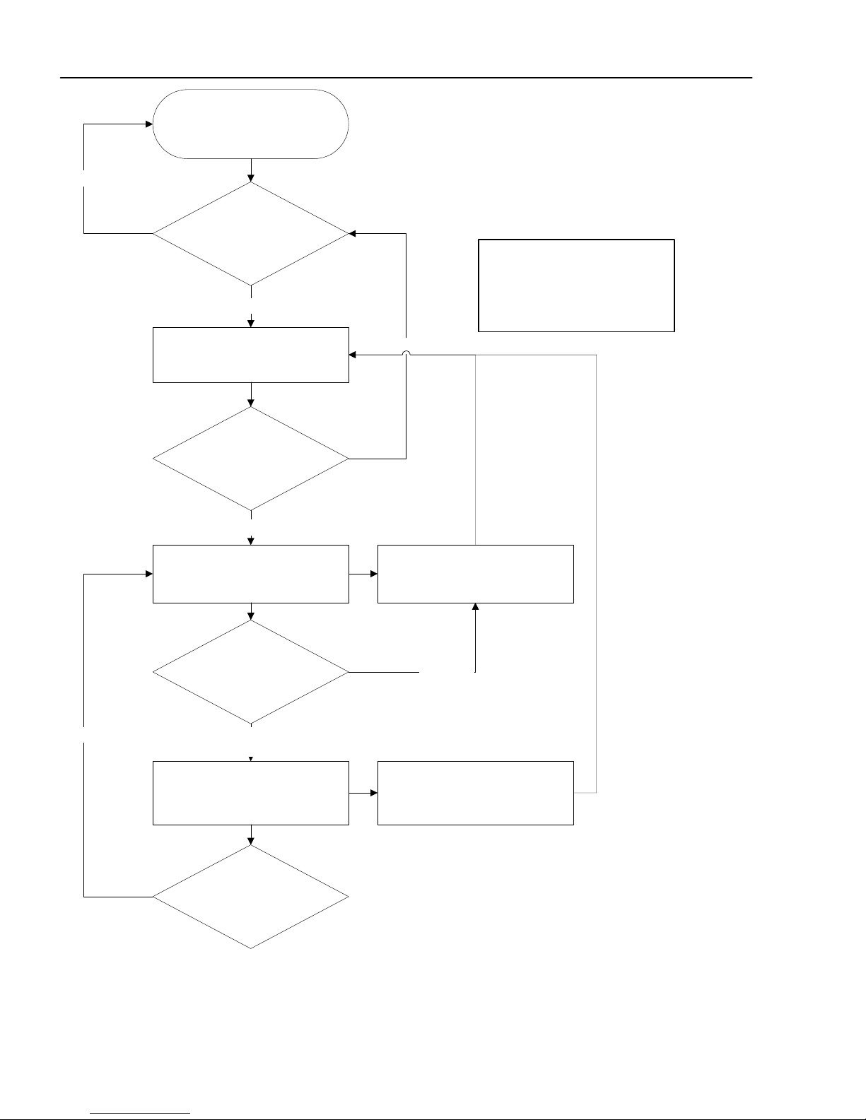
Yes
Network Customer Support Plan
Customer
Midas Network is functioning
properly?
No
Level One Contact is notified
Authorized Factory Service
Center
Resolved by Hardware repair
or Network Operations
troubleshooting?
No
Level Two Contact is notified
CEFD Customer Support
*Note: If equipment was purchased
directly from Comtech EFData (not
through a Factory Authorized
Service Center), then CEFD
Customer Support will be the initial
point of contact.
Yes
CEFD Customer Support
provides HW support
Hardware
Rack Installation, Operator’s Guide, Rev. 1
Preface
Hardware or Network
Operations issue?
Network
Operations
Level Three Contact is notified
CEFD Network Test and Field
Support
Hardware or Network
Operations issue?
iii
Hardware
CEFD Network Test and Field
Support
provides Network Operations
support
Page 6

See the Comtech EF Data website at http://www.comtechefdata.com for contact information for a Factory
Authorized Service Center. Contact the Factory Authorized Service Center for:
• Product support
• Information on upgrading or returning a product
Contact the Comtech EF Data Customer Support Department for:
• Product support or training
• Information on upgrading or returning a product
A Customer Support representative may be reached at:
Comtech EF Data
Attention: Customer Support Department
2114 West 7th Street
Tempe, Arizona 85281 USA
480.333.2200 (Main Comtech EF Data Number)
480.333.4357 (Customer Support Desk)
480.333.2500 FAX
or, E-Mail can be sent to the Customer Support Department at:
service@comtechefdata.com
To return a Comtech EF Data product (in-warranty and out-of-warranty) for repair or replacement:
1. Request a Return Material Authorization (RMA) number from the Comtech EF Data
Customer Support Department.
2. Be prepared to supply the Customer Support representative with the model number,
serial number, and a description of the problem.
3. To ensure that the product is not damaged during shipping, pack the product in its
original shipping carton/packaging.
4. Ship the product back to Comtech EF Data. (Shipping charges should be prepaid.)
Rack Installation, Operator’s Guide, Rev. 1
Preface iv
Page 7

Contact the Comtech EF Data Network Test and Field Support
• System level Network Operations support
• Information on upgrading Network Operation software
• Reporting comments or suggestions concerning manuals
A Network Test and Field Support representative may be reached at:
Comtech EF Data
Attention: Network Test and Field Support
2114 West 7th Street
Tempe, Arizona 85281 USA
480.225.2200 (Main Comtech EF Data Number)
480.225.3693 (Network Test and Field Support)
480.333.2161 FAX
or, E-Mail can be sent to the Network Test and Field Support Department at:
mailto:midasfss@comtechefdata.com
Contact us via the web at www.comtechefdata.com
.
Rack Installation, Operator’s Guide, Rev. 1
Preface
v
Page 8

This page is intentionally left blank.
Rack Installation, Operator’s Guide, Rev. 1
Preface vi
Page 9

Table of Contents
1. INTRODUCTION............................................................................................................... 1–1
Introduction................................................................................................................................................1–1
Title Box ......................................................................................................................................................1–1
Revision History..........................................................................................................................................1–1
Equipment...................................................................................................................................................1–2
Equipment Rack Elevation ..................................................................................................................1–2
Equipment View..................................................................................................................................1–2
Equipment Rack Wiring Diagram .......................................................................................................1–2
2. Equipment View................................................................................................................... 2–1
Equipment View.........................................................................................................................................2–1
CiM-300L............................................................................................................................................2–3
CiM-550...............................................................................................................................................2–4
CDM-550.............................................................................................................................................2–5
CDM-600.............................................................................................................................................2–6
SDM-300A ..........................................................................................................................................2–7
SDM-2020 Modulator .........................................................................................................................2–8
SDM-2020 Demodulator.....................................................................................................................2–9
SNM-1000.........................................................................................................................................2–10
SNM-1001.........................................................................................................................................2–11
SNM-1002.........................................................................................................................................2–12
SNM-1010.........................................................................................................................................2–13
SMS-301............................................................................................................................................2–14
3. Typical Rack Installation.................................................................................................... 3–1
General........................................................................................................................................................3–1
Required Equipment..................................................................................................................................3–2
Typical Rack Installation...........................................................................................................................3–3
Workstation .........................................................................................................................................3–3
Rack Installation..................................................................................................................................3–4
Wiring Connections.............................................................................................................................3–6
Equipment Rack History...................................................................................................................... 3-7
Rack Installation, Operator’s Guide, Rev. 1
Preface
vii
Page 10

This page is intentionally left blank.
Rack Installation, Operator’s Guide, Rev. 1
Preface viii
Page 11

About this Manual
This manual provides installation and operation information for Comtech EF Data
equipment. This is a technical information guide document intended to provide
technicians and operators responsible for the operation and maintenance of the equipment
as used in satellite communications equipment with rack installation instructions.
Overview of Changes to Previous Editions
Chapter 2 – Added views for CDM-550, CDM-600, CiM-550, and CiM-300L modems.
Chapter 3 – Added rack instructions.
Conventions and References
Metric Conversion
Comtech EF Data provides metric conversion information located on the inside back
cover of this manual. This information is provided to assist the operator in crossreferencing English to Metric conversions, as necessary.
Trademarks
Product names mentioned in this manual may be trademarks or registered trademarks of
their respective companies and are hereby acknowledged.
Reporting Comments or Suggestions
Concerning this Manual
Comments and suggestions regarding the content and design of this manual will be
appreciated. To submit comments, please contact the Comtech EF Data Technical
Publications department: techpub@comtechefdata.com
Rack Installation, Operator’s Guide, Rev. 1
Preface
ix
Page 12

Disclaimer
Comtech EF Data has reviewed this manual thoroughly in order that it will be an easy-touse guide to your product. All statements, technical information, and recommendations in
this manual and in any guides or related documents are believed reliable, but the accuracy
and completeness thereof are not guaranteed or warranted, and they are not intended to
be, nor should they be understood to be, representations or warranties concerning the
products described.
Further, Comtech EF Data reserves the right to make changes in the specifications of the
products described in this manual at any time without notice and without obligation to
notify any person of such changes.
Rack Installation, Operator’s Guide, Rev. 1
Preface x
Page 13

1
.
I
N
T
R
O
D
U
C
T
I
O
N
1
.
I
N
T
R
O
D
U
C
T
I
1
.
I
N
T
R
O
D
U
C
T
Introduction 1-1
Title Box 1-1
Revision History 1-1
Equipment 1-2
I
O
O
N
N
IInnttrroodduuccttiioonn
The objective of this document is to record the rack location and cable connection of the
Comtech EF Data provided equipment.
SSccooppee
TTiittllee BBooxx
A representation of the equipment installed into the rack, equipment front and
rear panel views, and wiring diagrams also are included.
• If a station has multiple equipment racks, then multiple documents will
be required to record each equipment rack installation (one document
per rack).
For the purpose of this manual, the equipment rack is identified as
‘Equipment Rack Number 1.’
For installation with multiple equipment racks, the rack identification number
shall be incremented.
The Title Box shall be modified to identify the required information, as shown
on the Cover.
RReevviissiioonn HHiissttoorryy
A typical ‘Revision History’ form, shall be maintained by the user to record the
following information:
• Revision Number
• Revision Date
• Revision Description
• Documentation Administrator
Rack Installation, Operator’s Guide, Rev.1
Introduction 1-1
Page 14

Revision History Form
Revision No. Revision Data Revision Description Documentation
Administrator
0 August 31, 2001 Initial Issue
1 March 25, 2002 Added modems and
rack instruction
procedures.
Rack Installation, Operator’s Guide, Rev.1
Introduction 1-2
Page 15

EEqquuiippmmeenntt
EEqquuiippmmeenntt RRaacckk
EElleevvaattiioonn
Figure 1-1 illustrates a rack with 44 rack unit locations. This rack table should
be reflecting the actual rack units installed in the equipment rack. The RU
locations start at the bottom of the rack. The unavailable RU location(s) can be
ignored.
Note: All modems are 1RU.
A description of the equipment, such as, the Controller, SNM-1000, or the
SDM-300A can be indicated in a cell of the table. A ‘Comment’ column may
be used to specify:
EEqquuiippmmeenntt VViieeww
• Node Address
• Data I/O Interface Type
• Data Circuitry functions
Views of the front and rear panels of Comtech EF Data provided equipments
are included in Chapter 2 for reference purposes. The rear panel views show
the connections required in the Wiring Diagram.
EEqquuiippmmeenntt RRaacckk
WWiirriinngg DDiiaaggrraamm
The Wiring Diagram in Figure 1-2 can be used to record the specifics of
interconnections between the units in the rack.
Rack Installation, Operator’s Guide, Rev.1
Introduction 1-3
Page 16

Rack Location
Equipment Rack Number 1
Elevation
Comments
RU 44
RU 43
RU 42
RU 41
RU 40
RU 39
RU 38
RU 37
RU 36
RU 35
RU 34
RU 33
RU 32
RU 31
RU 30
RU 29
RU 28
RU 27
RU 26
RU 25
RU 24
RU 23
RU 22 SDM300A Video Conference
RU 21
RU 20
RU 19
RU 18
RU 17
RU 16
RU 15
RU 14
RU 13
RU 12
RU 11
RU 10
RU 9
RU 8
RU 7
RU 6
RU 5
RU 4
RU 3
RU 2
RU 1
Figure 1-1. Equipment Rack
Rack Installation, Operator’s Guide, Rev.1
Introduction 1-4
Page 17

Figure 1-2. Wiring Diagram
Rack Installation, Operator’s Guide, Rev.1
Introduction 1-5
Page 18

This page is intentionally left blank.
Rack Installation, Operator’s Guide, Rev.1
Introduction 1-6
Page 19

2
2
2
.
.
.
E
E
E
q
q
q
u
u
u
i
i
i
p
p
p
m
m
m
e
e
e
n
n
n
t
t
t
V
V
V
i
i
i
e
e
e
w
w
w
EEqquuiippmmeenntt VViieeww
The following, but limited to, units are included in this manual for the purpose
of showing the front and rear panels. For additional information, refer to the
modem installation and operation manual.
Identifiers for various band frequencies are not included and reference shall be
made to the individuals installation and operation manual.
SNM-1000
SNM-1001
SDM-1002
SNM-1010
SDM-1010L
CiM-300L
CiM-550
Comtech EF Data Equipment
Node Control Modem
Network Control Modem
LinkSync Modem
Data/Control Modem
Data/Control Modem
IP Enabled Satellite Modem
IP Enabled Satellite Modem
CDM-550
CDM-600
SDM-300A
SDM-2020(M)
SDM-2020(D)
SMS-301
Satellite Modem
Satellite Modem
Satellite Modem
Satellite Modulator
Satellite Demodulator
Redundancy (Protection) Switch
Rack Installation, Operator’s Guide, Rev.1
Equipment View 2-1
Page 20

This page is intentionally left blank.
Rack Installation, Operator’s Guide, Rev.1
Equipment View 2-2
Page 21

Rack Installation, Operator’s Guide, Rev.1
Equipment View 2-3
SNM-1000
Physical:
1 RU
Size: 1.75H x 19W x 15.7D inches (4.4 x 48 x 40D cm)
Weight: ≤ 9 lbs (≤ 4 kg)
Page 22

Rack Installation, Operator’s Guide, Rev.1
Equipment View 2-4
SNM-1001
Physical:
1 RU
Size: 1.75H x 19W x 20D inches (4.4 x 48 x 51 cm)
Weight: ≤ 9 lbs (≤ 4 kg)
Page 23

Rack Installation, Operator’s Guide, Rev.1
Equipment View 2-5
SNM-1002
Physical:
1 RU
Size: 1.75H x 19W x 16D inches (4.4 x 48 x 40 cm)
Weight: ≤ 11 lbs (≤ 5 kg)
Page 24

Rack Installation, Operator’s Guide, Rev.1
Equipment View 2-6
SNM-1010
Physical:
1 RU
Size: 1.75H x 19W x 16D inches (4.4 x 48 x 40 cm)
Weight: ≤ 9 lbs (≤ 4 kg)
Page 25

Rack Installation, Operator’s Guide, Rev.1
Equipment View 2-7
SNM-1010L
Physical:
1 RU
Size: 1.75H x 19W x 16D inches (4.4 x 48 x 40 cm)
Weight: ≤ 9 lbs (≤ 4 kg)
Page 26

Rack Installation, Operator’s Guide, Rev.1
Equipment View 2-8
CiM-300L
Physical:
1RU
Size: 1.75H X 19.0W X 19.0 D inches (4.4H x 48W x 48D cm)
Weight: ≤ 9 lbs (≤ 4 kg)
Page 27

Rack Installation, Operator’s Guide, Rev.1
Equipment View 2-9
CiM-550
Physical:
1RU
Size: 1.75H x 19.0W x 18.0D inches (4.4 x 48.0 x 46 cm)
Weight: ≤ 9 lbs (≤ 4 kg)
Page 28

Rack Installation, Operator’s Guide, Rev.1
Equipment View 2-10
CDM-550
Physical:
1 RU
Size: 1.75H x 19.0W x 18.0D inches (4.4 x 48.0 x 46 cm)
Weight: ≤ 9 lbs (≤4 kg)
Page 29

Rack Installation, Operator’s Guide, Rev.1
Equipment View 2-11
CDM-600
Physical:
1 RU
Size: 1.75H x 19.0W x 13.13D inches (4.4 x 48 x 33.3 cm)
Weight: ≤ 9 lbs (≤ 4 kg)
Page 30

Rack Installation, Operator’s Guide, Rev.1
Equipment View 2-12
SDM-300A
Physical:
1 RU
Size: 1.75H x 19.0W x 14.0 inches (4.4 x 48 x 36 cm)
Weight: 9 lbs (4 kg)
Page 31

Rack Installation, Operator’s Guide, Rev.1
Equipment View 2-13
SDM-2020 Modulator
PRIME
POWER
GROUND
J1 REMOTE
FUSE HOLDER
J2 FAULT
DATA INTERFACE CONNECTIONS CP1 TX-IF
Physical:
1 RU
Size: 1.75 H x 19W x 14D inches (4.4 x 48 x 36 cm)
Weight: < 15 lbs (<7 kg)
Page 32

Rack Installation, Operator’s Guide, Rev.1
Equipment View 2-14
SDM-2020 Demodulator
Physical:
1 RU
Size: 1.75H x 48W x 14D inches (4.4 x 48 x 36 cm) Older chassis
1.75H x 48W x 16D inches (4.4 x 48 x 41 cm) New chassis
Weight: ≤ 15 lbs (≤ 7 kg)
Page 33

Rack Installation, Operator’s Guide, Rev.1
Equipment View 2-15
SMS-301
J1 REMOTE SWI T CH CONTROL
STATUS/FAULTS
REMOTE
CONTROL
J14
AC1
J11
AC2
J12
MODEM
COM
J10 J13
J9
A
MOD
J8
RX IFJ7B
J4
TX IF
J5
A
J6
B
!
100 TO 240V
1.5 A 50 TO 60 Hz
T2A, 250V
DEMOD
Physical:
1 RU
Size: 1.75H x 19W x 15D inches (4.4 x 48 x 39 cm)
Weight: < 9 lbs (<4 kg)
Page 34

Rack Installation, Operator’s Guide, Rev.1
Equipment View 2-16
This page is intentionally left blank.
Page 35

3
3
3
.
.
.
T
T
T
y
y
y
p
p
p
i
i
i
c
c
c
a
a
a
l
l
l
R
R
R
a
a
a
c
c
c
k
k
k
I
I
I
n
n
n
s
s
s
t
t
t
a
a
a
l
l
l
l
l
l
a
a
a
t
t
t
i
i
i
o
o
o
n
n
n
GGeenneerraall
RReeqquuiirreedd
EEqquuiippmmeenntt
Equipment Part No. Manufacture or Description
Adapter :
User Port
EFBUS to CDM/CiM
This section provides information to assemble a typical MIDAS System rack.
Each rack shall use an addition manual to record all the vital information
relating to that rack installation.
Additional information can be obtained via the Comtech EF Data Network
Customer Support department.
The following equipment shall be available for the rack installation. This
equipment may be obtained from Comtech EF Data, Sales and Marketing
department.
CN/AD-UP-EFA
CA/WR9440
Comtech EF Data User Port Adapter
Comtech EF Data EFBUS1 Adapter
(Used on CDM and CiM Modems)
Cables:
EFBUS1/2 Ribbon with Termination
EFBUS1/2 Ribbon without Termination
EFBUS1/2 Y-Cable
Combiner Various
Security Key (Dongle) PL/9506 Comtech EF Data
PL/0755
PL/4167
CA/CA-ESA-EF
. ICS-50-X
. ICS-75-X
Comtech EF Data
Comtech EF Data
Comtech EF Data
Comtech EF Data
Contact CEFD Sates department for
correct (-x) dash number for
customer’s requirement.
Rack Installation, Operator’s Guide, Rev.1
Typical Rack Installation 3-1
Page 36

TTyyppiiccaall RRaacckk
IInnssttaallllaattiioonn
The MIDAS System will not accept the Comtech EF Data SDM-300A
IMPORTANT
with Mux, Flex Mux, or the 100-pin J8 I/O connector installed.
WWoorrkkssttaattiioonn
The user shall construct a workstation to their specification, using the
equipment recommended by Comtech EF Data. Figure 3-1 illustrates a basic
workstation.
Note: Refer to MIDAS Software Installation Guide.
Connect supplied Y-Cable as follows:
1. Connect the supplied-cable base connector to the FASTCOM card.
2. Connect supplied-cable Port 1 connector to the Comtech EF Data supplied
EIA-422 cable from SNM-1001 Modem.
3. Cable Port 2 connector is not connected.
4. Connect 9-pin EIA-232 cable from Controller Server COM 1 port to SNM-1001
M&C port.
5. Connect 9-pin EIA-232 cable from Controller Server COM 2 port to SNM-1002
M&C port.
6. Connect 25-pin pre-programmed dongle to Controller Server 25-pin I/O port.
Rack Installation, Operator’s Guide, Rev.1
Typical Rack Installation 3-2
Page 37

Local Client
Workstation
Security Key
(Dongle)
Controller
Combiner
NMS
HPOV
FASTCOM Y-Cable
Interface RS422
RS232
Low Latency
High Speed
Connection
Combiner
NMS
Remote
HPOV
Client
Figure 3-1. FASTCOM Y-Cable Connection (Reference Only)
Rack Installation, Operator’s Guide, Rev.1
Typical Rack Installation 3-3
Page 38

RRaacckk IInnssttaallllaattiioonn
Located in Chapter 1 is the Equipment Rack form, each rack will have a form
completed to maintain continuity of the installation. Use this form to build the
rack, as follows.
Figure 3-2. Typical Rack Installation (30-Channel)
Rack Installation, Operator’s Guide, Rev.1
Typical Rack Installation 3-4
Page 39

Rack Location
Equipment Rack Number 1
Elevation
Comments
RU 44
RU 43 SNM-1001
RU 42 SNM-1002
RU 41 SDM-300A Channel # 1
RU 40 SDM-300A Channel # 2
RU 39 SDM-300A Channel # 3
RU 38 SDM-300A Channel # 4
RU 37 CDM-550T Channel # 5 [Data only]
RU 36 SDM-300A Channel # 6
RU 35 SDM-300A Channel # 7
RU 34 SDM-300A Channel # 8
RU 33 CDM-550T Channel # 9 [Reserved]
RU 32 SDM-300A Channel # 10
RU 31 SDM-300A Channel # 11
RU 30 SDM-2020 MOD Channel # 12 (TX only)
RU 29 SDM-2020 MOD Channel # 13 (TX Only)
RU 28 SDM-2020 DEMOD Channel # 14 (RX Only)
RU 27 SDM-2020 DEMOD Channel # 15 (RX Only)
RU 26 SDM-300A Channel # 16
RU 25 SDM-300A Channel # 17
RU 24 SDM-300A Channel # 18
RU 23 SDM-300A Channel # 19
RU 22 SDM-300A Channel 20 [Video Conference]
RU 21 CDM-550 Channel 21
RU 20 CDM-550 Channel 22
RU 19 CDM-550 Channel 23
RU 18 CDM-550 Channel 24
RU 17
RU 16
RU 15 CiM-550 Channel 25
RU 14 CDM-550 Channel 26
RU 13 SDM-8000 Channel 27
RU 12 SDM-6000 Channel 28
RU 11
RU 10
RU 9
RU 8
RU 7
RU 6
RU 5
RU 4
RU 3
RU 2
RU 1
SNM-1000
Combiner
Combiner
Controller
TX Only
RX Only
Figure 3-3. Sample Completed Equipment Rack Form
Rack Installation, Operator’s Guide, Rev.1
Typical Rack Installation 3-5
Page 40

WWiirriinngg
CCoonnnneeccttiioonn
Located in Chapter 1 is the Wiring Diagram form, each rack will have a form
completed to maintain continuity of the installation. Record all wiring
connections and secure form with the equipment rack.
Observe the addition information needed to complete the wiring connections,
as follows:
1. Connect Adapter P/N CA/WR9440 as appropriate :
a. Connect Adapter P/N CA/WR9440 to all Comtech EF Data CDM modems
installed in the equipment rack, at the REMOTE CONTROL port.
b. Connect Adapter P/N CA/WR9440 to all Comtech EF Data CiM modems
installed in the equipment rack, at the IP REMOTE port.
2. Connect EFBUS 1/2 Y-Cable Part No. CA/CA-ESA-EF to SNM-1000 EFBUS 1/2
3. Connect BNC Cables to TX-IF (CP1) BNC connectors to all units. Connect to the
4. Connect BNC Cables to RX-IF (CP2) BNC connectors to all units. Connect to the
5. Connect Data connectors (J8) of all units in the equipment rack, in series to a
6. Connect combiner to the KST-2000L Satellite Terminal equipment.
connector J6. Connect a ribbon-cable serial cable to all EFBUS 1/2 connectors (J6).
Combiner.
combiner.
combiner.
Rack Installation, Operator’s Guide, Rev.1
Typical Rack Installation 3-6
Page 41

EEqquuiippmmeenntt RRaacckk
HHiissttoorryy
Located on the cover of this manual is the Title Box, fill in the required
information for each equipment rack, as shown in the following sample:
Title Box:
• Station Type: ABCDE_______________________
• Station Location: Phoenix, Arizona_______________________
• Equipment Rack’s Configuration Revision: AA_____
• Data of Last Revision: July 4, 2001_________________
• Project Title: Nelson__________________________
• End User: FGHIJK_____________________
Rack Installation, Operator’s Guide, Rev.1
Typical Rack Installation 3-7
Page 42

This page is intentionally left blank.
Rack Installation, Operator’s Guide, Rev.1
Typical Rack Installation 3-8
Page 43

METRIC CONVERSIONS
Units of Length
Unit
1 centimeter — 0.3937 0.03281 0.01094
1 inch 2.540 — 0.08333 0.2778
1 foot 30.480 12.0 — 0.3333
1 yard 91.44 36.0 3.0 —
Centimeter
Inch
Foot
Yard
Mile
6.214 x 10
1.578 x 10
1.893 x 10
5.679 x 10
Meter
-6
0.01 — —
-5
0.254 — 25.4
-4
0.3048 — —
-4
0.9144 — —
Kilometer Millimeter
1 meter 100.0 39.37 3.281 1.094
1 mile
1 mm — 0.03937 — — — — — —
1 kilometer — — — — 0.621 — — —
1.609 x 10
5
6.336 x 10⁴ 5.280 x 10³ 1.760 x 10³
6.214 x 10
-4
—
— — —
1.609 x 10³
1.609 —
Temperature Conversions
Unit
32° Fahrenheit
212° Fahrenheit
-459.6° Fahrenheit
° Fahrenheit
—
—
—
° Centigrade
0
(water freezes)
100
(water boils)
273.1
(absolute 0)
Formulas
C = (F - 32) * 0.555
F = (C * 1.8) + 32
Units of Weight
Unit
1 gram — 0.03527 0.03215 0.002205 0.002679 0.001
Gram
Ounce
Avoirdupois
Ounce
Troy
Pound
Avoir.
Pound
Troy
Kilogram
1 oz. avoir. 28.35 — 0.9115 0.0625 0.07595 0.02835
1 oz. troy 31.10 1.097 — 0.06857 0.08333 0.03110
1 lb. avoir. 453.6 16.0 14.58 — 1.215 0.4536
1 lb. Troy 373.2 13.17 12.0 0.8229 — 0.3732
1 kilogram
1.0 x 10
3
35.27 32.15 2.205 2.679 —
Page 44

2114 WEST 7TH STREET TEMPE ARIZONA 85281 USA
480 • 333 • 2200 PHONE
480 • 333 • 2161
FAX
 Loading...