

Page 1

Comtech EF Data is a n
AS9100 Rev B / ISO9001:2000 Registered Company
Vipersat
CDD-56X Series
Satellite Network Demodulator Router
User Guide
CDD-562L
CDD-564/564L
MN/22137 Revision 1
Page 2

Page 3
Vipersat CDD-56X Series
CDD-562L, CDD-564/564L
Satellite Network Demodulator Router
User Guide
Part number MN/22137
Document Revision 1
Firmware Version 1.6.11/2.6.11
April 21, 2013
Page 4

COMTECH EF DATA
VIPERSAT Network Products Group
3215 Skyway Court
Fremont, CA 94539
USA
Phone: (510) 252-1462
Fax: (510) 252-1695
www.comtechefdata.com
Part Number: MN/22137
Revision: 1
Firmware Version: 1.6.11/2.6.11
©2013 by Comtech EF Data, Inc. All rights reserved. No part of this manual may be copied or
reproduced without prior written permission of Comtech EF Data, Inc.
IMPORTANT NOTE: The information contained in this document supersedes all previously
published information regarding this product. Product specifications are subject to change
without prior notice.
Comtech reserves the right to revise this publication at any time without obligation to provide
notification of such revision. Comtech periodically revises and improves its products and,
therefore, the information in this document is subject to change without prior notice. Comtech
makes no warranty of any kind with regard to this material, including but not limited to the implied
warranties of merchantability and fitness for a particular purpose. No responsibility for any errors
or omissions that may pertain to the material herein is assumed. Comtech makes no
commitment to update nor to keep current the information contained in this document.
Patents and Trademarks
All products, names and services are trademarks or registered trademarks of their respective
companies. See all of Comtech EF Data’s patents and patents pending at
http://patents.comtechefdata.com.
Printed in the United States of America
Page 5

Document Revision History
Revision Date Description
0 3/10/08 Initial Release
Note: This new document part number, MN/22137, supersedes the
previous CDD-56X User Guide part number, 22137.
New functionality in v1.5.4: New DPC enhancements; STDMA
Power Hunt; Hitless Switching; New VMS registration and Managing
Address method; UDP Port Base Address selection; Auto Home
State Failsafe; SOTM.
1 4/21/13 Update content to reflect NP v1.6.11/2.6.11.
New Features: Dynamic Entry Channel Mode (ECMv2).
Page 6

{ This Page is Intentionally Blank }
Page 7

Table of Contents
Chapter 1
General
How to Use This Manual . . . . . . . . . . . 1-1
Manual Organization . . . . . . . . . . . . 1-1
Chapter 1 — General . . . . . . . . . 1-1
Chapter 2 — Quick Start Configuration 1-1
Chapter 3 — Using the Command Line
Interface (CLI) . . . . . . . . . . . . 1-2
Appendix A — Network Addressing . . 1-2
Appendix B — Automatic Switching . . 1-2
Appendix C — Dynamic Power Control1-2
Appendix D — ECM Migration . . . . . 1-2
Appendix E — Glossary . . . . . . . . 1-2
Conventions and References . . . . . . . . 1-2
Product Description . . . . . . . . . . . . . . 1-4
Introduction . . . . . . . . . . . . . . . 1-4
Demodulator Features . . . . . . . . . . 1-4
Router Features . . . . . . . . . . . . . 1-4
Network and Bandwidth Management . . 1-5
Dynamic SCPC (dSCPC) . . . . . . . . 1-5
STDMA . . . . . . . . . . . . . . . . . 1-6
Single Hop On Demand . . . . . . . . . 1-6
Turbo Product Coding . . . . . . . . . . 1-6
Header Decompression . . . . . . . . . 1-6
Payload Decompression. . . . . . . . . 1-7
Data Decryption . . . . . . . . . . . . . 1-7
New in This Release. . . . . . . . . . . . . 1-7
1.6.11/2.6.11 Release . . . . . . . . . . 1-7
Dynamic Entry Channel Mode . . . . . 1-7
Customer Support . . . . . . . . . . . . . . . 1-8
Contact Information . . . . . . . . . . . 1-8
Return Material Authorization . . . . . . 1-8
Reader Comments / Corrections . . . . 1-8
Chapter 2
Quick Start Configuration
Introduction . . . . . . . . . . . . . . . . . . 2-1
Initial Configuration . . . . . . . . . . . . . . 2-2
Terminal Connection . . . . . . . . . . . 2-2
Network Role . . . . . . . . . . . . . . . . 2-2
Setting Vipersat CDD-56X Operating
Parameters . . . . . . . . . . . . . . . . . 2-3
Set the Feature Configuration . . . . . . 2-3
Set the IP Address . . . . . . . . . . . 2-6
Configure the Route Table . . . . . . . 2-7
Routing in a Vipersat Network. . . . . 2-7
Creating the Routes . . . . . . . . . . 2-8
Set the Satellite Demod Configuration . 2-9
Set the Vipersat Configuration . . . . 2-10
Chapter 3
Using the Command Line Interface
(CLI)
General . . . . . . . . . . . . . . . . . . . . . 3-1
Common Screen Commands . . . . . . . . 3-2
Demod Select . . . . . . . . . . . . . . 3-2
Save Parameters to Permanent Storage 3-2
Exit . . . . . . . . . . . . . . . . . . . 3-2
Telnet Logout . . . . . . . . . . . . . . 3-2
Menu Descriptions . . . . . . . . . . . . . . . 3-3
Main Menu . . . . . . . . . . . . . . . . . 3-3
Administration . . . . . . . . . . . . . . 3-3
Feature Configuration . . . . . . . . . . . . 3-5
Vipersat Feature Codes . . . . . . . . . 3-5
Vipersat Management . . . . . . . . . . 3-6
Vipersat STDMA . . . . . . . . . . . . 3-6
Vipersat Auto Switching . . . . . . . . . 3-6
Vipersat File Streamer. . . . . . . . . . 3-7
Vipersat Configuration . . . . . . . . . . . . . 3-8
STDMA Mode . . . . . . . . . . . . . . . . 3-8
STDMA . . . . . . . . . . . . . . . . . 3-9
STDMA Tx Rate. . . . . . . . . . . . 3-10
Hub Type . . . . . . . . . . . . . . . 3-10
1 – Fixed . . . . . . . . . . . . . . 3-11
2 – Dynamic Slot . . . . . . . . . . 3-11
3 – Dynamic Cycle . . . . . . . . . 3-11
4 – GIR . . . . . . . . . . . . . . . 3-11
5 – Entry Channel . . . . . . . . . . 3-12
6 – ECMv2 . . . . . . . . . . . . . 3-12
ECMv2 Mode . . . . . . . . . . . . . 3-13
Group ID. . . . . . . . . . . . . . . . 3-14
STDMA Max Power Hunt . . . . . . . 3-14
Low Data Rate Fast Acquisition . . . . 3-15
Burstmap Multicast IP . . . . . . . . . 3-15
Outbound IP. . . . . . . . . . . . . . 3-16
Cycles Per Burst Map . . . . . . . . . 3-16
Table of Contents i
Page 8

MN/22137, rev 1
Slot Guardband . . . . . . . . . . . . 3-17
Slot Preamble Length . . . . . . . . . 3-18
Slot Data Length. . . . . . . . . . . . 3-18
Nominal Data Length . . . . . . . . . 3-19
Maximum Data Length. . . . . . . . . 3-19
Minimum Data Length . . . . . . . . . 3-20
Total Slot Count . . . . . . . . . . . . 3-20
Slot Cycle Length . . . . . . . . . . . 3-21
Slot Start in Cycle . . . . . . . . . . . 3-21
Set Remotes. . . . . . . . . . . . . . 3-21
Adding a Remote to the STDMA Group .
3-22
Base . . . . . . . . . . . . . . . . . 3-23
Remote Count . . . . . . . . . . . . 3-23
Set Remote Policies . . . . . . . . . 3-24
Delete Remote. . . . . . . . . . . . 3-26
Enable/Disable Remote . . . . . . . 3-27
View Remote(s) . . . . . . . . . . . 3-27
Remove Timeout . . . . . . . . . . 3-28
Remove Retry Timeout . . . . . . . 3-28
LNB LO Frequency . . . . . . . . . . 3-29
Satellite Frequency Conversion . . . . 3-29
STDMA Statistics . . . . . . . . . . . 3-30
Stats Accumulation Window . . . . . 3-30
Clear . . . . . . . . . . . . . . . . . 3-31
Show Hub Statistics . . . . . . . . . . 3-31
STDMA/SCPC Automatic Switching. . . . 3-32
Auto Switching . . . . . . . . . . . . . 3-33
Current WAN Transmit Mode . . . . . 3-34
Load Switching . . . . . . . . . . . . 3-34
STDMA Slot Capacity . . . . . . . . . 3-34
STDMA Switch Delay . . . . . . . . . 3-35
Percent Allocation . . . . . . . . . . . 3-35
Keep Alive Timer for Carrier Inhibit . . 3-36
Hitless Switching Parameters . . . . . 3-36
Delay for Mod . . . . . . . . . . . . 3-37
Delay for Demod. . . . . . . . . . . 3-37
LockTimes . . . . . . . . . . . . . . 3-37
Apply Delay Values . . . . . . . . . 3-38
SOTM Update . . . . . . . . . . . . . 3-38
Unit Role. . . . . . . . . . . . . . . . . . 3-38
Expansion Unit . . . . . . . . . . . . . . 3-39
Network ID. . . . . . . . . . . . . . . . . 3-39
Unit Name . . . . . . . . . . . . . . . . . 3-40
Receive Multicast Address . . . . . . . . 3-40
Managing IP Address . . . . . . . . . . . 3-41
Management Security . . . . . . . . . . . 3-42
Primary Heart Beat . . . . . . . . . . . . 3-44
Home State Revert . . . . . . . . . . . . 3-44
Dynamic Power Control Configuration . . 3-44
DPC Enabled . . . . . . . . . . . . . 3-46
Speed Up EbNo . . . . . . . . . . . . 3-46
Target DPC Address . . . . . . . . . 3-46
Set Home State Parameters . . . . . . . 3-47
Set Current Configuration as Home State. .
3-48
Force Modem to Home State . . . . . 3-48
STDMA State . . . . . . . . . . . . . 3-49
Receive Frequency . . . . . . . . . . 3-49
Receive Data Rate . . . . . . . . . . 3-49
Receive FEC Type . . . . . . . . . . 3-50
Receive Coding Rate . . . . . . . . . 3-50
Receive Modulation Type . . . . . . . 3-51
Vipersat Summary . . . . . . . . . . . . 3-51
Vipersat Migration. . . . . . . . . . . . . 3-52
UDP Port Base Address . . . . . . . . . 3-53
Alerts . . . . . . . . . . . . . . . . . . . 3-53
Appendix A
Network Addressing
Introduction . . . . . . . . . . . . . . . . . . A-1
The OSI Reference Model . . . . . . . . . . A-2
Layers 1 – 3 . . . . . . . . . . . . . . . . . A-2
Binary Math . . . . . . . . . . . . . . . . . . A-4
IP Addressing . . . . . . . . . . . . . . . . . A-6
IP Address Classes . . . . . . . . . . . . . A-6
Class A . . . . . . . . . . . . . . . . A-6
Class B . . . . . . . . . . . . . . . . A-6
Class C . . . . . . . . . . . . . . . . A-7
Class D . . . . . . . . . . . . . . . . A-7
Class E . . . . . . . . . . . . . . . . A-8
Private Network IP Addresses . . . . . A-8
Network Address Translation (NAT). . . A-8
Subnets . . . . . . . . . . . . . . . . . . . A-8
Subnet Mask . . . . . . . . . . . . . . . . A-9
Network Segments . . . . . . . . . . . . A-10
Default Gateways . . . . . . . . . . . . . A-11
MAC Addresses. . . . . . . . . . . . . . A-11
Appendix B
Automatic Switching
General . . . . . . . . . . . . . . . . . . . . B-1
Hitless Switching . . . . . . . . . . . . . . B-2
Load Switching . . . . . . . . . . . . . . . . B-4
Overview . . . . . . . . . . . . . . . . . . B-4
ii Vipersat CDD-56X Series User Guide
Page 9

MN/22137, rev 1
Bandwidth Allocation and Load Switching by
the Hub STDMA Burst Controller . . . B-5
Load Switching—STDMA Hub . . . . . . .B-8
Hub Switching Parameters . . . . . . .B-8
Hub Switching Process . . . . . . . . .B-9
Load Switching—Remote . . . . . . . . . B-10
Remote Switching Parameters . . . . B-10
Determination for Switching . . . . . . B-12
Load Switch Example . . . . . . . . . . . B-13
Reduced Data Flow in Switched Mode
(SCPC) . . . . . . . . . . . . . . . B-14
Application Switching . . . . . . . . . . . . . B-16
ToS Switching . . . . . . . . . . . . . . . . . B-18
ToS Background . . . . . . . . . . . . . . B-18
Detection of ToS Stamped Packets . . B-19
Configuration . . . . . . . . . . . . . B-20
Example Implementations . . . . . . . . . B-21
ToS Switching Per Device . . . . . . . B-21
ToS Switching Per Traffic Type . . . . B-21
ToS Remarking . . . . . . . . . . . . B-22
ToS to DSCP Value Conversions . . . B-23
Mesh Setup Based on ToS Detection . B-24
Entry Channel Mode Switching . . . . . . . . B-25
STDMA Entry Channel Mode . . . . . . . B-25
Fail-Safe Operation . . . . . . . . . . B-26
Using STDMA ECM . . . . . . . . . . B-28
Switching an ECM Remote from SCPC to
STDMA. . . . . . . . . . . . . . . B-29
Dynamic Entry Channel Mode. . . . . . . B-31
Hub Configuration . . . . . . . . . . . B-32
Remote Configuration . . . . . . . . . B-33
ECM Processing. . . . . . . . . . . . B-34
Calibrated Data Rate . . . . . . . . C-13
DPC Margin . . . . . . . . . . . . . C-13
Nominal Power Level . . . . . . . . C-13
Max Data Rate . . . . . . . . . . . C-13
Max Code Rate . . . . . . . . . . . C-13
Max Modulation . . . . . . . . . . . C-13
Max FEC Type . . . . . . . . . . . C-13
Calculate Max Power . . . . . . . . C-13
Max Power . . . . . . . . . . . . . C-14
Signal Power Level Considerations . . . . . . C-15
Power Considerations. . . . . . . . . . . C-16
Cabling Considerations . . . . . . . . . . C-16
Appendix D
ECM Migration
General . . . . . . . . . . . . . . . . . . . . D-1
Migration Procedure . . . . . . . . . . . . . D-3
Configure Remote Units. . . . . . . . . . . D-3
Configure Hub Unit . . . . . . . . . . . . . D-5
Appendix E
Glossary
. . . . . . . . . . . . . . . . . . . . . . . . . E-1
Appendix C
Dynamic Power Control
Introduction . . . . . . . . . . . . . . . . . . C-1
Description . . . . . . . . . . . . . . . . . . C-3
BER Waterfall Mapping . . . . . . . . .C-3
Delta Power Compensation . . . . . . .C-3
Theory of Operation . . . . . . . . . . . . .C-4
Configuration . . . . . . . . . . . . . . . . . C-7
Main DPC Menu . . . . . . . . . . . . . . .C-9
Enable DPC . . . . . . . . . . . . . C-10
Target Eb/No . . . . . . . . . . . . C-10
Speed Up Eb/No Range . . . . . . . C-11
Target DPC (IP) Address . . . . . . C-11
Calculate Max Power Menu . . . . . . . . C-11
Table of Contents iii
Page 10

{ This Page is Intentionally Blank }
MN/22137, rev 1
iv Vipersat CDD-56X Series User Guide
Page 11

List of Figures
Chapter 2 Figures
Figure 2-1 Main Menu screen. . . . . . . . . . . . . . 2-4
Figure 2-2 Administration screen . . . . . . . . . . . 2-4
Figure 2-3 Feature Configuration screen . . . . . 2-5
Figure 2-4 FAST Feature Code dialog . . . . . . . 2-5
Figure 2-5 Working Mode dialog . . . . . . . . . . . 2-6
Figure 2-6 Ethernet Interface screen . . . . . . . . 2-7
Figure 2-7 Configuring the Route Table screen 2-9
Figure 2-8 Rx Configuration screen . . . . . . . . 2-10
Figure 2-9 Vipersat Configuration screen (Hub). .
2-10
Chapter 3 Figures
Figure 3-1 Main Menu screen. . . . . . . . . . . . . . 3-3
Figure 3-2 Administration screen . . . . . . . . . . . 3-4
Figure 3-3 Working Mode dialog . . . . . . . . . . . 3-4
Figure 3-4 Feature Configuration screen . . . . . 3-5
Figure 3-5 FAST Feature Code dialog . . . . . . . 3-6
Figure 3-6 Vipersat Configuration screen (Hub)3-8
Figure 3-7 STDMA screen (Hub, STDMA, Fixed
type). . . . . . . . . . . . . . . . . . . . . . . . . . . . 3-9
Figure 3-8 STDMA screen (Hub/Remote, SCPC)
3-9
Figure 3-9 Hub Type prompt . . . . . . . . . . . . . 3-10
Figure 3-10 ECMv2 Mode prompt . . . . . . . . . 3-13
Figure 3-11 Group ID prompt . . . . . . . . . . . . . 3-14
Figure 3-12 STDMA Max Power Hunt prompt 3-15
Figure 3-13 Burstmap Multicast IP prompt . . . 3-16
Figure 3-14 Outbound IP prompt . . . . . . . . . . 3-16
Figure 3-15 Cycles per Burst Map prompt . . . 3-17
Figure 3-16 Slot Guardband prompt. . . . . . . . 3-17
Figure 3-17 Slot Preamble Length prompt . . . 3-18
Figure 3-18 Slot Data Length prompt . . . . . . . 3-19
Figure 3-19 Nominal Data Length prompt . . . 3-19
Figure 3-20 Maximum Data Length prompt . . 3-20
Figure 3-21 Minimum Data Length prompt. . . 3-20
Figure 3-22 Total Slot Count prompt . . . . . . . 3-21
Figure 3-23 STDMA Remotes Menu screen . 3-22
Figure 3-24 Remote Name and IP Address prompt
3-22
Figure 3-25 Base Remote Display prompt . . . 3-23
Figure 3-26 STDMA Remote Policies screen (GIR
Hub) . . . . . . . . . . . . . . . . . . . . . . . . . . . 3-24
Figure 3-27 GIR Remote Policies prompt . . . . 3-25
Figure 3-28 Entry Channel Switch Rates screen .
3-25
Figure 3-29 Remote SCPC Data Rate prompt3-26
Figure 3-30 Global SCPC Data Rate prompt .3-26
Figure 3-31 Global Switch Type prompt . . . . .3-26
Figure 3-32 Delete Remote prompt . . . . . . . .3-27
Figure 3-33 Enable/Disable Remote prompt .3-27
Figure 3-34 View Remote(s) screen . . . . . . . .3-27
Figure 3-35 Remove Timeout prompt . . . . . . . 3-28
Figure 3-36 Remove Retry Timeout prompt . .3-28
Figure 3-37 LNB LO Frequency prompt . . . . .3-29
Figure 3-38 Satellite Frequency Conversion prompt
3-29
Figure 3-39 STDMA Statistics screen (Hub). .3-30
Figure 3-40 STDMA Statistics screen (Remote). .
3-30
Figure 3-41 Stats Accumulation Window prompt .
3-31
Figure 3-42 Show Hub Statistics screen. . . . . 3-31
Figure 3-43 Automatic Switching screen . . . .3-33
Figure 3-44 STDMA Slot Capacity prompt . . .3-34
Figure 3-45 STDMA Switch Delay prompt . . . 3-35
Figure 3-46 Percent Allocation prompt . . . . . .3-35
Figure 3-47 Keep Alive Timer for Carrier Inhibit
prompt . . . . . . . . . . . . . . . . . . . . . . . . .3-36
Figure 3-48 Hitless Switching screen . . . . . . .3-37
Figure 3-49 Set LockTime prompt . . . . . . . . .3-38
Figure 3-50 Unit Role prompt . . . . . . . . . . . . .3-38
Figure 3-51 Expansion Unit prompt . . . . . . . .3-39
Figure 3-52 Network ID prompt . . . . . . . . . . .3-40
Figure 3-53 Unit Name prompt . . . . . . . . . . . .3-40
Figure 3-54 Receive Multicast IP Address prompt
3-41
Figure 3-55 Managing IP Address prompt . . . 3-41
Figure 3-56 Vipersat Management Security screen
3-43
Figure 3-57 Encryption Key Entry prompt. . . . 3-43
Figure 3-58 DPC Configuration screen (Hub,
STDMA) . . . . . . . . . . . . . . . . . . . . . . . .3-45
Figure 3-59 DPC Configuration screen (Hub/
Remote, SCPC) . . . . . . . . . . . . . . . . . .3-45
Figure 3-60 Speed Up EbNo prompt . . . . . . .3-46
Figure 3-61 Target DPC Address prompt . . . .3-47
List of Figures v
Page 12

MN/22137, rev 1
Figure 3-62 Home State Configuration screen3-48
Figure 3-63 Force Modem to Home State warning
3-49
Figure 3-64 Receive Frequency prompt . . . . . 3-49
Figure 3-65 Receive Data Rate prompt . . . . . 3-50
Figure 3-66 Receive FEC Type prompt . . . . . 3-50
Figure 3-67 Receive Coding Rate prompt . . . 3-50
Figure 3-68 Receive Modulation Type prompt3-51
Figure 3-69 Vipersat Summary screen. . . . . . 3-51
Figure 3-70 Vipersat Migration prompt . . . . . . 3-53
Figure 3-71 UDP Port Base Address prompt . 3-53
Appendix A Figures
Figure A-1 The Seven OSI Protocol Layers . . .A-2
Figure A-2 Bits and Bytes. . . . . . . . . . . . . . . . .A-4
Figure A-3 Binary to Decimal Conversion . . . .A-4
Figure A-4 IP Address Classes A, B, C . . . . . .A-7
Figure A-5 NAT Router Example . . . . . . . . . . .A-8
Figure A-6 Default Subnet Masks for IP Classes .
A-9
Figure A-7 ANDing an IP address and a subnet
mask . . . . . . . . . . . . . . . . . . . . . . . . . .A-10
Figure A-8 Network Segments . . . . . . . . . . . .A-10
Figure A-9 Router as Default Gateway. . . . . .A-11
Figure A-10 Network Node MAC Addresses .A-12
Appendix B Figures
Figure B-1 Hitless Switching screen. . . . . . . . .B-2
Figure B-2 Auto Switching Menu, CDM-570/570L
Hub . . . . . . . . . . . . . . . . . . . . . . . . . . . .B-8
Figure B-3 Hub Load Switching Page, SLM-5650A
B-8
Figure B-4 Auto Switching Menu, CDM-570/570L
Remote . . . . . . . . . . . . . . . . . . . . . . . .B-11
Figure B-5 Remote Load Switching Page, SLM-
5650A . . . . . . . . . . . . . . . . . . . . . . . . .B-11
Figure B-6 Load Switching diagram . . . . . . . .B-13
Figure B-7 Application Switching diagram . . .B-16
Figure B-8 ToS Field Location within the IP Header
B-18
Figure B-9 Remote ToS Switching menu . . . .B-20
Figure B-10 Per Device ToS Switching Example .
B-21
Figure B-11 Per Type ToS Switching Example . .
B-22
Figure B-12 ToS Remarking Application . . . B-23
Figure B-13 ToS and DSCP Conversion Chart . .
B-23
Figure B-14 ECM Switch Recovery: < 3 minutes .
B-27
Figure B-15 ECM Switch Recovery: > 3 minutes .
B-28
Figure B-16 STDMA Page with Entry Channel
Mode, CDM-570/570L . . . . . . . . . . . . B-29
Figure B-17 ECM Remote List Page, CDM-570/
570L . . . . . . . . . . . . . . . . . . . . . . . . . . B-30
Figure B-18 Remote Bandwidth Entry, CDM-570/
570L . . . . . . . . . . . . . . . . . . . . . . . . . . B-30
Figure B-19 Revert Uplink Carrier Command, VMS
modem . . . . . . . . . . . . . . . . . . . . . . . . B-31
Figure B-20 Entry Channel Mode v2 Configuration,
Hub (CDD-564L) . . . . . . . . . . . . . . . . B-33
Figure B-21 Entry Channel Mode v2 Configuration,
Remote (CDM-570L) . . . . . . . . . . . . . B-34
Figure B-22 ECMv2 Processing Diagram. . . B-35
Appendix C Figures
Figure C-1 Data Rate to Power Relationship, DPC
C-5
Figure C-2 Excessive Max Power Example . . C-6
Figure C-3 DPC Configuration screen, CLI . . C-9
Figure C-4 DPC dialog, Parameter Editor . . C-10
Figure C-5 DPC Calculate Max Power screen, CLI
C-12
Figure C-6 DPC Calibration dialog, Parameter
Editor . . . . . . . . . . . . . . . . . . . . . . . . . C-12
Figure C-7 Signal Power Levels, Remote SiteC-15
Appendix D Figures
Figure D-1 STDMA Configuration Page, Remote
CDM-570/L. . . . . . . . . . . . . . . . . . . . . . D-4
Figure D-2 STDMA Configuration Menu, Hub Type
Selection . . . . . . . . . . . . . . . . . . . . . . . D-5
Figure D-3 STDMA Menu, ECMv2 Hub Type . D-6
Figure D-4 Switch Rate Limits, InBand Return Path
Settings Page. . . . . . . . . . . . . . . . . . . . D-7
vi Vipersat CDD-56X Series User Guide
Page 13

Chapter 2 Tables
Table 2-1 CDD-56X Network Roles and Functions
2-3
Table 2-2 Vipersat Feature Configuration . . . . 2-6
Appendix B Tables
Table B-1 STDMA ACK Message . . . . . . . . . .B-6
Table B-2 ToS Switching Settings . . . . . . . . .B-20
Appendix C Tables
Table C-1 DPC Parameters, Main Menu . . . . .C-7
Table C-2 DPC Parameters, Calculate Max Power
Menu . . . . . . . . . . . . . . . . . . . . . . . . . . .C-8
Table C-3 Typical Coaxial Cable Characteristics .
C-17
List of Tables
List of Tables vii
Page 14

{ This Page is Intentionally Blank }
MN/22137, rev 1
viii Vipersat CDD-56X Series User Guide
Page 15

GENERAL
How to Use This Manual
This manual documents the enhanced Vipersat features and functions of the
CDD-56X Series (CDD-562L, CDD-564, and CDD-564L) of Satellite Network
Demodulator Routers, and guides the user in how to configure these products
for use in a Vipersat network. The material covered addresses only those areas
specific to a CDD-56X running in Vipersat mode, and complements the universal features and functions described in the CDD-564L Installation and Opera-
tion Manual.
C
HAPTER
Earth station engineers, technicians, and operators responsible for the configuration and maintenance of the CDD-56X are the intended audience for this
document.
Manual Organization
This User’s Guide is organized into the following sections:
Chapter 1 — General
Contains CDD-56X product description, customer support information, and
manual conventions and references.
Chapter 2 — Quick Start Configuration
Covers the initial basic steps that are necessary for configuring the CDD-56X
from a factory default state to a functional network element.
Chapter 1 - General 1-1
Page 16

Ho w t o Us e T h i s Ma n u a l MN/22137, rev 1
NOTE
Chapter 3 — Using the Command Line Interface (CLI)
Describes the use of the CLI for configuring and monitoring the CDD-56X in a
Vipersat network. Each CLI screen is presented along with a detailed description and related commands.
Appendix A — Network Addressing
Supplemental reference information on binary math and network addressing to
assist with integrating the CDD-56X into a Vipersat network.
Appendix B — Automatic Switching
Supplemental reference information on the Vipersat feature that provides load
switching (response to network traffic load), application switching (response to
traffic type) functions, and Entry Channel Mode switching functions.
Appendix C — Dynamic Power Control
A description of Vipersat’s DPC feature and its functionality in a network of
CDM-570/CDD-56X series equipment.
Appendix D — ECM Migration
Procedural instructions on migrating a Vipersat network of CDM-570/CDD56X series equipment from STDMA Entry Channel Mode (ECMv1) to Dynamic
Entry Channel Mode (ECMv2).
Appendix E — Glossary
A glossary of terms that pertain to Vipersat satellite network technology.
Conventions and References
The following conventions are utilized in this manual to assist the reader:
Note: Provides important information relevant to the accompanying
text.
Tip: Provides complementary information that facilitates the
associated actions or instructions.
1-2 Vipersat CDD-56X Series User Guide
Page 17

MN/22137, rev 1 Ho w t o U se T h i s M a n u a l
Caution: Explanatory text that notifies the reader of possible
Warning: Explanatory text that notifies the reader of potential harm
consequences of an action.
as the result of an action.
The following documents are referenced in this manual, and provide supplementary information for the reader:
• CDD-564L L-Band Quad Demodulator with IP Module Installation and
Operation Manual (Part Number MN/CDD564L.IOM)
• CDM-570/570L Modem Installation and Operation Manual (Part Number
MN/CDM570L.IOM)
• Vipersat CDM-570/570L User Guide (Part Number MN/22125)
• Vipersat CDM-570/L, CDD-56X Parameter Editor User Guide (Part
Number MN-0000038)
• Vipersat Management System User Guide (Part Number MN/22156)
• VLoad Utility User Guide (Part Number MN/22117)
Chapter 1 - General 1-3
Page 18

Product Description MN/22137, rev 1
Product Description
Introduction
The Vipersat CDD-56X Satellite Network Demodulator Router is ideal for
operators wishing to supply mesh connectivity between sites, while keeping
network infrastructure costs down. The CDD-564 and CDD-564L provide four
separate demodulators (the CDD-562L provides two) and an integrated router in
a compact, cost-effective 1RU package.
The CDD-56X simplifies Hub site installations by reducing rack space and cost
with 2/4 independent demodulators in a single chassis. A bank of CDD-56X
demodulators is ideal for a star network consisting of a single outbound carrier
at the Hub with multiple carriers returned from the remote sites.
The CDD-56X can be used at Hub sites where multiple burst controllers are
needed. Demodulator roles are defined via software, configurable either as a
burst controller in STDMA (Selective Time Division Multiple Access) mode, or
as dedicated SCPC (Single Channel per Carrier) inbounds from remote terminals.
At Remote sites, the CDD-56X supports mesh connectivity between multiple
sites. Operating in mesh topology with links directly between sites eliminates
double-hops through the Hub, conserving bandwidth and reducing latency.
Demodulator Features
• 50–90 MHz or 100–180 MHz IF Range, each Demodulator (CDD-564)
950–1950 MHz IF Range, each Demodulator (CDD-562L/564L)
• QPSK, 8-PSK, and 16-QAM Operation
• Data Rate Range from 16 kbps up to 9.98 Mbps, depending on modulation
and FEC used (with FAST feature upgrade)
• Turbo Product Coding (TPC) FEC
• Fast Acquisition Demodulator
• Simultaneous STDMA (burst) and dSCPC modes (configurable on a per
demodulator basis)
• LNB Support: 10 MHz Reference and LNB Power
• N:M Hub Modem Redundancy Schemes
Router Features
• Fully Integrated Network Management using Vipersat Management
System (VMS)
1-4 Vipersat CDD-56X Series User Guide
Page 19

MN/22137, rev 1 Product Description
• Single Hop On Demand (SHOD) functions
• 10/100BaseT Ethernet LAN/WAN Interface
• Static IP Routing for Unicast or Multicast
• Header Decompression
• Payload Decompression
• 3xDES Decryption
Network and Bandwidth Management
A Vipersat-powered network solution integrates this advanced demodulator/
router with the powerful network management tool, the Vipersat Management
System (VMS). The VMS provides for traditional monitor and control of the
CDM-570/570L modems and the CDD-56X demodulators, but more than just
an M&C package, the VMS offers unique bandwidth management that is ideal
for IP-switched networks. Short data transfers are typically executed using a
shared Selective Time Division Multiple Access (STDMA) channel, and when
large amounts of data transfer, voice, and/or video communications are needed,
these units can be automatically switched to a dedicated SCPC channel.
Dynamic SCPC (dSCPC)
The VMS provides for dynamic bandwidth allocation while in SCPC mode,
automatically altering the bandwidth based on traffic conditions. This effectively enables the network to better handle connection-oriented applications and
reduce network congestion, jitter, and latency.
In a typical Vipersat application used in conjunction with CDM-570/570L
modems, the CDD-56X demodulators are drawn from a pool for assignment to a
connection-oriented link.
Traffic inbounds from remotes can be switched manually or automatically,
application or load triggered, or scheduled, from shared STDMA (burst) mode
to a dedicated SCPC connection. The VMS automatically assigns a free demodulator at the Hub to a desired remote inbound, completely eliminating manual
intervention. At remote sites, the CDD-56X simplifies Single Hop On Demand
(SHOD) applications with direct remote-to-remote connections that do away
with double-hops. Once the session is completed, the remote is automatically
reverted back to its home state.
The result is an economical and flexible network with bandwidth shared and
directed where it is needed for any mix of IP voice, video, and data traffic.
Chapter 1 - General 1-5
Page 20

Product Description MN/22137, rev 1
STDMA
The addition of STDMA capability to a Vipersat network allows multiple terminals to share the same satellite resources that would be dedicated to a single
terminal in an SCPC configuration. This means that more terminals can be
added to the network with minimal additional cost in either satellite bandwidth
or Hub Terminal hardware.
Vipersat STDMA thus provides a low cost solution for medium to large sized
networks with generally moderate bandwidth requirements, while at the same
time providing all the features of the existing Vipersat systems, including the
availability of a switched pool of SCPC channels for occasional high bandwidth
traffic such as video conferences and large file transfers. Each STDMA
upstream channel from the remote terminals to the Hub uses an STDMA frame
operating at an aggregate data rate of from 16 kbps to 9.98 Mbps and can
support up to hundreds of remote terminals with multiple burst channel
inbounds.
Configured as a Hub terminal, the CDD-564/564L provides one demod for
receiving an upstream STDMA channel from the remotes, and three demods for
receiving three SCPC channels.
Single Hop On Demand
The CDD-56X is ideal for mesh applications such as Vipersat's Single Hop On
Demand (SHOD). With the CDD-56X, SHOD (meshed) circuits are easily and
economically established between remotes. SHOD provides significant and
dynamic connectivity between latency connections without suffering the high
costs associated with multiple carriers and/or 1-to-1 multi-receiver links.
Turbo Product Coding
The Comtech Vipersat CDD-56X incorporates a Turbo Product Codec (TPC)
error correction, delivering significant performance improvement when
compared to Viterbi with concatenated Reed-Solomon. TPC simultaneously
offers increased coding gain, lower decoding delay, and significant bandwidth
savings.
Header Decompression
Header compression reduces the required Voice over Internet Protocol (VoIP)
bandwidth by as much as 60%. Example: a G.729 voice codec operating at 8
kbps will occupy 32 kbps once encapsulated into IP framing on a LAN. Using
IP/UDP/RTP Header Compression, the same traffic only needs 10.8 kbps total
WAN satellite bandwidth to cross the link. The CDD-56X demods perform
header decompression prior to passing the data onto the LAN.
1-6 Vipersat CDD-56X Series User Guide
Page 21

MN/22137, rev 1 Product Description
Payload Decompression
Payload compression condenses the size of data frames and reduces the satellite
bandwidth required to transmit across the link. Configurable on a per route
basis, Payload Compression provides traffic optimization and reduces bandwidth up to 40%. The CDD-56X demods perform payload decompression prior
to passing the data onto the LAN.
Data Decryption
The CDD-56X decrypts 3xDES data that it receives. Data encryption, configurable on a per route basis, is used to prevent unauthorized access to data over the
satellite link.
New in This Release
The following firmware version incorporates a number of additional features
and enhancements.
1.6.11/2.6.11 Release
Dynamic Entry Channel Mode
Dynamic ECM (ECMv2) utilizes a modified slotted Aloha method for Remotes
to establish registration in the network and obtain the means for switching into
dSCPC mode. Rather than sharing an STDMA burst map, as is the method with
STDMA ECM, the Remotes rely on communicating with the Hub channel
controller through the use of a multicast Transmission Announcement Protocol
(TAP) message. This eliminates the restriction in the number of Remotes in an
Entry Channel group that is inherent with the burst map method.
Chapter 1 - General 1-7
Page 22

Customer Support MN/22137, rev 1
Customer Support
Contact Information
Contact Comtech Vipersat Networks Customer Support for information or
assistance with product support, service, or training on any Vipersat product.
Mail: 3215 Skyway Court
Fremont, CA 94539
USA
Phone: 1+510-252-1462 ext. 2
Fax: 1+510-252-1695
Email: supportcvni@comtechefdata.com
Web: www.comtechefdata.com
Return Material Authorization
Any equipment returned to Vipersat must have a Return Material Authorization
(RMA) issued prior to return. To return a Comtech Vipersat Networks product
for repair or replacement:
• Obtain an RMA form and number from Vipersat Customer Support.
• Be prepared to supply the product model number and serial number of the
unit.
• To ensure safe shipping of the product, pack the equipment in the original
shipping carton.
Reader Comments / Corrections
If the reader would like to submit any comments or corrections regarding this
manual and its contents, please forward them to a Vipersat Customer Support
representative. All input is appreciated.
1-8 Vipersat CDD-56X Series User Guide
Page 23

C
NOTE
HAPTER
QUICK START CONFIGURATION
Introduction
This chapter describes the minimum configuration of a Vipersat CDD-56X
Series Demodulator Router that is necessary in order for the equipment to function in a Vipersat network.
The Vipersat CDD-56X Demodulator Router stores its configuration in an
ASCII file named the PARAM file. Equipment Configuration is typically
performed through the use of the Command Line Interface (CLI), particularly
the initial configuration. Once the equipment is functioning in the network,
additional configuration can be performed via the VMS.
Refer to Chapter 3, “Using the Command Line Interface (CLI)”, for a detailed
description on the usage of this feature.
This manual covers the configuration specifics of the CDD-56X when used in a
Vipersat network. Refer to the CDD-564L L-band Quad Demodulator Installa-
tion and Operation Manual for general instruction on setting up, installing and
configuring this equipment.
Note: Before attempting to configure a CDD-56X to be used in a Vipersat
network, make certain it has the Vipersat option installed and enabled.
Chapter 2 - Quick Start Configuration 2-1
Page 24

Initial Configuration MN/22137, rev 1
NOTE
Initial Configuration
Note: Many of the settings required for equipment configuration are based on
the LAN/WAN and Satellite network design, and should be obtained from
the network administrator.
Terminal Connection
These procedures are performed using the CLI from a workstation connected to
the CDD-56X either via a direct connection to the Console port (a console cable
is shipped with each unit), or via a telnet connection to the Traffic 100 port.
Alternatively, HyperTerminal or any of the other connection methods described
in the CDD-564L L-band Quad Demodulator Installation and Operation
Manual may be used.
Make a terminal connection to the target CDD-56X demodulator/router. If
connecting via the Traffic 100 Ethernet port (do not use the M&C port), enter
the IP address of the unit. The factory default IP address for a Vipersat enabled
unit is 192.168.254.2. Configure the terminal for VT-100 emulation mode.
Once a terminal connection has been made, the CDD-56X will respond with a
Login prompt. The factory defaults for accessing the Admin level are:
Login: comtech
Password: comtech
Once the operator has logged in, the Main Menu shown in figure 2-1 is
displayed.
Network Role
The first and most important step prior to configuring the CDD-56X is to define
its network role.
The CDD-56X is a flexible network component able to perform different functions depending on how it is used in a network. The role that is defined for each
CDD-56X will determine what functions are available for each unit to fill its
role. Table 2-1 lists the network roles and the corresponding network functions
for which the CDD-56X can be configured.
2-2 Vipersat CDD-56X Series User Guide
Page 25

MN/22137, rev 1 Initial Configuration
Table 2-1
Role / Location Expansion 1 2 3 4
Hub No STDMA SCPC SCPC SCPC
Hub Yes SCPC SCPC SCPC SCPC
Remote Yes SCPC SCPC SCPC SCPC
CDD-56X Network Roles and Functions
Demod
The procedure for setting the modem configuration to match the defined
network role is presented later in this Quick Start (“Set the Vipersat Configuration” on page 2-10).
Refer to the section “Unit Role” on page 3-38, and the following section
“Expansion Unit”, for additional details on setting a CDD-56X’s network role.
Setting Vipersat CDD-56X Operating Parameters
The following is an example of using the CLI to bring a Vipersat CDD-56X
with factory default settings to the configuration which allows the Vipersat
functions to be accessible.
Set the Feature Configuration
The operating parameters that will be configured in the target CDD-56X are, in
part, determined by the role the CDD-56X is to fill in the network, as shown in
table 2-1 and table 2-2.
Use the following procedure to configure a CDD-56X to the network role it is to
fill in a Vipersat network.
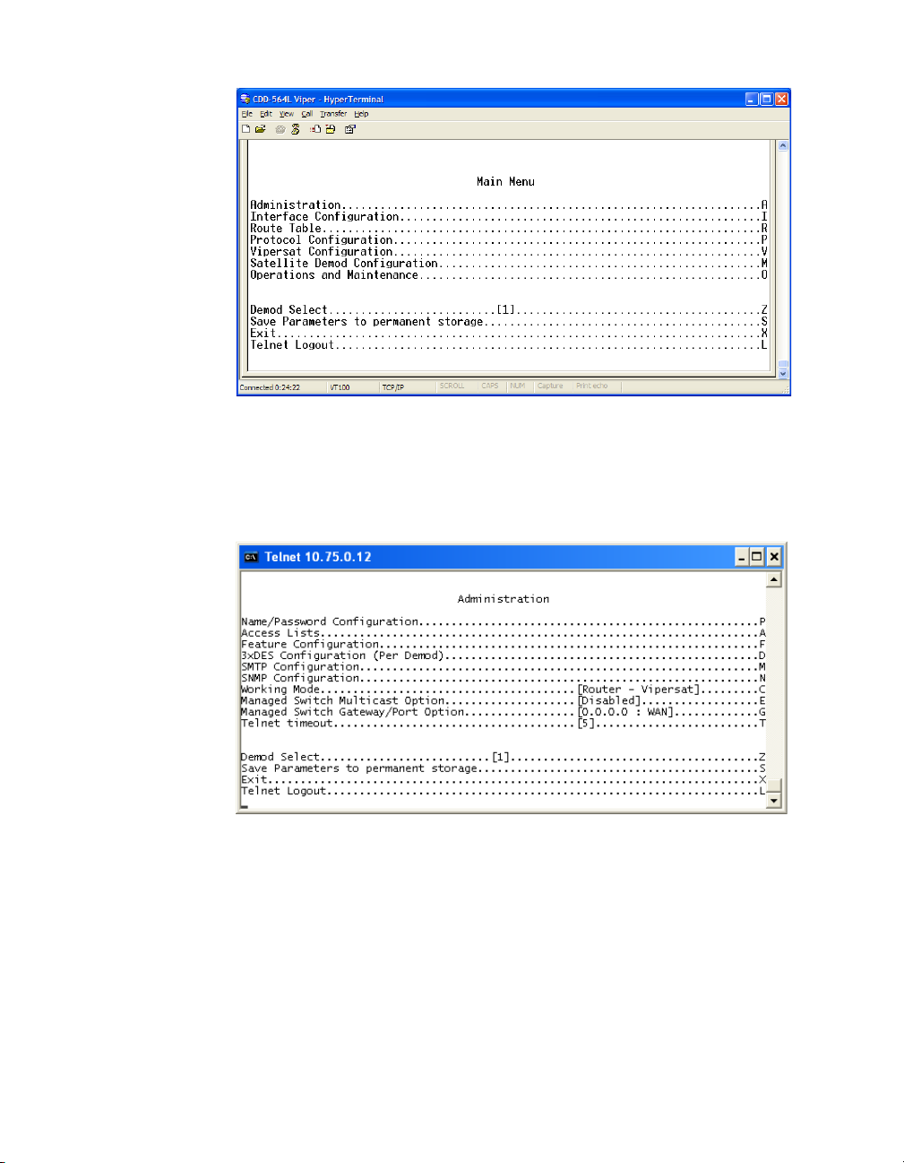
1. From the Main Menu shown in figure 2-1, select the Administration
command by entering A at the command prompt.
Chapter 2 - Quick Start Configuration 2-3
Page 26
Initial Configuration MN/22137, rev 1
Figure 2-1
Main Menu screen
2. From the Administration screen shown in figure 2-2, select the Features
Configuration command by entering F at the command prompt.
Figure 2-2
Administration screen
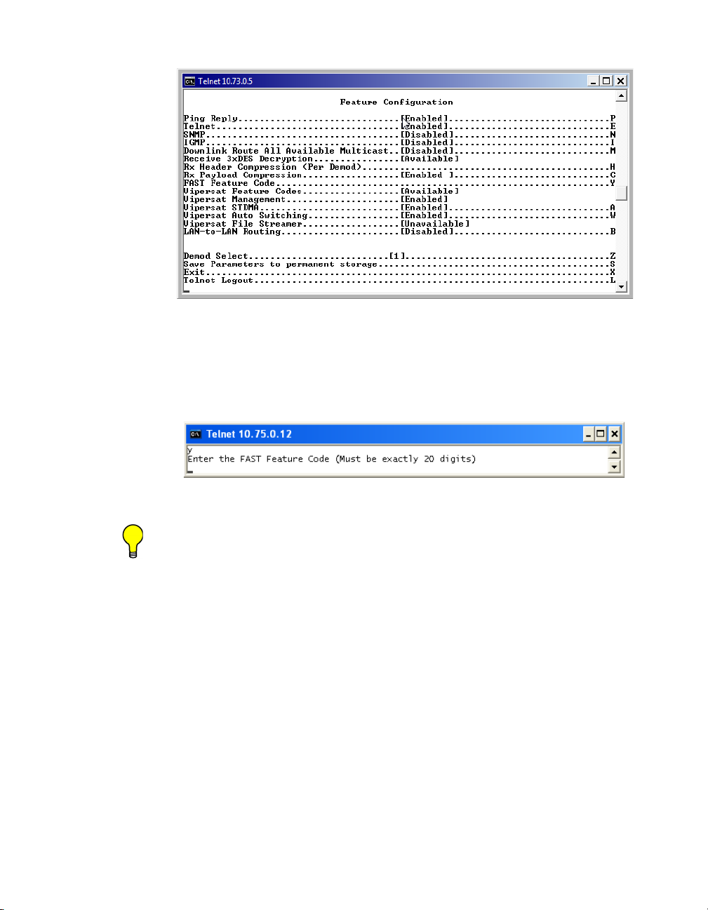
3. From the Feature Configuration menu shown in figure 2-3, verify
whether or not the Vipersat Feature Codes are Available (appears as
shown in the figure). These codes are entered prior to shipment from the
factory; however, if the codes display as Unavailable, they will have to be
re-entered.
2-4 Vipersat CDD-56X Series User Guide
Page 27
MN/22137, rev 1 Initial Configuration
Figure 2-3
Feature Configuration screen
To enter the feature code, enter Y at the command prompt, then enter the 20
digit FAST Feature Code, as shown in figure 2-4.
Figure 2-4
Tip: The network administrator will have the FAST Feature codes. These are
generated and stored by the unit serial number for the target CDD-56X.
The target unit’s serial number can be found on the rear of the unit
chassis.
FAST Feature Code dialog
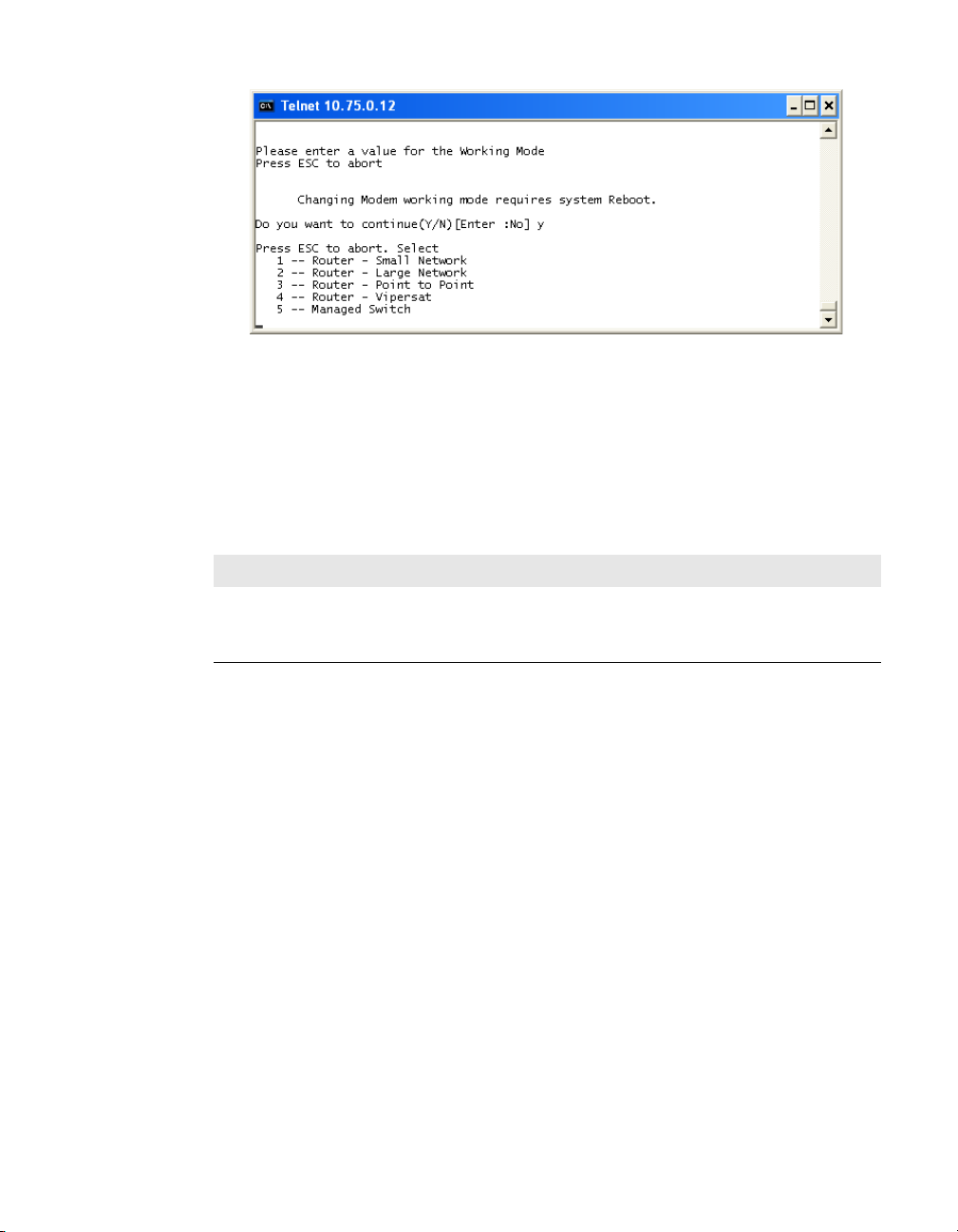
4. After entering the FAST Feature code, return to the Administration screen,
shown in figure 2-2, and ensure that the Working Mode is set to Router-
Vipersat.
If it is not, enter C and change the setting by selecting 4, as shown in
figure 2-5. The unit will reboot automatically in order to implement the
change for this setting.
Chapter 2 - Quick Start Configuration 2-5
Page 28
Initial Configuration MN/22137, rev 1
Figure 2-5
Working Mode dialog
5. When the reboot is completed, return to the Feature Configuration menu
and configure the settings for Vipersat STDMA and Auto Switching
according to the table below.
Table 2-2
Unit Role Vipersat STDMA Auto Switching
Hub Enabled Enabled (optional) Enabled
Hub Expansion Enabled Disabled Disabled
Remote Expansion Enabled Disabled Disabled
Vipersat Feature Configuration
6. Save the settings to flash by entering S at the command prompt.
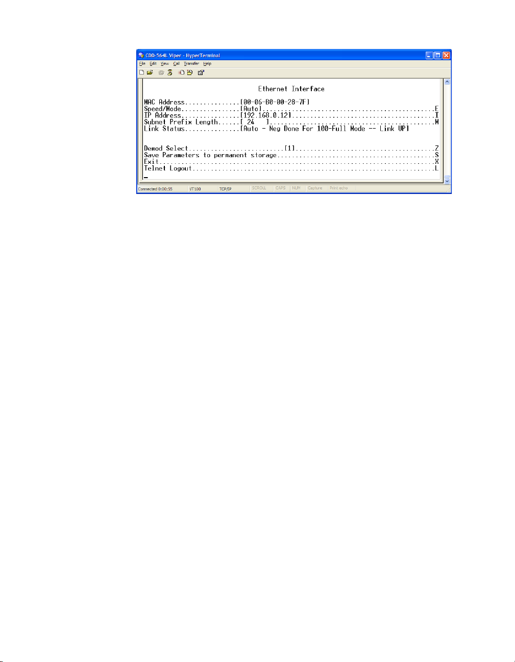
Set the IP Address
1. From the Main Menu, enter I to access the Interface Configuration menu
screen, then enter E to access the Ethernet Interface screen (figure 2-6).
2. Enter I at the command prompt, and enter the IP address for this unit.
2-6 Vipersat CDD-56X Series User Guide
Page 29
MN/22137, rev 1 Initial Configuration
Figure 2-6
Ethernet Interface screen
3. Save the settings to flash by entering S at the command prompt.
Configure the Route Table
Routing in a Vipersat Network
CDD-56X Demodulator Routers operating in Vipersat mode do not use the
small or large network described in the CDD-564L Installation and Operation
Manual. There is no HDLC address in a Vipersat network; instead, the
CDD-56X role designation — Hub or Remote, Expansion unit or not — determines routing rules that prevent multicast loops. This simplifies the configuration of a Vipersat network.
Because satellite networks are often used as extensions for access to services
such as the Internet or the PSTN, they lend themselves quite readily to private
addressing. For example, to provide Internet access to the satellite network, only
the Hub requires a public IP address in order for the entire satellite network that
is controlled by the Hub to have access to the Internet backbone. Utilizing
Network Address Translation (NAT), the administrator can effectively address
the network using a minimum number of static route statements.
Example:
The IP address 172.16.0.0 is the private address network number for class B
networks. If there is a router at the Hub with a connection to the Internet, the
operator can define the local network as a class B. If the operator splits the Class
B in half and points the upper half toward the satellite there will be over 16000
usable addresses at the Hub as well as at the Remotes. For details on IP addressing, refer to Appendix A, "Network Addressing".
Chapter 2 - Quick Start Configuration 2-7
Page 30

Initial Configuration MN/22137, rev 1
By putting the one route statement “Remotes 172.16.128.0/17 Wan to Sat” in
the TDM Hub modem, and by using the route statement “GW 0.0.0.0/0 Wan to
Sat” at each of the remote modems, the network will successfully route packets.
The remotes can then be sub-netted as class C networks or below. Additional
routers at the remotes can be added for unusually large sites, allowing an additional layer of NAT without requiring any more explicit routing within the
Vipersat Modem/Routers.
Refer to the CDD-564L Installation and Operation Manual for additional information on entering routes.
Creating the Routes
The following procedure outlines the basic route structure that the target
CDD-56X will require for its role in the network. One of the key routes that
must be created is a gateway address for routing the data traffic that is received
by the unit.
1. From the Main Menu shown in figure 2-1, select Route Table by entering
R at the command prompt.
2. From the Configuring the Route Table screen shown in figure 2-7, enter
1 at the command prompt to set the first route that will define the default
gateway.
In a Hub configuration, the default gateway will typically point to a router
on the same LAN as the CDD-56X Hub unit.
In a Remote configuration, the default route will typically point to the
satellite modem used for communications back to the Hub.
3. When prompted, enter the Route Name (GW), the IP Address, the
Number of Bits in the subnet mask, the Route Interface (Ethernet or Sat-
ellite), and the Next Hop address. The system administrator can supply
this information, if necessary.
In a Hub role, for example, enter the name of the route (e.g., GW), enter
0.0.0.0 for the destination IP address and 0 for the mask, enter E for
Ethernet interface, then enter the IP address of the appropriate router or
modem for the next hop.
2-8 Vipersat CDD-56X Series User Guide
Page 31

MN/22137, rev 1 Initial Configuration
NOTE
Figure 2-7
Configuring the Route Table screen
4. Enter S at the command prompt in figure 2-7 to save the settings to flash.
Set the Satellite Demod Configuration
1. Enter M from the Main Menu, then enter C from the Satellite
Demodulator menu to access the Configuration screen.
2. Enter R to access the Rx Configuration screen shown in figure 2-8. Set
the Rx parameters for Frequency, Data Rate, FEC, Code Rate, and
Modulation as specified by the network administrator.
The Receive parameters must be set for each Demod. Enter Z at the command prompt to select the desired Demod, then set the Receive parameters
for that Demod. Repeat for each Demod.
Note: Only Turbo Product Coding is acceptable for FEC when the CDD-56X is
running in Vipersat mode.
Chapter 2 - Quick Start Configuration 2-9
Page 32

Initial Configuration MN/22137, rev 1
Figure 2-8
Rx Configuration screen
3. Save the settings to flash by entering S at the command prompt.
Set the Vipersat Configuration
1. Enter V at the Main Menu command prompt (figure 2-1) to select the
Vipersat Configuration menu shown in figure 2-9.
Figure 2-9
2-10 Vipersat CDD-56X Series User Guide
Vipersat Configuration screen (Hub)
Page 33

MN/22137, rev 1 Initial Configuration
2. Enter R at the command prompt to toggle the Unit Role to either Hub or
Remote.
This parameter will determine the role the target CDD-56X will perform in
the network and what type of commands and functions it will receive from
the VMS.
3. Enter E to set the Expansion Unit value to either Yes or No.
When configured as an Expansion unit, either as a Hub (switched) or as a
Remote (mesh), the CDD-56X is set up so that all Demods are in SCPC
mode and available as resources for dedicated communications with the
other end of the satellite link.
4. Enter B at the command prompt to set the Network ID.
The Network ID that is assigned to the unit defines to what network the
target CDD-56X will belong. All units used in a network will have the
same Network ID. This parameter is used by the VMS to identify units
common to a network and allows the VMS to manage multiple networks,
each with its own unique network ID number.
5. Enter N at the command prompt to set the Unit Name.
6. Enter V at the command prompt to set the Receive Multicast Address.
This IP address is the multicast address assigned to the VMS and to all
units in the network that are managed by the VMS. The Receive Multicast
Address of this CDD-56X must match the Transmit Multicast Address that
has been assigned to the VMS.
7. Enter I at the command prompt to set the Managing IP Address.
The Managing IP Address is the IP address of the VMS server.
8. Management Security (Optional)
If this is an encrypted network, enter K at the command prompt to configure Vipersat Management Security.
9. Enter H to go to the Home State Configuration menu screen, then enter
W to set the current configuration as the Home State.
10. Save the settings to flash by entering S at the command prompt.
This completes the initial configuration of a CDD-56X from the factory default
settings to a functioning, Vipersat-enabled unit. Additional configuration
parameters must be set depending on the network requirements for a specific
application.
Chapter 2 - Quick Start Configuration 2-11
Page 34

Initial Configuration MN/22137, rev 1
Refer to Chapter 3, “Using the Command Line Interface (CLI)”, for additional
details on configuring the target Vipersat CDD-56X.
2-12 Vipersat CDD-56X Series User Guide
Page 35

C
HAPTER
USING THE COMMAND LINE INTERFACE
(CLI)
General
This chapter describes the use of the CLI for configuring and monitoring the
CDD-56X Demodulator/Router in a Vipersat network. Each CLI screen related
to a CDD-56X operating in Vipersat mode is presented, along with a detailed
description of the available commands. For descriptions of all other screens,
refer to the CDD-564L L-Band Quad Demodulator Installation and Operation
Manual.
Access to the CLI is provided through either the Console port (local, RS-232)
or the 10/100BaseT Ethernet Traffic port (Telnet, IP). Access via Telnet
requires login with password, Console access does not require login. The
screens presented in this document are as they appear when the CDD-56X is
accessed using Telnet.
When a Telnet terminal connection is made, the CDD-56X responds with a
Login prompt. The factory defaults are:
Login: comtech
Password: comtech
Once the operator has logged in, the Main Menu shown in figure 3-1 is
displayed.
Chapter 3 - Using the Command Line Interface (CLI) 3-1
Page 36

Ge n er al MN/22137, rev 1
Common Screen Commands
The following commands appear on each of the menu screens:
Demod Select
Some feature configurations apply to the CDD-56X as a unit, others are set on a
per Demod basis. This command (enter Z) allows the selection of one of the
two (CDD-562L) or four (CDD-564/564L) Demodulators.
Save Parameters to Permanent Storage
To Save the current parameter settings to permanent storage, enter S at the
command prompt. This command saves all data that has been entered from any
of the CLI screens since the last save was executed. Exiting a screen without
saving after parameters have been changed does not mean that the changes are
not applied. However, if these changes are not saved prior to a system reset or
power cycle, they will be lost.
Exit
To Exit the current menu screen and return to the previous screen in the menu
tree, enter X at the command prompt.
Telnet Logout
Enter L at the command prompt to Logout of the Telnet session. This command
appears only when connected via Telnet.
3-2 Vipersat CDD-56X Series User Guide
Page 37

MN/22137, rev 1 Me n u D e s cr i p t io n s
NOTE
Menu Descriptions
This section details the CLI menus and associated screens, and briefly discusses
the function of each of the commands available on each menu.
Main Menu
The Main Menu, shown in figure 3-1, allows configuring both the Demodulator and Router functions of the target CDD-56X.
Note: The menu item Vipersat Configuration shown in figure 3-1 will only be
displayed if the target CDD-56X has had the Vipersat option enabled as
described in the section “Setting Vipersat CDD-56X Operating Parameters” on page 2-3.
Figure 3-1
Main Menu screen
A Vipersat CDD-56X is normally shipped with the Vipersat option enabled.
The CDD-56X configuration can be determined by whether or not the command
line Vipersat Configuration is displayed on the menu, as shown in Figure 3-1.
Administration
The Administration menu provides access to the major Vipersat CDD-56X
features and commands. Entering an A at the prompt in the Main Menu, shown
in figure 3-1, displays the Administration screen shown in figure 3-2.
Chapter 3 - Using the Command Line Interface (CLI) 3-3
Page 38

Me n u De sc ri pt io ns MN/22137, rev 1
NOTE
Figure 3-2
Administration screen
Ensure that the Working Mode is set to Router-Vipersat.
If it is not, enter C at the command prompt and change the setting by selecting
4, as shown in figure 3-3. The unit will reboot automatically in order to implement the change for this setting.
Figure 3-3
Note: If the Router-Vipersat option does not appear as a selection, the Vipersat
Feature Code has not yet been entered into this unit. Input the Vipersat
code as described in the next section..
Working Mode dialog
From the Administration menu, enter an F at the prompt to display the Feature
Configuration screen shown in figure 3-4.
3-4 Vipersat CDD-56X Series User Guide
Page 39

MN/22137, rev 1 Me n u D e s cr i p t io n s
NOTE
Feature Configuration
Figure 3-4
Feature Configuration screen
The Feature Configuration screen shown in figure 3-4 allows the Enabling
and Disabling of the major Vipersat CDD-56X features.
Use this screen to enable and disable Vipersat features such as:
• Vipersat STDMA — Burst mode operation
• Vipersat Auto Switching — Allows switching to SCPC mode
• Vipersat File Streamer — Rapid file transfers over satellite network
Note: These Vipersat features must be Enabled or Disabled using this menu.
They are not accessible from the Vipersat Configuration menu.
Vipersat Feature Codes
From the Feature Configuration menu, verify whether or not the Vipersat
Feature Codes are Available (appears as shown in figure 3-4). These codes are
entered prior to shipment from the factory; however, if the codes display as
Unavailable, they will have to be re-entered. To enter the FAST Feature code,
enter Y at the command prompt.
The Vipersat FAST Feature Codes can be entered as 20 hexidecimal digits at
the command prompt as shown in figure 3-5.
Chapter 3 - Using the Command Line Interface (CLI) 3-5
Page 40

Me n u De sc ri pt io ns MN/22137, rev 1
NOTE
Figure 3-5
Tip: Contact either the network administrator or Comtech Vipersat Networks
Customer Support to obtain the Feature codes. A convenient option is to
use the Vipersat Vload utility to manage Feature codes.
FAST Feature Code dialog
Vipersat Management
This item is an information-only display, and indicates whether Vipersat
Management is Enabled or Disabled in the target CDD-56X. Activation of the
Vipersat Feature Code automatically enables the Vipersat Management feature.
Caution: This command must be Enabled in order to utilize any of the Vipersat
capabilities of the CDD-56X.
Vipersat STDMA
In order to utilize the Vipersat STDMA feature (burst mode) in the target
Vipersat CDD-56X, this feature must be Enabled. Enter A at the command
prompt to toggle On or Off.
Refer to table 2-2 for the relationship between Unit Role and STDMA. This
feature should only be enabled for a unit that is used as a Hub with no expansion
(i.e., a Burst Controller).
Note: Although the CDD-56X has multiple demods, STDMA is configurable for
only one demod. When this parameter is enabled, Demod 1 is set for
STDMA mode and the remaining demods are set for SCPC mode.
Vipersat Auto Switching
The Vipersat Auto Switching feature allows the CDD-56X to automatically
adjust to varying bandwidth demands in the Vipersat network by switching
between STDMA and SCPC connections. This feature should only be enabled
for a unit that is used as a Hub with no expansion, and that will be required to
send switching requests to the VMS in response to either traffic type (Application switching) or network traffic loads (Load switching). Refer to table 2-2 for
the relationship between Unit Role and Auto Switching.
3-6 Vipersat CDD-56X Series User Guide
Page 41

MN/22137, rev 1 Me n u D e s cr i p t io n s
To activate the Vipersat Auto Switching capabilities of the target CDD-56X,
toggle the Auto Switching command to Enabled by entering W at the command
prompt.
See the section “STDMA/SCPC Automatic Switching” on page 3-32 for more
details on the use of this feature. For additional information, refer to Appendix
B, “Automatic Switching”.
Vipersat File Streamer
Vipersat File Streamer (VFS) is an optional feature that allows rapid file transfers over the satellite network between host PCs that are running the client VFS
application. To activate the Vipersat File Streaming capabilities of the
CDD-56X, toggle this command to Enabled by entering R at the command
prompt.
Once the parameters on the Feature Configuration screen have been set as
desired, return to the Main Menu and enter the V command to display the
Vipersat Configuration screen shown in figure 3-6.
Chapter 3 - Using the Command Line Interface (CLI) 3-7
Page 42

Vi p er sa t C o nf ig ur at io n MN/22137, rev 1
Vipersat Configuration
Entering V at the prompt from the CDD-56X Main Menu shown in figure 3-1
displays the Vipersat Configuration menu shown in figure 3-6.
Figure 3-6
This menu lists the available commands for configuring a Vipersat CDD-56X.
Note that for the Hub unit only, the command Primary Heart Beat is displayed
in the Vipersat Configuration screen. For the Remote unit only, the status of the
Home State Revert setting is displayed.
Each of these commands is explained in the following sections.
Vipersat Configuration screen (Hub)
STDMA Mode
The STDMA Mode parameters for this CDD-56X are accessed by entering T at
the Vipersat Configuration screen command prompt.
The items in the STDMA menu will vary depending on the function the target
CDD-56X performs in the network (Hub or Remote) and the Hub Type that is
designated. The STDMA screen shown in figure 3-7 is from a CDD-56X serving as a Hub with STDMA in the network. The Hub Type is designated as
Fixed, in this example.
For comparison, the STDMA screen for a CDD-56X operating in SCPC mode
(either as a Hub expansion unit or as a Remote mesh unit) is shown in
figure 3-8. Note that some of the command items differ between these two
screens, and most of the items on the SCPC menu are information-only display..
3-8 Vipersat CDD-56X Series User Guide
Page 43

MN/22137, rev 1 Vi pe r s a t C o n f ig u r a t i o n
Figure 3-7
Figure 3-8
STDMA screen (Hub, STDMA, Fixed type)
STDMA screen (Hub/Remote, SCPC)
STDMA
This menu item is read-only and shows the current state of STDMA in the
CDD-56X. In order to change the STDMA state, refer to the section “Feature
Configuration” on page 3-5.
Chapter 3 - Using the Command Line Interface (CLI) 3-9
Page 44

Vi p er sa t C o nf ig ur at io n MN/22137, rev 1
STDMA Tx Rate
This menu item shows the STDMA Transmit Rate (in bps) of data that the
CDD-56X receives. This item is read-only and cannot be modified in this menu.
Hub Type
This menu item is only displayed if the CDD-56X is being used as a Hub in the
network, and provides the functionality for the STDMA Burst Controller.
Vipersat STDMA has six modes of operation:
• Fixed — all remotes get the same data slot time (slot size) in the cycle,
regardless of activity. Cycle time is fixed also.
• Dynamic Slot — data slot time of remotes vary according to activity,
cycle time does not.
• Dynamic Cycle — slot time and cycle time vary according to activity of
remotes.
• GIR (Guaranteed Information Rate) — each remote always has at least the
minimum data slot size when needed, and cycle time is variable up to a
maximum of one second.
• Entry Channel — remotes run in SCPC mode, but STDMA is used for
maintenance and control channel.
• ECMv2 — utilizes a modified slotted Aloha method for remotes to
establish registration in the network and obtain the means for switching
into SCPC mode.
The Hub can be configured to operate as one of the six types by entering a T at
the command prompt to display the dialog shown in figure 3-9.
Figure 3-9
Hub Type prompt
This selection determines whether available bandwidth will be a static (fixed)
assignment, or whether bandwidth allocation will be dynamic with automatic
switching to dynamically optimize bandwidth utilization.
3-10 Vipersat CDD-56X Series User Guide
Page 45

MN/22137, rev 1 Vi pe r s a t C o n f ig u r a t i o n
Refer to Appendix B, “Automatic Switching”, for additional information on
how each of the bandwidth allocation modes functions and the parameters used
to calculate the commands for each mode.
1 – Fixed
In the Fixed mode, all remotes have the same data slot size regardless of type of
traffic or load. This mode minimizes the amount of jitter between remote transmission times, and is useful for tuning STDMA as well as for troubleshooting
purposes.
2 – Dynamic Slot
In the Dynamic Slot mode, slot size is adjusted each cycle depending on the
activity during the previous cycle. The slot size for each remote is computed
based on the time (at the current data rate) needed to transmit all the bytes in
queue. If the result is less than the minimum slot size or more than the maximum slot size, the slot is adjusted accordingly. This mode allows the burst
controller to provide additional slot time in the cycle to remotes with higher
traffic demands, and helps to alleviate congestion.
3 – Dynamic Cycle
In the Dynamic Cycle mode, available bandwidth is allocated to remotes
proportionally based on their current bandwidth needs. The bandwidth requirements are determined by the number of bytes in queue for each remote divided
by the total number of bytes in queue for all remotes, and results in the percentage of bandwidth to allocate for each remote. This mode provides improved
efficiency of STDMA due to faster cycle times during periods of light traffic
demands, thus providing minimum latency for the current load.
4 – GIR
In the GIR mode, the initial computed slot size value is the same as in the
Dynamic Cycle mode except there is no maximum limit. After all remotes have
been assigned slots, the burst map is checked to see if the total cycle length
exceeds one second. If not, then all requirements are satisfied and the burst map
is complete. However, if the cycle is greater than one second, then the slots are
adjusted proportionally so that all remotes receive at least their guaranteed rate
plus whatever excess is still available.
GIR mode allows guaranteed information rates to be set for each remote in the
group. When the one second restriction is exceeded, remotes without a specified
GIR are reduced to the global minimum slot size and the remaining bandwidth
is distributed to remotes that have been assigned a GIR rate, thus ensuring additional bandwidth to these units when needed.
Chapter 3 - Using the Command Line Interface (CLI) 3-11
Page 46

Vi p er sa t C o nf ig ur at io n MN/22137, rev 1
NOTE
Note: GIR allocations are restricted so that assigned GIR totals cannot exceed
the available bandwidth. This ensures proper bandwidth allocation when
the network is overloaded.
The GIR setting for each Remote is specified using the STDMA Remote Policies screen (refer to the section “Set Remote Policies” on page 3-24). When
combined with Auto switching, GIR allows trigger points to be set where the
Remote will jump out into SCPC mode. This is done using the Load Switch
setting. Note that, for this function, Auto switching must be Enabled on this
Hub unit, and corresponding Remote modems must be configured with Auto
switching and Load switching Enabled. Also, the settings for Step Up and Step
Down Threshold values should be adjusted as necessary for the application.
5 – Entry Channel
The Entry Channel mode provides remotes in the group with a shared channel
in which they can gain initial access to the network. Since very small STDMA
data rates are required in this configuration, a larger number of remotes can
share the cycle. As soon as the Hub receives an STDMA ACK from the
Remote, it initiates an immediate switch to SCPC mode based on the policy set
for that Remote. Note that the switch occurs as soon as the Hub receives an
ACK even though there may not be traffic at that time. The persistence of the
link will be determined by the unit’s flag settings.
When choosing Entry Channel as the Hub type for the STDMA Controller, the
Auto switching feature must be Enabled on this Hub unit, and switching policies
for the remotes must be configured (refer to the section “Set Remote Policies”
on page 3-24). Corresponding Remote modems must be configured with Auto
switching and Load switching Enabled. Note that the settings for Step Up and
Step Down Threshold values should be adjusted as necessary for the application.
This mode is designed to accommodate the needs of a Remote that will not be
continuously connected to the network, but which has the need to be able to
make an on-demand connection when required, such as in a mobile application.
In the event of a power outage, Entry Channel provides a bandwidth-efficient
method for remotes with low latency requirements to re-enter the network once
power is restored.
6 – ECMv2
The ECMv2 (Dynamic Entry Channel) mode is very similar to the regular
Entry Channel mode. However, the associated limitation in the number of
Remotes is eliminated via the modified slotted Aloha method that is utilized for
this mode. No cycle is used, and a Remote List is not necessary.
The Hub broadcasts an anouncement message to all Remotes that are tuned to
receive it that provides the available slots and the tuning parameters for trans-
3-12 Vipersat CDD-56X Series User Guide
Page 47

MN/22137, rev 1 Vi pe r s a t C o n f ig u r a t i o n
mitting back to the Hub. The Remotes transmit on a contention basis and should
a collision occur, the Remote will back off for a specified period and try again.
Once it obtains one of the available slots, the Remote will hold onto the slot
until it registers with the VMS and receives assignment into dSCPC, or until all
necessary transactions are completed. The slot is then released for use by
another Remote unit that is attempting to enter the channel.
Remotes can be set to one of four operating modes—Disable, Offline, Wait, and
Online—from the ECMv2 Mode command in the STDMA menu. In addition,
commands for setting parameters to accomodate any mismatches between the
Hub LNB and the Remote BUCs are presented: LNB LO Frequency (Hub),
BUC LO Frequency (Remote), and Satellite Conversion Frequency.
ECMv2 Mode
This menu item appears for Hub expansion and Remote expansion units operating in ECMv2 only.
Each unit can be set to a designated mode of operation in ECM:
• Disable – the ECM function for this unit is disabled.
• Offline – the unit will not transmit (muted).
This mode may be chosen for radio silence applications.
• Wait – the unit will register with the controller and remain in the ECM
wait queue without assignment for switching into dSCPC mode. This
mode may be chosen by operators who wish to manually control (via
diagnostic switch) when a unit is to be switched and utilize bandwidth
from the pool.
• Online – the unit will register with the controller and request dSCPC
bandwidth for switching.
In order for a unit to automatically switch into SCPC mode and pass data traffic,
the ECMv2 Mode must be set to Online.
Figure 3-10
Tip: For purposes of commissioning the terminal with a continuous carrier, the
Entry Channel mode can be set temporarily to Disable. Once this process
is completed, set the Remote back to the desired mode for normal
operation.
Chapter 3 - Using the Command Line Interface (CLI) 3-13
ECMv2 Mode prompt
Page 48

Vi p er sa t C o nf ig ur at io n MN/22137, rev 1
NOTE
Group ID
The STDMA Group ID number defines a group of equipment (including
CDD-56X Hub and Remote units) that will respond to the output of a single
STDMA burst controller. This group is addressable within a network which, in
turn, is defined by the Network ID number assigned to the CDD-56X.
Allocation of bandwidth is shared among the remotes in an STDMA group.
Depending on the number of remotes in a network, a Hub may have multiple
burst controllers, each with its own set of remotes. This is accomplished by
assigning a unique Group ID number to each controller and its associated
remotes.
Note: The STDMA Group ID number and the Network ID number are indepen-
dent. There can be multiple STDMA groups within a single network.
The target CDD-56X Group ID can be modified by entering an I at the
command prompt to display the dialog shown in figure 3-11.
Figure 3-11
Group ID prompt
STDMA Max Power Hunt
This menu item appears for Remote modems only.
Should link reception from a Remote be incorrect or impaired (e.g., poor environmental conditions), the STDMA Max Power Hunt feature is an option on
the Remote modem that automatically adjusts the Remote transmit power to
ensure that burst map acknowledgements from that unit are received by the Hub
burst controller. When enabled, the burst controller sets a flag in the burst map
that indicates it is not receiving acknowledgements from an enabled Remote.
When the Remote receives the burst map, it will see the flag and automatically
increase power up to the maximum value specified with this parameter (3, 6, or
9 dB) above the default or Home State setting. If this closes the link, the burst
controller will clear the flag. Note that if the dB increase is more than is necessary, DPC will make a down adjustment to the appropriate level and this adjustment will be added to the DPC Offset.
3-14 Vipersat CDD-56X Series User Guide
Page 49

MN/22137, rev 1 Vi pe r s a t C o n f ig u r a t i o n
NOTE
This feature option is Enabled/Disabled by entering H at the command prompt.
Figure 3-12
STDMA Max Power Hunt prompt
Low Data Rate Fast Acquisition
Configurable on a Hub Burst Controller only.
This menu item is a toggle used to Enable or Disable the Vipersat Burst Fast
Acquisition Timing (BFAT) feature that functions at low data rates (64 kbps to
256 kbps). This feature allows for significantly faster acquisition times at these
data rates, even with higher noise, resulting in improved efficiency of the shared
STDMA channel. Since signal lock is faster at higher data rates, BFAT is not
active above 256 kbps.
Entering A at the command prompt will toggle this feature On or Off.
This feature requires Router firmware version 1.5.3 or later. The unit configuration must be set for operation at either 3/4 QPSK or .95 QPSK in order to utilize
BFAT.
Note: Use of BFAT is NOT recommended with ECMv2.
When this feature is enabled with any other STDMA allocation method,
the Preamble parameter becomes fixed (not settable by the user) and
this value is automatically determined by the system—appears as
display only in the CLI; not displayed in the Parameter Editor.
Burstmap Multicast IP
This menu item is used to define the IP address for the Burstmap Multicast that
is sent out by the STDMA burst controller at the Hub to all of the associated
remotes in that group. This address must be the same for all members of the
goup. The burstmap is a proprietary message sent from the Hub to all remotes,
at regular intervals, specifying the relative start time and duration for each
terminal to transmit.
To change the current address, enter N at the command prompt to display the
dialog shown in figure 3-13.
Chapter 3 - Using the Command Line Interface (CLI) 3-15
Page 50

Vi p er sa t C o nf ig ur at io n MN/22137, rev 1
Figure 3-13
Burstmap Multicast IP prompt
Outbound IP
This menu item, which appears for all Hub configurations, displays the current
Outbound IP address. This specifies the Hub device that is supplying the TDM
outbound to the satellite (typically a CDM-570L). Specifying this address is
necessary for Hub configurations that utilize a burst controller (such as the
CDD-56X) that is a separate device from the TDM modem.
This address must also be defined when using the following features:
• DPC
• SOTM
The Outbound IP address will be the same as the burst controller IP address
when the burst controller and the TDM modem are the same device.
To define the TDM outbound address, enter O at the command prompt to
display the dialog shown in figure 3-14.
Figure 3-14
Outbound IP prompt
Cycles Per Burst Map
This menu item, which appears for Hub types Fixed, Dynamic Slot, and Entry
Channel, displays the number of spin cycles that will occur prior to each broad-
cast of the Burst Map by the burst controller to the remotes. One cycle is the
amount of time it takes for all remotes in a group to burst on the common channel. The burst map provides each remote with its allocated bandwidth and position in the cycle.
3-16 Vipersat CDD-56X Series User Guide
Page 51

MN/22137, rev 1 Vi pe r s a t C o n f ig u r a t i o n
NOTE
For Dynamic Cycle and GIR configurations, the number of cycles is automatically set to one in order to ensure optimum performance for these Hub types.
This parameter can be modified by entering a C at the command prompt to
display the dialog shown in figure 3-15.
Figure 3-15
Cycles per Burst Map prompt
Slot Guardband
This menu item, which appears for all Hub configurations, displays the current
length of the Slot Guardband in milliseconds and in bytes for the remotes in the
group. The Slot Guardband is the amount of time between the point when one
remote completes transmitting data and the point when the next remote in the
cycle begins transmitting. This prevents the remote from overrunning the next
terminal in the cycle. The setting for this parameter should be obtained using the
Vipersat STDMA calculator.
Tip: For a copy of the latest Viper Calculator, contact a Comtech Vipersat
Networks representative.
This value can be modified by entering a G at the command prompt to display
the dialog shown in figure 3-16 and entering a new value.
Figure 3-16
Note: The value entered at the command line in figure 3-16 is in milliseconds.
The corresponding value expressed in bytes is calculated by the
Chapter 3 - Using the Command Line Interface (CLI) 3-17
Slot Guardband prompt
Page 52

Vi p er sa t C o nf ig ur at io n MN/22137, rev 1
NOTE
CDD-56X based on the STDMA transmit bit rate as shown in the menu
in figure 3-7.
Slot Preamble Length
This menu item, which appears in all Hub and Remote configurations, displays
the current Slot Preamble size in milliseconds and bytes for the remotes in the
group. The Slot Preamble is the period between when the remote begins to
transmit (sends an ACK) to the Hub and when the first data packet is sent. This
allows time for signal lock to occur before data is sent, thus preventing data
loss. Higher data rates allow for a shorter preamble, since it is easier to achieve
signal lock. The setting for this parameter should be obtained using the Vipersat
STDMA Calculator.
Tip: For a copy of the latest Viper Calculator, contact a Comtech Vipersat
Networks representative.
Note: When either the BFAT feature is enabled or the Hub Type is ECMv2, the
preamble length is set automatically for the unit.
On a Hub unit, entering a P at the command prompt allows changing the preamble duration in milliseconds.
Figure 3-17
Slot Preamble Length prompt
Slot Data Length
This menu item, which appears for Fixed, Entry Channel, and ECMv2 Hub
types, displays the current Slot Data Length in milliseconds and bytes for the
remotes in the group, and represents the amount of data that can be transmitted
or received in one spin of the STDMA cycle by each of the remotes belonging
to that group. This is the amount of time that the remote is provided to send data
in the cycle.
To change this setting, enter B at the command prompt to display the dialog
shown in figure 3-18.
3-18 Vipersat CDD-56X Series User Guide
Page 53

MN/22137, rev 1 Vi pe r s a t C o n f ig u r a t i o n
Figure 3-18
Slot Data Length prompt
Nominal Data Length
This menu item, which appears for Dynamic Slot Hub type, displays the Nominal slot Data Length in milliseconds and bytes for the remotes in the group,
and represents the approximate amount of data that can be transmitted or
received in one spin of the STDMA cycle by each of the remotes belonging to
that group. This is the amount of time that the remote is provided to send data in
the cycle.
Entering a B at the command prompt brings up the dialog shown in figure 3-19
allowing changing the nominal data length, in milliseconds, for the target
CDD-56X.
Figure 3-19
Nominal Data Length prompt
Maximum Data Length
This menu item, which appears for Dynamic Cycle Hub type, displays the
current Maximum Data Length in milliseconds and bytes for the remotes in
the group, and represents the maximum amount of data that can be transmitted
or received in one spin of the STDMA cycle by each of the remotes belonging
to that group. This is the maximum amount of time that the remote is provided
to send data in the cycle.
Chapter 3 - Using the Command Line Interface (CLI) 3-19
Page 54

Vi p er sa t C o nf ig ur at io n MN/22137, rev 1
To change this setting, enter B at the command prompt to display the dialog
shown in figure 3-20.
Figure 3-20
Maximum Data Length prompt
Minimum Data Length
This menu item, which appears for Dynamic Slot, Dynamic Cycle, GIR, and
Entry Channel Hub types, displays the current Minimum Data Length in milli-
seconds and bytes for the remotes in the group, and represents the minimum
amount of data that can be transmitted or received in one spin of the STDMA
cycle by each of the remotes belonging to that group. This is the minimum
amount of time that the remote is provided to send data in the cycle.
Entering an M at the command prompt brings up the dialog shown in
figure 3-21 allowing the minimum data length, in milliseconds, to be changed
for the target CDD-56X.
Figure 3-21
Minimum Data Length prompt
Total Slot Count
This menu item appears for Hub units operating in ECMv2 only.
3-20 Vipersat CDD-56X Series User Guide
Page 55

MN/22137, rev 1 Vi pe r s a t C o n f ig u r a t i o n
This parameter defines the number of time slots per cycle available for assignment to the Remotes in queue that are to be switched from ECM into dSCPC.
These are the Remotes that are tagged for Online mode. By design, ECM works
on a contention basis, with the number of slots being some fraction of the total
number of Remotes. In order for this ratio to be optimized, a Vipersat calculator
is available to determine this setting.
Tip: Contact a Comtech Vipersat Networks representative for a copy of the
latest Vipersat ECM Calculator.
Entering R at the command prompt allows changing the slot count.
Valid range is 1 to 255.
Figure 3-22
Total Slot Count prompt
Slot Cycle Length
This menu item is for information only and displays the Slot Cycle Length in
milliseconds and bytes for the remotes in the group. This value represents the
total amount of time—preamble, data length, and guardband—allocated to the
Remote terminal during one spin cycle.
Slot Start in Cycle
This menu item appears in the STDMA screen when the Unit Role is Remote;
however, it is not relevant since a Remote configuration does not enable
STDMA.
Set Remotes
This menu item appears in the STDMA screen when the Unit Role is Hub with
No Expansion, except for Hub Type ECMv2.
Entering an R at the command prompt displays the STDMA Remotes Menu as
shown in figure 3-23. This screen is used to define and make modifications to
the Remotes that belong to the STDMA group for the Hub burst controller, as
well as to display the burst map status information for each Remote.
Chapter 3 - Using the Command Line Interface (CLI) 3-21
Page 56

Vi p er sa t C o nf ig ur at io n MN/22137, rev 1
Figure 3-23
STDMA Remotes Menu screen
Adding a Remote to the STDMA Group
Entering the item number for the Remote demodulator/router brings up the
dialog shown in figure 3-24. A prompt to enter the Name to assign to the
Remote unit appears, followed by a prompt to enter the IP Address for this unit.
Figure 3-24
Remote Name and IP Address prompt
Once a Remote has been added to the group, its Status in the group is displayed
by the use of the following letters:
• U = Used – This Remote is being used in the burstmap.
Once a remote has been added to the STDMA group, this status will
always be displayed.
• B = Burstmap – This Remote is currently in the burstmap.
This status will be displayed unless the remote has been removed (R),
disabled (D), or switched (S) out of the STDMA burstmap.
3-22 Vipersat CDD-56X Series User Guide
Page 57

MN/22137, rev 1 Vi pe r s a t C o n f ig u r a t i o n
• R = Removed – This Remote is currently removed from the burstmap.
When displayed, this status indicates that the Hub has removed this remote
from the burstmap due to a communications fault.
• D = Disabled – This Remote is currently disabled and is not in the
burstmap.
This status will be displayed when a remote is manually disabled by the
operator or administrator.
• S = Switched – This Remote is currently switched into SCPC mode.
When displayed, this status indicates that the VMS has automatically
switched the remote out of the burstmap and into SCPC operation.
• H = Home State Revert – This Remote is not currently receiving burst
maps. When a remote, stuck in SCPC mode by failure to receive a VMS
revert command, sees the burst map with this flag set, it will automatically
revert to its home state and STDMA mode.
• CF – This Remote has not sent an acknowledgement to the burst controller
since it was enabled.
Most commonly, either a B or an S will be displayed, as a typical Remote
will be either Bursting or Switched out to the dSCPC pool.
Base
Entering a B at the command prompt in figure 3-23 allows entering the Remote
number to start displaying remotes in this menu screen. Entering the number 1,
as shown in figure 3-23, displays nine remotes, 1 through 9. If the number 4 had
been entered, the display would show the nine remotes starting with Remote 4
(i.e., remotes 4 through 12).
Figure 3-25
Base Remote Display prompt
Remote Count
The Remote Count menu item in figure 3-23 is an information-only display
showing the total number of Remotes that currently belong to the STDMA
group for this Hub burst controller.
Chapter 3 - Using the Command Line Interface (CLI) 3-23
Page 58

Vi p er sa t C o nf ig ur at io n MN/22137, rev 1
Set Remote Policies
This menu item, which appears for GIR and Entry Channel Hub types, allows
each Remote to be configured for specific data switching conditions.
For Hub STDMA Controllers operating in either GIR or Entry Channel mode,
typical load switching is not the mechanism that performs the transition from
STDMA to SCPC mode due to traffic load. In GIR mode, the Remote is
switched to SCPC as soon as the GIR threshold is reached. In Entry Channel
mode, the Remote is switched to SCPC as soon as the Hub receives the first
transmission from the Remote.
For both GIR and ECM, the event of switching from STDMA to SCPC can only
occur if the SCPC Switch Rate parameter is set to a value greater than 0 (zero).
If the switch rate for a Remote is set to 0 kbps, that Remote will remain in
STDMA mode and will only switch to SCPC mode due to an application switch
or a diagnostic (manual) switch.
Entering P at the STDMA Remotes Menu command prompt displays the
Remote Policies screens shown in figure 3-26 (GIR Hub) and figure 3-28
(Entry Channel Hub).
Figure 3-26
STDMA Remote Policies screen (GIR Hub)
Entering the Remote number at the command prompt in figure 3-26 allows the
Guaranteed Information Rate and the Automatic Load Switch Rate for that
Remote to be set, as shown in figure 3-27. Note that the Available Bandwidth is
displayed for reference in this screen to assist with entering the appropriate
rates. The cycle length for GIR is limited to a maximum of one second.
3-24 Vipersat CDD-56X Series User Guide
Page 59

MN/22137, rev 1 Vi pe r s a t C o n f ig u r a t i o n
Set the Automatic Load Switch Rate to a value greater than the GIR to allow the
Remote to be automatically switched out of STDMA and into SCPC mode
when traffic exceeds the GIR. A Switch Rate of 0 will prevent the Remote from
being switched out of STDMA and into SCPC mode.
Figure 3-27
GIR Remote Policies prompt
The Remote Policies screen for an Entry Channel Hub type allows the SCPC
data rates and switch types to be specified for when the Remotes will switch and
the desired starting points for communications.
Figure 3-28
Entry Channel Switch Rates screen
Entering the Remote number at the command prompt in figure 3-28 allows the
SCPC Data Rate and the Switch Type for that Remote to be set, as shown in
figure 3-29. Switch type 0 corresponds to Load Switching; switch types 64
through 255 are user-defined, and must match VMS policies. When choosing
Load Switching as the Switch Type, the associated Remote must have the Load
Chapter 3 - Using the Command Line Interface (CLI) 3-25
Page 60

Vi p er sa t C o nf ig ur at io n MN/22137, rev 1
Switching feature Enabled (see the section “STDMA/SCPC Automatic Switching” on page 3-32).
Figure 3-29
Remote SCPC Data Rate prompt
The Global SCPC Rate command can be used to set the data rate for all or a
majority of the Remotes. This allows the rate to be entered just once instead of
entering the rate for each Remote individually. Enter G at the command prompt
in figure 3-28.
Figure 3-30
Global SCPC Data Rate prompt
Similarly, the Global Switch Type command can be used to set the switch type
for all or a majority of the Remotes. Enter H at the command prompt.
Figure 3-31
Global Switch Type prompt
Delete Remote
Entering D at the command prompt shown in figure 3-23 brings up the Delete
Remote dialog shown in figure 3-32.
3-26 Vipersat CDD-56X Series User Guide
Page 61

MN/22137, rev 1 Vi pe r s a t C o n f ig u r a t i o n
Figure 3-32
Delete Remote prompt
Enter the number of the Remote CDD-56X at the command prompt to delete it
from the STDMA group for this Hub burst controller.
Enable/Disable Remote
Enter E at the command prompt in figure 3-23 to display the dialog shown in
figure 3-33. The Remotes in the network are displayed, indicating whether each
is currently Enabled (E) or Disabled.
Figure 3-33
Enable/Disable Remote prompt
Enter the number of the Remote at the command prompt to toggle the Remote
from its current Enable/Disable configuration.
In the example screen shown above, both Remotes 1 and 2 are Enabled.
View Remote(s)
Entering V at the command prompt shown in figure 3-23 will display the listing
of Remote(s) that belong to the STDMA group for this Hub burst controller, and
their status, as shown in figure 3-34.
Figure 3-34
Chapter 3 - Using the Command Line Interface (CLI) 3-27
View Remote(s) screen
Page 62

Vi p er sa t C o nf ig ur at io n MN/22137, rev 1
The display is for information only and pressing any key will return the screen
to the menu shown in figure 3-23.
Remove Timeout
Entering R at the command prompt shown in figure 3-23 will display the
Remove Timeout dialog shown in figure 3-35. Note that this menu item shows
the current setting (in seconds) for this parameter.
Figure 3-35
Remove Timeout prompt
The value entered at the command prompt defines the amount of time (in
seconds) with no communication from a Remote to the Hub before that Remote
is removed from the Burst Map. If communications are lost for this specified
period of time, the Remote is removed from the STDMA group, and the bandwidth resources it had been allocated are then made available for use by the
other remotes remaining in the group.
This feature is useful, for example, in an SNG application where a mobile
Remote has finished its assignment and has shut down.
Remove Retry Timeout
Entering T at the command prompt in figure 3-23 will display the Remove
Retry Timeout dialog shown in figure 3-36. Note that this menu item shows
the current setting (in seconds) for this parameter.
Figure 3-36
3-28 Vipersat CDD-56X Series User Guide
Remove Retry Timeout prompt
Page 63

MN/22137, rev 1 Vi pe r s a t C o n f ig u r a t i o n
When a Remote is removed from the group Burst Map, as described in the
section “Remove Timeout” above, entering a value in the Remove Retry Timeout dialog defines the amount of time (in seconds) that is allowed to pass before
a retry attempt is made to return the removed Remote to the group. The Remote
is re-entered into the burst map cycle; if the Remote does not burst back (ACK)
to the Hub burst controller, it is again removed from the Burst Map.
This allows, again using a mobile Remote as an example, shutting down the
Remote at one location, moving it to a new location, and then automatically reestablishing a connection to the satellite network.
LNB LO Frequency
This menu item appears for an ECMv2 Hub type only.
This parameter, together with the Satellite Frequency Conversion setting, is critical for determining RF frequency translations between Hub and Remote offsets
or data spectral inversions. Take care in setting these correctly.
Enter Z at the command prompt and specify the correct LNB Local Oscillator
frequency (MHz) that this Hub unit will be receiving.
Figure 3-37
LNB LO Frequency prompt
Satellite Frequency Conversion
This menu item appears for the ECMv2 Hub type only.
This parameter, together with the LNB LO Frequency setting, is critical for
determining RF frequency translations between Hub and Remote offsets or data
spectral inversions. Take care in setting these correctly.
Enter F at the command prompt and specify the correct Satellite Frequency
Conversion value (MHz) that this Hub unit requires.
Figure 3-38
Chapter 3 - Using the Command Line Interface (CLI) 3-29
Satellite Frequency Conversion prompt
Page 64
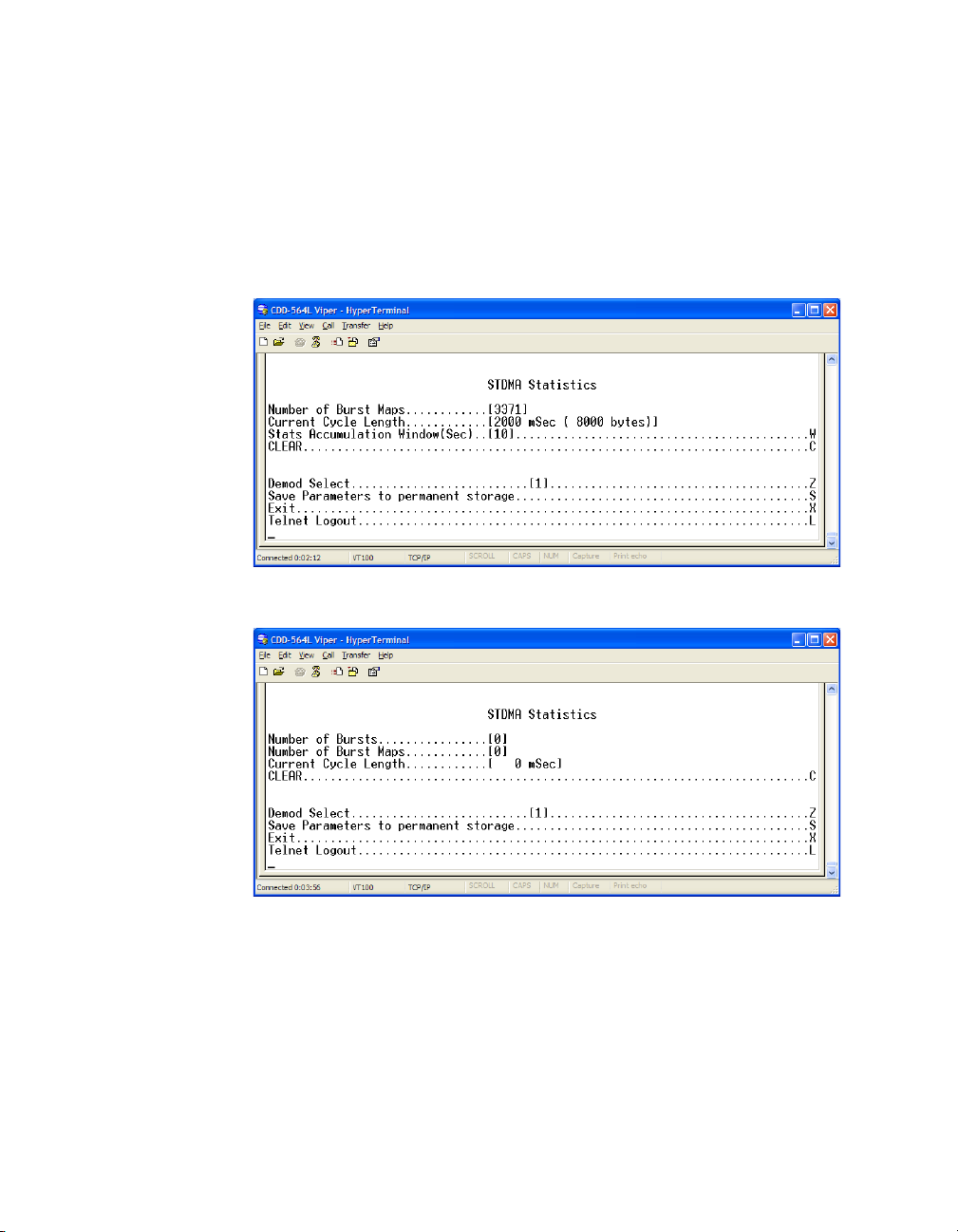
Vi p er sa t C o nf ig ur at io n MN/22137, rev 1
STDMA Statistics
Entering V at the command prompt in the STDMA screen displays the STDMA
Statistics screen as shown in either figure 3-39 (Hub) or figure 3-40 (Remote).
Note that statistics will only be accumulated for a CDD-56X that is configured
as a Hub with No Expansion, since that is the only configuration that provides
STDMA functionality (on Demod 1). Because a Remote unit is SCPC mode
only, the STDMA Statistics screen will display all values as 0.
Figure 3-39
Figure 3-40
STDMA Statistics screen (Hub)
STDMA Statistics screen (Remote)
Stats Accumulation Window
Entering W at the command prompt displays the Stats Accumulation Window
as shown in figure 3-41. The time period, in seconds, for capturing STDMA
statistics can be specified.
3-30 Vipersat CDD-56X Series User Guide
Page 65

MN/22137, rev 1 Vi pe r s a t C o n f ig u r a t i o n
Figure 3-41
Stats Accumulation Window prompt
Clear
The STDMA statistics can be Cleared (reset) by entering a C at the command
prompt in figure 3-39.
Show Hub Statistics
Entering a W at the command prompt in the STDMA screen displays the
current statistics for the target CDD-56X Hub as shown in figure 3-42.
Figure 3-42
Statistics in the received ACK from each Remote are monitored by the Burst
Controller. These statistics report the fill status of the burst data slot for each
Remote. The Burst Controller builds a table of the group and calculates the relative data byte count for each Remote. It then calculates the length of the Data
Slot for each Remote based on the Minimum Slot Length plus a percentage of
the Available Bandwidth. Idle Remotes receive a data slot equal to the Minimum Slot Length.
Show Hub Statistics screen
In figure 3-42, Remote 1 with IP address 10.1.128.1 had activity during the
averaging period. It captured 37.8% of the total slot time and had an average
slot length of 283 ms. Remotes 2, 3, and 4 had 41.5%, 18.1% and 7.6% respectively. The dynamic range of STDMA is a function of the difference between
the Nominal Data Length and the Minimum Data Length parameters. These
Chapter 3 - Using the Command Line Interface (CLI) 3-31
Page 66

Vi p er sa t C o nf ig ur at io n MN/22137, rev 1
NOTE
parameters are operator selectable. The speed with which STDMA reacts to
changes in dynamic load is a function of the Statistics Accumulation Window
parameter and the Cycles per New Burst Map parameter, both of which are also
operator selectable.
The Hub statistics are useful for tuning the Burst Controller. Preamble adjustments, up or down, are made using the missed ACKs statistic; a preamble and/
or guardband that is too short will result in an accumulation of missed ACKs.
The “Cont” column represents continuous—the number of sequential ACKs
missed.
An informative indicator in the Hub Statistics screen is the STDMA status of
the Remotes that appears in the first column to the right of the IP Address list.
The Remote status is displayed in one of three possible modes:
• E – Remote is Enabled and active in the STDMA group; the Hub burst
controller is receiving ACKs from this Remote.
• ER – Remote is Enabled but has been Removed from the STDMA group
due to missed ACKs at the Hub burst controller.
• (Blank) – Remote either has been manually Disabled, such as through the
STDMA Remotes Menu Enable/Disable command, or has been switched
out of STDMA to SCPC mode by the VMS.
STDMA/SCPC Automatic Switching
One of the most powerful features of the Vipersat Network system is the capability to perform Automatic switching between STDMA mode and SCPC mode
based on bandwidth demand. The configuration options that are available to
meet customer-specific requirements are extensive, and include switching based
on Load, Application (Voice and Video RTP), ToS, and QoS.
For additional information, refer to Appendix B, “Automatic Switching”, in this
document.
Note: Care must be taken when configuring the Auto Switching features of the
Vipersat system to ensure that there is no duplication or overlap of
switching functions between Application, ToS, and QoS for a particular
traffic flow. Only one of these switching methods should be utilized for
any one flow requirement.
Automatic Switching for the CDD-56X is an option that is available only when
configured as an STDMA Hub unit (burst controller). Note that Automatic
switching does not apply to either a Hub Expansion unit or a Remote Expansion
unit; these Vipersat working modes operate in dedicated SCPC mode and all
3-32 Vipersat CDD-56X Series User Guide
Page 67

MN/22137, rev 1 Vi pe r s a t C o n f ig u r a t i o n
switching control is performed by the VMS. As is shown in table 2-2, Auto
Switching should be Disabled for these two modes.
The Auto Switching feature must be Enabled (as described in the section
“Feature Configuration” on page 3-5) in order to allow any associated Remote
modems to perform STDMA/SCPC switching. In order for a Remote modem in
the group to be automatically switched between STDMA and SCPC modes, the
Auto Switching feature of that Remote must be Enabled as well.
Selecting Automatic Switching from the Vipersat Configuration menu
shown in figure 3-6 (enter A) for a CDD-56X operating as a network Hub will
display the menu shown in figure 3-43.
Figure 3-43
Automatic Switching screen
The following sections describe the menu items of the STDMA/SCPC Auto
Switching screen shown in figure 3-43.
Auto Switching
The Auto Switching item on the menu shown in figure 3-43 is for information
only and shows the current configuration of the Hub CDD-56X. This feature is
Enabled and Disabled as described in the section “Feature Configuration” on
page 3-5. Auto Switching must be Enabled in order to utilize any of the related
features/commands in this menu.
Note that Auto Switching must be Enabled on a Hub STDMA Controller that is
configured for either Entry Channel or ECMv2 mode.
Chapter 3 - Using the Command Line Interface (CLI) 3-33
Page 68

Vi p er sa t C o nf ig ur at io n MN/22137, rev 1
NOTE
Current WAN Transmit Mode
The Current WAN Transmit Mode item on the menu in figure 3-43 is information only and reflects the current transmit status of a unit. In the case of the
CDD-56X, there is no transmit function (no modulator) and this parameter is
not applicable.
Load Switching
The Load Switching command on the menu in figure 3-43 is a toggle Enabling
and Disabling Load Switching on the target Hub CDD-56X. The system will
detect variations in data rate and can be configured to switch from STDMA to
SCPC based on bandwidth requirements.
The initial switch for a Remote Vipersat terminal from STDMA mode to SCPC
mode is determined by the Hub Burst Controller. Once the Remote is switched
into SCPC, any requests to meet additional switching requirements within
SCPC (Step Up or Step Down) are made by the Remote modem.
Entering a B at the command prompt will toggle this feature On or Off for the
target CDD-56X.
Note: Load switching must be Enabled for any Hub CDD-56X burst controller
that will experience changing load conditions in order for the VMS to
dynamically optimize network performance on these circuits.
Application switching by the VMS (Voice and/or Video) is not affected by
this setting. However, using Load switching for real-time applications is
not recommended.
STDMA Slot Capacity
The STDMA Slot Capacity command, shown in figure 3-43, allows setting the
threshold or level of slot capacity at which the Burst Controller sends a switch
request to the VMS to switch the Remote from STDMA mode to SCPC mode.
Enter U at the command prompt to display the dialog shown in figure 3-44.
Figure 3-44
3-34 Vipersat CDD-56X Series User Guide
STDMA Slot Capacity prompt
Page 69

MN/22137, rev 1 Vi pe r s a t C o n f ig u r a t i o n
A default setting (95%) is provided, but there may be unique network configurations which require modifying the STDMA Slot Capacity value.
STDMA Switch Delay
In order to minimize unnecessary switching from STDMA to SCPC due to transient conditions, such as a temporary spike in network traffic for example, a
switch delay parameter is provided. This setting is used to specify a delay before
a switch occurs.
A default value (10 seconds) is provided, but this value can be changed to
accommodate a unique network configuration or application. To change this
setting, enter W at the command prompt in figure 3-43 to display the screen
shown in figure 3-45.
Figure 3-45
STDMA Switch Delay prompt
Percent Allocation
The Percent Allocation menu item, shown in figure 3-43, allows adding a fixed
percentage to the channel bandwidth request to accommodate additional bandwidth requirements which may occur after a switch is made from STDMA to
SCPC mode.
To change this setting, enter E at the command prompt to display the screen
shown in figure 3-46.
Figure 3-46
Chapter 3 - Using the Command Line Interface (CLI) 3-35
Percent Allocation prompt
Page 70

Vi p er sa t C o nf ig ur at io n MN/22137, rev 1
Typically the default value will be optimum, but if there may be a larger bandwidth requirement after the switch, the percent allocation value can be
increased. In choosing a value for this allocation, future bandwidth requirements for the channel must be balanced against efficient bandwidth utilization.
Keep Alive Timer for Carrier Inhibit
This parameter applies to a Hub unit only. Note that, although this menu item
also appears for a Remote unit, it does not apply to a switched demod unit at a
remote site.
The Keep Alive Timer for Carrier Inhibit parameter provides a fixed setting
that can be specified for the keep alive message sent to the Remotes from the
Hub. This provides an alternate to the burst map which is variable and may
become excessively long in certain applications. An example of this is a burst
map containing a large number (up to 100) of remotes running in ECM mode
where the burst period exceeds the Remote carrier inhibit timer.
When implemented, this parameter is set at either the TDM outbound unit or a
switched demod, not at the STDMA Controller, in order to prevent a problem
should the burst controller be rebooted.
Enter C at the command prompt in the Auto Switching screen to display the
dialog shown in figure 3-47.
Figure 3-47
Keep Alive Timer for Carrier Inhibit prompt
Note that this timer setting should be at least three times faster (shorter in duration) than the timer setting at the Remote(s) to ensure that network links are
maintained.
Hitless Switching Parameters
Unless inherent delays in configuring both ends of a satellite bandwidth link
during dynamic switching are accounted for, transmitted data may be lost
during the transition. The time for a switch command to be sent across the satellite link (~ 250 ms), the command processing time, as well as receiver acquisition time must be considered. The Vipersat Hitless Switching feature provides
3-36 Vipersat CDD-56X Series User Guide
Page 71

MN/22137, rev 1 Vi pe r s a t C o n f ig u r a t i o n
a means to coordinate timing and utilize buffering to eliminate these data
outages.
To access the Hitless Switching screen, enter H from the STDMA/SCPC Auto
Switching screen (see figure 3-43).
Figure 3-48
Hitless Switching screen
This screen will initially display all lock times as -1, indicating that Hitless
Switching is currently disabled. To enable the Hitless Switching feature, enter R
at the command prompt to restore default lock times.
Delay for Mod
This parameter allows the operator to insert additional delay to buffer more data
after modulator transmission is ceased. Enter M to modify this parameter.
Delay for Demod
This parameter allows the operator to insert additional delay to account for the
tuning of the demodulator. Enter D to modify this parameter.
LockTimes
LockTime settings for the four data rates displayed can be adjusted either up or
down, but default settings based on satellite testing should be used as a starting
point. These defaults are stored in each modulator/demodulator unit and are
restored by entering R at the command prompt.
Once restored, the lock time for each data rate can be modified by entering the
corresponding number.
Chapter 3 - Using the Command Line Interface (CLI) 3-37
Page 72

Vi p er sa t C o nf ig ur at io n MN/22137, rev 1
Figure 3-49
Set LockTime prompt
To disable Hitless Switching, enter -1 for all lock times.
Apply Delay Values
To implement any modifications to the Hitless Switching parameters, enter A at
the command prompt to apply these values to the modem.
SOTM Update
This menu item appears for both the Hub unit and the Remote unit. However,
this feature is not applicable to the CDD-56X.
Unit Role
The Unit Role configuration determines whether the target CDD-56X is to
function as a Remote or as a Hub in the Vipersat satellite network. From the
Vipersat Configuration screen (figure 3-6), enter R to display the dialog
shown in figure 3-50.
Figure 3-50
Unit Role prompt
The setting for this parameter, together with the setting for the Expansion Unit,
will determine the role the target CDD-56X will perform in the network and
what type of commands and functions it will receive from the VMS. See
table 2-1 and table 2-2 for a breakdown of network roles and related functions
and features.
3-38 Vipersat CDD-56X Series User Guide
Page 73

MN/22137, rev 1 Vi pe r s a t C o n f ig u r a t i o n
NOTE
Expansion Unit
The Expansion Unit menu item in the Vipersat Configuration screen
(figure 3-6) defines whether the target CDD-56X is to function as an Expansion
unit (all demods configured to operate in SCPC mode) or not. Entering E at the
command prompt will display the dialog shown in figure 3-51.
Figure 3-51
Expansion Unit prompt
The VMS uses this data when monitoring and controlling the network to determine the target CDD-56X’s function. For example, in a Hub configuration that
has STDMA enabled for the first demod, Expansion Unit should be set to No.
When configured as an Expansion unit, either as a Hub (switched) or as a
Remote (mesh), the CDD-56X is set up so that all demods are in SCPC mode
and available as resources for dedicated communications with the other end of
the satellite link.
For a Remote configuration, this parameter must be set to Yes. For a Hub
configuration, this parameter can be set to either No or Yes. Refer to table 2-1
and table 2-2 for a breakdown of network roles and related functions and
features.
Note: Setting Vipersat STDMA to Disabled alone will not force the demods into
an SCPC role—the Expansion Unit parameter must be set to Yes for this
function. Likewise, Expansion Unit must be set to No together with
STDMA Enabled for proper STDMA function.
Network ID
The Network ID that is assigned to the unit defines to what network the target
CDD-56X will belong. All units used in a network will have the same Network
ID. Enter B at the command prompt in the Vipersat Configuration screen
(figure 3-6) to display the dialog shown in figure 3-52.
Chapter 3 - Using the Command Line Interface (CLI) 3-39
Page 74

Vi p er sa t C o nf ig ur at io n MN/22137, rev 1
Figure 3-52
Network ID prompt
The Network ID is used by the VMS to identify units that are common to a
network and allows the VMS to manage multiple networks, each with its own
unique Network ID number.
Unit Name
The Unit Name command in the Vipersat Configuration screen (figure 3-6) is
used to assign a name to the target CDD-56X. Enter N at the command prompt
to display the dialog shown in figure 3-53 . Any name, up to 16 characters, can
be entered for the unit.
Figure 3-53
This name is displayed by the VMS and identifies the unit in Network Manager,
the graphical network display.
Unit Name prompt
Receive Multicast Address
The Receive Multicast Address is the multitcast IP address assigned to all
CDD-56X units in the Vipersat network that are managed by the VMS server.
This address must match the VMS Transmit Multicast Address.
When the CDD-56X receives a multicast from the VMS server, it receives
maintenance and control packets, including the server’s IP address. The
3-40 Vipersat CDD-56X Series User Guide
Page 75

MN/22137, rev 1 Vi pe r s a t C o n f ig u r a t i o n
NOTE
CDD-56X responds to the VMS server with a unicast containing its current
configuration data, including the CDD-56X’s IP address. When the VMS
receives the unicast response, it registers the CDD-56X on the network.
Enter V at the command prompt in the Vipersat Configuration screen
(figure 3-6) to display the dialog shown in figure 3-54. Enter the Receive Multicast Address as assigned by the network operator/administrator.
Figure 3-54
Receive Multicast IP Address prompt
Managing IP Address
The Managing IP Address command in the Vipersat Configuration screen
(figure 3-6) allows the IP address for the server running VMS to be entered.
Enter I at the command prompt to display the dialog shown in figure 3-55.
Figure 3-55
The Managing IP Address of the VMS is sent out with the multicast to all of the
Vipersat units and will be automatically updated during the registration process.
The CDD-56X sends a unicast registration request to the managing address
every 60 seconds when requesting initial registration on the VMS network.
Later the CDD-56X uses this address to send switch requests, network health
status messages, etc. to the managing VMS server.
Managing IP Address prompt
Note: The managing address will be set automatically if the Receive Multicast
Address is configured correctly and the unit is receiving the announcement multicast message. However, the unit WILL NOT send its registration request message until this address is set.
Chapter 3 - Using the Command Line Interface (CLI) 3-41
Page 76

Vi p er sa t C o nf ig ur at io n MN/22137, rev 1
NOTE
Once the unit is registered, the I command is removed from the Vipersat
Configuration menu.
This managing address is automatically updated on a periodic basis for units
that are newly enabled, incorrectly set, or following VMS changeovers (redundancy switching). The status of the registration process is displayed for this
parameter as follows:
• NOT-DEFINED — unit has booted up, but is unaware of the managing
address.
• No STDMA Xmit Grant — operator has entered managing address, but
unit (Remote) is not currently receiving burst maps.
• Sending Registration (n) — unit is receiving burst maps and the number
of registration attempts (n) is displayed.
• Registered — unit is registered with the VMS. For VMS v3.6.0 and later,
the VMS version number is also displayed (as shown in figure 3-6).
Management Security
Management Security is an optional Vipersat feature that provides encryption
on all VMS management messages passed between the VMS and the network
modems. When enabled, the VMS and all of the network modems must utilize a
common Encryption Key that is manually set on each. The key can be entered
either as an ASCII hex string of exactly 64 characters, or as a passphrase
consisting of 5 to 63 characters.
For modems that operate with Management Security, Enable this feature and
enter the Encryption Key that has been defined for the network.
Note: VMS version 3.7.1 or greater is required for Management Security.
Caution: During the process of network-wide key distribution and enabling of
encryption, communications may be lost as the STDMA control
messages will be unreadable until all modems in the network are
configured.
It is recommended that each of the Remote units be configured for
Management Security first, and then the Hub units be configured.
This method will reduce the need for on-site personnel during feature
implementation.
If the FAST feature key for Management Security has been purchased for the
target modem, then it will appear as a menu item on the Vipersat Configuration
screen (figure 3-6).
3-42 Vipersat CDD-56X Series User Guide
Page 77

MN/22137, rev 1 Vi pe r s a t C o n f ig u r a t i o n
Enter K at the command prompt to configure this feature, as shown in
figure 3-56, below.
Figure 3-56
Vipersat Management Security screen
Enter M at the command prompt to toggle between Enabled/Disabled. Note that
the feature must be set to Enabled in order to configure the encryption key.
Enter K at the command prompt and Enter the required key (figure 3-57).
(Following entry, the characters will be temporarily displayed in the menu for
reference pruposes.)
Figure 3-57
Encryption Key Entry prompt
Enter V at the command prompt and re-enter the same key to Verify it.
(Following entry, the characters will be temporarily displayed in the menu for
reference purposes.)
Enter G at the command prompt to execute the verfication process and Gener-
ate the hex key.
The Future Key menu item will display Valid to indicate successful verification
of the key and that it is ready for activation.
Enter A at the command prompt to Activate the key for current use.
The Current Key menu item will display Valid to indicate successful activation.
Chapter 3 - Using the Command Line Interface (CLI) 3-43
Page 78

Vi p er sa t C o nf ig ur at io n MN/22137, rev 1
Primary Heart Beat
This menu item appears for the Hub terminal only.
The Primary Heart Beat feature is a redundancy heart beat message for
primary Hub units that provides the option for a periodic communications check
message to be sent from the Hub modem to the VMS for backup recovery in
N:M redundancy (protected) configurations. The message interval is hard-coded
in the demod.
Enter P at the command prompt in the Vipersat Configuration screen
(figure 3-6) to toggle this feature between Enabled and Disabled.
Home State Revert
This menu item appears for the Remote terminal only.
The Home State Revert feature allows automatic resource recovery to be
performed on SCPC connections when a communications failure occurs
between the VMS and a Remote, such as a rain fade condition, a Remote unit
power down, or a hardware failure. The period of time (in minutes) for a failure
is configured in the VMS for each Remote in the network. Should communications be lost for more than the specified time period, the Remote will automatically revert to its Home State settings and the VMS will remove all allocated
resources (bandwidth, demod(s)), freeing them for use by any other Remote in
the Vipersat network.
Because this feature is configured in the VMS, the status (Disabled, or the time
period in minutes) appears as an information-only display in the Vipersat
Configuration menu (figure 3-6).
Dynamic Power Control Configuration
Dynamic Power Control (DPC) is a Vipersat feature that acts to regulate the
transmit power of the Vipersat satellite modem, such that the specified receive
signal level (E
driven by the receiver demod, which notifies the transmitting modem of the
current E
Refer to Appendix C, “Dynamic Power Control”, in this document for additional information on the DPC feature.
The Dynamic Power Control Configuration screen (enter C in the Vipersat
Configuration menu) allows for setting the parameters for the CDD-56X power
3-44 Vipersat CDD-56X Series User Guide
b/No
) is met for the receiving Vipersat units in the group. DPC is
b/No
value.
Page 79

MN/22137, rev 1 Vi pe r s a t C o n f ig u r a t i o n
levels. The information and commands in the menu will vary depending on the
function the target CDD-56X performs in the network. The screen shown in
figure 3-58 is from a unit serving as a Hub with STDMA (burst controller).
Note, however, that the only parameter settings that apply to the CDD-56X are
DPC Enabled, Speed Up EbNo, and Target DPC Address. Because all of the
remaining settings shown in this screen are redundant to those configured in the
satellite modem (CDM-570), they do not apply to the CDD-56X and can be
disregarded.
For comparison, the DPC Configuration screen for a unit operating as a Hub or
Remote with Expansion (SCPC mode) is shown in figure 3-59. Note that only
the applicable settings appear in this screen.
Figure 3-58
Figure 3-59
Tip: The DPC feature will not function unless the Outbound IP address is
defined in the STDMA screen for the Hub BC modem.
Chapter 3 - Using the Command Line Interface (CLI) 3-45
DPC Configuration screen (Hub, STDMA)
DPC Configuration screen (Hub/Remote, SCPC)
Page 80

Vi p er sa t C o nf ig ur at io n MN/22137, rev 1
DPC Enabled
The DPC Enabled command (enter E) is a toggle that allows the Dynamic
Power Control feature to be either Enabled or Disabled. The CDD-56X is
shipped with the DPC Enabled menu item turned off (Disabled) to allow
entrance link levels calibration during terminal setup.
Speed Up EbNo
Normally, the DPC message is sent every 60 seconds from each terminal in the
network. If the current E
EbNo set value, the corresponding terminal increases its message send rate to
every 15 seconds until the current value becomes greater than the set value. This
provides a loop speed up to rapidly regain link quality.
Enter Q at the command prompt in the DPC Configuration screen to access the
Speed Up EbNo dialog shown in figure 3-60. The default value for this parameter is 5 dB.
value of the terminal drops below the Speed Up
b/No
Figure 3-60
Speed Up EbNo prompt
Target DPC Address
The Target DPC Address identifies the modem that is transmitting to this
CDD-56X Demod, and will be receiving the DPC messages that provide the
current E
modem that is supplying the TDM outbound carrier.
For STDMA Remotes, the Outbound IP address is sent out via the Burst Map,
and the DPC Target for these Remotes is automatically mapped to that address.
The Target DPC Address command is used only for units that are Out-of-Band
and will be utilizing the DPC feature. For In-Band units, the target addresses are
handled automatically by the VMS.
To manually configure the target address for an Out-of-Band unit, enter the
number corresponding to the appropriate Demod (1, 2, 3, or 4) at the command
prompt to display the Target DPC Address dialog shown in figure 3-61.
3-46 Vipersat CDD-56X Series User Guide
value for this Demod. Typically, all Remotes will specify the Hub
b/No
Page 81

MN/22137, rev 1 Vi pe r s a t C o n f ig u r a t i o n
Figure 3-61
Target DPC Address prompt
The STDMA Burst Controller (Demod 1 on a CDD-56X configured as Hub
with No Expansion) is not permitted to specify a DPC Target because the
demodulator is receiving multiple bursts very rapidly from all Remotes in the
group and is unable to utilize DPC to control the transmit power of the Remote
modems. However, the transmit power of the Burst Controller adjusts to meet
the target E
status and E
values for the Remotes in the group. These Remotes and their
b/No
values are displayed in the Vipersat Summary screen, DPC
b/No
details (see “Vipersat Summary” on page 3-51).
Set Home State Parameters
A CDD-56X’s Home State consists of those parameters which provide a
known RF configuration that the CDD-56X will return to, either as the result of
a command by the VMS, or as it comes back on line from a reset or a power
cycle.
Enter H at the command prompt in the Vipersat Configuration screen to
display the Home State Configuration screen shown in figure 3-62.
A CDD-56X’s Home State settings are typically selected so that it goes to a
configuration which is optimum for its function in the network. These parameters are configured on an individual, per demod basis.
Note that each of these Receive parameters are the same as found in the Rx
Configuration screen that is in the Satellite Demod Configuration menu.
Chapter 3 - Using the Command Line Interface (CLI) 3-47
Page 82
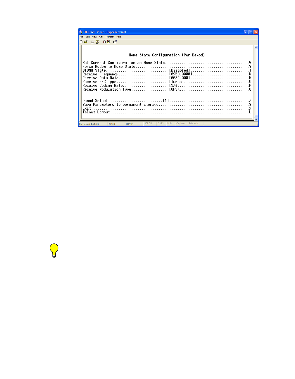
Vi p er sa t C o nf ig ur at io n MN/22137, rev 1
Figure 3-62
Home State Configuration screen
Set Current Configuration as Home State
This command sets the selected Demod’s current configuration as its Home
State settings. Assuming the Demod has been properly configured using the
Satellite Demodulator Configuration menu (Rx parameters) and the Feature
Configuration menu (Vipersat STDMA setting), these parameter values will be
copied into the Home State configuration. Rather than entering each of these
values individually, this command can be used as a shortcut for establishing the
Home State settings.
Enter W at the command prompt in the Home State Configuration screen to
execute this command. Once saved, the modem will be configured with the
Home State settings at boot time and when manually reset with the Force
Modem to Home State command.
Tip: This command is useful when a CDD-56X’s initial set up is completed and
the unit is functioning as desired in a network.
Force Modem to Home State
If at any time it is desired to have a CDD-56X return to its Home State, this
command (enter Y) can be executed. A warning message is displayed as shown
in figure 3-63, requiring the command to be confirmed before it is executed.
3-48 Vipersat CDD-56X Series User Guide
Page 83

MN/22137, rev 1 Vi pe r s a t C o n f ig u r a t i o n
NOTE
Figure 3-63
Force Modem to Home State warning
This command will force the selected Demod to its Home State configuration,
replacing its current configuration.
STDMA State
This command (enter T) toggles the setting of STDMA in the target
CDD-56X’s Home State between Enabled and Disabled. This is the same
feature that is set from the Feature Configuration menu screen shown in
figure 3-4. Setting the STDMA State to Enabled is only applicable for a
CDD-56X that is configured as a Hub burst controller.
Note: Only one demod can be set with STDMA enabled. Vipersat recommends
that Demod 1 be utilized for applications calling for STDMA.
Receive Frequency
Enter M to use the dialog shown in figure 3-64 to set the Receive Frequency
for the selected Demod’s Home State.
Figure 3-64
Receive Frequency prompt
Note that this screen dialog example displays the frequency range for a CDD562L/564L L-Band Demodulator/Router. For a CDD-564, the range displayed
will be either 50 to 90 MHz or 100 to 180 MHz.
Receive Data Rate
Enter N to use the dialog shown in figure 3-65 to set the Receive Data Rate for
the selected Demod’s Home State.
Chapter 3 - Using the Command Line Interface (CLI) 3-49
Page 84

Vi p er sa t C o nf ig ur at io n MN/22137, rev 1
Figure 3-65
Receive Data Rate prompt
Note that the valid range for this parameter will vary depending on the Demodulation Type, Coding Rate, and FAST feature Data Rate.
Receive FEC Type
Enter O to use the dialog shown in figure 3-66 to set the Receive FEC Type for
the selected Demod’s Home State. Turbo must be selected when operating in
Vipersat mode.
Figure 3-66
Receive FEC Type prompt
Receive Coding Rate
Enter P to use the dialog shown in figure 3-67 to set the Receive Coding Rate
for the selected Demod’s Home State.
Figure 3-67
3-50 Vipersat CDD-56X Series User Guide
Receive Coding Rate prompt
Page 85

MN/22137, rev 1 Vi pe r s a t C o n f ig u r a t i o n
Note that Coding Rate 6 (1/1) is not a valid selection when operating in Vipersat
mode with Turbo Product Coding.
Receive Modulation Type
Enter Q to use the dialog shown in figure 3-68 to set the Receive Modulation
Type for the selected Demod’s Home State.
Figure 3-68
Receive Modulation Type prompt
Vipersat Summary
The Vipersat Summary screen can be viewed by entering D at the command
prompt in the Vipersat Configuration screen (figure 3-6).
Figure 3-69
Chapter 3 - Using the Command Line Interface (CLI) 3-51
Vipersat Summary screen
Page 86

Vi p er sa t C o nf ig ur at io n MN/22137, rev 1
The Node ID number that appears in this screen verifies that the unit is registered with the VMS and is active in the network. This number is automatically
assigned by the VMS.
Note that the four Demods of the CDD-56X are designated as 0 through 3 on
this screen. The IF values represent the Intermediate Frequency (Hz) that this
unit is currently using. The AF values represent Adjusted Frequency (Hz), a
translation of the IF that is used by the VMS for internal tracking of switching
commands.
The DPC target entries are the IP addresses of the modulators that are to
receive the Dynamic Power Control messages from the Demods for this unit.
The Primary Heart Beat Interval represents the time period between the
communication check message that is sent from the primary Hub CDD-56X to
the VMS in an N:M redundancy configuration. This interval is specified in the
VMS.
Data for the Current Switch Cache reflects either the Home Satae information
immediately after the unit boots, or the last switch command from the VMS (the
last command sent to the base modem).
DPC details provide the status and E
values for active Remotes in the
b/No
group.
Vipersat Migration
The Vipersat Migration command is used to set the compatibility mode for the
Hub Burst Controller when conducting a firmware upgrade on the associated
Remotes. Although this command appears in the menu for both the Hub modem
and the Remote modem, it only applies to STDMA Controllers and TDM
Outbound modems at the Hub.
Enter M at the command prompt in the Vipersat Configuration screen to
display the Vipersat Migration dialog shown in figure 3-70.
Refer to the specific upgrade procedure that is to be implemented for instructions on whether/how to utilize this feature.
3-52 Vipersat CDD-56X Series User Guide
Page 87

MN/22137, rev 1 Vi pe r s a t C o n f ig u r a t i o n
Figure 3-70
Vipersat Migration prompt
UDP Port Base Address
Should a particular network application require a specific UDP port base
address be used, the default address can be changed by entering U at the
command prompt in the Vipersat Configuration screen (figure 3-6).
Figure 3-71
Caution: This command affects all communications for the VMS and STDMA.
If the base address is changed, it must be changed in the VMS as
well as in all modems in all networks controlled by the VMS. The base
address must also be changed when using VLOAD with this network.
UDP Port Base Address prompt
Alerts
The Alerts menu item in the Vipersat Configuration screen is for information
only and serves to display alert messages to the operator.
Chapter 3 - Using the Command Line Interface (CLI) 3-53
Page 88

Vi p er sa t C o nf ig ur at io n MN/22137, rev 1
• Example: “Critical error: should not be in map”
This alert typically occurs when there are multiple STDMA burst
controllers at the Hub incorrectly configured with the same Group ID, thus
causing Remotes to appear in more than one bursmap. A Remote may
already be switched out into dSCPC mode, yet continue to appear in a
burstmap that is received from another controller.
3-54 Vipersat CDD-56X Series User Guide
Page 89

NETWORK ADDRESSING
Introduction
This Appendix is an overview of network addressing and how it applies to
configuring the CDD-562L/564/564L for use in Vipersat Networks. The
subjects covered are:
A
PPENDIX
• OSI Model
• Binary Math
• IP Addressing
• Network Address Translation
• Subnets
• Network Segments
• Default Gateways
• MAC Addresses
Appendix A - Network Addressing A-1
Page 90

Th e O S I R e f e re nc e M o de l MN/22137, rev 1
The OSI Reference Model
OSI is an acronym for Open Systems Interconnection. This is a network model
created by ISO (the International Standardization Organization.) The OSI model
is the basic standard which forms the basis for all networking protocols.
Figure A-1
The OSI model defines the building blocks used to construct a working network
protocol as shown in Figure A-1. The blocks on the right show the individual
layers which make up the OSI model and the blocks on the left show the layer’s
functional grouping.
Each layer, as defined by the OSI model, is only aware of the layers directly
above and below it.
The Seven OSI Protocol Layers
Layers 1 – 3
Layer 1 / Physical – Layer 1 defines the physical means by which actual bits
are sent and received. This layer, for example, is where connectors, cable
lengths, and signaling specifications are defined.
Layer 2 / Data Link – Layer 2 consist of two sub-layers:
• Logical Link Control (LLC) – The LLC packages bytes received from the
MAC into a format readable by the Network Layer above it.
• Media Access Control (MAC) – The MAC is concerned with obtaining
access to the network at an appropriate time; i.e., when no other machines
are communicating or when permission has been granted.
A-2 Vipersat CDD-56X Series User Guide
Page 91

MN/22137, rev 1 Th e O S I R e f e r e n c e M o de l
Together, these two sub-layer protocols are responsible for moving packets on
and off the network.
Layer 3 / Network Layer – Layer 3 is responsible for routing packets through
multiple networks. The Layer 3 protocol operates without regard to the underlying protocols in use. For example, routers operate at Layer 3.
Appendix A - Network Addressing A-3
Page 92

Bi n ar y M a th MN/22137, rev 1
128 64 32 16 8 4 2 1
1
101 100 01 = 165
11 10 0 0 0 0 = 194
1111 11 11=255
128
32
4
1
_____
165
Binary Math
Network devices communicate using BITS, where a bit is a single digit represented by a 1 or a 0, or by using BYTEs, where a byte is made up of eight bits in
any combination of 1’s or 0’s. A byte is also referred to as an octet.
Figure A-2
Bits and Bytes
An octet can be converted to or from binary using the technique shown in the
decimal conversion chart in Figure A-3. The conversion chart also shows the
decimal equivalent of the binary number.
Figure A-3
Binary to Decimal Conversion
Bits containing a 1 in Figure A-3 determine which decimal values should be
added. These decimal values, when added together, determine the decimal
equivalent for the binary number.
This is an example of changing a number expressed in binary (base 2) to its
decimal equivalent (base 10). The numeric value is the same, you have only
A-4 Vipersat CDD-56X Series User Guide
Page 93

MN/22137, rev 1 Bi n a r y M a t h
changed the numbering base (radix.) All digital processes are done in binary.
The conversion to decimal is done whenever binary values need to be read or
entered by humans as their decimal equivalents.
Appendix A - Network Addressing A-5
Page 94

IP Ad dr es si ng MN/22137, rev 1
IP Addressing
An IP (Internet Protocol) address is a unique set of numbers assigned to a device
on a network to uniquely identify that device (by its IP address).
An IP address is a unique number composed of four octets, with each octet
separated by a dot. This notation style is called dotted decimal notation.
Each IP address can be broken down into two parts, as shown in the example
below:
Example:
128.121.188.201
The first two octets are the network ID:
The second two octets are the host ID:
128.121
188.201
• Network ID - In this example, the 128.121 portion of the IP address
defines the network that a host belongs to, and is equivalent to a street
name in a mailing address.
• Host ID - The 188.201 portion of the IP address specifies a unique number
assigned to the host on the network, and is equivalent to a house number in
a mailing address.
IP Address Classes
IP addresses are assigned to classes according the schedule shown in
Figure A-4. IP address classes are assigned as follows:
Class A
• 1.x.x.x to 126.x.x.x (0 and 127 are reserved)
• 126 Class As exist
• Can have 16,777,214 hosts on each Class A
• 8-bit network number
• 24-bit node number
Class B
• 128.0.x.x to 191.254.x.x
• 16,384 Class Bs exist
• Can have 65,354 hosts on each Class B
A-6 Vipersat CDD-56X Series User Guide
Page 95

MN/22137, rev 1 IP A d d re s s i ng
CLASS A
CLASS B
CLASS C
2,097,152
16,384
126
Networks
Available
192-223.x.y.z
128-191.x.y.z
1-126.x.y.z
1
st
Octet
Decimal Range
254110 Class C
65,53410Class B
16,777,2140Class A
Hosts
Available
HighOrder-Bits
Address
Class
2,097,152
16,384
126
Networks
Available
192-223.x.y.z
128-191.x.y.z
1-126.x.y.z
1
st
Octet
Decimal Range
254110 Class C
65,53410Class B
16,777,2140Class A
Hosts
Available
HighOrder-Bits
Address
Class
• 16-bit network number
• 16-bit node number
Figure A-4
IP Address Classes A, B, C
Class C
• 192.0.1.x to 223.255.254.x
• 2,097,152 Class Cs exist
• Can have 254 hosts on each Class C
• 24-bit network number
Class D
• 224.0.0.0 to 239.255.255.255
• 8-bit node number
• Reserved for Multicast (messages sent to many hosts).
Appendix A - Network Addressing A-7
Page 96

IP Ad dr es si ng MN/22137, rev 1
Ethernet
Host 1
Host 2
NAT Router
Internet
192.168.0.2
192.168.0.3
192.168.0.1 Public IP
Class E
• 240.0.0.0 to 255.255.255.255
• Reserved for experimental use and limited broadcast
Private Network IP Addresses
RFC 1918 defines blocks of addresses for use on private networks:
• 10.0.0.0 – 10.255.255.255
• 172.16.0.0 – 172.31.255.255
• 192.168.0.0 – 192.168.255.255
Network Address Translation (NAT)
Private networks can only connect to the public Internet by using a Network
Address Translation (NAT) device (a router, for example) or a proxy server
which has been assigned a public IP address. These network devices use a
public IP address to request information from the Internet on behalf of the
private IP addressed devices on the associated private network.
Figure A-5
NAT Router Example
This use of private addresses helps to conserve public IP addresses.
Subnets
Subnets can be defined as the further segmentation of the InterNIC assigned
Network ID IP address. The amount and type of subnetting performed by the
organization is determined by the network layout.
A-8 Vipersat CDD-56X Series User Guide
Page 97

MN/22137, rev 1 IP A d d re s s i ng
11111111.11111111.11111111.00000000255.255.255.0Class C
11111111.11111111.00000000.00000000255.255.0.0Class B
11111111.00000000.00000000.00000000255.0.0.0Class A
Mask Binary ValueMask Decimal ValueAddress Class
11111111.11111111.11111111.00000000255.255.255.0Class C
11111111.11111111.00000000.00000000255.255.0.0Class B
11111111.00000000.00000000.00000000255.0.0.0Class A
Mask Binary ValueMask Decimal ValueAddress Class
CLASS A
CLASS B
CLASS C
In the process of subnetting, bits are borrowed from the host ID portion of an IP
address and are then given to the network ID. Then a “Subnet Mask” gets
assigned to the host along with the IP address.
Subnetting is required if the network is segmented.
Subnet Mask
The Subnet Mask is used by the host to determine if a destination IP address is
on the local or on a remote network segment. The table in Figure A-6 shows the
default subnet mask used for each class of IP address.
Figure A-6
Default Subnet Masks for IP Classes
The IP address and subnet mask work with each other to identify a network
element or device. The subnet mask, like an IP address, contains 4 octets separated by a dot (.) and looks similar to an IP address.
The subnet mask determines what bits in the IP address are being used to determine the network ID by using the Boolean math operator and in a process
called anding. Anding compares each bit value in the IP address with the bit
value in the subnet mask. The result of the anding process determines which
subnet the IP address is on. The Boolean and operator works as follows:
0 and 0 = 0
1 and 0 = 0
1 and 1 = 1
The table shown in Figure A-7 shows the anding of two binary values and the
corresponding decimal equivalents for each of the values.
Appendix A - Network Addressing A-9
Page 98

IP Ad dr es si ng MN/22137, rev 1
ANDing Result
Subnet Mask
IP Address
11000000.10101000.00000010.00000000192.168.2.0
11111111.11111111.11111111.00000000255.255.255.0
11000000.10101000.00000010.01000010192.168.2.66
Binary Values
Dotted Decimal
Address
ANDing Result
Subnet Mask
IP Address
11000000.10101000.00000010.00000000192.168.2.0
11111111.11111111.11111111.00000000255.255.255.0
11000000.10101000.00000010.01000010192.168.2.66
Binary Values
Dotted Decimal
Address
Figure A-7
ANDing an IP address and a subnet mask
A calculator, available from SolarWinds, performs these IP and subnet mask
calculations and can be found at:
http://www.solarwinds.com/products/freetools/index.aspx
Network Segments
A “Network Segment” is a portion of a network that is bordered by two router
interfaces as shown in Figure A-8.
A-10 Vipersat CDD-56X Series User Guide
Each network segment must either be on a different network or a different
subnet. For example, if you have a single IP address available, you can change
the default mask from 255.255.255.0 to 255.255.255.192. The resulting calculation yields four subnets:
• 192.168.100.0
• 192.168.100.64
• 192.168.100.128
• 192.168.100.192
Figure A-8
Network Segments
Page 99

MN/22137, rev 1 IP A d d re s s i ng
Each of the four subnets can, in turn, support 64 members.
The example subnet used above yielded 4 subnets, but you can use a different
mask to meet the specific requirements of your network.
Default Gateways
A default gateway is a network device, usually a router, that is responsible for
routing data packets out of the local network segment.
The address of the gateway is entered into the devices on the local network,
providing them with a location to send data that is destined for another segment.
Figure A-9
Router as Default Gateway
MAC Addresses
A MAC address is a physical hardware address that gets assigned to the interface of a networking device. This address is typically created and burned into a
device’s ROM during the manufacturing process. MAC addresses are unique to
the device and are not typically user-assignable.
The MAC address is used for Layer 2 (Data Link) communications between
networking devices, and consists of 12 alpha-numeric characters as shown in
the example below:
Example: 00-3f-bf-00-01-45
Appendix A - Network Addressing A-11
Page 100

IP Ad dr es si ng MN/22137, rev 1
• The first six characters are issued to the organization.
• The second six characters are assigned to the hardware interface by
manufacturing.
Figure A-10
Network Node MAC Addresses
A-12 Vipersat CDD-56X Series User Guide
 Loading...