

Page 1
CDD-562AL/564A/L
Multi-Channel Demodulator
Installation and Operation Manual
CDD-564A 70/140 MHz Satellite Quad Demodulator
CDD-564AL L-Band Satellite Quad Demo dula tor
CDD-562AL L-Band Satellite Dual De modul ato r
For Firmware Version 1.3.1 or higher
IMPORTANT NOTE: The information contained in this document supersedes all previously published
information regarding these products. Product specifications are subject to change without prior notice.
Part Number MN-CDD562AL564AL Revision 0
Page 2

Page 3
ErrataA
Errata A for MN-CDD562AL564AL Rev 0
Comtech EF Data Documentation Update
Subject:
Errata Part
Number:
PLM CO
Number:
Comments:
Add Default IP Address in Chapters 9 and 10
ER-CDD562564AL-EA0 Rev - (Errata documents are not revised)
C-0034791
Thesechangeswillbeincorporatedintothenextmanualrevision:
1. INCHAPTER9.TELNETANDCLIOPERATION,SECT.9.2.2.2.1(PAGE9‐18),ADDDEFAULT
IPADDRESSASFOLLOWS:
2. INCHAPTER10.HTTPWEBINTERFACE,SECT.10.1.1(PAGE10‐1),ADDDEFAULTIP
ADDRESSASFOLLOWS:
ER-CDD562564AL-EA0 Rev - PLM C-0034791
Page 4

ErrataA
BLANK PAGE
ER-CDD562564AL-EA0 Rev - PLM C-0034791
Page 5
Errata B for MN-CDD562AL564L Rev 0
Comtech EF Data Documentation Update
Subject:
Update page 1-13, change 3xDES Data Encryption Installation Method to Available as
EN model
Errata Part Number:
PLM CO Number:
Comments:
ER-CDD562564L-EB0 (Errata documents are not revised)
C-0035153
See attached page(s). The new information will be included in the next released
revision of the manual.
ER-CDD562564L-EB0 Rev -
Page 6
ER-CDD562564L-EB0 Rev -
Page 7
CDD-562AL/564A/L
Multi-Channel Demodulator
Installation and Operation Manual
CDD-564A 70/140 MHz Satellite Quad Demodulator
CDD-564AL L-Band Satellite Quad Demo dula tor
CDD-562AL L-Band Satellite Dual De modul ato r
For Firmware Version 1.3.1 or higher
Part Number MN-CDD562AL564AL
Revision 0
Copyright © 2015 Comtech EF Data. All rights reserved. Printed in the US A.
Comtech EF Data, 2114 West 7th Street, Tempe, Arizona 85281 USA, 480.333.2200, FA X: 480.333.2161
Page 8

Blank Page
ii
Page 9

TABLE OF CONTENTS
PREFACE ................................................................................................................................... XI
About this Manual ..................................................................................................................................... xi
Warnings, Cautions, and Notes .................................................................................................................................. xi
Patents and Trademarks.............................................................................................................................................. xi
Electrical Safety and Compliance .............................................................................................................................. xi
Electrical Installation ................................................................................................................................................ xii
Fuses xii
Grounding.................................................................................................................................................................. xii
European Union Radio Equipment and Te lecommunicati ons Termina l Equipment (R&TTE) D irective
(1999/5/EC) and EN 301 489-1 .............................................................................................................................. xiii
EMC (Electromagnetic Compatibility) .................................................................................................. xiii
European Union RoHS Directive (2002/95/EC) .................................................................................... xiv
European Union Telecommunications Te rminal Equipment Directive (91/26 3/EEC) ...................................... xiv
CE Mark xiv
Federal Communications Commission .................................................................................................................... xv
Product Support ........................................................................................................................................ xv
Comtech EF Data Headquarters ............................................................................................................. xv
Warranty Policy ....................................................................................................................................... xvi
Limitations of Warranty .......................................................................................................................................... xvi
Exclusive Remedies ................................................................................................................................................. xvi
CHAPTER 1. INTRODUCTION ............................................................................................. 1–1
1.1 Overview ...................................................................................................................................... 1–1
1.1.1 CDD-56xA/L Features ......................................................................................................................... 1–2
1.2 Functional Description ............................................................................................................... 1–2
1.3 Features ........................................................................................................................................ 1–5
1.3.1 Physical Description ............................................................................................................................. 1–5
1.3.2 Major Assemblies ................................................................................................................................. 1–5
1.3.3 Interoperability/Compatibility .............................................................................................................. 1–5
1.3.4 Dimensional Envelopes ........................................................................................................................ 1–6
1.3.5 Physical Features ................................................................................................................................... 1–9
1.3.6 Data Interfaces ..................................................................................................................................... 1–12
1.3.7 Updating Demodulator Firmware ...................................................................................................... 1–12
1.3.8 Fully Accessible System Topology (FAST) ..................................................................................... 1–13
1.4 Summary of Specifications ....................................................................................................... 1–14
1.4.1 Demodulator ........................................................................................................................................ 1–14
1.4.2 Data Rate Ranges ................................................................................................................................ 1–18
iii
Page 10

CDD-562AL/564A/L Multi-Channel Dem odulator Revision 0
Table of Contents MN-CDD562AL564AL
1.4.3 Low Noise Block Converter (LNB) Support (CDD-564AL only) ................................................. 1–19
1.4.4 Environmental and Physical ............................................................................................................... 1–19
1.4.5 Network Protocols .............................................................................................................................. 1–20
CHAPTER 2. INSTALLATION AND STARTUP .................................................................... 2–1
2.1 Unpacking and Inspecting the Shipment .................................................................................. 2–1
2.2 Installing the CDD-56xA/L into a rack ..................................................................................... 2–2
2.2.1 Installing the Optional Rear Support Brackets Kit ............................................................................. 2–4
2.3 Initial Configuration ................................................................................................................... 2–5
2.4 Connecting External Cables ....................................................................................................... 2–5
CHAPTER 3. REAR PANEL CONNECTOR PINOUTS ........................................................ 3–1
3.1 CDD-56xA/L Rear Panels Overview ......................................................................................... 3–1
3.2 CDD-56xA/L Cable Connections ............................................................................................... 3–2
3.2.1 Rx IF Connections ................................................................................................................................ 3–3
3.2.2 Terrestrial Data Connections – 10/100 Ethernet (RJ-45) ................................................................... 3–4
3.2.3 Utility Connections ............................................................................................................................... 3–5
3.3 CDD-56xA/L Ground and Power Connections ........................................................................ 3–6
3.3.1 Chassis Ground Interface ..................................................................................................................... 3–6
3.3.2 100V/240V Alternating Current (AC) Power Interface (Standard) .................................................. 3–7
3.3.3 48V Direct Current (DC) Power Interface (Optional) ........................................................................ 3–9
CHAPTER 4. IP MODULE ETHERNET INTERFACE ........................................................... 4–1
4.1 Introduction ................................................................................................................................. 4–1
4.1.1 Standard Features .................................................................................................................................. 4–1
4.1.2 10/100 BaseT Ethernet Interfaces ........................................................................................................ 4–2
4.1.3 Powerful Network Management .......................................................................................................... 4–2
4.1.4 Remote Firmware Update via FTP ...................................................................................................... 4–2
4.1.5 Configuration Backup and Restore vi a FTP ....................................................................................... 4–2
4.1.6 Event Logging to Capture All Demodulator Activity ........................................................................ 4–3
4.1.7 Detailed Statistics of IP Traffic ............................................................................................................ 4–3
4.1.8 IGMP Support for Multicast ................................................................................................................ 4–3
4.1.9 Static IP Routing for Unicast and Multicast ........................................................................................ 4–3
4.2 Demodulator Features ................................................................
................................................ 4–3
4.2.1 3xDES Decryption with Ability to Change Keys (future) ................................................................. 4–3
4.2.2 IP Header Decompression .................................................................................................................... 4–3
4.2.3 Payload Decompression (future) ......................................................................................................... 4–4
4.3 IP Module Specifications ............................................................................................................ 4–6
4.3.1 Supported RFCs and Protocols ............................................................................................................ 4–6
4.3.2 CDD562AL/564AL Compatibility ..................................................................................................... 4–6
iv
Page 11

CDD-562AL/564A/L Multi-Channel Dem odulator Revision 0
Table of Contents MN-CDD562AL564AL
4.4 Typical IP Module Operational Setups ..................................................................................... 4–7
4.4.1 IP Module Working Modes ................................................................................................................. 4–7
CHAPTER 5. UPDATING FIRMWARE ................................................................................. 5–1
5.1 Updating Firmware via the Internet ......................................................................................... 5–1
5.2 About Firmware Files, Naming, Versions and Formats .......................................................... 5–3
5.3 Ethernet FTP Upload Procedure ............................................................................................... 5–4
5.3.1 Getting Started: Preparing for the Firmware Download .................................................................... 5–4
5.3.2 Downloading and Extracting the Firmw are Update ........................................................................... 5–6
5.3.3 Bulk Firmware FTP Upload Procedure .............................................................................................. 5–8
CHAPTER 6. FAST ACTIVATION PROCEDURE................................................................. 6–1
6.1 FAST System Overview .............................................................................................................. 6–1
6.1.1 FAST System Theory ........................................................................................................................... 6–1
6.1.2 FAST Implementation .......................................................................................................................... 6–1
6.1.3 FAST Accessible Options .................................................................................................................... 6–1
6.2 FAST Activation Procedure ....................................................................................................... 6–2
6.2.1 FAST Activation via the Command Line Interface (CLI) ................................................................. 6–2
6.2.2 FAST Activation via the HTTP (Web Server) Interface ................................................................... 6–3
CHAPTER 7. ETHERNET-BASED REMOTE PRODUCT MANAGEMENT ......................... 7–1
7.1 Introduction ................................................................................................................................. 7–1
7.2 Ethernet Management Interface Protocols ............................................................................... 7–1
7.2.1 Simple Network Management Protocol (SNMP) .............................................................................. 7–1
7.2.2 Telnet Interface ..................................................................................................................................... 7–1
7.2.3 HTTP Web Server Interface ................................................................................................................ 7–1
7.3 SNMP Interface ........................................................................................................................... 7–2
7.3.1 Managed device .................................................................................................................................... 7–2
7.3.2 SNMP Agent ......................................................................................................................................... 7–2
7.3.3 User-supplied Network Management System (NMS) ....................................................................... 7–2
7.3.4 Management Information Base (MIB) Files ....................................................................................... 7–2
7.3.5 SNMP Community Strings .................................................................................................................. 7–3
7.3.6 SNMP Traps .......................................................................................................................................... 7–3
7.3.7 MIB-II ....................................................................................................................................................
7–4
7.3.8 Private MIB ........................................................................................................................................... 7–5
7.4 Telnet Interface ........................................................................................................................... 7–9
7.5 HTTP Web Server Interface ...................................................................................................... 7–9
CHAPTER 8. QUICK START GUIDE .................................................................................... 8–1
v
Page 12

CDD-562AL/564A/L Multi-Channel Dem odulator Revision 0
Table of Contents MN-CDD562AL564AL
8.1 Introduction ................................................................................................................................. 8–1
8.2 Equipment List ............................................................................................................................ 8–1
8.3 Steps for Basic Equipment Setup .............................................................................................. 8–2
8.4 Steps for Transmit and Receive IF Configuration ................................................................... 8–2
8.5 Steps for Serial Console Port Command Line In t erface Configuration ................................ 8–2
8.6 Steps to Restore the Factory Default Con f iguration ................................................................ 8–4
8.7 Router Mode – Point-to-Point System Configuration ............................................................. 8–5
8.7.1 Steps for PC Configura tion .................................................................................................................. 8–5
8.7.2 Steps to set Router Mode Point-toPoint Operation for the CDM-IP Modems ................................. 8–6
8.7.3 Steps to set Router Mode Point-to-Point Operation for the CDD-564A/L Demodulat or ............... 8–6
8.7.4 Steps to set the IP Address(es) ............................................................................................................. 8–6
8.7.5 Steps to set the IP Stack 3xDES Select Key to ClearRoute Table .................................................... 8–7
8.8 Troubleshooting the IP Module ................................................................................................. 8–9
8.8.1 Router Mode Troubleshooting ............................................................................................................. 8–9
CHAPTER 9. TELNET AND CLI OPERATION ..................................................................... 9–1
9.1 Overview ...................................................................................................................................... 9–1
9.1.1 Interface Access .................................................................................................................................... 9–1
9.2 CLI Menu Screens ...................................................................................................................... 9–3
9.2.1 Common Interface Selections/field ..................................................................................................... 9–3
9.2.2 Main Menu ............................................................................................................................................ 9–4
CHAPTER 10. HTTP WEB INTERFACE ............................................................................. 10–1
10.1 Introduction ............................................................................................................................... 10–1
10.1.1 Open the HTTP Web Interface .......................................................................................................... 10–1
10.1.2 Navigation ........................................................................................................................................... 10–2
10.1.3 Page Sections....................................................................................................................................... 10–2
10.1.4 Action Buttons .................................................................................................................................... 10–2
10.1.5 Drop-down menus .............................................................................................................................. 10–3
10.1.6 Text Boxes ........................................................................................................................................... 10–3
10.2 HTTP Web Interface Page Hierarchy..................................................................................... 10–4
10.2.1 Select a Demodulator .......................................................................................................................... 10–5
10.3 Home pages ................................................................................................................................ 10–5
10.3.1 Home | Home ...................................................................................................................................... 10–5
10.3.2 Home | Contact .................................................................................................................................... 10–6
10.4 Admin (Administrative) pages ................................................................................................. 10–7
10.4.1 Admin | Access ................................................................................................................................... 10–7
10.4.2 Admin | SNMP .................................................................................................................................... 10–9
vi
Page 13

CDD-562AL/564A/L Multi-Channel Dem odulator Revision 0
Table of Contents MN-CDD562AL564AL
10.4.3 Admin | Working Mode ................................................................................................................... 10–10
10.4.4 Admin | Features ............................................................................................................................... 10–11
10.4.5 Admin | Firmware ............................................................................................................................. 10–14
10.4.6 Admin | FAST ................................................................................................................................... 10–15
10.4.7 Admin | Save ..................................................................................................................................... 10–16
10.4.8 Admin | Reboot ................................................................................................................................. 10–17
10.5 Configuration pages ................................................................................................................ 10–18
10.5.1 Configuration | Demod ..................................................................................................................... 10–18
10.5.2 Configuration | LAN ......................................................................................................................... 10–21
10.5.3 Configuration | ARP ......................................................................................................................... 10–23
10.5.4 Configuration | Routing | Routes ...................................................................................................... 10–25
10.5.5 Configuration | Routing | IGMP ....................................................................................................... 10–27
10.5.6 Configuration | WAN | Decryption .................................................................................................. 10–28
10.5.7 Configuration | WAN | HDLC ......................................................................................................... 10–29
10.5.8 Configuration | Utilities .................................................................................................................... 10–32
10.5.9 Configuration | LNB (L-Band Demodulators only) ....................................................................... 10–34
10.6 Status pages ............................................................................................................................. 10–35
10.6.1 Status | Demod Status ....................................................................................................................... 10–35
10.6.2 Status | System Logs | Events Log ................................................................................................... 10–36
10.6.3 Status | System Logs | Statistics Log ............................................................................................... 10–37
10.6.4 Status | Unit Info ............................................................................................................................... 10–37
10.6.5 Status | Traffic Statistics | Ethernet................................................................................................... 10–38
10.6.6 Status | Traffic Statistics | Router ..................................................................................................... 10–39
10.6.7 Status | Traffic Statistics | WAN ...................................................................................................... 10–40
10.6.8 Status | Traffic Statistics | Clear Counter ......................................................................................... 10–41
10.6.9 Status | Performance ......................................................................................................................... 10–41
APPENDIX A. FORWARD ERROR CORRECTION (FEC) OPTIONS ................................. A–1
A.1 Overview ..................................................................................................................................... A–1
A.2 Turbo Product Codec (FAST Option) ..................................................................................... A–1
A.2.1 TPC Overview ..................................................................................................................................... A–1
A.3 VersaFEC
(Short-block LDPC) ................................................................................................ A–3
A.3.1 VersaFEC Extensions .......................................................................................................................... A–5
A.4 Uncoded Operation (No FEC) .................................................................................................. A–6
APPENDIX B. E
MEASUREMENT ................................................................................ B–1
B/N0
APPENDIX C. CDD-564A/L DEDICATED MANAGEMENT PORT ...................................... C–1
C.1 Introduction ................................................................................................................................ C–1
C.2 Description .................................................................................................................................. C–2
C.3 Configuration ............................................................................................................................. C–2
vii
Page 14

CDD-562AL/564A/L Multi-Channel Dem odulator Revision 0
Table of Contents MN-CDD562AL564AL
C.3.1 Steps to enable (or disable) Dedicated Management Port operation ................................................. C–2
C.4 Working Mode = Router Mode (Point-to-Multipoint / Point-to-Point / Vipersat)............... C–4
C.4.1 Steps to set the active Router Working Mode..................................................................................... C–4
C.4.2 IP Address requirements ...................................................................................................................... C–4
C.4.3 Route Table requirements .................................................................................................................... C–6
TABLES
Table 1-1. CDD-564A/L Standard, FAST and FAST-accessible Hardware Options .............................. 1–13
Table 3-1. Rear Panel External Cable Connections ................................................................................. 3–2
Table 3-2. Correct Fuses .......................................................................................................................... 3–8
Table 5-1. Rear Panel Connections to User PC ....................................................................................... 5–2
Table 5-2. Firmware Files, Naming and Version s ..................................................................................... 5–3
Table 7-1. MIB-II SNMPv1 traps ............................................................................................................... 7–3
Table 7-2. MIB-II SNMPv2 notifications .................................................................................................... 7–4
Table 7-3. Alarms and Faults SNMPv1 traps ............................................................................................ 7–4
Table 7-4. Alarms and Faults SNMPv2 notificati ons ................................................................................ 7–4
Table 7-5. MIB-II Support .......................................................................................................................... 7–4
Table 10-1. CDD-564A/L HTTP Web Interface Page Hierarchy ............................................................. 10–4
Table A-1. The VersaFEC ModCod Set .................................................................................................... A–3
Table A-2. Extended CCM Codes ............................................................................................................. A–5
Table A-3. ULL Codes ............................................................................................................................... A–5
viii
Page 15

CDD-562AL/564A/L Multi-Channel Dem odulator Revision 0
Table of Contents MN-CDD562AL564AL
FIGURES
Figure 1-1. CDD-564A 70/140 MHz IF Satellite Quad Demodulato r ........................................................ 1–1
Figure 1-2. CDD-564AL L-Band Satellite Quad Demodulator .................................................................. 1–1
Figure 1-3. CDD-562AL L-Band Satellite Dual Demodulator .................................................................... 1–1
Figure 1-4. CDD-5xxA/L Block Diagrams ................................................................................................. 1–4
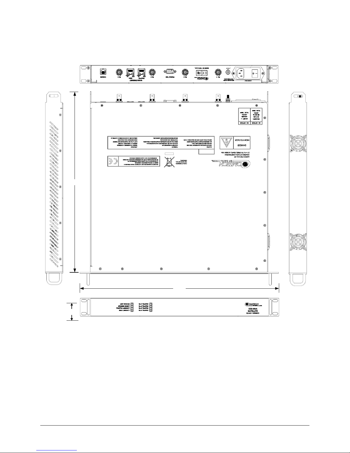
Figure 1-5. CDD-564AL Dimensional Envelope ....................................................................................... 1–6
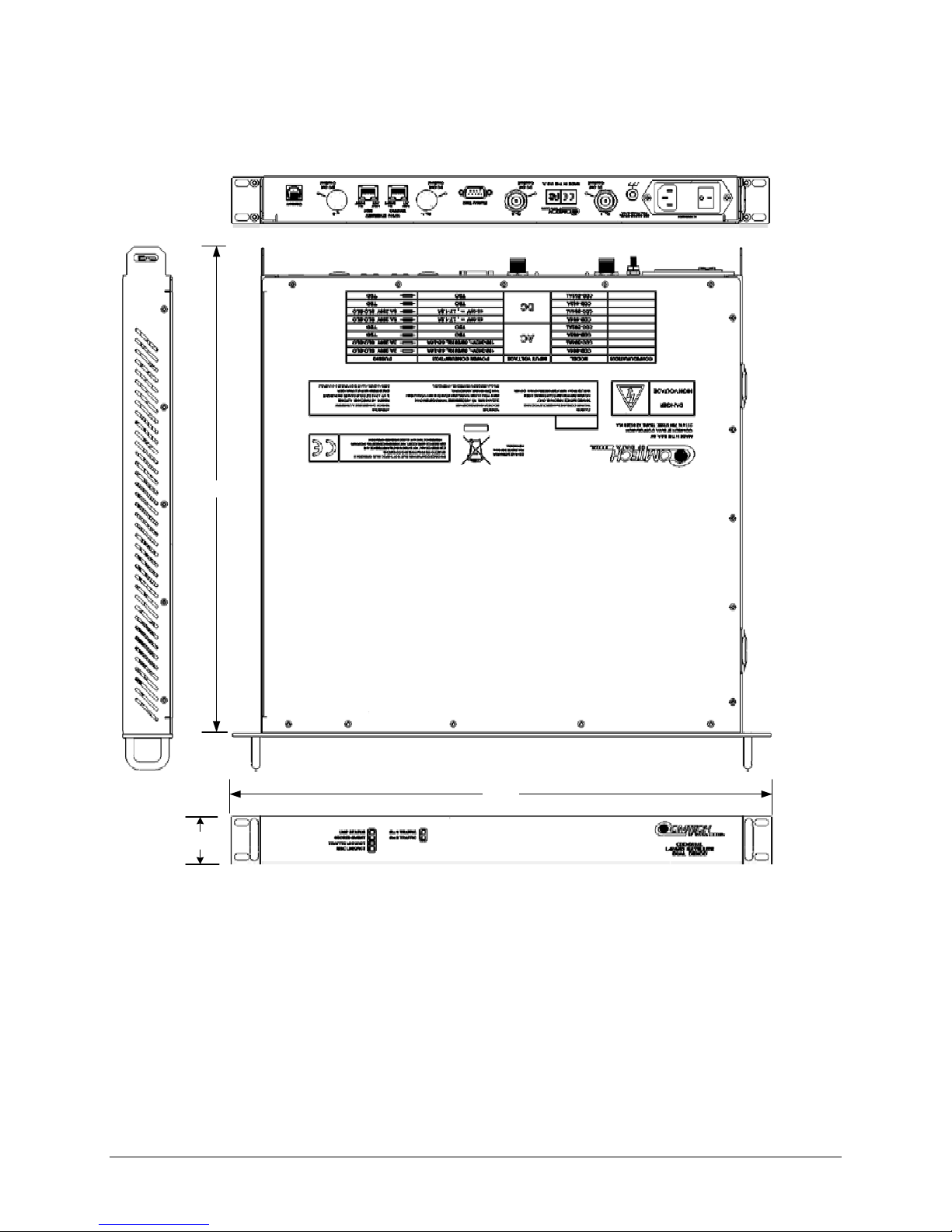
Figure 1-6. CDD-564A Dimensional Envelope ......................................................................................... 1–7
Figure 1-7. CDD-562AL Dimensional Envelope ....................................................................................... 1–8
Figure 1-8. Front Panel Views................................................................................................................... 1–9
Figure 1-9. CDD-564AL Rear Panel View .............................................................................................. 1–10
Figure 1-10. CDD-564A Rear Panel View .............................................................................................. 1–11
Figure 1-11. CDD-562AL Rear Panel View ............................................................................................ 1–12
Figure 2-1. Unpacking and Inspecting the Shi pm ent ................................................................................ 2–1
Figure 2-2. Installation into a Rack Enclosure .......................................................................................... 2–3
Figure 2-3. Optional Rear Support Brackets Kit Installation ..................................................................... 2–4
Figure 3-1. CDD-56xA/L Rear Panel Views .............................................................................................. 3–1
Figure 3-2. CDD-56xA/L AC Power Interface ........................................................................................... 3–7
Figure 3-3. Applying AC Power to the CDD-56xA/L ................................................................................. 3–7
Figure 3-4. Replacing CDD-56xA/L AC Fuses.......................................................................................... 3–8
Figure 3-5. CDD-56xA/L DC Power Interface ........................................................................................... 3–9
Figure 3-6. Applying DC Power to the CDD-56xA/L ................................................................................. 3–9
Figure 3-7. Replacing CDD-56xA/L DC Fuses ....................................................................................... 3–10
Figure 4-1. (CDD-562L) Router Mode Point-to-Point Diagram ................................................................ 4–9
Figure 4-2. (CDD-564/564L) Point-to-Point Router Working Mode Diagram ........................................ 4–10
Figure 4-3. (CDD-562L) Point-to-Multipoint Router Working Mode Diagram ........................................ 4–11
Figure 4-4. (CDD-564/564L) Point-to-Multipoint Router Working Mode Diagram ................................. 4–12
Figure 5-1. CDD-564A/L Rear Panel Connections to User PC ................................................................ 5–2
Figure 8-1. CLI Main Menu via Telnet or PuTTY (CDD-564A /L sho wn) ................................................... 8–3
Figure 8-2. Router Mode Point-to-Point System Confi gurat i on ................................................................ 8–5
Figure 10-1. CDD-56xAL Home page example ...................................................................................... 10–5
Figure 10-2. Home | Contact page .......................................................................................................... 10–6
Figure 10-3. Admin | Access page .......................................................................................................... 10–7
Figure 10-4. Admin | SNMP page ........................................................................................................... 10–9
Figure 10-5. Admin | Working Mode page ............................................................................................ 10–10
Figure 10-6. Admin | Features page ..................................................................................................... 10–11
Figure 10-7. Admin | Save page ........................................................................................................... 10–16
Figure 10-8. Admin | Reboot page ........................................................................................................ 10–17
Figure 10-9. Configuration | Demod page ............................................................................................. 10–18
Figure 10-10. Configuration | Utilities pa ge ........................................................................................... 10–32
Figure 10-11. Configuration | LNB page ............................................................................................... 10–34
Figure 10-12. Status | Demod Status page ........................................................................................... 10–35
Figure 10-13. Status | System Logs | Events Log page ........................................................................ 10–36
Figure A-1. VersaFEC Codes versus Shannon Capacity ......................................................................... A–4
Figure A-2. Turbo Product Code Rate 5/16 BPS K ................................................................................... A–8
Figure A-3. Turbo Product Codec Rate 21/44 BPSK/QPSK ..................................................................... A–9
Figure A-4. Turbo Product Codec Rate 3/4 QP S K, 8-PSK/8-QAM, and 16-QAM .................................. A–10
Figure A-5. Turbo Product Codec Rate 7/8 QP S K, 8-PSK/8-QAM, and 16-QAM .................................. A–11
Figure A-6. Turbo Product Codec Rate 0.95 QP S K and 8-PSK/Q-QAM ............................................... A–12
Figure A-7. VersaFEC Codec Rate 0.488 BPSK .................................................................................... A–13
Figure A-8. VersaFEC Codec Rates 0.533, 0.631, 0.706, and 0.803 QPSK ......................................... A–14
Figure A-9. VersaFEC Codec Rates 0.642, 0.711, and 0.780 8-QAM ................................................... A–15
Figure A-10. VersaFEC Codec Rates 0.731, 0.780, 0.829, and 0.853 16-QAM .................................... A–16
Figure C-1. CDD-564AL Multi-Channel Demodulator Example ............................................................... C–1
Figure C-2. CDD-564A/L Dedicated Management Port Operation .......................................................... C–2
ix
Page 16

CDD-562AL/564A/L Multi-Channel Dem odulator Revision 0
Table of Contents MN-CDD562AL564AL
Figure C-3. CDD-564A/L Dedicated Management Port Configurat i on .................................................... C–3
Figure C-4. CDD-564A/L Router Mode IP Addresses ............................................................................. C–4
Figure C-5. CDD-564A/L Router Mode – Assign IP Addresses .............................................................. C–5
Figure C-6. CDD-564A/L Route Tables ................................................................................................... C–6
x
Page 17
CDD-562AL/564A/L Multi-Channel Dem odulator Revision 0
WARNING
CAUTION
CAUTION
Preface MN-CDD562AL564AL
PREFACE
About this Manual
This manual is intended for the persons who operate and maintain these Comtech EF Data products.
• CDD-562AL (L-Band) Dual Demodulator
• CDD-564A (70/140 MHz IF) Quad Demodulator
• CDD-564AL (L-Band) Quad Demodulator
These demodulators include support for externally connected Low-Noise Block Downconverters (LNBs).
Warnings, Cautions, and Notes
indicates a potentially hazardous situation that, if not avoided, could result in death
or serious injury.
indicates a hazardous situation that, if not avoided, may result in minor or moderate
injury. CAUTION may also be used to indicate other unsafe practices or risks of property
damage.
NOTE: Type in the note text here.
Patents and Trademarks
See all of Comtech EF Data's Patents and Patents Pending at http://patents.comtechefdata.com.
Comtech EF Data acknowledges that all trad emarks are the property of the trademark owners.
Electrical Safety and Compliance
The unit complies with the IEC 60950 Safety of Information Technology Equipment (Including Electrical
Business Machines) safety standard.
If the unit is operated in a vehicle or movable installation, make sure the unit is stable.
Otherwise, IEC 60950 safety is not guaranteed.
xi
Page 18
CDD-562AL/564A/L Multi-Channel Dem odulator Revision 0
CAUTION
CAUTION
Preface MN-CDD562AL564AL
Electrical Installation
The equipment is rated for operation over the range 100 - 240 volts AC. It has a maximum power
consumption of 106 Watts (when all inputs are supplying DC to LNBs), and draws a maximum of 1.5
Amps.
The installation and connection to the line supply must be made in compliance to local or national wiring
codes and regulations.
The CDD-562AL/564A/L is shipped with a line inlet cable suitable for use in the country of operation. If
it is necessary to replace this cable, ensure the replacement has an equivalent specifi cation.
Examples of acceptable ratings for the cable include HAR, BASEC and HOXXX-X.
Examples of acceptable connector ratin gs include VDE, NF-USE, UL, CSA, OVE, CEBEC, NEMKO,
DEMKO, BS1636A, BSI, SETI, IMQ, KEMA-KEUR and SEV.
Fuses
See Chapter 3 for correct fuse type specifications.
For continued operator safety, always replace the fuses with the correct type and rating.
Grounding
The installation instructions require that the integrity of the protective earth must be ensured and that the
equipment shall be connected to the protective earth connection at all times.
The CDD-562AL/564A/L is designed for connection to a power system that has separate ground, line and
neutral conductors. The equipment is not
connection to ground. It is therefore imperative
user to ensure that the unit has been properly grounded using the ground stud provided on the rear panel
of the unit.
Correct grounding protection is required.
designed for connection to a power system that has no direct
during installation, configuration, and operation for the
xii
Page 19

CDD-562AL/564A/L Multi-Channel Dem odulator Revision 0
CAUTION
Preface MN-CDD562AL564AL
Operating Environment
Do not operate the unit in any of these extreme operating conditions:
• Ambient temperatures less than 0°C (32°F) or more than 50°C (122°F). (maximum
storage temperature allowed is -25°C (-13°F) to 85°C (185°F)).
• Precipitation, condensation, or humid atmospheres of more than 95% relative humidity.
• Unpressurized altitudes of more than 2000 metres (6561.7 feet).
• Excessive dust.
• Flammable gases.
• Corrosive or explosive atmospheres.
European Union Radio Equipment and Telecommunications Terminal
Equipment (R&TTE) Directive (1999/5/EC) and EN 301 489-1
Independent testing verifies that the unit complies with the European Union R&TTE Directive, its
reference to EN 301 489-1 (Electromagnetic compatibility and Radio spectrum Matters [ERM];
ElectroMagnetic Compatibility [EMC] standard for radio equipment and services, Part 1: Common
technical requirements), and the Declarations of Conformity for the applicable direct ives, standards, and
practices that follow.
• Use coaxial cable that is of good quality (e.g., RG58/U (50Ω) or RG59/U (75Ω)) for connections
to the IF Tx and Rx (transmit and receive) BNC female connectors.
• Use Type 'D' conn ectors that have back-shells with continuous metallic shielding.
• Type ‘D’ cabling must have a continuous outer shield (either foil or braid, or both). The shield
must be bonded to the back-shell.
• Operate the unit with its cover on at all times.
EMC (Electromagnetic Compatibility)
In accordance with European Directive 2004/108/EC, independent testing showed that the
CDD-562AL/564A/L complied with these standards:
Emissions
Immunity
EN 55022 Class B - Limits and methods of measu rement of radio interference
characteristics of Information Technolog y Equipment
(Also tested to FCC Part 15 Class B)
EN 55024 – Information Technology Equipment: Immunity Characteristics, Limits, and
Methods of Measurement
xiii
Page 20
CDD-562AL/564A/L Multi-Channel Dem odulator Revision 0
!
Preface MN-CDD562AL564AL
Additionally, the CDD-562AL/564A/L complied with these standards:
EN 61000-3-2 Harmonic Currents Emission EN 61000-4-6 RF Conducted Immunity
EN 61000-3-3 Voltage Fluctuations and Flicker EN 61000-4-11 Voltage Dips, Interruptions, and
Variations Immunity
EN 61000-4-2 ESD Immunity EN 61000-4-3 Radiated Immunity
EN 61000-4-4 EFT Burst Immunity
EN 61000-4-5 Surge Immunity
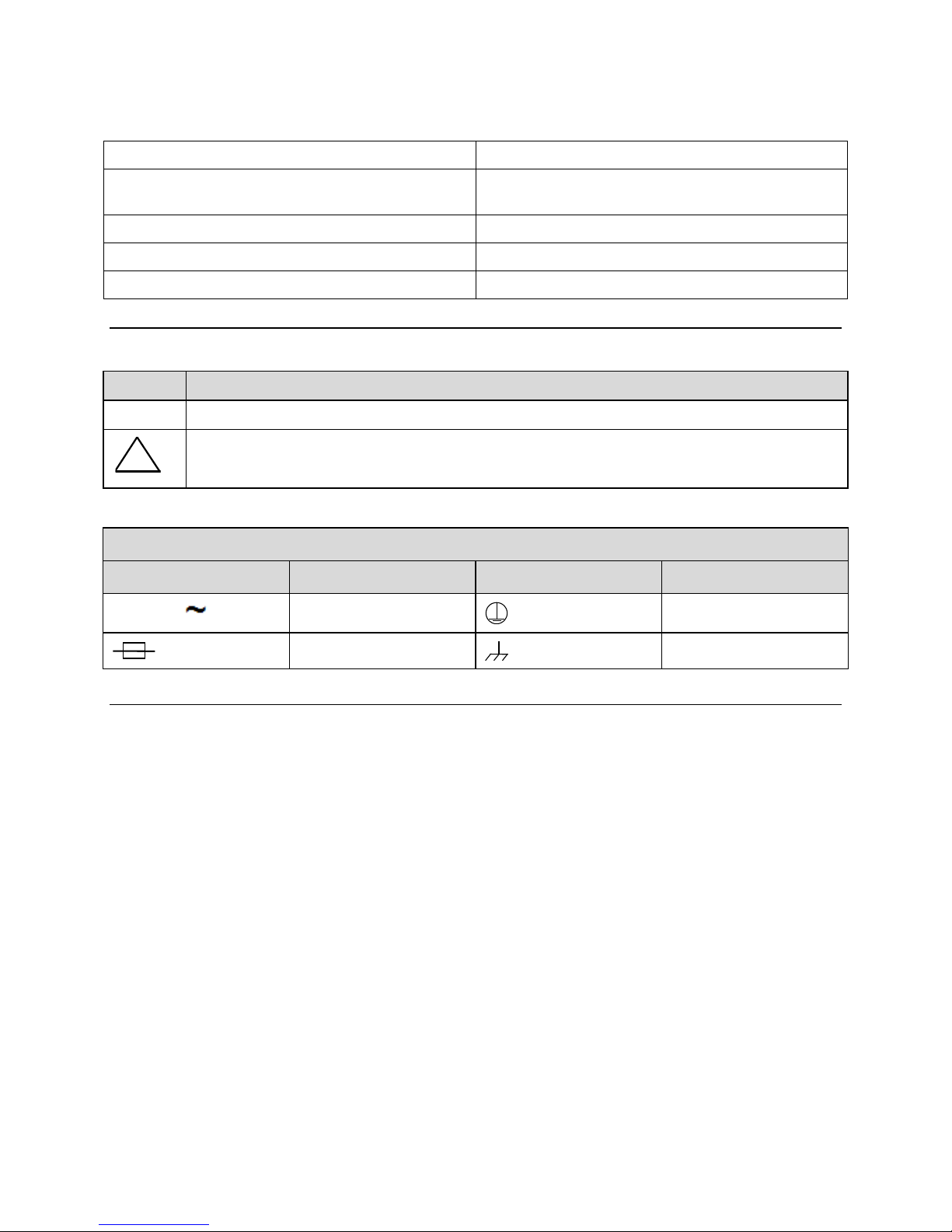
European Union Low Voltage Directive (LVD) (2006/95/EC)
Symbol Description
<HAR> Type of power cord required for use in the European Community.
CAUTION: Double-pole/Neutral Fusing
ACHTUNG: Zweipolige bzw. Neutralleiter-Sicherung
International Symbols
Symbol Definition Symbol Definition
Alternating Current
Fuse
Protective Earth
Chassis Ground
European Union RoHS Directive (2011/65/EC)
This unit satisfies (with exemptions) the requirements specified in the European Union Directive on the
Restriction of Hazardous Substances in Electrical and Electronic Equip ment (EU RoHS, Directive
2011/65/EC).
European Union Telecomm u nicat i on s Ter mi nal Eq uipment Directive
(91/263/EEC)
In accordance with the European Union Telecommunications Terminal Equipment Directive 91/263/EEC,
the unit should not be directly connected to the Public Telecommunications Network.
CE Mark
Comtech EF Data declares that the CDD-562AL/564A/L meets the necessary requir ements for the CE
Mark.
xiv
Page 21

CDD-562AL/564A/L Multi-Channel Dem odulator Revision 0
Preface MN-CDD562AL564AL
Federal Communications Commission
Federal Code of Regulation FCC Part 15, Subpart B.
Product Support
For all product support, please call:
+1.240.243.1880
+1.866.472.3963 (toll free USA)
Comtech EF Data Headquarter s
http://www.comtechefdata.com
Comtech EF Data Corp.
2114 West 7th Street
Tempe, Arizona USA 85281
+1.480.333.2200
xv
Page 22

CDD-562AL/564A/L Multi-Channel Dem odulator Revision 0
Preface MN-CDD562AL564AL
Warranty Policy
Comtech EF Data products are warranted against defects in material and workmanship for a specific period from the date of
shipment, and this period varies by product. In most cases, the warranty period is two years. During the warranty period,
Comtech EF Data will, at its option, repair or replace products that prove to be defective. Repairs are warranted for the remainder
of the original warranty or a 90 day extended warranty, whichever is longer. Contact Comtech EF Data for the warranty period
specific to the product purchased.
For equipment under warranty, the owner is responsible for freight to Comtech EF Data and all related customs, taxes, tariffs,
insurance, etc. Comtech EF Data is responsible for the freight charges only for return of the equipment from the factory to the
owner. Comtech EF Data will return the equipment by the same method (i.e., Air, Express, Surface) as the equipment was sent to
Comtech EF Data.
All equipment returned for warranty repair must have a valid RMA number issued prior to return and be marked clearly on the
return packaging. Comtech EF Data strongly recommends all equipment be returned in its original packaging.
Comtech EF Data Corporation’s obligations under this warranty are limited to repair or replacement of failed parts, and the return
shipment to the buyer of the repaired or replaced parts.
Limitations of Warranty
The warranty does not apply to any part of a product that has been installed, altered, repaired, or misused in any way that, in the
opinion of Comtech EF Data Corporation, would affect the reliability or detracts from the performance of any part of the product,
or is damaged as the result of use in a way or with equipment that had not been previously approved by Comtech EF Data
Corporation.
The warranty does not apply to any product or parts thereof where the serial number or the serial number of any of its parts has
been altered, defaced, or removed.
The warranty does not cover damage or loss incurred in transportation of the product.
The warranty does not cover replacement or repair necessitated by loss or damage from any cause beyond the control of Comtech
EF Data Corporation, such as lightning or other natural and weather related events or wartime environments.
The warranty does not cover any labor involved in the removal and or reinstallation of warranted equipment or parts on site, or
any labor required to diagnose the necessity for repair or replacement.
The warranty excludes any responsibility by Comtech EF Data Corporation for incidental or consequential damages arising from
the use of the equipment or products, or for any inability to use them either separate from or in combination with any other
equipment or products.
A fixed charge established for each product will be imposed for all equipment returned for warranty repair where Comtech EF
Data Corporation cannot identify the cause of the reported failure.
Exclusive Remedies
Comtech EF Data Corporation’s warranty, as stated is in lieu of all other warranties, expressed, implied, or statutory, including
those of merchantability and fitness for a particular purpose. The buyer shall pass on to any purchaser, lessee, or other user of
Comtech EF Data Corporation’s products, the aforementioned warranty, and shall indemnify and hold harmless Comtech EF
Data Corporation from any claims or liability of such purchaser, lessee, or user based upon allegations that the buyer, its agents,
or employees have made additional warranties or representations as to product preference or use.
The remedies provided herein are the buyer’s sole and exclusive remedies. Comtech EF Data shall not be liable for any direct,
indirect, special, incidental, or consequential damages, whether based on contract, tort, or any other legal theory.
xvi
Page 23
CDD-562AL/564A/L Multi-Channel Dem odulator Revision 0
Introduction MN-CDD562AL/564AL
Chapter 1. INTRODUCTION
1.1 Overview
Equipped with an IP router, these demodulators are applicable to closed network applications.
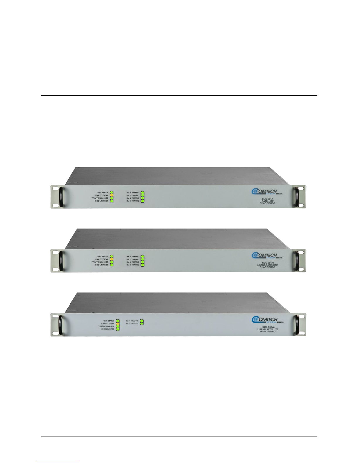
• CDD-564A is a quad (4-channel) 70/140 MHz IF satellite demodulator
• CDD-564AL is a quad (4-channel) L-Band satellite demodulator
• CDD-562AL is a dual (2-channel) L -B and satellite demodulator
Figure 1-1. CDD-564A 70/140 MHz IF Satellite Quad Demodulator
Figure 1-2. CDD-564AL L-Band Satellite Quad Demodulator
Figure 1-3. CDD-562AL L-Band Satellite Dual Demodulator
Both frequency versions serve as replacements for the CDD-564L/CDD-562L (L-Band) or CDD564(70/140 MHz) Satellite Demodulators. They are 100% backwards compatible with their predecessors,
but incorporate new features and exp ansion capabilities.
Unless otherwise specified, these pr oducts are referred to collectively throughout this manual as the
CDD-56xA/L.
1–1
Page 24

CDD-562AL/564A/L Multi-Channel Dem odulator Revision 0
Introduction MN-CDD562AL/564AL
1.1.1 CDD-56xA/L Features
The CDD-56xA/L has many standard and optional features:
• Fast acquisition demodulator
• The CDD-564A:
o Provides a 70/140 MHz IF frequency range from 50 to 90 MHz and 100 to 180 MHz.
• The CDD-564AL:
o Provides an L-Band IF frequency range from 950 to 2250 MHz.
o Supports external Low-Noise Block Down Converters (LNBs).
o Consumes only 55 Watts (without LNB).
• The CDD-564A/L is equipped for 10/100 BaseT Ethernet operation with a number of key
features for Wide Area Network (WAN) bandwidth optimization: very low overhead High-Level
Data Link Control (HDLC) encapsulation, Header and Payload Decompression.
• The CDD-564A/L offers variable data rates from 16 kbps to 10.239 Mbps, in BPSK, QPSK, 8-
PSK, 8-QAM, and 16-QAM modes.
• The CDD-564A/L provides, as Forward Error Correction (FEC) options: Turbo Product Coding
(TPC, IESS-315 compliant), ULL (Ultra Low Latency), and VersaFEC® (a short-block, low
latency Low-density Parity Check Coding (LDPC)).
• The CDD-564A/L is compact – it is 1RU high, with a depth of 17.25 inches
• The CDD-564A/L has an integrated 10/100 BaseT Ethernet interface for network-based remote
product M&C – including SNMP, HTTP (non-secure Web server), and Telnet.
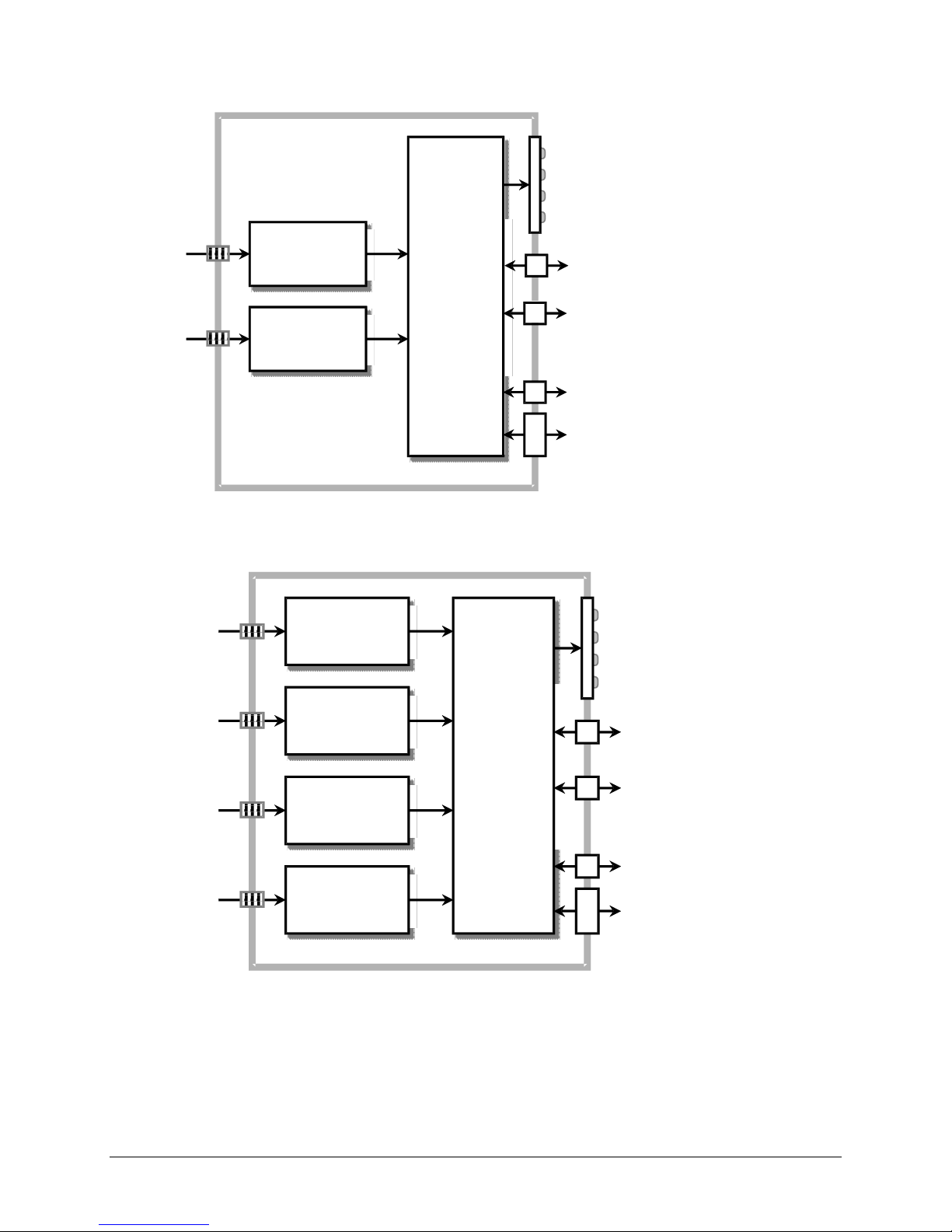
1.2 Functional Descript ion
The demodulator has three interface types: IF Ethernet (data), Traffic Ethernet (data) and M&C 100
(Dedicated Management Port).
• The IF interface provides independent unidirectional links (Rx only) with the satellite via the
downlink equipment.
• The Traffic Ethernet interface is a bidirectional path, which connects with the customer’s
equipment through an Ethernet Switch. The Ethernet interface is a 10/100 BaseT Ethernet port
where data flow is the combined output of the demodulator channels. Control and status
information also uses this port, if the Dedicated Management Port is disabled.
• The M&C Ethernet interface is a 10/100 Ethernet Port. It is used only for managing the modem
over Web/SNMP/Telnet when Dedicated Management Port operation is enab led. The modem can
be managed only through this M&C Ethernet port when Dedicated Management Port operation is
enabled. In Dedicated Management Port mode, the Traffic 100 port aggregates the data from all
demodulators, and the unit is not accessible for M&C, except through the M&C 100 port.
The10/100 Ethernet M&C port is inactive when Dedicated Management Port operation is
disabled.
In both L-Band and 70/140 MHz operation, receive signals are first converted to a UHF frequency for
SAW filtering. Then, they are down converted to a lower IF frequency for direct sampling in a high speed
1–2
Page 25

CDD-562AL/564A/L Multi-Channel Dem odulator Revision 0
Introduction MN-CDD562AL/564AL
A/D converter. An AGC circuit contro ls the signal level presented to the A/D conver ter. Digital signal
processing does the final quadrature conversion to baseband, followed by Nyquist filtering, carrier
recovery and symbol timing recovery. The resulting demodulated signal is fed, in soft decision form, to
the selected FEC decoder. The FEC decoder can be TPC or VersaFEC.
After decoding, the recovered clock and data pass to the IP Module. In the IP Module, traffic is examined
and processed for four channels before it is delivered to the Ethernet port.
The demodulator’s signal processing functions occur in two, large Field-Programmable Gate Arrays
(FPGA). This permits rapid implementation of changes, additions and enhancements in the field. These
signal-processing functions are controlled and monitored by a 32-bit RISC microprocessor, which also
controls serial and Ethernet interfaces.
As shown in the block diagrams in Figure 1-3, the demodulator is comprised of a single printed circuit
board assembly with integral FEC and IP router.
1–3
Page 26
CDD-562AL/564A/L Multi-Channel Dem odulator Revision 0
Demodulator
1
Demodulator
2
Demodulator
3
Demodulator
4
Packet
Processor
&
Micro
-
Controller
CDD
-
564A/L
Inputs
Front Panel
LEDs (8)
Traffic
10/100 Ethernet
Command Line
Interface (RJ
-
11)
DB - 9
Factory Test Port
M&C
10/100 Ethernet
Demodulator
1
Demodulator
2
Packet
Processor
&
Micro
-
Controller
CDD
-
562AL
L - Band
Inputs
Front Panel
LEDs (6)
10/100 BaseT
Ethernet (RJ-45)
Command Line
Interface (RJ-11)
DB - 9
Factory Test Port
M&C
Introduction MN-CDD562AL/564AL
10/100 BaseT
CDD-562AL Block Diagram
CDD-564A/L Block Diagram
Figure 1-4. CDD-5xxA/L Block Diagrams
1–4
Page 27
CDD-562AL/564A/L Multi-Channel Dem odulator Revision 0
Introduction MN-CDD562AL/564AL
1.3 Features
1.3.1 Physical Description
The demodulator is a 1RU-high chassis. You can install it into a rack or as a free standing unit. Handles at
the front help with rack installation.
1.3.2 Major Assemblies
Model Assembly Description
PL-0021662 AC Chassis
CDD-564AL
CDD-564A
CDD-562AL
PL-0021314 DC Chassis
PL-0021861 Quad Demodulator Card
PL-0021412 0.95 Turbo Product Codec Card, optional
PL-0021666 AC Chassis, IF
PL-0021715 DC Chassis, IF
PL-0021660 Quad Demodulator Card
PL-0021412 0.95 Turbo Product Codec Card, optional
PL-0022006 AC Chassis
PL-0022045 DC Chassis
PL-0021863 Dual Demodulator Card
1.3.3 Interoperability/Compatibility
The demodulator works with the Comtech EF Data Satellite Modems that have the optional IP
Module/router:
• CDM-570/L-IP
• CDM-570A/L-IP
The demodulator supports the receive functions of the equipment.
1–5
Page 28
CDD-562AL/564A/L Multi-Channel Dem odulator Revision 0
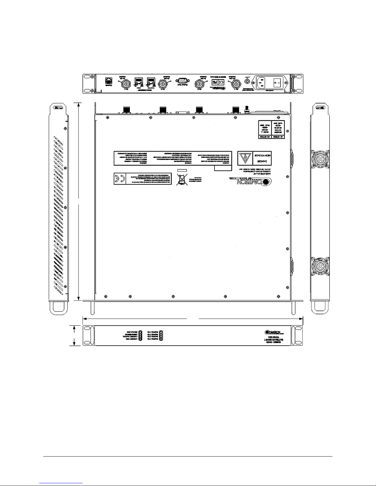
19.00
1.72
17.25
Introduction MN-CDD562AL/564AL
1.3.4 Dimensional Envelopes
Figure 1-5. CDD-564AL Dimensional Envelope
1–6
Page 29
CDD-562AL/564A/L Multi-Channel Dem odulator Revision 0
1.72
19.00
17.00
Introduction MN-CDD562AL/564AL
Figure 1-6. CDD-564A Dimensional Envelope
1–7
Page 30
CDD-562AL/564A/L Multi-Channel Dem odulator Revision 0
17.00
1.72
19.00
Introduction MN-CDD562AL/564AL
Figure 1-7. CDD-562AL Dimensional Envelope
1–8
Page 31
CDD-562AL/564A/L Multi-Channel Dem odulator Revision 0
Introduction MN-CDD562AL/564AL
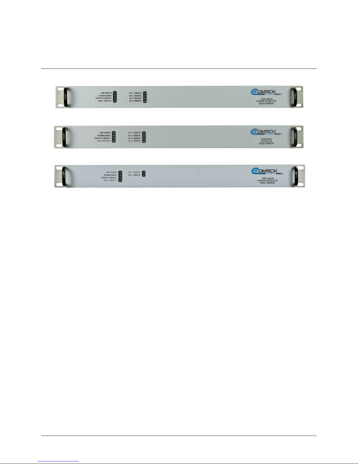
1.3.5 Physical Features
1.3.5.1 Front P anel
CDD-564AL
CDD-564A
CDD-562AL
Figure 1-8. Front Panel Views
Figure 1-8 shows the front panel of the demodulators. Depending on the unit, the front panel has six
(CDD-562AL) or eight (CDD-564A/L) Light-Emitting-Diode (LED) indicators.
The LEDs indicate the status of the unit:
• Overall Unit Status
• Stored Event
• Traffic Ethernet Link Activity
• M&C Link Ethernet Activity for the dedicated management port
• Traffic Status for each of the two (CDD-562AL) or four (CDD-564A/L) Rx Traffic (receive)
channels
1–9
Page 32

CDD-562AL/564A/L Multi-Channel Dem odulator Revision 0
CAUTION
Introduction MN-CDD562AL/564AL
1.3.5.2 Rear Panel
External cables are attached to connectors on the rear panel of the unit.
See also: Chapter 3. Rear Panel Connectors and Pinouts.
The European EMC Directive (EN55022, EN50082-1) requires using properly shielded
cables for DATA I/O. These cables must be double-shielded from end-to-end, ensuring
a continuous ground shield.
Figure 1-9. CDD-564AL Rear Panel View
CDD-564AL (L-Band)
Name Type Function
AC
Chassis power
DC (Optional)
Ground #10-32 stud Common Chassis Ground
Rx 1 Type N female
Rx 2 Type N female
L-Band Input
Rx 3 Type N female
Rx 4 Type N female
Factory Test 9-pin Type D male Remote Interface (EIA-232) for Factory Test
Traffic RJ-45 female Ethernet Traffic
M&C RJ-45 female M&C Port
Console RJ-11 female Async Serial Console Port
1–10
Page 33

CDD-562AL/564A/L Multi-Channel Dem odulator Revision 0
Introduction MN-CDD562AL/564AL
Figure 1-10. CDD-564A Rear Panel View
CDD-564A (IF)
Name Type Function
AC
Chassis power
DC (Optional)
Ground #10-32 stud Common Chassis Ground
Rx 1 BNC female
Rx 2 BNC female
IF Input
Rx 3 BNC female
Rx 4 BNC female
Factory Test 9-pin Type D male Remote Interface (EIA-232) for Factory Test
Traffic RJ-45 female Ethernet Traffic
M&C RJ-45 fem al e M&C Port
Console RJ-11 female Async Serial Console Port
1–11
Page 34

CDD-562AL/564A/L Multi-Channel Dem odulator Revision 0
Introduction MN-CDD562AL/564AL
Figure 1-11. CDD-562AL Rear Panel View
CDD-562L (L-Band)
Name Type Function
AC
Chassis power
DC (Optional)
Ground #10-32 stud Common Chassis Ground
Rx 1 Type N female
L-Band Input
Rx 2 Type N female
Factory Test 9-pin Type D male Remote Interface (EIA-232) for Factory Test
10/100 Ethernet RJ-45 female Et hernet Traffic
M&C RJ-45 female M&C Port
Console RJ-11 female Async Serial Console Port
1.3.6 Data Interfaces
The demodulators include two 10/100 BaseT Ethernet ports. One port is a terrestrial data interface for IP
traffic. A separate port is for the management an d control interface (the HTTP Web Server Int er f ace).
1.3.7 Updating Demodulator Firmware
The modem uses flash memory technology internally. This simplifies firmware updating – you can
perform the update, without opening the unit, simply by connecting the modem to any 10/100 Base T
Ethernet port on a user-supplied PC once you establish Ethernet connectivity. You can receive firmware
updates via download over the Internet (from Comtech EF Data’s website), or from Comtech EF Data
Product Support through e-mail or standard mail delivery on CD.
See Also: Chapter 5. Updating Firmware
1–12
Page 35

CDD-562AL/564A/L Multi-Channel Dem odulator Revision 0
Introduction MN-CDD562AL/564AL
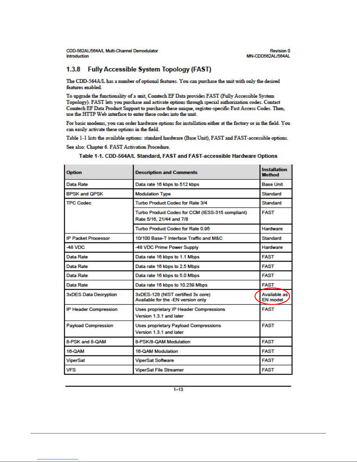
1.3.8 Fully Accessible System T opology (FAST)
The CDD-564A/L has a number of optional features. You can purchase the unit with only the desired
features enabled.
To upgrade the functionality of a unit, Comtech EF Data provides FAST (Fully Accessible System
Topology). FAST lets you purchase and activate options through special authorization codes. Contact
Comtech EF Data Product Support to purchase these unique, register-specific Fast Access Codes. Then,
use the HTTP Web interface to enter these codes in to the unit.
For basic modems, you can order hardware options for installation either at the factory or in the field. You
can easily activate these options in the field.
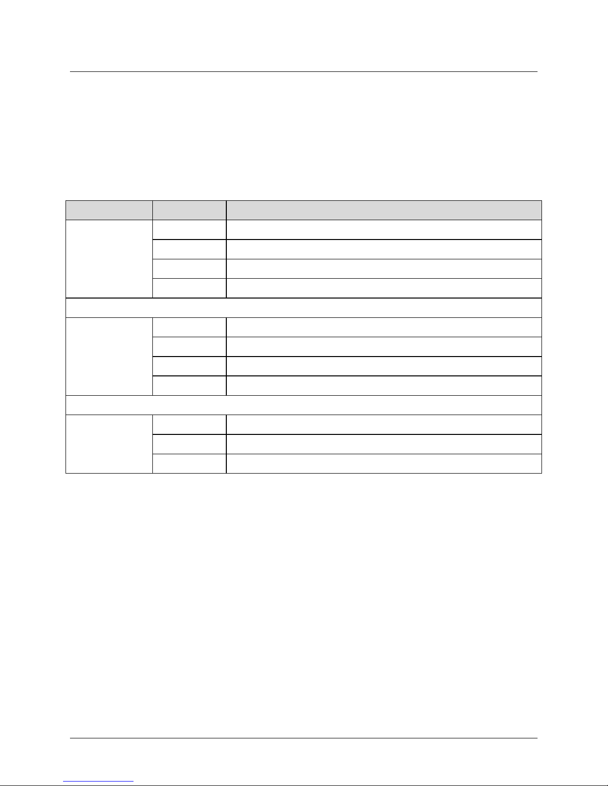
Table 1-1 lists the available options: standard hardware (Base Unit), FAST and FAST-accessible options.
See also: Chapter 6. FAST Activation Procedure.
Table 1-1. CDD-564A/L Standard, FAST and FAST-accessible Hardware Options
Option Description and Comments
Data Rate Data rate 16 kbps to 512 kbps Base Unit
BPSK and QPSK Modulation Type Standard
TPC Codec Turbo Product Codec for Rate 3/4 Standard
Turbo Product Codec for CCM (IESS-315 compliant)
Rate 5/16, 21/44 and 7/8
Turbo Product Codec for Rate 0.95 Hardware
IP Packet Processor 10/100 Base-T Interface Traffic and M&C Standard
-48 VDC -48 VDC Prime Power Supply Hardware
Data Rate Data rate 16 kbps to 1.1 Mbps FAST
Data Rate Data rate 16 kbps to 2.5 Mbps FAST
Data Rate Data rate 16 kbps to 5.0 Mbps FAST
Data Rate Data rate 16 kbps to 10.239 Mbps FAST
3xDES Data Decryption 3xDES-128 (NIST certified 3x core)
Available for the -EN version only
Installation
Method
FAST
FAST
IP Header Compression Uses proprietary IP Header Compressions
Payload Compression Uses proprietary Payload Compressions
8-PSK and 8-QAM 8-PSK/8-QAM Modulation FAST
16-QAM 16-QAM Modulation FAST
ViperSat ViperSat Software FAST
FAST
Version 1.3.1 and later
FAST
Version 1.3.1 and later
1–13
Page 36

CDD-562AL/564A/L Multi-Channel Dem odulator Revision 0
Introduction MN-CDD562AL/564AL
Option Description and Comments
VFS ViperSat File Streamer FAST
Installation
Method
1.4 Summary of Specif ications
1.4.1 Demodulator
Parameters Specifications
Modulation BPSK, QPSK, 8-PSK, 8-QAM and 16-QAM
Symbol Rate Range 16Ksps to 3.0 Msps
Data Rate Range 16 kbps to 10.239 Mbps
Operating Modes
FEC None: Uncoded BPSK/QPSK
• Turbo Product Codec – 2nd Generation Rates 21/44, 5/16, 3/4, 7/8,
and 0.95 (optional plug-in module for rate 0.95)
• VersaFEC® Codec (short-block, low latency and ultra-low-latency
LDPC)
Turbo Product Codec, 4-bit soft-decision:
Rate 5/16 BPSK – 2 dimensional
Rate 21/44 BPSK – 3 dimensional
Rate 21/44 QPSK – 3 dimensional
Rate 3/4 QPSK/8-PSK/8-QAM/16-QAM – 2 dimensional
Rate 7/8 QPSK/8-PSK/8-QAM/16-QAM – 2 dimensional
Rate 0.95 (optional plug-in card) QPSK/8-QAM/8-PSK –
2 dimensional eTPC (exact Code Rate is act ual l y 17/18, or 0.944)
VersaFEC Codec, 6-bit soft-decision (FAST Option):
Rate 0.488 BPSK (also 0.493 BPSK Ultra-Low-Latency
Rate 0.533, 0.631, 0.706, 0.803 QPSK (0.493, 0.654, 0.734 Ultra-
Low-Latency
Rate 0.642, 0.711, 0.780 8-QAM (also 0.576 8-QA M Extended
CCM
Rate 0.731, 0.780, 0.829, 0.853 16-QAM (also 0.644 16-QAM
Extended CCM
Scrambling Transparent Closed Network mode - per ITU V.35 (Intelsat variant)
Turbo Product Code mode - externally frame syn chronized – proprietary
Acquisition Range
Acquisition Time Highly dependent on data rate, FEC rate, and demodulator acquisition
±1 to ±32 kHz, programmable in 1 kHz increments, for symbol rates
below 625 ksymbols/sec
±1 to ±200 kHz, 1 kHz increments, for symbol rates above 625
ksymbols/sec, L-Band only
range.
1–14
Page 37

CDD-562AL/564A/L Multi-Channel Dem odulator Revision 0
Introduction MN-CDD562AL/564AL
Parameters Specifications
Monitor Functions Eb/No estimate, 2 to 16 dB (± 0.25 dB accuracy)
Corrected Bit Error Rate, 1E-3 to 1E-9
Frequency offset, ± 200 kHz range, 100 Hz resolution
Receive signal level monitor accuracy: ± 5 dB for CDD-564AL L-Band, ± 3
dB for CDD–564A over specified min to max signal range
LNB Voltage and Current
Clocking Options
Internal – CDD-564AL (L-Band)±0.06 ppm (SCT); CDD-564A (70/140
MHz) ±1.0 ppm (SCT)
External – None
Input Impedance 50Ω or 75Ω with 17 dB minimum return loss
1–15
Page 38

CDD-562AL/564A/L Multi-Channel Dem odulator Revision 0
TURBO Product Codec
21/44 (QPSK)
21/44 (BPSK)
5/16 (BPSK)
TURBO Product Codec
Rate 0.95 (QPSK)
Rate 0.95 (8-PSK)
TURBO Product Codec
Rate 3/4 (8-QAM)
Rate 7/8 (8-QAM)
Rate 0.95 (8-QAM)
VersaFEC Codec BPSK
0.488 (BPSK)
VersaFEC Codec 8-QAM
0.642 (8-QAM)
0.711 (8-QAM)
0.780 (8-QAM)
VersaFEC Codec 16-QAM
0.731 (16-QAM)
0.780 (16-QAM)
0.829 (16-QAM)
0.853 (16-QAM)
Introduction MN-CDD562AL/564AL
1.4.1.1 BER Perf or ma nc e Sp eci fi c at i ons
BER Description
Rate 21/44 QPSK
Rate 21/44 BPSK
Rate 5/16 BPSK
(See Note 1)
TURBO Product Codec
Rate 3/4 QPSK
Rate 3/4 8-PSK
Rate 3/4 16-QAM
(See Note 1)
TURBO Product Codec
Rate 7/8 QPSK
Rate 7/8 8-PSK
Rate 7/8 16-QAM
(See Note 1)
Rate 0.95 QPSK
Rate 0.95 8-PSK
(See Note 1)
For
BER=
-6
10
-7
10
-8
10
-6
10
-7
10
-8
10
-6
10
-7
10
-8
10
10-6
-7
10
-8
B10
Guaranteed Eb/No (typical value in parentheses)
2.9 dB (2.6 dB)
3.1 dB (2.7 dB)
3.3 dB (2.8 dB)
3/4 (QPSK)
3.8dB (3.4dB)
4.1dB (3.7dB)
4.4dB (4.0dB)
Rate 7/8 (QPSK)
4.3 dB (4.0 dB)
4.4 dB (4.1 dB)
4.5 dB (4.2 dB)
6.4 dB (6.0 dB)
6.7 dB (6.3 dB)
6.9 dB (6.5 dB)
Rate
2.8 dB (2.5dB)
3.1 dB (2.8 dB)
3.3 dB (2.90dB)
3/4 (8-PSK)
6.2 dB (5.8 dB)
6.4 dB (6.0 dB)
6.8 dB (6.3 dB)
Rate 7/8 (8-PSK)
7.0 dB (6.6 dB)
7.1 dB (6.7 dB)
7.2 dB (6.8 dB)
2.4 dB (2.1dB)
2.6 dB (2.3dB)
2.7 dB (2.4dB)
Rate 3/4 (16-QAM)
7.4dB (7.0 dB)
7.8 dB (7.3 dB)
8.2 dB (7.7 dB)
Rate 7/8 (16-QAM)
8.1 dB (7.7 dB)
8.2 dB (7.8 dB)
8.3 dB (7.9 dB)
9.3 dB (8.9 dB)
9.8 dB (9.4 dB)
10.3 dB (9.9 dB)
Rate 3/4 8-QAM
Rate 7/8 8-QAM
Rate 0.95 8-QAM
(See Note 1)
(See Note 1)
VersaFEC Codec QPSK
(See Note 1)
(See Note 1)
(See Note 1)
10-6
-7
10
6.8 dB (6.4 dB)
-8
10
10-5
-8
10
10-5
-8
10
10-5
-8
10
10-5
-8
10
6.5 dB (6.1 dB)
7.2 dB (6.8 dB)
2.4 dB (2.1 dB)
2.7 dB (2.4 dB)
0.533 (QPSK)
2.3 dB (2.0 dB)
2.5 dB (2.2 dB)
4.6 dB (4.3 dB)
4.9 dB (4.6 dB)
6.6 dB (6.3 dB)
6.8 dB (6.5 dB)
1–16
6.6 dB (6.2 dB)
6.7 dB (6.3 dB)
6.8 dB (6.4 dB)
0.631 (QPSK)
2.8 dB (2.5 dB)
3.0 dB (2.7 dB)
5.2 dB (4.9 dB)
5.5 dB (5.2 dB)
7.1 dB (6.8 dB)
7.4 dB (7.1 dB)
0.706 (QPSK)
3.3 dB (3.0 dB)
3.7 dB (3.4 dB)
5.6 dB (5.3 dB)
6.0 dB (5.7 dB)
7.7 dB (7.4 dB)
8.0 dB (7.7 dB)
9.6 dB (9.2 dB)
10.1 dB (9.7 dB)
10.6 dB (10.2 dB)
0.803 (QPSK)
3.8 dB (3.5 dB)
4.1 dB (3.8 dB)
8.1 dB (7.8 dB)
8.4 dB (8.1 dB)
Page 39
CDD-562AL/564A/L Multi-Channel Dem odulator Revision 0
VersaFEC Codec - Extended CCM
0.576 (8-QAM)
0.644 (16-QAM)
Ultra-Low-Latency (ULL) Codec
0.493 (BPSK)
0.493 (QPSK)
0.654 (QPSK)
0.734 (QPSK)
Note 1:
Introduction MN-CDD562AL/564AL
BER Description
(See Note 1)
(See Note 1)
With two adjacent carriers, each 7 dB higher than the desired carrier
For
BER=
10-5
-8
10
10-5
-8
10
4.5 dB (4.2 dB)
4.9 dB (4.6 dB)
3.1 dB (2.8 dB)
3.7 dB (3.4 dB)
Rate
Guaranteed Eb/No (typical value in parentheses)
6.4 dB (6.1 dB)
6.9 dB (6.6 dB)
3.1 dB (2.8 dB)
3.7 dB (3.4 dB)
3.6 dB (3.3 dB)
4.2 dB (3.9 dB)
4.1 dB (3.8 dB)
4.7 dB (4.4 dB)
1–17
Page 40

CDD-562AL/564A/L Multi-Channel Dem odulator Revision 0
Data Rate Range
Lower Limit (kbps)
Upper Limit (Mbps)
BPSK
Uncoded
16.0
3.000
QPSK
Uncoded
16.0
5.000
5/16
16.0
0.937
21/44
16.0
1.430
21/44
16.0
2.860
3/4
16.0
4.500
7/8
16.0
5.250
0.95
16.0
5.666
3/4
16.0
6.750
7/8
16.0
7.875
0.95
16.0
8.500
3/4
16.0
9.000
7/8
16.8
9.980
BPSK
0.488
16.0
1.462
0.533
16.0
3.200
0.631
16.0
3.785
0.706
16.0
4.233
0.803
16.0
4.818
0.576
16.0
5.179
0.642
16.0
5.782
0.711
16.0
6.401
0.780
16.0
7.021
0.644
16.0
7.726
0.731
16.0
8.776
0.780
16.0
9.361
0.829
16.0
9.946
0.853
16.4
10.239
BPSK
0.493
16.0
1.480
0.493
16.0
2.960
0.654
16.0
3.924
0.734
16.0
4.405
Introduction MN-CDD562AL/564AL
1.4.2 Data Rate Ranges
FEC Type Modulation Code Rate
None
BPSK
QPSK
Turbo
8-PSK/8-QAM
16-QAM
QPSK
VersaFEC
Ultra-Low Latency (ULL)
8-QAM
16-QAM
QPSK
1–18
Page 41

CDD-562AL/564A/L Multi-Channel Dem odulator Revision 0
Introduction MN-CDD562AL/564AL
1.4.3 Low Noise Block Converter (LNB) Support (CDD-564AL only)
Parameters Specifications
LNB Voltage +13 volts and +18 volts DC or OFF at 500 mA max per Rx input
10 MHz Reference 0 ±5 dB
Power Level Selectable ON or OFF per Rx input
1.4.4 Environmental and Physical
Parameters Specifications
Operating
Temperature
Storage
Power Supply
Power Consumption
Fuse
Physical Dimensions
Weight
Agency Approvals
32 to 122°F (0 to 50°C)
-13 to 185°F (-25 to 85°C)
100 to 240 volts AC, 50/60 Hz
Optional: 48 VDC input (38 to 60)
55 W typical (106 W max – powering 4 LNBs)
120/230 VAC: T3, 15A, slow-blow 20 mm
48VDC (38 to 60 VDC): T8.0A, slow-blow 20 mm
1RU high x 19 inches wide x 17.5 inches d eep
( 43.8 mm h x 482.6 mm w x 444.5 mm d)
7 lbs (3.2 kg)
CE Mark
FCC Part 15, Class B
1–19
Page 42

CDD-562AL/564A/L Multi-Channel Dem odulator Revision 0
Introduction MN-CDD562AL/564AL
1.4.5 Network Protocols
Protocols
RFC 768 - UDP RFC 2045 - MIME
RFC 791-IP RFC 2236 – IGMP v2
RFC 792 – ICMP RFC 2474 – DS Field
RFC 793 – TCP RFC 2475 - ADS
RFC 826 - ARP RFC 2578 - SMI
RFC 856 - Telnet
RFC 862 – Ping
RFC 894 – IP RFC 2616 - HTTP
RFC 959 – FTP
RFC 1112 – IP Multicast RFC 3412 - SNMP
RFC 1213 –SNMP MIB II RFC 3416 – SNMPv2
RFC 1812 – IPv4 Routers RFC 3418 – SNMP MIB
1–20
Page 43
CDD-562AL/564A/L Multi-Channel Dem odulator Revision 0
CAUTION
Installation and Startup MN-CDD562AL564AL
Chapter 2. INSTALLATION and
STARTUP
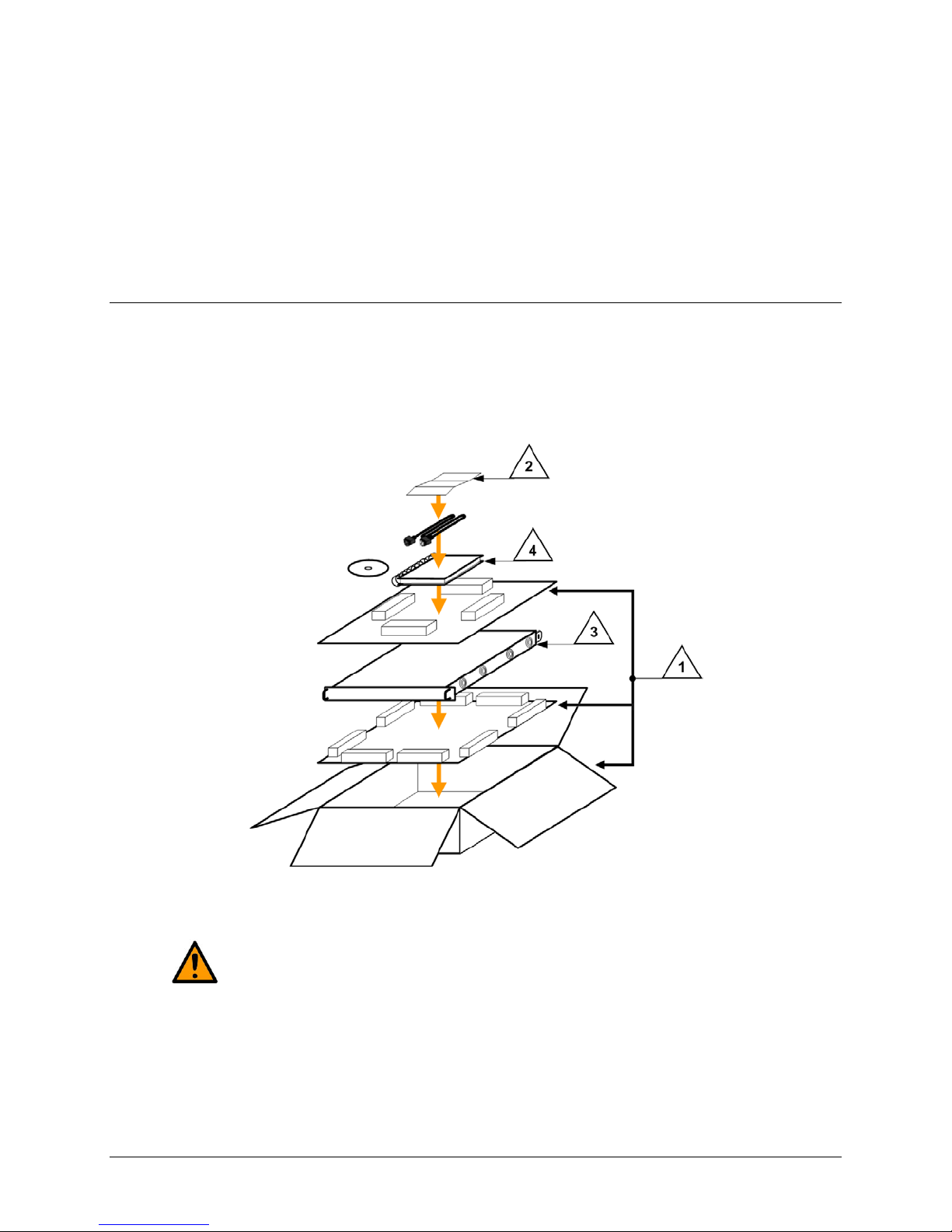
2.1 Unpacking and Inspecting the Shipment
The CDD-56xA/L Satellite Multi-Channel Demodulator, its Installation and Operation Manual, and its
power cord were packaged and shipped in a reusable cardboard carton containing protective foam
spacing.
Figure 2-1. Unpacking and Inspecting the Shipment
This equipment contains parts and assemblies sensitive to damage by Electrostatic
Discharge (ESD). Use ESD precautionary procedures when handling the equipment.
2–1
Page 44

CDD-562AL/564A/L Multi-Channel Dem odulator Revision 0
CAUTION
Installation and Startup MN-CDD562AL564AL
Step Task
1 Keep all shippi ng m aterials for storage or reshipment.
2 Check the packing list to ensure the shipment is complete.
3
4 Read the Installation and Operation Manual carefully to become familiar with operation.
Inspect the equipment for any possible damage incurred during shipment. Contact the carrier
and Comtech EF Data immediately to submit a dam age report if damage is evident.
2.2 Installing the CDD-56xA/L into a rack
For information about custom rack enclosures, contact Comtech EF Data Customer Support during
normal business hours or visit Comtech EF Dat a’s Web site (www.comtechefdata.com/support.asp
The CDD-56xA/L CANNOT have rack slides installed on the sides of the chassis. Cooling fans and
exhaust vents are provided here – air flow must not be impeded.
Comtech EF Data recommends that an alternate method of support is provided within the rack, such as
standard rack shelves (Figure 2-2) or the optional Rear Support Brackets Kit (Figure 2-3). If there is any
doubt, contact Comtech EF Data Customer Support during normal business hours.
PROPER GROUNDING PROTECTION IS REQUIRED. The equipment must be
connected to the protective earth connection at all times. It is therefore imperative that
).
the unit is properly grounded, using the ground stud provided on the unit rear panel,
during installation, configuration, and operation.
PROPER AIR VENTILATION IS REQUIRED. In a rack system where there is high
heat discharge, provide forced-air cooling with top- or bottom-installed fans or blowers.
Make sure there is adequate clearance inside the enclosure, especially at the side for
air ventilation.
Air temperature inside the rack enclosure should never exceed 50°C (122°F).
2–2
Page 45

CDD-562AL/564A/L Multi-Channel Dem odulator Revision 0
Installation and Startup MN-CDD562AL564AL
Figure 2-2. Installation into a Rack Enclosure
Install the CDD-56xA/L in its assigned position in the rack enclosure. Use, as required:
• A standard rack in stallation shelf;
• User-supplied screws to secure the front panel to the rack enclosure threaded front installation
rails;
• Comtech EF Data’s optional KT/6228-2 (4”) or KT/6228-3 (10”) Rear Support Brackets Kit.
2–3
Page 46

CDD-562AL/564A/L Multi-Channel Dem odulator Revision 0
Installation and Startup MN-CDD562AL564AL
2.2.1 Installing the Optional Rear Support Brackets Kit
Figure 2-3. Optional Rear Support Brackets Kit Installation
Detail Description
1 Back of Unit
2 Rack Enclosure Threaded Rear Installation Rail (typical)
Kit / Quantity
Item
KT/6228-2 KT/6228-3
1 2 2 HW/10-32SHLDR Shoulder Screw, #10
2 4 4 HW/10-32FLT Flat Washer, #10
3 2 2 HW/10-32SPLIT Lock Washer, #10
4 2 2 HW/10-32HEXNUT Hex Nut, #10
5 4 4 HW/10-32x1/2RK Bolt, #10, Rear Support Bracket
2 – FP/6138-2 Bracket, Rear Support – 4”
6
– 2 FP/6138-3 Bracket, Rear Support – 10”
Part Number Description
2–4
Page 47

CDD-562AL/564A/L Multi-Channel Dem odulator Revision 0
Installation and Startup MN-CDD562AL564AL
The tools needed to install the KT/6228-2 (4”) or KT/6228-3 (10”) Rear Support Brackets Kit are as
follows:
• A medium Phillips screwdriver
• A 5/32-inch SAE Allen Wrench
• An adjustable Crescent wrench.
To install the kit (Figure 2-3):
Step Task
1
2
3
Use the #10 flat washers, #10 split washers, and #10 hex nuts to secure the #10 shoulder
screws to the unit chassis through the rear rig ht and left side installation slots.
Use the #10 rack bracket bolts to install the rear s upport brackets onto the rack enclosure
threaded rear installation rails.
Install the unit into the rack enclosure. Ensure that the shoulders of the #10 shoulder screws
properly engage into the rear support bracket slots.
2.3 Initial Configuration
There are no internal jumpers to configure, no interface cards to install, and no other options to install.
You set up all configurations via the firmware.
The unit has a default 375 kbps, TPC, QPSK, Rate 3/4 configuration. First, make sure to set up additional
configuration changes through the RJ-11 Console Interface locally.
NOTE: The auto-sensing AC power supply does not require any adjustments. Simply
plug in the supplied line cord, and turn on the switch on the rear panel.
2.4 Connecting External Cables
Once the desired configuration settings have been made, proceed to connect all external cables to the
connectors described in Chapter 3. Should difficulties occur, call Comtech EF Data Customer Support for
assistance.
2–5
Page 48

CDD-562AL/564A/L Multi-Channel Dem odulator Revision 0
Installation and Startup MN-CDD562AL564AL
BLANK PAGE
2–6
Page 49

CDD-562AL/564A/L Multi-Channel Dem odulator Revision 0
Rear Panel Connections MN-CDD562AL564AL
Chapter 3. REAR PANEL
CONNECTOR PINOUTS
3.1 CDD-56xA/L Rear Panels Overview
CDD-564AL Quad Demodulator (L-Band)
CDD-564A Quad Demodulator (IF Band)
CDD-562AL Demodulator (L-Band)
Figure 3-1. CDD-56xA/L Rear Panel Views
Use the rear panel connectors for all external connections between the unit and other equipment. See
Figure 3-1 and Table 3-1.
3–1
Page 50

CDD-562AL/564A/L Multi-Channel Dem odulator Revision 0
(L-Band)
/Function
Name
Rear Panel Connections MN-CDD562AL564AL
3.2 CDD-56xA/L Cable Connecti ons
Table 3-1. Rear Panel External Cable Connections
Section
3.2.1
Section
3.2.2
3.2.3
Service Type
/Function
Rx IF
/RF Input
Service Type
Terrestrial Data
/Ethernet Traffic and M&C
Dedicated Management Port 10/100 Ethernet RJ-45 female
Utility
/Remote Interface for Factory
Test
Utility
/Async Serial Console Port
Connector
Name
Rx 1
Rx 2
Rx 3 N/A
Rx 4 N/A
Connector
10/100 Ethernet RJ-45 female
Remote Control
or
Factory Test
Console RJ-11 female
CDD-562AL
Type N
female
Type N
female
Type for all CDD-56xA/L units
9-pin Type D male
NOT FOR CUSTOMER USE
CDD-564AL
(L-Band)
Type N
female
Type N
female
Type N
female
Type N
female
CDD-564A
(IF Band)
Type BNC
female
Type BNC
female
Type BNC
female
Type BNC
female
CAUTION
The European EMC Directive (EN55022, EN50082-1) requires using properly shielded cables
for DATA I/O. These cables must be double-shielded from end-to-end, ensuring a continuous
ground shield.
3–2
Page 51

CDD-562AL/564A/L Multi-Channel Dem odulator Revision 0
Rear Panel Connections MN-CDD562AL564AL
3.2.1 Rx IF Connections
3.2.1.1 CDD-562AL
CAUTION
DC voltages can be present on the Type N Rx IF connectors, up to a maximum of 18 volts.
and CDD-564AL L-Band Chassis Rx Input
The Rx IF input port connectors on the L-Band demodulators are 50Ω N female types. The return loss on
these ports is typically better than 17 dB.
To connect to a 75Ω system, use an inexpensive N to F type adapter. The adapter is available as an
optional accessory. This setup will cause a slight reduction in return loss. The effect on most systems is
minimal.
The CDD-562AL has two connectors labeled Rx1 and Rx2.
The CDD-564AL has four connectors labeled Rx 1, Rx 2, Rx 3 and Rx 4.
3.2.1.2 CDD-564A 70/140 MHz IF Chassis Rx Input
CAUTION
DC voltages can be present on the BNC Rx IF connectors, up to a maximum of 18 volts.
The Rx IF input port connectors on the 70/140 MHz IF demodulators are BNC female types. The return
loss on these ports is typically better th an 17 dB for both 50Ω and 75Ω systems.
The CDD-564A has four BNC connectors labeled Rx 1, Rx 2, Rx 3 and Rx 4.
3–3
Page 52

CDD-562AL/564A/L Multi-Channel Dem odulator Revision 0
Rear Panel Connections MN-CDD562AL564AL
3.2.2 Terrestrial Data Connections – 10/100 Ethernet (RJ-45)
The 10/100 BaseT Ethernet ports are standard 8-pin RJ-45 modular jacks. One port is labeled TRAFFIC,
and the other port is labeled M&C.
The TRAFFIC port is used for Ethernet traffic.The M&C port is used for management and firmware
updates via Telnet/HTTP/SNMP. The M&C port is available only when the Dedicat ed Management Port
is enabled. The Dedicated Management Port is disab led, by default.
Pin # Function
1 Tx+
2 Tx3 Rx+
4 N/C
5 N/C
6 Rx7 N/C
8 N/C
3–4
Page 53
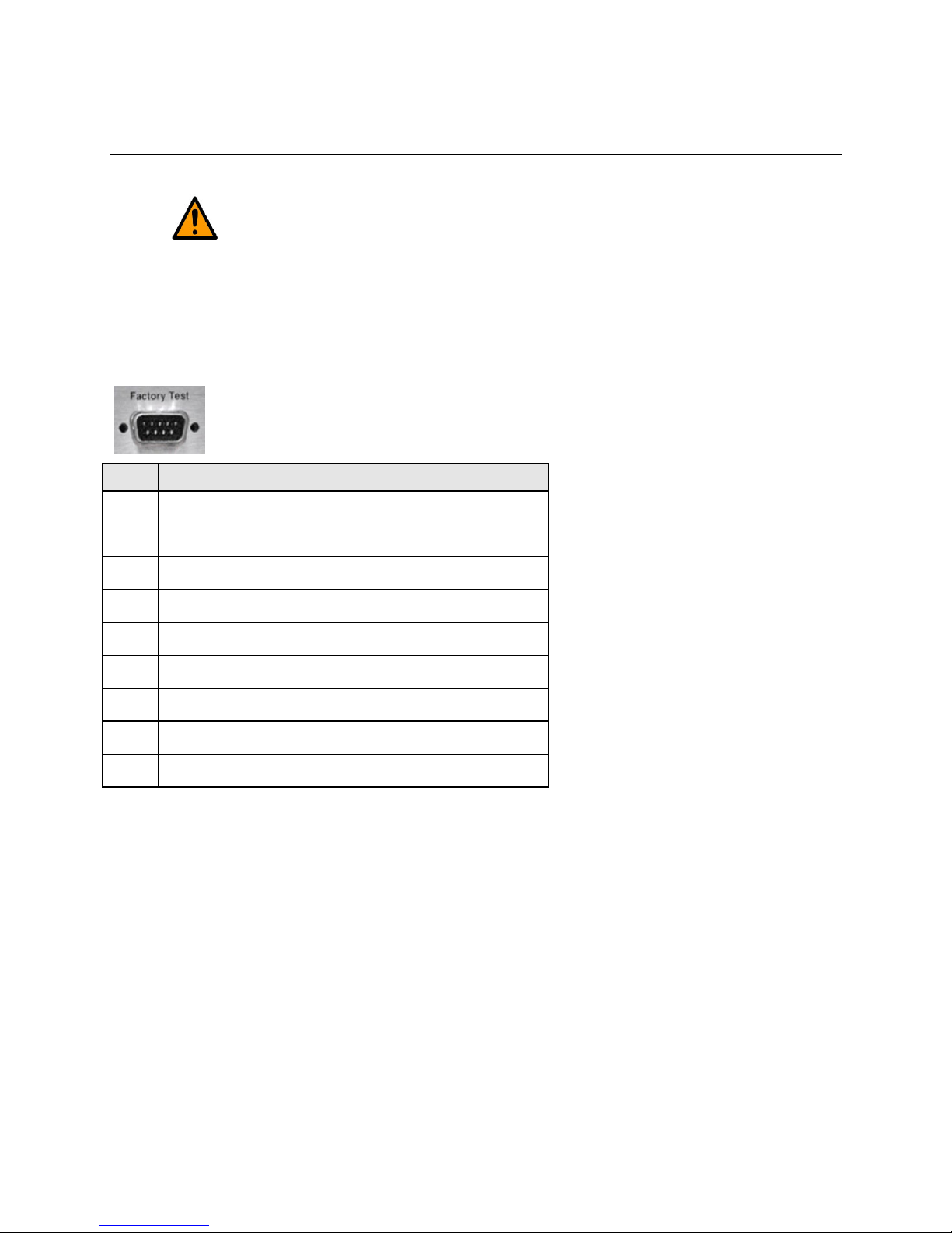
CDD-562AL/564A/L Multi-Channel Dem odulator Revision 0
Pin #
Description
Direction
Rear Panel Connections MN-CDD562AL564AL
3.2.3 Utility Connections
3.2.3.1 Remote C ont r ol (DB-9M)
CAUTION
This connector is not a standard EIA-232 interface. It is not intended for customer use.
It is intended for Factory Test use only. Contact CEFD Customer Support prior to
connecting any equipment to this interface.
The Factory Test interface is a 9-pin Ty pe D male (DB-9M) connector, reserved for use in factory test
applications.
1 Ground -6 Selected Demod RS-422 Rx Data + In
2 EIA-232 Transmit Data (38.4k, 8N1 fixed) Out
7 Selected Demod RS-422 Rx Data - In
3 EIA-232 Receive Data (38.4k, 8N1 fix ed) In
8 Selected Demod RS-422 Tx Clock + Out
4 Selected Demod I-Channel monitor Out
9 Selected Demod RS-422 Tx Clock - Out
5 Selected Demod Q-Channel monitor Out
3–5
Page 54

CDD-562AL/564A/L Multi-Channel Dem odulator Revision 0
Rear Panel Connections MN-CDD562AL564AL
3.2.3.2 Console (RJ-11 Async-Serial Port)
The Console port is a standard 6-pin RJ-11 modular jack. The Async-Serial EIA-232 DCE Console
services the IP Module Command Line Interface (CLI). The supplied adapter cable connects the user PC
to the Console port. A user-supplied terminal emulator program such as HyperTerminal or Tera Term is
used for management of demodulator and IP Module functions.
Pin # Function
1 Ground
2 Rx
3 Tx
4 Ground
5 Not used
6 Not used
3.3 CDD-56xA/L Ground and Power Connections
3.3.1 Chassis Ground Interface
CAUTION
CORRECT GROUNDING PROTECTION IS REQUIRED. The equipment must be
connected to the protective earth connection at all times. It is imperative that the unit is
properly grounded, using the ground stud provided on the unit rear panel, during
installation, configuration, and operation.
Use the #10-32 stud, located adjacent to the power interface, for connecting a common chassis ground
among equipment.
NOTE: The AC power interface provides the safety ground.
3–6
Page 55

CDD-562AL/564A/L Multi-Channel Dem odulator Revision 0
Rear Panel Connections MN-CDD562AL564AL
3.3.2 100V/240V Alternati ng Current (AC) Power Interface (Standard)
3 IEC Three-prong Connector 2 Press-fit Fuse Holder 1 On / Off Switch
Figure 3-2. CDD-56xA/L AC Power Interface
AC Power Specifications
Input Power 106 W maximum, 63 W typical
Input Voltage
Connector Type IEC
Fuse Protection
100 V to 240 V AC, +6%/-10%, autosensing
(total absolute max. range is 90 V to 254 V AC)
Line and neutral fusing
(2X) 5mm x 20mm Slow-blow type fuses:
T2 (2.00 Amp) (100 V or 240 V AC operation)
3.3.2.1 AC Operation – Applying Power
Figure 3-3. Applying AC Power to the CDD-56xA/L
To apply AC power to the CDD-56xA/L (Figure 3-3):
1. Plug the provided AC power cord female end into the unit.
2. Plug the AC power cord male end into the user-supplied power source.
3. Switch the unit ON.
3–7
Page 56

CDD-562AL/564A/L Multi-Channel Dem odulator Revision 0
WARNING
Disconnect the power supply first.
Rear Panel Connections MN-CDD562AL564AL
3.3.2.2 AC Operation – Replacing Fus es
The CDD-56xA/L uses two 5mm x 20mm Slow-blow fuses – one each for line and neutral connections.
The fuses are contained within a fuse h older that is press-fit into the body of the IEC power module
(located on the rear panel, Figure 3-4).
Figure 3-4. Replacing CDD-56xA/L AC Fuses
To replace the fuse(s):
1. Disconnect the power supply.
2. Unseat the fuse holder from the IEC power module.
a. Use the slot to pry the holder outward from the IEC power module.
b. Pull the holder straight out, and then swing the holder away from the module.
3. Remove and replace the T2 (2.00 Amp) fuses as needed.
4. Re-seat the fuse holder in the IEC power module.
CAUTION
For continued operator safety, always replace the fuses with the correct type and rating.
See Table 3-2.
Table 3-2 Correct Fuses
Model Input Power Consumption Fuse
CDD-564A AC 100-240VAC, 50-60HZ, 0.62-0.26A 1A
CDD-564AL AC 100-240VAC, 50-60HZ, 1.24-0.52A 2A
CDD-562AL AC 100-240VAC, 50-60HZ, 0.75-0.31A 1A
CDD-564A DC 43-60VDC, 1.43-1.1A 2A
CDD-564AL DC 43-60VDC, 2.9-2.1A 4A
CDD-562AL DC 43-60VDC, 1.73-1.25A 2.5A
3–8
Page 57

CDD-562AL/564A/L Multi-Channel Dem odulator Revision 0
DC Power Specifications
Rear Panel Connections MN-CDD562AL564AL
3.3.3 48V Direct Current (DC) Power Interface (Optional)
1 Plug-in Power Receptacle
Figure 3-5. CDD-56xA/L DC Power Interface
Input Power 48 W (typical)
106 W (maximum)
Input Voltage 48 V DC nominal
(36 V to 60 V)
Connector Type Corcom PS series
Mating Connector Corcom GA210 or Molex 03-12-1026
Fuse Protection Line and Neutral Fusing
(2X) 5mm x 20mm Slow-blow type fuses:
T4A (4 Amp)
3.3.3.1 DC Operation – Applying Power
Figure 3-6. Applying DC Power to the CDD-56xA/L
To apply DC power to the CDD-56xA/L:
1. Assemble the user-supplied red (+) and black (–) DC power leads and their crimped terminals
into the shell of the module mating connector.
a. Number 18 AWG minimum wires are recommend ed.
b. Note the keyed orientation for the wires.
2. Connect the user-supplied DC power leads to the power source.
3. Plug the connector into the keyed module socket as shown.
3–9
Page 58
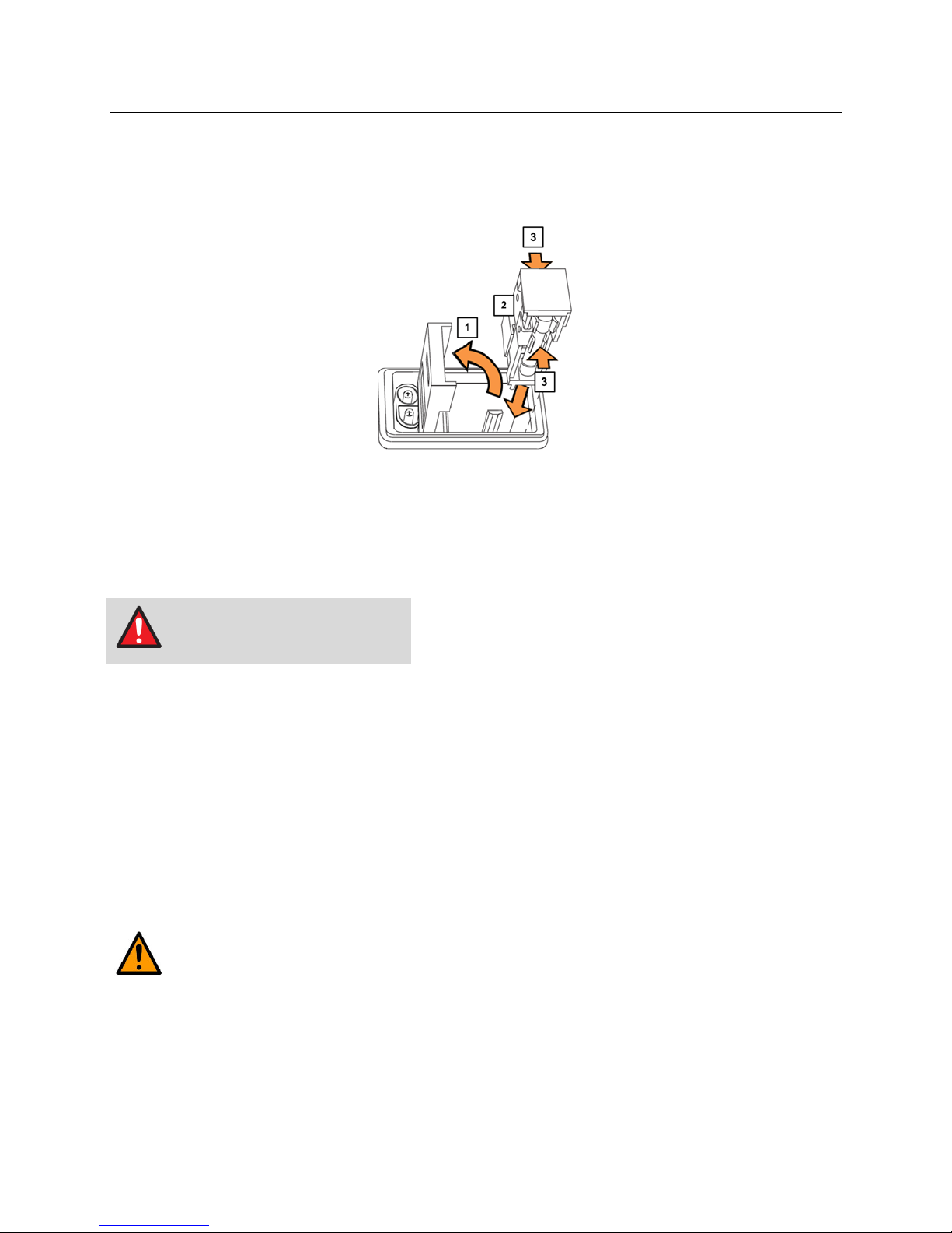
CDD-562AL/564A/L Multi-Channel Dem odulator Revision 0
WARNING
Disconnect the power supply first.
Rear Panel Connections MN-CDD562AL564AL
3.3.3.2 DC Operation – Replacing Fus es
The CDD-56xA/L uses two 5mm x 20mm Slow-blow fuses – one each for line and neutral connections.
The fuses are contained within a fuse h older that is press-fit into the body of the DC power module
(located on the rear panel, Figure 3-7).
1 Hinged Flap
2 Press-fit Fuse Holder
3 Fuse (2X)
Figure 3-7. Replacing CDD-56xA/L DC Fuses
To replace the fuse(s):
1. Disconnect the power supply.
2. Use a flat-bladed screwdriver to pry open the slot and swing back the hinged flap.
3. Extract the press-fit fuse holder:
a. Using the screwdriver, disengage the fuse holder outward from the DC power module.
b. Using your fingers, pull the holder straight out of the module.
4. Remove and replace the T4A (4 Amp) fuses as needed.
5. Re-seat the fuse holder into the DC power module, and close the protective flap.
CAUTION
For continued operator safety, always replace the fuses with the correct type and rating.
See Table 3-2
3–10
Page 59

CDD-562AL/564A/L Multi-Channel Dem odulator Revision 0
IP Module Ethernet Interface MN-CDD562AL564AL
Chapter 4. IP MOD U LE ETHER N ET
INTERFACE
4.1 Introduction
The CDD-56xA/L Satellite Demodulator’s integral IP Module Ethernet Interface is intended for closed
network Single Channel Per Carrier (SCPC) links. It concentrates traffic from two or four independent
demodulators into a single Ethernet port, making it ideal for networked VSAT applications. The
CDD-56xA/L can also be used in a Vipersat satellite bandwidth management system.
NOTE: For information specific to CDD-56xA/L IP Module operation when used in a
Vipersat system, please see Comtech EF Data publication MN/22137 – Vipersat CDD-
56X Series Satellite Network Demodulator Router User Guide.
4.1.1 Standard Features
• Two 10/100BaseT Ethernet Interfaces (RJ-45)
• Powerful network management:
o SNMP with public and private MIB
o Telnet interface for remote product M & C
o Web Server interface for complete product management
o Console Port interface for local network management
• Remote software/fir mware upgrade via FTP
• Configuration backup and restore via FTP
• Event Logging to capture all IP Module activity
• Detailed Statistics of IP traffic
• IGMP support for Multicast
• Static IP routing for unicast and multicast
4–1
Page 60

CDD-562AL/564A/L Multi-Channel Dem odulator Revision 0
IP Module Ethernet Interface MN-CDD562AL564AL
• Symmetric and/or asymmetric operation for maximum bandwidth effici ency
• Point-to-Point or Point-to-Multipoint configuration
• Interoperable with these Comtech EF Data modems:
o CDM-570/L-IP
o CDM-570A/L-IP
4.1.2 10/100 BaseT Ethernet Interfaces
The two 10/100BaseT Ethernet Interfaces are used for routing IP traffic received over the satellite to
another device on the local LAN, and for monitor and control purposes.
4.1.3 Powerful Network Management
Local or remote management of all demodulator and IP Module functions is available via SNMP, Telnet,
or HTTP. The demodulator may be configured, operated and monitored using any of the following
methods:
User Interface Connection
SNMP
Telnet
Serial Command Line
Interface (CLI)
Web Server
Local or remote – Ethernet via 10/100
BaseT Traffic/M&C interface
Local or remote – Ethernet via 10/100
BaseT Traffic/M&C interface
Local – Serial RS-232 via Console Port ALL ALL
Local or remote – Ethernet via 10/100
BaseT Traffic/M&C interface
Demod
Functions
ALL ALL
ALL ALL
ALL ALL
IP MODULE
Functions
4.1.4 Remote Firmware Update via FTP
See Chapter 5, Updating Firmware.
The CDD-56xA/L Multi-Channel Demodulator uses flash memory technology internally. Firmware
update archive files may be downloaded from the Internet to a user PC (from Comtech EF Data’s
website), or obtained through Comtech EF Data Customer Support via e-mail or on CD by standard mail
delivery.
Once acquired from Comtech EF Data, new firmware can be uploaded from the user PC by File Transfer
Protocol (FTP) without opening the unit or having to be in the same physical location.
4.1.5 Configuration Backup and Restore via FTP
All demodulator configuration parameters are stored in a simple text file. The parameter file can easily be
retrieved locally or remotely by FTP. The file can then be used to quickly configure a replacement unit if
needed.
4–2
Page 61

CDD-562AL/564A/L Multi-Channel Dem odulator Revision 0
Supported Ethernet Headers
IP Module Ethernet Interface MN-CDD562AL564AL
4.1.6 Event Logging to Capture All Demodulator Activity
All activity can be stored into an easy-to-read Event Log. This file also can be retrieved locally or
remotely by FTP.
4.1.7 Detailed Statistics of IP Traffic
IP traffic statistics are continuously updated and allow detailed performance analysis or can be used to
identify traffic problems. The statistics are available through the Serial Console locally, or can be
gathered remotely by SNMP, Telnet, or HTTP.
4.1.8 IGMP Support for Multicast
IGMP is a standard feature in the demodulat or. If enabled as an IGMP client, it responds to IGMP queries
for the configured multicast routes. If enabled as an IGMP server, it generates IGMP queries and
transmits multicast traffic per IGMP clien ts’ request. If there are no active IGMP client s on the LAN, it
will stop forwarding the multicast traffic (received from the satellite) to the LAN.
4.1.9 Static IP Routing for Unicast and Mul ticast
Up to 256 static routes can be entered into the demodulator to direct IP traffic to another device on the
local LAN.
4.2 Demodulator Features
See Chapter 6, Fast Activation Procedure.
Additional features can be added quickly on site to the CDD-56xA/L by entering FAST Access Codes
purchased from Comtech EF Data. FAST-accessible options include:
• IP Header Decompression
• Payload Decompression (future)
4.2.1 3xDES Decryption with Ability to Change Keys (future)
The EN version supports 3xDES-128 (using NIST certified 3x core) decryption for the highest-level
security. For link encryption, each unit supports eight decryption keys.
4.2.2 IP Header Decompression
Header Decompression also is an optional feature of the demodulator. The demodulator supports Header
Decompression for the following Ethernet and Layer 3 & 4 Headers:
Ethernet 2.0
4–3
Page 62

CDD-562AL/564A/L Multi-Channel Dem odulator Revision 0
Supported Layer 3&4 Headers
IP Module Ethernet Interface MN-CDD562AL564AL
Ethernet 2.0 + VLAN-tag
Ethernet 2.0 + MPLS
802.3-raw
802.3-raw + VLAN-tag
802.3 + 802.2
802.3 + 802.2 + VLAN-tag
802.3 + 802.2 + SNAP
802.3 + 802.2 + SNAP + VLAN-tag
802.3 + 802.2 + SNAP + MPLS
IP
TCP
UDP
RTP (Codec Independent)
Header Compression reduces the required VoIP bandwidth by 60 percent. Example: A G.729a voice
codec, operating at 8 kbps, will occupy 32 kbps once encapsulated into IP framing on a LAN. Using
IP/UDP/RTP Header Compression, the same traffic only needs 10.8 kbps total WAN satellite bandwid th
to cross the link. A total maximum of 64 simultaneous VoIP calls can be compressed. Norm al Web/HTTP
traffic can be reduced an additional 10% via IP/TCP header compression.
4.2.2.1 Header Decompression Configuration
Header Decompression requires one configuration change. Make sure the Header Compression and
Decompression feature is enabled on both the sending and receiving IP modem and demodulator.
Packets with a Header Decompression header are identified automatically for decompression.
You might want to change only one configuration parameter: the Header Decompression Refresh Rate.
This rate is how many decompressed header packets are sen t before a single, full header packet is sent.
Sometimes, compressed header traffic can be lost during poor satellite link conditions. Sending a full
header packet allows the traffic stream to return. You can i ncrease the Refresh Rate for poor satellite link
conditions, or decrease the Refresh Rate to reduce overhead.
4.2.3 Payload Decompression (future)
Traffic optimization through Payload Decompression is another optional feature of the demodulator.
• FAST feature to upgrade
• Compression algorithm applied to all data (HDLC header excluded) on the transmit side
• Compression algorithm not applied to RTP streams because this traffic is already compressed and
would only increase the satellite bandwidth if compressed again.
4–4
Page 63
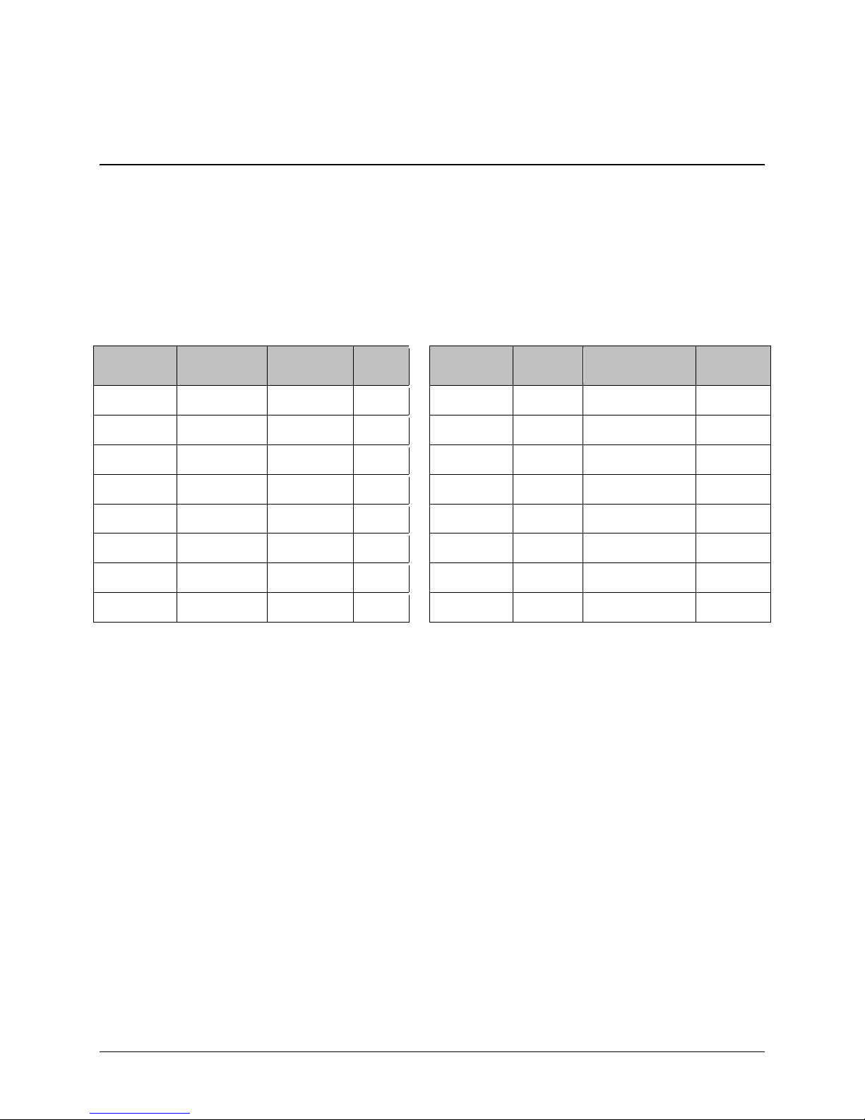
CDD-562AL/564A/L Multi-Channel Dem odulator Revision 0
IP Module Ethernet Interface MN-CDD562AL564AL
• Additional statistics added to the compression statistics menu to give feedback on the
compression efficiency achieved.
4.2.3.1 ALDC vs LZS Com pres si on Comparison
These numbers have been generated using an internally created test program. This program takes the
target benchmark files and splits the files into payload size chunks and compresses each chunk in a
separate invocation of the compression algorithm. This is important to note because most compression
algorithms are applied to the entire file dat a set as a single invocation of the compression algorithm,
which is easier for other types of compression algorithms (LZS, GZIP in specific). This, of course, does
not apply to streamed packet data across an IP network (e.g., FTP transfer).
Algorithm
ALDC 1472 Calgary 1.76 LZS 1472 Calgary 1.66
ALDC 1000 Calgary 1.76 LZS 1000 Calgary 1.66
ALDC 500 Calgary 1.77 LZS 500 Calgary 1.68
ALDC 100 Calgary 2.09 LZS 100 Calgary 1.97
ALDC 1472 Canterbury 1.71 LZS 1472 Canterbury 1.61
ALDC 1000 Canterbury 1.72 LZS 1000 Canterbury 1.62
ALDC 500 Canterbury 1.74 LZS 500 Canterbury 1.63
ALDC 100 Canterbury 2.04 LZS 100 Canterbury 1.91
Payload
size
File Set Ratio
Algorithm
Payload
size
File Set Ratio
4–5
Page 64

CDD-562AL/564A/L Multi-Channel Dem odulator Revision 0
RFC
Protocol
IP Module Ethernet Interface MN-CDD562AL564AL
4.3 IP Module Specifications
4.3.1 Supported RFCs and Protocols
RFC 768 User Datagram Protocol RFC 791 Internet Protocol
RFC 792 Internet Control Message Protocol RFC 793 Transmission Control Protocol
RFC 826 An Ethernet Address Resolution Protocol RFC 856 Telnet Binary Tr ansmission
RFC 862 Echo Protocol
RFC 959 File Transfer Protocol
RFC 1213 Management Information Base for Network
Management of TCP/IP-based internet: MI B-II
RFC 2045 Multipurpose Internet Mail Extensions (MIME)
RFC 2578 Structure of Management Informati on Version 2
(SMIv2)
RFC 2598 An Expedited Forwarding PHB
RFC 3416 Version 2 of the Protocol Operations for t he
Simple Network Management Protocol (SNMP)
RFC 894 A Standard for the Transmission
of IP Datagrams over Ethernet Networks
RFC 1112 Host Extensions for IP
Multicasting
RFC 1812 Requirements for IP Version 4
Routers
RFC 2236 Internet Group Management
Protocol, Version 2
RFC 2475 An Architecture for
Differentiated Services
RFC 2616 Hypertext Transfer Protocol –
HTTP/1.1
RFC 3412 Message Processing and
Dispatching for the Simple Network
Management Protocol (SNMP)
RFC 3418 Management Information Base
(MIB) for the Simple Network Management
Protocol (SNMP)
4.3.2 CDD562AL/564AL Compatibility
The CDD-56xA/L is compatible with other Comtech EF Data IP modems (referred to hereafter as CDMIP), provided the modems have similar operating modes and IP options.
CDD-564L
IP FW Version
Version 1.3.1 or later
Version 1.3.1 or later
IP Modem / IP FW Version
CDM-570/570L
Version 1.4.0 or later
CDM-570A/570L
Version 1.3.1 or later
Comtech EF Data
Comments
Select the correct compatibility mode wh en
receiving traffic from the CDM-570
4–6
Page 65

CDD-562AL/564A/L Multi-Channel Dem odulator Revision 0
HDLC Address Mode
IP Module Ethernet Interface MN-CDD562AL564AL
4.4 Typical IP Module Operational Setups
The CDD-56xA/L has several modes of operation. The typical setup examples that follow serve as a
means to determine the best mode of operation for the appropriate network topology and Ethernet traffic
environment.
4.4.1 IP Module Working Modes
Typical CDM-IP modems support two Working Modes: Managed Switch Mode (formerly
easyConnect) and Router Mode; however, the demodulator only supports Router Mode, so the CDM-IP
modem that is transmitting to demodulator must be in Router Mode. Non-IP traffic is not supported in
Router Mode.
Router Mode supports three HDLC Addressing Modes: Point-to-Point, Small Network, and Large
Network. Separate HDLC Modes allow the user to minimize the HDLC overhead transmitted over the
satellite based on the size of their network.
In Router/Point-to-Point Mode, no HDLC address i s transmitted, Router/Small Network transmits 1 byte,
and Router/Large Network transmits 2 bytes as part of HDLC header for each packet.
In the sections that follow, the functionality of these modes is described in further detail, in order to
optimize the Comtech EF Data IP modems in the network, based upon Network Topology and Ethernet
Traffic requirements.
The demodulator only supports Router Mode, so the CDM-IP modem that is transmitting to demodulator
must be in Router Mode.
The HDLC Address Mode of the Comtech EF Dat a IP modems must be identical to pass traf f ic between
the TX modems and the demodulator.
Changing the HDLC Address Mode of the demodulator requires the IP Module to be rebooted. Before the
user can select a different mode, the demodulator will notify the user that changing the mode will require
a reboot.
Working Mode
Router Mode
Point-to-Point
Router Mode
Small Network
Router Mode
Large Network
Point-to-Point only
Both sites on different LAN subnet
Point-to-Point or Point-to-Multipoint (up to 254 sites)
All sites on different LAN subnet
Point-to-Point or Point-to-Multipoint (up to 32766 sit es)
All sites on different LAN subnet
Network Topology Ethernet Traffic
IP v4 only
IP v4 only
IP v4 only
Feature Support - The demodulator also has several standard and optional features to further optimize
security, performance and efficiency.
Standard Features Additional Notes
HDLC Address Mode Point-to-Point, Small Network, or Large Network
Access Lists 4 Clients by IP or IP Subnet
4–7
Page 66

CDD-562AL/564A/L Multi-Channel Dem odulator Revision 0
Optional Features
Additional Notes
IP Module Ethernet Interface MN-CDD562AL564AL
Standard Features Additional Notes
Multicast RX all or specific Multicast streams
IGMP IGMPv1, IGMPv2
Upgrade by FTP
By local LAN or remotely through satellite (requi res a two way connection to
demodulator)
Header Decompression Must be enabled if any TX modem stream has Header Compression enabled.
Payload
Must be enabled if any TX modem stream has Payload Compression enabled.
Decompression (future)
3xDES Decryption
(future) (EN version
Must be enabled if any TX modem stream has 3xDES Encryption enabled.
Up to 8 Decrypt Keys or random
only)
4–8
Page 67

CDD-562AL/564A/L Multi-Channel Dem odulator Revision 0
IP Module Ethernet Interface MN-CDD562AL564AL
4.4.1.1 Router Working Mode with DVB Overlay
Figure 4-1 shows an example setup using the CDD-562L L-Band Satellite Dual Demodulator at a Hub
site to receive two separate return chan nels.
• The CDD-562L and all CDM-IP modems are in Point-to-Point Mode.
• Each remote site has a CDM-IP modem with a default static route.
• The CDD-562L has a default static route directing traffic to the hub router.
• The hub router would have routes defined for each remote network that would be directed to
the DVB Encapsulator.
Figure 4-1. (CDD-562L) Router Mode Point-to-Point Diagram
Figure 4-2 shows an example setup using the CDD-564 (70/140 MHz) or CDD-564L (L-Band) Satellite
Quad Demodulator at a Hub site to receive t hree separate return channels.
• The demodulator and all CDM-IP modems are in Point-to-Point Mode.
• Each remote site has a CDM-IP modem with a defaul t static route.
• The demodulator has a default static route directing traffic to the hub router.
4–9
Page 68

CDD-562AL/564A/L Multi-Channel Dem odulator Revision 0
IP Module Ethernet Interface MN-CDD562AL564AL
• The hub router would have routes defined for each remote network that would be directed to the
DVB Encapsulator.
Figure 4-2. (CDD-564/564L) Point-to-Point Router Working Mode Diagram
4–10
Page 69

CDD-562AL/564A/L Multi-Channel Dem odulator Revision 0
IP Module Ethernet Interface MN-CDD562AL564AL
4.4.1.2 Router Working Mode – Point-to-Multipoint
Figure 4-3 shows a “Star Network” Point-to-Multipoint Configuration, where the Hub CDM-IP modem is
transmitting a common TDM carrier to two remote sites with CDM-IP modems. In turn, the Remote
CDM-IP is transmitting a link back to the Hub that is received by the CDD-562L L-Band Satellite Dual
Demodulator. (TX C is shown, but is not required.)
Figure 4-3. (CDD-562L) Point-to-Multipoint Router Working Mode Diagram
4–11
Page 70

CDD-562AL/564A/L Multi-Channel Dem odulator Revision 0
IP Module Ethernet Interface MN-CDD562AL564AL
Figure 4-4 shows a “Star Network” Point-to-Multipoint Configuration where the Hub CDM-IP modem is
transmitting a common TDM carrier to three remote sites with CDM-IP modems. In turn, the Remote
CDM-IP is transmitting a link back to the Hub that is received by the CDD-564 (70/140 MHz) or CDD564L (L-Band) Satellite Quad Demodulator.
Figure 4-4. (CDD-564/564L) Point-to-Multipoint Router Working Mode Diagram
Since this is a Point-to-Multipoint configuration, HDLC addressing is used so that the traffic not intended
for a particular destination can be filtered (Small or Large HDLC Mode). For unicast traffic, it is best to
associate a unique HDLC address for each site in the network. In this case:
• The Hub Site is HDLC 0x01
• CDM-IP Remote ‘A’ is HDLC 0x02
• CDM-IP Remote ‘B’ is 0x03
• CDM-IP Remote ‘C’ is 0x04.
• Each CDM-IP modem would select the HDLC address associated with its site as an Rx HDLC
Address. Therefore:
o Both the Hub CDM-IP modem and CDD-564L would have 0x01 as the first RX HDLC
Address
4–12
Page 71

CDD-562AL/564A/L Multi-Channel Dem odulator Revision 0
IP Module Ethernet Interface MN-CDD562AL564AL
o CDM-IP Remote ‘A’ would have 0x02
o CDM-IP Remote ‘B’ would have 0x03
o CDM-IP Remote ‘C’ would have 0x04.
The remote CDM-IP modems only need a single default route to is directed to the Hub HDLC, 0x01. All
of the traffic is managed by the static route entries in the hub CDM-IP and demodulator. The demodulator
has a default route to the router for Internet acce ss. It also has specific routes for the remote networks
which are directed to the Hub CDM-IP. The Hub CDM-IP also has specific routes for the remot e
networks with the HDLC address associated with each site.
4–13
Page 72

CDD-562AL/564A/L Multi-Channel Dem odulator Revision 0
IP Module Ethernet Interface MN-CDD562AL564AL
BLANK PAGE
4–14
Page 73

CDD-562AL/564A/L Multi-Channel Dem odulator Revision 0
Updating Firmware MN-CDD562AL564A/L
Chapter 5. UPDATING FIRMWARE
5.1 Upda ting Firmware via the Internet
NOTE: To ensure optimal performance, it is important to operate the CDD-56xA/L with
its latest available firmware.
The CDD-56xA/L Multi-Channel Demodulator eliminates the need for updating firmware by physically
replacing EPROMs. Instead, the demodulator uses ‘Flash memory’ technology internally. This makes the
firmware update process very simple. Firmware update archive files may be downloaded from the
Internet (from Comtech EF Data’s website) , or obtained through Comtech EF Data Customer Support via
e-mail or on CD by standard mail delivery.
The complete firmware update process is as follows:
• New firmware can be downloaded from Comtech EF Data’s website to a user-supplied PC.
• Transfer the fir mware update file, via File Transfer Protocol (FTP) upload, from the user PC to
the CDD-56xA/L.
• Perform the update, without opening the CDD-56xA/L, using the rear panel interface M&C
connections:
• The 10/100 BaseT Ethernet port connects to the Ethernet port of the user PC for user access to
SNMP/Telnet/HTTP operations.
Note:
If Dedicated Management is disabled, then you must use the Traffic port for the upgrade process.
If Dedicated Management is enabled, then you must use the M&C port for the upgrade process.
• The Console port connects to an available serial port for user access to the IP Module Command
Line Interface (CLI) operations.
5–1
Page 74
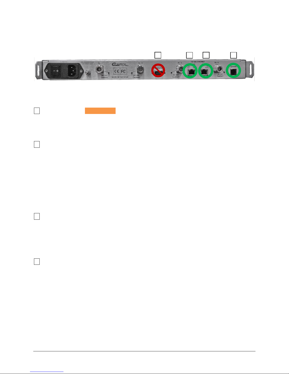
CDD-562AL/564A/L Multi-Channel Dem odulator Revision 0
1 2 4
3
Updating Firmware MN-CDD562AL564A/L
See Figure 5-1. A summary of using the rear panel data interfaces with the CDD-56xAL firmware update
process follows the figure.
Figure 5-1. CDD-564A/L Rear Panel Connections to User PC
Table 5-1. Rear Panel Connections to User PC
1 Factory Test DO NOT USE
• This DB 9M (Type D 9 pin male) connector is not a standard EIA-232 interface. DO NOT USE.
• This is for Factory Test use only, and is not intended for customer use. Contact CEFD Product
Support before you try to connect any equipment to this interface.
2 10/100 Ethernet
• BaseT Ethernet port, RJ-45 8-pin modular jack
• Cable:
o CAT5, user-supplied to an available Ethernet port, via hub or switch or direct connection
• Uses:
o Ethernet traffic
o Management of IP Module functions via SNMP/Telnet/ HTTP
o Updating IP Module firmware
3 10/100 M&C Ethernet
• Cable:
o CAT5, user-supplied to an available Ethernet port, via hub or switch or direct connection
• Uses:
o Used when Dedicated Management Port is enabled
4 Console
• Async-Serial EIA-232 DCE port, RJ-11 6-pin modular jack
• Cable:
o Use the provided adapter cable to connect to an available 9-pin serial port.
• Software:
o A user-supplied terminal emulator program such as HyperTerminal or Tera Term is used
for management of demodulator and IP Module functions.
• Uses:
o IP Module Command Line Interface (CLI)
5–2
Page 75
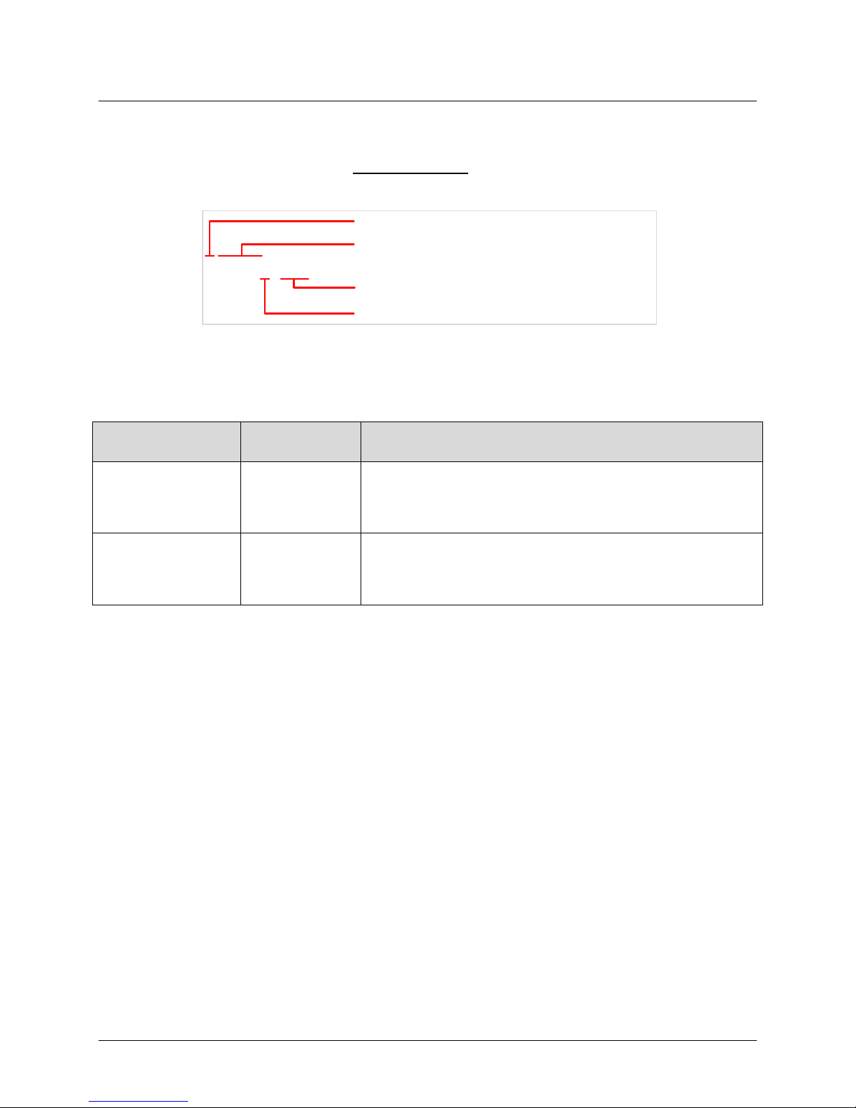
CDD-562AL/564A/L Multi-Channel Dem odulator Revision 0
Filename
F0020894–_V131
FW release version, example: V131 is Version 1.3.1
Revision letter or letters, a hyphen – means initial release
Firmware number, 4 to 7 digits
Product prefix, F or FW means firmware
Updating Firmware MN-CDD562AL564A/L
5.2 About Firmware Files, Naming, Vers ions and Formats
All CEFD products are shipped with the latest released firmware version. This example naming schematic
shows the firmware download hyperlink F0020894X_V###
means the release version.
The CDD-56xA/L is available with 3xDES decryption, optionally.
The firmware updates listed in Table 5-2 are available from Comtech EF Data.
Table 5-2. Firmware Files, Naming and Versions
, where X means the revision letter, and ###
Web Hyperlink
F00208094X_V### FW-0020894X
N/A Contact CEFD
EXE/ZIP
Contains Image File (* means the revision letter)
FW-0020894*.bin – Ver. 1.3.1 (and earlier)
• With HDLC Encapsulation
• Without 3xDES Decryption option
FW-0020895*.bin – Ver. 1.3.1 (and earlier)
• With HDLC Enca psulation
• With 3xDES Decryption option
Comtech EF Data’s website organizes firmware update files by product type and model/optional
configuration.
The firmware download files are availab le from Comtech EF Data in two archive file formats: *.exe (self
extracting) and *.zip (compressed). Some firewalls will not allow downloading of *.exe files. In this case,
download the *.zip file instead. If applicable, one version earlier than the latest release is available f or
download also.
For additional help with compressed file types, refer to the help files provided with the file archiving
programs. Supported programs include:
• PKZIP for Windows
• WinZip
• ZipCentral
The program “PKZIP for DOS” is not supported.
To learn how to verify the correct firmware number, see Section 5.3.1.
5–3
Page 76

CDD-562AL/564A/L Multi-Channel Dem odulator Revision 0
Updating Firmware MN-CDD562AL564A/L
5.3 Ethernet FTP Upload Procedure
5.3.1 Getting Started: Preparing for the Firmware Download
1. Connect the user PC to the CD D-564A /L 10/100 Ethernet port either via a hub or a swit ch, or
with a direct Ethernet cable connection. See Figure 5-1.
2. Connect the CDD-564A/L Console port to a serial port on the user PC using an adapter cable.
Do not use the Factory Test port. See Figure 5-1.
3. Identif y and make a note of the product, its firmware number and version number. These are
necessary for the download process.
4. Use one of these methods to see the current product M&C version and/or firmware number:
a. Using the 10/100 Ethernet port, via HTTP and the IP Module Web Server Interface:
a. Click the Maint (Maintenance) tab.
b. Select the Unit Info hyperlink.
b. Using the 10/100 Ethernet port, via Telnet and the IP Module Command Lin e Interface
(CLI):
a. On the main page, type O for Operations and Maintenance.
b. Type I for Unit Information.
5. Create a temporary folder or subdirectory on the user P C for the firmware archive download. Any
valid, writable drive letter can be used. Use one of these methods:
Use the Windows Desktop to create and rename the temporary folder:
a. Right-Click anywhere on the Windows Desktop to open the popup submenu
b. Select New > Folder to create the temporary folder on the desktop
c. Right-Click on the new folder
d. Select Rename from the popup submenu
e. Rename this folder to temp, or another convenient name
Use Windows Explorer to create and rename the temporary folder:
a. Select File > New > Folder to create a temporary folder in the active folder.
b. Right-click the new folder
c. Rename this folder to temp, or another convenient name
Use Windows Command-line to create the temporary folder:
a. On the Windows taskbar, click Start
b. Click Run...
c. In the Run window, click Browse
d. In the Browse window, click Create New Folder or New Folder
e. Right-click the new folder
f. Rename this folder to temp, or another convenient name
5–4
Page 77

CDD-562AL/564A/L Multi-Channel Dem odulator Revision 0
Updating Firmware MN-CDD562AL564A/L
Alternately:
a. Click Start
b. Select All Programs > Accessories > Command Prompt
c. At the Command-line prompt c:\>, type mkdir temp or md temp
The command mkdir or md means make directory.
d. Click OK
Depending on Windows OS versions prior to Windows 95:
a. On the Main Menu, click MS-DOS Prompt
b. Open a Command-line window:
a. For Windows 95 or Windows 98, type command and press Enter.
b. For any Windows OS versions later than Windows 98, type cmd or command,
and press Enter.
6. Make sure the new folder exists and is ready for the firmware f il e download.
5–5
Page 78

CDD-562AL/564A/L Multi-Channel Dem odulator Revision 0
Updating Firmware MN-CDD562AL564A/L
5.3.2 Downloading and E xtracting the Firmware Update
1. Download the correct firmware archive file to the user PC temporary folder.
a. Go to www.comtechefdata.com
.
b. Go to Home | Support | Software Downloads | Flash & Software Update Files
c. On the Flash & Software Update Files page, click Satellite Modems
d. Click the applicable product hyperlink.
e. Refer to Table 5-2 for information about the firmware download hyperlinks, archive files
and download image files.
f. Click the correct firmware EXE or ZIP download hyperlink (without 3xDES), or contact
CEFD Product Support to get the firmware with 3xDES.
g. Download the archive file to the temporary folder. The File Download window prompts
you to select Open or Save:
a. Click Open to allow the user-supplied utility program to control the file extraction
process
1. Make sure to extract the firmware files to the temporary folder created
earlier
b. Click Save to open the Save As window
1. Make sure to select the archive *.exe or *.zip file and Save it to the
temporary folder created earlier
c. Otherwise, click Cancel to quit the file download process
2. If necessary, extract the firmwa re files from the downloaded *.exe or *.zip archive file. Extract the
firmware files from the archive file with the user-supplied utility program. Extract a minimum of
three files.
In these file names, an asterisk * is a substitute for the revision letter of the image file:
• Without 3xDES:
a. FW-0020894*.bin (Ver. 1.3.1 and earlier)
b. CDD 56xA/L X.X.X Release Notes.pdf (or a variation of this filename)
c. CDD 56xA/L X.X.X Upgrade (or a variation of this filename) – Instal l ation notes
• With 3xDES:
a. FW-0020895*.bin (Ver. 1.3.1 and earlier)
b. CDD 56xA/L X.X.X Release Notes.pdf (or a variation of this filename)
c. CDD 56xA/L X.X.X Upgrade (or a variation of this filename) – Installation notes
3. Make sure the firmware files were extracted correctly to the temporary folder. Use one of these
methods to see the temporary folder’s contents.
• From the Windows Desktop:
a. Double-click the temporary folder that was saved to the Win dows Desktop
b. Or, use Windows Explorer to find the temporary folder
i. Double-click the temporary folder
5–6
Page 79

CDD-562AL/564A/L Multi-Channel Dem odulator Revision 0
Updating Firmware MN-CDD562AL564A/L
c. Or, use the Browse window to find the temporary folder
i. Click Start > Run… > Browse
ii. Double-cl ick the temporary folder
• Using the Command-line:
a. At the Command-line prompt, type cd c:\temp to change to the temporary dire ct ory
created earlier
b. Type dir to see a list of the files that were extracted to the temporary directory
5–7
Page 80

CDD-562AL/564A/L Multi-Channel Dem odulator Revision 0
ftp_upgrade.doc
Updating Firmware MN-CDD562AL564A/L
5.3.3 Bulk F irmware FTP Upload Procedure
NOTE: Read the
included in the *.zip file.
1. Make sure the firmware update has been downloaded to the user PC and is available in the
temporary folder.
2. Make sure the user PC is connected to the CDD-56xA/L 10/100 Ethernet port via a hub, or a
switch, or with a direct Ethernet cable connect i on.
3. Make sure the CDD-56xA/L Console port is connected to a serial port on the user PC with an
adapter cable.
a. Make sure the Remote Control port is not used for this connection.
4. Make sure that the connection and communication between the u ser PC and the CDD-56xA/L is
correct.
a. Find the Management IP Address:
b. Using serial Console CLI:
a. Go to Interface Config | Ethernet Interface
c. Use Command-line to send a ping command to the modem:
a. In Windows:
1. Click Start on the Windows toolbar
2. Click Run...
Or, use Command-line Prompt or Command Prompt in the Start menu
b. For Win95 or Win98: type command and press Enter
c. For WinNT, Win2K or WinXP type cmd and press Enter
d. Type ping xxx.xxx.xxx.xxx at the Command-line prompt, where xxx.xxx.xxx.xxx
is the IP address for the CDD-56xA/L
e. Press Enter
d. Examine the results to make sure the modem is connected and communicating correct ly
5. Use Comm and-line to start an FTP session with the CDD-56xA/L:
a. Type ftp xxx.xxx.xxx.xxx, where xxx.xxx.xxx.xxx is the IP A ddres s for the unit
b. Enter the Admin User Name and Password to finish the login
c. To set the binary transfer mode, type bin and press Enter
d. Type prompt and press Enter
e. To help the file transfer process, type hash and press Enter
6. Upload the files from the temporary folder on the user PC:
a. To start the file transfers, type put FW-0000###*.bin, where 0000### is the firmware
number, and * is the firmware revision letter
b. Press Enter
5–8
Page 81

CDD-562AL/564A/L Multi-Channel Dem odulator Revision 0
Updating Firmware MN-CDD562AL564A/L
The process runs through several blocks. This c an take several minutes. After the firmware
update image file is uploaded, it is written t o flash memory.
7. Change the boot image selection:
By default, the demodulator boots with the version th at has the latest date (Boot to – Latest).
You can set the Boot to parameter to cause the demodulator to boot up using Image #1 or
Image #2.
After you change the Boot to parameter , you must reset (reboot) the unit from the serial
console, the Web Server interface or the CLI/ T elnet interface.
After this reset, the firmware upgrade select i on is active.
a. To reset from the Web Server Interface:
a. Go to the Maint | Reboot page
b. Click Yes, Reboot
b. To reset from the CLI/Telnet Main Menu:
a. Type O for the Operations and Maintenance
b. Type R for Reset
The firmware update process is finished. The CDD-56xA/L is now operating with its latest firmware.
5–9
Page 82

CDD-562AL/564A/L Multi-Channel Dem odulator Revision 0
Updating Firmware MN-CDD562AL564A/L
BLANK PAGE
5–10
Page 83

CDD-562AL/564A/L Multi-Channel Dem odulator Revision 0
FAST Activation Procedure MN-CDD562AL564AL
Chapter 6. FAST ACTIVATION
PROCEDURE
6.1 FAST System Overview
The CDD-56xA/L Multi-Channel Demodulator incorporates a number of optional features. In order to
permit a lower initial cost, the unit may be purchased with only the desired features enabled. If, at a later
date, the user wishes to upgrade the functi onality of a unit, Comtech EF Data provides Fully Accessible
System Topology (FAST), a technology which permits the purchase and installation of options through
special authorization codes.
FAST Access Codes are unique authori zation codes that may be purchased from Comtech EF Dat a, and
then activated in the unit using either t he HTTP (Web Server) Interface or the Command Line Interface.
Contact a Comtech EF Data sales representati ve during normal business hours, or via e-mail to
sales@comtechefdata.com
, to order the desired options.
6.1.1 FAST System Theory
FAST allows an operator to order a unit precisely tailored for the initial application. When service
requirements change, FAST allows the operator to upgrade the topology of the unit on-location, within
minutes, and without having to remove the unit from the setup. This accelerated upgrade is possible due
to FAST’s extensive use of the programmable logic devices incorporated into Comtech EF Data products.
6.1.2 FAST Implementation
Comtech EF Data’s FAST system is factory-implemented in the demodulator. All FAST options are
available through the basic platform unit at the time of order. FAST allows immediate activation of
available options – first, upon entry of the register-specific FAST Access Code, and then by setting the
desired operational parameters using the HTTP Interface or the CLI.
6.1.3 FAST Accessible Options
Hardware options can be ordered and installed either at the factory or in the field. In the field, the operator
can select options that can be easily acti vated, depending on the current hardware configuration of the
unit. The unique, register-specific FAST Access Code that is purchased from Comtech EF Data enables
configuration of the available hardwar e.
6–1
Page 84

CDD-562AL/564A/L Multi-Channel Dem odulator Revision 0
FAST Activation Procedure MN-CDD562AL564AL
6.2 FAST Activation Procedure
6.2.1 FAST Activation via the Command Line Interface (CLI)
See also: Chapter 9. Telnet and CLI Operation.
1. Before you contact Comtech EF Data to order FAST feature upgrades, find and write down the
serial number of the demodulator:
a. On the CLI Main Menu, type M to go to the Satellite Demodulator page
b. Type F to go to the Features page
The 9-digit Serial Number is shown on the Features page
Record the Serial Number: ______________________________________
2. See the installed features:
a. On the CLI Main Menu, type A to go to the Administration page
b. Type F to go to the Feature Configuration page
Options are shown as Available or Unavailable. You can buy any unavailable options as FAST
upgrades.
3. To order features, contact a Comtech EF Data sales representative during normal business
hours:
a. Give the unit Serial Number to the representative
b. Identify and buy the desired FAST option(s)
c. Get the invoice, the 20-digit FAST Access Code( s), and the FAST option activation
instructions
4. Enter the FAST access code(s):
a. On the CLI Main Menu, type A to go to the Administration page
b. Type F to go to the Feature Configuration page
c. Type Y to select the FAST Feature Code
d. At the prompt, enter the 20-character FAST access code
The CLI responds with Fast Feature Code is Accepted. Press Any Key to Continue.
5. Reboot the unit:
a. On the CLI Main Menu, type O to go to the Operations and Maintainenance page
b. Type R to Reset (reboot) the unit
6. After the unit has rebooted, examine the installed features to make sure that the FAST Upgrade
completed successfully:
a. Repeat Step 2; the feature just added during the FAST Upgrade should now show the
Available status.
b. If the feature is Unavailable, repeat the FAST Access Code entry procedure.
c. If the error persists, contact Comtech EF Data Product Support for help.
6–2
Page 85

CDD-562AL/564A/L Multi-Channel Dem odulator Revision 0
FAST Activation Procedure MN-CDD562AL564AL
6.2.2 FAST Activation via the HTTP (Web Server) Interface
See also: Chapter 10. HTTP Interface
This appendix shows examples of using the HTTP Interface for the CDD-564AL Satellite Multi-
Channel Demodulator.
6.2.2.1 Record Serial Number
Use the Status | Unit Info page to see the Demod Serial Number. Write the Demod Serial Number here:
6.2.2.2 See the Installed Features
Use either of these pages to see installed features:
• Status | Unit Info page
• Admin | FAST page
Features installed and operational are marked as Installed.
6.2.2.3 Acquire/Enter FAST Option Purchase Access Code
Contact a Comtech EF Data sales representative to order FAST Options. The unit’s Serial Number is
required.
The Comtech EF Data sales representative verifies the order. Comtech EF Data Customer Support
provides an invoice and FAST option activation instructions. The instructions include a 20-character
FAST Option Purchase Access Code.
From the Admin | FAST page, FAST code section, enter the FAST Option Purchase Access Code into
the applicable Register field, and then click Submit.
6.2.2.4 Verify FAST Option Availability
If the FAST Option Purchase Access Code is accepted, the page refreshes and the option shows as
Installed.
6–3
Page 86

CDD-562AL/564A/L Multi-Channel Dem odulator Revision 0
FAST Activation Procedure MN-CDD562AL564AL
BLANK PAGE
6–4
Page 87

CDD-562AL/564A/L Multi-Channel Dem odulator Revision 0
Ethernet-based Remote Product Management MN-CDD562AL564AL
Chapter 7. ETHERNET-BASED
REMOTE PRODUCT
MANAGEMENT
7.1 Introduction
Ethernet-based Remote Product Management of the CDD-56xA/L Multi-Channel Demodulator is
available using the rear panel RJ-45 10/100 BaseT Ethernet Traffic/M&C port.
The M&C port is available only when Dedicated Management Port operation is enabled.
7.2 Ethernet Management Interface Protocols
A user-supplied PC is required for Ethernet-based remote monitor and control (M&C) of the
CDD-56xA/L. Three separately-operated protocols are available:
• Simple Network Management Protocol (SNMP)
• Telnet Interface
• HTTP Web Server Interface
7.2.1 Simple Network Management Protocol (SNMP)
SNMP requires these user-supplied items:
• Network Management System (NMS)
• Management Information Base (MIB) File Browser
7.2.2 Telnet Interface
Telnet requires these user-supplied items:
• User PC
• Command-Line I nterface (CLI)
• Terminal emulation program installed on the user PC
7.2.3 HTTP Web Server Interface
The Web Server Interface requires these user-supplied items:
• User PC
7–1
Page 88

CDD-562AL/564A/L Multi-Channel Dem odulator Revision 0
Ethernet-based Remote Product Management MN-CDD562AL564AL
• Compatible web browser, such as In ternet Explorer
7.3 SNMP Interface
The Simple Network Management Protocol (SNMP) is an Internet-standard protocol for managing
devices on IP networks. An SNMP-managed network consists of three key components:
• Managed device
• SNMP agent
• Network Management System (NMS)
7.3.1 Managed device
This includes the CDD-56xA/L Multi-Channel Demodulator.
7.3.2 SNMP Agent
This is the software that runs on the CDD-56xA/L. The CDD-56xA/L SNMP Agent supports both
SNMPv1 and SNMPv2c.
7.3.3 User-supplied Network Management System (NMS)
This is the software that runs on the manager.
7.3.4 Management Information Base (MIB) Files
MIB files are used for SNMP remote management of a unique device. These MIB files must be compiled
in a user-supplied MIB Browser, or compiled on an SNMP Network Monitoring System server.
A MIB file consists of a tree of nodes called Object Identifiers (OIDs). Each OID provides remote
management of a particular function.
7.3.4.1 FW-0020899*.mib, MIB file
CDD-564A MIB file consists of all of the OIDs for management of the demodulators functions.
7.3.4.2 FW-0020903*.mib, Traps MIB file
CDD-564A Traps MIB file is provided for SNMPv1 traps.
7–2
Page 89

CDD-562AL/564A/L Multi-Channel Dem odulator Revision 0
CAUTION
Cold Start
1
Link Up
4
Authentication Failure
5
Ethernet-based Remote Product Management MN-CDD562AL564AL
7.3.5 SNMP Community Strings
In SNMP v1/v2c, the SNMP Community String is sent unencrypted in the
SNMP packets. Caution must be taken by the network administrator to ensure
that SNMP packets travel only over a secure and private network if security is a
concern.
The CDD-56xA/L uses Community Strings as a password scheme that provides authentication before
gaining access to the demodulator agent’s MIBs. They are used to authenticate users and determine access
privileges to the SNMP agent.
For correct SNMP operation, the CDD-56xA/L MIB files must be used with the applicable version of the
demodulator M&C. See the CDD-562AL/564A/564AL FW Release Notes for information on the
required FW/SW compatibility.
The maximum nu mber of characters f or community strings shall not exceed 20. All printable ASCII
characters, except ’\’ and ‘~’ are allowed. No trailing spaces are permitted for community strings.
Any changes made to the IP Parameters are lost if the demodulator is reset or loses power, unless the
changes were first saved to permanent storage. The IP Parameters can be saved by a SET of the
cdd564SaveParamToFlash OID within the MIB.
Type the SNMP Community String into the user-supplied MIB Browser or Network Node Management
software.
The user defines three Community Strings for SNMP access:
Read Community default = public
Write Community default = private
Trap Community default = public
7.3.6 SNMP Traps
The CDD-56xA/L supports both SNMPv1 traps and SNMPv2 notifications. The demodulator can send
out SNMP traps when certain events occur in the demodulator.
Use the cdd564aSNMPTrapVersion OID to select which style of traps the dem odu la t or sends. These styles
include unit faults, Rx faults and LNB faults. A trap is sent when a fault occurs and when it is cleared.
The CDD-56xA/L supports these MIB-II v1traps/v2 notifications:
Table 7-1 MIB-II SNMPv1 traps
7–3
Page 90
CDD-562AL/564A/L Multi-Channel Dem odulator Revision 0
Cold Start
1.3.6.1.6.3.1.1.5.1
Link Up
1.3.6.1.6.3.1.1.5.4
Authentication Failure
1.3.6.1.6.3.1.1.5.5
cdd564aUnitAlarmTrap
6247941
cdd564aRxAlarmTrap
6247942
cdd564aLNBAlarmTrap
6247943
Group
Comments
System Group
Mandatory for RFC1213
Interface
Mandatory for RFC1213
IP
Mandatory for RFC1213
ICMP
Mandatory for RFC1213
TCP
Mandatory for RFC1213
UDP
Mandatory for RFC1213
SNMP
Mandatory for RFC1213
Address Translation Group
Implemented but depreciated in MIB-II
EGP
Not applicable
Ethernet-based Remote Product Management MN-CDD562AL564AL
Table 7-2 MIB-II SNMPv2 notifications
The CDD-56xA/L supports these Alarms and Fau lts v1 traps / v2 notifications:
Table 7-3 Alarms and Faults SNMPv1 traps
Table 7-4 Alarms and Faults SNMPv2 notifications
cdd564aUnitAlarmNotification 1.3.6.1.4.1.6247.94.2.1.1
cdd564aRxAlarmNotification 1.3.6.1.4.1.6247.94.2.1.2
cdd564aLNBAlarmNotification 1.3.6.1.4.1.6247.94.2.1.3
7.3.7 MIB-II
The demodulator agent uses RFC 1213, Management Information Base for Network Management of
TCP/IP-based Internets. This is known as “MIB-II” or “Public MIB support.” For detailed OID
information, see the MIB file.
The agent uses these Groups:
Table 7-5. MIB-II Support
7–4
Page 91

CDD-562AL/564A/L Multi-Channel Dem odulator Revision 0
Ethernet-based Remote Product Management MN-CDD562AL564AL
7.3.8 Private MIB
The Private MIB holds all the security, feature selection, IP related parameters and all the demodulator
specific parameters. For detailed OID information, see the MIB file.
7.3.8.1 Admi nist r at ion G ro up
This group contains system security, administration and feature configuration para met er s. Working Mode,
Telnet Timeout and Auto Logout Time are not in any subgroup.
7.3.8.1.1 Access Lists Subgroup
Use this subgroup to define which remote clients can connect to a demodulator when Access List
Enforcement is enabled.
For each entry, specify an IP address and a subnet mask to define a unique class of clients that are
allowed access to the unit.
7.3.8.1.2 Features A vailabi lity
FAST Options include:
• Modem Datarate
• 8PSK/8QAM
• 16QAM
• Turbo
• VersaFEC
• Rolloff
• IP Payload Decompression
• Vipersat
• Vipersat File Strea mer
• Payload Decompression
• Header Decompression
7.3.8.1.3 Features Config Subgroup
Use this subgroup to enable/disable a Standard or FAST feature.
Enable or disable standard features by sending a 1 (enable) or 0 (disable). Examples of standard features
include: ping reply, telnet, IGMP and multicast forwarding.
Enable or disable Header Decompression per demodulator using the FeaturesTable.
7–5
Page 92

CDD-562AL/564A/L Multi-Channel Dem odulator Revision 0
CAUTION
CAUTION
Ethernet-based Remote Product Management MN-CDD562AL564AL
Changing the Working mode between Point-to-Point Mode, Small Network Mode,
Large Network Mode, and Vipersat Mode causes the system to reboot. The system
configuration is saved before re-booting. Make sure you set the correct value.
7.3.8.1.4 3xDES Decryption Subgroup (EN version only)
This subgroup controls the parameters for the 3xDES feature. Each Receive key length is 192 bits. Enter
the Rx DES keys using the DESRxKeyTable.
7.3.8.1.5 SNMP Traps Subgroup
This subgroup controls where SNMP traps are sent and the community string used in sending traps. Either
SNMPv1 or SNMPv2 traps can be sent.
7.3.8.2 Configuration Group
7.3.8.2.1 Interface Grou p
This group controls the parameters of the unit’s Ethernet and demodulator interfaces.
7.3.8.2.1.1 Ethernet Interface Subgroup
This subgroup defines the unit’s Ethernet interface. These include parameters for setting the Ethernet
speed, IP address and IP address subnet prefix length.
7.3.8.2.1.2 Demodulator Interface Subgroup
This subgroup defines the Demodulator’s interfaces and each demodulator’s HDLC addresses.
HDLC Address Mode has been changed to be read-only. This parameter is now
settable through the Working Mode OID (cdd564aWorkingMode) in the Features
subgroup.
7.3.8.2.2 Route Table Group
Use this group to control how the packets that the unit receives are routed.
7–6
Page 93

CDD-562AL/564A/L Multi-Channel Dem odulator Revision 0
Ethernet-based Remote Product Management MN-CDD562AL564AL
7.3.8.2.3 Protocols Group
Use protocols groups to control networking protocols such as IGMP.
7.3.8.2.3.1 IGMP Subgroup
This subgroup controls the Internet Group Management Protocol (IGMP), which is the standard for IP
multicasting in the Internet.
7.3.8.2.3.2 VLAN Brouter Config Subgroup
This subgroup controls the VLAN Brouter operating mode state, and VLAN Brouter Next Hop MAC
address.
7.3.8.2.3.3 ARP Config Subgroup
This subgroup controls the ARP Table and entries.
7.3.8.2.4 Demodulator Conf i gur at i on Group
IMPORTANT NOTE: Every time you change the demodulator parameters using
SNMP, you must change these parameters in this sequence:
1. FEC (Forward Error Correction)
2. Demodulation
3. Code Rate
4. Data Rate
Use this group to configure the demodulator parameters.
For detailed OID information, see the MI B f ile.
7.3.8.2.4.1 Rx Parameters
Use this section to configure the demodulators’ parameters.
7.3.8.2.4.2 Alarm Mask Parameters
Use this section to mask the AGC, Eb/No and LNB alarms.
7.3.8.2.4.3 LNB Parameters
Use this section to configure LNB parameters when an LNB is attached to the demodulator.
7–7
Page 94

CDD-562AL/564A/L Multi-Channel Dem odulator Revision 0
Ethernet-based Remote Product Management MN-CDD562AL564AL
7.3.8.2.4.4 Utilities Parameters
Use this group to set the unit’s time and date, and to set the circuit ID string per demodulator.
7.3.8.3 Maintenance Group
This group contains several miscellaneous operations for the demodulator. Included are the unit
information, bulk database configuration and IP PARAM file configuration. The Bulk database
configuration defines which image to boot from and into which image to save a new bulk file.
Rebooting the unit is also possible from this group.
7.3.8.4 Statu s G roup
7.3.8.5 Statistics Group
This group collects various statistics on Ethernet interface, satellite interfaces and IP routing.
7.3.8.5.1 IP R outing Statistics Subgroup
This subgroup reports statistics collected by the IP router mechanism.
7.3.8.5.2 Ethernet Statistics Subgroup
This subgroup collects statistics reported on the Ethernet network card.
7.3.8.5.3 Satellite Statistics Subgroup
This subgroup collects statistics reported on the WAN (satellite interfac e) FPGA.
7.3.8.5.4 Stored Events Log
The event log shows any faults that have occurr ed in the demodulators. Event entries can also include
informational items, such as power on/off.
7.3.8.5.5 Stored Statistics
The statistics log is a table that gather s data about Receive Eb/No. You set the interval for collecting these
statistics. Set the interval in 10 minute steps, range: 10 to 90 minutes.
7.3.8.6 Monitor Group
This group reports the demodulator’s status, including alarms, receive parameters , event log entries,
statistics entries and LNB parameters.
7–8
Page 95

CDD-562AL/564A/L Multi-Channel Dem odulator Revision 0
Ethernet-based Remote Product Management MN-CDD562AL564AL
7.3.8.6.1 Unit Monitor
This section reports serial number, software revision, model number and temperature. Any alarms that
have been raised for the unit are availabl e also.
7.3.8.6.2 Rx Monitor
This section reports the demodulator’s bit error rate (BER), buffer fill state, frequency offset, receive
signal level and Eb/No value. Alarms that have been raised on a specific demod ulator are reported also.
7.3.8.6.3 LNB Monitor
This section reports LNB unit status, including LNB current, LNB voltage and any alarms.
7.4 Telnet Inter face
The CDD-56xA/L has a Telnet interface for equipment M&C via the Command Line Interface (CLI)
application. See Chapter 9. TELNET and CLI Operation.
7.5 HTTP W eb Ser ver Interface
A user-supplied web browser allows you to fully monitor and control (M&C) the CDD-56xA/L from its
HTTP Web Server Interface.
The embedded web application works best with Microsoft’s Internet Explorer Version 6.0 or higher.
For more about using the HTTP Interface, see Chapter 10. HTTP Web Server Interface.
7–9
Page 96

CDD-562AL/564A/L Multi-Channel Dem odulator Revision 0
Ethernet-based Remote Product Management MN-CDD562AL564AL
BLANK PAGE
7–10
Page 97

CDD-562AL/564A/L Multi-Channel Dem odulator Revision 0
Quick Start Guide MN-CDD562AL564AL
Chapter 8. QUICK START GUIDE
8.1 Introduction
To use this chapter, you must be familiar with the configuration and operation of both the CDM-IP
modem and the CDD-564A/L demodulator.
Use this chapter to quickly configure a pair of Comtech EF Data IP-compatible modems using a
CDD-564A/L as the demodulator. Hereafter, these modems are called the CDM-IP modems.
Follow this Quick Start Guide, begin with the factory default settings, and you can cause the system to
pass traffic within minutes.
8.2 Equipment List
• CDM-IP modems, quantity 2
o CDM-570
o CDM-570/A-IP
o CDM-570L
o CDM-570A/L-IP
• CDD-564A/L Demodulator, quantity 1
o Depending on the modems used, you might need to provide equipment to convert 70
MHz IF to L-Band for a duplex connection.
• 10/100 BaseT Ethernet Hub, quantity 2
o User provided
o Only 10BaseT operation is supported in Managed Switch Mode (formerly easyConne ct
Mode).
o RJ-45 crossover Ethernet cables can be substituted to connect PC to CDM-IP modem
directly, without using a hub.
• PC with network interface card and terminal emulation program, quantity 2
o User provided
o Examples are: PuTTY, Tera Term, etc.
• Consol e cable, quantity 1
o Comtech EF Data provided
o DB-9 to RJ-11
• CAT5 Et hernet cables, quantity 4
o User provided
• IF cable s, quantity 2
o User provided
o Connects Tx/Rx between both CDM-IP modems
o Type BNC for 70/140 MHz operation
o Type N for L-Band operation
8–1
Page 98

CDD-562AL/564A/L Multi-Channel Dem odulator Revision 0
Quick Start Guide MN-CDD562AL564AL
8.3 Steps for Basic Equi pment Setup
See Figure 8-2 for the diagram of this basic equipment setup.
1. Connect CDM-IP 1 and CDD-564A/L Demod to PC 1 via the 10/100 BaseT Ethernet Hub 1.
2. Connect CDM-IP 2 to PC 2 via the 10/100 BaseT Ethernet Hub 2.
3. Connect the Tx IF on CDM-IP 1 to RX IF of CDM-IP 2.
4. Connect the Tx IF on CDM-IP 2 to the RX1 IF of CDD-564A/L Demod (RX-1 First Demodulator).
5. Connect the Console cable:
a. Connect the DB-9 end to the COM1 or COM2 port of the PC.
b. Connect the RJ-11 end to the Console port on the CDM-IP 1 rear panel.
6. Connect CDM-IP 1, CDM-IP 2, and CDD-564A/L Demod to the correct power supply.
7. Set power to ON for all units.
8.4 Steps for Transmit and Receive IF Configuration
Comtech recommends that you use the front panel to set the IF parameters. Command Line Interface
(CLI), Telnet, Web interface or SNMP interfaces are not recommended for the quick st ar t configuration.
1. Use the front panel to set all transmit and receive IF parameters for CDM-IP 1, CDM-IP 2 and the CDD-564A/L
Demod.
2. Set TxPower to the minimum level.
3. Make sure that CDM-IP 1 is carrier-locked to CDM-IP 2 correctly.
4. Make sure that CDM-IP 2 is carrier-locked to CDD-564A/L Demod correctly.
8.5 Steps for Serial Console Port Command Lin e Interface Configurati on
1. Start the terminal emulation program via Microsoft Windows. (Examples: PuTTY, Tera Term, etc.)
2. Select the correct COM port for the terminal emulation program. This is the port to which the DB-9 end of the
console cable is connected.
3. Configure the COM port for:
38,400 bps
8 data bits
No parity
1 stop bit
No hardware flow control
4. Press
5. Go to the applicable submenu or run a command:
6. To save any configuration changes,
Enter to log on and see the CLI Main Menu. See Figure 8-1.
a. Type the character shown at the right of the menu item.
a. Type
S for Save Parameters to permanent storage.
8–2
Page 99

CDD-562AL/564A/L Multi-Channel Dem odulator Revision 0
Quick Start Guide MN-CDD562AL564AL
b. At the prompt, type y to confirm the save.
7. To return to the previous menu, type X.
Figure 8-1. CLI Main Menu via Telnet or PuTTY (CDD-564A/L shown)
8–3
Page 100

CDD-562AL/564A/L Multi-Channel Dem odulator Revision 0
Quick Start Guide MN-CDD562AL564AL
8.6 Steps to Restore the Factory Default Configuration
You must make sure the unit is in factory default configuration before you continue with the remaining
sections in this chapter. If necessary, do these steps to restore the factory default configuration.
1. From the Main Menu, type O to go to the Operations and Maintenance submenu.
2. From the Operations and Maintenance submenu, type D to go to the Database Operations submenu.
3. From the Database Operations menu, type D to start the Restore Factory Default command.
4. At this prompt, type
Are you sure you want to restore factory default settings?
WARNING: Choosing Yes will restore factory defaults and then reboot.
This procedure deletes all user configurations and restores the CDD-56xA/L to its factory default
configuration.
Next, set up the Router Mode configuration. See Section 8.7.
Y to confirm and continue:
8–4
 Loading...