

Page 1

C5/K1/K3
C5/K1/K3
C5/K1/K3C5/K1/K3
Integrated Satellite Terminal System
Integrated Satellite Terminal System
Integrated Satellite Terminal SystemIntegrated Satellite Terminal System
C-Band/Ku-Band
C-Band/Ku-Band
C-Band/Ku-BandC-Band/Ku-Band
Installation and Operation Manual
Installation and Operation Manual
Installation and Operation ManualInstallation and Operation Manual
Part Number MN/C5K1K3.IOM
Revision 0
Page 2

Page 3

EFData is an ISO 9001 Registered Company
C5/K1/K3
C5/K1/K3
C5/K1/K3C5/K1/K3
Integrated Satellite Terminal System
Integrated Satellite Terminal System
Integrated Satellite Terminal SystemIntegrated Satellite Terminal System
C-Band/Ku-Band
C-Band/Ku-Band
C-Band/Ku-BandC-Band/Ku-Band
Installation and Operation Manual
Installation and Operation Manual
Installation and Operation ManualInstallation and Operation Manual
Part Number MN/C5K1K3.IOM
Revision 0
November 25, 1998
Copyright © Comtech EFData, 2000.
All rights reserved.
Printed in the USA.
Comtech EFData, 2114 West 7th Place, Tempe, Arizona 85281 USA, (480) 333-2200, FAX: (480) 333-2161.
Page 4

Warranty Policy
The product, manufact ured by E F Data, is warranted against defects in material and
workmanship for a period of one year from the date of shipment. During the warranty
period, EFData will, at its option, repair or replace produc ts that prove to be defective.
For equipment under warranty, the cust omer is responsible for frei ght to EFData and
all related custom, taxes, tariffs, insurance, etc. EFData is responsible for the freight
charges
return the equipment by the same method (i.e., A i r, Express, Surface transport ation)
as the equipment was sent t o E F Data.
for return of the equipment from the factory to t he customer. EFData will
only
Limitations of Warranty
The foregoing warranty shall not apply to defects resulting from i mproper installation
or maintenance, abuse, unauthorized modification, or operation outside of
environmental specifi cations for the product, or, for damages that occ ur due to
improper repackaging of equipment for return to EFData.
No other warranty is expressed or implied. EFData specifically disclaims the
implied warranties of merchantability and fitness for particular purpose.
Exclusive Remedies
The remedies provided herein are the buyer's sole and exclusive remedies. EFData
shall not be liable for any direct , indirect, special, incidental, or consequenti al
damages, whether based on contract, tort, or any other legal theory.
Disclaimer
EFData has reviewed this manual thoroughly in order that it will be an easy-to-us e
guide to your equipment. All statements, t echnical information, and recommendations
in this manual and in any guides or rel ated documents are believed reliable, but the
accuracy and completeness thereof are not guaranteed or warranted, and they are
not intended to be, nor should they be unders tood to be, representations or warranties
concerning the products des cribed. Further, EFData reserves the right to make
changes in the specifications of the products described in this manual at any time
without notice and without obligation to notify any person of such changes .
If you have any questions regarding your equipment or the information in this manual,
please contact the EF Dat a Customer Support Departm ent . (For more information,
refer to the preface.)
Page 5

About this Manual
This manual provides installation and operation information for the EFData C-Band or
Ku-Band Integrated Satellite Terminal System. This is a technical document intended for
earth station engineers, technicians, and operators responsible for the operation and
maintenance of the Integrated Satellite Terminal System.
Conventions and References Used in this Manual
Cautions and Warnings
CAUTION indicates a hazardous situation that, if not avoided, may result in
minor or moderate injury. CAUTION may also be used to indicate other
CAUTION
unsafe practices or risks of property damage.
Preface
WARNING indicates a potentially hazardous situation that, if not avoided,
could result in death or serious injury.
WARNING
Metric Conversions
Metric conversion information is located on the inside back cover of this manual. This
information will assist the operator in cross-referencing English to Metric conversion.
Rev. 0 i
Page 6

Preface C5/K1/K3 Integrated Satellite Terminal System
EMC Directive
Directive: EN55022
This equipment meets EN55022.
This is a Class A product. In a domestic environment, it may cause radio interference in
which the user may require to take adequate measures.
Federal Communications Commission (FCC)
This equipment meets CFR47 FCC, Part 15 for Class A operation. This equipment
complies with Part 15 of the FCC rules. Operation is subject to the following two
conditions:
1. This satellite terminal system should not cause harmful interference.
2. This device must accept any interference received, including interference that
may cause undesired operation.
Note: To ensure compliance, properly shielded cables for DATA I/O shall be used. More
specifically, these cables shall be double-shielded from end-to-end, ensuring a
continuous shield.
Directive: Low Voltage Directive (LVD)
The following information is applicable for European Low Voltage Directive
(EN60950):
<HAR> Type of power cord required for use in the European Community.
!
CAUTION: Double-pole/Neutral Fusing.
ACHTUNG: Zweipolige bzw. Neutralleiter-Sicherung.
ii Rev. 0
Page 7

C5/K1/K3 Integrated Satellite Terminal System Preface
International Symbols:
Alternating Current.
Fuse.
Notes:
1. For additional symbols, refer to “Cautions and Warnings” listed earlier in this
preface.
2. Applicable testing is performed routinely as a condition of manufacturing on all
units to ensure compliance of EN60950 for Safety.
Related Documents
!
EFData Manual MN/C5CM.IOM C5 Terminal Installation and Operation
Manual (draft available)
!
EFData Manual MN/KUCM.IOM Ku-Band Terminal Installation and Operation
Manual (draft available)
!
EFData Operating Instructions 01/QUA-014 Qualification for Purchased Power
Supplies
!
EFData Specification SP/6420 SDT-5200 Terminal Modem (IDU)
!
EFData Specification SP/6422 LNA Specification
!
EFData Specification SP/6423 C-Band 2-Way Outdoor RF Unit (ODU)
!
EFData Specification SP/6424 C5 Terminal System – Continuous
!
EFData Specification SP/7630 K1, K3 Terminal System – Continuous
!
EFData Specification SP/7642 Ku-Band 2-Way Outdoor RF Unit (ODU)
Reporting Comments or Suggestions Concerning this Manual
Comments and suggestions regarding the content and design of this manual will be
appreciated. To submit comments, please contact the EFData Customer Support
Department according to the following information.
Rev. 0 iii
Page 8

Preface C5/K1/K3 Integrated Satellite Terminal System
Customer Support
Contact the EFData Customer Support Department for:
! Product support
! Information on returning a product
! Information on upgrading a product
! Product training
! Reporting comments or suggestions concerning manuals
An EFData Customer Support representative may be reached at:
EFData
Attention: Customer Support Department
2114 West 7th Street
Tempe, Arizona 85281 USA
(602) 968-0447 (Main EFData Number)
(602) 333-4357 (Customer Support Desk)
(602) 921-9012 (FAX)
or, Send E-mail to the Customer Support Department at:
service@efdata.com
or, contact EFData at the web site:
www.efdata.com
To return an EFData product (in-warranty and out-of-warranty) for repair or
replacement:
1.
Request a Return Material Authorization (RMA) number
from the EFData Customer Support Department.
2.
Be prepared to supply the Customer Support representative
with the model number, serial number, and a description of the problem.
3.
To ensure that the product is not damaged during shipping,
pack the product in its original shipping carton/packaging.
4.
Ship the product back to EFData. (Shipping charges should
be prepaid.)
For more information regarding the warranty policies, refer to the disclaimer page
located behind the title page of this manual.
iv Rev. 0
Page 9

Table of Contents
CHAPTER 1. INTRODUCTION..................................................................................1–1
1.1 Overview..................................................................................................................................................... 1–1
1.1.1 Description.......................................................................................................................................... 1–4
1.1.2 Additional Features.............................................................................................................................1–5
1.2 Modem Feature Upgrade (FAST).............................................................................................................1–6
1.3 Modes of Operation...................................................................................................................................1–7
1.4 Component Description............................................................................................................................. 1–8
1.4.1 SDT-5200 Indoor Unit........................................................................................................................ 1–9
1.4.2 C-Band Outdoor Unit (ODU)............................................................................................................ 1–10
1.4.3 Ku-Band Outdoor Unit (ODU)..........................................................................................................1–11
1.4.4 Low-Noise Phase-Locked Amplifier (LNA).....................................................................................1–12
1.5 Options ......................................................................................................................................................1–13
CHAPTER 2. SPECIFICATIONS ...............................................................................2–1
2.1 C-Band System Specifications...................................................................................................................2–1
2.1.1 C-Band Receive Specifications........................................................................................................... 2–3
2.1.2 C-Band Transmit Specifications..........................................................................................................2–4
2.1.3 C-Band Transmit Reject Filter Specifications..................................................................................... 2–5
2.1.4 C-Band Modulator-Related Specifications.......................................................................................... 2–5
2.1.4.1 Digital Data Rate........................................................................................................................ 2–5
2.1.4.2 Modulation and Encoding Types................................................................................................2–6
2.1.4.3 Scrambling Types....................................................................................................................... 2–6
2.1.4.4 Interleaver (Reed-Solomon Codec)............................................................................................2–6
2.1.5 C-Band Transmit (TX)........................................................................................................................ 2–7
2.1.5.1 Transmit Frequency.................................................................................................................... 2–7
2.1.5.2 Transmit Frequency Reference ................................................................................................... 2–7
Rev. 0 v
Page 10

Table of Contents C5/K1/K3 Integrated Satellite Terminal System
2.1.5.3 Phase Noise................................................................................................................................2–7
2.1.5.4 Transmit Output Switch.............................................................................................................. 2–7
2.1.5.5 Transmit Power ..........................................................................................................................2–8
2.1.5.6 Modulated Output Shape.................................................................................................. .......... 2–8
2.1.5.7 Spurious Emissions.....................................................................................................................2–8
2.1.6 C-Band Transmit Test Modes.............................................................................................................2–9
2.1.7 C-Band Modulator Spectrum Rotation................................................................................................ 2–9
2.1.8 C-Band Output VSWR........................................................................................................................ 2–9
2.1.9 C-Band Transmit Frequency Change Time .........................................................................................2–9
2.1.10 C-Band Demodulator-Related Specifications...............................................................................2–10
2.1.10.1 Digital Data Rate...................................................................................................................... 2–10
2.1.10.2 Demodulation and FEC Decoding Types.................................................................................2–11
2.1.10.3 Descrambling Types................................................................................................................. 2–11
2.1.10.4 Deinterleaver (Reed-Solomon Codec)...................................................................................... 2–12
2.1.10.5 Receive Frequency...................................................................................................................2–12
2.1.10.6 Receive Input Power (Composite)............................................................................................ 2–12
2.1.10.7 Demodulator IF Input Shape....................................................................................................2–12
2.1.10.8 Channel Spacing/Adjacent Carrier Performance...................................................................... 2–13
2.2 Ku-Band System Specifications..............................................................................................................2–15
2.2.1 Ku-Band Transmit Specifications ..................................................................................................... 2–16
2.2.2 Ku-Band Receiver Specifications......................................................................................................2–17
2.2.3 Ku-Band Modulator-Related Specifications......................................................................................2–18
2.2.3.1 Digital Data Rate...................................................................................................................... 2–18
2.2.3.2 Modulation and Encoding Types..............................................................................................2–19
2.2.3.3 Scrambling Types..................................................................................................................... 2–19
2.2.3.4 Interleaver (Reed-Solomon Codec)..........................................................................................2–20
2.2.4 Ku-Band Transmit (TX).................................................................................................................... 2–20
2.2.4.1 Transmit Frequency.................................................................................................................. 2–20
2.2.4.2 Transmit Frequency Reference ................................................................................................. 2–20
2.2.4.3 Phase Noise..............................................................................................................................2–20
2.2.4.4 Transmit Output Switch............................................................................................................ 2–20
2.2.4.5 Transmit IF Power.................................................................................................................... 2–21
2.2.4.6 Modulated Output Shape.................................................................................................. ........ 2–21
2.2.4.7 Spurious Emissions...................................................................................................................2–21
2.2.4.8 Transmit Test Modes................................................................................................................ 2–22
2.2.4.9 Modulator Spectrum Rotation.................................................................................................. 2–22
2.2.4.10 Output VSWR ..........................................................................................................................2–22
2.2.4.11 TX Frequency Change Time .................................................................................................... 2–22
2.2.5 Ku-Band Receive (RX) Specifications.............................................................................................. 2–23
2.2.5.1 Digital Data Rate...................................................................................................................... 2–23
2.2.5.2 Demodulation and FEC Decoding Types................................................................................. 2–24
2.2.5.3 Descrambling Types................................................................................................................. 2–24
2.2.5.4 Deinterleaver (Reed-Solomon Codec)...................................................................................... 2–25
2.2.5.5 Receive Frequency...................................................................................................................2–25
2.2.5.6 Receive Input Power (Composite)............................................................................................ 2–25
2.2.5.7 Demodulator IF Input Shape....................................................................................................2–25
2.2.5.8 Channel Spacing/Adjacent Carrier Performance...................................................................... 2–26
2.3 Bit Error Rate Performance...................................................................................................................2–27
2.3.1 Performance with Noise and Viterbi Decoder................................................................................... 2–28
2.3.2 Performance with Noise, Viterbi Decoder, and Reed-Solomon (Optional).......................................2–30
2.3.3 Performance with Noise, 56 kbit/s, and Sequential Decoder (Optional)........................................... 2–32
vi Rev. 0
Page 11

C5/K1/K3 Integrated Satellite Terminal System Table of Contents
2.3.4 Performance with Noise, 1544 kbit/s, and Sequential Decoder.........................................................2–34
2.4 Acquisition Times.....................................................................................................................................2–36
2.4.1 Receive IF Carrier Acquisition Range............................................................................................... 2–36
2.4.2 AGC Output (IDU)............................................................................................................................2–36
2.4.3 APS Output (ODU)........................................................................................................................... 2–37
2.5 Interface Specifications ........................................................................................................................... 2–38
2.5.1 Clock................................................................................................................................................. 2–38
2.5.1.1 Transmit Clock Source............................................................................................................. 2–38
2.5.1.2 Send Clock Timing Source.......................................................................................................2–38
2.5.1.3 Transmit Clock Switching Due to Failure of Selected Clock................................................... 2–39
2.5.1.4 Transmit Clock Phase Adjustment............................................................................................2–39
2.5.1.5 Transmit Data Phase Adjustment ............................................................................................. 2–39
2.5.1.6 Doppler Buffer Clock Source................................................................................................... 2–39
2.5.1.7 Receive Clock Switching Due to Failure of Selected Clock..................................................... 2–39
2.5.1.8 Receive Clock Phase Adjustment............................................................................................. 2–40
2.5.1.9 Receive Data Phase Adjustment............................................................................................... 2–40
2.5.1.10 Receive Clock Jitter..................................................................................................................2–40
2.5.1.11 Receive Doppler/Plesiochronous Buffer ..................................................................................2–40
2.5.1.12 Buffering Center....................................................................................................................... 2–40
2.5.1.13 Loopback Modes...................................................................................................................... 2–41
2.5.1.14 Fault Outputs.......................................................................................................... .................. 2–41
2.5.2 Terrestrial Interface Types................................................................................................................2–41
2.5.2.1 Universal ..................................................................................................................................2–41
2.5.2.2 EIA-232 Specification..............................................................................................................2–42
2.5.2.3 V.35 Specification V.10, V.11 Specification, Circuit Supported............................................. 2–43
2.5.2.4 EIA-449/EIA-422 Specifications..............................................................................................2–44
2.5.3 Asynchronous Overhead Specification (Optional)............................................................................ 2–45
2.5.3.1 Local Automatic Uplink Power Control (AUPC) ..................................................................... 2–46
2.5.3.2 Remote AUPC.......................................................................................................................... 2–46
2.6 System Specifications............................................................................................................................... 2–47
2.6.1 Test Modes........................................................................................................................................ 2–47
2.6.2 Remote Control................................................................................................................................. 2–48
2.7 Component Specifications....................................................................................................................... 2–50
2.7.1 Options.............................................................................................................................................. 2–50
2.7.2 SDT-5200 (IDU) System Specifications........................................................................................... 2–51
2.7.2.1 IDU Transmit Specification......................................................................................................2–52
2.7.2.2 IDU Receive Specification....................................................................................................... 2–53
2.7.3 C-Band Outdoor Unit ....................................................................................................... ................. 2–54
2.7.4 Ku-Band Outdoor Unit...................................................................................................................... 2–56
2.7.5 C-Band LNA Specifications.............................................................................................................. 2–58
2.8 Dimensional Envelopes............................................................................................................................2–60
2.8.1 SDT-5200 Dimensional Envelope..................................................................................................... 2–60
2.8.2 C-Band Outdoor Unit (ODU) Dimensional Envelope....................................................................... 2–61
2.8.3 Ku-Band Outdoor Unit Dimensional Envelope................................................................................. 2–62
CHAPTER 3. INSTALLATION...................................................................................3–1
3.1 Unpacking................................................................................................................................................... 3–1
Rev. 0 vii
Page 12

Table of Contents C5/K1/K3 Integrated Satellite Terminal System
3.2 Equipment Inspection................................................................................................................................ 3–2
3.2.1 Included Parts...................................................................................................................................... 3–2
3.2.1.1 Cable Assembly (Customer-Furnished) ...................................................................................... 3–3
3.2.2 Tools Required.................................................................................................................................... 3–4
3.3 Satellite Terminal System Installation ..................................................................................................... 3–6
3.3.1 IDU Installation................................................................................................................................... 3–6
3.3.2 ODU Installation.................................................................................................................................3–8
3.3.2.1 C-Band ODU Installation........................................................................................................... 3–8
3.3.2.2 Ku-Band ODU Installation....................................................................................................... 3–11
3.3.2.3 K1/K3 ODU 90" Rotation Check.............................................................................................3–13
3.4 External IDU Connections......................................................................................................................3–15
3.4.1 Remote Connector and Pinouts (J6).................................................................................................. 3–17
3.4.2 Fault Connector and Pinouts (J7)......................................................................................................3–18
3.4.3 Data I/O Interface Connector (J8)..................................................................................................... 3–19
3.4.3.1 Data I/O Interface Connector (J8) Removal/Installation.......................................................... 3–24
3.4.3.1.1 Data I/O Connector (J8) Removal.........................................................................................3–25
3.4.3.1.2 Data I/O Connector (J8) Installation..................................................................................... 3–25
3.4.4 Auxiliary Connector and Pinouts (J9)...............................................................................................3–27
3.4.5 Alarm (J10).......................................................................................................................................3–28
3.5 IDU–ODU Interconnections.................................................................................................................... 3–29
3.5.1 C-Band (IDU-ODU) Interconnections (CP1, CP2, CP3).................................................................. 3–29
3.5.2 Ku-Band (IDU-ODU) Interconnections (CP1, CP2, CP3)................................................................ 3–29
3.6 Power Entry ............................................................................................................................................. 3–30
3.6.1 AC Option (Standard).......................................................................................................................3–30
3.7 Ground Connector (GND)....................................................................................................................... 3–30
CHAPTER 4. OPERATION........................................................................................4–1
4.1 Front Panel................................................................................................................................................. 4–1
4.1.1 LED Indicators.................................................................................................................................... 4–2
4.1.2 Front Panel Keypad............................................................................................................................. 4–3
4.1.3 Menu System....................................................................................................................................... 4–5
4.1.3.1 Configuration Modulator............................................................................................................ 4–9
4.1.3.2 Configuration Demodulator...................................................................................................... 4–13
4.1.3.3 Configuration Interface............................................................................................................. 4–18
4.1.3.4 Configuration Local AUPC......................................................................................................4–25
4.1.3.5 Configuration Save................................................................................................................... 4–29
4.1.3.6 Configuration Recall.................................................................................................................4–29
4.1.3.7 Monitor..................................................................................................................................... 4–31
4.1.3.8 Faults/Alarms............................................................................................................................4–33
4.1.3.8.1 Modulator Faults................................................................................................................... 4–35
4.1.3.8.2 Demodulator Faults............................................................................................................... 4–35
4.1.3.8.3 Transmit Interface Faults ......................................................................................................4–35
4.1.3.8.4 Receive Interface Faults........................................................................................................4–36
4.1.3.8.5 Common Equipment Faults................................................................................................... 4–36
4.1.3.8.6 Outdoor Unit......................................................................................................................... 4–36
4.1.3.9 Stored Faults/Alarms................................................................................................................ 4–39
4.1.3.9.1 Unavailable Seconds Fault.................................................................................................... 4–39
viii Rev. 0
Page 13

C5/K1/K3 Integrated Satellite Terminal System Table of Contents
4.1.3.10 Remote AUPC..........................................................................................................................4–41
4.1.3.10.1 Remote AUPC Configuration.............................................................................................4–41
4.1.3.10.2 Remote AUPC Monitor ...................................................................................................... 4–41
4.1.3.11 Utility........................................................................................................................................4–43
4.1.3.11.1 Utility Modulator ................................................................................................................4–45
4.1.3.11.2 Utility Demodulator............................................................................................................4–49
4.1.3.11.3 Utility Interface................................................................................................................... 4–51
4.1.3.11.4 Utility System......................................................................................................................4–56
4.1.3.11.5 Utility Modem Type Functions........................................................................................... 4–62
4.1.3.11.6 Utility Factory Setup........................................................................................................... 4–65
4.2 Software Configuration........................................................................................................................... 4–68
4.2.1 Modem Types....................................................................................................................................4–68
4.2.1.1 EFD Closed Network Operation...............................................................................................4–68
4.2.1.2 Custom Operation.....................................................................................................................4–69
4.2.1.3 ASYNC/AUPC Operation........................................................................................................ 4–70
4.3 Revision Emulation Operation................................................................................................................4–71
4.4 Clocking Options...................................................................................................................................... 4–71
4.4.1 EIA-232, EIA-422, or V.35 Master/Master.......................................................................................4–71
4.4.2 EIA-232, EIA-422, or V.35 Master/Slave......................................................................................... 4–72
4.5 Buffering................................................................................................................................................... 4–75
4.5.1 Buffer Size ........................................................................................................................................4–77
4.5.1.1 Doppler..................................................................................................................................... 4–78
4.5.1.2 Plesiochronous..........................................................................................................................4–79
4.5.1.3 Frame/Multiframe Length.........................................................................................................4–80
4.5.1.4 Total Buffer Length.................................................................................................................. 4–80
4.5.2 Converting Between Bits and Seconds.............................................................................................. 4–80
4.5.2.1 Bits to Seconds......................................................................................................... ................ 4–80
4.5.2.2 Seconds to Bits......................................................................................................................... 4–80
4.6 Initial Defaults.......................................................................................................................................... 4–81
CHAPTER 5. THEORY OF OPERATION...................................................................5-1
5.1 Satellite Terminal System...........................................................................................................................5-1
5.2 SDT-5200 Satellite Data Terminal.............................................................................................................5-2
5.2.1 Monitor and Control (M&C)................................................................................................................5-2
5.2.2 Theory of Operation .............................................................................................................................5-2
5.2.3 Remote Baud Rate................................................................................................................................5-5
5.2.4 Remote Address...................................................................................................................................5-5
5.2.5 SDT-5200 Custom Modem Defaults....................................................................................................5-5
5.3 Modulator....................................................................................................................................................5-6
5.3.1 Modulator Specifications.....................................................................................................................5-7
5.3.2 Theory of Operation .............................................................................................................................5-7
5.3.3 Theory of Modulation Types................................................................................................................ 5-8
5.3.3.1 BPSK Encoding...........................................................................................................................5-9
5.3.3.2 QPSK Encoding ..........................................................................................................................5-9
Rev. 0 ix
Page 14

Table of Contents C5/K1/K3 Integrated Satellite Terminal System
5.4 Demodulator..............................................................................................................................................5-10
5.4.1 Demodulator Specifications...............................................................................................................5-11
5.4.2 Theory of Operation ...........................................................................................................................5-11
5.5 Decoder......................................................................................................................................................5-13
5.6 Terrestrial Interface Types......................................................................................................................5-13
CHAPTER 6. SYSTEM CHECKOUT..........................................................................6-1
6.1 Satellite Terminal System Checkout..........................................................................................................6-1
6.2 Interface Checkout......................................................................................................................................6-2
6.2.1 Modulator Checkout.............................................................................................................................6-3
6.2.2 Demodulator Checkout.........................................................................................................................6-6
6.2.3 ODU Checkout.....................................................................................................................................6-6
6.3 Fault Isolation .............................................................................................................................................6-9
6.3.1 System Faults/Alarms...........................................................................................................................6-9
6.3.2 Faults/Alarms Display........................................................................................................................6-13
6.3.3 Faults/Alarms Analysis.......................................................................................................................6-13
6.3.3.1 Transmitter Faults......................................................................................................................6-14
6.3.3.2 Receiver Faults..........................................................................................................................6-15
6.3.3.3 Transmit Interface Faults...........................................................................................................6-16
6.3.3.4 Receive Interface Faults............................................................................................................6-17
6.3.3.5 Common Equipment Faults.......................................................................................................6-19
6.3.3.6 ODU Faults................................................................................................................................6-19
APPENDIX A. OPTIONS........................................................................................... A–1
A.1 FAST Accessible Options..................................................................................................................... A–1
A.1.1 FAST System Theory......................................................................................................................... A–2
A.1.2 Implementation................................................................................................................................... A–2
A.1.2.1 Activation Procedure................................................................................................................. A–3
A.2 Interface Options.................................................................................................................................. A–6
A.2.1 Asynchronous Interface/AUPC.......................................................................................................... A–6
A.2.1.1 Local AUPC..............................................................................................................................A–8
A.2.1.1.1 Self-Monitoring Local Modem AUPC Control..................................................................... A–9
A.2.1.2 Remote AUPC......................................................................................................................... A–10
A.2.1.3 Theory of Operation................................................................................................................ A–10
A.2.1.3.1 Terrestrial Data Interfaces................................................................................................... A–10
A.2.1.3.2 ASYNC Data Interfaces...................................................................................................... A–10
A.2.1.3.3 Multiplexer Operation......................................................................................................... A–11
A.2.1.3.4 Demultiplexer Operation..................................................................................................... A–11
A.2.1.3.5 Buffer Operation................................................................................................................. A–11
A.2.1.3.6 Loop Timing Operation....................................................................................................... A–12
A.2.1.3.7 Baseband Loopback Operation........................................................................................... A–12
A.2.1.3.8 Non-ASYNC Operation...................................................................................................... A–13
A.2.1.3.9 ASYNC Channel EIA-485 Operation................................................................................. A–13
A.2.1.3.10 Valid ASYNC Baud Rates................................................................................................ A–13
A.2.1.4 Front Panel Operation.............................................................................................................. A–14
x Rev. 0
Page 15

C5/K1/K3 Integrated Satellite Terminal System Table of Contents
A.2.1.5 ASYNC Remote Operation.....................................................................................................A–14
A.2.1.5.1 Configuration #1 (Local EIA-232 to Remote EIA-232)...................................................... A–17
A.2.1.5.2 Configuration #2 (Local EIA-232 to Remote EIA-485 [2-Wire])....................................... A–18
A.2.1.5.3 Configuration #3 (Local EIA-485 [2-Wire] to Remote EIA-232)....................................... A–19
A.2.1.6 ASYNC/AUPC Modem Defaults............................................................................................A–21
A.2.2 Decoder............................................................................................................................................ A–22
A.2.2.1 Sequential Decoder.................................................................................................................. A–22
A.2.2.1.1 Theory of Operation ................................................................................................... ......... A–23
A.2.2.2 Viterbi Decoder....................................................................................................................... A–24
A.2.2.2.1 Specifications...................................................................................................................... A–25
A.2.2.2.2 Theory of Operation ................................................................................................... ......... A–25
A.2.2.3 Reed-Solomon Decoder........................................................................................................... A–26
A.2.3 Asymmetrical Loop Timing.............................................................................................................A–27
A.3 Reed-Solomon Option ........................................................................................................................ A–31
A.3.1 Reed-Solomon Codec....................................................................................................................... A–31
A.3.1.1 Specifications.......................................................................................................................... A–32
A.3.1.2 Theory of Operation................................................................................................................ A–33
A.3.1.3 Reed-Solomon Encoder........................................................................................................... A–33
A.3.1.4 Reed-Solomon Decoder........................................................................................................... A–36
A.3.1.5 Reed-Solomon Specifications (Optional)................................................................................A–37
A.3.1.6 Unpacking ............................................................................................................................... A–38
A.3.1.7 Installation............................................................................................................................... A–38
APPENDIX B. REMOTE CONTROL OPERATION...................................................B–1
B.1 General...................................................................................................................................................B–1
B.2 Message Structure.................................................................................................................................B–1
B.2.1 Remote Control...................................................................................................................................B–2
B.2.2 Monitored Signals ...............................................................................................................................B–2
B.2.3 Faults Monitored.................................................................................................................................B–3
B.2.4 Start Character .....................................................................................................................................B–3
B.2.5 Device Address ...................................................................................................................................B–3
B.2.6 Command/Response .......................................................................................................... ..................B–4
B.2.7 End Character......................................................................................................................................B–4
B.3 Configuration Commands/Responses..................................................................................................B–5
B.3.1 Modulator............................................................................................................................................B–5
B.3.2 Demodulator........................................................................................................................................B–7
B.3.3 Interface ................................................................................................................. .............................B–9
B.4 System...................................................................................................................................................B–13
B.5 Automatic Uplink Power Control (AUPC) Configuration Commands...........................................B–15
B.6 Status Commands/Responses..............................................................................................................B–17
B.7 Stored Faults........................................................................................................................................B–25
GLOSSARY .................................................................................................................g-1
Rev. 0 xi
Page 16

Table of Contents C5/K1/K3 Integrated Satellite Terminal System
INDEX ...........................................................................................................................i-1
xii Rev. 0
Page 17

C5/K1/K3 Integrated Satellite Terminal System Table of Contents
Figures
Figure 1-1. The C-Band (C5) System.................................................................................................................. 1–1
Figure 1-2. The Ku-Band (K1 or K3) System...................................................................................................... 1–2
Figure 1-3. C-Band System Block Diagram........................................................................................................1–3
Figure 1-4. Ku-Band System Block Diagram...................................................................................................... 1–3
Figure 1-5. SDT-5200 Indoor Unit...................................................................................................................... 1–9
Figure 1-6. C-Band ODU...................................................................................................................................1–10
Figure 1-7. Ku-Band ODU................................................................................................................................1–11
Figure 1-8. LNA................................................................................................................................................1–12
Figure 2-1. Performance with Noise and Viterbi Decoder................................................................................. 2–29
Figure 2-2. Performance with Noise, Viterbi Decoder, and Reed-Solomon...................................................... 2–31
Figure 2-3. Performance with Noise, 56 kbit/s, and Sequential Decoder.......................................................... 2–33
Figure 2-4. Performance with Noise, 1544 kbit/s, and Sequential Decoder ...................................................... 2–35
Figure 2-5. SDT-5200 Dimensional Envelope...................................................................................................2–60
Figure 2-6. C-Band ODU Dimensional Envelope ............................................................................................. 2–61
Figure 2-7. Ku-Band ODU Dimensional Envelope...........................................................................................2–62
Figure 3-1. IDU Installation.................................................................................................................................3–7
Figure 3-2. LNA Installation................................................................................................................................ 3–9
Figure 3-3. C-Band ODU Installation................................................................................................................ 3–10
Figure 3-4. Ku-Band ODU Installation.............................................................................................................. 3–12
Figure 3-5. ODU 90" Rotation Check................................................................................................................ 3–13
Figure 3-6. Basic Modem, 25-Pin D Connector ................................................................................................ 3–16
Figure 3-7. Overhead Option, 50-Pin D Connector........................................................................................... 3–16
Figure 3-8. (V.35) 34-Pin Winchester Connector.............................................................................................. 3–16
Figure 3-9. EIA-422/449, 37-Pin D Connector.................................................................................................. 3–16
Figure 3-10. Data I/O Connector (J8) Removal/Installation.............................................................................. 3–26
Figure 4-1. Front Panel View...............................................................................................................................4–1
Figure 4-2. Keypad.............................................................................................................................................. 4–3
Figure 4-3. Main Menu........................................................................................................................................ 4–4
Figure 4-4. Configuration Modulator Menu........................................................................................................ 4–8
Figure 4-5. Configuration Demodulator Menu.................................................................................................. 4–12
Figure 4-6. Configuration Interface Menu......................................................................................................... 4–16
Figure 4-7. Configuration Local AUPC Menu................................................................................................... 4–24
Figure 4-8. Configuration Save Menu ............................................................................................................... 4–28
Figure 4-9. Configuration Recall Menu............................................................................................................. 4–28
Figure 4-10. Monitor Menu............................................................................................................................... 4–30
Figure 4-11. Faults/Alarms Menu...................................................................................................................... 4–34
Figure 4-12. Stored Faults/Alarms Menu........................................................................................................... 4–38
Figure 4-13. Remote AUPC Configuration Menu............................................................................................. 4–40
Figure 4-14. Remote AUPC Monitor Menu ...................................................................................................... 4–40
Figure 4-15. Utility Modulator Menu................................................................................................................ 4–44
Figure 4-16. Utility Demodulator Menu............................................................................................................ 4–48
Figure 4-17. Utility Interface Menu................................................................................................................... 4–50
Figure 4-18. Utility System Menu ..................................................................................................................... 4–54
Figure 4-19. Utility Modem Type Menu............................................................................................................ 4–60
Figure 4-20. Utility Factory Setup Menu........................................................................................................... 4–65
Figure 4-21. IF Loopback.................................................................................................................................. 4–66
Figure 4-22. Baseband Loopback...................................................................................................................... 4–66
Figure 4-23. Interface Loopback ....................................................................................................................... 4–67
Figure 4-24. EIA-422, EIA-232, or V.35 Master/Master Clocking Diagram.................................................... 4–73
Rev. 0 xiii
Page 18

Table of Contents C5/K1/K3 Integrated Satellite Terminal System
Figure 4-25. EIA-422, EIA-232, or V.35 Master/Slave Clocking Diagram......................................................4–74
Figure 4-26. Clock Slip...................................................................................................................................... 4–76
Figure 4-27. Doppler Shift................................................................................................................................. 4–77
Figure 5-1. M&C Block Diagram......................................................................................................................... 5-3
Figure 5-2. Modulator Block Diagram.................................................................................................................5-6
Figure 5-3. Demodulator Block Diagram...........................................................................................................5-10
Figure 5-4. Terrestrial Interface Block Diagram.................................................................................................5-14
Figure 6-1. Fault Isolation Test Setup...................................................................................................................6-2
Figure 6-2. Typical Output Spectrum (with Noise)..............................................................................................6-5
Figure 6-3. Typical Output Spectrum (without Noise).........................................................................................6-5
Figure 6-4. Spectral Inversion..............................................................................................................................6-7
Figure 6-5. Typical Eye Constellations.................................................................................................................6-8
Figure A-1. ASYNC/AUPC Block Diagram.......................................................................................................A–7
Figure A-2. Remote ASYNC Connection Diagram for Y Cable.......................................................................A–15
Figure A-3. Remote ASYNC Connection Diagram for Breakout Panel............................................................A–16
Figure A-4. Sequential Decoder Block Diagram...............................................................................................A–22
Figure A-5. Viterbi Decoder Block Diagram.....................................................................................................A–24
Figure A-6. Transmit Section of the Asymmetrical Loop Timing Block Diagram............................................A–28
Figure A-7. Receive Section of the Asymmetrical Loop Timing Block Diagram..............................................A–29
Figure A-8. Reed-Solomon PCB .......................................................................................................................A–31
Figure A-9. Reed-Solomon Codec Block Diagram............................................................................................A–32
Figure A-10. Reed-Solomon Encoder Section Block Diagram..........................................................................A–33
Figure A-11. Reed-Solomon Code Page Format...............................................................................................A–35
Figure A-12. Reed-Solomon Decoder Section Block Diagram.........................................................................A–36
Figure A-13. Reed-Solomon Codec Installation................................................................................................A–39
xiv Rev. 0
Page 19

C5/K1/K3 Integrated Satellite Terminal System Table of Contents
Tables
Table 1-1. Customer-Selectable Configured Units.............................................................................................. 1–2
Table 1-2. FAST Options .................................................................................................................................... 1–6
Table 1-3. C-Band Three Areas of Operation...................................................................................................... 1–8
Table 1-4. Ku-Band Two Areas of Operation...................................................................................................... 1–8
Table 1-5. Ku-Band Options.............................................................................................................................. 1–13
Table 2-1. C-Band System Specifications ........................................................................................................... 2–1
Table 2-2. C-Band Receive Specifications.......................................................................................................... 2–3
Table 2-3. C-Band Transmit Specification.......................................................................................................... 2–4
Table 2-4. C-Band TX Reject Filter Specifications............................................................................................. 2–5
Table 2-5. C-Band Digital Data Rate................................................................................................................... 2–5
Table 2-6. C-Band Modulation Encoding Types................................................................................................. 2–6
Table 2-7. C-Band Phase Noise........................................................................................................................... 2–7
Table 2-9. C-Band Digital Data Rate................................................................................................................. 2–10
Table 2-10. C-Band Modulation and Encoding Types......................................................................................2–11
Table 2-11. Ku-Band System Specifications.....................................................................................................2–15
Table 2-12. Ku-Band Transmit Specifications.................................................................................................. 2–16
Table 2-13. Ku-Band Receiver Specifications................................................................................................... 2–17
Table 2-14. Ku-Band Digital Data Rate ............................................................................................................ 2–18
Table 2-15. Modulation Encoding Types.......................................................................................................... 2–19
Table 2-16. Ku-Band Digital Data Rate ............................................................................................................ 2–23
Table 2-17. Ku-Band Demodulation and Encoding Types................................................................................ 2–24
Table 2-18. BER Performance........................................................................................................................... 2–27
Table 2-19. Noise and Viterbi Decoder............................................................................................................. 2–28
Table 2-20. Noise, Viterbi Decoder, and Reed-Solomon.................................................................................. 2–30
Table 2-21. Noise, 56 kbit/s, and Sequential Decoder....................................................................................... 2–32
Table 2-22. Noise, 1544 kbit/s, and Sequential Decoder................................................................................... 2–34
Table 2-23. Acquisition Times..........................................................................................................................2–36
Table 2-24. EIA-232 Specifications.................................................................................................................. 2–42
Table 2-25. V.35 Specifications........................................................................................................................ 2–43
Table 2-26. EIA-449/EIA-422 Specifications ................................................................................................... 2–44
Table 2-27. Asynchronous Specifications.......................................................................................................... 2–45
Table 2-29. Test Modes..................................................................................................................................... 2–47
Table 2-30. Remote Control Functions.............................................................................................................. 2–48
Table 2-31. Options........................................................................................................................................... 2–50
Table 2-32. SDT-5200 System Specifications................................................................................................... 2–51
Table 2-33. IDU Transmit Specifications.......................................................................................................... 2–52
Table 2-34. IDU Receive Specifications ........................................................................................................... 2–53
Table 2-35. C-Band ODU Specifications..........................................................................................................2–54
Table 2-36. Ku-Band ODU Specifications........................................................................................................ 2–56
Table 2-37. C-Band LNA Specifications........................................................................................................... 2–58
Table 3-1. Modem Rear Panel Connectors........................................................................................................ 3–15
Table 3-2. Remote Connector and Pinouts (J6)................................................................................................. 3–17
Table 3-3. Fault Connector and Pinouts (J7)..................................................................................................... 3–18
Table 3-4. 25-Pin D Connector Pinouts............................................................................................................. 3–20
Table 3-5. 50-Pin Connector Pinouts................................................................................................................. 3–21
Table 3-6. EIA-449 MIL-188 114, 37-Pin Connector Pinouts.......................................................................... 3–22
Table 3-7. 34-Pin Winchester Connector Pinouts (V.35).................................................................................. 3–23
Table 3-8. Connector (J8) Matrix...................................................................................................................... 3–24
Table 3-9. AUX Connector and Pinouts (J9) ..................................................................................................... 3–27
Rev. 0 xv
Page 20

Table of Contents C5/K1/K3 Integrated Satellite Terminal System
Table 3-10. Alarm Pinouts................................................................................................................................. 3–28
Table 4-1. Modem Types................................................................................................................................... 4–68
Table 4-2. EFD Closed Network Parameter Settings......................................................................................... 4–69
Table 4-3. Asynchronous Parameter Settings.................................................................................................... 4–70
Table 4-4. SDT-5200 IDU Revision Emulation................................................................................................4–71
Table 4-5. Initial Defaults.................................................................................................................................. 4–81
Table 5-1. Terrestrial Interface Types................................................................................................................5-13
Table 6-1. Conversion to S/N and Eb/N0 Chart...................................................................................................6-4
Table 6-2. Fault Tree..........................................................................................................................................6-10
Table A-1. FAST Options and Required Configurations.....................................................................................A–2
Table A-2. ASYNC Remote Operation .............................................................................................................A–14
Table A-3. Local EIA-232 to Remote EIA-232.................................................................................................A–17
Table A-4. Local EIA-232 to Remote EIA-485 (2-Wire)..................................................................................A–18
Table A-5. Local EIA-485 (2-Wire) to Remote EIA-232..................................................................................A–19
Table A-6. ASYNC/AUPC Modem Defaults....................................................................................................A–21
Table A-7. Viterbi Specification........................................................................................................................A–25
Table A-8. Specifications..................................................................................................................................A–32
Table A-9. Reed-Solomon Specifications Optional...........................................................................................A–37
xvi Rev. 0
Page 21

This chapter introduces the Integrated Satellite Terminal System. This system can be
configured into three units:
!
C5 C-Band – (Transmit Power Rating: 5.0W)
!
K1 Ku-Band – (Transmit Power Rating: 0.8W)
!
K3 Ku-Band – (Transmit Power Rating: 2.5W)
Collectively, the configured unit is referred to as “the Satellite Terminal System.”
1.1 Overview
Chapter 1.
INTRODUCTION
1
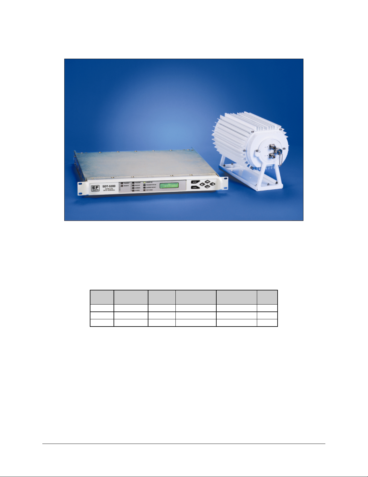
The satellite terminal system is designed for maximum reliability and performance in the
C-Band (Figure 1-1) or Ku-Band (Figure 1-2) applications.
Figure 1-1. The C-Band (C5) System
Rev. 0 1–1
Page 22
Introduction C5/K1/K3 Integrated Satellite Terminal System
Figure 1-2. The Ku-Band (K1 or K3) System
Refer to Table 1-1 for a matrix of customer-selectable configured units.
Table 1-1. Customer-Selectable Configured Units
ODU ODU ODU
System IDU C-Band Ku-Band 1W Ku-Band 3W LNA
C5 SDT-5200 X X
K1 SDT-5200 X
K3 SDT-5200 X
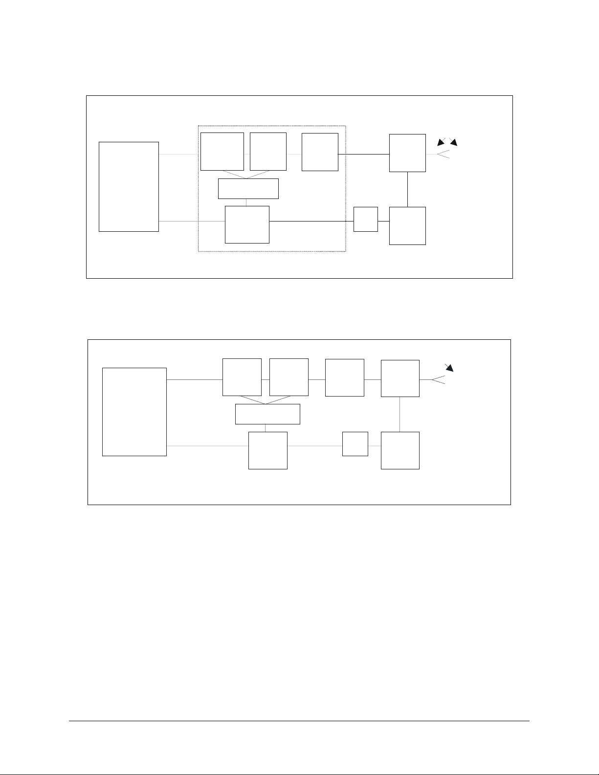
C-Band System - A block diagram (Figure 1-3) illustrates the system as a single thread,
single channel per carrier per carrier (SCPC), very small aperture terminal (VSAT)
consisting of a full featured modem, an up converter/transceiver, and a low-noise
amplifier (LNA) designed to meet the needs of single and/or multiple site installations.
Ku-Band System - A block diagram (Figure 1-4) illustrates the system as a single
thread, single channel per carrier per carrier (SCPC), and very small aperture terminal
(VSAT) consisting of a full featured modem and an up converter/transceiver.
The outdoor unit (ODU) is a weatherproof enclosure housing the up converter, solidstate power amplifier, automatic level control, block down converter, IF interfaces,
monitor and control (M&C), and a DC power converter.
1–2 Rev. 0
Page 23
C5/K1/K3 Integrated Satellite Terminal System Introduction
N
ODU ASSY
(NOT PROVIDED)
RE
REJECT
FILTER
OMT
FEED
HORN
MODEM/
IDU
SDT-5200
IFL
CABLES*
UP
CONVERTER
.
HPA
M & C
*OPTIONAL
MODEM/
IDU
*OPTIONAL
IFL
CABLES*
IFL
CABLES*
C
ABLES*
DOWN
CONVERTER
LNA
Figure 1-3. C-Band System Block Diagram
RX
REJECT
FILTER
LNA
REJECT
IFL
UP
CONV
HPA
M & C
DOWN
CONV
TX
REJECT
FILTER
OMT
TX
FILTER
(NOT PROVIDED)
FEED HOR
Figure 1-4. Ku-Band System Block Diagram
Note: Modulator uplink carries power for the ODU, LNA, 50 MHz REF, and coded M&C.
Rev. 0 1–3
Page 24

Introduction C5/K1/K3 Integrated Satellite Terminal System
1.1.1 Description
The SDT-5200 indoor unit (IDU) is a 1 RU rack-mounted module that includes all the
functionality of a variable data rack modem, along with the high-stability reference and
power supply for the ODU.
Microcontrollers in both the IDU and ODU monitor and control all operational
parameters and status of the system. The system also reports terminal configuration
status, as well as fault status of all system components. A simple command set allows
configuration, control, and retrieval of status information.
The C-Band satellite terminal system is divided into three areas of operation:
1. SDT-5200 Indoor Unit (IDU). A complete, variable data rate modem, high
stability references, and power supply for the ODU in a 1 RU package.
2. Outdoor Unit (ODU). A weatherproof C-Band up converter/power amplifier and
a low noise block (LNA) down converter. The ODU is mounted on the spar of
the antenna and is connected via coaxial cables to the IDU and the LNA.
3. Low Noise Amplifier (LNA) Assembly. Consists of a waveguide Transmit
Reject Filter (TRF) and LNA.
C-Band - The ODU accepts a 790 " 11 MHz TXIF signal and transmits it in the 5.925 to
6.425 GHz frequency band. Output power level is controlled by an ALC loop to provide
extremely stable output power regardless of temperature variations.
C-Band - The low noise assembly (LNA) (60#K standard noise temperature) on the OMT
accepts an RF signal in the 3.7 to 4.2 GHz band and amplifies the desired signal to be
received. The ODU down converters converts the signal to an IF of 950 to 1450 MHz.
1–4 Rev. 0
Page 25

C5/K1/K3 Integrated Satellite Terminal System Introduction
The Ku-Band satellite terminal system is divided into two areas of operation:
1. SDT-5200 Indoor Unit (IDU). A complete, variable data rate modem, high
stability references, and power supply for the ODU in a 1 RU package.
2. Outdoor Unit (ODU). The ODU is mounted on the antenna feed horn and
directly connected to the OMT. In addition, it also directly interfaces via two
coaxial cables to the IDU.
Ku-Band - The ODU accepts a 790 " 11 MHz TXIF signal and transmits it in the 14.0 to
14.5 GHz frequency band. The maximum available transmit power is +29 dBm (P1dB)
or +34 dBm (P1dB) depending on the option selected. Output power level is controlled
by an ALC loop to provide extremely stable output power regardless of temperature
variations.
Ku-Band - The ODU accepts an RF signal in one of several Ku frequency bands. The
ODU amplifies, then down-converts the signal to an IF of 950 to 1450 MHz. An
integrated transmit band reject filter prevents the integrated low noise amplifier (LNA)
from being overloaded.
1.1.2 Additional Features
The system contains the following additional features:
Note: These features are fully described in Appendix A.
!
Fully Accessible System Topology (FAST): EFData’s FAST system allows
immediate implementation of different options through the user’s keypad.
!
Sequential Decoder: The sequential decoder is used in Closed Network
applications, typically in Frequency Division Multiple Access (FDMA).
!
Asymmetrical Loop Timing: Asymmetrical loop timing is the same timing
method that is designed into the SDM-650B TROJAN interfaces.
!
INTELSAT Reed-Solomon Operation: The Reed-Solomon Codec works in
conjunction with the interface card to provide concatenated convolutional
encoding and decoding.
!
Automatic Uplink Power Control (AUPC): The AUPC feature works with the
ASYNC option to allow remote communication between a local modem and a
remote modem.
!
Asynchronous Channel Unit Overhead: The asynchronous (ASYNC) interface
option provides the interface for terrestrial data and single ASYNC overhead
channel.
Rev. 0 1–5
Page 26
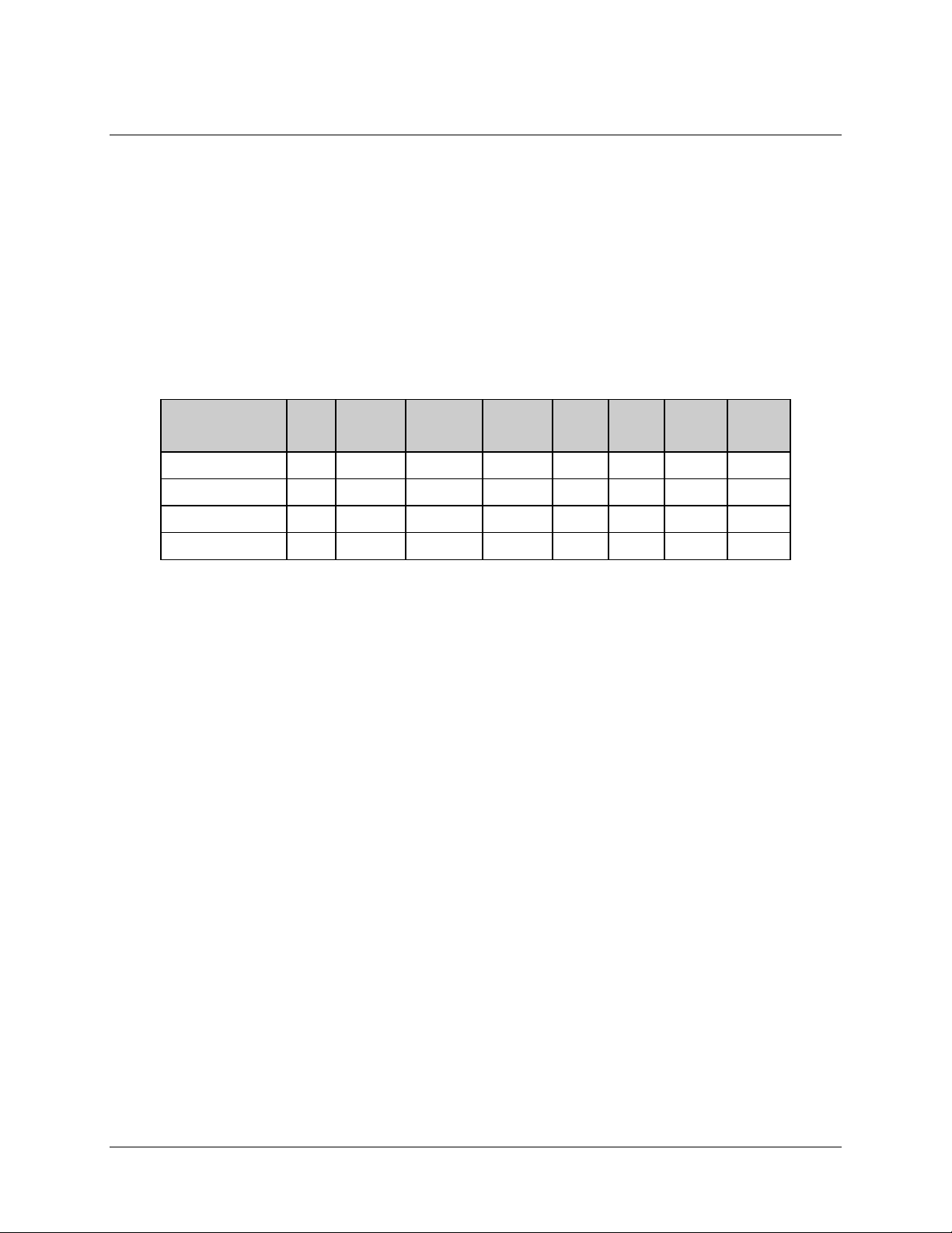
Introduction C5/K1/K3 Integrated Satellite Terminal System
1.2 Modem Feature Upgrade (FAST)
The SDT-5200 indoor unit (IDU) has a variety of options available as shown in Table
1-2. Options are available through conventional means as well as through EFData’s
FAST system. For detailed description of the FAST feature and all options, refer to
Appendix A.
Note: EFData has included a DEMO Mode in the Utility menu. This feature will allow
the operator to experience any of the FAST options. This feature has a 60-minute time
limit, after which, the unit will return to its previous configuration.
Table 1-2. FAST Options
Hardware
Base
SDT-5200
FAST Options to the Base
SDT-5200
FAST Options wi th ReedSolomon Hardware
FAST Options wi th
Overhead Hardware
Single
Data
Rate
X
N/A
N/A
N/A
Variable
Data Rate
(up to
512 kbit/s)
X
N/A
N/A
Variable
Data Rate
(up to 4.375
Mbit/s)
X
N/A
N/A
Sequential
Decoder
X
N/A
N/A
Viterbi
Decoder
X
N/A
N/A
Async
Loop
Timing
X
N/A
N/A
Reed-
Solomon
Codec
N/A
X
N/A
ASYNC/
AUPC
Overhead
N/A
N/A
X
Note: The basic SDT-5200 is shipped with either Sequential or Viterbi decoder.
1–6 Rev. 0
Page 27

C5/K1/K3 Integrated Satellite Terminal System Introduction
1.3 Modes of Operation
The ASYNC/AUPC option allows an additional overhead channel to be multiplexed and
demultiplexed from the data carrier. Two mechanisms are provided for automatic uplink
power control (AUPC) within a closed network.
!
One method, which requires the optional ASYNC/AUPC interface card, is used
for control between two links to sustain sufficient transmit power to maintain a
programmed E
!
The second method is used for self-monitoring the carrier from the same uplink
with the local demodulator, requires no additional hardware, and is softwareselectable. This method is appropriate for applications such as paging networks,
where the uplink is transmit-to receive only devices. The self-monitoring AUPC
function is not available when the ASYNC/AUPC interface option is installed.
The IDU interfaces between Single-Channel per Carrier (SCPC) fixed-rate terminal
equipment operating within the following specifications:
at both ends.
b/N0
!
The IDU is capable of data rates from 2.4 kbit/s to 4.375 Mbit/s and includes a
-9
1 x 10
/day standard internal frequency reference.
Note: The IDU can be configured to add overhead/framing to the data.
Available modulation types include:
!
Bi-Phase Shift Keying (BPSK).
!
Quadrature Phase Shift Keying (QPSK).
An internal channel unit, conforming to IESS-308 and -309 emulation specifications,
provides overhead designated for an Engineering Service Channel (ESC).
Rev. 0 1–7
Page 28
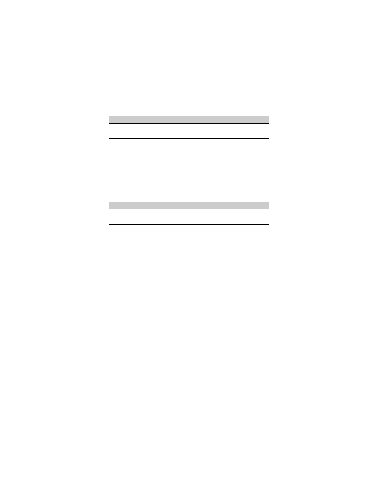
Introduction C5/K1/K3 Integrated Satellite Terminal System
1.4 Component Description
The C-Band (Figure 1-3) is divided into three distinct areas of operations:
Table 1-3. C-Band Three Areas of Operation
Model/Part No. Component
SDT-5200 Satellite Data Terminal
Type 30-0120-172 Outdoor Unit
Model No. 6307 Low Noise Amplifier
The Ku-Band (Table 1-4) is divided into two distinct areas of operations:
Table 1-4. Ku-Band Two Areas of Operation
Model/Part No. Component
SDT-5200 Satellite Data Terminal
1W or 3W Ku-Band Outdoor Unit
1–8 Rev. 0
Page 29
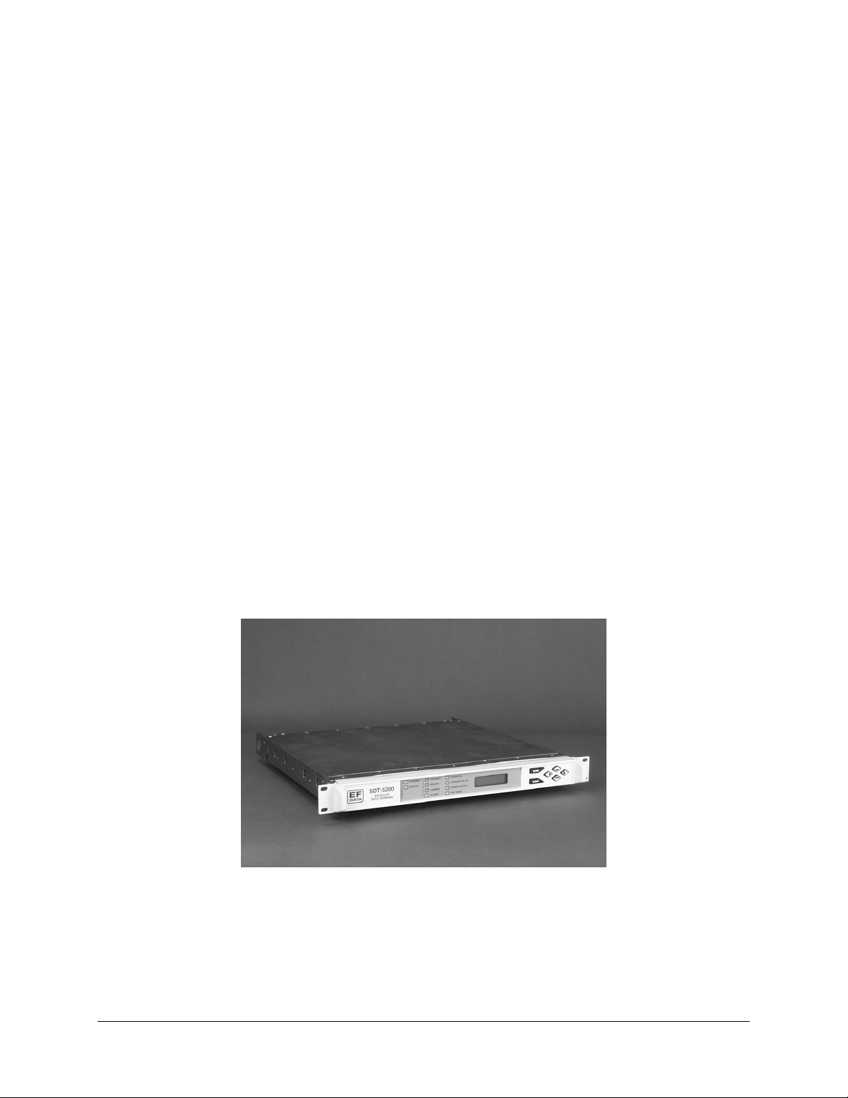
C5/K1/K3 Integrated Satellite Terminal System Introduction
1.4.1 SDT-5200 Indoor Unit
The SDT-5200 Indoor unit (Figure 1-5), here after referred to as the IDU, is divided into
four sections:
!
Modulator
!
Demodulator
!
Interface
!
Monitor and Control (M&C)
Modulator - The modulator converts the baseband data to a shaped, modulated IF from
779 to 801 MHz. The modulator output also provides the M&C control link, DC power,
and reference for the terminal outdoor unit.
Demodulator – The demodulator converts an IF of 950 to 1450 MHz down to baseband.
Interface – The interface provides a link between the Digital Test Equipment (DTE) and
the modem. Several industry-standard interfaces are available, as well as EFData
proprietary.
Monitor & Control – The M&C uses a microcontroller to control all operational
parameters and monitor system status. The system also reports modem configuration
status, as well as fault status of the modem. A simple command set allows configuration,
control, and retrieval of status information.
Figure 1-5. SDT-5200 Indoor Unit
Rev. 0 1–9
Page 30
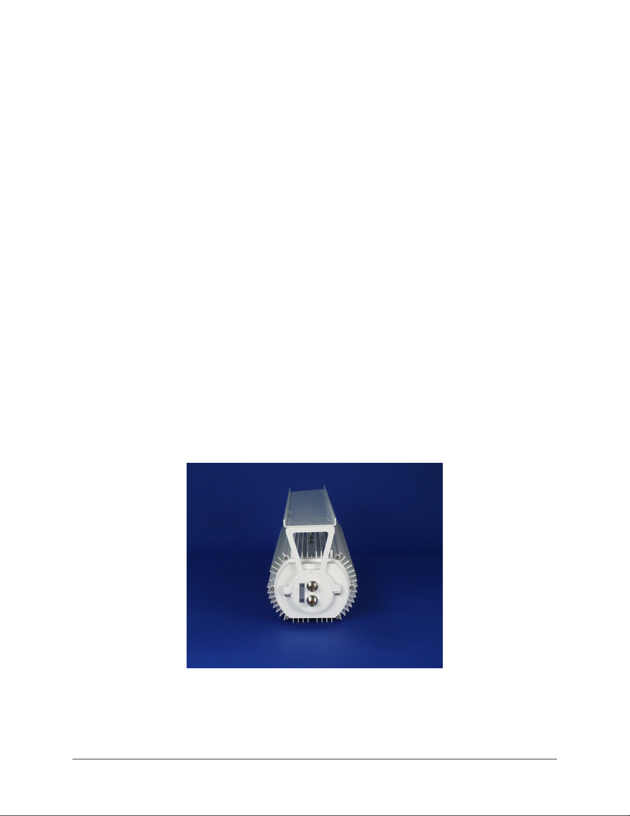
Introduction C5/K1/K3 Integrated Satellite Terminal System
1.4.2 C-Band Outdoor Unit (ODU)
The ODU (Figure 1-6) consists of the following assemblies:
!
Power Amplifier
!
Up Converter/Block Down Converter
!
Automatic Level Control
!
Data Link for Fault Sensing and Control
!
Switching Power Converter
!
Radio Frequency Terminal
The ODU is a weatherproof C-Band up converter/transmitter that automatically adjusts
for cable losses and changes between the IDU and the ODU. The transmit (TX) power
level can be adjusted between +27 to +34 dBm. The ODU interfaces to the IDU using a
two coaxial cables. The cables consist of the following signals:
!
Cable No.1
TX signal
$
M&C link
$
Reference OSC
$
DC power
$
!
Cable No. 2
RX signal
$
Figure 1-6. C-Band ODU
1–10 Rev. 0
Page 31

C5/K1/K3 Integrated Satellite Terminal System Introduction
1.4.3 Ku-Band Outdoor Unit (ODU)
The Ku-Band ODU (K1 or K3) is a weatherproof, enclosed unit, housing the up
converter, solid-state power amplifier, automatic level control, integrated low-noise
amplifier (LNA), block down converter, IF interface, monitor and control (M&C), and
DC power converter.
The ODU connects directly to the OMT and is cabled to the transmit and receive
connectors of the IDU.
The ODU consists of the following assemblies:
!
Power Amplifier
!
Up Converter
!
Automatic Level Control
!
Data Link for Fault Sensing and Control
!
Switching Power Converter
!
LNA converter (Internal)
The ODU is a weatherproof Ku-Band up converter/transmitter that automatically adjusts
for cable losses and changes between the IDU and the ODU. The transmit (TX) power
level can be adjusted between +29 to +34 dBm. The ODU interfaces to the IDU using a
pair of coaxial cables, consisting of the following signals:
!
One Cable
TX signal
$
M&C link
$
Reference OSC
$
DC power
$
!
Second Cable
$
RX signal
Figure 1-7. Ku-Band ODU
Rev. 0 1–11
Page 32

Introduction C5/K1/K3 Integrated Satellite Terminal System
1.4.4 Low-Noise Phase-Locked Amplifier (LNA)
Note: This component is used in the C5 system only.
LNA (Figure 1-8) consists of a waveguide Transmit Reject Filter (TRF). The LNA
standard noise temperature is 60#K. The LNA’s DC power is supplied from the ODU.
The LNA is mounted to the OMT and is cabled to the ODU.
Figure 1-8. LNA
1–12 Rev. 0
Page 33

C5/K1/K3 Integrated Satellite Terminal System Introduction
1.5 Options
The following options (Table 1-5 )are applicable to the Ku-Band configuration only.
Refer to for Ku-Band options.
Table 1-5. Ku-Band Options
Description Options
Transmit Power 0.8W
2.5 W
Receive Frequency Band 10.95 to 11.45 GHz
11.2 to 11.7 GHz
11.7 to 12.2 GHz
12.25 to 12.75 GHz
Rev. 0 1–13
Page 34

Introduction C5/K1/K3 Integrated Satellite Terminal System
This page is intentionally left blank.
1–14 Rev. 0
Page 35

SPECIFICATIONS
2
The chapter provides the necessary specif ica ti ons for the Sat el lite Terminal System.
2.1 C-Band System Specifications
Refer to Table 2-1 for the C-Band system specifications.
Table 2-1. C-Band System Specifications
Parameter Specifications
TX Band 5.925 to 6.425 GHz
RX Band 3.7 to 4.2 G H z
RF Output Connector Type N, female (on ODU)
RF Input Connector CPR229G Wave Guide (on LNA assembly)
LNA/ODU Interconnect
ODU/OMT Interconnect
IDU/ODU Interconnect:
50!, N male connectors – both sides
50!, N male connectors – both sides
0.5 dB maximum attenuation at 3.7 to 4.2 GHz
Two coaxial cables
Chapter 2
TX Cable
RX Cable
Rev. 0 2–1
50!, N male connectors – both sides
20 dB maximum attenuation at 790 MHz, 2! maximum
50!, N male connectors – both sides
25 dB maximum attenuation at 950 to 1450 MHz, 2
maximum
!
Page 36

Specifications C5/K1/K3 Integrated Satellite Terminal System
Table 2-1. C-Band System Specifications (Continued)
Parameter Specifications
Data I/O Connector EIA-530-A, 25-pin D-sub, female (EIA-422, EIA-232, V.35)
EIA-449, 37-pin D-sub, female (EIA-422) – optional
EFD Standard, 50-pin D-sub, female – (ASYNC) – optional
V.35, 34-pin Winchester - optional
Alarm Connector Form-C Contact, 9-pin D-sub, female
Fault Connector Form-C Contact, 9-pin D-sub, female
Auxiliary Connector Open Collector, 9-pin D-sub, female
Remote Connector EIA-232 or EIA-485, 9-pin D-sub, female
Prime Power – IDU 85 to 264 VAC, 47 to 63 Hz, using a 6-foot (2-meter) cable with a
3-prong plug.
Meets EFData QUA_014 Operating Procedure.
Power Consumption:
Total System 150W maximum
Agency Compliance:
Safety
Emissions
Susceptibility
CE MARK – EN60950
CE MARK – EN55022-1
CE MARK – EN50082-1
2–2 Rev. 0
Page 37

C5/K1/K3 Integrated Satellite Terminal System Specifications
2.1.1 C-Band Receive Specifications
Refer to Table 2-2 for receive specifica tion s.
Table 2-2. C-Band Receive Specifications
Parameter Specifications
Frequency Rang e 3.7 to 4.2 GHz
Frequency Resolution 100 Hz
Noise Figure
RX Image Rejection 45 dBm minimum
Aggregate Signal Level ,
Maximum
Symbol Rate Range (variable) 4.8 to 2500 ks/s
Data Rate Range (variable):
QPSK
BPSK
Forward Error Correction Viterbi K = 7 decoder, 1/2, 3/4, and 7/8 rate
Modulator Output IF Shape EFD Closed
Demodulation Coherent QPSK or BPSK
Acquisition Range 0 to 70 kHz in 1 Hz steps
Bit Error Rate (BER):
Viterbi 1/2 rate
Viterbi 1/2 rate with Reed-
Solomon
Ambiguity Resolution Method Differential decoder
Descrambling CCITT V.35 IESS modified, CCITT V.35 (EFD/CSC), FDC, 215-1
Clock Jitter 2.0 dB maximum jitter gain, 4% RMS of 1/data rate absolute.
20 dB
"
-27 dBm at ODU down converter input
4.8 to 4375 kbit/s, in 1 bit/s steps
2.4 to 1250 kbit/s, in 1 bit/s steps
Optional: Sequential k = 36 1/2, 3/4 and 7/8 rate
Optional: Reed-Solomon IESS 308/309
Concatenated 225, 205, T = 10.
CSC Closed
FDC Closed
-8
for Eb/N0 7.2 dB
1 x 10
-10
1 x 10
SYNC
for Eb/N0 5.0 dB
Rev. 0 2–3
Page 38

Specifications C5/K1/K3 Integrated Satellite Terminal System
2.1.2 C-Band Transmit Specifications
Refer to Table 2-3 for transmit specif ica tio ns.
Table 2-3. C-Band Transmit Specification
Parameter Specifications
Frequency Range 5.925 to 6.425 GHz, in 100 H z s te ps
Frequency Resolution 100 Hz
Maximum Power (P1db)
Power Range +25 to +38 dBm, measur e d w ith a CW sig na l at ODU output c onne c t or
Power Resolution 0.1 dB steps
Output S/N Ratio
Power Accur acy
Power Flatness
Power Temperature Stability
Group Delay Var iation
3rd IMD Intercept Point +44 dBm minimum measur e d with tw o c a rr iers 17 dB below inte rce pt
TX Frequency Drift/Temperature (IDU)
Daily Frequency Stability
Annual Reference Freque ncy Aging
TX Phase Noise
Undesired Sideband Suppre s s ion
Carrier Suppress ion
Spurious
Harmonics
RF OFF Level
C-Band Output VSWR
Symbol Rate Range (variable ) 4.8 to 2500 ks/s
Data Rate Range (variable):
QPSK
BPSK
Modulator Output IF Shape EFD Closed
Modulation Coherent QPSK or BPSK
Forward Error Correction Viterbi K = 7 decoder, 1/2 3/4, and 7/8 rate
Scrambling CCITT V.35 IESS modified, CCITT V.35 (EFD/CSC), FDC, 215-1
+37 dBm, measured with a CW sig na l at O DU output c onne c tor
#
50 dB
$
1.5 dB at +37 dBm
%
2.0 dB at +27 dBm
%
0.2 dB over any 1 MHz se gm e nt
"
0.75 dB maximum -40& to +55&C (-40& to +131&F)
%
25 ns, over any 2.5 MHz s egm e nt
"
point at TX output with ALC ON m eas ure d with CW s ignal .
1 x 10⁻⁸ from 0& to +50&C (32& to 122&F)
%
1 x 10⁻⁹ (at constant tempera ture )
%
5 x 10⁻⁸ (front panel adjustment for lifetime aging)
'
-65 dBc/Hz at 100 Hz
'
-70 dBc/Hz at 1 kHz
'
-70 dBc/Hz at 10 kHz
'
-75 dBc/Hz at 100 kH z
'
or < 2.8& RMS SSB integrated 100 Hz to 1 MHz a t # +27 dBm output
-30 dBc
'
-35 dBc
'
-15 dBm
'
-20 dBc
'
-30 dBm
'
1.5:1, 50!, 5.925 to 6.425 GHz
"
4.8 to 4375 kbit/s, in 1 bit/s steps
2.4 to 1250 kbit/s, in 1 bit/s steps
CSC Closed
FDC Closed
Optional: Sequential k = 36, 1/2, 3/4, and 7/8 rate
Optional: Reed-Solomon IESS 308/309
Concatenated 225, 205, T = 10.
SYNC
2–4 Rev. 0
Page 39
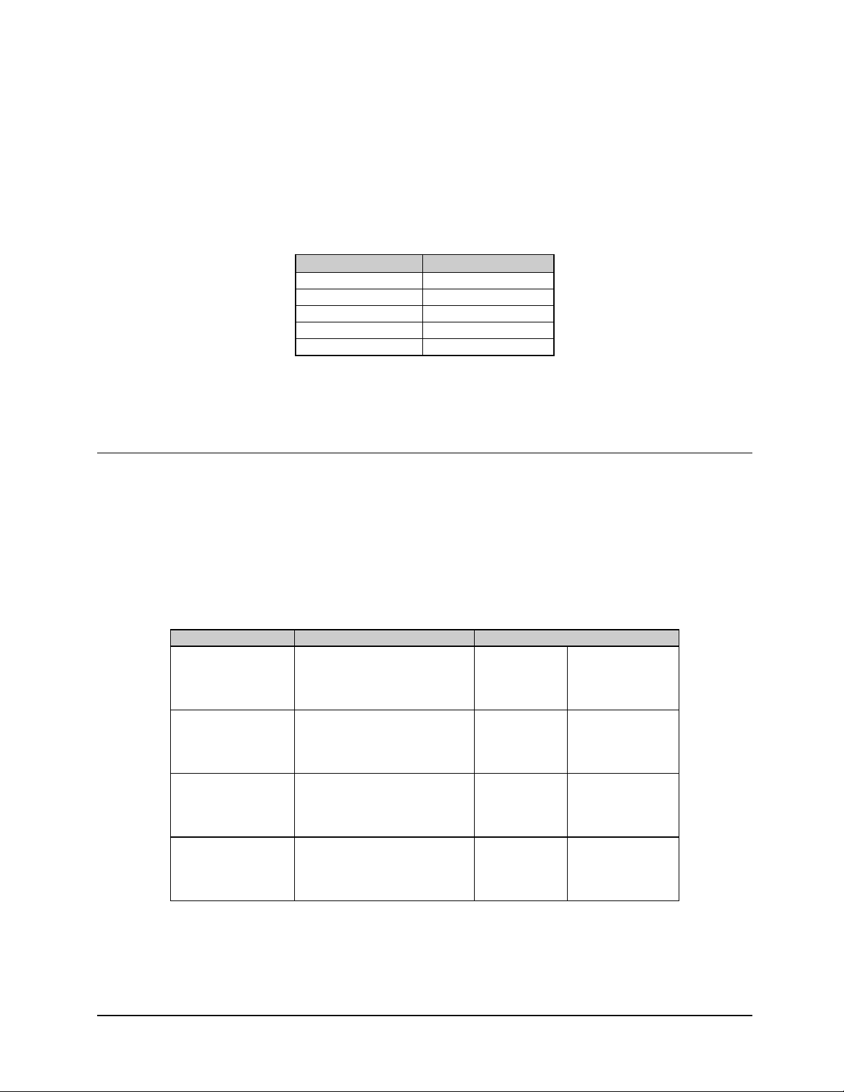
C5/K1/K3 Integrated Satellite Terminal System Specifications
2.1.3 C-Band Transmit Reject Filter Specifications
Refer to Table 2-4 for transmit reject fi lter spec if ic at ions.
Table 2-4. C-Band TX Reject Filter Specifications
Parameter Specifications
Passband 3.7 to 4.2 GHz
Insertion Loss 0.035 dB maximum
Stop Band 5.85 to 6.425 GHz
Rejection 55 dB minimum
Flange Connection CPR-229 G
2.1.4 C-Band Modulator-Related Specifications
2.1.4.1 Digital Data Rate
The digital data rate (Table 2-5) selectable in 1 Hz steps. The symbol rate is automatically
calculated based on the programmed data rate. Data rates entered that exceed the data rate
or symbol rate specification are rejected at entry.
The symbol rate range is 4.8 to 2500 ks/s.
Table 2-5. C-Band Digital Data Rate
Modulation Type Encoding Type Data Rate Range
BPSK 1/2
QPSK 1/2
QPSK 3/4
QPSK 7/8
BPSK 1/2
QPSK 1/2
QPSK 3/4
QPSK 7/8
BPSK 1/2
QPSK 1/2
QPSK 3/4
QPSK 7/8
BPSK 1/2
QPSK 1/2
QPSK 3/4
QPSK 7/8
Viterbi
Viterbi
Viterbi
Viterbi
Sequential
Sequential
Sequential
Sequential
Viterbi and Reed-Solomon
Viterbi and Reed-Solomon
Viterbi and Reed-Solomon
Viterbi and Reed-Solomon
Sequential and Reed-Solomon
Sequential and Reed-Solomon
Sequential and Reed-Solomon
Sequential and Reed-Solomon
2.4 kbit/s
4.8 kbit/s
7.2 kbit/s
8.4 kbit/s
2.4 kbit/s
4.8 kbit/s
7.2 kbit/s
8.4 kbit/s
2.4 kbit/s
4.8 kbit/s
7.2 kbit/s
8.4 kbit/s
2.4 kbit/s
4.8 kbit/s
7.2 kbit/s
8.4 kbit/s
1.25 Mbit/s
2.5 Mbit/s
3.75 Mbit/s
4.375 Mbit/s
1.25 Mbit/s
2.5 Mbit/s
3.75 Mbit/s
4.375 Mbit/s
1.138 Mbit/s
2.277 Mbit/s
3.416 Mbit/s
3.986 Mbit/s
1.138 Mbit/s
2.277 Mbit/s
3.416 Mbit/s
3.986 Mbit/
Note: In ASYNC overhead operation, the maximum data rate is limited to 2048 kbit/s for QPSK
modulation, and 1024 kbit/s for BPSK modulation.
Rev. 0 2–5
Page 40

Specifications C5/K1/K3 Integrated Satellite Terminal System
2.1.4.2 Modulation and Encoding Types
Refer to Table 2-6 for combinations of modulatio n and forward er ror cor rec tio n encodi ng .
Table 2-6. C-Band Modulation Encoding Types
Encoder Code Rate Modulation
Viterbi, K7 1/2 BPSK
Viterbi, K7
Reed-Solomon
Viterbi, K7 1/2, 3/4, 7/8 QPSK
Viterbi, K7
Reed-Solomon
Sequential 1/2 BPSK
Sequential
Reed Solomon
Sequential (EFD, CSD, FDC) 1/2, 3/4, 7/8 QPSK
Sequential
Reed-Solomon
1/2
225/205 Closed
1/2, 3/4, 7/8
225/205 Closed
1/2
225/205 Closed
1/2, 3/4, 7/8
225/205 Closed
BPSK
BPSK
QPSK
QPSK
BPSK
BSPK
QPSK
QPSK
Note: Reed-Solomon concatenated coding uses INTELSAT IESS 308/309 polynomial and
is fully capable with SDM-300/SDM-300A closed network operation.
2.1.4.3 Scrambling Types
The customer may select one of the following:
(
CCITT V.35 (EFData/Comstream compatible). Sequential only.
(
CCITT V.35 INTELSAT modified. Viterbi only.
(
Fairchild compatible. Sequential only.
15
(
(
(
–1 Synchronous for use in ASYNC overhead mode.
2
Modified V.35 (Closed Network Reed-Solomon).
None.
2.1.4.4 Interleaver (Reed-Solomon Codec)
Depth 8 (Closed Network, ASYNC).
Note: The Reed-Solomon depth 8 interleaver is based on the IESS-310 specification for
8PSK and is adapted for QPSK/PRSK operation.
2–6 Rev. 0
Page 41

C5/K1/K3 Integrated Satellite Terminal System Specifications
2.1.5 C-Band Transmit (TX)
2.1.5.1 Transmit Frequency
The operator can select the center frequency of the output spectrum from 5.925 to
6.425 GHz, in 100 Hz steps.
2.1.5.2 Transmit Frequency Reference
The standard internal reference fr equen cy has a stability-over-temperature of
% 0.001 PPM.
The internal high stability oxcillator can be adjusted from the front panel to calibrated and
counteract aging of the crystals.
2.1.5.3 Phase Noise
Note: Phase noise and RMS phase deviation ( Table 2-7)shall be met at all times, at all
frequencies, at all temperatures, and at all power levels.
Table 2-7. C-Band Phase Noise
Condition Specification
Phase noise of the transmit output
carrier
RMS Phase Deviation
Output Signal to Noise Ratio
2.1.5.4 Transmit Output Switch
When set to OFF, no signal present at the wave-guide flange is greater than -60 dBm,
measured in a 3 kHz
bandwidth.
dBc/Hz
-65.0
-70.0
-70.0
-75.0
10 Hz to 1 MHz, " 2.8&
# 50 dB
Offset from Carrier
100 Hz
1 kHz
10 kHz
100 kHz
Rev. 0 2–7
Page 42

Specifications C5/K1/K3 Integrated Satellite Terminal System
2.1.5.5 Transmit Power
(
The transmit power is operator-selectable from +25 to +38 dBm, in 0.1 dB steps.
(
The maximum drift due to temperature change is %
the ODU is used.)
0.75 dB. (The ALC feature of
(
The transmit power accuracy is %
(
The transmit output is flat within 0.2 dB over any 1 MHz segment.
2.1.5.6 Modulated Output Shape
The terminal meets the following transmit output spectral mask specifications, subject to
the limitations of a 50 dB S/N ratio. The desired mask is selectable from the front panel or
remotely.
(
Closed Network (EFData/Comstream)
(
Closed Network (Fairchild compatible)
2.1.5.7 Spurious Emissions
Spurious emissions are measured at the C-Band ODU output Type N female connector.
The measurement is done with the carrier ON, in continuous mode, and modulated by the
correct data/clock signal.
(
Spurious emissions measured in a 3 kHz bandwidth at the transmit output are
" -15 dBm from 3.7 to 8 GHz, excluding a band % 1 MHz from the carrier.
2.0 dB at +25 dBm and % 1.5 dB at +38 dBm.
(
Spurious emissions measured in a 3 kHz bandwidth from 3.7 to 4.2 GHz are
" -100 dBm.
(
The carrier is suppressed to " -35 dBc in normal operating mode.
(
The undesired sidebands of the modulated signal is suppressed to " -35 dBc.
(
The harmonics of the modulated signal is ' -20 dBc.
2–8 Rev. 0
Page 43

C5/K1/K3 Integrated Satellite Terminal System Specifications
2.1.6 C-Band Transmit Test Modes
The following transmit test modes are available to the customer. Spurious emissions in the
following test modes will be " -30 dBc.
(
CW – Outputs a single carrier at the defined frequency.
(
Offset – Dual sideband signal with lower sideband and carrier
suppressed " 30 dBc.
(
Dual sideband – Suppressed carrier
" 30 dBc.
2.1.7 C-Band Modulator Spectrum Rotation
The customer can select normal or inverted spectrum of the Modulator Output.
2.1.8 C-Band Output VSWR
The VSWR into a 50! load is " 1.5:1 for the frequency range of 5.925 to 6.425 GHz.
2.1.9 C-Band Transmit Frequency Change Time
Upon receiving a command to change the TX RF frequency, the terminal reprograms the
IDU and ODU accordingly. The transmit frequency is stable in ' 500 ms.
Rev. 0 2–9
Page 44

Specifications C5/K1/K3 Integrated Satellite Terminal System
2.1.10 C-Band Demodulator-Related Specifications
2.1.10.1 Digital Data Rate
The digital data rate (Table 2-8) is selectable in 1 bit/s steps. The symbol rate is
automatically calculated on the programmed data rate. Data rates entered that exceed the
data rate or symbol rate specification are rejected at entry.
The symbol rate range is 4.8 to 2500 ks/s.
Table 2-8. C-Band Digital Data Rate
Modulation Type Decoding Type Data Rate Range
BPSK 1/2
QPSK 1/2
QPSK 3/4
QPSK 7/8
BPSK 1/2
QPSK 1/2
QPSK 3/4
QPSK 7/8
BPSK 1/2
QPSK 1/2
QPSK 3/4
QPSK 7/8
BPSK 1/2
QPSK 1/2
QPSK 3/4
QPSK 7/8
Viterbi
Viterbi
Viterbi
Viterbi
Sequential
Sequential
Sequential
Sequential
Viterbi and Reed-Solomon
Viterbi and Reed-Solomon
Viterbi and Reed-Solomon
Viterbi and Reed-Solomon
Sequential and Reed-Solomon
Sequential and Reed-Solomon
Sequential and Reed-Solomon
Sequential and Reed-Solomon
2.4 kbit/s
4.8 kbit/s
7.2 kbit/s
8.4 kbit/s
2.4 kbit/s
4.8 kbit/s
7.2 kbit/s
8.4 kbit/s
2.4 kbit/s
4.8 kbit/s
7.2 kbit/s
8.4 kbit/s
2.4 kbit/s
4.8 kbit/s
7.2 kbit/s
8.4 kbit/s
1.25 Mbit/s
2.5 Mbit/s
3.75 Mbit/s
4.375 Mbit/s
1.25 Mbit/s
2.5 Mbit/s
3.75 Mbit/s
4.375 Mbit/s
1.138 Mbit/s
2.277 Mbit/s
3.416 Mbit/s
3.986 Mbit/s
1.138 Mbit/s
2.277 Mbit/s
3.416 Mbit/s
3.986 Mbit/s
Note: In ASYNC overhead operation, the maximum data rate is limited to 2048 kbit/s for
QPSK modulation, and 1024 kbit/s for BPSK modulation.
2–10 Rev. 0
Page 45
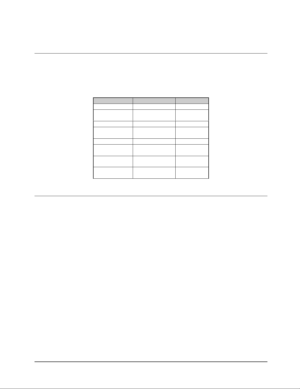
C5/K1/K3 Integrated Satellite Terminal System Specifications
2.1.10.2 Demodulation and FEC Decoding Types
Refer to Table 2-9 for combinations of modulatio n and forward er ror cor rec tio n (FEC)
encoding.
Table 2-9. C-Band Modulation and Encoding Types
Encoder Code Rate Modulation
Viterbi, K7 1/2 BPSK
Viterbi, K7
Reed-Solomon
Viterbi, K7 1/2, 3/4, 7/8 QPSK
Viterbi, K7
Reed-Solomon
Sequential 1/2 BPSK
Sequential
Reed-Solomon
Sequential (EFD,
CSD, FDC)
Sequential
Reed-Solomon
1/2
225/205 Closed
1/2, 3/4, 7/8
225/205 Closed
1/2
225/205 Closed
1/2, 3/4, 7/8 QPSK
1/2, 3/4, 7/8
225/205 Closed
BPSK
BPSK
QPSK
QPSK
BPSK
BSPK
QPSK
QPSK
2.1.10.3 Descrambling Types
The customer may select one of the following:
(
CCITT V.35 (EFData/Comstream compatible). Sequential only.
(
CCITT V.35 INTELSAT modified. Viterbi only.
(
Fairchild compatible. Sequential only.
(
215-1 Synchronous for use in ASYNC overhead mode.
(
Modified V.35 (Closed Network Reed-Solomon).
(
None.
Rev. 0 2–11
Page 46

Specifications C5/K1/K3 Integrated Satellite Terminal System
2.1.10.4 Deinterleaver (Reed-Solomon Codec)
Depth 8 (Closed Network).
Note: The Reed-Solomon depth 8 deinterleaver is based on the IESS-310 specification for
8PSK and is adapted for QPSK/BPSK operation.
2.1.10.5 Receive Frequency
The receive frequency can be selected by the user from 3.7 to 4.2 GHz, in 100 Hz steps.
The actual value of offset from the programmed frequency is available to the user on the
;
front panel as well as the remote port. The resolution of this value is 1 Hz
the accuracy is
% 25 kHz.
2.1.10.6 Receive Input Power (Composite)
The terminal can operate to its specified performance under all of the following
conditions:
(
The sum of all carriers and noise in receive band is " -27 dBm at the ODU down
converter input.
(
The sum of all carriers within 10 MHz from the desired is
the desired carrier.
(
The sum of all carriers is " +50 dBc relative to the desired carrier for operation at
64 ks/s and below, or
" +40 dBc at $ 64 ks/s operation.
2.1.10.7 Demodulator IF Input Shape
The terminal can be set to match any of the following spectral mask specifications:
(
Closed Network (EFData/Comstream).
(
Closed Network (Fairchild compatible).
" +30 dBc relative to
2–12 Rev. 0
Page 47

C5/K1/K3 Integrated Satellite Terminal System Specifications
2.1.10.8 Channel Spacing/Adjacent Carrier Performance
The terminal bit error performance will be degraded < 0.5 dB with the following receive
signal:
(
Two like-modulated carriers spaced 1.3 times the symbol rate from the receive
frequency, and/or 1.2 times the acquisition range, whichever is larger.
(
Each adjacent carrier up to 10 dBc higher in power than the desired carrier.
(
Single adjacent carrier spaced 1.4 times symbol rate up to +20 dBc higher in
power than the desired carrier.
Rev. 0 2–13
Page 48

Specifications C5/K1/K3 Integrated Satellite Terminal System
This page is intentionally left blank.
2–14 Rev. 0
Page 49

C5/K1/K3 Integrated Satellite Terminal System Specifications
2.2 Ku-Band System Specifications
Refer to Table 2-10 for system specificatio ns.
Table 2-10. Ku-Band System Specifications
Parameter Specification
Transmit Band 14.0 to 14.5 GHz
Receive Band 10.95 to 11.45 GHz
11.20 to 11.7 GHz
11.70 to 12.2 GHz
12.25 to 12.75 GHz
OMT/FEED Interface Circular Waveguide Flange (WC-75)
IDU/ODU interconnect:
TX Cable
50!, N male connector (both ends)
20 dB maximum atten at 790 MHz, 2! maximum
RX Cable
APS Connector Type N female with waterproof cap
Data I/O Connector EIA-530. 25-pin D sub, female (EIA-422, EIA-232, V.35)
Alarm Connector Form C Contact, 9-pin D sub, female
Fault Connector Form C Contact, 9-pin D sub, female
Auxiliary Connector Open Collector, 9-pin D sub, female
Prime Power – IDU 8.5 to 264 VAC, 47 to 63 Hz, using a 6 foot (2 meter) cable 3-prong plug:
Power Consumption Total System –AC 225W maximum
Agency Compliance:
Safety
Emission
Susceptibility
50!, N male connector (both ends)
25 dB maximum atten at 950 to 1450 MHz, 2! maximum
DC voltage corresponding to IDU RX signal level
EIA-449, 37-pin D sub, female (EIA-422) Optional
EFD Standard, 50-pin D sub, female (ASYNC) Optional
V.35, 34-pin Winchester Optional
Meets EFData QUA_014 Operating Procedures
K1 – 0.8W
K3 – 2.5W
CE MARK – EN60950
CE MARK – EN60950
CE MARK – EN50082-1
Rev. 0 2–15
Page 50

Specifications C5/K1/K3 Integrated Satellite Terminal System
2.2.1 Ku-Band Transmit Specifications
Refer to Table 2-11 for Ku-Band transmit specifications.
Table 2-11. Ku-Band Transmit Specifications
Parameter Specification
Frequency Range 14.0 to 14.5 GHz
Frequency Resolution 100 Hz
Maxi mum Po wer (P1dB)
Power Range +17 to +30 dBm or +22 to +35 dBm, measured with a CW signal
Power Resolution 0.1 dB steps
Output S/N Ratio > 50 dB
Power Accuracy
Power Flatness
Power Temperature Stability
Group Delay Variation
3rd IMD Intercept Point +44 dBm minimum, measured with two carriers 17 dB below intercept point
Transmit Frequency Drift/Temperature
Daily Frequency Stability
Annual Reference Frequency Aging < 5 x 10⁻⁸ (front panel adjustment for lifetime aging)
Transmit Phase Noise
Undesired Sideband Suppression < -30 dBc
Carrier Suppression < -35 dBc
Spurious < -13 dBm
Harmonics < -20 dBc
RF Off Level < - 30 dBm
Ku-Band Output VSWR
Symbol Rate Range (Variable) 4.8 to 2500 ks/s
Data Rate Range (Variable):
QPSK
BPSK
Modulator Output IF Shape EFD Closed, CSC Closed, FDC Closed
Modulation Coherent QPSK or BPSK
Forward Error Correction Viterbi K = 7, 1/2, 3/4, 7/8 rate
Scrambling CCITT V.35 IESS modified, CCITT V.35 (EFD/CSC). FDC, 215-1 SYNC
+30 dBm or # +35 dBm, measured with a CW signal
#
1.5 dB at maximum power
%
2.0 dB at maximum power
%
0.2 dB over any 1 MHz segment
"
0.75 dB, maximum –40& to +55&C (–40& to +127&F)
%
25 ns p-p, over any 2.5 MHz segment
"
at transmit output with ALC ON measured with CW signal
1 x 10⁻⁸ from 0& to +50&C (32& to 122&F) (IDU)
%
1 x 10⁻⁹ (at constant temperature)
%
< 3.0& RMS SSB integrated 100 Hz to 1 MHz
1.5:1, 50!, 14.0 to 14.5 GHz
"
4.8 to 4375 kbit/s, in 1.0 bit/s steps
2.4 to 1250 kbit/s, in 1.0 bit/s steps
Optional: Sequential K = 36, 1/2, 3/4, 7/8 rate
Optional: Reed-Solomon IESS 308/309 Concatenated 225.205 T = 10
2–16 Rev. 0
Page 51

C5/K1/K3 Integrated Satellite Terminal System Specifications
2.2.2 Ku-Band Receiver Specifications
Refer to Table 2-12 for Ku-Band receiver speci fic at ions.
Table 2-12. Ku-Band Receiver Specifications
Parameter Specifications
Frequency Rang e 10.95 to 11.45 GHz
11.2 to 11.7 GHz
11.7 to 12.2 GHz
12.25 to 12.75 GHz
Frequency Resolution 100 Hz
System Noise Figure < 160 K
Receive Image Rejection 30 dB, minimum
Maximum Aggregate Signal Level -75 dBm at ODU OMT input
Symbol Rate Range (Variable) 4.8 to 2500 ks/s
Data Rate Range (Variable):
QPSK
BPSK
Forward Correction Viterbi K = 7 Decoder, 1/2, 3/4, 7/8 rate
Demodulator IF Shape EFD Closed, CSC Closed, FDC Closed
Demodulation Coherent QPSK or BPSK
Acquisition Range 0 to 70 kHz, in 1 Hz steps
Bit Error Rate:
Viterbi 1/2 Rate
Viterbi 1/2 Rate with Reed-Solomon
Ambiguity Resolution Method Differential Decoder
Data Buffer 0 to 50 ms in 1ms steps
Descrambling CCITT V.35 IESS modified, CCITT V.35 (EFD/CSC), FDC, 215-1
Clock Jitter 2.0 dB maximum jitter gain, 4% RMS of 1/data rate absolute
4.8 to 4375 kbit/s, in 1.0 bit/s steps
2.4 to 1250 kbit/s, in 1.0 bit/s steps
Optional: Sequential K = 36, 1/2, 3/4, 7/8 rate
Optional: Reed-Solomon IESS 308/309 Concatenated 225.205 T = 10
-8
for Eb/N0 7.2 dB
1 x 10
-10
1 x 10
SYNC
for Eb/N0 5.0 dB
Rev. 0 2–17
Page 52

Specifications C5/K1/K3 Integrated Satellite Terminal System
2.2.3 Ku-Band Modulator-Related Specifications
2.2.3.1 Digital Data Rate
The digital data rate (Table 2-13) is selectable in 1 Hz steps. The symbol rate is
automatically calculated based on the programmed data rate. Data rates that exceed the
data rate or symbol rate specification are rejected at entry.
The symbol rate range is 4.8 kHz to 2.5 MHz.
Table 2-13. Ku-Band Digital Data Rate
Modulation Type Encoding Type Data Rate Range
BPSK 1/2
QPSK 1/2
QPSK 3/4
QPSK 7/8
BPSK 1/2
QPSK 1/2
QPSK 3/4
QPSK 7/8
BPSK 1/2
QPSK 1/2
QPSK 3/4
QPSK 7/8
BPSK 1/2
QPSK 1/2
QPSK 3/4
QPSK 7/8
Viterbi
Viterbi
Viterbi
Viterbi
Sequential
Sequential
Sequential
Sequential
Viterbi and Reed-Solomon
Viterbi and Reed-Solomon
Viterbi and Reed-Solomon
Viterbi and Reed-Solomon
Sequential and Reed-Solomon
Sequential and Reed-Solomon
Sequential and Reed-Solomon
Sequential and Reed-Solomon
2.4 kbit/s
4.8 kbit/s
7.2 kbit/s
8.4 kbit/s
2.4 kbit/s
4.8 kbit/s
7.2 kbit/s
8.4 kbit/s
2.4 kbit/s
4.8 kbit/s
7.2 kbit/s
8.4 kbit/s
2.4 kbit/s
4.8 kbit/s
7.2 kbit/s
8.4 kbit/s
1.25 Mbit/s
2.5 Mbit/s
3.75 Mbit/s
4.375 Mbit/s
1.25 Mbit/s
2.5 Mbit/s
3.75 Mbit/s
4.375 Mbit/s
1.138 Mbit/s
2.277 Mbit/s
3.416 Mbit/s
3.986 Mbit/s
1.138 Mbit/s
2.277 Mbit/s
3.416 Mbit/s
3.986 Mbit/
Note: In ASYNC overhead operation, the maximum data rate is limited to 2048 kbit/s for QPSK
modulation, and 1024 kbit/s for BPSK modulation.
2–18 Rev. 0
Page 53

C5/K1/K3 Integrated Satellite Terminal System Specifications
2.2.3.2 Modulation and Encoding Types
Refer to Table 2-14 for combinations of modulation and forward er ror cor recti on
encoding.
Table 2-14. Modulation Encoding Types
Encoder Code Rate Modulation
Viterbi, K7 1/2 BPSK
Viterbi, K7
Reed-Solomon
Viterbi, K7 1/2, 3/4, 7/8 QPSK
Viterbi, K7
Reed-Solomon
Sequential 1/2 BPSK
Sequential
Reed Solomon
Sequential (EFD, CSD, FDC) 1/2, 3/4, 7/8 QPSK
Sequential
Reed-Solomon
1/2
225/205 Closed
1/2, 3/4, 7/8
225/205 Closed
1/2
225/205 Closed
1/2, 3/4, 7/8
225/205 Closed
BPSK
BPSK
QPSK
QPSK
BPSK
BSPK
QPSK
QPSK
Note: Reed-Solomon concatenated coding uses INTELSAT IESS 308/309 polynomial
and is fully capable with SDM-300/SDM-300A closed network operation.
2.2.3.3 Scrambling Types
The customer may select one of the following:
(
CCITT V.35 (EFData/Comstream compatible). Sequential only.
(
CCITT V.35 INTELSAT modified. Viterbi only.
(
Fairchild compatible. Sequential only.
(
215 –1 Synchronous for use in ASYNC overhead mode.
(
Modified V.35 (Closed Network Reed-Solomon).
(
None.
Rev. 0 2–19
Page 54

Specifications C5/K1/K3 Integrated Satellite Terminal System
2.2.3.4 Interleaver (Reed-Solomon Codec)
Depth 8 (Closed Network, ASYNC).
Note: The Reed-Solomon depth 8 interleaver is based on the IESS-310 specification for
8PSK and is adapted for QPSK/BPSK operation.
2.2.4 Ku-Band Transmit (TX)
2.2.4.1 Transmit Frequency
The operator can select the center frequency of the output spectrum from 14.0 to 14.5
GHz, in 100 Hz steps.
2.2.4.2 Transmit Frequency Reference
The standard internal reference fr equen cy has a stability-over-temperature of
% 0.001 PPM.
2.2.4.3 Phase Noise
Note: RMS phase deviation and output signal to noise ration will be met at all times, at all
frequencies, at all temperatures, and at all power levels.
1. The maximum RMS phase deviation due to spurs and noise integrated from
100 Hz to 1 MHz is less than 3.0&.
2. The Output Signal to Noise Ratio is # 50 dB for all output power levels.
2.2.4.4 Transmit Output Switch
When set to OFF, no signal present at the wave-guide flange is greater than -30 dBm,
measured in a 3 kHz bandwidth.
2–20 Rev. 0
Page 55

C5/K1/K3 Integrated Satellite Terminal System Specifications
2.2.4.5 Transmit IF Power
1. The transmit power is operator-selectable from +17 to +30 dBm or +22 to +35
dBm, in 0.1 dB steps.
2. The maximum drift due to temperature change is %
0.75 dB. (The ALC feature of
the ODU is used.)
3. The transmit power accuracy is % 2.0 dB at minimum power and % 1.5 dB at
maximum power.
4. The transmit output is flat within 0.2 dB over any 1 MHz segment.
2.2.4.6 Modulated Output Shape
The terminal meets the following transmit output spectral mask specifications, subject to
the limitations of a 50 dB S/N ratio. The desired mask is selectable from the front panel or
remotely.
(
Closed Network (EFData/Comstream)
(
Closed Network (Fairchild compatible)
2.2.4.7 Spurious Emissions
Spurious emissions are measured at the Ku-Band ODU output Type N female connector.
The measurement is done with the carrier ON, in continuous mode, and modulated by the
correct data/clock signal.
1. Spurious emissions measured in a 3 kHz bandwidth at the transmit output are
" -13 dBm from 10.7 to 15 GHz., excluding a band % 1 MHz from the carrier.
2. Spurious emissions measured in a 3 kHz bandwidth from 10.95 to 12.75 GHz are
" -126 dBm.
3. The carrier is suppressed to " -35 dBc in normal operating mode.
4. The undesired sidebands of the modulated signal is suppressed to " -30 dBc.
5. The harmonics of the modulated signal is ' -20 dBc.
Rev. 0 2–21
Page 56

Specifications C5/K1/K3 Integrated Satellite Terminal System
2.2.4.8 Transmit Test Modes
The following transmit test modes are available to the operator. Spurious emissions in the
following test modes will be " -30 dBc.
(
CW – Outputs a single carrier at the defined frequency.
(
Offset – Dual sideband signal with lower sideband and carrier suppressed
" 30 dBc.
(
Dual sideband – Suppressed carrier
2.2.4.9 Modulator Spectrum Rotation
The customer can select normal or inverted spectrum of the Modulator Output.
2.2.4.10 Output VSWR
The VSWR into a 50! load is " 1.5:1 for the frequency range of 14.0 to 14.5 GHz.
2.2.4.11 TX Frequency Change Time
Upon receiving a command to change the TX RF frequency, the terminal reprograms the
IDU and ODU accordingly. The transmit frequency is stable in ' 500 ms.
" 30 dBc.
2–22 Rev. 0
Page 57

C5/K1/K3 Integrated Satellite Terminal System Specifications
2.2.5 Ku-Band Receive (RX) Specifications
2.2.5.1 Digital Data Rate
The digital data rate (Table 2-15) is selectable in 1 bit/s steps. The symbol rate is
automatically calculated on the programmed data rate. Data rates that exceed the data rate
or symbol rate specification are rejected at entry.
The symbol rate range is 4.8 to 2500 ks/s.
Table 2-15. Ku-Band Digital Data Rate
Modulation Type Decoding Type Data Rate Range
BPSK 1/2
QPSK 1/2
QPSK 3/4
QPSK 7/8
BPSK 1/2
QPSK 1/2
QPSK 3/4
QPSK 7/8
BPSK 1/2
QPSK 1/2
QPSK 3/4
QPSK 7/8
BPSK 1/2
QPSK 1/2
QPSK 3/4
QPSK 7/8
Viterbi
Viterbi
Viterbi
Viterbi
Sequential
Sequential
Sequential
Sequential
Viterbi and Reed-Solomon
Viterbi and Reed-Solomon
Viterbi and Reed-Solomon
Viterbi and Reed-Solomon
Sequential and Reed-Solomon
Sequential and Reed-Solomon
Sequential and Reed-Solomon
Sequential and Reed-Solomon
2.4 kbit/s
4.8 kbit/s
7.2 kbit/s
8.4 kbit/s
2.4 kbit/s
4.8 kbit/s
7.2 kbit/s
8.4 kbit/s
2.4 kbit/s
4.8 kbit/s
7.2 kbit/s
8.4 kbit/s
2.4 kbit/s
4.8 kbit/s
7.2 kbit/s
8.4 kbit/s
1.25 Mbit/s
2.5 Mbit/s
3.75 Mbit/s
4.375 Mbit/s
1.25 Mbit/s
2.5 Mbit/s
3.75 Mbit/s
4.375 Mbit/s
1.138 Mbit/s
2.277 Mbit/s
3.416 Mbit/s
3.986 Mbit/s
1.138 Mbit/s
2.277 Mbit/s
3.416 Mbit/s
3.986 Mbit/s
Note: In ASYNC overhead operation, the maximum data rate is limited to 2048 kbit/s for
QPSK modulation, and 1024 kbit/s for BPSK modulation.
Rev. 0 2–23
Page 58

Specifications C5/K1/K3 Integrated Satellite Terminal System
2.2.5.2 Demodulation and FEC Decoding Types
Refer to Table 2-16 for combinations of the modulation and forward error correction
encoding.
Table 2-16. Ku-Band Demodulation and Encoding Types
Encoder Code Rate Modulation
Viterbi, K7 1/2 BPSK
Viterbi, K7
Reed-Solomon
Viterbi, K7 1/2, 3/4, 7/8 QPSK
Viterbi, K7
Reed-Solomon
Sequential 1/2 BPSK
Sequential
Reed-Solomon
Sequential (EFD,
CSD, FDC)
Sequential
Reed-Solomon
1/2
225/205 Closed
1/2, 3/4, 7/8
225/205 Closed
1/2
225/205 Closed
1/2, 3/4, 7/8 QPSK
1/2, 3/4, 7/8
225/205 Closed
BPSK
BPSK
QPSK
QPSK
BPSK
BSPK
QPSK
QPSK
2.2.5.3 Descrambling Types
The customer may select one of the following:
(
CCITT V.35 (EFData/Comstream compatible). Sequential only.
(
CCITT V.35 INTELSAT modified. Viterbi only.
(
Fairchild compatible. Sequential only.
(
215-1 Synchronous for use in ASYNC overhead mode.
(
Modified V.35 (Closed Network Reed-Solomon).
(
None.
2–24 Rev. 0
Page 59

C5/K1/K3 Integrated Satellite Terminal System Specifications
2.2.5.4 Deinterleaver (Reed-Solomon Codec)
Depth 8 (Closed Network).
Note: The Reed-Solomon depth 8 deinterleaver is based on the IESS-310 specification for
8PSK and is adapted for QPSK/BPSK operation.
2.2.5.5 Receive Frequency
The operator in 100 Hz steps can select the receive frequency in one of the following
bands:
(
10.95 to 11.45 GHz
(
11.2 to 11.7 GHz
(
11.7 to 12.2 GHz
(
12.25 to 12.75 GHz
The actual value of offset from the programmed frequency is available to the user on the
front panel as well as the remote port. The resolution of this value is 1 Hz.
2.2.5.6 Receive Input Power (Composite)
The terminal can operate to its specified performance under all of the following
conditions:
(
The sum of all carriers and noise in receive band is " -75 dBm at the ODU OMT
input.
(
The sum of all carriers within 10 MHz from the desired is
the desired carrier.
(
The sum of all carriers is " +50 dBc relative to the desired carrier for operation at
64 ks/s and below, or
" +40 dBc at $ 64 ks/s operation.
2.2.5.7 Demodulator IF Input Shape
The terminal can be set to match any of the following spectral mask specifications:
" +30 dBc relative to
(
Closed Network (EFData/Comstream).
(
Closed Network (Fairchild compatible).
Rev. 0 2–25
Page 60

Specifications C5/K1/K3 Integrated Satellite Terminal System
2.2.5.8 Channel Spacing/Adjacent Carrier Performance
The terminal bit error performance will be degraded less than 0.5 dB with the following
receive signal:
(
Two like-modulated carriers spaced 1.3 times the symbol rate from the receive
frequency, and/or 1.2 times the acquisition range, whichever is larger.
(
Each adjacent carrier up to 10 dBc higher in power than the desired carrier.
(
Single adjacent carrier spaced 1.4 times symbol rate up to +20 dBc higher in
power than the desired carrier.
2–26 Rev. 0
Page 61
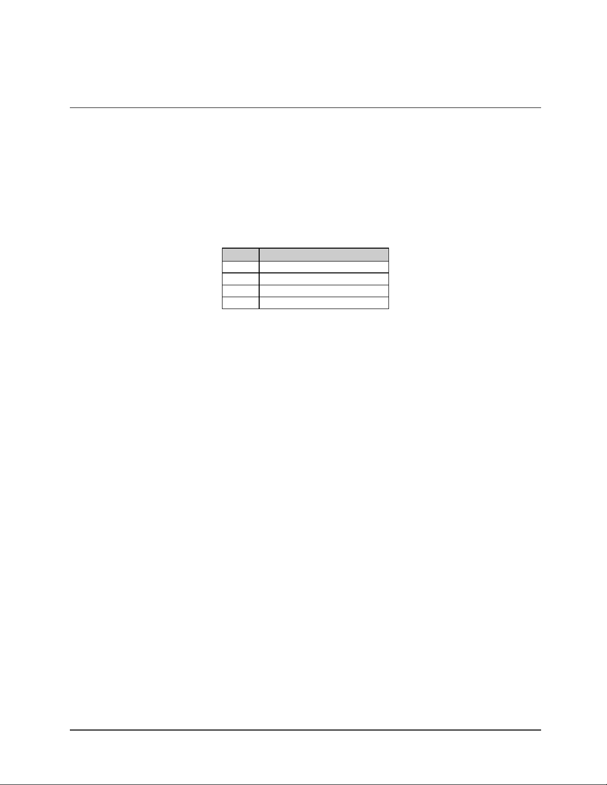
C5/K1/K3 Integrated Satellite Terminal System Specifications
2.3 Bit Error Rate Performance
Note: The following BER performance data applies to the C-Band and Ku-Band units.
Table 2-18 through Table 2-21 list the Bit Energy-to-Noise Ratio (E
achieve 10
-3
to 10
-10
BER.
Refer to Table 2-17 for BER performance curves for various options.
Table 2-17. BER Performance
Table Option
2-18 Viterbi Decoder
2-19 Viterbi and Reed-S olomon
2-20 56 kbit/s Sequential Decoder
2-21 1544 kbit/s Sequential Decoder
) required to
b/N0
Rev. 0 2–27
Page 62

Specifications C5/K1/K3 Integrated Satellite Terminal System
2.3.1 Performance with Noise and Viterbi Decoder
Refer to Table 2-18 for noise and Viterbi decoder BER.
Refer to Figure 2-1.
Table 2-18. Noise and Viterbi Decoder
Eb/N0 (dB) Specification
BER 1/2 Rate 3/4 Rate 7/8 Rate
-3
10
10
10
10
10
10
-4
-5
-6
-7
-8
3.8 4.9 6.1
4.6 5.7 6.9
5.3 6.4 7.6
6.0 7.2 8.3
6.6 7.9 8.9
7.2 8.5 9.6
2–28 Rev. 0
Page 63

C5/K1/K3 Integrated Satellite Terminal System Specifications
0
2
-
10
Performance
Noise and Viterbi Decoder
-3
10
-4
10
-5
10
-6
10
BER
-7
10
-8
10
-9
10
-10
10
3.0 4.0 5.0 6.0
Figure 2-1. Performance with Noise and Viterbi Decoder
1/2 Rate
3/4 Rate
7/8 Rate
7.0 8.0 9.0 10.0 11.
Eb/N0 (dB)
Rev. 0 2–29
Page 64

Specifications C5/K1/K3 Integrated Satellite Terminal System
2.3.2 Performance with Noise, Viterbi Decoder, and Reed-Solomon (Optional)
Refer to Table 2-19 for noise, Viterbi decoder, and Reed-Solomon BER.
Refer to Figure 2-2.
Table 2-19. Noise, Viterbi Decoder, and Reed-Solomon
Eb/N0 (dB) Specification
BER 1/2 Rate 3/4 Rate 7/8 Rate
-6
10
10
10
10
-7
-8
-10
4.1 5.6 6.7
4.2 5.8 6.9
4.4 6.0 7.1
5.0 6.3 7.5
2–30 Rev. 0
Page 65

C5/K1/K3 Integrated Satellite Terminal System Specifications
-2
10
-3
10
Performance
Noise, Viterb i Decod er, and Reed-Solomon
-4
10
-5
10
-6
10
BER
-7
10
-8
10
-9
10
-10
10
3.0 4.0 5.0 6.0
Figure 2-2. Performance with Noise, Viterbi Decoder, and Reed-Solomon
3/4 Rate
7.0 8.0 9.0 10.0 11.0
Eb/N0 (dB)
Rev. 0 2–31
Page 66

Specifications C5/K1/K3 Integrated Satellite Terminal System
2.3.3 Performance with Noise, 56 kbit/s, and Sequential Decoder (Optional)
Refer to Table 2-20 for noise, 56 kbit/s, Sequential decoder BER.
Refer to Figure 2-3.
Table 2-20. Noise, 56 kbit/s, and Sequential Decoder
Eb/N0 (dB) Specification
BER 1/2 Rate 3/4 Rate 7/8 Rate
-3
10
10
10
10
10
10
-4
-5
-6
-7
-8
4.1 5.1 6.1
4.5 5.5 6.6
5.0 5.9 7.3
5.4 6.4 7.8
5.8 6.8 8.4
4.6 5.5
2–32 Rev. 0
Page 67

C5/K1/K3 Integrated Satellite Terminal System Specifications
-2
10
Performance
Noise, 56 kbit/s, and Sequential Decoder
-3
10
-4
10
-5
10
-6
10
BER
-7
10
-8
10
-9
10
-10
10
3.0 4.0 5.0 6.0
Figure 2-3. Performance with Noise, 56 kbit/s, and Sequential Decoder
7.0 8.0 9.0 10.0 11.0
Eb/N0 (dB)
Rev. 0 2–33
Page 68

Specifications C5/K1/K3 Integrated Satellite Terminal System
2.3.4 Performance with Noise, 1544 kbit/s, and Sequential Decoder
Refer to Table 2-21 for noise, 1544 kbit/s, sequential decoder BER.
Refer to Figure 2-4.
Table 2-21. Noise, 1544 kbit/s, and Sequential Decoder
Eb/N0 (dB) Specification
BER 1/2 Rate 3/4 Rate 7/8 Rate
-3
10
10
10
10
10
10
-4
-5
-6
-7
-8
4.8 5.2 6.0
5.2 5.7 6.4
5.6 6.1 6.9
5.9 6.5 7.4
6.3 7.0 7.9
6.7 7.4 8.4
2–34 Rev. 0
Page 69

C5/K1/K3 Integrated Satellite Terminal System Specifications
-2
10
Performance
Noise, 1544 kbit/s, and Sequential Decoder
-3
10
-4
10
-5
10
-6
10
BER
-7
10
-8
10
-9
10
-10
10
3.0 4.0 5.0 6.0
Figure 2-4. Performance with Noise, 1544 kbit/s, and Sequential Decoder
3/4 Rate 7/8 Rate
7.0 8.0 9.0 10.0 11.0
Eb/N0 (dB)
Rev. 0 2–35
Page 70

Specifications C5/K1/K3 Integrated Satellite Terminal System
2.4 Acquisition Times
Refer to Table 2-22 for acquisition times.
Table 2-22. Acquisition Times
Viterbi
6 dB Eb/N0 with
Code Rate Data Rate Tacq P (t < Tacq)
1/2 < 9.6 kbit/s < 10 sec 95%
1/2
1/2
1/2
1/2
1/2
6 dB Eb/N0 with
Code Rate Data Rate Tacq P (t < Tacq)
1/2 2.4 < 4.8 kbit/s < 20 sec 95%
1/2
1/2
1/2
1/2
1/2
1/2
9.6 < 64 kbit/s
#
64 < 196 kbit/s
#
196 < 512 kbit/s
#
512 < 1000 kbit/s
#
1 < 2.5 Mbit/s
#
4.8 < 9.6 kbit/s
#
9.6 < 64 kbit/s
#
64 < 196 kbit/s
#
196 < 512 kbit/s
#
512 < 1000 kbit/s
#
1 < 2.5 Mbit/s
#
35 kHz frequency Uncertainty
< 5 sec 95%
< 1 sec 95%
< 10 sec 95%
< 2.5 sec 95%
< 1 sec 95%
Sequential
35 kHz frequency Uncertainty
< 10 sec 95%
< 5 sec 95%
< 1 sec 95%
< 17 sec 95%
< 2.5 sec 95%
<1 sec 95%
2.4.1 Receive IF Carrier Acquisition Range
The terminal will automatically lock to a correctly formatted carrier, which is within
35 kHz of the display receive frequency.
2.4.2 AGC Output (IDU)
A programmable DC output, proportional to the IDU receive signal level is located at the
rear of the panel at 10 mA maximum, 0 to 10V. Default levels are 0v for minimum signal
condition, and 10V for maximum signal condition. The low level can be programmable
from 10 to 0V in 0.1V increments.
2–36 Rev. 0
Page 71

C5/K1/K3 Integrated Satellite Terminal System Specifications
2.4.3 APS Output (ODU)
The Antenna Pointing System (APS) output on the ODU has DC output as follows:
1. Before the demodulator locks to the desired carrier, the output toggles from
0 to +5 VDC at approximately a 0.5 Hz rate.
2. After the demodulator acquires the carri er, the outp ut var ies from 0 to +5 VDC,
proportional to the receive input signal level into the IDU.
Rev. 0 2–37
Page 72

Specifications C5/K1/K3 Integrated Satellite Terminal System
2.5 Interface Specifications
2.5.1 Clock
2.5.1.1 Transmit Clock Source
The transmit clock can be selected by the operator from the following sources:
(
Terrestrial: Must be % 100 PPM of the programmed rate.
(
SCT (Internal): % 0.01 PPM.
2.5.1.2 Send Clock Timing Source
The send clock timing source output can be generated from the following sources:
(
Internal
(
External
(
Loop Timed
If loop timing is selected, the send clock timing output can be:
(
External: Must be % 100 PPM of the selected data rate.
(
Receive Satellite Clock: Data rate must be % 100 PPM of the transmit data rate.
If the asymmetrical clock loop option (ASLT) is selected, the send clock timing output can
be:
(
External clock, which can be any multiple of 8 kHz as long as it, is # 32 kHz and
" 4.3.76 MHz, or any multiple of 600 Hz as long as it is # 2.4 kHz and " 64 kHz.
(
Receive clock, which can be any multiple of 8 kHz as long as it is # 32 kHz and
" 4.376 MHz or any multiple of 600 Hz as long as it is # 2.4 kHz and " 64 kHz.
2–38 Rev. 0
Page 73

C5/K1/K3 Integrated Satellite Terminal System Specifications
2.5.1.3 Transmit Clock Switching Due to Failure of Selected Clock
The terminal will automatically switch the transmit clock source to SCT internal on failure
of terminal timing.
2.5.1.4 Transmit Clock Phase Adjustment
The transmit clock phase can be set by the operator to NORMAL, INVERTED, or AUTO
mode.
2.5.1.5 Transmit Data Phase Adjustment
The transmit data phase can be set by the operator to NORMAL or INVERTED.
2.5.1.6 Doppler Buffer Clock Source
The Doppler/plesiochronous buffer clock can be selected by the operator from the
following sources:
Receive Clock
Transmit Terrestrial
Clock
External Clock
SCT (Internal)
Must be within % 100 PPM of the nominal receive data rate. Or i t can be
any multiple of 8 kHz as long as it is # 64 kHz but " 4.376 MHz or any
multiple of 8 kHz or 600 Hz as long as it is # 32 kHz and < 64 kHz, or
any multiple of 600 Hz as it is # 2.4 kHz but " 32 kHz.
Must be within % 100 PPM of the nominal. Or it can be any multiple of
8 kHz as long as it is # 32 kHz but " 4.376 MHz or any multiple of
600 Hz as long as it # 2.4 kHz but " 32 kHz.
0.01 PPM
%
2.5.1.7 Receive Clock Switching Due to Failure of Selected Clock
The terminal will automatically switch the receive clock source to receive satellite on
failure of the selected clock.
Rev. 0 2–39
Page 74

Specifications C5/K1/K3 Integrated Satellite Terminal System
2.5.1.8 Receive Clock Phase Adjustment
The receive clock phase can be set by the operator to NORMAL or INVERTED.
2.5.1.9 Receive Data Phase Adjustment
The receive data phase can be set by the operator to NORMAL or INVERTED.
2.5.1.10 Receive Clock Jitter
The receiver has a clock jitter gain of < 2.0 dB. The absolute jitter on the output clock is
Eb/N0.
< 4% RMS of 1/data rate at 7.0 dB
2.5.1.11 Receive Doppler/Plesiochronous Buffer
The receive Doppler buffer can be configured by the operator to the following modes:
1. Bypass (Buffer set to minimum depth for emulation of previous products).
2. Selectable: 32 to 262,144 bits, in 16 bit steps.
3. Selectable: 0 to 50 ms, in 1 ms steps.
4. When running framed data, the buffer will slip in configured plesiochronous steps.
2.5.1.12 Buffering Center
The operator can set the buffer to 50%. The modem will automatically set the buffer to
50% after receive signal acquisition or a buffer overflow/underflow.
2–40 Rev. 0
Page 75

C5/K1/K3 Integrated Satellite Terminal System Specifications
2.5.1.13 Loopback Modes
The operator can select one of the following interface loopback test modes:
(
Baseband: Near end and far end.
(
Interface: Near end and far end (only available with either the Reed-Solomon or
ASYNC/AUPC daughter card installed).
2.5.1.14 Fault Outputs
Modulator Fault Open collector output, 15V maximum, 20 mA maximum
current sink, fault is open circuit.
Demodulator Fault Open collector output, 15V maximum, 20 mA maximum
current sink, fault is open circuit.
2.5.2 Terrestrial Interface Types
2.5.2.1 Universal
The following electrical interface types are available through the EIA-530, 25-pin D data
I/O connector:
(
EIA-232
(
V.35
(
EIA-422
Optional mechanical interfaces also are available. See Chapter 3 for pinout data on the
following connectors:
(
37-pin D (EIA-449)
(
34-pin Block (V.35)
(
50-pin D
ASYNC/AUPC interfaces are available through the optional 50-pin data I/O connector. In
order to satisfy the mechanical specification, the correct breakout panel must be connected
to the modem.
Rev. 0 2–41
Page 76
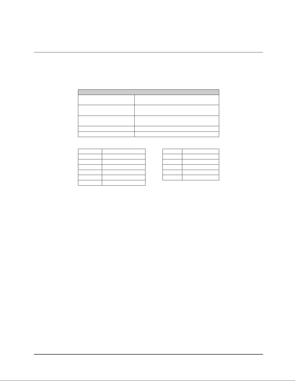
Specifications C5/K1/K3 Integrated Satellite Terminal System
2.5.2.2 EIA-232 Specification
Refer to Table 2-23 for EIA-232 specifications.
Table 2-23. EIA-232 Specifications
EIA-232 Specifi c a t ion
Circuit Supported TXD, TXC, RSD, RXC, DSR, DCD, CTS,
LL, RTS, MC, ST
Driver Amplitude (RXD,
RXC, ST, CTS, DCD, DSR)
Receiver Amplitude (TXD,
TXC, RTS, LL, MC)
Impedance
Data Rate 9.6 to 120 kbit/s
TXD Send Data LL Local Loopback
RXD Receive Data ST Send Timing
RTS Request to Send RX C Receive Timing
CTS Clear to Send TXC Terminal Timing
DCD Carrier Detect MF MOD Fault
DSR Receiver Ready DF DEMOD Fault
MC Master Clock
True: 10V % 5V
False: -10V % 5V
True: Minimum +1V
False: Maximum –1V
5000 % 2000! < 2500pF
2–42 Rev. 0
Page 77

C5/K1/K3 Integrated Satellite Terminal System Specifications
2.5.2.3 V.35 Specification V.10, V.11 Specification, Circuit Supported
Refer to Table 2-24 for V.35 specifications.
Table 2-24. V.35 Specifications
V.35 Specification
Circuit Supported SD, SCT, SCTE, RD, SCR, DSR, RLSR, RTS, CTS, MC, DSR,
LL
Driver Amplitude (RD, SCR,
SCTE, CTS, RLSD, DSR)
Amplitude (SCT, SD, RTS, LL,
MC)
Polarity (SD, SCT, SCTE, RD,
SCR)
Polarity (RTS, CTS, DSR,
RLSD)
Phasing (SCTE, SCR) False-to-True transition nominally in center of data bit.
Symmetry (SCT, SCTE, SCR)
0.5V-PK, % 20% differential, into 100
%
0.2V min into 100
%
True when B positive with respect to A
False when A positive with respect to B
True when < -0.2v with respect to ground
False when > +0.2V with resp ect to ground
50% % 5%
!
!
SD-A, SD-B Send Data
SCT-A, SCT-B Serial Clock Transmit
RD-A, RD-B Receive Data
SCR-A, SCR-B Serial Clock Receive
SCTE-A, SCTE-B Transmiss ion Signal Timing
MC-A, MC-B Master Clock
RTS Request to Send
CTS Clear to Send
DSR Data Set Ready
RLSD Receive Line S ignal Detect
LL Local Loopback
MF MOD Fault (ttl)
DF DEMOD Fault (ttl)
Note: All other specifications are per CCITT V.10 and V.11.
Rev. 0 2–43
Page 78

Specifications C5/K1/K3 Integrated Satellite Terminal System
2.5.2.4 EIA-449/EIA-422 Specifications
Refer to Table 2-25 for EIA-449/EIA-422 specifications.
Table 2-25. EIA-449/EIA-422 Specifications
EIA-449/EIA-422 Specification
Circuit Supported SD, ST, TT, RD, RT, DM, RR, RS, CS, MC
Amplitude (RD, RT, ST, DM,
RR)
Impedance (SD, TT, MC)
Phasing (RD, RT) False-to-True transition of RT nominally in center of RD data
Symmetry (ST, TT, RT)
SD-A, SD-B Send Data
ST-A, ST-B Send Timing
RD-A, RD-B Receive Data
RS-A, RS-B Request to Send
RT-A, RT-B Receiv e Timing
CS-A, CS-B Clear to Send
DM-A, DM-B Data Mode
RR-A, RR-B Receiver Ready
TT-A, TT-B Terminal Timing
MC-A, MC-B Master Clock
MF MOD Fault (ttl)
DF DEMOD F ault (ttl)
2V differential into 100
%
4k
!
True when B positive with respect to A
False when A positive with respect to B
bit.
50% % 5%
!
2–44 Rev. 0
Page 79

C5/K1/K3 Integrated Satellite Terminal System Specifications
2.5.3 Asynchronous Overhead Specification (Optional)
The operator can select EIA-232 or EIA-485 for either the transmit or receive
asynchronous overhead data type.
Refer to Table 2-26 for asynchronous specifications.
Table 2-26. Asynchronous Specifications
Primary Data Rates Supported
Interfaces:
EIA-422
V.35
EIA-232
Maximum Data Rate 1.875% of primary channel
Channel Interface EIA-232
Connector 25-pin D on breakout panel (UB300)
Available Baud Rates 110, 150, 300, 600, 1200, 2400, 4800, 9600, 19200, 38400, bit/s
Protocol Format 5, 6, 7, 8 data bits
Circuits Supported SD, RD, RTS, CTS
Amplitude (RD, RTS)
Amplitude (TD, DSR,
CTS)
Impedance
Baud Rate 1/512 times the primary data rate
Target Power Levels C-Band: +25 to +38 dBm
Target Eb/N0 Level 3.2 to 16.0 dB, in 01 dB steps
Tracking Rate 0.5 to 6.0 dB/min, in 0.5 dB/min steps
Local/Remote Carrier
Loss Setting (Local Has
Priority)
9.6 kbit/s, 19.2 kbit/s, 32 kbit/s to 2.048 Mbit/s
9.6 kbit/s, 19.2 kbit/s, 32 kbit/s to 2.048 Mbit/s
9.6 to 120 kbit/s
Asynchronous ESC
EIA-485 (2-Wire) Half-Duplex
EIA-485 (4-Wire) Full-Duplex
Even, Odd, No Parity
1 or 2 stop bits ( 1 or 1.5 for 5 bit)
EIA-232 Specifi c a t ions
True: 14V % 11V
False: -14V % 11V
True: 11V % 2V
False: -11V % 2V
5000 % 2000! < 2500 pF
AUPC Specifications
Ku-Band K1: +17 to +30 dBm
Ku-Band K3: +22 to +35 dBm
Maximum – go to highest power output level
Nominal – go to preprogrammed output level
Hold – No action
Note: Local carrier loss has priority over remote carrier loss.
AUPC Test Modes 2047 test pattern for remote BER monitoring
Remote baseband loopback test
Rev. 0 2–45
Page 80

Specifications C5/K1/K3 Integrated Satellite Terminal System
2.5.3.1 Local Automatic Uplink Power Control (AUPC)
AUPC functions are available with ASYNC interface. The operator can select local AUPC
to be enabled or disabled.
Eb/N0 target setpoint from 3.2 to 16.0 dB in 0.1 dBm steps.
The operator can select the
2.5.3.2 Remote AUPC
1. The operator can select remote AUPC to be enabled or disabled.
2. The operator can select a remote TX 2047 test pattern and a remote baseband
loopback to be enabled or disabled.
3. The operator can monitor the remote AUPC 2047 BER.
2–46 Rev. 0
Page 81

C5/K1/K3 Integrated Satellite Terminal System Specifications
2.6 System Specifications
2.6.1 Test Modes
Refer to Table 2-27 for available test modes.
Table 2-27. Test Modes
Test Mode Description
RF Loopback Tunes the RX frequency to the satellite downlink frequency for the
configured TX frequency. A C-Band system will tune the RX frequency
2.225 GHz below the TX frequency. A Ku-Band system will tune the RX
frequency 2.3 GHz below the TX frequency.
Note:
The TX and RX data rates must be the same for the modem to lock.
IF Loopback Tunes the RX IF to a sample of the TX IF output. The IF out is not
affected.
Notes:
1. The TX and RX data rates must be the same for the modem to
lock.
2. Since the TX IF output is active, RF OFF must be selected if
transmission is not intended.
BIST (Built in
Self Test)
RS CORR Off Turns off the Reed-Solomon decoder data error correction circuitry. Data
Baseband
Loopback
2047 Pattern
Generator
Interface
Loopback
2047 Pattern
Monitor
The IDU has the ability to generate 211-1 (2047) PN data and pass the
data through the interface, modulator, and demodulator sections of the
IDU. The IDU generates noise in the IF path to simulate a satellite
environment. This feature invokes on power up or by the operator and the
result checked against specification (and a fault is flagged if the unit
fails). This feature can be turned off at the front panel (if desired) to
minimize initialization time.
flow is then routed through the normal data paths without error
correction.
Note:
Available with Reed-Solo mon Int erface only.
Internally switches the modulator clock and data signals to the
demodulator. Also, loops the external DTE TX clock and data to the
external receiver.
Inserts an industry standard 2047 patt ern i n place of the TX data stream.
Note:
Available with Overhead card i nstalled.
Internally switches the modulator clock and data (with overhead data)
signals to the demodulator. Also, loops the external DTE TX clock and
data to the external DTE receiver.
Note:
Available with Overhead or Reed-Solomon option installed.
Monitors the RX data for 2047 pattern. If 2047 pattern is present; this test
mode provides an indication of Bit Error Rate (BER). The RX data is not
interrupted.
Note:
Available with Overhead card i nstalled.
ODU Enable Disables ODU faults and alarms.
Rev. 0 2–47
Page 82

Specifications C5/K1/K3 Integrated Satellite Terminal System
2.6.2 Remote Control
All terminal functions are controlled remotely through the remote connector on the rear
panel. Refer to Appendix B for the Remote Control Specification. Refer to Table 2-28 for
functions controlled.
Table 2-28. Remote Control Functions
Transmit
Digital Data Rate 2.4 kbit/s to 4.375 Mbit/s, in 1 bit steps
Code Rate BPSK 1/2
QPSK 1/2, 3/4, and 7/8
Encoder Type Viterbi
Sequential
Reed-Solomon Encoder On or Off
Transmit Frequency C-Band: 5.925 to 6.425 GHz, in 100 Hz steps
Ku-Band: 14.0 to 14.5 GHz, in 100 Hz steps
Transmit RF On or Off
Transmit Modulation Type EFD, CSC, FDC, and all closed networks
Transmit Power C-Band: +25 to +38 dBm, in 0.1 dB steps
Ku-Band K1: +17 to +30 dBm, in 0.1 dB steps
Ku-Band K3: +22 to +35 dBm, in 0.1 dB steps
Scrambler Enable On or Off
Differential Encoder On or Off
Transmit Spectrum Rotation Normal or Inverted
Transmit BPSK Bit Order Normal or Inverted
Carrier Only Mode Normal, Dual, Offset, or Center
Receive
Digital Data Rate 2.4 to 4375 kbit/s, in 1 bit steps
Code Rate BPSK 1/2
QPSK 1/2, 3/4, and 7/8
Decoder Type Viterbi or Sequential
Reed-Solomon Decoder On or Off
Receive Frequency C-Band:
3.7 to 4.2 GHz
Ku-Band:
10.95 to 11.45 GHz, in 100 Hz steps
11.2 to 11.7 GHz, in 100 Hz steps
11.7 to 12.2 GHz, in 100 Hz steps
12.25 to 12.75 GHz, in 100 Hz steps
Receive Modulation Type EFD, CSC, FDC, and all closed networks
Descrambler Enable On or Off
Differential Decoder On or Off
Receive Spectrum Rotation No rmal or Inverted
Receive BPSK Bit Order Normal or Inverted
IF Loopback On or Off
Sweep Center -35 kHz to +35 kHz, in 1 Hz steps
Sweep Width 0 to 70 kHz, in 1 Hz steps
Sweep Reacquisition 0 to 999 seconds
BERT Threshold 10-3 to 10-8 or Off
Interface
Transmit OH Type ASYNC or None
Receive OH Type ASYNC or None
Transmit Driver Type V.35, EIA-422, or EIA-232
2–48 Rev. 0
Page 83

C5/K1/K3 Integrated Satellite Terminal System Specifications
Table 2-29. Remote Control Functions (Continued)
Interface (Continued)
Receive Driver Type V.35, EIA-422, or EIA-232
Transmit Clock Internal, External, or Reference
External Clock Reference 8.0 to 10000 kHz
Receive Buffer Size 3 2 to 262144 bit/s, in 16 bit/s steps or 0 to 50 ms, in 1 ms step
Transmit Clock Phase Auto, Normal, or Inverted
Buffer Clock Internal, External, Reference, or Saturated
Receive Clock Phase Normal or Inverted
Baseband Loopback On or Off
Interface Loopback On or Off
Interface Loop Timing On or Off
Transmit Framing T1 or E1, None, or G.704
Receive Framing T1 or E1, None, or G.704
Substitute Pattern T X2047
Error Select RX2047
Transmit Coding AMI, HDB3, B8ZS
Receive Coding AMI, HDB3, B8ZS
Transmit Data Fault None, Data, AIS
Receive Data Fault None, Data, AIS
ASYNC TX Baud Rate 110 to 38400
ASYNC RX Baud Rate 110 to 38400
ASYNC TX Channel Character
Length
ASYNC RX Channel Character
Length
ASYNC TX Channel Stop Bits 1 or 2
ASYNC RX Channel Stop Bits 1 or 2
ASYNC TX Channel Parity Even, Odd, or None
ASYNC RX Channel Parity Even, Odd, or None
ASYNC TX Electrical Interface EIA-232 or EIA-485
ASYNC RX Electrical Interface EIA-232 or EIA-485
Transmit Data Phase Normal or Inverted
Receive Data Phase Normal or Inverted
CTS Time Delay 0 to 999 seconds
Reference Frequency Offset
Clear Stored Faults
Terminal Operation Mode TX, RX, Duplex
System Modem Type ASYNC, EFD, or Custom
Local AUPC Mode On or Off
RTS TX-IF Control Mode On or Off
Power (C-Band) +25 to + 38 dBm, in 0.1 dB steps
Power (Ku-Band K1) +17 to + 30 dBm, in 0.1 dB steps
Power (Ku-Band K3) +22 to + 35 dBm, in 0.1 dB steps
Eb/N0 Target 3.2 to 16.0, in 0.1 dB steps
Maximum Tracking Rate 0.5 to 6.0 dB/min, in 0.5 dB steps
Carrier Loss Action Hold, Nominal, or Maximum
5, 6, 7, or 8
5, 6, 7, or 8
System
Local AUPC
Rev. 0 2–49
Page 84

Specifications C5/K1/K3 Integrated Satellite Terminal System
2.7 Component Specifications
2.7.1 Options
Refer to Table 2-29 for options.
Table 2-29. Options
Option Remarks
Sequential or Viterbi Codec Modem can be supplied:
Viterbi only
Sequential only
Viterbi or Sequential
Reed-Solomon Codec Concatenates with Viterbi or Sequential
Asynchronous Interface Includes automatic uplink power control (AUPC)
EIA-422/449 Interface
34-pin Winchester (V.35)
Signal Data/Code Rate
512 kbit/s maximum data rate
"
5.0 Mbit/s maximum data rate
"
Asynchronous Loop Timing (SCT)
48 VDC Primary Pow er
24 VDC Primary Pow er
2–50 Rev. 0
Page 85

C5/K1/K3 Integrated Satellite Terminal System Specifications
2.7.2 SDT-5200 (IDU) System Specifications
The SDT-5200 IDU is a complete, variable-rate satellite modem, high-stability reference,
and power supply in a 1 RU package.
Refer to Table 2-30 for IDU system specifications.
Table 2-30. SDT-5200 System Specifications
Parameter Specifications
IF Output Connector Type N female
IF Input Connector Type N female
RX-AUX Connector BNC female
Data I/O Connector EIA-530, 25-pin D sub, female (EIA-422, EIA-232, and V.35)
EIA-449, 37-pin D sub, female, (EIA-422) Optional
EFD Standard, 50-pin D sub, female (ASYNC) Optional
V.35, 34-pin Winchester Optional
Alarm Connector Form C Contact, 9-pin D sub, female
Fault Connector Form C Contact, 9-pin D sub, female
Auxiliary Connector Open Collector, 9-pin D sub, female
Remote Connector EIA-232 or EIA-485, 9-pin D sub, female
Prime Power 85 to 264 VAC, 47 to 63 Hz, using a 6 foot (2 meter) cable 3-prong plug:
meets EFData QUA-014, Operating Procedures.
Power Consumption 60W maximum
Size
Weight
Mounting
Temperature
Humidity
Shock
Agency Compliance:
Safety
Emissions
Susceptibility
Warm-up Time < 30 minutes
1.75H x 19W x 17.8D inches (4.4 x 48.26 x 45.21 cm)
12 lb. maximum (5 kg)
Standard 19-inch (48.26 cm) rack. Must accept front and rear mounts and
accept standard rack mount slides.
0 to 50&C (32 to 122&F)
90% non-condensing
When any one corner of the IDU is dropped from 1 cm onto a hard
surface, the IDU will not take any errors or faults.
CE MARK – EN60950
CE MARK – EN55022-1
CE MARK – EN50082-1
Rev. 0 2–51
Page 86

Specifications C5/K1/K3 Integrated Satellite Terminal System
2.7.2.1 IDU Transmit Specification
Refer to Table 2-31 for IDU transmit specifications.
Table 2-31. IDU Transmit Specifications
Parameter Specifications
Output Frequency Range 779 to 801 MHz, in 100 Hz steps
Frequency Stability
Output Power -10 dBm (fa c tory calibrated)
Output Impedance
Output Return Loss > 12 dB
Output S/N Ratio > 50 dB
Output Phase Noise < -63 dBc/Hz at 100 Hz
Undesired Sideband Suppression < -30 dBc
Carrier Suppression < -35 dBc
Spurious < -50 dBc in any 3 kHz BW
Harmonics < -45 dBc
Output Off Level < -50 dBm
ODU Power (from center
conductor of IF Output)
ODU Reference 50 MHz at –3 dBm
ODU M&C Data Link Half Duplex, ASK Modulated serial digital data with either a 3. 68 MHz
Modulated Output Shap ing EFData Closed, Comstream Closed, Fairchild Closed
Modulation Coherent QPSK or BPSK
Symbol Rate Range (variable): 4.8 to 2500 ks/s
Data Rate Range (variable):
QPSK
BPSK
Forward Error Correction Viterbi K = 7, 1/2, 3/4, and 7/8 rate
Scrambling CCITT V.35 IESS modified, CCITT V.35 (EFD or CSC Closed), FDC,
Transmit Frequency Change
Time
0.01 ppm
%
50! % 10%
< -73 dBc/Hz at 1 kHz
< -83 dBc/Hz at 10 kHz
< -93 dBc/Hz at 100 kHz
+36 V DC (2.5A maximum), % 1 VDC
4.8 to 4375 kbit/s, in 1.0 bit/s steps
2.4 to 1250 kbit/s, in 1.0 bit/s steps
Optional: Sequential K = 36, 1/2, 3/4, 7/8 rate
Optional: Reed-Solomon IESS 308/309 Concatenated 225.205 T = 10
215-1 SYNC
< 200 ms
2–52 Rev. 0
Page 87

C5/K1/K3 Integrated Satellite Terminal System Specifications
2.7.2.2 IDU Receive Specification
Refer to Table 2-32 for IDU receive specifications.
Table 2-32. IDU Receive Specifications
Parameters Specifications
IF Input Frequency Range 950 to 1450 MHz, in 100 Hz steps
IF Input Level
Desired Signal
IF Input Composite Power:
Symbol Rate > = 64 ks/s
< = 64 ks/s
Absolute Maximum
IF Input Impedance
IF Input Return Loss
(950 to 1700 M H z)
RX-AUX Output
Baseband Filtering EFData Closed, Comstream Closed, Fairchild Closed
Demodulation Coherent QPSK or BPSK
Acquisition Range 0 kHz to 70 kHz, programmable in 100 Hz increments, range is
Symbol Rate Range (variable) 4.8 to 2500 ks/s
Data Rate Range (variable)
QPSK
BPSK
Forward Error Correction Viterbi K = 7, 1/2, 3/4, 7/8 rate
Bit Error Rate:
Viterbi 1/2 Rate
Viterbi 1/2 Rate (with Reed-
Solomon)
Ambiguity Resolution Method Differential Decoder
Descrambling CCITT V.35 IESS modified, CCITT V.35 (EFD or CSC Closed), FDC,
-135 dBm +10 log (Symbol Rate) minimum
-85 dBm +10 log (Symbol Rate) maximum
+40 dBc with respect to RX signal
+50 dBc with respect to RX signal
-5 dBm
50! % 10%
> = 10 dB at 50
!
Nominal 0 dB gain from IF Input % 3 dB
rounded to nearest multiple of the opening symbol rate
4.8 to 4375 kbit/s, in 1.0 bit/s steps
2.4 to 1250 kbit/s, in 1 bit/s steps
Optional: Sequential K = 36, 1/2, 3/4, 7/8 rate
Optional: Reed-Solomon IESS 308/309 Concatenated 225.205 T = 10
-8
for Eb/N0 7.2 dB
1 x 10
-10
1 x 10
2
for Eb/N0 5.0 dB
15
-1 SYNC
Rev. 0 2–53
Page 88

Specifications C5/K1/K3 Integrated Satellite Terminal System
2.7.3 C-Band Outdoor Unit
The C-Band ODU is mounted on the feed support arm of a wide variety of parabolic
antennas ranging from 1.2 to 3.1 meters in diameter. The ODU interfaces other
components by two coaxial cables. The C-Band LNA, OMT, and feed horn assembly are
mounted at the focus of the antenna. The ODU directly interfaces to the IDU.
Refer to Table 2-33 for C-Band ODU specifications.
Table 2-33. C-Band ODU Specifications
Parameter Specifications
Physical:
Size
Weight
Environmental:
Temperature:
Operating
Survival
See Figure 2-5 and Figure 2-6.
30 lb. maximum (13.6 kg)
-40& to +55&C (-40& to +131&F)
-50& to +80&C (-58& to +176&F)
Thermal Gradient
Humidity
Precipitation
Salt Fog
Sand and Dust
Altitude
Operating
Survival
Solar Radiation
ES Discharge
Shock
10&C/15 min (50&F/15 min)
0% to 100% relative at -40& to +55&C (-40& to +131&F)
95% at 65&C (149&F) for 72 hours
4 inch/hour with wind speed of 45 miles/hour with gusts to
50 mile/hour
810/Method 506.2
810/Method 509.2
810/Method 510.1
0 to 25,000 ft (0 to 7620 km)
0 to 50,000 ft (0 to 15,240 km)
2
360 BTU/hr/ft
10 kV operation, 15 kV survival, IEC pub 801-2
Note:
Excluding any center point of any connector.
The unit will pass data without SYNC loss at 64 kbit/s, QPSK 1/2
rate when subjected to a sho ck of 10g’s at 10 sec (half sine) on x,
y, and z axes. The unit will survive a shock of 40g’s at 10msec on
x, y, and z axes in non-operating mode.
at +50&C (122&F)
Note:
Without mounting cradle.
2–54 Rev. 0
Page 89

C5/K1/K3 Integrated Satellite Terminal System Specifications
Table 2-34. C-Band ODU Specifications (Continued)
Parameter Specifications
Environmental:
Vibration
The unit will pass data without SYNC loss at 64 kbit/s, QPSK 1/2
rate when exposed to 10 minutes per axis plus 5 minute resonant
dwell at four major resonance’s per axis at a level of 1.0g
(0-Peak), and to 2.41 G
(approx.) of random vibration specified
rms
as follows:
Interfaces:
TX IF Input
RX IF Output
APS Output
TX Output
RX Input
Frequency Slope
PSD
5 to 100 Hz 0 0.020 g2/Hz
100 to 137 Hz -6 dB/oct 137 to 350 Hz 0 0.0107 g2/Hz
350 to 500 Hz -6 dB/oct 500 Hz - 0.0052g2/Hz
The unit will survive vibration during transportation as follows:
5 to 200 Hz at 1.5 peak sinusoidal acceleration in shi pping
container.
Type N Female
Type N Female
Type N Female, with chained waterproof cap
Type N Female
Type N Female
Rev. 0 2–55
Page 90

Specifications C5/K1/K3 Integrated Satellite Terminal System
2.7.4 Ku-Band Outdoor Unit
The ODU accepts a 790 % 11 MHz TX IF signal, and transmits the signal in the 14.0 to
14.5 GHz frequency band. The maximum available transmit power is +29 dBm (P1dB) or
+34 dBm (P1dB) depending on the option selected. Output power level is controlled by an
ALC loop to provide extremely stable output power regardless of temperatures variations.
Refer to Table 2-34 for Ku-Band ODU specifications.
Table 2-34. Ku-Band ODU Specifications
Parameter Specifications
K1 (0.8W)
Size
Weight
K3 (2.5W)
Size
Weight
Environmental:
Temperature:
Operating
Survival
See Figure 2-7.
12 lbs (5 kg) maximum
See Figure 2-7.
22 lbs (9.98 kg), includes cradle maximum
-40& to +55&C (-40& to +131&F)
-50& to +80&C (-58& to +176&F)
Thermal Gradient
Humidity
Precipitation
Salt Fog
Sand and Dust
Altitude
Operating
Survival
Solar Radiation
ES Discharge
10&C/15 min (50&F/15 min)
0% to 100% relative at -40& to +55&C (-40& to +131&F)
95% at 65&C (149&F) for 72 hours
4 inch/hour with wind speed of 45 miles/hour with gusts to
50 mile/hour
810/Method 506.2
810/Method 509.2
810/Method 510.1
0 to 25,000 ft (0 to 7620 km)
0 to 50,000 ft (0 to 15,240 km)
360 BTU/hr/ft
10 kV operation, 15 kV survival, IEC pub 801-2
Note:
Excluding any center point of any connector.
2
at +50&C (122&F)
2–56 Rev. 0
Page 91

C5/K1/K3 Integrated Satellite Terminal System Specifications
Table 2-35. Ku-Band ODU Specifications (Continued)
Parameter Specifications
Environmental:
Shock
Vibration The unit will pass data without SYNC loss at 64 kbit/s, QPSK 1/2 rate
The unit will pass data without SYNC loss at 64 kbit/s, QPSK 1/2 rate
when subjected to a shock of 10g’s at 10 sec (half sine) on x, y, and z
axes. The unit will survive a shock of 40g’s at 10msec on x, y, and z
axes in non-operating mode.
Note:
Without mounting cradle.
when exposed to 10 minutes per axis plus 5 minute resonant dwell at
four major resonance’s per axis at a level of 1.0g (0-Peak), and to
2.41 G
(approx.) of random vibration specified as follows:
rms
Frequency Slope
PSD
5 to 100 Hz 0 0.020 g2/Hz
100 to 137 Hz -6 dB/oct 137 to 350 Hz 0 0.0107 g
2
/Hz
350 to 500 Hz -6 dB/oct 500 Hz - 0.0052g2/Hz
The unit will survive vibration during transportation as follows:
5 to 200 Hz at 1.5 peak sinu soidal acceleration in shipping container.
Rev. 0 2–57
Page 92
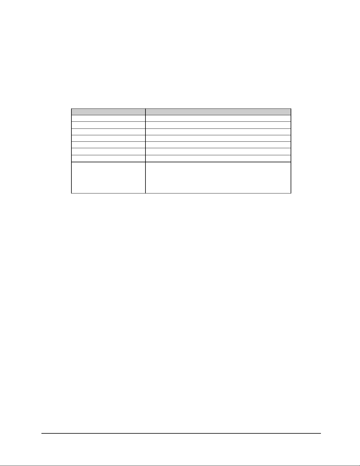
Specifications C5/K1/K3 Integrated Satellite Terminal System
2.7.5 C-Band LNA Specifications
Refer to Table 2-35 for C-Band LNA specifications
Table 2-35. C-Band LNA Specifications
Parameter Specifications
Gain 44 to 52 dB (over the full ba nd a nd ope ra ting temperature range)
1 dB Gain Compression Point
RF Input W/G CPR-229 G
Input Power +12 to +18 VDC at 120 m A maximum
Frequency Band 3.7 to 4.2 GHz
Output Connector
Noise Temperature
Particulars:
Operating Temperature
Size
Weight
0 dBm
"
Type N female, 50
60&K at 25&C (77&F)
'
-40& to +55&C (-40 & to +131&F)
2W x 8D x 2H inches (approx.)
(5 W x 20 D x 5 W cm )
< 2 lb. (< 0.9 kg)
!
2–58 Rev. 0
Page 93

C5/K1/K3 Integrated Satellite Terminal System Specifications
This page is intentionally left blank.
Rev. 0 2–59
Page 94

Specifications C5/K1/K3 Integrated Satellite Terminal System
14.0
2.8 Dimensional Envelopes
2.8.1 SDT-5200 Dimensional Envelope
Refer to Figure 2-5 for the dimensional envelope.
Note: All dimensions are in English units, centimeters are in parentheses.
19.0
(48)
1.75
(4.4)
(36)
SDT-5200
1.25
(3.2)
3.0
(8)
3.625
(9.2)
3.625
(9.2)
Figure 2-5. SDT-5200 Dimensional Envelope
2–60 Rev. 0
Page 95

C5/K1/K3 Integrated Satellite Terminal System Specifications
TYPE
N
FEMALE
2.8.2 C-Band Outdoor Unit (ODU) Dimensional Envelope
Refer to Figure 2-6 for C-Band ODU dimensional envelope.
RX-IF
TYPE N FEMALE
CAP
LABEL
25 in.
(63.5)
APS
TYPE N FEMALE
TX-IF
TYPE N FEMALE
22 IN.
(55.88)
MOUNTING BRACKET
9.5 IN
(24.13)
Figure 2-6. C-Band ODU Dimensional Envelope
(20.32)
8
IN.
Rev. 0 2–61
Page 96

Specifications C5/K1/K3 Integrated Satellite Terminal System
DIM
A
2.8.3 Ku-Band Outdoor Unit Dimensional Envelope
Refer to Figure 2-7 for Ku-Band ODU dimensional envelope.
(TX-IF)
TYPE N FEMALE
-90
ATP
RX TX
+90
(RX-IF)
TYPE N FEMALE
RX E-POLE
(RX-IF)
ANGLE SCALE
POLARIZATION
TYPE N FEMALE
DIM B
(20.32)
8 IN
DEPTH 12
6-No. 6-32 UNC
6.5 IN
(24.13)
AB
K1 K1K3 K3
12 IN 12 IN16 IN 15 IN
(30.48) (30.48)(40.64) (38.10)
Figure 2-7. Ku-Band ODU Dimensional Envelope
2–62 Rev. 0
Page 97

This chapter provides installation and mounting instructions for the Satellite Terminal
System.
3.1 Unpacking
The Satellite Terminal System and manual are packaged in pre-formed, reusable,
cardboard cartons containing foam spacing for maximum shipping protection.
Do not use any cutting tool that will extend more than 1 inch (2.5 cm) into
the container. This can cause damage to the modem.
CAUTION
Chapter 3.
INSTALLATION
3
Unpack the Satellite Terminal System as follows:
1. Cut the tape at the top of the carton indicated by OPEN THIS END.
2. Remove the cardboard/foam space covering the unit.
3. Remove the unit, manual, and power cord from the carton.
4. Save the packing material for storage or reshipment purposes.
5. Inspect the equipment for any possible damage incurred during shipment.
6. Check the equipment against the packing list to ensure the shipment is correct.
Rev. 0 3–1
Page 98

Installation C5/K1/K3 Integrated Satellite Terminal System
3.2 Equipment Inspection
3.2.1 Included Parts
A typical Satellite Terminal System contains the following components:
Notes:
1. Parts are not drawn to scale.
2. Because each installation can be customized, this manual will provide
instructions for installing the universal mounting kit.
Qty. Description Qty. Description
1 C-Band Satellite Terminal System Compone nts 1 Ku-Band Satellite Term ina l System Compone nts
1 Installation and Operation Manual 2 Cable Ass e mbly (See 3.2.1.1)
(Optional)
1 Envelope containing the test da ta
3–2 Rev. 0
Page 99

C5/K1/K3 Integrated Satellite Terminal System Installation
3.2.1.1 Cable Assembly (Customer-Furnished)
EFData recommends the use of a high-performance cable assembly for the
Satellite Terminal System. A non-high-performance cable assembly may
CAUTION
The Satellite Terminal System is manufactured to accommodate a transmit attenuation of
20 dB maximum between the IDU and the ODU, and a receive attenuation of 25 dB
maximum between the IDU and receive LNA. The optional IFL cable assembly offered
by EFData is a high-performance cable selected to accommodate the attenuation of the
unit’s IFL losses incurred up to 300 metric feet, maximum.
Refer to the following for cable characteristics:
result in damage to the LNA.
!
Double shielded: > 90 dB
!
Bend Radius: "1 inch
!
TX 2# maximum
!
Temperature Range: -40$ to +85$C (-40$ to +185$F)
!
Rugged construction, weather sealed.
!
RX 5# maximum
Rev. 0 3–3
Page 100

Installation C5/K1/K3 Integrated Satellite Terminal System
Tools Required
Note: Equivalent substitutes may be used for listed items.
Qty. Description
1
3/8” drive ratchet.
1
3” x 3/8” drive ex tens ion.
1
5/16” x 3/8” drive sock e t. (Me t ric e quiv a le nt: 8 x 9mm)
1
1/4” x 3/8” drive sock e t. (Me tr ic e quiv a lent: 6 x 9mm)
1 5/16” combination wrench.
with a 6 pt. Box end.)
1 1/4” combination wrench.
with a 6 pt. Box end.)
(Metric equivalent: 8mm combination wrench
(Metric equivalent: 6mm combination wrench
3–4 Rev. 0
 Loading...