

Page 1

Compaq Armada M300
Series of Personal Computers
Reference Guide
Page 2

D
OCUMENTATION
Thank you for choosing Compaq!
Please help us provide quality support information by completing and
returning this postage-paid questionnaire.
1. Were you able to set up the computer using the setup poster?
❏ Yes ❏ No If not, at what point did you begin to have difficulty?
2. Was the Quick Reference Guide preinstalled on your computer easy to find? ❏ Yes ❏ No
Is it easy to use? ❏ Yes ❏ No If not, why?
3. What computer task(s) will you need the most help with?
4. If you need help with a computer task, where will you get it?
5. Which do you prefer?
❏ Quick Reference Guide preinstalled on computer
❏ Printed Reference Guide ❏ Both
Why?
6. In addition to a printed Reference Guide, how else would you prefer to receive your
information?
Rank 1 to 4 (1 is most preferred)
Preinstalled on computer
On CD-ROM
On Compaq web site
None of above
Additional Documentation Comments:
S
URVEY
Note: For comments not related to documentation, call
1-800-345-1518 (U.S.) or 1-800-567-1616 (Canada).
Name
Occupation
Company Phone No.
Street Address
City State Zip
Compaq Armada M300 Series
Page 3
Perf
Tape Please do not staple Tape
Perf
Fold Here
BUSINESS REPLY MAIL
FIRST-CLASS MAIL PERMIT NO. 400 HOUSTON, TX
POSTAGE WILL BE PAID BY ADDRESSEE
COMPAQ COMPUTER CORPORATION
ATTN: Portable PC Marketing Comm.
Emily Perlman, MC 130805
P O BOX 692000
HOUSTON TX 77269-9976
NO POSTAGE
NECESSARY
IF MAILED
IN THE
UNITED STATES
Tear here and mail
Perf
Page 4

Compaq Armada M300 Series
Reference Guide
First Edition (June 1999)
Part Number 113733-001
Compaq Computer Corporation
Page 5

Notice
The information in this publication is subject to change without notice.
COMPAQ COMPUTER CORPORATION SHALL NOT BE LIABLE FOR TECHNICAL OR
EDITORIAL ERRORS OR OMISSIONS CONTAINED HEREIN, NOR FOR INCIDENTAL OR
CONSEQUENTIAL DAMAGES RESULTING FROM THE FURNISHING, PERFORMANCE, OR
USE OF THIS MATERIAL. THIS INFORMATION IS PROVIDED “AS IS,” AND COMPAQ
COMPUTER CORPORATION DISCLAIMS ANY WARRANTIES, EXPRESS, IMPLIED, OR
STATUTORY, AND EXPRESSLY DISCLAIMS THE IMPLIED WARRANTIES OF
MERCHANTABILITY, FITNESS FOR PARTICULAR PURPOSE, GOOD TITLE, AND AGAINST
INFRINGEMENT.
This publication contains information protected by copyright. No part of this publication may be
photocopied or reproduced in any form without prior written consent from Compaq Computer
Corporation.
1999 Compaq Computer Corporation. All rights reserved. Printed in Singapore.
The software described in this guide is furnished under a license agreement or nondisclosure agreement.
The software may be used or copied only in accordance with the terms of the agreement.
Compaq, Armada, Compaq Insight Manager, ROMPaq, and PaqFax are registered U. S. Patent and
Trademark Office.
SoftPaq, QuickBlank, and QuickLock are trademarks and/or service marks of Compaq Computer
Corporation.
Microsoft, MS-DOS, Windows, and Windows NT are registered trademarks of Microsoft Corporation.
Imation and SuperDisk are trademarks of Imation Enterprises Corporation.
Phoenix is a registered trademark of Phoneix Technologies Ltd. MultiBoot is a trademark of
Phoenix Ltd.
Other product names mentioned herein may be trademarks and/or registered trademarks of their
respective companies.
Compaq Armada M300 Series Reference Guide
First Edition (June 1999)
Part Number 113733-001
iv
Page 6

Contents
About This Guide
Text Conventions..................................................................................................................... xiii
Symbols in Text.......................................................................................................................xiv
Chapter 1
Getting Started
Finding Information................................................................................................................. 1-1
Identifying Packing Box Contents............................................................................................1-1
Chapter 2
Taking a Look at the Computer
Top Components......................................................................................................................2-1
Left Side Components.............................................................................................................. 2-3
Right Side Components............................................................................................................2-4
Front Components.................................................................................................................... 2-5
Rear Components.....................................................................................................................2-6
Bottom Components.................................................................................................................2-7
External Diskette Drive............................................................................................................ 2-8
Connecting the Diskette Drive..........................................................................................2-8
Disconnecting the Diskette Drive .....................................................................................2-8
Versatile Battery Pack.............................................................................................................. 2-9
v
Chapter 3
Using the Keyboard
Using the Pointing Device........................................................................................................3-1
Identifying Keyboard Components...................................................................................3-1
Navigating with the TouchPad.......................................................................................... 3-2
Setting TouchPad Preferences...........................................................................................3-3
Using Hotkeys.......................................................................................................................... 3-3
Hotkey Quick Reference...................................................................................................3-4
Enabling the Eurocurrency Symbol..................................................................................3-5
Page 7

vi
Using the Keyboard
Using the Embedded Numeric Keypad....................................................................................3-6
Toggling the Keypad On and Off......................................................................................3-6
Operating the Keypad Keys as Standard Keys..................................................................3-6
Enabling the Keypad at Startup.........................................................................................3-7
continued
Chapter 4
Managing Power
Selecting a Power Source......................................................................................................... 4-1
Beginning, Leaving, or Resuming Your Work.........................................................................4-3
Managing Low-Battery Conditions.......................................................................................... 4-5
Identifying Low-Battery Conditions.................................................................................4-5
Resolving Low-Battery Conditions...................................................................................4-6
Restoring from Hibernation After Resolving a Critical Low-Battery Condition.............. 4-7
Charging a Battery Pack...........................................................................................................4-7
Monitoring the Charge in a Battery Pack.................................................................................4-8
Using the Battery Charge Level Lights............................................................................. 4-9
Using the Battery Status Tab.............................................................................................4-9
Using the Battery Meter or Power Meter Icon..................................................................4-9
Using the Power or Power Meter Tab............................................................................. 4-10
Calibrating a Battery Pack......................................................................................................4-11
Running a Calibration..................................................................................................... 4-12
Stopping a Calibration ....................................................................................................4-13
Changing the Primary Battery Pack....................................................................................... 4-13
Removing the Primary Battery Pack............................................................................... 4-14
Installing the Primary Battery Pack ................................................................................4-15
Storing the Battery Pack .................................................................................................4-17
Using Power Preferences .......................................................................................................4-18
Setting Power Preferences in Windows 95 or Windows NT 4.0.....................................4-19
Setting Power Preferences in Windows 98.....................................................................4-21
Turning Auto Insert Notification On or Off.................................................................... 4-22
Conserving Battery Power .....................................................................................................4-22
Battery Power Conservation Checklist............................................................................4-22
Conserving Battery Power in Windows 95..................................................................... 4-23
Conserving Battery Power in Windows 98..................................................................... 4-23
Conserving Battery Power in Windows NT 4.0.............................................................. 4-24
Page 8

Chapter 5
Upgrading Your Computer
Memory....................................................................................................................................5-1
Managing Random Access Memory (RAM)....................................................................5-1
Removing or Inserting a Memory Expansion Board.........................................................5-2
Hard Drives..............................................................................................................................5-6
Removing the Primary Hard Drive...................................................................................5-6
Inserting the Primary Hard Drive......................................................................................5-7
Caring for Drives .....................................................................................................................5-9
Changing the Startup Sequence with MultiBoot...............................................................5-9
Docking Devices.................................................................................................................... 5-10
Chapter 6
Mobile Expansion Unit (available on select models)
Connecting the Computer.........................................................................................................6-1
Disconnecting the Computer....................................................................................................6-2
Docking and Undocking to a Compatible Docking Device......................................................6-3
Turning Equipment On and Off...............................................................................................6-4
Connecting the AC Adapter..................................................................................................... 6-4
Connecting External Devices...................................................................................................6-5
Operating External Devices .....................................................................................................6-6
Drive Devices...........................................................................................................................6-6
Drives Support.................................................................................................................. 6-7
Removing a MultiBay Device...........................................................................................6-7
Inserting a MultiBay Device.............................................................................................6-9
Removing the Diskette Drive from the Diskette Drive Bay..............................................6-9
Inserting the Diskette Drive into the Diskette Drive Bay................................................6-10
vii
Chapter 7
Using an Internal Modem (available on select models)
Connecting the Modem Cable.................................................................................................. 7-1
Selecting Communications Software.......................................................................................7-2
Configuring the Modem...........................................................................................................7-2
Recommended Settings..................................................................................................... 7-2
Using Modem Commands and Dial Modifiers.................................................................7-3
Setting Modem Preferences..............................................................................................7-3
Using the Modem..................................................................................................................... 7-3
Page 9

viii
Using an Internal Modem
Using the Modem While Traveling Internationally..................................................................7-5
Using a Country-Specific Modem Adapter.......................................................................7-5
Selecting a Country-Specific Modem Configuration........................................................7-6
Travel Connection Checklist............................................................................................. 7-6
continued
Chapter 8
Using PC Cards
Configuring a PC Card............................................................................................................. 8-1
Inserting or Removing a PC Card............................................................................................8-1
Inserting a PC Card...........................................................................................................8-2
Removing a PC Card.........................................................................................................8-3
Chapter 9
Using Audio Features
Using the Internal Microphone and Stereo Speakers................................................................9-1
Connecting an External Audio Device.....................................................................................9-3
Selecting an Audio Connector...........................................................................................9-3
Connecting a Device to the Microphone Jack................................................................... 9-3
Connecting a Device to the Stereo Speaker/Headphone Jack ...........................................9-4
Adjusting Volume....................................................................................................................9-5
Adjusting System Volume................................................................................................9-5
Chapter 10
Using the Infrared Port
Communicating with Infrared................................................................................................ 10-1
Configuring the Infrared Port.................................................................................................10-2
Enabling the Infrared Port......................................................................................................10-2
Chapter 11
Securing the Computer
Security Features Quick Reference........................................................................................ 11-1
If You Forget a Password.......................................................................................................11-1
Using a Power-On Password.................................................................................................. 11-2
Setting, Changing, or Deleting a Power-On Password....................................................11-2
Entering a Power-On Password ......................................................................................11-3
Page 10

ix
Securing the Computer
Using Quick Controls.............................................................................................................11-3
Setting, Changing, or Deleting Quick Control Preferences.............................................11-3
Initiating QuickLock Manually....................................................................................... 11-4
Exiting QuickLock.......................................................................................................... 11-4
Using a Setup Password.........................................................................................................11-4
Setting, Changing, or Deleting a Setup Password........................................................... 11-5
Entering a Setup Password.............................................................................................. 11-5
Using DriveLock.................................................................................................................... 11-6
Protecting a Hard Drive with DriveLock........................................................................ 11-7
Accessing a Protected Hard Drive ..................................................................................11-8
Changing a DriveLock Password or Removing DriveLock Protection from a Drive..... 11-8
Disabling a Device................................................................................................................. 11-9
Securing the Computer Hard Drive in the Bay.....................................................................11-10
Connecting an Optional Cable Lock.................................................................................... 11-11
continued
Chapter 12
Intelligent Manageability
Finding Intelligent Manageability Help.................................................................................12-1
Using Fault Management Alerts.............................................................................................12-2
Identifying a Fault Management Alert............................................................................12-2
Setting Fault Management Alert Preferences..................................................................12-2
Chapter 13
Maintenance, Shipping, and Travel
Updating the System.............................................................................................................. 13-1
Obtaining Customized Update Information with Info Messenger...................................13-1
Obtaining Software Updates and Enhancements by Subscription...................................13-1
Obtaining Software Updates from the Compaq Internet Site.......................................... 13-2
Updating the System ROM............................................................................................. 13-2
Reinstalling Software.............................................................................................................13-4
Replacing the Lithium Real Time Clock Battery................................................................... 13-4
Caring for the Computer ........................................................................................................13-5
Preparing the Computer for Shipping or Travel..................................................................... 13-6
Traveling with the Computer.................................................................................................13-6
Page 11

x
Chapter 14
Configuration and Diagnostic Utilities
Selecting Computer Setup or Compaq Diagnostics for Windows..........................................14-1
Using Computer Setup........................................................................................................... 14-2
Selecting from the File Menu..........................................................................................14-2
Selecting from the Security Menu...................................................................................14-3
Selecting from the Advanced Menu................................................................................ 14-5
Using Compaq Diagnostics for Windows.............................................................................. 14-6
Displaying System Information......................................................................................14-7
Running a Diagnostic Test..............................................................................................14-7
Chapter 15
Troubleshooting
Quick Solutions Checklist...................................................................................................... 15-1
Solving Audio Problems........................................................................................................15-2
Solving Battery Problems.......................................................................................................15-4
Solving Drive Problems......................................................................................................... 15-7
Solving Hard Drive Problems......................................................................................... 15-7
Solving CD-ROM and DVD-ROM Drive Problems.......................................................15-8
Solving Diskette and SuperDisk LS-120 Drive Problems.............................................15-10
Solving Infrared Problems ...................................................................................................15-11
Solving Keyboard and Pointing Device Problems............................................................... 15-14
Solving Memory Problems...................................................................................................15-15
Solving Modem Problems.................................................................................................... 15-15
Solving PC Card Problems...................................................................................................15-21
Solving Power Problems...................................................................................................... 15-22
Solving Screen Problems .....................................................................................................15-24
Solving USB Problems ........................................................................................................ 15-25
Appendix A
Compaq Customer Support
Using the Worldwide Web...................................................................................................... A-1
Preparing to Call Technical Support....................................................................................... A-1
Worldwide Telephone Numbers .............................................................................................A-3
Page 12

Appendix B
Regulatory Notices
Regulatory Agency Series Numbers....................................................................................... B-1
Telecom Network Approvals.................................................................................................. B-2
Federal Communications Commission Notice........................................................................ B-2
Modifications................................................................................................................... B-2
Cables .............................................................................................................................. B-3
Declaration of Conformity for Products Marked with the FCC Logo
(United States only) ......................................................................................................... B-3
Canadian Notice...................................................................................................................... B-3
Avis Canadien......................................................................................................................... B-4
Japanese Notice....................................................................................................................... B-4
Airline Travel Notice.............................................................................................................. B-4
Energy Star
Power Cords............................................................................................................................ B-4
Battery Notice......................................................................................................................... B-5
Laser Safety ............................................................................................................................ B-6
European Union Notice........................................................................................................... B-7
Safety Precautions for Modems .............................................................................................. B-8
U.S. Regulations Governing the Use of Modems....................................................................B-9
Telephone Consumer Protection Act of 1991....................................................................... B-10
Canadian Regulations Governing the Use of Modems.......................................................... B-10
New Zealand Modem Statements.......................................................................................... B-12
Macrovision Corporation Notice........................................................................................... B-13
®
Compliance........................................................................................................ B-4
CDRH Regulations .......................................................................................................... B-6
xi
Appendix C
Electrostatic Discharge
Preventing Electrostatic Discharge ......................................................................................... C-1
When Handling Drives..................................................................................................... C-1
When Installing Internal Components.............................................................................. C-1
Grounding Methods ................................................................................................................ C-2
Page 13

xii
Appendix D
Specifications
Computer Dimensions............................................................................................................. D-1
Operating Environment...........................................................................................................D-1
Rated Input Power................................................................................................................... D-2
Port and COM Port Settings.................................................................................................... D-2
Modem Specifications............................................................................................................. D-3
Index
Page 14

About This Guide
This guide is designed to be used as step-by-step instructions for installation,
and as a reference for operation, troubleshooting, and future upgrades.
Text Conventions
This document uses the following conventions to distinguish elements of text:
Keys Keys appear in boldface. A plus sign (+) between two
USER INPUT User input appears in a different typeface and in
FILENAMES File names appear in uppercase italics.
xiii
keys indicates that they should be pressed simultaneously.
uppercase.
Menu Options,
Command Names,
Dialog Box Names
COMMANDS,
DIRECTORY NAMES,
and DRIVE NAMES
Type When you are instructed to type information, type the
Enter When you are instructed to enter information, type the
These appear in initial capital letters.
These always appear in uppercase.
information without pressing the Enter key.
information and then press the Enter key.
Page 15

xiv About This Guide
Symbols in Text
These symbols may be found in the text of this guide. They have the
following meanings.
IMPORTANT: Presents clarifying information or specific instructions.
NOTE: Presents commentary, sidelights, or additional information.
WARNING: Indicates that failure to follow directions in the warning
!
could result in bodily harm or loss of life.
CAUTION: Indicates that failure to follow directions could result in
damage to equipment or loss of information.
Page 16

Chapter 1
Getting Started
Finding Information
■ For setup instructions, refer to the setup card included with the
computer.
■ To access the online Quick Reference to the computer
❏ Select the Armada Quick Reference icon on the desktop, or
❏ Select StartÅCompaq Information CenterÅArmada
Quick Reference.
■ To access additional information about the computer
❏ Select StartÅCompaq Information Center.
❏ Go to the Compaq Internet site at http://www.compaq.com.
■ To contact Compaq customer support, refer to Appendix A in this
Reference Guide.
1-1
Identifying Packing Box Contents
The contents of the packing box vary by geographic region and by the computer
hardware configuration ordered.
The following picture and component list identify the standard components
included with most computer models. As you unpack the box, make sure you
have received all the standard and optional components you ordered.
Page 17
1-2 Getting Started
Identifying Hardware Components
Component Function
1
Computer Compaq Armada M300 Personal
Computer.
2
External diskette drive Allows a diskette to be used with the
computer.
3
External diskette drive cable Connects external diskette drive to the
computer parallel port.
4
Power cord Connects AC Adapter to AC electrical
outlet.
5
AC Adapter Converts AC power to DC power.
6
Modem cable (internal modem models
only)
Connects modem to RJ-11 telephone
jack or to a country-specific adapter.
Continued
Page 18

1-3
Identifying Hardware Components
7
Country-specific modem adapter
(provided with internal modem models by
region as required)
8
3-to-2-prong plug adapter (Japan only) Adapts the power cord for use with a
Hard drive (inserted in computer hard
drive bay)
Battery pack (installed on rear of
computer)
Continued
Adapts modem cable for use with nonRJ-11 telephone jacks.
2-prong electrical outlet.
Primary hard drive when used in
computer hard drive bay.
Primary battery pack.
NOTE: The battery pack can be
charged and used as shipped, but
battery charge displays will not be
accurate until the battery pack is
calibrated.
Page 19
Chapter 2
Taking a Look at the Computer
Top Components
2-1
Top Components
Component Function
1
Display switch Turns off the computer display if the
computer is closed while on.
2
Scroll lock light On: Scroll lock is on.
3
Caps lock light On: Caps lock is on.
4
Num lock light On: Num lock is on and the embedded
numeric keypad is enabled.
5
Hard drive light On: The primary hard drive is being
accessed.
6
Diskette drive light On: The external diskette drive is being
accessed.
Continued
Page 20

2-2 Taking a Look at the Computer
Top Components
7
Internal microphone Supports audio input when the display
8
Suspend button** Initiates and exits Suspend.* When
9
Windows application key Displays shortcut menu for item
:
Battery light On: The battery pack is charging.
;
Power/suspend light On: Power is turned on.
Continued
is open or closed.
pressed with the Fn key, initiates
Hibernation.
beneath mouse cursor.
Blinking: The battery pack that is the
only available power source has
reached a low-battery condition.
Off: Power is turned off.
Blinking: Computer is in Suspend.*
NOTE: The power/suspend light also
blinks if a battery pack that is the only
source of power available to the
computer reaches a critical low-battery
condition while Hibernation is disabled.
<
Right-click button Function like the right-click and right-
click buttons of an external mouse.
=
Left-click button Functions like the left-click button of an
external mouse.
Used with the TouchPad, drags and
highlights.
>
TouchPad Moves the mouse cursor, selects, and
activates.
?
Microsoft logo key Displays Windows Start menu.
*In Windows 98 the term
**In Windows 98 the term
Standby
replaces the term
sleep button
Suspend.
replaces the term
suspend button.
Page 21
Left Side Components
Component Function
1
RJ-45 jack* Connects the network cable.
2
Power connector Connects the AC power adapter.
3
Power button Turns the computer on or off or exits
4
Vents Cools internal components.
5
Security cable slot Attaches an optional security cable to
6
Hard drive bay Holds primary hard drive.
2-3
Left Side Components
NOTE: A network cable is included with
network models.
Suspend.
the computer.
*WARNING: To reduce the risk of electric shock, fire, or
damage to the equipment, do not plug a telephone cable into the
Ethernet RJ-45 jack.
Page 22
2-4 Taking a Look at the Computer
Right Side Components
1
PC Card slot Supports 32-bit (CardBus) and 16-bit
2
Air intake vents Cool internal components.
3
Air exhaust vents Cool internal components.
4
RJ-11 jack (internal modem models only) Connects the modem cable to an
Right Side Components
Component Function
PC Cards.
internal modem.
NOTE: A modem cable is included with
internal modem models.
Page 23
Front Components
1
Display release latch Opens the computer.
2
Stereo speaker/headphone jack Connects stereo speakers,
3
Microphone jack Connects a single sound
4
Power/suspend light On: Power is turned on.
2-5
Front Components
Component Function
headphones, or headset audio.
channel microphone.
Off: Power is turned off.
Blinking: Computer is in Suspend.
NOTE: The power/suspend light also
blinks if a battery pack that is the only
source of power available to the
computer reaches a critical low-battery
condition while Hibernation is disabled.
Continued
Page 24
2-6 Taking a Look at the Computer
Front Components
5
Battery light On: A battery pack is charging.
Rear Components
Continued
Blinking: A battery pack that is the only
available power source has reached a
low-battery condition.
Rear Components
Component Function
1
USB connector Connects USB devices.
2
Serial connector Connects a serial device.
3
Parallel connector Connects a parallel device.
4
External monitor connector Connects an external monitor,
overhead projector, or TV adapter.
5
Infrared port Links to another IrDA-compliant device
for wireless communication.
Page 25
Bottom Components
1
Speaker Produces sound.
2-7
Bottom Components
Component Function
2
Serial number Identifies computer; needed when you
call Compaq customer support.
3
Real-time clock battery Provides battery power to automatically
display the date and time.
4
Battery latches Release the primary battery pack.
5
220-pin docking connector Connects the computer to a
docking base.
6
Hard drive security screw Secures hard drive in computer hard
drive bay.
7
Hard drive release latch Releases a hard drive from the hard
drive bay.
8
Modem compartment Provides access to the internal modem
(modem models only).
Page 26
2-8 Taking a Look at the Computer
External Diskette Drive
The computer comes with an external diskette drive which can be used with
floppy diskettes.
IMPORTANT: If you are using Windows 95, Windows 98, or Windows NT
4.0 preinstalled by Compaq, you do not need to turn off the computer before
connecting or disconnecting the external diskette drive to the computer. If
you installed Windows 95, Windows 98, or Windows NT 4.0 that you
purchased separately, you must obtain additional software from Compaq to
support connecting or disconnecting the drive while the computer is on or in
Suspend (Standby). For more information about the software, refer to the
Compaq Internet site at http://www.compaq.com.
Connecting the Diskette Drive
CAUTION: Electrostatic discharge can damage electronic
components. Before touching the diskette drive, ensure that you
are discharged of static electricity by touching a grounded metal
object.
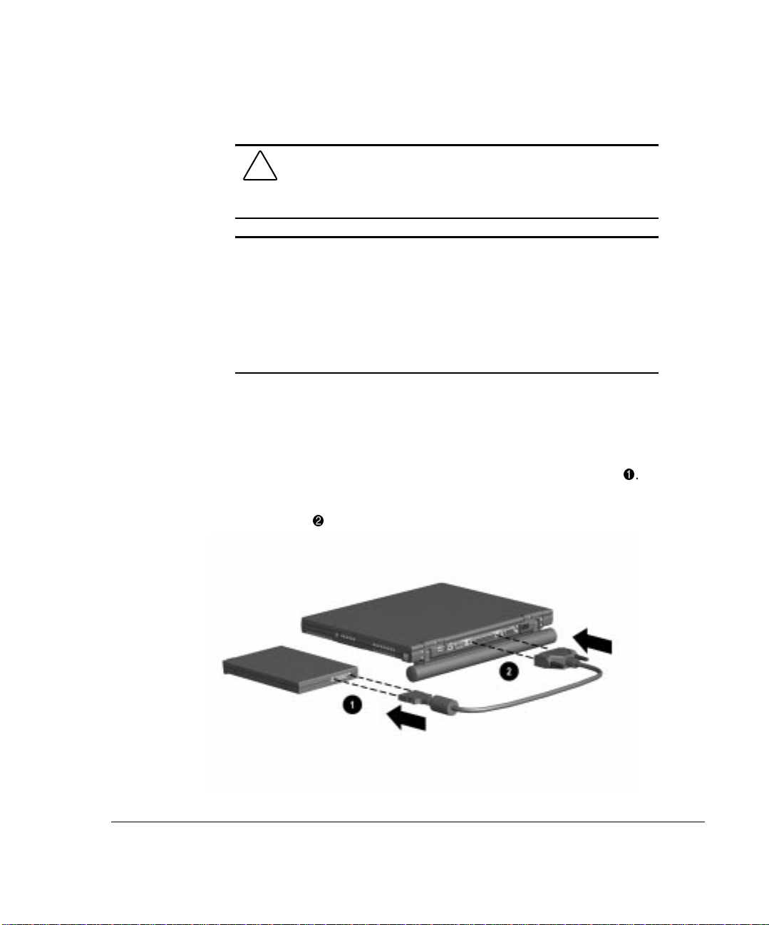
To connect the external diskette drive to the computer:
1. Attach the small end of the drive cable to the external diskette drive
2. Attach the large end of the drive cable to the parallel port on the rear of
2
the computer
.
1
.
Page 27
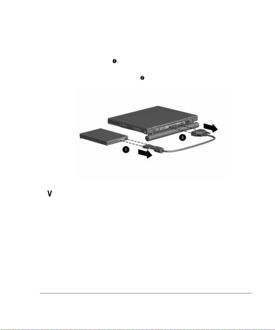
Disconnecting the Diskette Drive
To disconnect the external diskette drive from the computer:
1. Remove the diskette from the diskette drive.
2. Unscrew the small end of the drive cable from the external
diskette drive 1.
3. Unscrew the large end of the drive cable from the parallel port
on the rear of the computer
2
2-9
.
Versatile Battery Pack
The primary battery pack is a multifunctional feature of the computer. In
addition to providing portable power, it
■ Creates a comfortable tilt for working at the keyboard. Fold the battery
pack back and under the computer.
■ Provides a cover for the rear connectors. Place the battery pack in a
straight position while the computer is lying flat.
Page 28
Chapter 3
Using the Keyboard
Using the Pointing Device
The built-in TouchPad functions with any software that supports a Microsoftcompatible mouse.
NOTE: If you are using software that does not support a Microsoft-compatible
mouse, select AdvancedÅDevice Options in Computer Setup, then select the
Disable Multiple Pointing Devices check box. For more information on running
Computer Setup, please refer to Chapter 14.
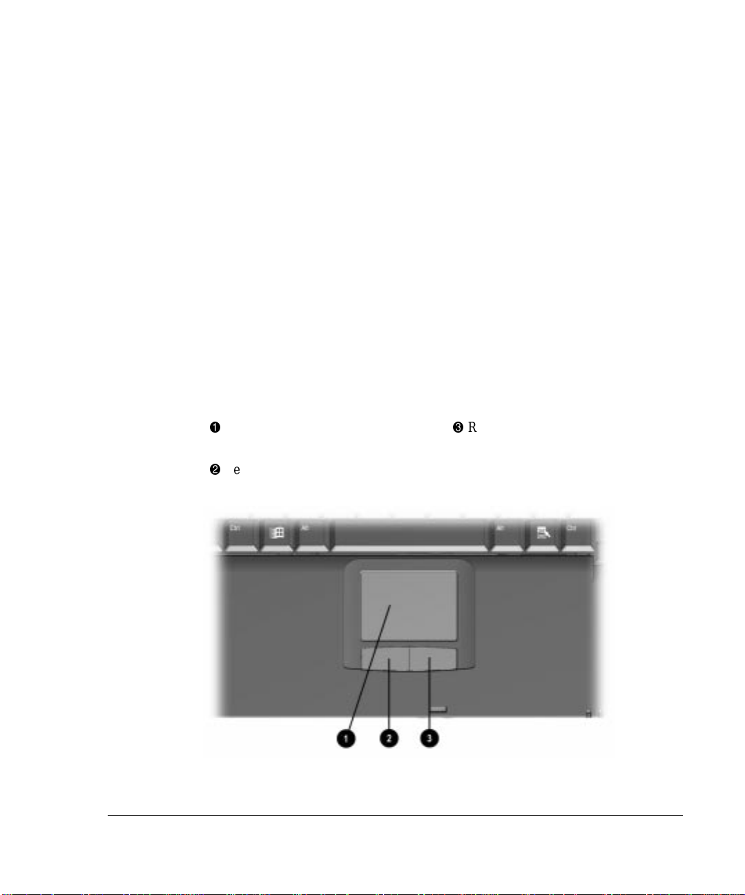
Identifying Keyboard Components
1
TouchPad
2
Left-click button
3
Right-click button
3-1
Page 29

3-2 Using the Keyboard
Navigating with the TouchPad
Move the mouse pointer Move your finger directionally across the
Increase or decrease cursor speed Increase or decrease finger speed across
Right-, left-, or double-click Press the right- or left-click button as you
Highlight an item* Press down on the TouchPad as you move
Select text or an object* Position the mouse pointer over the
Activate a selection* Position the mouse pointer over the
TouchPad Procedures
Task Procedure
TouchPad surface.
the TouchPad surface.
would the corresponding click button on
an external mouse.
the mouse pointer over the item.
highlighted text or object, then quickly tap
the TouchPad once.
selection, then quickly tap the TouchPad
twice.
NOTE: To select and activate a preference,
first tap the preference once to select it,
then tap the preference twice to activate
it.
Select, then drag and drop an item* Press down on the TouchPad as you move
the mouse pointer over the item, then drag
the item to the new location. To drop the
item, release the pressure.
*To perform this task exactly as you would with an external mouse, use the left-click button like
an external mouse left-click button.
Page 30
Setting TouchPad Preferences
To access all TouchPad features and settings including mouse trails, cursor
speed, double-click pace, and Windows 98 single-click mode, select StartÅ
SettingsÅControl PanelÅMouse.
Using Hotkeys
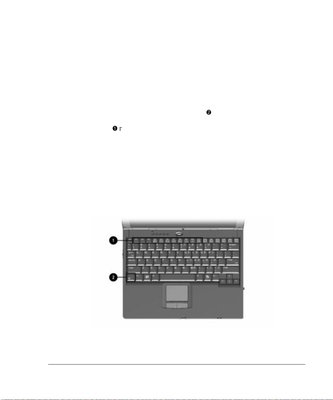
Hotkeys are preset combinations of the Fn key 2 plus a second key that
take you to frequently used system functions. The icons on the function keys
1
(F1-F10)
■ To use hotkeys on an external keyboard which does not have an Fn
■ To close a window opened with hotkeys, use standard Windows
represent these functions.
key, press the Scroll Lock key twice, then the second key only of the
hotkeys combination. For example, to use the Fn+F3 hotkeys, press
Scroll Lock+Scroll Lock+F3.
NOTE: The Fn+F6 (Initiate Quick Controls) hotkeys cannot be used on an
external keyboard connected through a USB connector.
procedures or press the hotkeys again.
3-3
Page 31

3-4 Using the Keyboard
Task Hotkeys
Switch the display and image. Fn+F4
Adjust system volume. Fn+F5
Initiate Quick Controls. Fn+F6
Set a power conservation level. Fn+F7
View battery charge status. Fn+F8
Adjust screen brightness. Fn+F10
Display system information. Fn+Esc
Stretch text. Fn+T
Switching the Display and Image
In Windows 95 or Windows NT 4.0 toggle Fn+F4 to switch the image among
the computer display, an external display, and simultaneous display. The
external display can be connected through the external monitor connector.
In Windows 98 toggle Fn+F4 to switch the image between the computer
display and an external display that is connected through the external monitor
connector.
Hotkeys Quick Reference
■ When MultiMonitor is enabled, press Fn+F4 to turn off the external
display and disable MultiMonitor.
■ When MultiMonitor is disabled, toggle Fn+F4 to switch the image
among the computer display, the external display, and simultaneous
display.
Adjusting System Volume
■ To adjust system volume with an onscreen slide button or with the
keyboard arrow keys, press Fn+F5.
■ To mute or restore volume
❏ Press Fn+F5+M
or
❏ Press Fn+F5, then select or clear the Mute checkbox.
Page 32

Initiating Quick Controls
Quick Controls security features disable the keyboard and pointing device and
clear the screen. Before you can use Quick Controls, you must set a power-on
password and enable Quick Control preferences. For instructions, refer to
Chapter 11.
■ To initiate Quick Controls manually, press Fn+F6.
■ To exit Quick Controls, enter your power-on password.
The Fn+F6 hotkeys cannot be used on an external keyboard connected through
a USB connector on the computer or an optional docking base.
Setting a Power Conservation Level
In Windows 98 press Fn+F7 to open the Power Schemes window.
In Windows 95 or Windows NT 4.0 press Fn+F7 to open the Battery
Conservation Settings window.
■ To select a preset battery conservation level, choose among
❏ High—Maximizes running time from a single charge.
❏ Medium—Balances system performance with running time.
❏ None (Drain)—Runs the computer at full power.
■ For information about the Custom level, refer to “Using Power
Preferences” in Chapter 4.
3-5
Viewing Battery Charge Status
Press Fn+F8 to view the status of all installed battery packs. Battery packs are
listed by location.
■ To display the location of a listed battery pack, select the corresponding
battery icon.
■ A lightening bolt icon beside a battery icon indicates that the battery
pack in that location is charging.
Page 33

3-6 Using the Keyboard
Adjusting Screen Brightness
Press Fn+F10 to adjust the brightness of the computer screen with an onscreen
slide button or with the arrow keys.
Displaying System Information
Press Fn+Esc to display information about system hardware components and
software version numbers.
The number beside System BIOS is the version number of your
NOTE:
system ROM.
Stretching Text
When the computer is running MS-DOS under Windows and the desktop area
resolution is set lower than the display resolution, press Fn+T to toggle the
image between Text Stretch, which stretches the text to fill more of the screen,
and Regular. Text Stretch is the default. While Regular is selected, a graphics
accelerator cannot be enabled.
Enabling the Eurocurrency Symbol
Your computer can generate the Eurocurrency symbol when pressing the
Alt Gr+4, 5, e, or u key combinations. The key combination for your computer is
dependent on the keyboard for your country and the keyboard language settings
in the operating system. On keyboards without the Alt Gr (alternate graphics)
key, use the Alt key to the right of the spacebar.
Page 34

Using the Embedded Numeric
Keypad
Toggling the Keypad On and Off
n
To convert the embedded numeric keypad section 1 of the computer
keyboard to a numeric keypad, press Fn+Num Lk
❏ When the embedded numeric keypad is enabled, the characters
upper-right on the keypad keys are active and the Num Lk light
is on.
❏ To disable the embedded numeric keypad, toggle Fn+Num Lk.
■ The embedded numeric keypad cannot be enabled while an optional
external keyboard or numeric keypad is connected to the computer.
2
3-7
.
3
Operating the Keypad Keys as Standard Keys
To use the embedded numeric keypad keys as standard keyboard keys while the
keypad is enabled:
■ Press and hold Fn to type in lowercase.
■ Press and hold Fn+Shift to type in uppercase.
Page 35

3-8 Using the Keyboard
Enabling the Keypad at Startup
To set the computer to start up with the embedded numeric keypad enabled:
1. Turn on or restart the computer, then press F10 when the blinking cursor
appears in the upper-right corner of the screen.
❏ To change the language, press F2.
❏ For navigation instructions, press F1.
2. Select AdvancedÅDevice Options, then press Enter.
3. Toggle the field beside Num Lock State at Boot to On, then press F10.
4. To save your preferences, close Computer Setup, and restart the
computer, select FileÅSave Changes and Exit, then press Enter.
5. When you are prompted to confirm your action, press F10.
To disable the embedded numeric keypad at start up, repeat the above
procedure with the Num Lock State at Boot field toggled Off.
NOTE: The embedded numeric keypad can be enabled or disabled with
Fn+Num Lk in either startup state.
Page 36

Chapter 4
Managing Power
Selecting a Power Source
WARNING: To reduce the risk of personal injury, electric shock,
fire, or damage to the equipment:
■ Do not disable the power cord grounding plug. The
grounding plug is an important safety feature.
■ Plug the equipment into a grounded (earthed) electrical outlet
that is easily accessible at all times.
■ Disconnect power from the equipment by unplugging the
power cord from the electrical outlet.
■ Do not place anything on power cords or cables. Arrange
them so that no one may accidentally step on or trip over
them.
■ Do not pull on a cord or cable. When unplugging from the
electrical outlet, grasp the cord by the plug.
4-1
Selecting a Power Source
Task Recommended Power Source
Work within installed software applications
■ Charged battery pack inserted into
the computer
or
■ External power supplied through
❏ AC Adapter
❏ Optional docking base
❏ Optional Automobile Power
Adapter/Charger or
❏ Optional Aircraft Power
Adapter
Continued
Page 37

4-2 Managing Power
Selecting a Power Source
Continued
Charge a battery pack in the computer External power supplied through
■ AC Adapter
■ Optional docking base
■ Optional Automobile Power
Adapter/Charger
Calibrate a battery pack External power supplied through
■ AC Adapter
■ Optional docking base
Modify system software External power supplied through the AC
Adapter
Page 38

Beginning, Leaving, or Resuming
Your Work
You will observe the power button 1, Suspend button 2, Fn key 3, and the
power/suspend light as you turn the computer on or off or place it in Suspend
(Standby) or Hibernation.
■ Suspend, called Standby in Windows 98, is an energy-saving feature
that reduces power to system components that are not being used. When
the computer is in Suspend (Standby), your work is saved in random
access memory (RAM) and the screen is cleared.
■ Hibernation is an energy-saving feature that saves all information in
RAM to a hibernation file on the hard drive, then shuts down the
computer.
4-3
If you are leaving your work, consider:
If you plan to resume shortly—Initiating Suspend (Standby) clears the screen,
uses less power than leaving the computer on, and your work returns instantly to
the screen when you press the suspend button. A fully charged battery pack can
support Suspend (Standby) for up to a week, but frequent charging and
discharging may shorten battery pack life.
Page 39

4-4 Managing Power
If the computer will be disconnected from external power for more than
two weeks—To extend the useful life of the battery pack, shut down the
computer, then remove the battery pack and store it in a cool, dry place.
If you plan to resume within two weeks—Initiating Hibernation clears the
screen, saves your work to the hard drive, and uses less power than Suspend
(Standby). A fully charged battery pack supports Hibernation indefinitely.
Turn the
computer on
Beginning, Leaving, or Resuming Your Work
Task Procedure Result
Press power button. Power/suspend* light turns on.
Operating system loads.
Turn the
computer off
Initiate
Suspend*
Exit Suspend*
*In Windows 98 the term
**In Windows 98 the term
Click StartÅShut Down. Power/suspend* light turns off.
■ Press suspend button.**
■ Select Standby (Windows 98
only) on the Shut Down
menu.
■ Press suspend button.**
■ Press power button.
or
or
Standby
sleep button
replaces the term
replaces the term
Operating system closes and
turns off all power.
Computer turns off.
Power/suspend* light blinks.
System beeps twice.
Screen clears.
Power/suspend* light turns on.
System beeps once.
Your work returns to the screen.
Suspend.
suspend button.
Continued
Page 40

4-5
Beginning, Leaving, or Resuming Your Work
Initiate
Hibernation
Restore from
Hibernation
*In Windows 98 the term
**In Windows 98 the term
Press Fn + suspend button.** Power/suspend* light turns off.
Press power button. Power/suspend* light turns on.
Standby
replaces the term
sleep button
replaces the term
Managing Low-Battery Conditions
Identifying Low-Battery Conditions
■ When a battery pack that is the only source of power available to the
computer reaches a low-battery condition
❏ The system beeps 5 times.
Continued
Suspend.
System beeps twice.
Screen clears.
System beeps once.
Your work returns to the screen.
suspend button.
❏ The battery light
■ If the low-battery condition is not resolved, the computer will enter a
1
blinks.
critical low-battery condition. In a critical low-battery condition,
❏ If Hibernation is enabled and the computer is on or in Suspend
(Standby)
The computer beeps twice, then initiates Hibernation.
Hibernation is enabled by default.
❏ If Hibernation is disabled and the computer is on or in Suspend
(Standby)
2
blinks. The computer remains briefly in Suspend (Standby), then
The computer beeps twice, and the power/suspend light
shuts down and your unsaved work is lost.
Page 41

4-6 Managing Power
Resolving Low-Battery Conditions
■ If external power is available, do one of the following
❏ Connect the computer to an electrical outlet with the AC Adapter.
❏ Dock the computer and mobile expansion unit in a docking base that
is connected to external power.
❏ Plug an optional Automobile Power Adapter/Charger into the power
connector on the computer and into a vehicle cigarette lighter
receptacle.
❏ Plug an optional Aircraft Power Adapter into the power connector
on the computer and into the in-seat power supply available on some
commercial aircraft.
NOTE: An optional Aircraft Power Adapter can be used to run the computer
but cannot be used to charge a battery pack.
■ If a charged battery pack is available Save your work, shut down the
computer, then remove the discharged battery pack and insert a charged
battery pack.
Page 42

■ If neither external power nor a charged battery pack is available—
❏ Press Fn + suspend button to initiate Hibernation
or
❏ Save your work, then shut down the computer.
Restoring from Hibernation After Resolving
a Critical Low-Battery Condition
Press the power button. If the computer does not have enough power to restore
your work,
1. Press Ctrl+Alt+Del to abort the restoration.
2. Attach a charged battery pack or connect the computer to external
power.
3. Press the power button.
Charging a Battery Pack
4-7
When a battery pack is installed in the computer or an optional Battery Charger
or docking base, the battery pack is charged whenever external power is
available.
NOTE: Charging may be delayed if a battery pack is new, has not been used
for 2 weeks or more, or is much warmer or cooler than a comfortable room
temperature.
■ If you are charging the battery pack in the computer—
❏ External power can be supplied to the computer from an external
power source.
NOTE: An optional Aircraft Power Adapter cannot be used to charge a battery
pack.
Page 43

4-8 Managing Power
■ To increase the accuracy of all battery charge displays—
❏ The battery light, shown below, turns on while the battery pack is
charging and turns off when the battery pack is fully charged.
❏ Allow a battery pack to discharge to the low-battery level through
normal use before charging it.
❏ When you charge a battery pack, charge it fully.
❏ Before charging a new battery pack or a battery pack that has not
been used for 2 weeks or more, calibrate the new battery pack or
check the calibration on the unused battery pack.
Monitoring the Charge in a
Battery Pack
NOTE: The references in Windows 98 battery charge displays to a “standard
APM battery pack” apply to all battery packs that can be used in the computer.
Page 44

Using the Battery Charge Level Lights
The battery quick check feature enables you to monitor the charge in the
primary battery pack.
■ To display the percent of a full charge remaining in a battery pack, press
the button on the battery pack.
■ Each battery charge level light represents a percentage of a full charge.
For example, when all lights are on, the battery pack is fully charged.
Using the Battery Status Tab
To access the Battery Status tab, select StartÅSettingsÅControl PanelÅpower
icon (named Power, Power Management, or Compaq Power, depending on your
operating system)ÅBattery Status tab.
■ To display the location of a listed battery, select the corresponding
battery icon.
■ A lightning bolt icon beside a battery icon indicates that the battery pack
in that location is charging.
4-9
Using the Battery Meter or Power Meter Icon
The battery meter icon, called the power meter icon in Windows 98, indicates
whether the computer is running on external power or on a full, half-full, or
nearly discharged battery pack.
To display the battery meter icon in the taskbar
■ In Windows 95 select StartÅ SettingsÅControl
PanelÅPowerÅBattery Status tab, then select the Show Battery Meter
on the Taskbar check box.
■ In Windows 98 select StartÅ SettingsÅControl PanelÅPower
ManagementÅPower Meter tab, then select the Show Power Meter on
the Taskbar check box.
■ In Windows NT 4.0 the battery meter icon displays in the taskbar by
default. In addition, you can select StartÅSettingsÅControl
PanelÅCompaq PowerÅBattery Status tab.
Page 45

4-10 Managing Power
When the battery meter or power meter icon is displayed in the taskbar, the icon
can also be used as follows.
In Windows 95 and Windows 98—
View the total battery power remaining in the
system.
Task Procedure
Rest the cursor over the icon.
Enable/disable an on-screen critical lowbattery warning.
Access the Power tab in the Power Properties
window.
Open battery meter in a popup window. Double-click the icon.
Display charge information as a percent of a
full charge or as the run time remaining.
In Windows NT 4.0—
Task Procedure
View the total battery power remaining in the
system.
Open the Compaq Power Properties window. Double-click or right-click the icon.
Using the Power or Power Meter Tab
Left-click the icon, select or clear the
Enable Low Battery Warning check box,
then select OK.
Right-click the icon, select Adjust Power
Properties, then press Enter.
Left-click the icon, then select your
preference in the popup window.
Rest the cursor over the icon.
The power tab, called the power meter tab in Windows 98, is available in
Windows 95 and Windows 98.
■ To access the tab
❏ In Windows 95 select StartÅSettingsÅControl PanelÅ
PowerÅPower tab.
Page 46

❏ In Windows 98 select StartÅSettingsÅControl PanelÅ Power
ManagementÅPower Meter tab.
■ To view the combined percent of total power remaining in all battery
packs in the system, clear the Show the Status of All Batteries check
box.
■ To view the percent of total power remaining in each battery pack in the
system, select the Show the Status of All Batteries check box.
Calibrating a Battery Pack
Calibration increases the accuracy of all battery charge displays.
The calibration utility supports all battery packs that can be used in the
computer.
Use the calibration utility both to check the calibration of a battery pack and to
calibrate or recalibrate a battery pack.
■ A battery pack cannot be calibrated unless the utility reports that it needs
calibration.
❏ A new battery pack can be charged, then used to run the computer
before the battery pack is calibrated. However, the amount of charge
in the new battery pack cannot be reported accurately until the new
battery pack has been calibrated.
4-11
❏ Check the calibration of a used battery pack periodically and
whenever battery charge displays seem inaccurate.
■ While a battery pack is being calibrated, it is fully charged, then fully
discharged.
❏ A battery calibration icon in the taskbar displays an Up arrow during
the charge phase and a Down arrow during the discharge phase.
❏ A calibration cannot resume if the calibration is stopped or if the
computer is shut down during a calibration. An interrupted
calibration must be restarted.
❏ After calibration, a battery pack must be charged before it can be
used to run the computer.
Page 47

4-12 Managing Power
■ The calibration utility calibrates one battery pack at a time and can run in
Running a Calibration
1. To check the calibration of a battery pack—Attach the battery pack to
2. Access the Battery Calibration tab.
the background as you use the computer or overnight.
CAUTION: To prevent loss of work, ensure that the computer
remains connected to AC power throughout a calibration.
the computer or insert a battery pack into the MultiBay of the mobile
expansion unit. If you insert the battery pack into the expasnion unit’s
MultiBay, connect the computer and expansion unit system to external
power.
To calibrate a battery pack—Attach the battery pack to the computer.
Then connect the computer to external power with the AC Adapter or
dock the computer and mobile expansion unit in a docking base that is
connected to external power
■ In Windows 95 select StartÅSettingsÅControl
PanelÅPowerÅBattery Calibration tab.
■ In Windows 98 select StartÅSettingsÅControl PanelÅPower
ManagementÅBattery Calibration tab.
■ In Windows NT 4.0 select StartÅSettingsÅControl
PanelÅCompaq PowerÅBattery Calibration tab.
Page 48

3. View the calibration reports in the Status column. The battery numbers
in the Battery column correspond to the following locations:
Battery Number Battery Pack Location
1 Computer battery bay
2 Mobile expansion unit MultiBay
4. Select any location number with “Needs calibration” beside it in the
Status column.
5. Select the Start Calibration button.
Stopping a Calibration
Shut down the computer or select the Stop Calibration button on the Battery
Calibration tab. The Stop Calibration button is visible only during a calibration.
Changing the Primary Battery Pack
4-13
The primary battery pack is the battery pack attached to the computer.
NOTE: For information on using a battery pack in the mobile expansion unit
MultiBay, refer to Chapter 6.
CAUTION: If the computer is on, you must initiate Hibernation or
shut down power before removing or installing the battery pack.
Failure to do so will result in loss of information.
WARNING: To reduce the risk of personal injury or damage to
the battery pack, do not crush, puncture, or incinerate the battery
pack or short the metal contacts. Do not attempt to open or
service the battery pack.
Page 49

4-14 Managing Power
Removing the Primary Battery Pack
1. If the computer is on, save your work and initiate Hibernation or shut
down the computer.
2. Turn the computer bottom side up and tilt the battery pack so it lies flat
(covering all ports on the rear of the computer).
3. Slide in the two battery latches toward each other.
Page 50

4. Rotate the battery pack 90 degrees 1, and lift up the battery pack from
2
the computer
.
Installing the Primary Battery Pack
1. If the computer is on, save your work and initiate Hibernation or shut
down the computer.
4-15
2. Turn the computer bottom side up.
Page 51

4-16 Managing Power
3. Slide in the two battery latches toward each other.
Page 52

4. Push the battery pack onto the computer until the contacts connect 1, and
2
rotate the battery pack 90 degrees toward the back of the computer
.
4-17
5. Slide the two battery latches out (away from each other)
3
.
Storing the Battery Pack
If the computer will be unused and unplugged from an external power source
for more than two weeks, remove and store the battery pack(s).
Proper storage procedures reduce the self-discharge rate of a battery pack. Store
a battery pack in a cool, dry place within the following temperature ranges.
CAUTION: To prevent damage to a battery pack, do not expose
it to high temperatures for extended periods of time.
Page 53

4-18 Managing Power
Recommended Battery Pack Storage Temperatures
Storage Time Temperature Range
Less than 1 month 32°–122° 0°–50°
No more than 3 months 32°–104° 0°–40°
Unlimited 32°– 86° 0°–30°
Using Power Preferences
You can increase, decrease, and allocate the power used by the computer by
setting power preferences.
■ Increasing power increases performance, while decreasing power
conserves energy and extends the running time from a battery pack.
■ By decreasing power to unused components and functions, you can
allocate more power to the components and functions that you are using.
Many power preferences are timeout settings.
■ A timeout is the period of inactivity before the system initiates a power
change or reduces power to a component. For example, the computer is
preset to initiate Suspend (Standby) after a period of inactivity. The time
interval between when you stop using the computer and the onset of
computer-initiated Suspend (Standby) is a Suspend (Standby) timeout.
Temperature Range
°F
°C
■ Depending on your operating system, you can set timeouts that are
specific to various conditions, components, or procedures as well as
specify the duration of those timeouts.
For additional power options, refer to your operating system documentation. For
a summary of battery conservation settings that extend the running time from a
single charge, refer to “Conserving Battery Power” later in this chapter.
The following tables list power procedures that are not described in your
operating system documentation.
Page 54

Setting Power Preferences in Windows 95 or
Windows NT 4.0
Setting Power Preferences in Windows 95 or Windows NT 4.0
Preferences Procedure from Control Panel
Select a preset level of power use that
applies whenever the computer is running on
a battery pack.
NOTE: A battery conservation level can also
be displayed and selected with the Fn+F7
hotkeys.
4-19
Select Power (or Compaq Power in
Windows NT)ÅBattery Conservation
Settings tab, then select a conservation
level:
■ High provides maximum battery
conservation.
■ Medium balances battery
conservation and system
performance.
■ None (drain) results in maximum
battery drain because battery
conservation is turned off.
Recommended only for
discharging the battery pack.
Create a level of power use that applies
settings for the following whenever the
computer is running on a battery pack:
■ Suspend timeout
■ System idle timeout
■ Processor speed
■ Screen brightness
Select Power (or Compaq Power in
Windows NT)ÅBattery Conservation
Settings tab. Select Custom, then enter
your preferences.
NOTE: Although a battery conservation
level can be displayed and selected with
the Fn+F7 hotkeys, Custom level
preferences must be entered on the
Battery Conservation Settings tab.
Continued
Page 55

4-20 Managing Power
Setting Power Preferences in Windows 95 or Windows NT 4.0
In Windows NT, create a general level of
power use that applies whenever the
computer is running on external AC power.
You can enter settings for
■ Screen save timeout
■ Hard drive timeout
■ Energy-saving monitor timeout
1. Select Compaq PowerÅAC Energy
Saver tab.
2. Select the AC Energy Saver On
button.
3. To set a screen save timeout,
select a timeout in the Screen
Save drop-down list.
4. To set a hard drive timeout, select
a timeout in the Hard Disk Idle
Continued
drop-down list.
5. To enable an external monitor to
enter a low-power mode following
a screen save timeout, select the
Energy Save Monitor check box.
NOTE: You will not be logged off a
network when the monitor enters lowpower mode.
Enable/disable low-battery warning beeps. Select Power (or Compaq Power in
Windows NT)ÅBattery Conservation
Settings tab, then select the On or Off
button.
Set Hibernation timeout. Select Power (or Compaq Power in
Windows NT)ÅHibernation tab, then
select a timeout from the Timeout
drop-down list.
NOTE: This setting does not affect
system-initiated Hibernation during a
critical low-battery condition.
Exit Suspend after a user-selected timeout. Select Power (or Compaq Power in
Windows NT)ÅResume Timer tab. Select
the Enabled check box, then select a date
from the Date drop-down list and a time
from the Time drop-down list.
Continued
Page 56

4-21
Setting Power Preferences in Windows 95 or Windows NT 4.0
Set computer to initiate Hibernation rather
than Suspend.
In Windows 95, turn off power to an optional
PC Card modem.
Change location of Hibernation file. Select Power (or Compaq Power in
Enable/Disable Hibernation. Select Power (or Compaq Power in
Select Power (or Compaq Power in
Windows NT)ÅHibernation tab, then
select Standby in the Timeout drop-down
list.
Select PowerÅPC Card Modems tab,
then select Turn Off Power to PC Card
Modem When Not in Use check box.
Windows NT)ÅHibernation tab, then
select the new location from the Drive for
Hibernation File drop-down list.
Windows NT)ÅHibernation tab, then
select the On or Off button.
CAUTION: If the computer reaches a
critical low-battery condition while
Hibernation is turned off, unsaved work
can be lost.
Continued
Setting Power Preferences in Windows 98
To access most power settings—Select StartÅ SettingsÅControl
PanelÅPower Management. For information about setting all Power
Management settings except the following, refer to your Windows98
documentation.
To enable or disable hibernation—Select the hibernation tab, then select the
on or off button.
To set a screen brightness level that applies when the computer is running
on a battery pack—Select Power ManagementÅBattery Conservation Settings
tab, then select a percent from the Brightness drop-down list.
Page 57

4-22 Managing Power
If you are accustomed to running Windows 95 or Windows NT 4.0 on a
Compaq portable computer—You will find most of the power options you
formerly accessed in Power Properities in the Windows 98 Power Management
Properties window. However, in windows 98
■ Processor speed is managed by the operating system.
■ The easiest way to turn off power to a PC Card is to remove the
PC Card.
■ The Fn+F7 hotkeys open the Power Schemes window.
■ The preferences you formerly set on the Resume Timer tab can be set at
StartÅProgramsÅAccessoriesÅSystem ToolsÅScheduled Tasks.
Turning Auto Insert Notification On or Off
When using the computer with the mobile expansion unit, auto insert
notification runs a CD-ROM or DVD-ROM on insertion in the expansion unit
MultiBay, but drains power and prevents system-initiated Suspend (Standby).
To turn off auto insert notification:
■ In Windows 95 or Windows 98 select StartÅSettingsÅ Control
PanelÅSystemÅDevice ManagerÅCD-ROMÅ Properties. Clear the
CD-ROM Auto Insert Notification check box.
■ In Windows NT 4.0 select StartÅSettingsÅControl PanelÅCompaq
PowerÅBattery Conservation Settings tab. Clear the CD-ROM Auto
Insert Notification check box.
To turn on auto insert notification, access the CD-ROM Auto Insert Notification
check box as instructed above, then select the check box.
Conserving Battery Power
Battery Power Conservation Checklist
■ Exit modem applications and turn off local area network (LAN)
connections when you are not using them.
■ Disconnect external equipment you are not using that is not connected to
an external power source.
Page 58

■ If you leave your work, initiate Suspend (Standby) or Hibernation or
shut down the computer.
■ Remove PC Cards you are not using.
■ Use the Fn+F10 hotkeys to quickly raise and lower display brightness as
you work.
■ Run the computer on external power while formatting a diskette.
■ When using the computer with the mobile expansion unit and a CD-
ROM or DVD-ROM drive is in the system, select
StartÅSettingsÅControl PanelÅSystemÅDevice ManagerÅCD-ROM
properties, then clear the CD-ROM Auto Insert Notification check box.
Conserving Battery Power in Windows 95
■ Select StartÅSettingsÅControl PanelÅPower. Then:
❏ On the Battery Conservation Settings tab, select the High or Custom
battery conservation level. If Custom is selected, enter lower
settings.
❏ On the Disk Drives tab, set a low When Powered by Batteries
timeout for the disk drive.
4-23
❏ If you are using a PC Card modem, select the PC Card Modems tab,
then click the Turn Off PC Card Modems When Not in Use check
box.
■ If Infrared Monitor is enabled, select StartÅSettingsÅControl
PanelÅInfraredÅOptions tab, then clear the Search for and Provide
Status for Devices in range check box.
IMPORTANT: You cannot establish an infrared link while this check box is
cleared. For more information about infrared, refer to Chapter 10.
Conserving Battery Power in Windows 98
■ Select StartÅSettingsÅControl PanelÅPower ManagementÅPower
Schemes tab, then create a power scheme that conserves battery power.
■ Select StartÅSettingsÅControl PanelÅPower ManagementÅBattery
Conservation Settings. Then select a low screen brightness.
Page 59

4-24 Managing Power
■ Choose the Infrared icon in the task bar, select the Options tab, then
clear the Search for and Provide Status for Devices in Range check box.
IMPORTANT: You cannot establish an infrared link while this check box is
cleared. For more information about infrared, refer to Chapter 10.
Conserving Battery Power in Windows NT 4.0
Select the Start buttonÅSettingsÅControl PanelÅCompaq PowerÅBattery
Conservation Settings tab, then select the High or Custom conservation level. If
Custom is selected, enter lower settings.
Page 60

Chapter 5
Upgrading Your Computer
Memory
Managing Random Access Memory (RAM)
To view the amount of existing random access memory (RAM) in the system
■ In Windows 95 or Windows 98 select StartÅ SettingsÅControl
PanelÅCompaq Diagnostics.
■ In Windows NT 4.0 select StartÅProgramsÅ Administrative
ToolsÅCompaq Diagnostics.
You can increase RAM with optional memory expansion boards. For ordering
information, go to the Compaq Internet site at http://www.compaq.com or refer
to Appendix A to contact a Compaq authorized dealer, reseller, or
service provider.
When RAM increases, the hard drive space reserved for the hibernation file also
increases. Windows 98 manages this increase. If the computer is running
Windows 95 or Windows NT 4.0 and you experience problems with
Hibernation after increasing RAM, verify that your hard drive has enough free
space for the larger hibernation file.
5-1
■ To view the amount of space required by a hibernation file
❏ In Windows 95 or Windows 98 select StartÅSettingsÅControl
PanelÅPowerÅHibernation tab.
❏ In Windows NT 4.0 select StartÅSettingsÅControl
PanelÅCompaq PowerÅHibernation tab.
■ To view the amount of free space on your hard drive, select My
ComputerÅright-click your hard driveÅProperties.
Page 61

5-2 Upgrading Your Computer
Removing or Inserting a
Memory Expansion Board
NOTE: There is only one memory expansion slot in the computer. Before
upgrading memory, you must remove the memory board that came with the
computer.
WARNING: The memory compartment and the real time clock
battery compartment are the only user-accessible internal
compartments on the computer. All other areas that require a tool
to access should be opened only by a Compaq authorized service
provider.
WARNING: Failure to unplug the power cord and remove
the battery pack before installing a memory expansion board
can damage the equipment and expose you to the risk of
electrical shock.
CAUTION: Electrostatic discharge (ESD) can damage electronic
components. Before beginning this procedure, ensure that you are
properly grounded. For more information, refer to Appendix C,
“Electrostatic Discharge.”
1. Shut down the computer.
NOTE: To ensure that the computer is not in hibernation, turn the computer
on, then shut it down.
2. Disconnect all external devices connected to the computer.
3. Disconnect the AC Adapter and remove the battery pack from the
computer.
Page 62

4. Gently press down on each of the three tabs along the top edge of the
1
keyboard
45-degree angle from the computer
5. If applicable, turn back the memory insulator.
, then lift along the top edge to raise the keyboard at a
2
.
5-3
Page 63

5-4 Upgrading Your Computer
6. To remove the memory board, pull away the plastic retention clips on
each side of the memory expansion board
board tilts upward.
7. Lift the edge of the memory expansion board and slide it gently out of the
memory expansion slot at a 45-degree angle
1
. The memory expansion
2
.
8. Place the removed memory expansion board in an electrostatic-safe
container.
Page 64

9. To add a memory board, insert the memory expansion board into the
1
empty memory expansion slot at a 45-degree angle
gently into place until it is seated while tilted.
NOTE: All memory expansion boards supported by the computer are keyed
(notched) to ensure correct positioning.
. Then slide it
5-5
10. Push the memory expansion board down until the plastic retention clips
snap into place.
11. Replace the memory insulator, if applicable.
12. Replace the keyboard by gently pressing down on the top of the keyboard
until it clicks into place.
2
Page 65

5-6 Upgrading Your Computer
Hard Drives
CAUTION: To prevent damage to the computer and drive and
loss of information, turn off the computer before removing or
inserting the hard drive. Do not remove or insert the drive while
the computer is turned on, in Suspend (Standby), or in
Hibernation.
Electrostatic discharge can damage electronic components.
Before touching the hard drive, ensure that you are discharged of
static electricity by touching a grounded metal object.
NOTE: The primary hard drive cannot be used in the mobile expansion unit
MultiBay. For information on using hard drives in the mobile expansion unit
MultiBay, refer to Chapter 6.
Removing the Primary Hard Drive
1. If the computer is on, save your work and shut down the computer.
NOTE: To ensure that the computer is not in hibernation, turn the computer
on, then shut it down.
2. Turn the computer bottom side up, and remove the hard drive screw
1
.
Page 66

3. Pull up on the drive’s front bezel 2, and slide the hard drive from the bay
3
.
Inserting the Primary Hard Drive
1. If the computer is on, save your work and shut down the computer.
5-7
NOTE: If you are unsure whether the computer is off or in Hibernation, turn
the computer on by pressing the power button, then shut it down.
2. Turn the computer bottom side up.
Page 67

5-8 Upgrading Your Computer
3. Slide the hard drive into the bay until the connector is seated 1, then push
the drive’s front bezel down to secure the drive
4. Insert the hard drive screw into the computer 3.
2
.
Page 68

Caring for Drives
5-9
CAUTION: To prevent loss of work and/or damage to the
computer or a drive:
■ Shut down the computer before removing or inserting a hard
drive. Do not remove or insert a hard drive while the
computer is on, in Suspend (Standby), or in Hibernation. If you
are not certain whether the computer is off or in Hibernation,
turn the computer on, then shut it down.
■ Before handling a drive, ensure that you are discharged of
static electricity. While handling a drive, avoid touching the
connector. For more information about preventing
electrostatic damage, refer to Appendix C.
■ Before traveling with, shipping, storing, or removing a drive
other than a hard drive, make sure that no media, such as a
diskette or CD-ROM, is in the drive and that the media tray is
closed.
■ Handle a drive carefully; do not drop it.
■ Do not use excessive force when inserting a drive.
■ Avoid exposing a hard drive to liquids, temperature extremes,
or products that have magnetic fields such as monitors or
speakers.
■ If a drive must be mailed, place the drive in a bubble-pack
mailer or other suitable protective packaging and label the
package “Fragile: Handle With Care.”
Changing the Startup Sequence with
MultiBoot
When the computer is attached to the mobile expansion unit and more than one
drive is in the system, the computer selects the drive to start from by searching
for, first, a bootable CD-ROM or DVD-ROM; second, a bootable diskette; and
third, a bootable hard drive.
NOTE: A bootable device contains files needed by the computer to start up and
operate properly.
Page 69

5-10 Upgrading Your Computer
The computer can start from
■ Any bootable hard drive in the computer or diskette in the external
diskette drive.
■ Any bootable diskette (but not a SuperDisk LS-120 drive diskette) or
hard drive in a docking base.
■ Any bootable CD-ROM or DVD-ROM in a docking base.
By default, Phoenix MultiBoot is disabled and the computer selects the startup
drive by searching these locations in this sequence:
1. External diskette drive
2. Computer hard drive bay 4. Mobile expansion unit MultiBay
3. Mobile expansion unit diskette drive
bay
To enable MultiBoot and change the sequence of the computer drive bay
locations that the computer searches during startup:
1. Restart the computer, then press F10 when the blinking cursor appears
upper-right on the screen.
■ To change the language, press F2.
■ For navigation instructions, press F1.
2. Select AdvancedÅBoot Options, then press Enter.
3. Toggle the MultiBoot field to Enable.
4. Toggle the Boot Order fields to the boot sequence you prefer.
5. To save your preferences and exit Boot Options, press F10.
6. To confirm saving your changes close Computer Setup, and restart the
computer, select FileÅSave Changes and Exit, then press F10.
When the computer restarts and searches for a startup drive, it considers only
the first drive of each type. For example, in the default boot order, the computer
will not start from a bootable diskette in the diskette drive bay of the mobile
expansion unit if a non-bootable diskette is in the external diskette drive
connected to the computer.
Page 70

IMPORTANT: Changing the boot order also changes the logical drive
designations. For example, if you start up from a hard drive in the mobile
expnasion base MultiBay, it becomes drive C and a hard drive in the primary
hard drive bay becomes drive D. Starting up from a network card does not
affect logical drive designations.
Docking Devices
The mobile expansion unit is available on select models and can be purchased
as an upgrade for other models.
In addition to the mobile expansion unit, the computer can also be used with
other compatible Compaq docking devices. The computer must be docked in the
mobile expansion unit before docking the entire system to a docking device. For
more information on the individual docking solutions, contact your local
authorized Compaq reseller or provider.
5-11
Page 71

Chapter 6
Mobile Expansion Unit (available on select models)
Connecting the Computer
To connect the computer to the mobile expansion unit:
1. Close computer display
2. Align the tabs in front of the computer with the computer tabs on the
mobile expansion unit ➊. Lower the computer onto the expansion
connector ➋ and snap into place.
NOTE: Firmly press down on the rear of the computer to ensure the
computer and the mobile expansion unit are connected.
6-1
Page 72

6-2 Mobile Expansion Unit (on select models)
3. Slide the display latch ➊ to open the computer ➋.
Disconnecting the Computer
To disconnect the computer from the mobile expansion unit, follow these steps:
1. Close the computer display.
Page 73

2. On the mobile expansion unit, press the docking release button ➊ to
release the expansion unit from the computer ➋.
3. Lift the rear end of the computer to disconnect it from the computer
expansion connector
2
.
6-3
4. Pull the computer away from the mobile expansion unit tabs
Docking and Undocking to a
Compatible Docking Device
Your computer must be attached to the mobile expansion unit before the system
can be docked to another docking device. Docking the system to the docking
device provides a permanent desktop workstation. Consult the docking device
installation and operations guide or your Compaq authorized dealer for more
information about docking and undocking.
3
.
Page 74

6-4 Mobile Expansion Unit (on select models)
Turning Equipment On and Off
When the computer and mobile expansion unit are connected, turn the
equipment on and off using the power button on the computer.
If the computer and the mobile expansion unit are docked to a docking device,
follow the instructions in the docking device guide for turning equipment on and
off.
Connecting the AC Adapter
WARNING: To reduce the risk of personal injury, electric
shock, fire, or damage to your equipment:
■ Do not disable the power cord grounding plug. The grounding
plug is an important safety feature.
■ Plug the equipment into a grounded (earthed) electrical outlet
that is easily accessible at all times.
■ Disconnect power from the equipment by unplugging the
power cord from the electrical outlet.
■ Do not place anything on power cords or cables. Arrange
them so that no one can accidentally step on or trip over
them. Do not pull on a cord or cable. When unplugging from
the electrical outlet, grasp the cord by the plug.
WARNING: To reduce the risk of electric shock, fire, or damage
to the equipment, do not attempt to power the computer with a
voltage converter kit sold for appliances.
Page 75

To connect the AC Adapter, do the following:
1. Connect the AC adapter to the power connector on the left side of the
mobile expansion unit ➊.
6-5
2. Connect the AC power cord to the adapter
3. Plug the power cord into an electrical outlet
Connecting External Devices
To connect devices to the mobile expansion unit:
2
3
.
.
1. Turn off power to the computer, expansion unit, and all devices.
2. Connect external devices to the rear connectors on the expansion unit
and turn on power to all devices.
NOTE: To complete the device connections, some manufacturers require you
to install a software driver. Refer to the documentation included with the
device for details.
Page 76

6-6 Mobile Expansion Unit (on select models)
Operating External Devices
To ensure that devices connected to the expansion base are activated, follow the
guidelines below.
■ When adding a device to or removing a device from the expansion unit,
turn off power to the computer, expansion unit, and applicable devices
before connecting or disconnecting the computer.
■ When the computer is connected to the mobile expansion unit, be sure all
attached devices are turned on, then turn on power to the computer.
Drive Devices
The mobile expansion unit supports a second hard drive, CD-ROM drive,
DVD-ROM drive, LS-120 drive, or extra battery pack in the MultiBay on the
front right side of the unit. In addition, it supports a diskette drive in the
Diskette Drive Bay on the front left side of the unit.
CAUTION: Electrostatic discharge can damage electronic
components. Before touching a MultiBay device or diskette drive,
ensure that you are discharged of static electricity by touching a
grounded metal object.
IMPORTANT: If you are using Windows 95, Windows 98, or Windows
NT 4.0 preinstalled by Compaq, you do not need to turn off the computer
before removing a diskette drive, CD-ROM drive, DVD-ROM drive, LS-120
drive, hard drive, or battery pack from the mobile expansion unit. If you
installed Windows 95, Windows 98, or Windows NT 4.0 that you purchased
separately, you must obtain additional software from Compaq to support
removing these drives while the computer is on or in Suspend (Standby). For
more information about the software, refer to the Compaq Internet site at
http://www.compaq.com.
Page 77

Drives Support
Bay Device Bay Location Insert/Remove Drive
Hard Drive Computer hard drive bay
Drives Support
or
Mobile expansion unit
MultiBay
6-7
While Computer Is
Off
On, Suspend, or Off
Diskette Drive External diskette drive
CD-ROM Drive Mobile expansion unit
DVD-ROM Drive Mobile expansion unit
SuperDisk LS-120 Drive Mobile expansion unit
Extra Battery Pack Mobile expansion unit
Removing a MultiBay Device
To remove a device from the MultiBay in the mobile expansion unit:
1. If the MultiBay device is a drive, remove any DVD, CD, or diskette disc
from it.
On, Suspend, or Off
or
Mobile expansion unit
diskette drive bay
On, Suspend, or Off
MultiBay
On, Suspend, or Off
MultiBay
On, Suspend, or Off
MultiBay
On, Suspend, or Off
MultiBay
Page 78

6-8 Mobile Expansion Unit (on select models)
2. Slide forward the MultiBay release latch 1 on the right side of the
mobile expansion unit.
3. Pull the MultiBay device from the MultiBay
Inserting a MultiBay Device
2
.
To insert a device into the MultiBay in the mobile expansion unit, be sure the
drive connector is facing in, then slide the MultiBay device into the MultiBay
until the connector is seated.
Page 79

Removing the Diskette Drive from the
Diskette Drive Bay
To remove the diskette drive from the Diskette Drive Bay in the mobile
expansion unit:
6-9
1. Remove the diskette from the diskette drive.
2. Slide forward the diskette drive release latch 1.
2
3. Slide the diskette drive from the bay
.
Page 80

6-10 Mobile Expansion Unit (on select models)
Page 81

Inserting the Diskette Drive into the Diskette
Drive Bay
To insert the diskette drive into the Diskette Drive Bay in the mobile expansion
unit:
1. Remove the drive connector cord from the external diskette drive that
came with the computer.
2. With the drive connector facing in, slide the diskette drive into the
Diskette Drive Bay until the connector is seated.
6-11
Page 82

Chapter 7
Using an Internal Modem
(available on select models)
Connecting the Modem Cable
The Compaq internal modem must be connected to a standard (analog)
telephone line.
IMPORTANT: Immediately disconnect an accidental connection to a digital
line, such as an office PBX line.
1. Plug either end of the modem cable included with the computer into the
RJ-11 jack on the computer
2. If you are connecting the cable to a telephone jack that is not an RJ-11
jack, plug the country-specific modem adapter, included with the
computer, into the telephone jack.
3. Plug the other end of the modem cable into the country-specific modem
adapter or into the RJ-11 telephone jack
1
7-1
.
2
.
Page 83

7-2 Using an Internal Modem (available on select models)
Selecting Communications Software
You can operate the modem with preinstalled or optional software. To use
preinstalled modem software, select StartÅPrograms. Then,
■ In Windows 95 select AccessoriesÅFaxÅCompose New Fax.
■ In Windows 98 or Windows NT 4.0 select RingCentral Fax.
Configuring the Modem
The settings you may be required to enter vary among communications software
applications. As you enter these settings, the following information may be
helpful.
Recommended Settings
■ Model—
❏ Select StartÅSettingsÅControl PanelÅModem
or
❏ Enter the initialization string AT&F1&D2&C1E0V1S0=0.
NOTE: Newer initialization strings may be available from the Compaq
Internet site at http://www.compaq.com.
■ COM port settings—Refer to Appendix D.
■ Fax class—Select 1.
■ Parity—Select NONE.
■ Word length—Select 8.
■ Stop bits—Select 1.
■ Hardware flow control—Select RTS/CTS.
■ Speed—Select the highest transmission speed or baud rate.
❏ The maximum connection speed is determined by the speed of the
slowest modem on the connection. The internal modem negotiates
the fastest speed possible with the remote modem.
Page 84

❏ The internal modem supports
Standard analog modem communication protocols (for speeds
up to 33.6 Kbps).
ITU-compatible V.90 and 56K protocols (for higher speeds).
❏ The V.90 protocols allow faster downloads only from V.90
K56flex–compliant digital sources. Maximum achievable download
transmission rates are currently unknown, may not reach 56Kbps,
and will vary with line conditions.
Using Modem Commands and Dial Modifiers
You can configure most communications software without the use of AT
commands or dial modifiers.
■ If you prefer to configure the modem using AT commands, select
StartÅProgramsÅAccessoriesÅHyperTerminal.
■ To access an AT command set including dial modifiers and instructions,
go to the Compaq Internet site at
http://www.compaq.com/support/portables.
7-3
Setting Modem Preferences
The following preference is in addition to those described in your modem
communication software documentation.
In Windows 95 only—To set the computer to turn on when the modem
receives a telephone call, select StartÅSettingsÅControl
PanelÅPowerÅPower tabÅAdvanced button, then select the Wake Up the
Computer When the Phone Rings check box.
Using the Modem
The internal modem supports all operations described in most communications
software documentation.
If you are using a fax application, the following supplementary information may
be helpful.
Page 85

7-4 Using an Internal Modem (available on select models)
■ Fax speed—Fax communication software enables the modem to send
and receive faxes at 14,400 bps.
■ Installing and loading fax communication software—
❏ Install no more than one fax application. If more than one fax
application is installed, conflicts may occur because all fax
applications use similar files.
❏ When some fax applications are loaded, their fax drivers may
disrupt other modem functions. If you experience problems with the
modem after installing your fax application, the drive may need to
be unloaded from memory. Refer to the fax application
documentation for information about unloading the driver.
■ Sending a Fax—
❏ Opening the fax application loads the application fax driver and
prepares the modem to send the fax.
❏ If you prepare the fax in another application, you may need to select
your fax driver from within the Print Setup menu of that application.
■ Receiving a Fax—For the modem to receive a fax, a fax driver must be
loaded and the fax application must be open.
❏ If you have enabled auto receive within your fax application,
opening the application loads the fax driver and prepares the modem
to receive a fax.
❏ If you are using a Windows fax application, you can receive a fax
while using another application by opening, then minimizing, the
Windows fax application.
Page 86

Using the Modem
While Traveling Internationally
Using a Country-Specific Modem Adapter
Telephone jacks vary by country. The modem cable included with the computer
plugs directly into an RJ-11 telephone jack. To plug the modem cable into a
different type of telephone jack, you must use a country-specific modem cable
adapter. A cable adapter is provided with the computer. To obtain a different
country-specific adapter(s) required for your itinerary, refer to Appendix A to
contact a Compaq-authorized dealer, reseller or service provider.
To connect the modem using a country-specific modem adapter:
1. Plug either end of the modem cable included with the computer into the
1
RJ-11 jack on the computer
2. Plug the country-specific modem adapter into the telephone jack
3. Plug the modem cable into the country-specific modem adapter
.
3
2
7-5
.
.
Page 87

7-6 Using an Internal Modem (available on select models)
Selecting a Country-Specific Modem
Configuration
First, determine which type of modem is installed in your computer. To do so,
select StartÅSettingsÅControl PanelÅModem. If the label "3Com" is at the
end of the modem name, use the instructions for internal modems by 3Com
below. If that label is not there, use the instructions for all other internal
modems below.
■ 3Com internal modems—select StartÅProgramsÅCompaq internal
modemÅWorldPortÅGeneral tab, then select the country in which you
will be using the modem.
■ All other internal modems—select StartÅSettingsÅControl
PanelÅModemÅDialing Properties, then select the country where you
will be using the modem.
Travel Connection Checklist
If you experience connection problems while using the modem outside your
home country, the following suggestions may help.
■ Check the telephone line type—The modem requires an analog, not a
digital, telephone line. A telephone line described as a data line, fax
machine line, modem line, or standard telephone line is probably an
analog line.
■ Check for pulse or tone dialing—Dial a few digits on the telephone
and listen for clicks (pulses) or tones. Then make sure your
communication software is set to the corresponding dialing mode (pulse
or tone).
■ Check the telephone number you are dialing and the response of the
remote modem—Dial the telephone number on the telephone, wait for
the remote modem to answer, then hang up.
Page 88

■ Set the modem to ignore dial tones—If the modem receives a dial tone
it does not recognize, it will not dial and will display a No Dial Tone
error message. To set the modem to ignore all dial tones before dialing:
1. Select StartÅSettingsÅControl PanelÅModems.
2. Select your modem, then select PropertiesÅConnections tab, then
clear the Wait for Dial Tone Before Dialing check box.
NOTE: If you have a 3Com modem (see "Selecting a Country-Specific
Modem Configuration," above) and continue to receive the No Dial Tone error
message after clearing the checkbox, select StartÅ ProgramsÅCompaq
ModemÅWorldPort. Select USA, then again clear the Wait for Dial Tone Before
Dialing check box.
7-7
Page 89

Chapter 8
Using PC Cards
A PC Card is a credit card–sized accessory designed to conform to the standard
specifications of the Personal Computer Memory Card International Association
(PCMCIA). The computer supports both 32-bit CardBus cards and 16-bit
PC Cards.
Configuring a PC Card
CAUTION: If you install card and socket services or enablers
provided by a PC Card manufacturer, you may not be able to use
other PC Cards. If you are instructed by PC Card documentation to
install device drivers
■ Install only the device drivers for your operating system.
■ Do not install card services, socket services, or enablers.
■ In Windows 95 or Windows 98 the operating system configures plug
and play PC Cards.
■ In Windows NT 4.0 with CardWare provided by Compaq you can
configure a PC Card in the CardWare window:
8-1
❏ First, insert the PC Card as instructed later in this chapter.
❏ Then, open the CardWare window by selecting
StartÅProgramsÅCardWare.
❏ For additional instructions, refer to the Help program within
CardWare.
Inserting or Removing a PC Card
■ In Windows 95 or Windows 98—
❏ If you insert a PC Card while the computer is on, the computer
beeps twice when the card is ready for use.
❏ If you remove a PC Card while the computer is on, the computer
beeps twice when the card is removed.
Page 90

8-2 Using PC Cards
■ In Windows NT 4.0 with CardWare provided by Compaq—
Inserting a PC Card
1. With the connector facing the computer and the label facing up, push the
2. Gently push the card into the slot until the card is seated.
❏ When a PC Card is in the system, the PC Card icon displays on the
taskbar.
❏ If you insert a PC Card while the computer is on, the computer
beeps three times when the card is recognized.
❏ If you remove a PC Card while the computer is on, the computer
beeps three times when the card is removed.
❏ The PC Card icon displays in the taskbar whether or not a PC Card
is in the system.
CAUTION: To prevent damage to the connectors, use minimal
pressure as you insert a PC Card into the PC Card slot.
PC Card through the PC Card doors, aligning the card on the two
guide rails within the PC Card slot.
Page 91

3. In Windows NT 4.0 with CardWare provided by Compaq only—
Restart the computer if you are instructed to do so by the PC Card
documentation or an on-screen prompt.
■ If you are inserting a LAN, SCSI, or multifunction PC Card, you must
restart the computer.
■ If you are inserting a modem, ATA, flash, or SRAM PC Card, it is
usually not necessary to restart the computer.
Removing a PC Card
■ First, prepare the system for the removal:
❏ In Windows 95 or Windows 98—If the computer is on, stop the
PC Card before you remove it. To stop a PC Card, select the PC
Card icon in the taskbar, then select the PC Card you want to stop.
A message displays when the PC Card can be safely removed.
8-3
CAUTION: If the computer is on and running Windows 95,
failure to stop a PC Card before removing it may cause loss of
data.
❏ In Windows NT 4.0 with CardWare provided by Compaq
only—If the computer is on, you must shut it down before removing
some PC Cards. Refer to the PC Card documentation for removal
requirements.
Note: You must shut down the computer before removing a LAN, SCSI, or
multifunction PC Card. It is usually not necessary to shut down the
computer before removing a modem, ATA, flash, or SRAM card.
Page 92

8-4 Using PC Cards
■ Second, remove the PC Card:
1. Push the PC Card eject button
2. Gently grasp the card and pull it out
1
.
2
.
Page 93

Chapter 9
Using Audio Features
Using the Internal Microphone
and Stereo Speakers
9-1
■ The microphone
audio input when the display is open or closed.
1
has a standard sensitivity of -50 dB and supports
Page 94

9-2 Using Audio Features
■ The speaker
2
provides audio playback for multimedia applications.
When the computer is docked in the mobile expansion unit,
these speakers are disabled and system sound plays through the mobile
expansion unit’s bass speakers.
Page 95

Connecting an External Audio Device
CAUTION: To prevent possible damage to an external device,
do not plug a single-sound channel (monaural) connector into the
stereo speaker/headphone jack.
Selecting an Audio Connector
To Connect This Device Use This Jack
Stereo speakers, headphones, or
headset
Single sound channel microphone
1
Stereo speaker/headphone jack
2
Microphone jack
9-3
Connecting a Device to the Microphone Jack
The microphone jack supports a single sound channel (monaural) microphone
with a 3.5-mm plug. A powered, single sound channel, electret condenser
microphone is recommended.
■ If you use a stereo microphone, only the left channel will be recorded.
Page 96

9-4 Using Audio Features
■ If you use a dynamic microphone, the recommended sensitivity will not
be achieved.
When an external microphone is connected to the computer, the computer
microphone is disabled.
Connecting a Device to the
Stereo Speaker/Headphone Jack
WARNING: To reduce the risk of personal injury, turn down the
volume control before putting on headphones.
■ Use only a 3.5-mm stereo plug. For best sound quality,
❏ Headphones should be 32 ohms.
❏ External speakers should be at least 8 ohms.
■ Connecting an external audio device to the stereo speaker/ headphone
jack disables the computer speaker.
Page 97

Adjusting Volume
Adjusting System Volume
■ Using the Fn+F5 hotkeys—
❏ To raise or lower volume, press Fn+F5, then move the onscreen slide
button or press a keyboard arrow key.
❏ To mute or restore volume, press Fn+F5+M or press Fn+F5, then
select or clear the Mute check box.
9-5
■ Using the Windows Volume Control window—
❏ Double-click the volume icon in the taskbar, then enter your
preferences.
o
To activate the Windows Volume Control window while it is open
but inactive, press the Fn+F5 hotkeys.
NOTE: Volume can also be adjusted within some applications.
Page 98

Chapter 10
Using the Infrared Port
Communicating with Infrared
■ If the computer is running Windows 98 or a preinstalled Windows 95
operating system, the computer is IrDA-compliant (4Mbps standard) and
can communicate with any another infrared-equipped device that is also
IrDA-compliant.
■ Infrared communication is supported by Windows 95 and Windows 98.
To operate infrared on computers running Windows NT 4.0, you will
need to purchase optional third-party software.
10-1
NOTE: The infrared port supports both low speed connections up to
115 kilobits per second (Kbps) and high speed connections up to 4 megabits
per second (Mbps). Infrared performance may vary depending on performance
of infrared peripherals, distance between infrared devices, and applications
used.
Page 99

10-2 Using the Infrared Port
Configuring the Infrared Port
As you set up your infrared software, the following information may be helpful.
■ The infrared port default settings are: Port, COM3; address, 3; Interrupt
Request (IRQ), 3.
■ If you use Direct Cable Connection and the utility asks you to choose a
port for the infrared connection, you can select Serial Cable on COM5
or, if the computer is running a preinstalled Windows 95 or Windows 98
operating system, Parallel Cable on LPT3.
Enabling the Infrared Port
In Windows 95 the infrared port must be enabled each time the computer is
turned on or restarted. To enable the infrared port, select
StartÅSettingsÅControl PanelÅInfrared.
In Windows 98 the infrared port is enabled by default each time the computer
starts up.
■ When the infrared port is enabled, the infrared icon appears on
the taskbar and Infrared Monitor search is enabled by default.
■ While the Infrared Monitor search is enabled
❏ You can establish an infrared link.
❏ The system cannot initiate Suspend (Standby). User-initiated
Suspend (Standby) is not affected.
■ When the Infrared Monitor search is disabled
❏ Power is conserved.
❏ You cannot establish an infrared link.
❏ The system can initiate Suspend (Standby).
Page 100

■ To enable or disable Infrared Monitor search
1. Open the Infrared Monitor dialog box by selecting the Infrared icon
in the taskbarÅOptions tab.
❏ To enable Infrared Monitor search, select the Search For and
Provide Status for Devices in Range check box.
❏ To disable Infrared Monitor search, clear the check box.
2. Select OK to save your preference and close the Options dialog box.
10-3
 Loading...