

Page 1

4
Visual Manager User Interface
The StorageWorks Visual Manager user interface (UI) provides a graphical and
intuitive format that is used to remotely view and change router configurations. Use
the Microsoft Internet Explorer or Netscape (version 6.2 or greater) Web browsers to
access Visual Manager.
Information is presented in HTML format in accordance with the W3C specification
for HTML 3.2. Current W3C recommendations and other technical documents can be
found at
This chapter describes the menus and tasks of the Visual Manager UI and is
organized using the same structure of the Visual Manager UI:
• Visual Manager access
• Visual Manager best practices
• Main Menu
www.w3.org/TR/.
• System Menu
— Serial configuration
— Network configuration
— SNMP configuration
— Active Fabric configuration
— User Configuration
— Real-Time clock configuration
— Power Supply configuration
StorageWorks by Compaq Network Storage Router M2402 User Guide 4-1
Page 2

Visual Manager User Interface
— Reset Menu
• Modules Menu
— World Wide Node Name configuration
— Fibre Channel Module configuration
— SCSI Module configuration
• Discovery Menu
• Mapping Menu
— Fibre Channel and SCSI common mapping tasks
— Fibre Channel mapping tasks
— SCSI mapping tasks
• Statistics Menu
• Utilities Menu
— Beacon mode configuration
— FTP utility access
— Trace settings configuration
— Current, previous, and last assert trace displays
— Clear current traces and clear assert traces
— Event log configuration
— Event log display
• Report Menu
• Reboot Option
Visual Manager Access
Visual Manager (VM) can be accessed from any standard web browser:
1. Connect a 10/100BaseT Ethernet cable to the back of the router.
4-2 StorageWorks by Compaq Network Storage Router M2402 User Guide
Page 3

Visual Manager User Interface
2. Apply power to the connected SCSI and/or Fibre Channel devices.
3. After all of the devices have completed their power up routines, apply power to
the router.
4. Apply power to the host computer.
5. Enter the router IP address in the address field of the Web browser of the host
computer.
NOTE: To access VM, the router must be assigned a valid IP address. The factory
default setting for the IP address allows access on a local area network only. If the factory
default for the IP address is already used by another device on the local network, the IP
address must be changed.
The factory default for the IP address is http://1.1.1.1/
NOTE: If the IP address of the router is not known or needs to be changed, connect to
the router using a serial connection. The current router IP address is displayed and can be
changed in the serial Ethernet Configuration Menu.
6. In the Visual Manager home page, router status information is displayed. The
home page is accessible to anyone who knows the router IP address.
To access any other menus and screens, the user must enter the authorized user
name and password.
The default user name is
root and the default password is password. This
information is required only once per session.
NOTE: Compaq recommends changing the user name and password from the defaults.
NOTE: Username and password are not case sensitive.
7. After entering the user name and password, full access is gained to the VM
menus.
NOTE: To end the current session of VM, it is necessary to close the browser window.
Navigating the browser to another URL does not end the current session.
StorageWorks by Compaq Network Storage Router M2402 User Guide 4-3
Page 4

Visual Manager User Interface
Visual Manager Best Practices
The following recommendations should be observed:
• A standard keyboard and mouse must be used to navigate in the VM.
• The router is shipped with a configuration of default settings that is acceptable
for most system environments. Few changes to the configuration should be
necessary.
• After any configuration changes are made, depending on the menu option, select
Submit or Configure to send changes from the Web browser to the router.
Changes will take effect during the next router reboot cycle.
• If the configuration has been modified to meet company-specific needs, back up
the company-specific configuration to an external file. If necessary, these settings
can later be restored to the router.
• Fields are not case-sensitive, except for the username and password.
• Compaq recommends that you not bookmark VM pages with the Web browser.
Because configuration information is transmitted via URLs, it is possible that the
router could be configured with information present at the time a page was
bookmarked.
• Compaq recommends navigating only using the Web page links contained in VM
itself.
Depending on the Web browser used, these links will often appear as highlighted
text. By selecting these links, VM can be safely navigated.
4-4 StorageWorks by Compaq Network Storage Router M2402 User Guide
Page 5
Main Menu
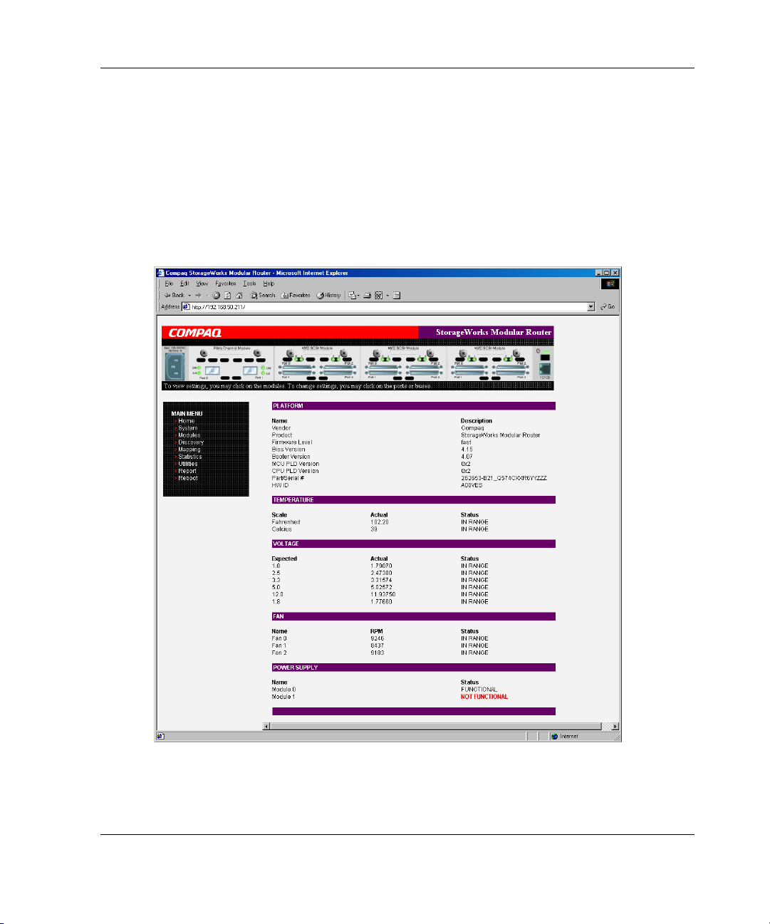
The Main Menu home page is displayed whenever VM is accessed.
The home page contains status information, including a physical image of the
back-side of the router.
Figure 4-1 is an example of the home page.
Visual Manager User Interface
Figure 4-1: Visual Manager home page
StorageWorks by Compaq Network Storage Router M2402 User Guide 4-5
Page 6
Visual Manager User Interface
Home page information includes:
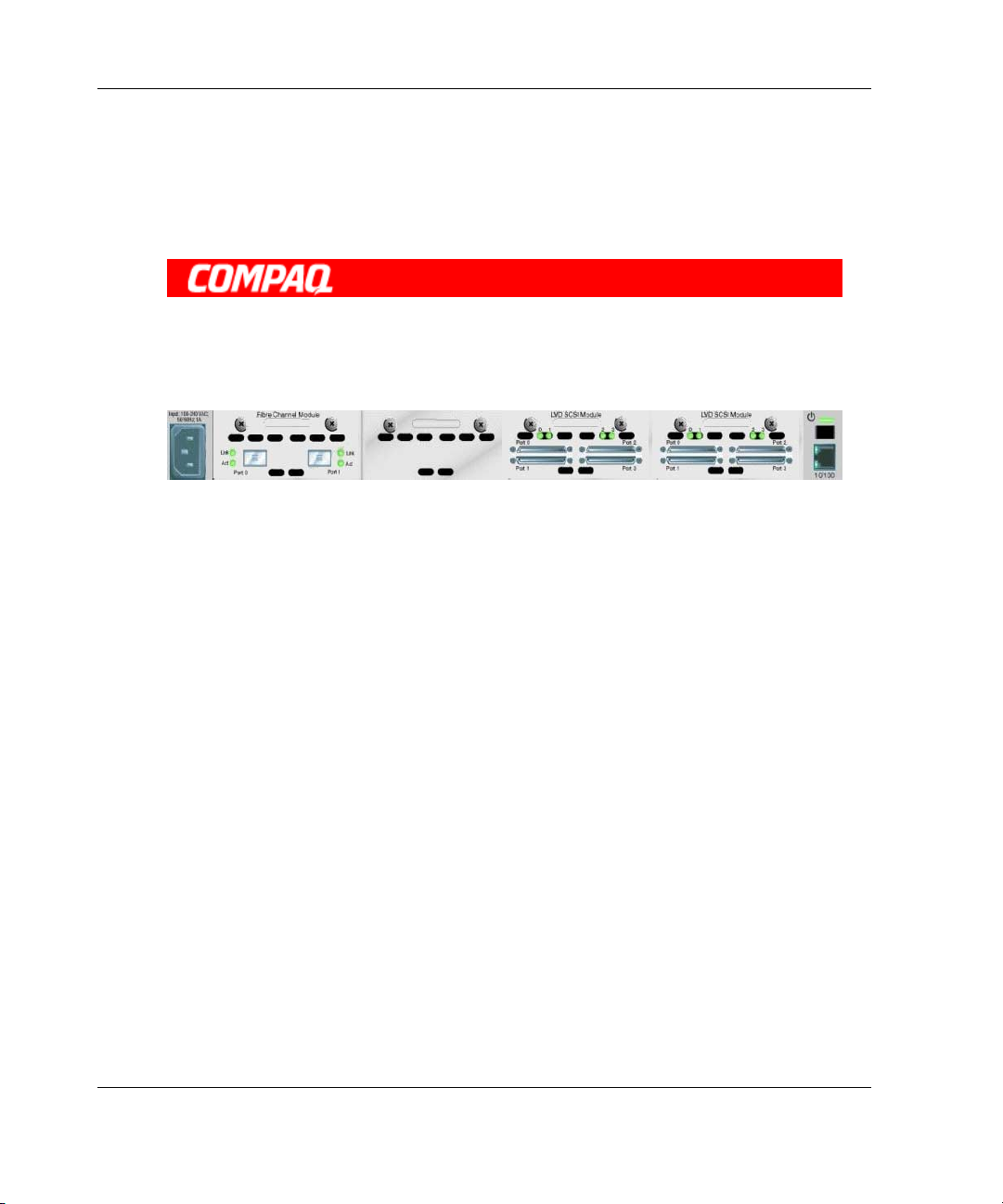
• The Compaq logo is located in the upper left corner of the page. Figure 4-2 is an
example of this portion of the home page screen. If the Internet is accessible to
the host, click the Compaq logo to open the router company Web site.
Figure 4-2: Compaq logo
• A back-side view of the router is located near the top of the home page.
Figure 4-3 is an example of this portion of the home page screen.
Figure 4-3: Back-side router image
The router image is interactive, allowing quick access to configuration menus:
— To display current settings and status for a module, click the corresponding
module shown in the router image.
— To open a menu for making changes to the configuration for that particular
port or bus, click the desired Fibre Channel port or SCSI bus.
— To open the Power Supply Configuration menu, click the power connector
image.
— To open the Network Configuration menu, click the Ethernet port.
— To open the Beacon settings menu, click the System Status LED indicator.
• Router status information is located in the body of the home page and includes:
— Platform information
— Temperature measurements
The home page monitors the temperature of the router, checking once every
60 seconds. If the detected temperature is outside the operating range, a
pop-up notification message indicates that the unit is about to shut down.
NOTE: The temperature warning message appears only on the home page.
4-6 StorageWorks by Compaq Network Storage Router M2402 User Guide
Page 7

Visual Manager User Interface
— Voltage measurements
— Fan measurements
— Power supply functionality
• The Main Menu option bar is located at the left-side of the home page. Use this
option bar to access the configuration menus. Figure 4-4 is an example of this
portion of the home page screen.
Figure 4-4: Main Menu option bar
Main Menu options:
— Home—display router status information.
— System—configure standard system components.
— Modules—configure Fibre Channel and SCSI module ports/buses.
— Discovery—view devices and discover new devices.
— Mapping—view and configure maps.
— Statistics—view router statistics.
— Utilities—configure utility settings.
— Report—view and print system information.
— Reboot —restart the router.
Each Main Menu option is discussed in the following sections of this chapter.
StorageWorks by Compaq Network Storage Router M2402 User Guide 4-7
Page 8
Visual Manager User Interface
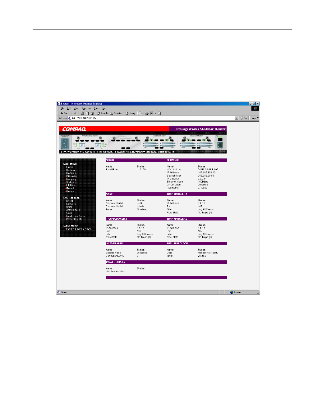
System Menu
The System Menu is accessed from the Main Menu and is used to view and configure
serial, network, SNMP, Trap, Active Fabric, clock, and power supply components.
Figure 4-5 is an example of the System page.
Figure 4-5: System page
4-8 StorageWorks by Compaq Network Storage Router M2402 User Guide
Page 9

Visual Manager User Interface
System Menu tasks:
• Serial configuration—configure the baud rate.
• Network configuration—configure Ethernet settings.
• SNMP configuration—configure SNMP settings.
• Active Fabric configuration—configure Active Fabric settings.
• User configuration—configure user security settings.
• Real-Time Clock configuration—configure system date and time.
• Power Supply configuration—configure the number of power supplies.
• Reset menu—restore factory default settings.
Each menu option is discussed in the following paragraphs.
StorageWorks by Compaq Network Storage Router M2402 User Guide 4-9
Page 10
Visual Manager User Interface
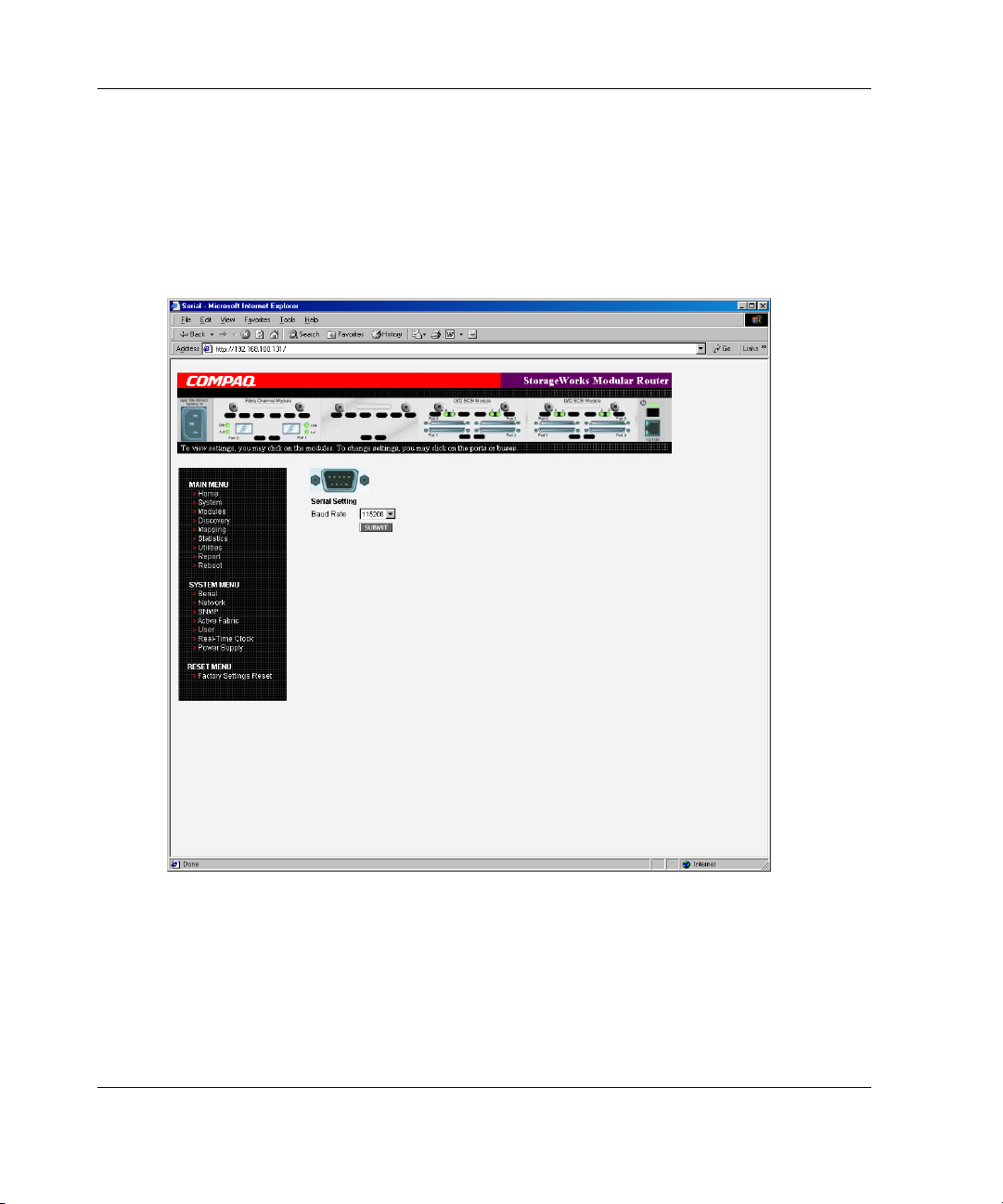
Serial Configuration
The Serial screen is used to change the baud rate for the serial port. Figure 4-6 is an
example of the Serial screen.
If the Autobaud feature is being used, it may not be necessary to set the baud rate.
Figure 4-6: Serial screen
The current baud-rate setting is displayed. Compaq recommends setting this value to
115200.
4-10 StorageWorks by Compaq Network Storage Router M2402 User Guide
Page 11
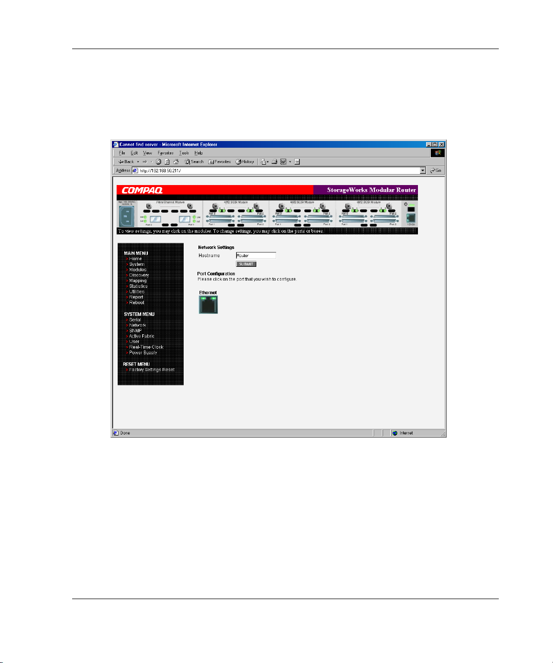
Network Configuration
The Network screen is used to enter network settings, including Ethernet settings.
Figure 4-7 is an example of the Network screen.
Visual Manager User Interface
Figure 4-7: Network screen
Network menu options:
• Network Settings—change the hostname.
• Port Configuration—change Ethernet configuration settings.
StorageWorks by Compaq Network Storage Router M2402 User Guide 4-11
Page 12
Visual Manager User Interface
Network Settings
To change the Hostname, enter an alphanumeric entry of one word up to 8 characters
in length. Click Submit.
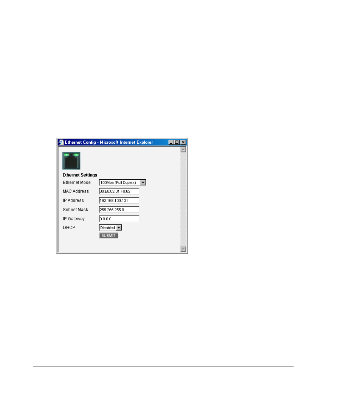
Port Configuration (Ethernet Settings)
To change the Ethernet configuration settings, click the Ethernet port icon.
The Ethernet Configuration dialog box is displayed. See Figure 4-8 for an example of
the Ethernet Configuration dialog box.
Figure 4-8: Ethernet Configuration dialog box
Ethernet configuration settings:
• Ethernet Mode—can be set to one of the following options:
— 10Mps Only
— 100Mps (half duplex) Only
— 100Mps (full duplex) Only
— 10/100Mps (Auto-Neg.)
4-12 StorageWorks by Compaq Network Storage Router M2402 User Guide
Page 13

Visual Manager User Interface
• MAC address—is the Ethernet physical address of the router.
CAUTION: If this configuration setting is incorrectly set, processing difficulties
may occur. Before changing this setting, evaluate the need for the change and
verify the desired setting. Compaq recommends backing up the router
configuration to an external file before making changes to this setting.
The Ethernet physical address is always assigned by the manufacturer.
• IP address—(default: 1.1.1.1) is the IP address of the router.
• Subnet Mask—(default: 255.255.255.0) is the IP subnet mask for the router.
• IP Gateway—(default: 0.0.0.0) is the IP address of the gateway for the Ethernet
network connected to the router.
• DHCP—enables or disables support for Dynamic Host Configuration Protocol
(DHCP).
When DHCP is enabled, the router will request a dynamic IP address from a
DHCP server on the Ethernet network. The router must be rebooted before an IP
address will be requested from the DHCP server. After the router is rebooted, the
HTTP session will have to be restarted. The IP address will be different from the
former non-DHCP IP address.
NOTE: To use the DHCP feature, a DHCP server must be operational on the Ethernet
network. If the DHCP feature is used when there is not DHCP server, the standard for
DHCP requires the router wait thee minutes for a response from a DHCP server before
timing out.
Some DHCP servers allow a lease reservation to be set up for an IP address by
providing the server with the Ethernet MAC address. The DHCP server will then
always provide the same IP address to the router. This setup can be useful for
remote management of the router via Telnet or VM. Because the method of
setting up a lease reservation varies, depending on the DHCP server being used
contact the Network Administrator for assistance.
StorageWorks by Compaq Network Storage Router M2402 User Guide 4-13
Page 14
Visual Manager User Interface
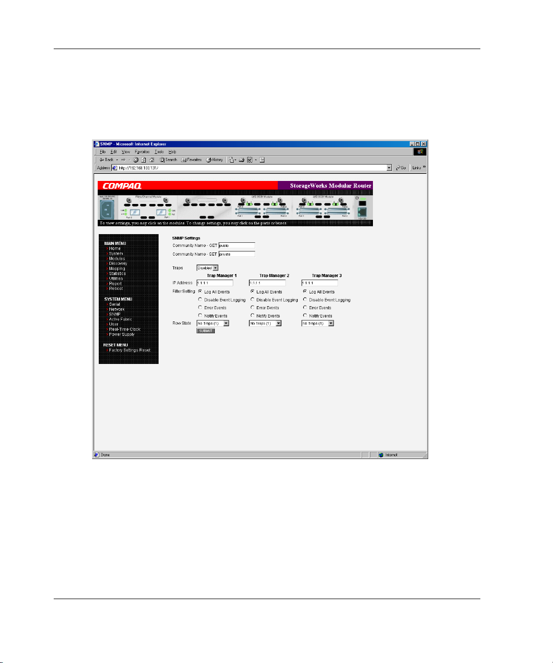
SNMP Configuration
The SNMP screen is used to enter SNMP and Trap settings. Figure 4-9 is an example
of the SNMP screen.
Figure 4-9: SNMP screen
SNMP settings:
• Community Name – GET—(default: public) is checked for each GET request
received by the router.
4-14 StorageWorks by Compaq Network Storage Router M2402 User Guide
Page 15

Visual Manager User Interface
The community name in the SNMP packet must match this community name for
the SNMP GET request to be successfully completed. Configure the SNMP
manager to have the same GET and SET community names as the router.
• Community Name – SET—(default: private) is only applicable for the FA MIB
2.2. See Appendix D “SNMP Management Information Bases” for more
information.
• Traps—enables or disables SNMP traps for manager IP addresses.
If Traps are enabled, up to three Trap Manager IP addresses can be setup.
Trapped events are logged in an event log. Event logging captures up to the last
215 events and then starts overwriting the log.
NOTE: To ensure accurate event logging, verify the clock and date are correctly set in
the Real-Time Clock screen.
• Trap Manager IP Address—is the address used for sending Trap notifications.
Typically, this is the IP address of the machine using the network management
application or MIB browser.
• Trap Manager Filter Setting—sets filtering of event notifications (described in
Appendix D, “SNMP Management Information Bases”).
Event notifications correspond to the trace setting levels configured in the Trace
Settings Configuration menu. The filters that can be set include:
— Log All Events (Priority 0)
— Disable Event Logging (Priority 1)
— Error Events (Priority 6)
— Notify Events (Priority 4)
• Trap Manager Row State—is set to an integer in the range of 0 through 3.
Options include:
— Disabled (0)—clears to the default settings
— No Traps (1)—no traps exist
— Row Exist (2)—row exists but traps are not sent to target.
— Send Traps (3)—row exists and traps are sent.
StorageWorks by Compaq Network Storage Router M2402 User Guide 4-15
Page 16

Visual Manager User Interface
Active Fabric Configuration
The Active Fabric screen allows setup of Active Fabric options. Figure 4-10 is an
example of the Active Fabric screen.
Figure 4-10: Active Fabric screen
4-16 StorageWorks by Compaq Network Storage Router M2402 User Guide
Page 17

Visual Manager User Interface
Active Fabric settings:
• Server-Free Backup Mode—toggles between Enabled and Disabled.
When enabled, server-free backup capability is enabled to allow Extended Copy
commands.
• Number of Controller LUNs—(default: 1) sets the number of controller LUNs
reported by the router.
The number must be in the range of 0 through 4.
NOTE: For Server -Free Backup Mode functionality, if addressing a controller LUN is desired,
at least one controller LUN must be enabled and included in a relevant map.
NOTE: If Server-Free Backup Mode is enabled, Fibre Channel Discovery must be enabled to
allow router access to Fibre Channel Targets.
For information on controller LUN and Extended Copy commands, see Appendix B,
“Controller LUN Commands.”
For general information about server-free backups, see Chapter 1, “Introduction.”
StorageWorks by Compaq Network Storage Router M2402 User Guide 4-17
Page 18

Visual Manager User Interface
User Configuration
The User screen is used to set up router security. Figure 4-11 is an example of the
User screen.
Figure 4-11: User screen
User settings:
• User Name—(default:
• Password—(default:
4-18 StorageWorks by Compaq Network Storage Router M2402 User Guide
root) is any alphanumeric combination.
password) is any alphanumeric combination.
Page 19
The user name and password should be unique and kept confidential. Compaq
recommends using a combination of letters and numbers when creating the user name
and password.
NOTE: These security settings affect all user interfaces of the router.
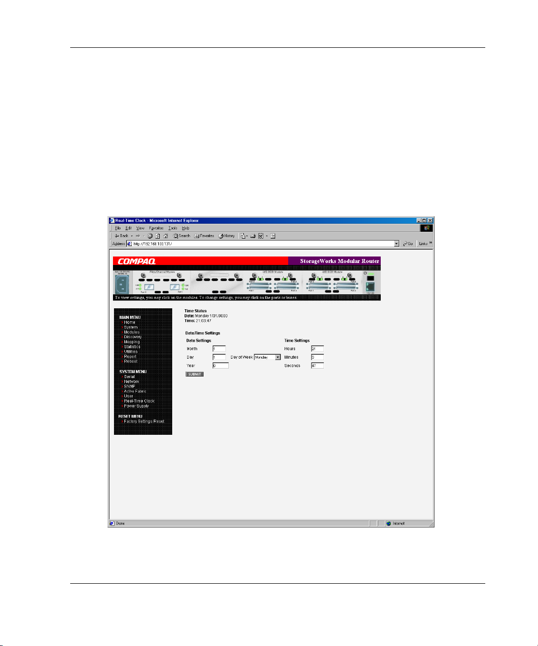
Real-Time Clock Configuration
The Real Time Clock screen is used to set the system time and date. Figure 4-12 is an
example of the Real-Time Clock screen.
Visual Manager User Interface
Figure 4-12: Real-Time Clock screen
StorageWorks by Compaq Network Storage Router M2402 User Guide 4-19
Page 20

Visual Manager User Interface
Real-Time Clock settings:
• Date Settings—sets the month, date, and year.
Use a four-digit number to represent the year.
• Day of Week—sets the day of week.
• Time Settings—sets the hours, minutes, and seconds.
This is a 24-hour clock.
Power Supply Configuration
The Power Supply screen is used to indicate the number of power supplies installed
in the router.
The router is shipped with one installed power supply, but a redundant power supply
can be purchased.
If two power supplies are installed in the router, use this screen to indicate the
change.
Figure 4-13 is an example of the Power Supply screen.
When set to 1, the router suppresses event notifications of the second power supply.
NOTE: If set to ‘1’ in a two-power-supply configuration, the router cannot issue an event
notification if one of the power supplies fails.
NOTE: If there are two power supplies, and one of the two fails, this option does not inhibit the
router from using the second power supply.
4-20 StorageWorks by Compaq Network Storage Router M2402 User Guide
Page 21

Visual Manager User Interface
Figure 4-13: Power supply screen
StorageWorks by Compaq Network Storage Router M2402 User Guide 4-21
Page 22

Visual Manager User Interface
Reset Menu
The Reset Menu is used to reset the router to factory default settings. Figure 4-14 is
an example of the Reset Menu.
Figure 4-14: Reset to Factory Default screen
Current router activities will be disrupted while the unit resets the configuration to
the factory defaults and saves those options to FLASH memory.
NOTE: Resetting to factory defaults through VM will not affect Ethernet connectivity.
User-configured values for the IP address and gateway will be retained.
4-22 StorageWorks by Compaq Network Storage Router M2402 User Guide
Page 23
Modules Menu
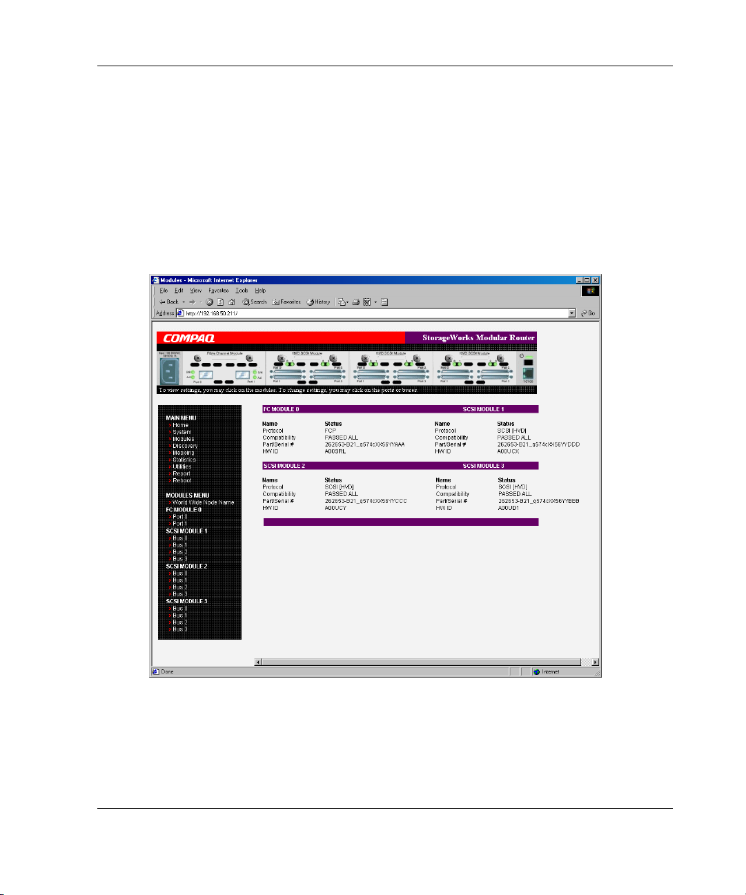
Accessed from the Main Menu, the Modules Menu is used to view and modify
configuration settings of Fibre Channel and SCSI modules.
The initial screen display of the Modules Menu includes summary information about
each Fibre Channel and SCSI module in the router.
See Figure 4-15 for an example of the initial Modules Menu.
Visual Manager User Interface
Figure 4-15: Modules menu
StorageWorks by Compaq Network Storage Router M2402 User Guide 4-23
Page 24

Visual Manager User Interface
NOTE: To view or change configuration settings of a specific module, select one of the
options from the menu bar on the left side of the screen or select a module or port from the
router image at the top of the screen.
To make changes, modify the setting and then click Submit.
Modules Menu tasks:
• World Wide Node Name configuration—change World Wide Node Name.
• Fibre Channel Module configuration—change Fibre Channel module settings.
• SCSI Module configuration—change SCSI module settings.
Each Modules Menu option is discussed in the following sub-sections.
World Wide Node Name Configuration
The World Wide Node (WWN) Name screen is used to change the WWN Name
settings for the router.
Figure 4-16 is an example of the World Wide Node Name screen.
These WWN settings are not normally changed.
CAUTION: Changing the WWN Name could result in duplicate names on a single
Storage Area Network (SAN). Compaq recommends using the default values for
World Wide Names.
NOTE: For Controller LUN commands to be operational, WWN naming schemes MUST be
compliant with IEEE Fibre Channel Format 1, where the left-most hexadecimal character (the
NAA field) of the WWN is '1'. Further, the sixth hexadecimal value from the right must be a
value of '0' or'1'.
NOTE: If the configuration settings are reset to the factory default, these customized WWN
settings will be overwritten.
4-24 StorageWorks by Compaq Network Storage Router M2402 User Guide
Page 25

Visual Manager User Interface
Figure 4-16: World Wide Node Name screen
StorageWorks by Compaq Network Storage Router M2402 User Guide 4-25
Page 26

Visual Manager User Interface
Fibre Channel Module Configuration
When a Fibre Channel module is selected in Modules Menu, the Fibre Channel
Module status screen is displayed. Summary information for each Fibre Channel port
of the Fibre Channel module is displayed. Figure 4-17 is an example of the Fibre
Channel Module screen.
Figure 4-17: Fibre Channel module status screen
The Fibre Channel Module screen is used to view and modify Fibre Channel module
configuration settings. To change settings for one of the Fibre Channel ports, select
the desired port of the Fibre Channel module on the menu bar or on the router image.
Figure 4-18 is an illustration of the Fibre Channel module on the router image.
4-26 StorageWorks by Compaq Network Storage Router M2402 User Guide
Page 27

Visual Manager User Interface
Figure 4-18: Fibre Channel module image
After a port on the Fibre Channel module is selected, the following screen is
displayed to enter configuration changes. Figure 4-19 is an example of the FC
Module Port Configuration Settings screen.
Figure 4-19: Fibre Channel module port configuration
settings screen
StorageWorks by Compaq Network Storage Router M2402 User Guide 4-27
Page 28

Visual Manager User Interface
Fibre Channel module port settings:
• Link Status—indicates the port link status.
• Port Name High—sets a new value for the World Wide Port Name High.
CAUTION: If this configuration setting is incorrectly set, processing difficulties
may occur. Before changing this setting, evaluate the need for the change and
verify the desired setting. Compaq recommends backing up the router
configuration to an external file before making changes to this setting.
• Port Name Low—sets a new value for the World Wide Port Name High.
CAUTION: If this configuration setting is incorrectly set, processing difficulties
may occur. Before changing this setting, evaluate the need for the change and
verify the desired setting. Compaq recommends backing up the router
configuration to an external file before making changes to this setting.
• Port Mode—(default: N_Port) sets the port mode.
Port Mode settings:
— Auto Sense—In this mode, the Fibre Channel port tries to negotiate as a
loop. If it is not successful, then the Fibre Channel port negotiates as a fabric.
If the port comes up as a loop, it then determines whether it is on a private or
public loop.
— N_Port—(default) This mode allows the router to bypass the loop
negotiation and come up as a fabric only. If the router is on a loop, and
N_Port mode is selected, an error in communication may occur.
• Use Hard AL_PA—enables or disables Hard AL_PA usage.
• Hard AL_PA Settings—When Hard AL_PA usage is enabled, select Set
AL_PA Settings to display the AL_PA Lookup Table.
Use the table to find the node number. This unique one-byte valid value (derived
from an Arbitrated Loop Topology defined in ANSI specification FC_AL version
4.5) is used for the Fibre Channel configuration.
Figure 4-20 is an illustration of the AL_PA table.
4-28 StorageWorks by Compaq Network Storage Router M2402 User Guide
Page 29

Visual Manager User Interface
Figure 4-20: AL_PA lookup table
StorageWorks by Compaq Network Storage Router M2402 User Guide 4-29
Page 30

Visual Manager User Interface
• Discovery Mode—(default: auto discovery on reboot events) determines how the
router will discover new Fibre Channel devices.
Discovery Mode settings:
— Auto Discovery on Reboot Events—(default) allows the router to
automatically discover all Fibre Channel devices when rebooted or when
link-up events occur, such as connecting cables or rebooting network hubs.
Both the ports and the devices behind the ports are discovered on all
subsequent link-up events.
— Auto Discovery on Link Up Events—allows the router to automatically
discover all Fibre Channel devices when rebooted or when link-up events
occur, such as connecting cables or rebooting network hubs.
Both the ports and the devices behind the ports are discovered for the first
link-up event. Subsequent link-up events will only discover the ports and not
the devices behind the ports.
— Manual Discovery Only—sets discovery of new devices to only occur after
the user selects the Discovery option from the Main Menu or when a
Registered State Change Notification (RSCN) is received from a fabric.
NOTE: SCSI devices attached to a Fibre Channel must be mapped as sequential Fibre
Channel LUNs starting at LUN number 00. Skipping LUN numbers is not recommended
when mapping Fibre Channel LUNs because Fibre Channel Discovery stops the
discovery process whenever an empty LUN position is found.
• Buffered Tape Writes—(default: enabled) enables or disables the Buffered
Tape Writes option.
CAUTION: If this configuration setting is incorrectly set, processing difficulties
may occur. Before changing this setting, evaluate the need for the change and
verify the desired setting. Compaq recommends backing up the router
configuration to an external file before making changes to this setting.
When enabled, to enhance performance, Buffered Tape Writes return status on
consecutive write commands prior to the tape device receiving data.
• Buffered Tape Queue Depth—sets the Buffered Tape Queue Depth.
Select a setting of 0 through 10 from the drop-down list.
4-30 StorageWorks by Compaq Network Storage Router M2402 User Guide
Page 31

Visual Manager User Interface
• Default Map—(default: auto-assigned) sets the current mapping mode for the
selected port.
The current map can be set to:
— Indexed
— Auto-assigned—(default) contains all the SCSI devices that are attached to
the router.
— SCC
For more information about mapping modes, see Appendix C, “Addressing
Methods and Table Structures.”
For information on changing map settings, see “Mapping Menu” later in this
chapter.
• Performance Mode—(default: 1 Gb/s) toggles between 1 Gb/s and 2 Gb/s.
NOTE: If set incorrectly and the router is plugged into a Loop or Fabric, the unit may
receive Framing errors due to the incorrect Fibre Channel link speed.
• Override Settings—enhances interoperability with some storage devices that
require special consideration during setup of the router configuration menus.
CAUTION: If these configuration settings are incorrectly set, processing
difficulties may occur. Before changing these settings, evaluate the need for the
change and verify the desired setting. Compaq recommends backing up the
router configuration to an external file before making changes to this setting.
— Hi-Sup Bit—toggles between Set and Clear.
— Force FCP Response Code—toggles between Off and On for support of
Compaq-specific HBA #223180-B21 and #120186-001.
— Initiator Bit—toggles between Set and Clear.
When using the router in a router-to-router configuration, this option should
be configured to Set. A router-to-router configuration is a type of
configuration where one router appears as a target to another initiator router.
— Link Garbage Deletion—toggles between Enabled and Disabled.
StorageWorks by Compaq Network Storage Router M2402 User Guide 4-31
Page 32

Visual Manager User Interface
SCSI Module Configuration
When a SCSI module is selected in the Modules Menu, the SCSI Module status
screen is displayed. (Figure 4-21) is an illustration of the SCSI Module status screen.
Figure 4-21: SCSI Module status screen
The SCSI Module status screen is used to view and modify SCSI module settings.
Summary information for each SCSI bus of the SCSI module is displayed.
To change settings for one of the SCSI buses, select the desired bus of the SCSI
module on the menu bar or on the router image.
4-32 StorageWorks by Compaq Network Storage Router M2402 User Guide
Page 33

Visual Manager User Interface
Figure 4-22 is an illustration of the SCSI module on the router image.
Figure 4-22: SCSI module image
After a bus on the SCSI module is selected, the SCSI Module Bus Configuration
Settings screen is displayed to enter configuration changes. See Figure 4-23.
Figure 4-23: SCSI Module Bus Configuration Settings
screen
StorageWorks by Compaq Network Storage Router M2402 User Guide 4-33
Page 34

Visual Manager User Interface
SCSI module bus settings:
• Primary Initiator ID—(default: 7) must be a unique ID.
• Alternate Initiator ID—(default: none) will be used if the primary ID is taken.
Must be a unique ID.
CAUTION: If this configuration setting is incorrectly set, processing difficulties
may occur. Before changing this setting, evaluate the need for the change and
verify the desired setting. Compaq recommends backing up the router
configuration to an external file before making changes to this setting.
• Target ID(s)—adds or removes Target IDs.
CAUTION: If this configuration setting is incorrectly set, processing difficulties
may occur. Before changing this setting, evaluate the need for the change and
verify the desired setting. Compaq recommends backing up the router
configuration to an external file before making changes to this setting.
NOTE: Target IDs must be setup prior to mapping devices on the SCSI bus.
NOTE: Do not enable Target IDs unless there is a SCSI initiator on the bus that wants to
use Fibre Channel devices. This type of configuration is known as a Target Mode
configuration.
• Discovery—toggles between Enabled and Disabled.
• Discovery Delay—is the wait time after a power-up or reboot before discovering
SCSI devices.
NOTE: Compaq recommends setting the value to at least 2 seconds to ensure all SCSI
devices complete their individual power-ups.
• Bus Reset on Boot—toggles between Enabled and Disabled.
When enabled, the router will automatically reset SCSI buses during a power up
or reboot of the router.
4-34 StorageWorks by Compaq Network Storage Router M2402 User Guide
Page 35

Visual Manager User Interface
• Internal Termination—toggles between Enabled and Disabled.
CAUTION: If this configuration setting is incorrectly set, processing difficulties
may occur. Before changing this setting, evaluate the need for the change and
verify the desired setting. Compaq recommends backing up the router
configuration to an external file before making changes to this setting.
When enabled, allows internal termination of the selected SCSI bus. When
disabled, the SCSI Bus, not the router handles SCSI termination.
• Buffered Tape Writes—(default: Enabled) toggles between Enabled and
Disabled.
When enabled, Buffered Tape Writes enhance system performance. Buffered
Tape Writes return status on consecutive write commands prior to the tape device
receiving data.
• Default Map—(default: auto-assigned) sets the current mapping mode for the
selected bus.
CAUTION: If this configuration setting is incorrectly set, processing difficulties
may occur. Before changing this setting, evaluate the need for the change and
verify the desired setting. Compaq recommends backing up the router
configuration to an external file before making changes to this setting.
The current map can be set to:
— Indexed
— Auto-assigned (default)—contains all the devices attached to the router.
— SCC
For more information about mapping modes, see Appendix C, “Addressing
Methods and Table Structures.”
For information on changing map entries, see “Mapping Menu” later in this
chapter.
• Override Settings—To override the settings of a SCSI target, select a Target ID
icon with the appropriate Target ID number.
After a specific Target is selected, the SCSI Override sub-screen is displayed and
is used to enter the Override settings. See Figure 4-24 for an illustration of the
SCSI Override screen.
StorageWorks by Compaq Network Storage Router M2402 User Guide 4-35
Page 36

Visual Manager User Interface
CAUTION: If this configuration setting is incorrectly set, processing difficulties
may occur. Before changing this setting, evaluate the need for the change and
verify the desired setting. Compaq recommends backing up the router
configuration to an external file before making changes to this setting.
Figure 4-24: SCSI Device Override screen
4-36 StorageWorks by Compaq Network Storage Router M2402 User Guide
Page 37

Visual Manager User Interface
SCSI bus override settings:
— CDB Length Override—enables or disables the override of default CDB
lengths.
— CDB Group 6 Length Default—(default: 0) can be set to 0, 6, 10, or 12.
— CDB Group 7 Length Default—(default: 0) can be set to 0, 6, 10, or 12.
— Wide Negotiation—enables or disables negotiation on a wide SCSI bus.
— Synchronous Negotiation—enables or disables synchronous negotiation on
the SCSI bus.
— Synchronous Parameter Override—enables or disables parameters for
synchronous negotiation.
— Synchronous Period—(default: 40) sets the maximum number of seconds
allowed for negotiation.
— Synchronous Offset—(default: 16) sets the maximum variation in transfer
rate that can be negotiated in megabytes per seconds (MB/s).
— Ultra SCSI-3 Negotiation—enables or disables Ultra SCSI-3 support for the
selected Target ID.
When enabled, Ultra SCSI-3 Negotiation helps solve certain compatibility
issues in mixed vendor environments where there may be a device that
cannot handle automatic negotiation of the bus speed or where there is a
device that negotiates to use Ultra SCSI-3 but cannot handle the speed.
StorageWorks by Compaq Network Storage Router M2402 User Guide 4-37
Page 38

Visual Manager User Interface
Discovery Menu
Accessed from the Main Menu, the Discovery Menu is used to view Target devices
and discover new Target devices.
Figure 4-25 is an example of the Discovery page.
Figure 4-25: Discovery page
In the Discovery Menu, select a specific Fibre Channel Port or SCSI bus from the
Menu Bar or the router image and then click Go.
4-38 StorageWorks by Compaq Network Storage Router M2402 User Guide
Page 39

Mapping Menu
Accessed from the Main Menu, the Mapping Menu is used to view and modify host
and map information for a Fibre Channel port or SCSI bus. Maps and hosts may be
added, edited, or deleted.
The initial screen display lists all available hosts and the assigned map for the
selected Fibre Channel port or SCSI bus.
Figure 4-26 is an example of the initial Mapping screen.
Visual Manager User Interface
Figure 4-26: Mapping screen
StorageWorks by Compaq Network Storage Router M2402 User Guide 4-39
Page 40

Visual Manager User Interface
To view or change map settings of a specific module:
1. Select one of the module and port/bus from the menu bar on the left side of the
screen or from the router image at the top of the screen.
2. After a Fibre Channel port or SCSI bus has been selected, specific mapping
information is displayed, including the name of the port, the selected host, and
the assigned map.
3. To make changes to the configuration, enter the new value and then click
Submit.
Because many mapping configuration settings are common to Fibre Channel and
SCSI maps, this section is subdivided as follows:
• Fibre Channel and SCSI Common Mapping Tasks
• Fibre Channel Mapping Tasks
• SCSI Mapping Tasks
Fibre Channel and SCSI Common Mapping Tasks
The following action options are available for Fibre Channel and SCSI maps:
• Add Host—adds a new host.
To add an undefined host, type the hostname in the Add Host field and then click
Add.
• Add Map—adds a new map.
To add an undefined map, type the name of the map in the Add Map field and
then click Add.
• Select Host—adds a known host.
To select a previously set up host, expand the Select Host drop-down box and
select the host from the list.
• Select Map—adds a known map.
To select a previously set up map, expand the Select Map drop-down box and
select the map from this list.
4-40 StorageWorks by Compaq Network Storage Router M2402 User Guide
Page 41

Visual Manager User Interface
• Delete Host—deletes the current host.
NOTE: ‘Built at runtime’ hosts cannot be deleted.
• Delete Map—deletes the current map.
NOTE: ‘Indexed’, ‘Auto Assigned’, and ‘SCC’ maps cannot be deleted or renamed.
• Edit/View Host—view or change host information.
Viewing and changing Host information is discussed in the following paragraphs.
• Edit/View Map—view or change map information.
Viewing and changing Map information is discussed in the following paragraphs.
• Clone Map—makes a copy of the Current map.
Cloning makes it easier to setup new maps with similar information to previously
created maps. The new map must have a unique map ID and name.
NOTE: SCC and Auto-Assigned maps cannot be cloned.
Fibre Channel Mapping Tasks
Configuration tasks for Fibre Channel mapping include:
• Viewing and Changing Fibre Channel Host Information
• Viewing and Changing Fibre Channel Map Information
Each task is discussed in the following paragraphs.
Viewing and Changing Fibre Channel Host Information
To view or change current host information:
1. In the Mapping Menu screen, select the desired Fibre Channel module and port.
2. Click Edit/View in the Host section of the screen.
The Fibre Channel Host Name dialog box is displayed. Current host information
is shown at the top of the dialog box.
StorageWorks by Compaq Network Storage Router M2402 User Guide 4-41
Page 42

Visual Manager User Interface
3. Enter the new settings and then click Modify.
Figure 4-27 is an example of the Fibre Channel Host Name dialog box.
Figure 4-27: Fibre Channel Host Name dialog box
Fibre Channel Host Name settings:
• Host Name
• Host ID (hexadecimal)
• Port WWN Hi (hexadecimal)
• Port WWN Lo (hexadecimal)
• Node WWN Hi (hexadecimal)
• Node WWN Lo (hexadecimal)
• Map Name
4-42 StorageWorks by Compaq Network Storage Router M2402 User Guide
Page 43

Viewing and Changing Fibre Channel Map Information
To view or change current Fibre Channel map host information:
1. In the Mapping Menu screen, select the desired Fibre Channel module and port.
2. Click Edit/View in the Map section of the screen.
The Fibre Channel Map dialog box is displayed. Current map information is
shown at the top of the dialog box.
3. Enter the new settings and then click the appropriate action button.
Figure 4-28 is an example of the Fibre Channel Map dialog box.
Visual Manager User Interface
Figure 4-28: Fibre Channel Map dialog box
NOTE: Auto-Assigned and SCC maps cannot be modified, cleared, filled, or have entries
removed.
StorageWorks by Compaq Network Storage Router M2402 User Guide 4-43
Page 44

Visual Manager User Interface
NOTE: Map settings are saved to memory when any of the buttons within the page are
selected.
Fibre Channel Map settings:
• Clear Map—clears all entries from the current map.
• Remove Gaps—removes any incremental gaps in the sequence of LUN listed in
the table.
When the system removes gaps from the table, the LUN are renumbered in
sequential order, starting with LUN 0.
NOTE: Some operating systems require gaps be removed in the mapping table in order
to detect all devices.
• Fill Map—fills in the current map.
To use the Fill Map option, expand the Fill Map Priority drop-down box, select
the fill option, and then click Fill Map.
When the map is filled, the display will show the current devices.
• Delete—deletes map entries.
To delete map entries, expand the Delete Map Item LUN drop-down box, select
the LUN, and then click Delete.
To delete a range of LUNs, select the beginning LUN to delete from the ‘from’
drop-down box and select the last LUN to delete from the ‘to’ drop-down box.
• Discovered Device Entry—adds a discovered device to the map.
To add a discovered device to the map, use the drop-down boxes to enter the
settings, and then click Create Entry in the Discovered Device Entry section of
the screen.
• Manual Device Entry—create a map entry for a device that is not yet
discovered or installed.
To add a new device to the map, use the drop-down boxes to enter the settings,
and then click Create Entry in the Manual Device Entry section of the screen.
4-44 StorageWorks by Compaq Network Storage Router M2402 User Guide
Page 45

SCSI Mapping Tasks
Configuration tasks for SCSI mapping include:
• Viewing and Changing SCSI Host Information
• Viewing and Changing SCSI Map Information
Each task is discussed in the following paragraphs.
Viewing and Changing SCSI Host Information
To view or change current SCSI host information:
1. In the Mapping Menu screen, select the desired SCSI module and bus.
2. Click Edit/View in the Host section of the screen.
The SCSI Host Name dialog box is displayed. Current host information is shown
at the top of the dialog box.
3. Enter the new settings and then click Modify.
Visual Manager User Interface
Figure 4-29 is an example of the SCSI Host Name configuration dialog box.
StorageWorks by Compaq Network Storage Router M2402 User Guide 4-45
Page 46

Visual Manager User Interface
Figure 4-29: SCSI Host Name dialog box
SCSI Host Name settings:
• Host Name
• Initiator ID
• Map Name
4-46 StorageWorks by Compaq Network Storage Router M2402 User Guide
Page 47

Viewing and Changing SCSI Map Information
To view or change current SCSI map host information:
1. In the Mapping Menu screen, select the desired SCSI module and bus.
2. Click Edit/View in the Map section of the screen.
The SCSI Map dialog box is displayed. Current map information is shown at the
top of the dialog box.
3. Enter the new settings and then click the appropriate action button.
Figure 4-30 is an example of the SCSI Map dialog box.
Visual Manager User Interface
Figure 4-30: SCSI Map dialog box
NOTE: To map Fibre Channel devices to any SCSI initiator on the selected bus, a Target ID
must be enabled from the SCSI Bus Configuration Menu. A Target ID should only be added if
there is a SCSI initiator that needs to address Fibre Channel devices. Each Target ID can be
used to store up to 32 Fibre Channel devices.
StorageWorks by Compaq Network Storage Router M2402 User Guide 4-47
Page 48

Visual Manager User Interface
NOTE: Auto-Assigned and SCC maps cannot be modified, cleared, filled, or have entries
deleted.
NOTE: Map settings are saved to memory when any button within the page is selected.
SCSI Map settings:
• Clear Map—clears all entries from the current map.
• Fill Map—fills in the current map.
When the map is filled, the display will show the current devices.
• Remove Gaps—removes any incremental gaps in the sequence of LUN listed in
the table.
When the system removes gaps from the table, the LUN are renumbered in
sequential order, starting with LUN 0.
NOTE: Some operating systems require gaps be removed in the mapping table to detect
all devices.
• Delete—deletes map entries.
To delete a range of LUNs, select the beginning LUN to delete from the ‘from’
drop-down box and select the last LUN to delete from the ‘to’ drop-down box.
• Discovered Device Entry—adds a discovered device to the map.
To add a discovered device to the map, use the drop-down boxes to enter the
settings, and then click Create Entry in the Discovered Device Entry section of
the screen.
• Manual Device Entry—creates a map entry for a device that is not yet
discovered or installed.
To add a new device to the map, use the drop-down boxes to enter the settings,
and then click Create Entry in the Manual Device Entry section of the screen.
NOTE: SCSI maps can be filled or devices can be added to them only when at least one
SCSI Target ID has been enabled in the SCSI bus configuration menu.
4-48 StorageWorks by Compaq Network Storage Router M2402 User Guide
Page 49

Statistics Menu
Accessed from the Main Menu, the Statistics Menu is used to display Fibre Channel
port and SCSI bus information. Figure 4-31 is an example of the Statistics Menu.
Visual Manager User Interface
Figure 4-31: Statistics Menu
To view information for a specific module port/bus, click the component on menu
bar or the router image.
To reset the statistics, click Go.
StorageWorks by Compaq Network Storage Router M2402 User Guide 4-49
Page 50

Visual Manager User Interface
Utilities Menu
Accessed from the Main Menu, the Utilities Menu is used to view and configure
utility options.
Figure 4-32 is an example of the Utilities Menu.
Figure 4-32: Utilities menu
4-50 StorageWorks by Compaq Network Storage Router M2402 User Guide
Page 51

Visual Manager User Interface
Utility Menu tasks:
• Beacon configuration—enable the Beacon mode.
• FTP Utility access—open an FTP session.
• Trace Settings configuration—configure trace settings.
• Current Traces display—view current trace information.
• Previous Traces display—view previous trace information.
• Last Assert Traces display—view last assert trace information.
• Clear Current Traces—clear current trace information.
• Clear Assert Traces—clear current trace information.
• Event Log Settings—configure Event Log settings.
• Event Log display—view the Event Log.
• Clear Event Log—clear the Event Log.
Each Utility Menu option is discussed in the following sections.
Beacon Mode Configuration
The Beacon Configuration screen is used to enable and disable the router Beacon
mode. When enabled, the Power LED located on the back-side of the router will
continuously blink, alternating between amber and green.
To enable the Beacon settings, select the ON checkbox and then click Submit.
Figure 4-33 is an example of the Beacon settings screen.
StorageWorks by Compaq Network Storage Router M2402 User Guide 4-51
Page 52

Visual Manager User Interface
Figure 4-33: Beacon configuration screen
NOTE: When the router is rebooted, Beaconing is automatically disabled.
4-52 StorageWorks by Compaq Network Storage Router M2402 User Guide
Page 53

FTP Utility Access
The FTP Utility screen is used to open an FTP session. Figure 4-34 is an example of
the FTP Utility screen.
Visual Manager User Interface
Figure 4-34: FTP Utility screen
The FTP Utility requires the use of a JAVA applet and prompts for permission to
install the applet, if needed. If the prompt is displayed, follow the onscreen
instructions to complete the installation. The FTP Utility then prompts for permission
to run the applet.
StorageWorks by Compaq Network Storage Router M2402 User Guide 4-53
Page 54

Visual Manager User Interface
NOTE: Internet access is required to verify the signature for the Compaq FTP applet and to
download the JAVA applet plug-in for your browser.
To open an FTP session:
1. Enter the User Name, Password, and the IP address of the router.
2. Click Connect.
3. Select the local file to upload or download. If necessary, click Browse to scroll
through a file list.
The following file types can be uploaded to the router:
• Configuration (.cfg)
• Firmware (.dlx)
The following file types can be downloaded from the router:
• Configuration (.cfg)
• Traces for the current boot cycle (curtrace.txt)
• Traces from the previous boot cycle (prvtrace.txt)
4. Click Binary Transfer mode.
5. To download a file, click Get.
6. To upload a file, click Put.
NOTE: If a valid firmware or configuration file is uploaded to the router, an automatic reboot
will occur once the file has been received. The router cannot be accessed from the Visual
Manager UI during the time that the reboot is in process, which is approximately 30 seconds.
4-54 StorageWorks by Compaq Network Storage Router M2402 User Guide
Page 55

Trace Settings Configuration
The Trace Settings screen is used to configure the trace settings. Figure 4-35 is an
example of the Trace Settings screen.
Visual Manager User Interface
Figure 4-35: Trace Settings screen
Current Trace settings are displayed.
To change the settings, use the drop-down boxes and select the desired setting. After
all changes are completed, click Submit.
Table 4-1 is a brief description list of the trace settings.
StorageWorks by Compaq Network Storage Router M2402 User Guide 4-55
Page 56

Visual Manager User Interface
Table 4-1: Trace Settings
General Errors Displays the most serious errors
FCP Transport Fibre Channel Protocol transport
PS Transport Parallel SCSI transport functionality
PS Driver Parallel SCSI driver functionality will
Timing Timer functions will be monitored
AF Active Fabric firmware will be
FCP Driver Fibre Channel Protocol driver
FCP Management Fibre Channel Protocol
PS Management Parallel SCSI functionality will be
SG List Scatter/gather list will be monitored
FCP/RMI Fibre Channel Protocol routing layer
INBAND Controller management functionality
and exception conditions.
functionality will be monitored and
recorded.
will be monitored and recorded.
be monitored and recorded.
and recorded.
monitored and recorded.
functionality will be monitored and
recorded.
management functionality will be
monitored and recorded.
monitored and recorded.
and recorded
will be monitored and recorded.
will be monitored and recorded.
4-56 StorageWorks by Compaq Network Storage Router M2402 User Guide
Page 57

Visual Manager User Interface
Current, Previous, and Last Assert Trace Displays
These three Utilities Menu screens show trace information. The Current Traces
screen shows data since the router was last booted. The Previous Traces screen shows
data from the last boot cycle. The Last Assert Traces screen shows data since the last
assertion.
Figure 4-36 is an example of the Current Traces screen.
Figure 4-36: Current Traces screen
StorageWorks by Compaq Network Storage Router M2402 User Guide 4-57
Page 58

Visual Manager User Interface
Clear Current Traces and Clear Assert Traces
These Utilities Menu screens are used to clear the current trace buffer or the assert
trace buffer.
Current router activities will not be disrupted while the buffer is cleared.
Figure 4-37 is an example of the Clear Current Trace Buffer screen.
Figure 4-37: Clear Current Trace Buffer screen
4-58 StorageWorks by Compaq Network Storage Router M2402 User Guide
Page 59
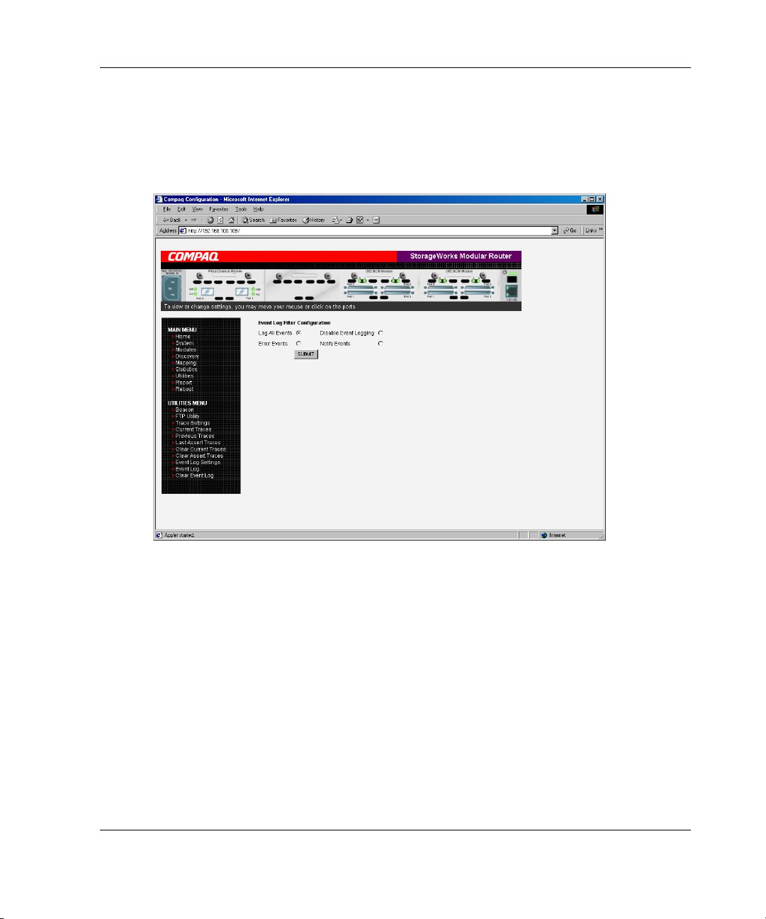
Event Log Configuration
The Event Log Setting screen is used to configure Event Log filters. Figure 4-38 is an
example of the Event Log Filter configuration screen.
Visual Manager User Interface
Figure 4-38: Event Log settings screen
Event Log settings:
• Log All Events
• Disable/Enable Event Logging
• Log Error Events
• Log Notify Events
Event logging captures the last 215 events and then starts overwriting the log.
StorageWorks by Compaq Network Storage Router M2402 User Guide 4-59
Page 60

Visual Manager User Interface
NOTE: To ensure accurate event logging, be sure to correctly set the clock and date in the
Real Time Clock Configuration menu.
Event Log Display
The Event Log screen is used to view the Event Log. Figure 4-39 is an example of
the Event Log display screen.
Figure 4-39: Event Log display screen
4-60 StorageWorks by Compaq Network Storage Router M2402 User Guide
Page 61

Clear Event Log
The Clear Event Log screen is used to clear the Event Log. Figure 4-40 is an example
of the Clear Event Log screen.
Current router activities will not be disrupted.
Visual Manager User Interface
Figure 4-40: Clear Event Log screen
StorageWorks by Compaq Network Storage Router M2402 User Guide 4-61
Page 62

Visual Manager User Interface
Report Menu
Accessed from the Main Menu, the Report page displays a consolidated view of all
system information, including environmental conditions. Figure 4-41 is an example
of the Report page.
To print the system information, click Printable View.
Figure 4-41: Report screen
4-62 StorageWorks by Compaq Network Storage Router M2402 User Guide
Page 63

Reboot Option
Router reboots are executed using this router Main Menu option. Figure 4-42 is an
example of the Reboot screen.
When the router is rebooted, current router activities will be disrupted. All submitted
configuration changes will be activated during the boot-up process.
Visual Manager User Interface
Figure 4-42: Reboot screen
StorageWorks by Compaq Network Storage Router M2402 User Guide 4-63
 Loading...