

Page 1

Notice
The information in this guide is subject to change without notice.
Compaq Computer Corporation shall not be liable for technical or editorial
errors or omissions contained herein; nor for incidental or consequential
damages resulting from the furnishing, performance, or use of this
material.
This guide contains information protected by copyright. No part of this
guide may be photocopied or reproduced in any form without prior written
consent from Compaq Computer Corporation.
Copyright 1994 Compaq Computer Corporation.
All rights reserved. Printed in the U.S.A.
Compaq, Deskpro, LTE, Contura
Registered U.S. Patent and Trademark Office.
LTE Elite, SmartStation, and MiniStation are trademarks of Compaq Computer
Corporation.
Microsoft and MS-DOS are registered trademarks of Microsoft Corporation.
Windows is a trademark of Microsoft Corporation.
The software described in this guide is furnished under a license agreement
or nondisclosure agreement. The software may be used or copied only in
accordance with the terms of the agreement.
Product names mentioned herein may be trademarks and/or registered
trademarks of their respective companies.
MAINTENANCE AND SERVICE GUIDE
COMPAQ LTE ELITE FAMILY OF PERSONAL COMPUTERS
COMPAQ SMARTSTATION
First Edition (March 1994)
Part Number 194061-001
Page 2

Preface
USING THIS GUIDE
This Maintenance And Service Guide is a troubleshooting reference for
servicing the Compaq LTE Elite Family of Personal Computers, the Compaq
SmartStation, the Compaq MiniStation/EN, and the Compaq MiniStation/TR.
The guide is organized into the following parts:
o Part 1: Compaq LTE Elite Computer (Chapters 1 through 5)
o Part 2: Compaq SmartStation (Chapters 6 through 10)
o Appendices
Compaq Computer Corporation reserves the right to make changes to the
Compaq LTE Elite Family of Personal Computers and its options without
notice.
SYMBOLS AND CONVENTIONS
The following format conventions distinguish elements of the text
throughout this guide:
o When keys must be pressed at the same time, the action is represented by
the key names and the plus (+) symbol. For example, Ctrl+Alt+Delete.
o The names of files are presented in uppercase, as shown here:
FILENAME.
o The names of commands or directories are presented in uppercase type as
shown here: COMMAND or DIRECTORY. Commands that are to be entered at the
system prompt are shown on a separate line.
o When you are asked to type something without pressing the Enter key, you
are directed to "type" the information.
o When you need to type information and press the Enter key, you are
directed to "enter" the information.
The following words and symbols mark special messages throughout this
guide:
>>>>>>>>>>>>>>>>>>>>>>>>>>>>>>>>> WARNING <<<<<<<<<<<<<<<<<<<<<<<<<<<<<<<<<
Text set off in this manner indicates that failure to follow directions in
the warning could result in bodily harm or loss of life.
>>>>>>>>>>>>>>>>>>>>>>>>>>>>>>>>>>>>><<<<<<<<<<<<<<<<<<<<<<<<<<<<<<<<<<<<<<
>>>>>>>>>>>>>>>>>>>>>>>>>>>>>>>>> CAUTION <<<<<<<<<<<<<<<<<<<<<<<<<<<<<<<<<
Text set off in this manner indicates that failure to follow directions
could result in damage to equipment or loss of information.
Page 3

>>>>>>>>>>>>>>>>>>>>>>>>>>>>>>>>>>>>><<<<<<<<<<<<<<<<<<<<<<<<<<<<<<<<<<<<<<
IMPORTANT: Text set off in this manner presents clarifying information or
specific instructions.
NOTE: Text set off in this manner presents commentary, sidelights, or
interesting points of information.
TECHNICIAN NOTES
>>>>>>>>>>>>>>>>>>>>>>>>>>>>>>>>> WARNING <<<<<<<<<<<<<<<<<<<<<<<<<<<<<<<<<
Only authorized technicians trained by Compaq Computer Corporation should
attempt to repair this equipment. All troubleshooting and repair procedures
are detailed to allow only subassembly/module level repair. Because of the
complexity of the individual boards and subassemblies, no one should
attempt to make repairs at the component level or to make modifications to
any printed circuit board. Improper repairs can create a safety hazard. Any
indication of component replacement or printed circuit board modifications
may void the warranty or exchange allowances.
To properly ventilate the computer or the expansion base, allow at least 3
inches (7.62 cm) of clearance at the back and sides of the units.
To avoid the risk of electric shock or damage to the computer or expansion
base, ensure that all power sources (including the battery pack in the
computer) are disconnected before removing and replacing internal parts.
Compaq SmartStation. The Compaq SmartStation expansion base is designed
for connection to a grounded (earthed) electrical outlet. The grounding
type plug is an important safety feature. To avoid the risk of electric
shock or damage to the equipment, do not disable this feature.
>>>>>>>>>>>>>>>>>>>>>>>>>>>>>>>>>>>>><<<<<<<<<<<<<<<<<<<<<<<<<<<<<<<<<<<<<<
LOCATING ADDITIONAL INFORMATION
The following documentation is available to support the Compaq LTE Elite
Family of Personal Computers and its options.
o Documentation included with the computer:
- Online USER'S GUIDE
- QUICK SETUP card
- BEYOND SETUP GUIDE
o COMPAQ SMARTSTATION INSTALLATION AND OPERATIONS GUIDE
o COMPAQ MINISTATION INSTALLATION GUIDE
o COMPAQ SERVICE QUICK REFERENCE GUIDE
o Compaq QuickFind
o Compaq Service Advisories and Bulletins
Page 4

Chapter 1 - Compaq LTE Elite Product Overview
Introduction
This chapter is an overview of the Compaq LTE Elite Family of Personal
Computers and covers the following topics:
o Serial number
o System overview
o Models and features
o Controls and LEDs
o Connectors
o Functional descriptions
o Docking options
o Running Computer Setup
o Reprogrammable flash ROM
o Power Management
o Security
1.1 Serial Number
The computer serial number should be provided to Compaq whenever requesting
information or ordering spare parts. The serial number is located above the
connectors behind the input/output (I/O) connector cover.
Page 5

1.2 System Overview
The Compaq LTE Elite has the following upgradeable assemblies:
o Hard drive
o Display assembly
o Processor board
o RAM memory expansion board
The Compaq LTE Elite is designed to dock in one of the following options:
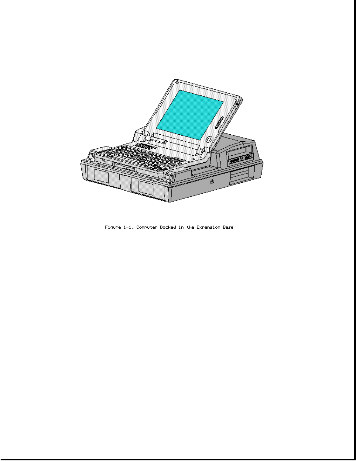
o Compaq SmartStation (Figure 1-1)
o Compaq LTE Lite Desktop Expansion base (with a Compaq LTE Lite Upgrade
Adapter)
o Compaq MiniStation/EN or Compaq MiniStation/TR
When docked in one of these options, the computer has the following
additional features:
o A single connection that provides multiple pass-through connections to
options such as a printer, monitor, and other external equipment
o Built-in network and SCSI-2 capability (on the Compaq SmartStation and
Compaq MiniStations only)
o Two internal drive bays (on the expansion bases only)
o Two full size 8-/16-bit Industry Standard Architecture (ISA) expansion
slots (on the expansion bases only)
Page 6
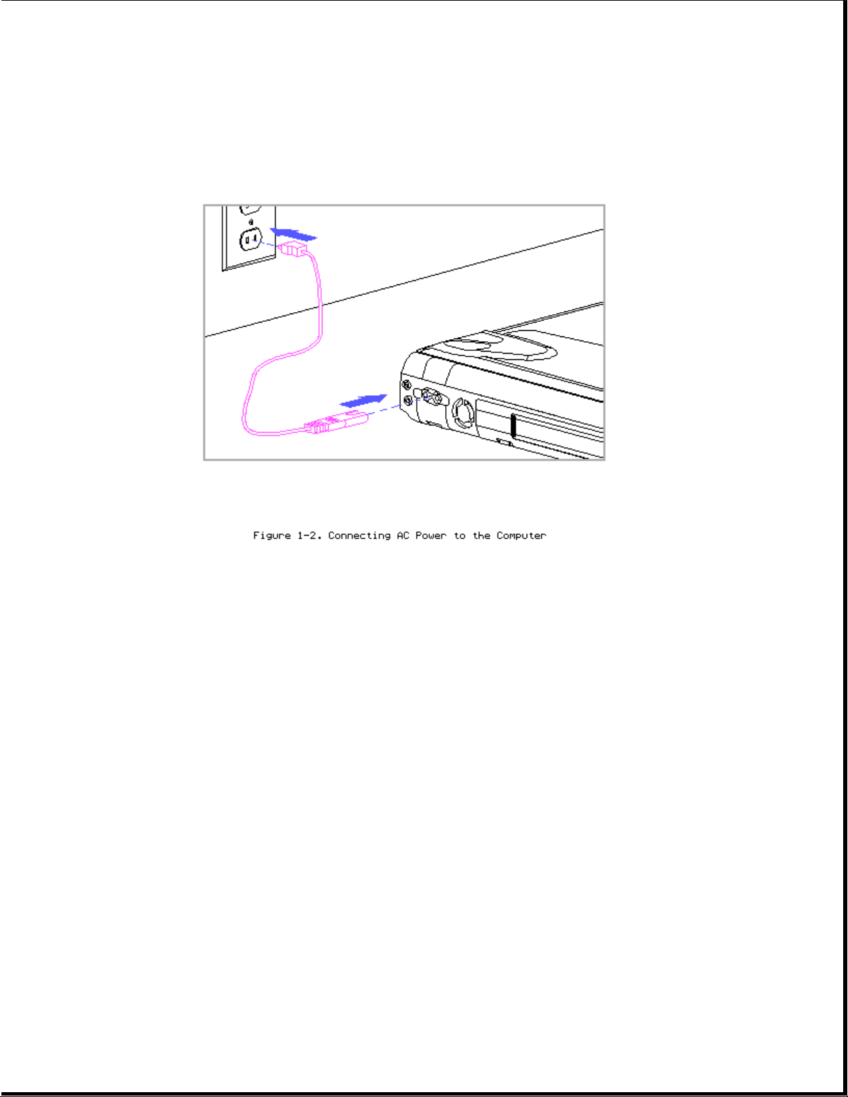
Computer power is supplied through one of the following sources:
o An internal battery pack
o The computer's internal AC adapter when connected to the power cord
(Figure 1-2)
o The computer's internal AC adapter when docked in a convenience base
o The 198-pin external options connector when docked in an expansion base
(provides DC power)
o Automobile Adapter (provides DC power)
Page 7
1.3 Models And Features
Models
Table 1-1 lists the Compaq LTE Elite models and model-specific features.
Table 1-1. Compaq LTE Elite Computer Models
===========================================================================
Model Display Processor Cache RAM Hard Drive
===========================================================================
4/75CX 9.5" Color TFT 486 DX4/75 MHz 16 KB 8 MB 340 or 510 MB
4/50CX 9.5" Color TFT 486 DX2/50 MHz 8 KB 8 MB 340 MB
4/40CX 8.4" Color TFT 486 DX2/40 MHz 8 KB 4 MB 170 or 340 MB
4/50E 9.5" Mono TFT 486 DX2/50 MHz 8 KB 4 MB 250 MB
4/40C 9.5" Color STN 486 DX2/40 MHz 8 KB 4 MB 170 MB
===========================================================================
Features
All models of the computer have the following features:
Internal
Page 8

o Internal AC adapter
o Upgradeable SL Enhanced Intel486 microprocessors
o User upgradeable display with integrated trackball
o Local bus graphics and graphics accelerator with 1024 x 768 external
video support
o Simultaneous display capability
o Removable 2.5-inch hard drive
o Reprogrammable flash ROM (Section 1.9)
o 4 MB system RAM expandable to 20 MBs or 8 MB system RAM expandable to 24
MBs. The following memory expansion boards are available (Section 1.6):
-4MB
-8MB
-16MB
o 1.44 MB/720 kilobyte (and 1.2 MB Japanese standard), 3.5-inch diskette
drive
o Internal dynamic speaker
o Internal 101-/102-key compatible keyboard (Enhanced III type with 12
function keys)
o External keyboard/mouse support
o External numeric keypad support
o Enhanced parallel port (EPP 1.9)
o PCMCIA slot, capable of handling one of the following card combinations:
- Two PCMCIA Type I or Type II cards
- One PCMCIA Type III card
o Nickel metal hydride (NiMH) battery pack
o Battery power management features, including the following:
- Four levels of power management
- Advanced Power Management (APM)
- Standby
- Hibernation
- Screen save
- Hard drive idle
- PCMCIA slot power management
- Battery gauge
- Auxiliary battery (to protect data during battery pack replacement)
o AC power management features including the following:
- Standby
- Hard drive idle
- Screen save
o Saving of changes to hotkey settings when computer is turned off
o Electronic security features
Page 9

o The following preinstalled software:
- MS-DOS and Microsoft Windows
- TabWorks utility (alternative to Program Manager)
- Computer Setup, Computer Checkup, Power Management, and Security
Management utilities
- Automatic PCMCIA configuration utilities for MS-DOS and Windows
- Windows-based online documentation
- Plug and Play BIOS
- MS-DOS- and Windows-based shutdown capability (for closing out
applications and turning off computer)
- Microsoft Video for Windows Runtime Version
- Adaptec 6360 SCSI drivers
- Universal Netware Client for simplified setup of a Netware network
- Intel Ethernet drivers and TI Token Ring drivers for networks other
than Netware
- Western Digital WIN graphics drivers
- Logitech Trackball drivers
1.4 Controls And Leds
This section covers the computer controls and LEDs (Figure 1-3).
Page 10
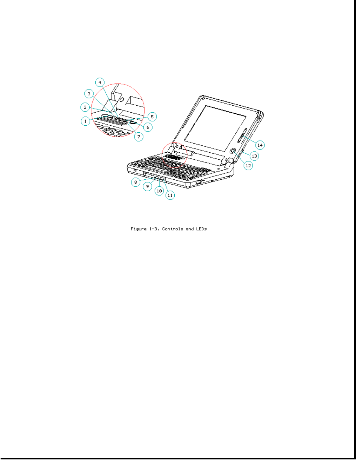
1. Caps lock LED
2. Display switch
3. Scroll lock LED
4. Num lock LED
5. Power switch
6. Standby button
7. Power/standby LED
8. Hard drive LED
9. Diskette drive LED
10. Power/standby LED
11. Battery LED
12. Trackball
13. Trackball buttons
14. Display control slide(s)
LEDs
Table 1-2 lists the function of the LEDs.
Table 1-2. LEDs
===========================================================================
LED Name Status Indication Location Color
===========================================================================
Page 11

Power/ On Power on LED on top of unit Green
standby Flashing Standby (active when display is
open). Identical LED on
front of unit (active
when display is closed).
--------------------------------------------------------------------------Battery On Battery Front of unit Orange
State charging
Flashing LowBatt 1
at one
per
second
Flashing LowBatt 2
at two
per
second
--------------------------------------------------------------------------Hard Drive On Hard drive Front of unit Green
Activity being
accessed
--------------------------------------------------------------------------Diskette On Diskette Front of unit Green
Drive drive being
Activity accessed
--------------------------------------------------------------------------Scroll On Scroll lock Top of unit Green
Lock selected
--------------------------------------------------------------------------Caps Lock On Caps lock Top of unit Green
selected
--------------------------------------------------------------------------Num Lock On Num lock Top of unit Green
selected
===========================================================================
Display Switch
The computer has a display switch mounted on the power interface board
(PIB) located near the display hinge. When the display is closed, this
switch activates the front-mounted power/standby LED and simultaneously
deactivates the display and the top-mounted LEDs.
Trackball
The computer has an integrated PS/2 style trackball located on the display
bezel. The trackball is disabled whenever an external mouse is connected to
the keyboard/mouse connector. The trackball buttons are located on the back
side of the display.
1.5 Connectors
This section covers the I/O pass-through connectors on the computer
(Figure 1-4). Refer to Appendix A for connector pin assignments.
Page 12
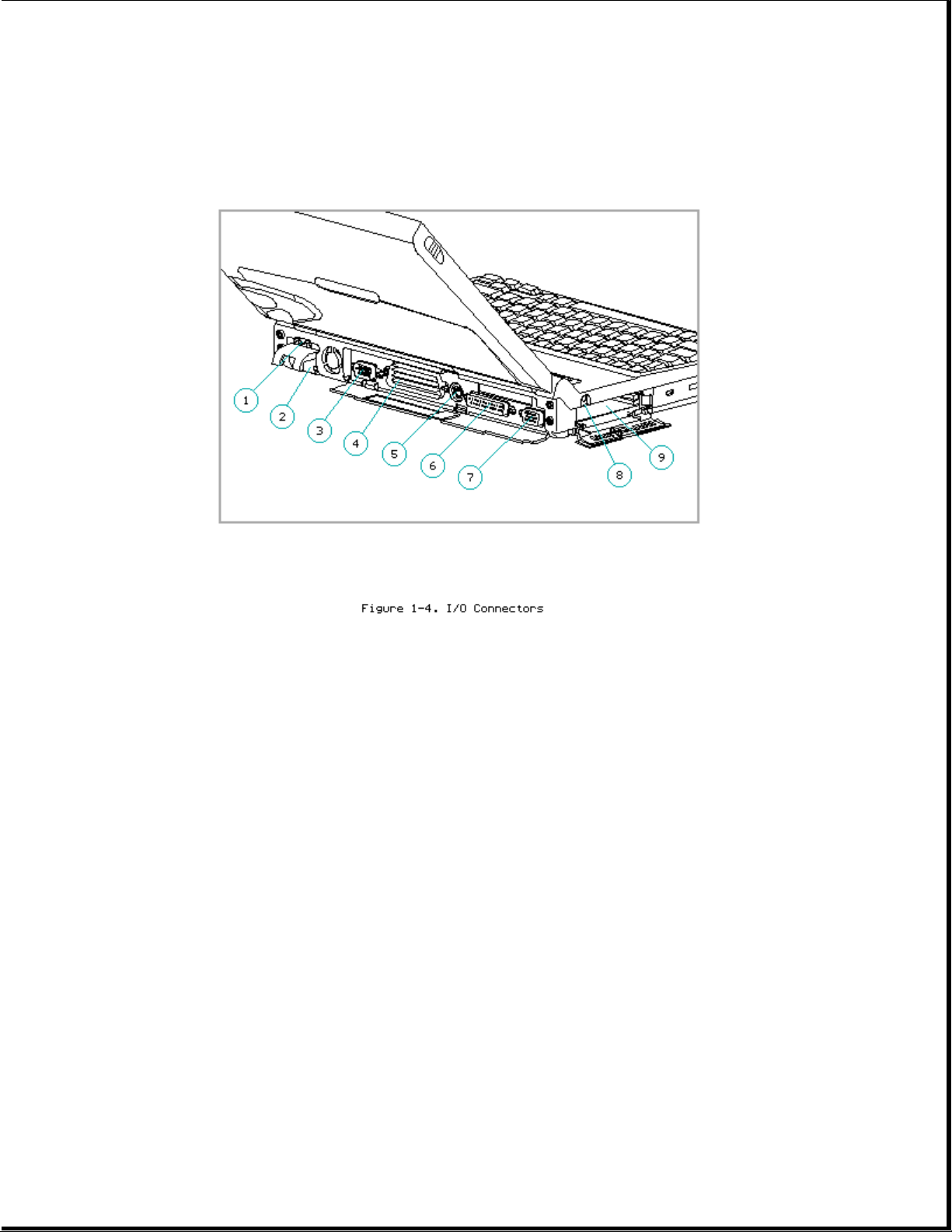
1. AC power
2. Automobile Adapter
3. Serial
4. 198-pin external options
5. Keyboard/mouse
6. Parallel
7. External monitor
8. Numeric keypad
9. PCMCIA
AC Power Connector
When the computer is docked in the convenience base and the convenience
base is turned on, AC power is applied to the computer's AC power
connector. (The 198-pin connector carries all other signals between the two
units.)
Automobile Adapter Connector
The computer has an automobile adapter connector that accepts an 18.5 volt,
1.73 amp DC input from the Automobile Adapter. This connector is covered
by an access door (Figure 1-5).
Page 13
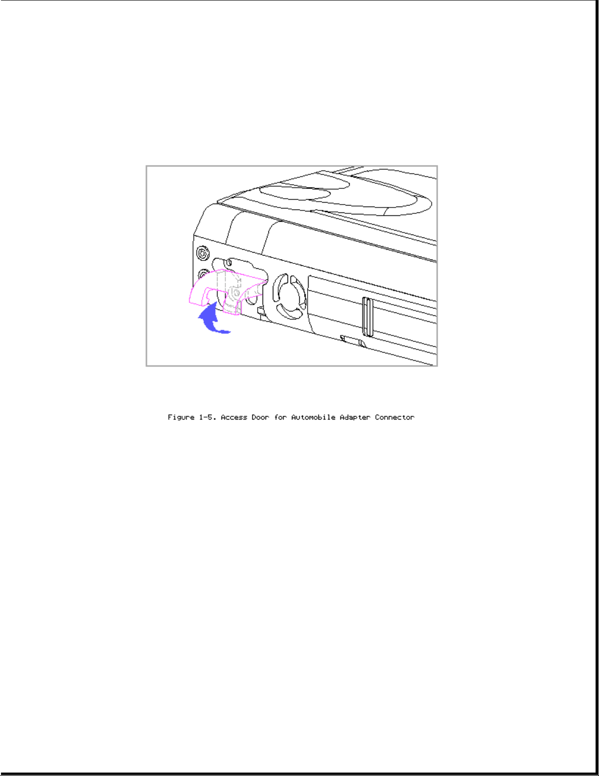
NOTE: The automobile adapter converts 12 volts DC from the automobile to
18.5 volts DC for use by the computer.
>>>>>>>>>>>>>>>>>>>>>>>>>>>>>>>>> CAUTION <<<<<<<<<<<<<<<<<<<<<<<<<<<<<<<<<
The computer has an access door for the automobile adapter connector that
is designed to allow only one type of power input (AC or DC) to be
connected at a time (Figure 1-5). Do not attempt to defeat this protective
feature of the door or internal damage to the computer may result.
>>>>>>>>>>>>>>>>>>>>>>>>>>>>>>>>>>>>><<<<<<<<<<<<<<<<<<<<<<<<<<<<<<<<<<<<<<
Serial Connector
The serial connector supports the serial interface which meets EIA RS232C
specifications.
198-Pin External Options Connector
The 198-pin external options connector handles the signal interface between
the computer and the expansion base or convenience base.
NOTE: When connected to an expansion base, power to the computer is carried
through the 198-pin connector (DC power).
Page 14

Keyboard/Mouse Connector
The keyboard/mouse connector can be connected to a PS/2 mouse or an external
enhanced keyboard. Connecting the mouse/keyboard connector to a mouse
disables the integrated trackball, while connecting the mouse/keyboard
connector to an external keyboard disables the internal keyboard.
Parallel Connector
The parallel connector supports the parallel interface which meets
EPP 1.9 specifications.
External Monitor Connector
The external monitor connector provides an output for an external monitor
with a maximum resolution of 1024 x 768 lines.
NOTE: The computer can simultaneously display on an external monitor and
the integrated display panel.
Numeric Keypad
Connecting the numeric keypad connector to an external numeric keypad
disables the embedded numeric keypad feature.
PCMCIA Connector
The computer has a PCMCIA connector accessible through a PCMCIA slot on the
left side of the computer (refer to "PCMCIA Slot" in Section 1.6). The
PCMCIA connector supports the PCMCIA interface which meets PCMCIA 2.1
specifications.
1.6 Functional Descriptions
This section covers functional descriptions of key parts and features of
the computer. For assembly/disassembly instructions for the parts described
in this section, refer to Chapter 4.
System Board
Page 15
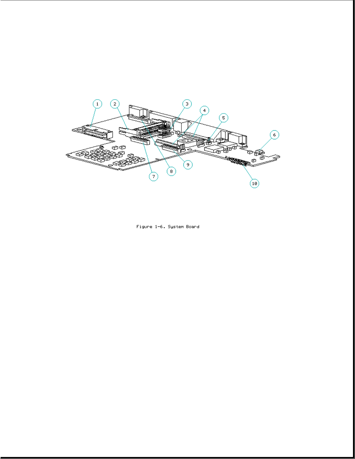
The system board (Figure 1-6) provides the following:
o Connector for removable hard drive [1]
o PCMCIA connector [2] (refer to "PCMCIA Slot")
o Board-to-board connection to the following devices:
- Power interface board (PIB) [3]
- Processor board [4]
- Memory expansion board (on underside of system board)
o Cable connection to the following devices:
- Internal AC power supply board [5]
- Fan [6]
- Internal keyboard [7]
- Display [8]
- Diskette drive [9]
- LED cable assembly for front-mounted LEDs (on underside of system board)
Page 16

o Battery charging circuitry and battery contacts [10] for battery pack
o External input/output (I/O) connectors (Figure 1-4)
o DC-to-DC power supply (refer to "DC-to-DC Power Supply" in this section)
o 256 Kbyte flashable shared system ROM and keyboard ROM
o 4 or 8 MB base RAM (depending on the model)
o System controller, which provides the following:
- Interface to the processor board for memory management (including
memory refresh)
- Two DMA controllers
- Two interrupt controllers
- Clock generator
- Programmable interval timer
- System management interrupt (SMI) support logic
- Power management features
o Peripheral controller, which provides the following:
- Integrated keyboard controller
- Industry Standard Architecture (ISA) support logic
- Circuit for interfacing to the hard drive
- Control of parallel and serial interfaces, including serial interfaces
for a numeric keypad, mouse/keyboard, and internal trackball
o PCMCIA controller
o Local bus video controller
o Diskette drive controller
o Docking sense logic
o Secondary temperature sensor for controlling the fan (refer to
"Temperature Sensors")
DC-to-DC Power Supply
The DC-to-DC power supply is integrated into the system board. It converts
DC voltage input to regulated 3.3 volts, 5 volts, and 12 volts DC. The DC
Page 17
voltage input comes from one of the following sources:
o Internal AC power supply
o Battery pack
o Automobile adapter
o 198-pin external options connector (from expansion base)
o Auxiliary battery
To replace the DC-to-DC power supply, the system board must be replaced.
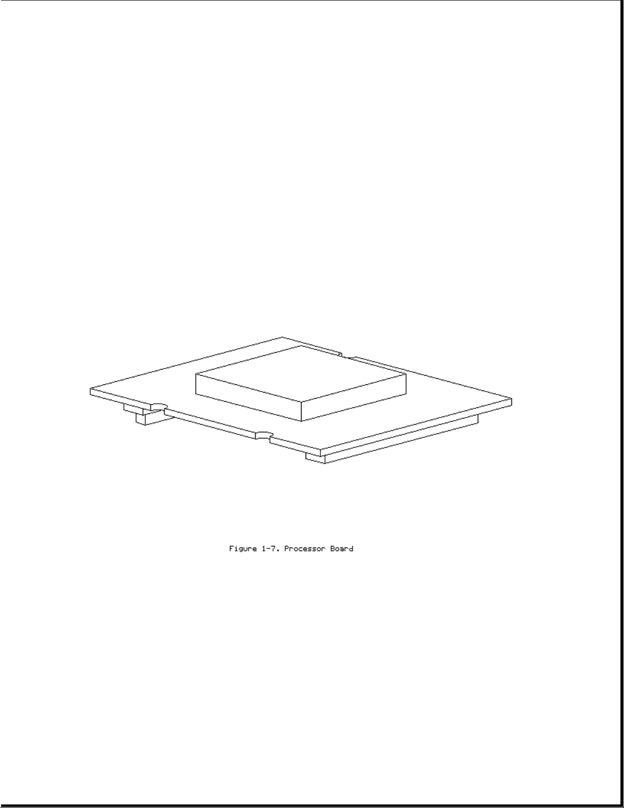
Processor Board
The SL Enhanced Intel486 processor has an integrated coprocessor and is
upgradeable by replacing the processor board (Figure 1-7). The system
automatically adjusts to the new configuration. In addition, the processor
board contains the primary temperature sensor (refer to "Temperature
Sensors").
Some models have a heat sink attached. The computer comes with one of the
following processors:
o 486 DX4/75 MHz
o 486 DX2/50 MHz
o 486 DX2/40 MHz
Page 18

NOTE: The 75 MHz processor is also available as an upgrade option.
Temperature Sensors
The primary temperature sensor is located on the processor board and the
secondary temperature sensor is located on the system board. These sensors
turn the fan on when the system approaches maximum reliable operating
temperatures.
If the temperature continues to rise, a system management interrupt (SMI)
is generated that creates a pop-up window (depicting a thermometer) to warn
the user of the temperature overload and the unit goes into Standby within
several seconds. If the temperature continues to rise, the computer turns
itself off.
NOTE: The temperature sensors are integrated into the processor board and
the system board. To replace a temperature sensor, the appropriate
board must be replaced.
Power Interface Board (PIB)
The power interface board (PIB) (Figure 1-8) is mounted to the system board
by a 16-pin connector. The PIB provides the following features:
Page 19
o Numeric keypad connector
o Speaker and speaker amplifier
o Power switch
o Standby button
o Display switch
o The following LEDs:
- Power/standby
- Scroll lock
- Caps lock
- Num lock
Refer to Section 1.4 for more information on the controls and LEDs listed
above.
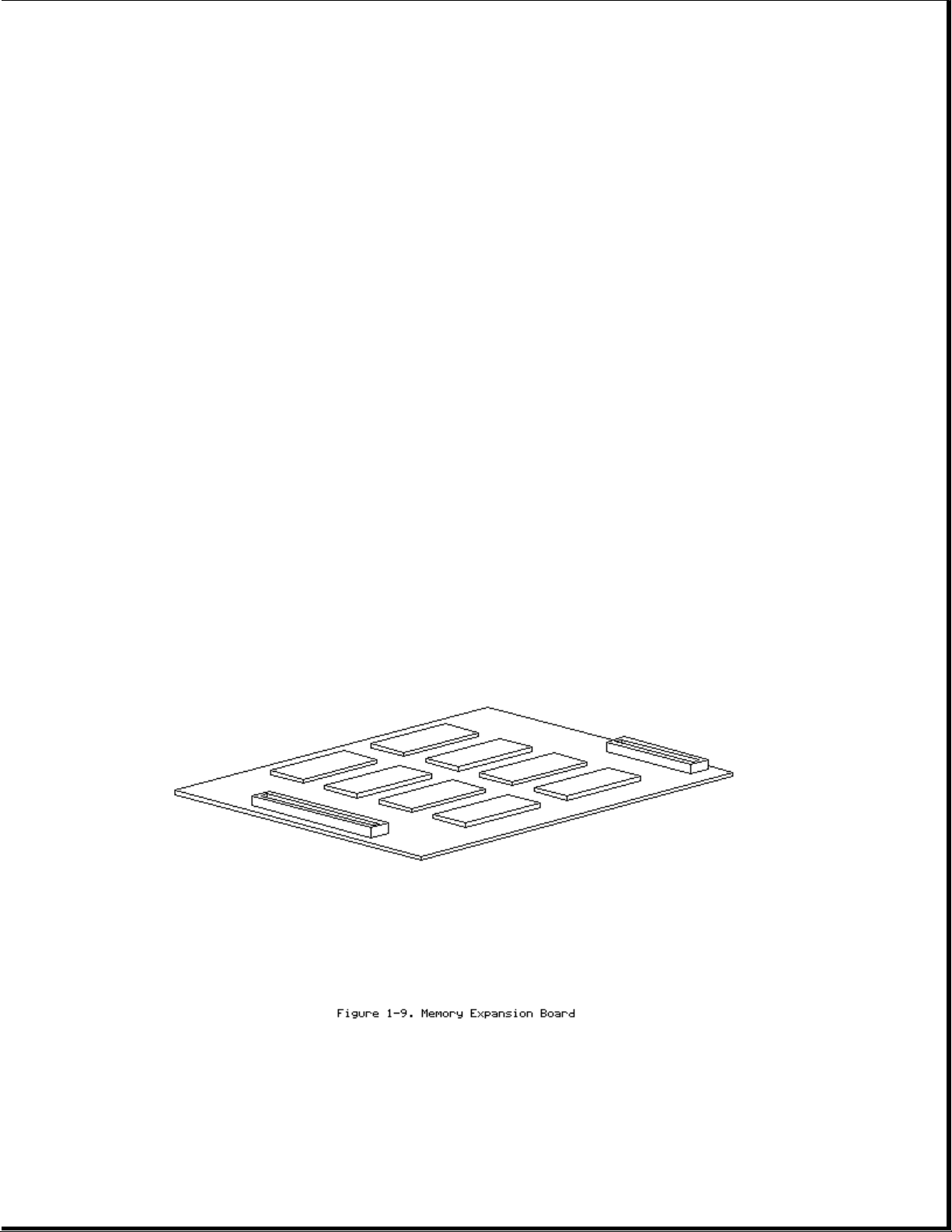
Memory Expansion Board
The 4 or 8 MB base RAM memory (depending on the model) may be increased by
adding an optional memory expansion board (Figure 1-9). The memory
expansion board plugs directly into the back side of the system board
(Section 4.6).
The system supports the following 3.3 volt memory expansion boards (which
operate at 70ns):
Page 20
o4MB
o8MB
o16MB
NOTE: Some early memory expansion boards for the Concerto Family of
Personal Computers (option kit numbers 144790-001 and 144790-002)
operate at 80 ns and do not function properly when installed in the
Compaq LTE Elite Family of Personal Computers, which operate at
70 ns. Use only Compaq LTE Elite memory expansion boards
(Table 3-2).
Refer to the table in Section 5.3 for a list of total RAM memory based on
available system memory and memory obtained from the expansion board.
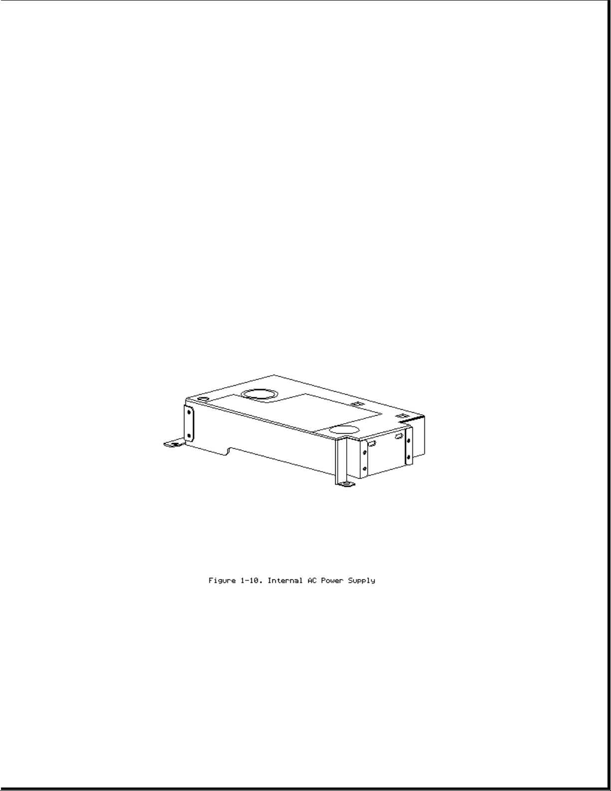
Internal AC Power Supply (AC-to-DC)
The computer is powered by a high-efficiency, board-mounted, internal
AC-to-DC power supply (Figure 1-10). The power supply provides the computer
with an 18.5 volt DC output for running all computer functions, including
charging the internal battery pack.
Fan
Page 21
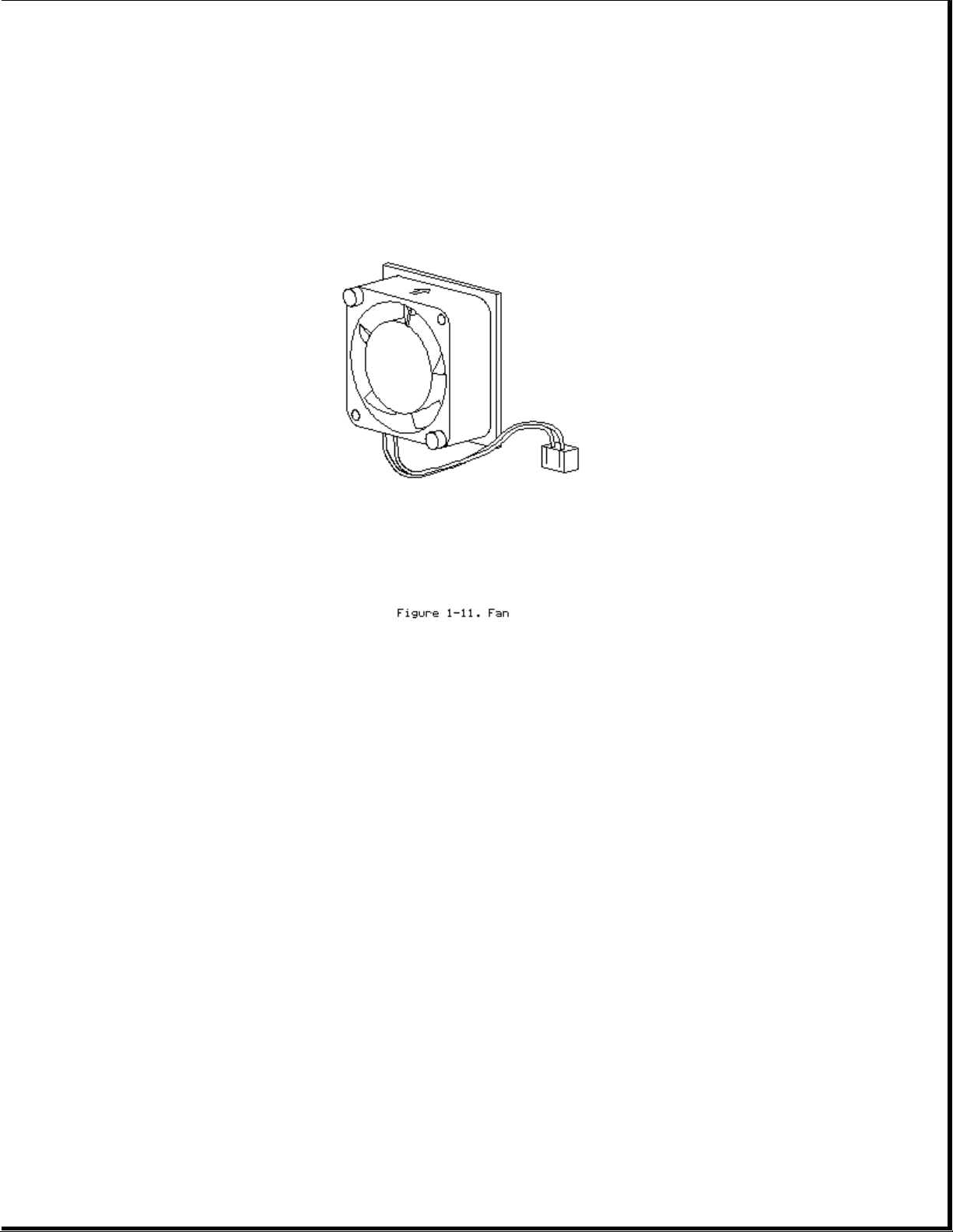
The internal fan (Figure 1-11) draws in fresh air through vent holes in the
PCMCIA compartment door, then exhausts it out the back of the computer.
The fan operates on 5 volts and is controlled by temperature sensors
located near the internal power supply and the processor board. The fan is
designed to turn on automatically when the system approaches maximum
reliable operating temperatures (refer to "Temperature Sensors" in this
section).
The fan is integrated into the input/output (I/O) bracket/fan assembly. To
replace the fan, the I/O bracket/fan assembly must be replaced.
>>>>>>>>>>>>>>>>>>>>>>>>>>>>>>>>> CAUTION <<<<<<<<<<<<<<<<<<<<<<<<<<<<<<<<<
To properly ventilate the computer, allow at least a 3-inch (7.62 cm)
clearance at the back and sides of the unit.
>>>>>>>>>>>>>>>>>>>>>>>>>>>>>>>>>>>>><<<<<<<<<<<<<<<<<<<<<<<<<<<<<<<<<<<<<<
Keyboard
The internal keyboard is connected to the system board by a flex cable. In
addition to the internal keyboard, there is a connector for an external
keyboard/mouse.
Battery Pack
Page 22
The removable internal nickel metal hydride (NiMH) battery pack connects to
the computer through a set of battery contacts mounted on the system board.
Battery charging functions are controlled by the DC-to-DC converter on the
system board. The battery pack contains RAM memory that saves the last
recorded battery operating time and battery fuel gauge values.
Refer to Appendix B for information on increasing battery pack operating
time, ensuring battery gauge accuracy, conditioning the battery pack, and
disposal of a used battery pack.
>>>>>>>>>>>>>>>>>>>>>>>>>>>>>>>>> WARNING <<<<<<<<<<<<<<<<<<<<<<<<<<<<<<<<<
Do not crush, puncture, or incinerate the battery pack or short the battery
pack external contacts. Do not open a battery pack, as this damages the
pack, makes it unusable, and exposes potentially harmful battery
components. There are no field-serviceable parts located inside the battery
pack.
>>>>>>>>>>>>>>>>>>>>>>>>>>>>>>>>>>>>><<<<<<<<<<<<<<<<<<<<<<<<<<<<<<<<<<<<<<
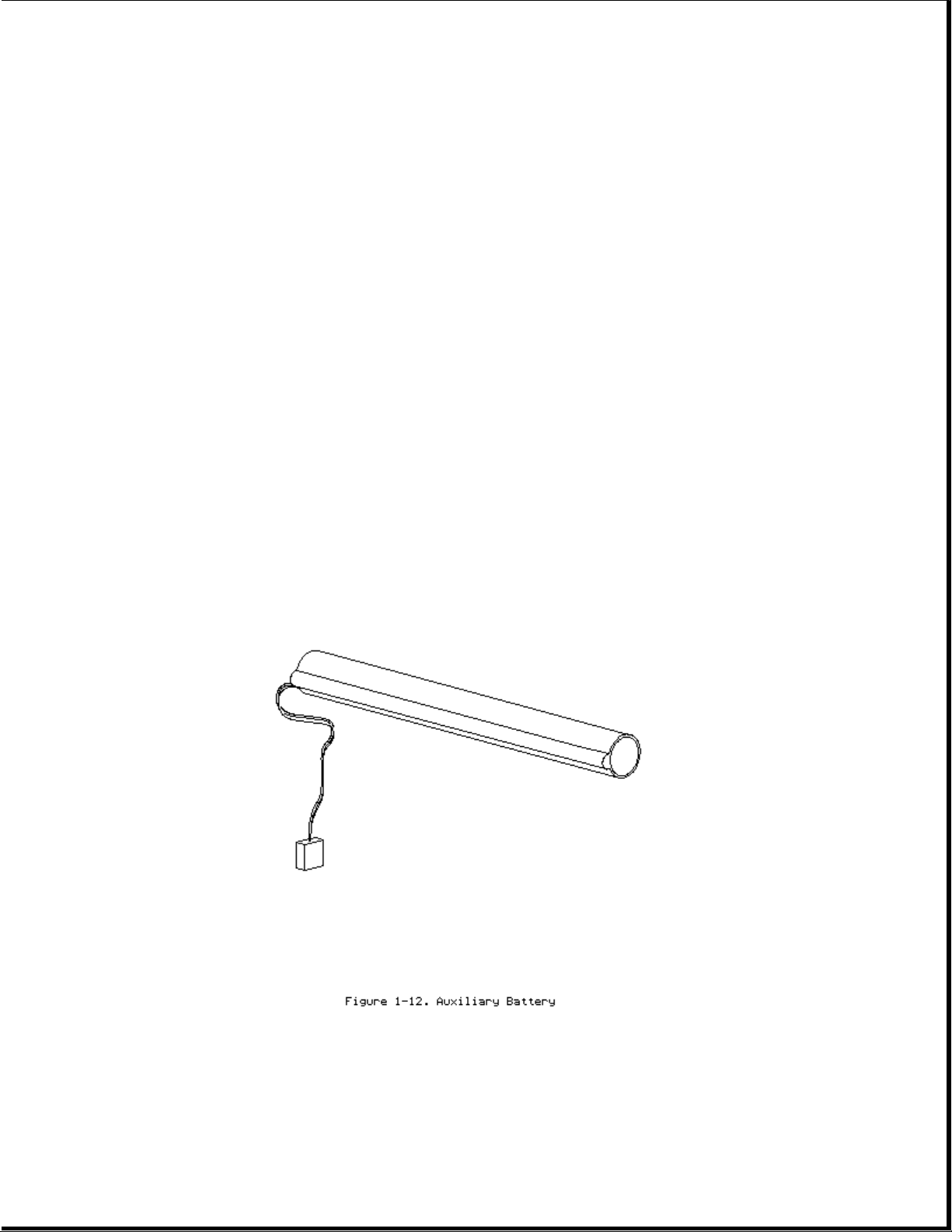
Auxiliary Battery
The internal auxiliary battery (Figure 1-12), mounted on the I/O bracket,
supplies voltage to the system real-time clock and maintains alarm, time,
date, and configuration information when the battery pack and external
power sources are removed. In addition, the auxiliary battery protects RAM
Page 23

memory for a one-minute period during Standby to allow a battery pack to be
replaced.
The auxiliary battery has a nickel cadmium cell that supplies 7.2 volts for
50 mAmp hours. The auxiliary battery recharges when the computer is on
while connected to an external power source or the battery pack. It takes
approximately 10 hours to recharge a fully discharged auxiliary battery
using AC power and approximately 20 hours to recharge it using the battery
pack.
>>>>>>>>>>>>>>>>>>>>>>>>>>>>>>>>> WARNING <<<<<<<<<<<<<<<<<<<<<<<<<<<<<<<<<
Do not crush, puncture, or incinerate the auxiliary battery or short the
auxiliary battery external contacts. Do not open an auxiliary battery, as
this damages the battery, makes it unusable, and exposes potentially
harmful battery components. There are no field-serviceable parts located
inside the battery.
>>>>>>>>>>>>>>>>>>>>>>>>>>>>>>>>>>>>><<<<<<<<<<<<<<<<<<<<<<<<<<<<<<<<<<<<<<
>>>>>>>>>>>>>>>>>>>>>>>>>>>>>>>>> CAUTION <<<<<<<<<<<<<<<<<<<<<<<<<<<<<<<<<
If the computer is unused for approximately 60 days without being connected
to an external power source, a fully charged auxiliary battery will drain
to a critically low level. This may result in loss of alarm, time, and date
information. If this happens, recharge the auxiliary battery or replace it
if it is defective (refer to Section 4.8). Run Computer Setup to restore
the alarm, time, and date information (refer to Section 1.8).
>>>>>>>>>>>>>>>>>>>>>>>>>>>>>>>>>>>>><<<<<<<<<<<<<<<<<<<<<<<<<<<<<<<<<<<<<<
NOTE: CMOS password and configuration information is copied to an EEPROM so
that it is not lost if the auxiliary battery is unplugged or
discharged.
Diskette Drive
The standard 11 mm diskette drive is connected to the system board by a
cable. The drive reads and writes to 3.5-inch 1.44 MB (high density) and
720 kilobyte (double density) diskettes. With the proper software support,
the drive is also capable of reading and writing to 1.2 MB Japanese
standard diskettes.
Hard Drive
Page 24
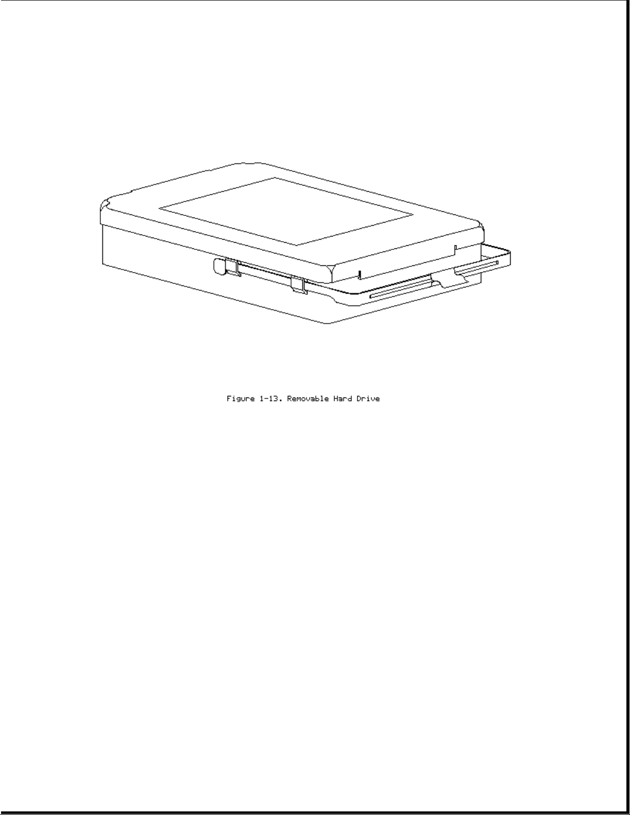
The 2.5-inch hard drive (Figure 1-13) is user-removable from the front of
the computer (Section 4.12). The hard drive release button allows the drive
to be removed without disassembling the computer. A connector on the hard
drive enclosure mates to a connector on the system board.
NOTE: The hard drive may have either a metal handle (Figure 1-13) or a
plastic pull tab that is attached directly to the hard drive
enclosure.
Hard drive security clips can be installed to prevent the hard drive from
being removed (refer to Section 4.12). When the security clips are
installed, a lock label should be attached to the front of the hard drive
to indicate that the drive is locked in place. The computer must be
partially disassembled to remove the security clips before the hard drive
can be removed.
NOTE: The Compaq Diagnostics utilities (which include Computer Setup)
reside in a hidden partition on the Compaq LTE Elite hard drive (not
in the ROM). There is no preinstalled software on a new spare hard
drive. When installing a new spare hard drive, the hidden partition
must be created, the diagnostics utilities must be installed, and the
C: partition must be formatted before restoring any data
(Section 4.12). On the option kit hard drives, the hidden partition
Page 25
is already created and the diagnostics utilities are already
installed.
IMPORTANT: The hard drive must be handled with care. Refer to the cautions
listed in Section 4.12.
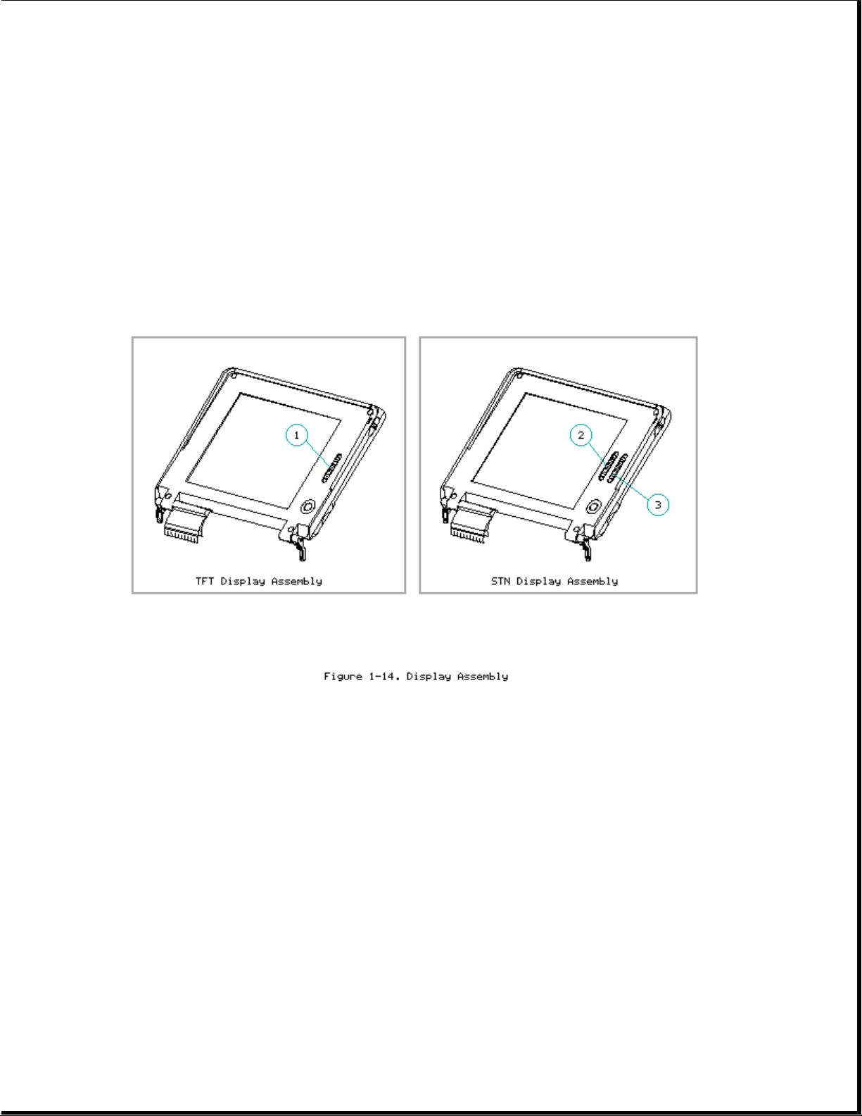
Display Assembly
The display assembly (Figure 1-14) is connected to the system unit by
clutches, a display cable and a ground cable. The display assembly includes
an integrated trackball board and an inverter board. The color and
black-and-white TFT display assemblies have an externally adjustable
brightness control slide [1]. The color STN display assembly has two
externally adjustable control slides: one for contrast [2] and one for
brightness [3]. The display assembly comes with one of the following
panels, depending on the model:
o 9.5-inch color STN
o 9.5-inch mono TFT
o 8.4-inch color TFT
o 9.5-inch color TFT
IMPORTANT: In order to optimize display quality and ensure regulatory
compliance, many of the parts in the 9.5-inch color TFT display
can be replaced only by replacing the entire display assembly (Section 4.9).
Page 26
Refer to Section 5.4 for display specifications.
NOTE: A certain number of pixels in the display panel are allowed to be
nonfunctional due to limitations in LCD technology.
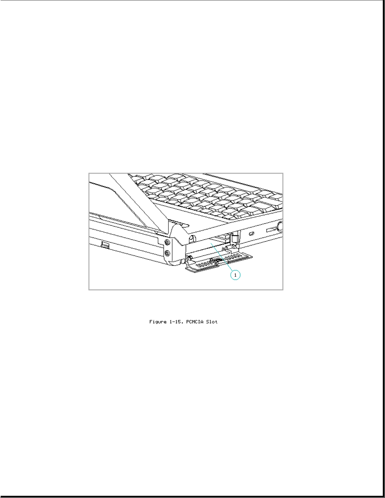
PCMCIA Slot
The PCMCIA connector is mounted to the system board. The connector is
accessible through the PCMCIA slot [1], (Figure 1-15), which is covered by
a PCMCIA compartment door. The slot accommodates one of the following card
combinations:
o Two PCMCIA Type I or Type II cards
o One PCMCIA Type III card
The PCMCIA slot supports both 5 volt and 3.3 volt PCMCIA cards in
accordance with PC Card Standard Release 2.1 or later and the Exchangeable
Card Architecture (ExCA) Specification 1.10.
Page 27
NOTE: PCMCIA stands for Personal Computer Memory Card International
Association. PCMCIA standards continue to change. Many cards on the
market do not comply with the PCMCIA specifications and, therefore,
do not function properly in the computer. To assist users in
selecting compatible PCMCIA devices, Compaq provides a list of
third-party cards that have been tested in Compaq products. To ensure
compatibility, select a Compaq PCMCIA modem or other vendor cards on
the tested list. Call Compaq Reseller Support to have a copy of the
list faxed to you.
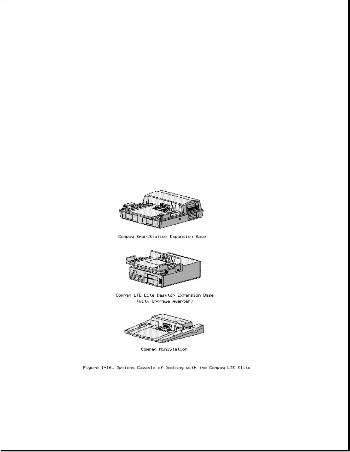
1.7 Docking Options
The Compaq LTE Elite docks with the following options (Figure 1-16):
o Compaq SmartStation expansion base
o Compaq LTE Lite Desktop Expansion Base (with an Upgrade Adapter)
o Compaq MiniStation/EN and MiniStation/TR convenience bases
Refer to Appendix D for more information on docking and undocking.
1.8 Running Computer Setup
The Computer Setup utility resides in a hidden partition on the hard drive.
Page 28

Run Computer Setup for the following situations:
o To configure options
o To update alarm, time, date, or password information
NOTE: Alarm, time, and date information can be lost if the computer is
unused for approximately 60 days without charging the internal
battery pack or without AC power being connected (refer to "Auxiliary
Battery" in Section 1.6). If this information is lost, run Computer
Setup to restore it.
IMPORTANT: Use AC power during Computer Setup procedures. A low battery
condition could initiate Standby and interrupt the program.
To run Computer Setup, complete the following steps:
1. Turn on or restart the computer.
2. Press the F10 key as soon as the cursor moves to the upper-right corner
of the screen.
3. When prompted, select the desired language.
4. Select Computer Setup from the Configuration and Diagnostics menu.
5. Follow the instructions on the screen.
1.9 Reprogrammable Flash ROM
The flash ROM can be reprogrammed to update system firmware and provide the
most recent level of system functionality. In some cases, problems may be
solved by upgrading the ROM.
Erase and reprogram the nonvolatile read only memory (ROM) by using the
ROMPaq utility. The ROMPaq utility is available on the Portables ROMPaq
Upgrade Diskette, which includes on-screen instructions for implementing
the flash ROM upgrade (Table 3-16).
1.10 Power Management
The following power management features are available for conserving AC
power and extending battery operating time:
o Advanced Power Management (APM)
o Power management settings
o Standby
o Hibernation
Advanced Power Management (APM)
APM is installed on the computer and requires no action from the user to
reduce power consumption. APM turns off the processor between keystrokes
Page 29

and when the system is idle. This function is transparent to the user. APM
also provides occasional screen messages about the battery while in the
Windows environment (for example, low power condition).
Power Management Settings
You can select power conservation settings through Computer Setup, Power
Management, or by pressing the Fn + F7 hotkeys to maximize power for
specific requirements. These settings control the power conservation rate
and the timeout values for various system components. A timeout is
specified period of system or component inactivity. After this period, the
system or component (for example, the hard drive) is shut down to conserve
power until it is accessed again.
If the power conservation rate and timeouts are not selected, the computer
uses the default settings listed in Table 1-3.
Table 1-3. Power Conservation Default Settings
===========================================================================
Battery Power AC Power
Feature Default Setting Default Setting
===========================================================================
Standby timeout 5 minutes 15 minutes
Hard drive timeout 2 minutes 15 minutes
Screen save timeout 3 minutes 15 minutes
Display brightness 75% of rated brightness 100% of rated brightness
Processor speed (MHZ) 100% of rated speed 100% of rated speed
===========================================================================
Standby
Page 30

Standby is a power conservation mode for battery or AC power operation
during which most of the components (e.g, hard drive, processor, display)
shut down.
The computer initiates Standby under the following conditions:
o When the user presses the standby button [1] (Figure 1-17).
o After a timeout occurs.
o When the battery pack voltage reaches a low level (if this option is
preselected).
When the user exits Standby (by pressing the standby button again),
information returns to the screen at the point where Standby was initiated.
Under battery power, the computer can maintain Standby for up to 120 hours.
NOTE: The computer cannot initiate Standby under the conditions listed
above when docked in an expansion base or a convenience base. In
addition, the computer cannot initiate Standby if there is activity
from the hard drive, diskette drive, mouse, keyboard, PCMCIA slot,
parallel connector, or serial connector.
Page 31

Hibernation
Hibernation is a power conservation mode that performs the following
functions:
o Locks the keyboard and clears the screen.
o Saves all current information in memory and the place in the application
to the hard drive.
o Turns the computer off.
Hibernation is preenabled on the computer and the Hibernation file is
preinstalled on the hard drive. The Hibernation file is slightly larger
than the total RAM memory of the computer (system memory and memory
expansion board).
Hibernation is initiated by one of the following means:
o Automatically according to the preselected system timeout.
o Automatically when the battery reaches a low battery level if
preselected.
o Manually by simultaneously pressing the Fn key and standby button.
When the computer is turned on again, the system exits Hibernation and the
user is returned to the previous place in the application from the hard
drive.
NOTE: Hibernation cannot be initiated when the computer is in an expansion
base or a convenience base.
Battery Operating Time
Battery operating time is affected by variables such as the following:
o Power conservation settings
o Hardware configuration
o Software applications
o Installed options
o Display brightness
o Hard drive usage
o Changes in operating temperature
o Type and number of installed PCMCIA cards
Refer to Appendix B for information on increasing battery pack operating
time, ensuring battery gauge accuracy, conditioning the battery pack, and
disposal of a used battery pack.
Page 32
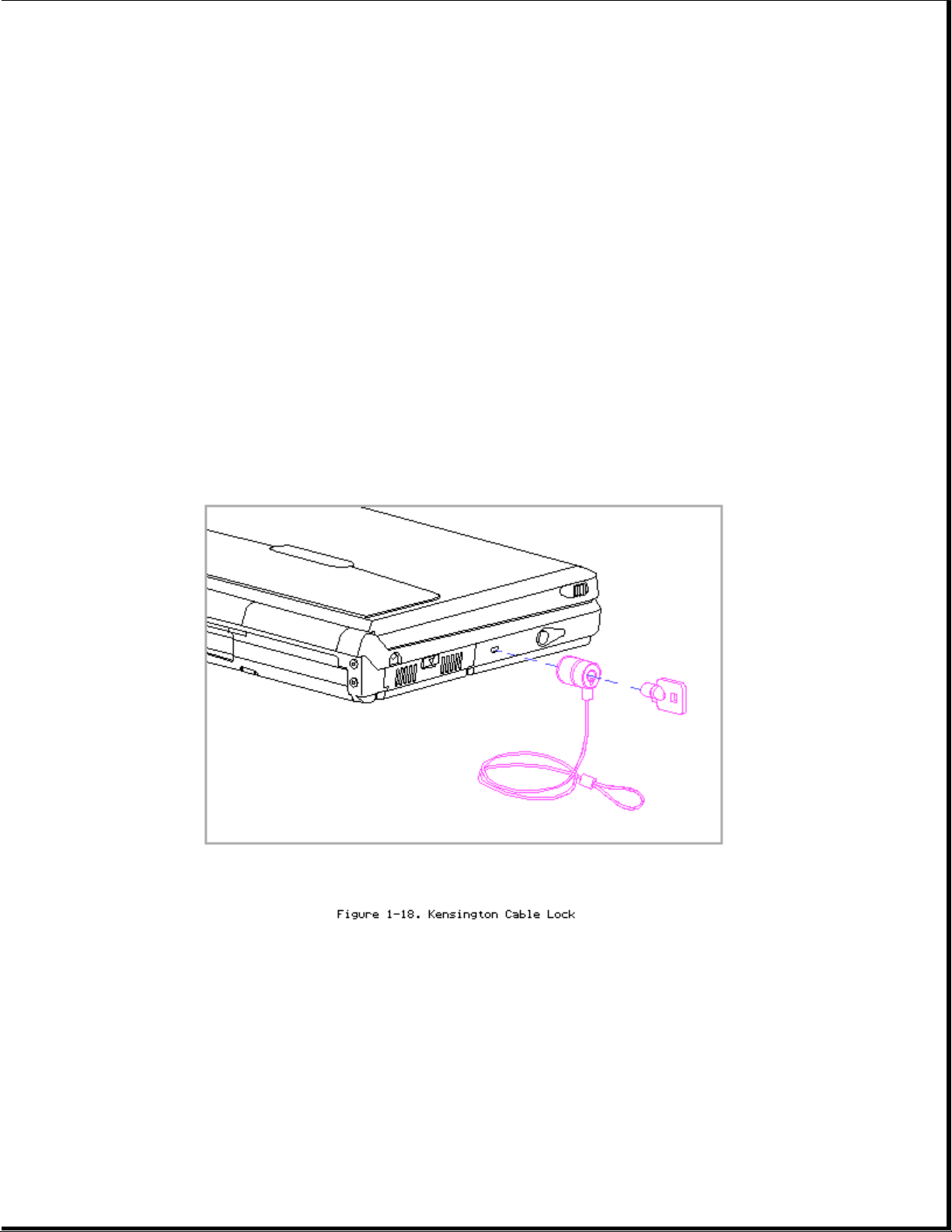
1.11 Security
The computer has the following security features:
o Power-on password and setup password.
o The ability to disable certain components, such as the keyboard, diskette
drive, display, PCMCIA slot, parallel connector, and serial connector, to
prevent unauthorized access.
o Provision for an optional cable lock (Figure 1-18) to lock the computer
to an immovable object.
NOTE: For procedures to clear the power-on password, refer to "Clearing the
Power-On Password" in Section 2.1.
NOTE: The cable lock, Kensington MicroSaver Security System Model 64068
(Figure 1-19), is available from Kensington Microwave Limited or
major computer resellers worldwide at 1-(415)-572-2700. The cable
lock is not available through Compaq.
Page 33

Chapter 2 - Compaq LTE Elite Troubleshooting
Introduction
This chapter covers troubleshooting information for the computer. The basic
steps in troubleshooting include:
1. Following the preliminary steps listed in Section 2.1.
2. Running the Power-On Self-Test (POST) as described in Section 2.2.
3. Running Computer Checkup (TEST) as described in Section 2.3.
4. Following the recommended actions described in the diagnostic tables in
Section 2.4 if you are unable to run POST or Computer Checkup or if the
problem persists after they are run.
When following the recommended actions in Section 2.2, 2.3, and 2.4, carry
them out in the order given. Rerun POST and Computer Checkup after each
recommended action until the problem is solved and no error message occurs.
(Once the problem is solved, do not complete the remaining recommended
actions.)
NOTE: If the problem was intermittent, check the unit several times to
verify that the problem is solved.
Refer to Chapter 4 for any removal and replacement procedures that are
recommended.
2.1 Preliminary Steps
IMPORANT: Use AC power when running POST, Computer Setup, and Computer
Checkup. A low battery condition could initiate Standby and
interrupt the program.
Before running POST and Computer Checkup, complete the following
preliminary steps:
1. If a power-on password has been established, type the password and press
the Enter key.
NOTE: The key symbol (o--m) appears on the screen when the computer is
turned on to indicate that a power-on password is established. If
the password is unknown, it must be cleared (refer to "Clearing
the Power-On Password").
2. Run Computer Setup (Section 1.8).
3. Position the brightness and contrast control slides approximately in the
center of their range and leave the display open.
4. Turn off the computer and external devices.
Page 34

5. Disconnect any external devices that you do not want to test. (Do not
disconnect the printer if you want to test it or use it to log error
messages.)
NOTE: If a problem only occurs when an external device is connected to
the computer, the problem may be with the external device or its
cable. Verify this by running POST with and without the external
device connected.
6. Install loopback plugs in the serial and parallel connectors if you
would like to test these ports (Table 3-13).
7. Ensure that the removable hard drive is installed in the computer.
8. Ensure that the battery pack is inserted in the computer and the
computer is connected to an external AC power source.
When the preliminary steps are complete, you are ready to run POST
(Section 2.2) and Computer Checkup (Section 2.3).
Clearing the Power-on Password
Clearing the power-on password clears CMOS, the EEPROM that contains
configuration information for all external devices, the setup password, and
all other security features including:
o QuickLock
o QuickBlank
o Diskette drive disable
o Diskette boot ability disable
o Serial port disable
o Parallel port disable
o PCMCIA slot disable
NOTE: Disconnecting the auxiliary battery does not clear the power-on
password.
If the password is unknown, clear it by completing the following steps:
1. Turn off the computer.
2. Disconnect the power cord.
3. Remove the battery pack (Section 4.5).
4. Remove the keyboard cover (Section 4.7).
5. Remove the keyboard, but don't disconnect the cable (Section 4.10).
Place the keyboard toward the front of the system unit to access the
jumper located near the lower-right corner of the processor board.
NOTE: The pins used by the jumper are labeled on the system board as
"1," "2," and "3." (Pin "1" is toward the rear of the computer.)
The jumper can be placed simultaneously on pins 1 and 2 (the
"1-2" or "normal" position [1]) or on pins 2 and 3 (the "2-3" or
Page 35

password-clearing position [2]). Refer to Figure 2-1.
6. Move the jumper from the normal "1-2" position [1] to the "2-3"
position [2] (Figure 2-1).
7. Insert the battery pack.
IMPORTANT: Ensure that the battery pack is charged since a low battery
condition could initiate Standby and interrupt the
procedure.
8. Turn on the computer.
The ROM clears the power-on password during POST.
9. After POST finishes, turn off the computer.
10. Remove the battery pack.
11. Move the jumper back to the normal "1-2" position.
Page 36

12. Insert the battery pack.
13. Turn on the computer to verify that the power-on password has been
cleared. If it has not been cleared, remove the battery pack and then
repeat steps 6 through 13. If the password is still not cleared,
replace the system board (Section 4.17).
14. Replace the keyboard.
15. Replace the keyboard cover.
16. Reconnect the power cord to the external outlet.
17. Run Computer Setup (Section 1.8) to reconfigure the system and reset
the power-on and setup passwords.
2.2 Power-On Self-Test (POST)
The Power-On Self-Test (POST) is a series of diagnostic tests that run
automatically when the system is turned on. POST detects which types of
mass storage devices are installed in the computer and checks that the
following assemblies are functioning properly:
o Diskette drive
o Display
o External keyboard
o Hard drive
o Internal keyboard controller
o Memory expansion board
o Processor board
o Speaker on the power interface board (PIB)
o System board
o System memory
o Trackball assembly (POST identifies the trackball but does not actually
test it.)
o Video controller circuitry
Running POST
To run POST, complete the following steps:
1. Turn off the computer.
2. Turn on the computer.
Page 37

If POST does not detect any errors, the computer beeps once or twice to
indicate that POST has run successfully and starts (boots) from the hard
drive (or from a bootable diskette if one is installed in the diskette
drive).
If POST detects errors, the errors are indicated by screen and/or audible
messages. Refer to "Power-On Self-Test (POST) Error Messages" in this
section for a list of POST error messages, probable causes, and recommended
actions.
Run Computer Checkup after POST runs successfully (Section 2.3).
NOTE: If the system is not functioning well enough to run POST, or if the
display is not functioning well enough to show POST error messages,
refer to the troubleshooting tables in Section 2.4.
Power-On Self-Test (POST) Error Messages
Table 2-1 lists visual error messages for POST, audible (beep) error
messages, probable causes, and recommended actions.
Table 2-1. Power-On Self-Test Messages
===========================================================================
Message Beeps Probable Cause Recommended Action
===========================================================================
101 - ROM Error 1 Long, System ROM checksum 1. Inspect the ROM
1 Short invalid. placement.
2. Replace the ROM.
3. Flash the ROM.
4. Replace the system
board.
--------------------------------------------------------------------------101 - I/0 ROM None Option ROM checksum 1. Inspect the ROM
Error invalid. placement.
2. Verify the correct
ROM.
3. Replace the ROM.
--------------------------------------------------------------------------102 - System None Defective DMA, 1. Replace the system
Board Failure timers, etc. board.
2. Replace the processor
board.
--------------------------------------------------------------------------162 - System 2 Short No diskette drive 1. Run Computer Setup.
Options or mismatch in 2. Check diskette cable.
Error drive type. 3. Check diskette drive.
--------------------------------------------------------------------------162 - System 2 Short Configuration Run Computer Setup.
Options Not Set incorrect.
--------------------------------------------------------------------------163 - Time & 2 Short Invalid time or Run Computer Setup.
Date Not Set date in
configuration
memory.
--------------------------------------------------------------------------164 - Memory 2 Short Configuration The following steps
Page 38

Increase memory incorrect. apply to both 164 error
Detected codes:
1. Autosetup will
correct.
2. Verify that memory
board is installed
correctly.
3. Replace memory
board.
4. Replace system board.
-----------------------------------------------164 - Memory 2 Short Configuration
Decrease memory incorrect.
Detected
--------------------------------------------------------------------------168 - CMOS None Auxiliary battery 1. Recharge auxiliary
Checksum charge is low. battery. (Refer to
Invalid "Auxiliary Battery"
in Section 1.6). Run
Computer Setup if
configuration
settings are other
than default. **
--------------------------------------------------------------------------** Autosetup configures to the default settings if you do not run Computer
Setup.
===========================================================================
Message Beeps Probable Cause Recommended Action
===========================================================================
201 - Memory None RAM failure. 1. Make sure the memory
Error module is installed
correctly.
2. Clean the contacts of
the memory module and
system board.
3. Make sure PCMCIA
memory card is
installed correctly
by running PCMCIA
card service
software and
Computer Setup.
4. If using ISA
expansion memory
module, make sure
module is installed
correctly.
5. Replace the memory
module(s) (if
applicable).
6. Replace PCMCIA memory
card.
7. Replace ISA memory
board.
8. Replace system board.
--------------------------------------------------------------------------203 - Memory None RAM failure. Refer to recommended
Address Error actions for Error Code
201.
Page 39

--------------------------------------------------------------------------205 - Memory None Cache memory error. 1. Run Computer Checkup.
Error 2. Replace the processor
board.
--------------------------------------------------------------------------207 - Invalid None Memory module Verify placement of
Memory installed memory.
Configuration incorrectly.
Module
--------------------------------------------------------------------------209 - NCA RAM None RAM Failure. Run Computer Checkup.
Error
--------------------------------------------------------------------------211 - Memory None RAM Failure. Run Computer Checkup.
Failure
--------------------------------------------------------------------------301 - Keyboard None Keyboard failure. The following steps
Error apply to both 301 error
codes:
301 - Keyboard None Keyboard failure.
Error or Text 1. Reseat external
Fixture keyboard cable and
Installed free any stuck keys.
2. Replace keyboard.
3. Replace system board.
===========================================================================
Message Beeps Probable Cause Recommended Action
===========================================================================
303 - Keyboard None System board Replace the system
Controller Error keyboard board.
controller
failure.
--------------------------------------------------------------------------304 - Keyboard None Defective keyboard. Check external keyboard.
or System Unit
Error ----------------------------------------------
Defective system Replace system board.
board.
--------------------------------------------------------------------------40X - Parallel 2 Short Both external Run Computer Setup.
Port X Address and internal ports
Assignment are assigned to
Conflict parallel port X.
--------------------------------------------------------------------------401 - Printer None Defective printer Replace the system
Error controller. board, if applicable.
--------------------------------------------------------------------------501 - Display 1 Long, Video display 1. Replace the video
Adapter Failure 2 Short controller. board if external one
used.
2. Replace the system
board.
--------------------------------------------------------------------------601 - Diskette None Diskette controller 1. Make sure diskette
Controller Error circuitry. drive cable is
seated.
2. Replace the diskette
drive cable.
3. Replace the diskette
drive.
Page 40

4. Replace the system
board.
--------------------------------------------------------------------------602 - Diskette None Diskette in drive A 1. Replace the diskette.
Boot not bootable. 2. Replace the diskette
drive.
3. Replace the system
board.
--------------------------------------------------------------------------605 - Diskette 2 Short Mismatch in drive Run Computer Setup.
Drive Error type.
--------------------------------------------------------------------------610 - External None Switch 3 on the Verify switch 3 setting
storage device vertical circuit and change if necessary.
failure. board is set for
an external drive
but no tape or
diskette drive is
installed in the
expansion base.
---------------------------------------------External storage 1. Turn on external
device not powered storage device and
up. reboot computer.
2. Check and/or replace
power and signal
cables for external
storage device.
===========================================================================
Message Beeps Probable Cause Recommended Action
===========================================================================
611 - Primary 2 Short Configuration Run Computer Setup.
Floppy Port error.
Address
Assignment
Conflict
--------------------------------------------------------------------------612 - Secondary 2 Short Configuration Run Computer Setup.
Floppy Port error.
Address
Assignment
Conflict
--------------------------------------------------------------------------702 - None Coprocessor error. Replace the processor
Coprocessor board.
Detection Error
--------------------------------------------------------------------------702A - 2 Short Coprocessor error. Replace the processor
Coprocessor board.
Detection Error
--------------------------------------------------------------------------703 - CMOS 2 Short Coprocessor or 1. Run the Configuration
Reports A configuration utility.
Coprocessor That error. 2. Replace the processor
Has Not Been board.
Detected by
POST
--------------------------------------------------------------------------1125 - Internal 2 Short Defective internal 1. Run Computer Setup
Serial Port serial port. and check it.
Page 41

Failure 2. Replace the system
board.
--------------------------------------------------------------------------1150 - COM Port Two ports are Run Computer Setup.
Configuration configured in the
Error same address.
--------------------------------------------------------------------------1151 - COM Port 2 Short Both external and Run Computer Setup.
1 Address internal serial
Assignment ports are assigned
Conflict to COM1.
--------------------------------------------------------------------------1152 - COM Port 2 Short Both external and Run Computer Setup.
2 Address internal serial
Assignment ports are assigned
Conflict to COM2.
--------------------------------------------------------------------------1771 - Primary 2 Short Internal and 1. Run Computer Setup.
Disk Port external hard drive 2. Check expansion base
Address controllers are switch settings.
Assignment both assigned to 3. Check unit out of
Conflict the primary expansion base.
address.
===========================================================================
Message Beeps Probable Cause Recommended Action
===========================================================================
1772 - Secondary 2 Short Internal Run Computer Setup.
Disk Port and external hard
Address drive controllers
Assignment are both assigned
Conflict to the secondary
address.
--------------------------------------------------------------------------1780 - Disk 0 None Hard drive/format 1. Run Computer Checkup.
Failure error. 2. Replace the drive.
--------------------------------------------------------------------------1781 - Disk 1 None Hard drive/format 1. Run Computer Checkup.
Failure error. 2. Replace the drive.
--------------------------------------------------------------------------1782 - Disk None Hard drive 1. Run Computer Checkup.
Controller circuitry error. 2. Replace the drive.
--------------------------------------------------------------------------1790 - Disk 0 None Hard drive error or 1. Run Computer Setup
Failure wrong drive type. and Computer Checkup.
2. Replace the drive.
--------------------------------------------------------------------------1791 - Disk 1 None Hard drive error or 1. Run Computer Setup
Failure wrong drive type. and Computer Checkup.
2. Replace the drive.
--------------------------------------------------------------------------1792 - Secondary None Incorrect C/D Verify position of
Disk Controller switch settings. C/D and configuration
Failure switches in expansion
base and run Computer
Setup.
----------------------------------------------
Defective hard 1. Reseat hard drive
drive or hard drive cable and replace
cable. if required.
2. Install a different drive.
Page 42

----------------------------------------------
Defective system If the drive in the
board in expansion expansion base is
base. designated as secondary,
replace the system
board in the expansion
base.
----------------------------------------------
Defective system If the drive in the
board in computer. computer is designated
as secondary, replace
the system board in the
computer.
--------------------------------------------------------------------------1793 - Secondary None Refer to probable Refer to recommended
Disk Controller causes for Error actions for Error Code
or Disk Failure Code 1792. 1792.
--------------------------------------------------------------------------Audible 1 Short Power-on None.
successful.
--------------------------------------------------------------------------Audible 2 Short Power-on None.
successful.
--------------------------------------------------------------------------(RESUME = F1 None As indicated to Press the F1 key.
KEY) continue.
===========================================================================
2.3 Computer Checkup (Test)
After POST runs successfully, run the latest version of Computer Checkup
(TEST). Computer Checkup determines if the computer assemblies and options
are recognized by the system and functioning properly. Run Computer Checkup
after installing or connecting a new assembly or option.
Computer Checkup is installed on the hard drive. If the hard drive is not
functioning, you can run it from the Compaq Diagnostics diskette by
inserting the diskette in Drive A before turning on the computer.
NOTE: It is recommended that you make a diskette copy of Compaq Diagnostics
and keep it available for future need. If necessary, a copy can be
obtained from the Compaq Customer Support Center.
Running Computer Checkup
To run Computer Checkup from the hard drive, complete the following steps:
1. Turn off the computer.
2. Turn on the computer.
3. Press F10 immediately after the computer beeps and the cursor moves to
the upper-right corner of the screen.
Page 43

The Configuration and Diagnostics menu is displayed.
4. Select Computer Checkup (TEST) from the Configuration and Diagnostics
menu.
The Computer Checkup options menu is displayed.
5. Select View Device List.
A list of the installed hardware devices is displayed.
NOTE: Computer Checkup may not detect non-Compaq devices.
6. Verify that Computer Checkup correctly detected the installed devices.
If the list is correct, select OK. The Computer Checkup option menu is
displayed again.
If the list is incorrect, verify that the new devices are installed
properly.
7. Select one of the following from the Computer Checkup options menu:
o Quick Check Diagnostics - This option runs a quick, general test on
each device with a minimal number of prompts. If errors occur, they
are displayed when the testing is complete.
o Automatic Diagnostics - This option runs an unattended, maximum test
of each device with minimal prompts. You can choose how many times to
run the tests, to stop on errors, or to print or file a log of
errors.
o Prompted Diagnostics - This option allows maximum control over the
device testing process. You can choose attended or unattended
testing, decide to stop on errors, or choose to print or file a log
of errors.
8. Follow the instructions on the screen as the diagnostic tests are run
on the devices.
When the testing is complete, the Computer Checkup options menu is
displayed again.
9. Exit the test option menu.
10. Exit the Configuration and Diagnostics menu.
NOTE: Exiting the Configuration and Diagnostics menu restarts the
computer and saves your changes.
11. Look up in the "Computer Checkup Error Codes" tables any error codes
that were displayed, and take the recommended action.
Page 44

12. Rerun POST and Computer Checkup, completing the recommended actions in
the order given until the problem is solved and no error messages
occur.
Computer Checkup (TEST) Error Codes
Computer Checkup (TEST) error codes occur if the system recognizes a
problem while running Computer Checkup. These error codes help identify
possible defective assemblies. Tables 2-2 through 2-13 list Computer
Checkup error codes, a description of the error condition, and the
recommended action for resolving the condition.
NOTE: The error codes in the following tables are listed in an AYY-XX
format, where:
A or AA = Number that represents the faulty assembly.
YY = Test or action that failed.
XX = Specific problem.
Table 2-2. Processor Computer Checkup Error Codes
===========================================================================
Error Code Description Recommended Action
===========================================================================
101 - xx CPU test failed. Replace the processor board.
---------------------------------------------------------------------------
102 - xx Coprocessor error. Replace the processor board.
---------------------------------------------------------------------------
103 - xx DMA page registers Replace the system board.
test failed.
---------------------------------------------------------------------------
104 - xx Interrupt controller Replace the system board.
master test failed.
---------------------------------------------------------------------------
105 - xx Port 61 error. Replace the system board.
---------------------------------------------------------------------------
106 - xx Keyboard controller 1. If using an external keyboard,
self-test failed. try another keyboard. If second
keyboard passes, replace first
one.
2. Replace the system board.
---------------------------------------------------------------------------
107 - xx CMOS RAM test failed. Replace the system board.
---------------------------------------------------------------------------
108 - xx CMOS interrupt test Replace the system board.
failed.
---------------------------------------------------------------------------
109 - xx CMOS clock load data Replace the system board.
test failed.
---------------------------------------------------------------------------
110 - xx Programmable timer Replace the system board.
load data test failed.
---------------------------------------------------------------------------
111 - xx Refresh detect test Replace the system board.
Page 45

failed.
---------------------------------------------------------------------------
112 - xx Speed test slow mode Replace the system board.
out of range.
---------------------------------------------------------------------------
113 - 01 Protected mode test Replace the system board.
failed.
---------------------------------------------------------------------------
114 - 01 Speaker test failed. 1. Check system configuration to
verify that speaker is enabled.
2. Check speaker volume level on
popup window.
3. Verify cable connections.
4. Replace power interface board.
5. Replace system board.
--------------------------------------------------------------------------116 - xx Cache test failed. Replace the processor board.
===========================================================================
Table 2-3. Memory Computer Checkup Error Codes
===========================================================================
Error Code Description Recommended Action
===========================================================================
200 - xx Invalid memory Reinsert memory modules in correct
configuration. location
--------------------------------------------------------------------------201 - xx Memory machine ID test The following steps apply to
failed. 201 - xx through 202 - xx error
codes:
202 - xx Memory system ROM
checksum failed. 1. Replace the system ROM.
2. Replace the memory expansion
board.
3. Replace the system board.
--------------------------------------------------------------------------203 - xx Memory write/read The following steps apply to
test failed. 203 - xx through 210 - xx error
codes:
204 - xx Memory address test
failed. If you don't have a memory
expansion board, replace the
206 - xx Increment pattern processor board.
test failed.
If you have a memory expansion
210 - xx Random pattern test board:
failed.
1. Remove the memory modules one
at a time until the error goes
away.
2. Replace the good modules one at
a time while making sure the
error does not return.
3. Replace the memory board.
===========================================================================
Table 2-4. Keyboard Computer Checkup Error Codes
===========================================================================
Error Code Description Recommended Action
===========================================================================
301 - xx Keyboard short test, 1. Check the keyboard connection.
Page 46

8042 self-test failed. If disconnected, turn off the
computer and connect the
keyboard.
2. Replace the keyboard.
3. Replace the system board.
--------------------------------------------------------------------------302 - xx Keyboard long test 1. Check the keyboard connection.
failed. If disconnected, turn off the
computer and connect the
keyboard.
2. Replace the keyboard.
3. Replace the system board.
--------------------------------------------------------------------------303 - xx Keyboard LED test, 1. Replace the power interface
8042 self-test failed. board.
2. Replace the system board.
3. If external keyboard is being
used, replace external
keyboard.
--------------------------------------------------------------------------304 - xx Keyboard typematic 1. Check the keyboard connection.
test failed. If disconnected, turn off the
computer and connect the
keyboard.
2. Replace the keyboard.
3. Replace the system board.
===========================================================================
Table 2-5. Parallel Printer Computer Checkup Error Codes
===========================================================================
Error Code Description Recommended Action
===========================================================================
401 - xx Printer failed or not The following steps apply to
connected. 401 - xx through 498 - xx error
codes:
402 - xx Printer data register
failed. 1. Connect the printer.
2. Check power to the printer.
403 - xx Printer pattern test 3. Install the loopback connector.
failed. 4. Replace the system board.
498 - xx Printer failed or not
connected.
===========================================================================
Table 2-6. Diskette Drive Computer Checkup Error Codes
===========================================================================
Error Code Description Recommended Action
===========================================================================
600 - xx Diskette ID drive The following steps apply to
types test failed. 600 - xx through 698 - xx error
codes:
601 - xx Diskette format
failed. 1. Replace the diskette.
2. Check and/or replace the
602 - xx Diskette read test diskette cable.
failed. 3. Replace the diskette drive.
4. Replace the system board.
603 - xx Diskette write, read,
compare test failed.
Page 47

604 - xx Diskette random seek
test failed.
605 - xx Diskette ID media
failed.
606 - xx Diskette speed test
failed.
607 - xx Diskette wrap test
failed.
608 - xx Diskette write protect
test failed.
609 - xx Diskette reset
controller test
failed.
610 - xx Diskette change line
test failed.
697 - xx Diskette type error.
698 - xx Diskette drive speed
not within limits.
--------------------------------------------------------------------------699 - xx Diskette drive/media 1. Replace media.
ID error. 2. Run Computer Setup.
===========================================================================
Table 2-7. Serial Computer Checkup Error Codes
===========================================================================
Error Code Description Recommended Action
===========================================================================
1101 - xx Serial port test. Replace the system board.
===========================================================================
Table 2-8. Modem Communications Computer Checkup Error Codes
===========================================================================
Error Code Description Recommended Action
===========================================================================
1201 - xx Modem internal The following steps apply to
loopback test. 1201 - xx through 1210 - xx error
codes:
1202 - xx Modem timeout test.
1. Refer to modem documentation
1203 - xx Modem external for correct setup procedures.
termination test. 2. Check the modem line.
3. Replace the modem.
1204 - xx Modem auto originate
test.
1206 - xx Dial multifrequency
tone test.
1210 - xx Modem direct connect
test.
===========================================================================
Page 48

Table 2-9. Hard Drive Computer Checkup Error Codes
===========================================================================
Error Code Description Recommended Action
===========================================================================
1700 - xx Hard ID drive types The following steps apply to
test failed. 1700 - xx through 1799 - xx error
codes:
1701 - xx Hard drive format
test failed. 1. Run Computer Setup and verify
drive type.
1702 - xx Hard drive read test 2. Reseat the hard drive.
failed. 3. Try another hard drive. If
first drive was defective, try
1703 - xx Hard drive to recover data.
write/read/compare 4. Replace the system board.
test failed.
1704 - xx Hard drive random seek
test failed.
1705 - xx Hard drive controller
test failed.
1706 - xx Hard drive ready test
failed.
1707 - xx Hard drive
recalibration test
failed.
1708 - xx Hard drive format bad
track test failed.
1709 - xx Hard drive reset
controller test failed.
1710 - xx Hard drive park head
test failed.
1714 - xx Hard drive file write
test failed.
1715 - xx Hard drive head select
test failed.
1716 - xx Hard drive conditional
format test failed.
1717 - xx Hard drive ECC * test
failed.
1719 - x Hard drive power mode
test failed.
1799 - xx Invalid hard drive
type failed.
--------------------------------------------------------------------------* Error Correction Code
===========================================================================
Page 49

Table 2-10. Tape Drive Computer Checkup Error Codes
===========================================================================
Error Code Description Recommended Action
===========================================================================
1900 - xx Tape ID failed. The following steps apply to
1900 - xx through 1906 - xx error
1901 - xx Tape servo write codes:
failed.
1. Replace the tape cartridge.
1902 - xx Tape format failed. 2. Check the switch settings on
the adapter board.
1903 - xx Tape drive sensor test 3. Check and/or replace the
failed. signal cable.
4. Replace the tape adapter board
1904 - xx Tape BOT/EOT test (if applicable).
failed. 5. Replace the tape drive.
6. Replace the system board.
1905 - xx Tape read test failed.
1906 - xx Tape write/read/
compare test failed.
===========================================================================
Table 2-11. Video Computer Checkup Error Codes
===========================================================================
Error Code Description Recommended Action
===========================================================================
2402 - xx Video memory test The following step applies to
failed. 2402 - xx through 2480 - xx error
codes:
2403 - xx Video attribute test
failed. Replace the system board.
2404 - xx Video character set
test failed.
2405 - xx Video 80 x 25 mode
9 x 14 character cell
test failed.
2406 - xx Video 80 x 25 mode
8 x 8 character cell
test failed.
2408 - xx Video 320 x 200 mode
color set 0 test
failed.
2409 - xx Video 320 x 200 mode
color set 1 test
failed.
2410 - xx Video 640 x 200 mode
test failed.
2412 - xx Video gray scale test
failed.
2414 - xx Video white screen
Page 50

test failed.
2416 - xx Video noise pattern
test failed.
2417 - xx Light pen text mode
test failed, no
response.
2418 - xx ECG/VGC memory test
failed.
2419 - xx ECG/VGC ROM checksum
test failed.
2421 - xx ECG/VGC 640 x 200
graphics mode test
failed.
===========================================================================
Error Code Description Recommended Action
===========================================================================
2422 - xx ECG/VGC 640 x 350 16 The following step applies to
color set test failed. 2402 - xx through 2480 - xx error
codes:
2423 - xx ECG/VGC 640 x 350 64
color set test failed. Replace the system board.
2424 - xx ECG/VGC monochrome
text mode test failed.
2425 - xx ECG/VGC monochrome
graphics mode test
failed.
--------------------------------------------------------------------------2431 - xx 640 x 480 graphics The following step applies to
test failure. 2402 - xx through 2480 - xx error
codes:
2432 - xx 320 x 200 graphics
(256 color mode) test Replace the system board.
failure.
2448 - xx Advanced VGA
controller test
failed.
2451 - xx 132-column advanced
VGA test failed.
2456 - xx Advanced VGA 256
color test failed.
2458 - xx Advanced VGA BitBLT
test.
2468 - xx Advanced VGA DAC
test.
2477 - xx Advanced VGA data
path test.
Page 51

2478 - xx Advanced VGA BitBLT
test.
2480 - xx Advanced VGA Linedraw
test.
===========================================================================
Table 2-12. Audio Computer Checkup Error Codes
===========================================================================
Error Code Description Recommended Action
===========================================================================
3206 - xx Audio system internal Replace the system board.
error.
===========================================================================
Table 2-13. Network Controller Computer Checkup Error Codes
===========================================================================
Error Code Description Recommended Action
===========================================================================
6000 - xx Error occurred while 1. Run the ISA setup utility,
attempting to identify reconfigure the failing network
a particular network controller, and retest.
interface controller. 2. Ensure that the network
controller is seated properly,
if applicable.
3. Remove any cables attached to
the network controller(s) and
retest.
4. Ensure that any jumpers or DIP
switches on the controller
board are set to the correct
positions. (Refer to the
hardware documentation for more
information.)
5. If the network controller is a
stand-alone board, replace the
board.
6. If the network controller is
integrated into the expansion
base system board, replace the
expansion base system board.
7. If using multiple network
controller boards, attempt to
locate the defective board by
completing the following steps:
a. Remove all network
controller boards.
b. Install one network
controller board.
c. Retest with Computer
Checkup.
d. Keep adding the boards one
at a time and retesting
until the defective board is
located.
--------------------------------------------------------------------------6001 - xx Network card setup The following steps apply to
failed. 6001 - xx and 6002 - xx error
codes:
Page 52

6002 - xx Network card transmit
failed. 1. Check interrupt type and
number setting.
2. Check media connection at
controller and MAU *.
3. Check media speed (4/16) and
type (UTP/STP **) settings.
4. Check MAU, cabling, or other
network components.
5. Replace controller.
===========================================================================
Error Code Description Recommended Action
===========================================================================
6014 - xx Ethernet configuration The following steps apply to
test failed. 6014 - xx and 6016 - xx error
codes:
6016 - xx Ethernet reset test
failed. 1. Run the ISA setup utility,
reconfigure the failing network
controller, and retest.
2. Ensure that the network
controller is seated properly,
if applicable.
3. Replace the network controller.
--------------------------------------------------------------------------6028 - xx Ethernet internal The following steps apply to
loopback test failed. 6028 - xx and 6029 - xx error
codes:
6029 - xx Ethernet external
loopback test failed. 1. If using external loopback
plug(s), check that the correct
type of loopback plug is being
used.
2. If using external loopback
plugs, check that loopback plug
is connected to the correct
media connector at the rear of
the computer.
3. If using a live network for
this test, ensure that the
network, concentrators, and
cables are functional.
4. Run the ISA setup utility,
reconfigure the failing network
controller, and retest.
5. Ensure that any jumpers or DIP
switches on the controller
board are set to the correct
positions. (Refer to the
hardware documentation for
more information.)
6. If the network controller is a
stand-alone board, replace the
board.
7. If the network controller is
integrated into the expansion
base system board, replace the
expansion base system board.
8. If using multiple network
controller boards, attempt to
Page 53

locate the defective board by
completing the following steps:
a. Remove all network
controller boards.
b. Install one network
controller board.
c. Retest with Computer
Checkup.
d. Keep adding boards and
retesting (repeating steps
b and c) until the defective
board is located.
===========================================================================
Error Code Description Recommended Action
===========================================================================
6054 - xx Token Ring The following steps apply to
configuration test 6054 - xx and 6056 - xx error
failed. codes:
6056 - xx Token Ring reset test
failed. 1. Run the ISA setup utility,
reconfigure the failing network
controller, and retest.
2. Ensure that the network
controller is seated properly,
if applicable.
3. Replace the network controller.
--------------------------------------------------------------------------6068 - xx Token Ring internal Refer to recommended actions for
loopback test failed. Error Code 6028 - xx.
--------------------------------------------------------------------------6069 - xx Token Ring external Refer to recommended actions for
loopback test failed. Error Code 6029 - xx.
--------------------------------------------------------------------------6089 - xx Token Ring open. Refer to recommended actions for
Error Code 6029 - xx.
--------------------------------------------------------------------------* MAU = Multi-station Access Unit
** UTP/STP = Unshielded Twisted Pair/Shielded Twisted Pair
===========================================================================
SCSI Computer Checkup Error Codes
The SCSI Computer Checkup error codes and messages in Table 2-14 are
divided into three parts:
o Table 2-14A (SCSI Device Names)
o Table 2-14B (SCSI Test Names)
o Table 2-14C (SCSI Test Error Codes)
SCSI error messages contain six digits and begin with the two-digit number
65, 66, or 67, which indicates the drive type being tested (Table 2-14A).
The second two-digit number indicates the type of operation being tested on
the drive (Table 2-14B). The last two-digit number indicates the specific
error (Table 2-14C).
Page 54

For example, with error code 6523-05, the first two-digit number of the
error code (65) indicates a disk problem (Table 2-14A). The second
two-digit number (23) indicates a random read (Table 2-14B). The last
two-digit number (05) indicates a seek failure (Table 2-14C). Thus, in this
example, the diagnostics program tested the random read functioning of the
hard drive and received a seek failure. The drive is faulty and must be
replaced.
NOTE: Refer to Chapter 7 for SCSI troubleshooting information.
Table 2-14A. SCSI Computer Checkup Error Codes - SCSI Device Names
===========================================================================
Error Code Description
===========================================================================
65xx - xx Disk
66xx - xx CD
67xx - xx Tape
===========================================================================
Table 2-14B. SCSI Computer Checkup Error Codes - SCSI Test Names
===========================================================================
Error Code Description
===========================================================================
xx00 - xx ID
xx05 - xx Read
xx06 - xx SA/Media
xx23 - xx Random Read
===========================================================================
Table 2-14C. SCSI Computer Checkup Error Codes - SCSI Test Error Codes
===========================================================================
Error Code Description Recommended Action
===========================================================================
xxxx - 02 Drive not installed. Check cable connections.
---------------------------------------------------------------------------
xxxx - 03 Media not in drive. Check for and install DATA CD
or write-enabled tape in drive.
---------------------------------------------------------------------------
xxxx - 05 Seek failure. Replace the indicated device.
---------------------------------------------------------------------------
xxxx - 06 Drive timed out. Replace the indicated device.
---------------------------------------------------------------------------
xxxx - 07 Drive busy. Replace the indicated device.
---------------------------------------------------------------------------
xxxx - 08 Drive already reserved. Replace the indicated device.
---------------------------------------------------------------------------
xxxx - 11 Media soft error. Replace the indicated device.
---------------------------------------------------------------------------
xxxx - 12 Drive not ready. Replace the indicated device.
---------------------------------------------------------------------------
xxxx - 13 Media error. Replace the indicated device.
---------------------------------------------------------------------------
xxxx - 14 Drive hardware error. Replace the indicated device.
---------------------------------------------------------------------------
xxxx - 15 Illegal drive command. Replace the indicated device.
---------------------------------------------------------------------------
xxxx - 16 Media was changed. Replace the indicated device.
---------------------------------------------------------------------------
xxxx - 17 Tape write protected. 1. Disable write protect on
Page 55

tape cartridge.
2. Replace tape drive.
---------------------------------------------------------------------------
xxxx - 18 No data detected. Replace the indicated device.
---------------------------------------------------------------------------
xxxx - 21 Drive command aborted. Replace the indicated device.
---------------------------------------------------------------------------
65xx - 24 Media hard error. 1. Back up data and perform
Surface Analysis to
reallocate defect.
2. Replace drive.
---------------------------------------------------------------------------
66xx - 24 Media hard error. 1. Replace current DATA CD with
different DATA CD.
2. Replace drive.
---------------------------------------------------------------------------
67xx - 24 Media hard error. 1. Ensure correct media type
for this tape drive.
2. Replace current tape with
new tape.
3. Replace tape drive.
===========================================================================
Error Code Description Recommended Action
===========================================================================
xxxx - 30 Controller timed out. Replace the indicated device.
--------------------------------------------------------------------------xxxx - 31 Unrecoverable error. Replace the indicated device.
--------------------------------------------------------------------------xxxx - 32 Controller/drive Replace the indicated device.
disconnected.
--------------------------------------------------------------------------xxxx - 33 Illegal controller Replace the indicated device.
command.
--------------------------------------------------------------------------xxxx - 34 Invalid SCSI bus phase. Replace the indicated device.
--------------------------------------------------------------------------xxxx - 35 Invalid SCSI bus phase. Replace the indicated device.
--------------------------------------------------------------------------xxxx - 36 Invalid SCSI bus phase. Replace the indicated device.
--------------------------------------------------------------------------xxxx - 39 Error status from drive. Replace the indicated device.
--------------------------------------------------------------------------xxxx - 40 Target timed out. Replace the indicated device.
--------------------------------------------------------------------------xxxx - 41 SCSI bus stayed busy. Replace the indicated device.
--------------------------------------------------------------------------xxxx - 42 ACK/REQ lines bad. Replace the indicated device.
--------------------------------------------------------------------------xxxx - 43 ACK did not deassert. Replace the indicated device.
--------------------------------------------------------------------------xxxx - 44 Parity error. Replace the indicated device.
--------------------------------------------------------------------------xxxx - 50 Data pins bad. Replace the indicated device.
--------------------------------------------------------------------------xxxx - 51 Data line 7 bad. Replace the indicated device.
--------------------------------------------------------------------------xxxx - 52 MSG, C/D and/or I/O lines Replace the indicated device.
bad.
--------------------------------------------------------------------------xxxx - 53 BSY never went busy. Replace the indicated device.
Page 56

--------------------------------------------------------------------------xxxx - 54 BSY stayed busy. Replace the indicated device.
--------------------------------------------------------------------------xxxx - 60 Controller CONFIG-1 Replace the indicated device.
register bad.
--------------------------------------------------------------------------xxxx - 61 Controller CONFIG-2 Replace the indicated device.
register bad.
===========================================================================
Table 2-15. Pointing Device Interface Computer Checkup Error Codes
===========================================================================
Error Code Description Recommended Action
===========================================================================
8601 - xx Pointing Device Interface 1. Run Computer Setup,
test failed check trackball settings.
2. Clean trackball.
3. Reseat display cable in
trackball board.
4. Reseat display cable in
system board.
5. Verify that bottom of
trackball board is not
shorting to display shield.
Place capton tape on bottom
of board.
6. Replace trackball.
7. Replace display cable.
8. Replace system board.
===========================================================================
2.4 Troubleshooting Without Error Messages
This section contains troubleshooting tables that provide a quick reference
for diagnosing problems that cannot be identified by running POST or
Computer Checkup (such as a non-functional display that does not allow
viewing error messages). These tables address problems with:
o Battery
o Battery gauge
o Diskette/diskette drive
o Display
o External device installation
o Hard drive
o Keyboard/numeric keypad
o Memory
o PCMCIA
o Power
o Printer
o Software applications
o Sound
o Standby
o System start
o Trackball/mouse
Since symptoms can appear to be similar, carefully match the symptoms of
Page 57

the computer malfunction against the problem description in the
troubleshooting tables to avoid a misdiagnosis.
>>>>>>>>>>>>>>>>>>>>>>>>>>>>>>>>> WARNING <<<<<<<<<<<<<<<<<<<<<<<<<<<<<<<<<
To avoid a potential shock hazard during troubleshooting procedures,
disconnect all power sources before removing the keyboard cover or the
display bezel.
>>>>>>>>>>>>>>>>>>>>>>>>>>>>>>>>>>>>><<<<<<<<<<<<<<<<<<<<<<<<<<<<<<<<<<<<<<
Before Replacing Parts
When troubleshooting a problem, check the following list for possible
solutions before replacing parts:
o Verify that cables are connected properly to the suspected defective
parts. Try reseating the cables even if they appear to be properly
connected.
o Run Computer Setup after connecting external devices.
o Verify that all required device drivers are installed.
o Verify that all required changes have been made to the CONFIG.SYS file.
o Verify that all required changes have been made to the AUTOEXEC.BAT file.
o Verify that printer drivers have been installed for each application.
Table 2-16. Battery Problems *
===========================================================================
Problem Probable Cause Solution(s)
===========================================================================
Battery LED Low battery beeps were Use Power Management to turn
flashes to turned off. on the low battery warning
indicate low beeps (Section 1.10).
battery
condition, but
computer
does not beep.
------------------------------------------------------Volume is turned down Press the Fn + F5 keys, and
too low. press the right arrow key to
increase the volume. Use the
down arrow key to test the
volume.
--------------------------------------------------------------------------Battery LED does Battery pack is already No action is necessary.
not come on and charged.
the battery gauge
does not reflect
a change in
battery charge
level.
------------------------------------------------------Battery pack is trickle Allow battery pack to
charging. continue charging for 30
minutes and recheck the
Page 58

battery gauge.
------------------------------------------------------Battery pack was exposed Allow time for the battery
to temperature extremes. pack to return to room
temperature.
------------------------------------------------------Battery pack is at end Install another battery
of its life. pack. If this fixes the
problem, original battery
is no longer functional.
------------------------------------------------------Battery contacts not Remove the keyboard cover
making good contact with and examine the battery
battery pack. contacts. Ensure that the
battery pack is making good
contact with all five sets
of contacts. If not, gently
bend the contacts on the
system board so that the
battery pack makes good
contact.
-------------------------------------------------------
Defective system board. Replace system board.
===========================================================================
Problem Probable Cause Solution(s)
===========================================================================
Computer shut Battery pack was not Next time, initiate Standby,
down and data replaced within one wait until the power/standby
was lost when minute when the light is flashing, and
replacing the computer was in Standby. remove the battery pack.
battery pack. Insert a charged battery
pack within one minute.
-------------------------------------------------------
Auxiliary battery charge Recharge the auxiliary
is low, or the auxiliary battery. **
battery is at end of its
life.
---------------------------Replace the auxiliary
battery.
--------------------------------------------------------------------------Every time the Auxiliary battery charge Recharge the auxiliary
computer is is low or the auxiliary battery. **
turned on, date battery is at end of its
and time must be life.
set. ----------------------------
Replace the auxiliary
battery.
--------------------------------------------------------------------------Battery charge Battery is being exposed Keep computer at a cooler
does not last as to high temperature and recharge the
long as expected. temperatures. *** battery.
-------------------------------------------------------
Battery is being exposed Put computer in a warmer
to low place and recharge the
temperatures. *** battery.
-------------------------------------------------------
Battery has partially Recharge the battery.
self-discharged.
---------------------------------------------------------------------------
Page 59

Battery charge Power conservation is Set a power conservation
does not last as disabled or set to level. (Section 1.10).
long as expected. "None."
-------------------------------------------------------
An external device or Turn off or remove the
PCMCIA card is draining external device when not
the battery. using it.
--------------------------------------------------------------------------Battery pack is Normal warming has No action is required.
warm to the touch occurred due to
after charging. charging.
---------------------------------------------------------------------------
* For information on solving power problems, refer to Table 2-26.
** Refer to "Auxiliary Battery" in Section 1.6.
*** The recommended storage temperature range for the battery pack is -4oF
to 86oF (-20oC to 30oC ). The recommended operating temperature range
is 50oF to 104oF (10oC to 40oC).
===========================================================================
Table 2-17. Battery Gauge Problems
===========================================================================
Problem Probable Cause Solution(s)
===========================================================================
Battery gauge If battery pack is new, Fully charge the battery
displays a question mark is pack until the battery LED
question mark. displayed until battery turns off. If problem
pack is fully charged. still exists, complete the
following steps:
1. Allow the battery pack to
cool off.
2. Partially discharge the
battery pack.
3. Fully recharge the
battery pack.
------------------------------------------------------The battery pack has Fully charge the battery
been unused for five or pack until the battery LED
more days. turns off.
------------------------------------------------------Battery pack has been Condition the battery pack *
partially recharged too (Appendix B).
many times without being
fully recharged.
--------------------------------------------------------------------------Battery gauge Battery pack has been Condition the battery pack *
appears partially recharged too (Appendix B).
inaccurate. many times or computer
has been in Standby for
an extended period of
time.
--------------------------------------------------------------------------* The battery pack needs to be conditioned every 60 days to maintain
battery gauge accuracy.
===========================================================================
Page 60

Table 2-18. Diskette/Diskette Drive Problems
===========================================================================
Problem Probable Cause Solution(s)
===========================================================================
Diskette drive Diskette is damaged. Run CHKDSK on the diskette.
LED stays on. At the system prompt, type:
CHKDSK A:
------------------------------------------------------Software program is Check the program diskettes.
damaged.
--------------------------------------------------------------------------Diskette drive Diskette is write- Disable the diskette's
cannot write to a protected. write-protect feature or use
diskette. a diskette that is not
write-protected.
------------------------------------------------------Computer is writing to Check the drive letter in
the wrong drive. the path statement.
------------------------------------------------------Drive error has Run Computer Checkup.
occurred.
------------------------------------------------------Diskette is not Format the diskette.
formatted.
--------------------------------------------------------------------------Diskette drive The wrong type of Use the type of diskette
cannot read a diskette is being used. required by the drive.
diskette.
------------------------------------------------------Diskette has a bad Copy files to the hard drive
sector. or another diskette.
Reformat or replace the bad
diskette.
------------------------------------------------------Drive error has Run Computer Checkup.
occurred.
------------------------------------------------------Diskette is not Format the diskette.
formatted.
===========================================================================
Table 2-19. Display Problems
===========================================================================
Problem Probable Cause Solution(s)
===========================================================================
Characters are Control slide for Adjust the slide control(s)
dim. brightness or contrast on the right side of the
(if applicable) is not display. *
set properly.
------------------------------------------------------Computer screen is in Tilt display or move
direct light. computer.
------------------------------------------------------Power Management setting Use the Fn + F7 hotkeys or
is set on high or run Power Management to
custom. change setting to medium.
------------------------------------------------------Power Management Adjust brightness setting in
brightness setting is Power Management.
Page 61

incorrect.
--------------------------------------------------------------------------Screen is blank. QuickBlank is initiated. Enter password to exit
QuickBlank.
------------------------------------------------------Another screen blanking Press any key and/or enter
utility may be password.
installed.
------------------------------------------------------Screen save was Press any key or click the
initiated by Power mouse.
Management due to lack
of user activity.
------------------------------------------------------If a color STN is used, Adjust the slide controls on
brightness/contrast the right side of the
control slide needs display for
adjusting. brightness/contrast. *
------------------------------------------------------Display (lid) switch is Tap the switch.
stuck.
------------------------------------------------------Display has overheated. If computer is in direct
sunlight, move it and allow
it to cool off.
--------------------------------------------------------------------------Display is blank System is in Standby. Press the standby button to
and the exit Standby.
power/standby LED
is flashing.
===========================================================================
Problem Probable Cause Solution(s)
===========================================================================
Screen is blank, System has entered a If available, immediately
the power/standby low battery Standby connect the computer to an
LED is flashing, condition. The computer external power source or
and the battery will next activate insert a charged battery
LED is flashing. Hibernation, if this pack. Then press the standby
feature is not disabled. button to exit Standby.
If another power source is
not immediately available
and Hibernation is disabled,
attempt to exit Standby and
save any open files.
However, the computer may
not have enough power to do
this.
If you have not disabled
Hibernation, the computer
automatically hibernates.
Do not interfere with the
computer while it is
entering Hibernation.
Once the computer has
turned off, insert a charged
battery pack, or connect the
computer to another power
source. Then turn the
Page 62

computer back on.
--------------------------------------------------------------------------Internal display Display function was Press the Fn + F4 keys to
is blank and the switched to the external activate the internal
screen on an monitor. display. Press the keys
external monitor again to display information
displays simultaneously. **
information.
--------------------------------------------------------------------------Distorted or The ANSI.SYS driver is Add the ANSI.SYS driver to
garbled not in the CONFIG.SYS the CONFIG.SYS file. Add the
characters on the file or the path is following line:
display are mixed incorrect.
with text. DEVICE=C:\ANSI.SYS
------------------------------------------------------An Energy Star monitor Deselect Energy Star monitor
is selected when one is in Power Management.
not connected.
--------------------------------------------------------------------------Internal display Using 800 X 600 or Restart the computer. If
flashes or has higher resolution simultaneous display is
garbled on external monitor and desired, use 640 x 480
characters when have toggled back to resolution. **
computer is internal display, which
connected to only supports 640 X 480
external monitor. resolution.
===========================================================================
Problem Probable Cause Solution(s)
===========================================================================
Internal display External monitor was Turn the computer off and
and external connected after the connect the external
monitor do not computer was turned on. monitor. Turn the external
display monitor on, then turn on the
information computer.
simultaneously.
** Press the Fn + F4 keys to
"toggle" through the three
display possibilities.
--------------------------------------------------------------------------The light tubes Improper backlight or 1. Reseat the display cable
on the edge of display cable to the system board.
the display panel connections. 2. Reseat the display cable
do not light up to the inverter board.
at all and Power- 3. Reseat the backlight
On-Self-Test cable to the inverter
(POST) completes board.
when the unit
is powered up.
***
------------------------------------------------------Defective inverter Replace the inverter board.
board. ****
------------------------------------------------------Defective display cable. Replace the display cable.
****
------------------------------------------------------Defective display panel. Replace the display panel.
****
------------------------------------------------------Defective system board. Replace the system board.
Page 63

--------------------------------------------------------------------------The light tubes Display switch is stuck Remove keyboard cover and
on the edge of in the off position. inspect the display switch.
the display panel Replace the following one
light up at a time until switch has
momentarily when proper movement:
unit is powered 1. Display switch spring.
up, but turn off 2. Keyboard cover.
during or after
POST. Power LED
lights up on
front of unit but
not on top. ***
--------------------------------------------------------------------------The light tubes Defective system board. Replace the system board.
on the edge of
the display panel
do not light up
at all and
Power-On
Self-Test (POST)
does not complete
when the unit is
powered up. ***
===========================================================================
Problem Probable Cause Solution(s)
===========================================================================
Backlight Power Management Verify that you have not
(brightness) settings are set high, selected a Power Management
cannot be causing a dim display. setting that limits the
adjusted with the output of the backlight.
brightness
control slide.
*****
------------------------------------------------------Control slide is seated Remove the control slide
improperly. from the display bezel and
reseat it.
------------------------------------------------------Improper display cable 1. Reseat the display cable
connections. to the inverter board.
2. Reseat the display cable
to the system board.
------------------------------------------------------Defective inverter Replace the inverter board.
board. ****
------------------------------------------------------Defective display cable. Replace the display cable.
****
------------------------------------------------------Defective system board. Replace the system board.
****
--------------------------------------------------------------------------Contrast cannot Control slide improperly Remove the plastic control
be adjusted with seated. slide from the display bezel
the contrast and reseat it.
control slide
(color STN models
only). *
-------------------------------------------------------
Page 64

Improper display cable Reseat the display cable to
connections. the following one at a time
until the problem is solved:
1. Inverter board.
2. System board.
3. Display panel.
------------------------------------------------------Defective inverter Replace the inverter board.
board. ****
------------------------------------------------------Defective display cable. Replace the display cable.
****
------------------------------------------------------Defective display panel. Replace the display panel.
****
===========================================================================
Problem Probable Cause Solution(s)
===========================================================================
The display panel Improper display cable Reseat the display cable to
has a continuous connections. the following until the
pattern across it problem is solved:
(e.g., a
"jailbars" 1. System board
pattern), has a 2. Display board
single color on 3. Inverter board
it, or has
garbled graphics
across the entire
panel. This
failure is for
patterns across
the entire panel
(not just on one
section).
------------------------------------------------------Defective display cable. Replace the display cable.
****
------------------------------------------------------Defective inverter Replace the inverter board
board. (on color STN models only).
------------------------------------------------------Defective system board. Replace the system board.
--------------------------------------------------------------------------A single line, Defective display panel. Replace the display panel.
small group of ****
lines, or block
appears on the
display panel.
This failure
occurs in only a
section of the
display panel.
******
--------------------------------------------------------------------------The display Defective display switch Remove keyboard cover. Push
switch does not spring or keyboard the display switch on the
function. cover. power interface board. If
(Section 1.4) display switch functions,
install the following new
Page 65

parts one at a time until
the problem is solved:
1. Display switch spring.
2. Keyboard cover.
------------------------------------------------------Defective power Replace power interface
interface board. board.
------------------------------------------------------Defective system board. Replace system board.
---------------------------------------------------------------------------
* On the color STN models, brightness is adjusted with the control
slide on the right, and contrast is adjusted with the control slide
on the left.
** When using an external monitor and simultaneously displaying an
image on the internal display, the image on the external monitor may
not fill the screen.
*** This problem indicates that the backlight or its power circuitry has
failed. Since you cannot observe the POST results on the display
panel when the backlight is not functioning, connect the unit to an
external monitor before powering the unit up. If an external monitor
is not available, verify that POST completes by opening and closing
the display, listening for the single or double beep, and watching
for the LEDs to turn on at the front of the computer.
**** The spare display panel, inverter board, display cable, and display
enclosure for the 9.5" color TFT models come preinstalled in a
display assembly. To replace these parts on the 9.5-inch color TFT
models, replace the entire display assembly.
***** The brightness adjustment function on TFT panels must be tested with
the display bezel on, since these panels contain a light feedback
circuit. Outside light affects the operation of the circuit and
does not allow the brightness to adjust.
****** Blocks usually appear in an even fraction of the display (1/2, 1/4,
1/6, 1/8, etc.).
===========================================================================
NOTE: To perform a "self-test" on an external VGA color or monochrome
monitor, complete the following steps:
1. Turn off the monitor.
2. Turn off the computer.
3. Disconnect the monitor signal cable from the computer.
4. Turn on the monitor and allow it to warm up for one minute.
The screen should be white. A narrow black border may also appear on the
left and right sides of the display. Either of these displays indicates
that the monitor is working properly.
Table 2-20. External Device Installation Problems
===========================================================================
Page 66

Problem Probable Cause Solution(s)
===========================================================================
A new device is Computer Setup has not Run Computer Setup.
not recognized as been run to configure
part of the the new device.
computer system.
------------------------------------------------------Cable(s) of new external Ensure that all cables are
device are loose or properly and securely
power cables are connected.
unplugged.
------------------------------------------------------Power switch of new Turn off the computer, turn
external device was not on the external device, then
turned on when the turn on the computer to
computer was powered up. integrate the device with
the computer system.
------------------------------------------------------Device is not seated Turn off the computer and
properly. reinsert the device.
===========================================================================
Table 2-21. Hard Drive Problems
===========================================================================
Problem Probable Cause Solution(s)
===========================================================================
Reading hard System entered Give the system time to
drive takes an Hibernation due to low restore the previously
unusually long battery condition and saved data to its exact
time after is now exiting from it. state before Hibernation.
restarting the
computer.
--------------------------------------------------------------------------Hard drive error Hard drive has bad Run Computer Checkup.
occurs. sectors or has failed.
--------------------------------------------------------------------------Hard drive does Hard drive is not seated Turn off and unplug the
not work. properly. computer, remove the battery
pack, and remove and then
reinsert the hard drive.
------------------------------------------------------Hard drive was removed Turn off computer then turn
and replaced while it on again. Before removing
computer was on, in the hard drive, make sure
Standby, or in computer is off, unplugged,
Hibernation. and the battery pack is
removed.
--------------------------------------------------------------------------Hard drive cannot Hard drive security Remove hard drive security
be removed. clips are installed. clips (Section 4.12)
===========================================================================
Table 2-22. Keyboard/Numeric Keypad Problems
===========================================================================
Problem Probable Cause Solution(s)
===========================================================================
Keyboard is QuickLock is initiated. Enter password to exit
locked. QuickLock.
--------------------------------------------------------------------------Embedded numeric Num Lock function is not Press the Fn + End keys to
Page 67

keypad on turned on. enable the Num Lock function
computer keyboard and embedded numeric keypad.
is disabled.
--------------------------------------------------------------------------Embedded numeric External numeric keypad Disconnect the external
keypad is is connected to the numeric keypad from the
disabled and Num computer. computer.
Lock function is
on.
--------------------------------------------------------------------------External keyboard External keyboard is not Ensure that the external
does not work. securely connected or is keyboard is securely
connected to an connected to the appropriate
incorrect external external connector.
connector.
===========================================================================
Table 2-23. Memory Problems
===========================================================================
Problem Probable Cause Solution(s)
===========================================================================
Memory count Optional memory card is 1. Ensure that the
during Power-On installed incorrectly, appropriate memory card
Self-Test (POST) is incompatible with has been installed
is incorrect. the computer, or is correctly.
configured incorrectly. 2. Run Computer Setup.
--------------------------------------------------------------------------"Out of Memory" Too many TSRs * are Delete any TSR applications
message is installed. that are not needed.
displayed on the
screen, or
insufficient
memory error
occurs during
operation.
------------------------------------------------------Memory configuration is Reconfigure the memory using
not set up correctly. MS-DOS MEMMAKER.
------------------------------------------------------System ran out of memory 1. Check the application
for the application. documentation for memory
requirements.
2. Install additional
memory.
--------------------------------------------------------------------------* TSRs (Terminate Stay Resident) are software routines that stay in RAM
memory even when not actively in use.
===========================================================================
Solving Network Problems
This section contains guidelines for troubleshooting common Ethernet
network problems. These guidelines are intended for use when you have
determined that the computer in the Compaq SmartStation is not
communicating with the network. These guidelines do not discuss the process
of troubleshooting the network cable.
The following are common problems to check first:
Page 68

o Ensure that the network cable is securely attached to the expansion base.
A loose cable is the most common cause of network problems. If the cable
is loose, secure it and see if the computer communicates with the
network.
o Ensure that the I/O address and interrupt level do not conflict with
another option.
o Determine whether another computer other than the computer currently in
use has communicated with the network from the expansion base. If so,
determine whether anything was added or changed that could have stopped
the network interface from working.
o Run Computer Checkup (TEST) to test the network interface and determine
if a problem is being caused by a controller or by a cable. Computer
Checkup can be run before installing the network drivers to verify that
the network interface is working correctly.
IMPORTANT: For the Compaq LTE Lite Family of Personal Computers, use the
diagnostics diskette included with the SmartStation Adapter
to run Computer Checkup.
Network Adapter Patch
A file from the Network Install diskette must be installed when using the
Compaq LTE Elite with certain network adapters while in certain operating
environments. The Network Install diskette is included with the Compaq
SmartStation and the Compaq LTE Lite Desktop Expansion Base Upgrade Kit.
The README.DOC file on the diskette details how to use each file and
specifies the network interface cards and network operating systems that
require it.
NOTE: Files on the diskette are not needed to use the Compaq LTE Lite with
a network adapter or the Compaq LTE Elite with the built-in Ethernet
controller in the Compaq SmartStation.
Refer to the correct version of Service Advisory 737 for a comprehensive
list of network adapters that require a patch, which include the following:
o Eagle Etherxpert EP2000 Plus
o Madge AT Ringnode
o Madge ISA Ringnode
o Madge Smart AT Ringnode
o Madge Smart 16/4 AT Ringnode
o Novell NE-2000
o Standard Microsystems Corp. Arcnet PC 130
o Standard Microsystems Corp. Arcnet PC 130E
o Tiara Lancard/A
o Silicom Modular Pocket Ethernet Adapter
o Xircom Pocket Arcnet Adapter
NOTE: Contact Xircom to request a software driver for the Xircom Pocket
Ethernet Adapter III.
Page 69

Table 2-24. Network Problems
===========================================================================
Problem Probable Cause Solution(s)
===========================================================================
Computer Setup The computer is not Dock the computer in the
does not detect docked in the expansion expansion base to use the
the network base. network interface.
interface. -------------------------------------------------------
There is a conflict Run Computer Setup and
between the network reconfigure the network
interface and an interface or the conflicting
optional device device.
installed on the
computer or the
expansion base.
--------------------------------------------------------------------------Computer Checkup There is a conflict Run Computer Setup and
(TEST) detects a between the network reconfigure the network
failure. interface and an interface or the conflicting
optional device device.
installed on the
computer or the
expansion base.
------------------------------------------------------The cable is not Ensure that the cable is
securely connected to securely connected to the
the proper network proper network connector
connector on the on the expansion base.
expansion base.
------------------------------------------------------There is a problem with Ensure that the cable and
the cable or a device at device at the other end of
the other end of the the network connection are
cable. operating properly.
------------------------------------------------------There is a hardware Replace the expansion base
failure in the expansion system board.
base.
--------------------------------------------------------------------------Computer Checkup The network drivers are Ensure that the network
(TEST) reports no not loaded. drivers are on the hard
errors, but the drive, the path is correct
computer does not in AUTOEXEC.BAT, and the
communicate with driver is loaded in
the network. CONFIG.SYS.
------------------------------------------------------There is a conflict Run Computer Setup and
between the network reconfigure the network
interface and an interface or the conflicting
optional device device.
installed on the
computer or the
expansion base.
--------------------------------------------------------------------------The computer The cable is not Ensure that the cable is
stopped securely connected to securely connected to the
communicating the proper network proper network connector.
with the network connector on the
without apparent expansion base.
cause. -------------------------------------------------------
Page 70

There is a problem with Ensure that the cable and
the cable or a device at device at the other end of
the other end of the the network connection are
cable. operating properly.
------------------------------------------------------There is a general Ensure that the network you
network failure. are connected to is running
and has not experienced any
errors or problems that
would prevent connection.
------------------------------------------------------The files for the Reinstall the network
network drivers have drivers.
been corrupted.
--------------------------------------------------------------------------When using the A software patch is Install the software patch.
Compaq LTE Elite, required. (Refer to "Network Adapter
the network Patch" in this section.)
adapter drivers
cannot be loaded,
the network
application has
slow performance,
or the network
application loses
the network
connection.
===========================================================================
Table 2-25. PCMCIA Problems
===========================================================================
Problem Probable Cause Solution(s)
===========================================================================
When turned on, Card is not inserted Remove and reinsert the card
the computer does properly. in the correct orientation.
not beep when a
PCMCIA card is
inserted.
------------------------------------------------------PCMCIA beeps are From MS-DOS: Run the PCCARD
disabled. utility to reenable PCMCIA
beeps.
From Windows: Select
Computer Setup from the
Compaq Control Center and
select the PCMCIA option to
reenable PCMCIA beeps.
------------------------------------------------------Speaker volume is turned Press the Fn + F5 keys, and
down. press the right arrow key to
increase the volume. Use the
down arrow key to test the
volume.
------------------------------------------------------PCMCIA drivers are not Select Computer Setup from
loaded. the Compaq Control Center
and select the PCMCIA option
to enable the PCMCIA
drivers.
Page 71

------------------------------------------------------The PCMCIA slot is From non-Windows
disabled. environment: Select Security
Management from the
Configuration and
Diagnostics menu to enable
the PCMCIA slot.
From Windows environment:
Select Security Management
from the Compaq Control
Center to enable the PCMCIA
slot.
------------------------------------------------------Card or card driver is Contact Compaq Reseller
not PCMCIA compliant. Support for a list of PCMCIA
cards tested successfully in
Compaq PCMCIA platforms.
===========================================================================
Problem Probable Cause Solution(s)
===========================================================================
The PCMCIA The PCMCIA slot is From non-Windows
drivers (Socket disabled. environment: Select Security
Services, Card Management from the
Services, Card Configuration and
ID) fail with Diagnostics menu to enable
error messages the PCMCIA slot.
when the computer
is turned on. From Windows environment:
Select Security Management
from the Compaq Control
Center to enable the PCMCIA
slot.
--------------------------------------------------------------------------PCMCIA modem or Wrong COM port being From MS-DOS: Run CARDINFO to
fax card does not used to access the card. determine which COM port is
work. assigned to the card.
From Windows: Select
Computer Setup from the
Compaq Control Center to
determine which COM port is
assigned to the card.
------------------------------------------------------The card conflicts with From MS-DOS: Run PCCARD to
the system board serial select a different COM port
device. for the PCMCIA card.
From Windows: Select
Computer Setup from the
Compaq Control Center, then
select the PCMCIA option and
choose a different COM port
for the PCMCIA card.
------------------------------------------------------The card is not PCMCIA Contact Compaq Reseller
compliant. Support for a list of PCMCIA
cards tested successfully in
Compaq PCMCIA platforms.
---------------------------------------------------------------------------
Page 72

PCMCIA network Network driver is not Select Computer Setup from
card does not set up properly. the Compaq Control Center
work. and select the PCMCIA
option; then view the online
help for detailed
instructions on setting up
PCMCIA network cards.
===========================================================================
Problem Probable Cause Solution(s)
===========================================================================
Storage card does SRAM and flash memory Select Computer Setup from
not work. cards require the memory the Compaq Control Center;
card driver to be then select the PCMCIA
loaded. option to enable the memory
card driver.
------------------------------------------------------Flash memory cards Select Computer Setup from
require the Microsoft the Compaq Control Center;
FlashFile System to be then select the PCMCIA
loaded. option to enable the flash
file system.
------------------------------------------------------Hard disks on flash mass Select Computer Setup from
storage cards require the Compaq Control Center;
the PCMCIA ATA driver to then select the PCMCIA
be loaded. option to enable the PCMCIA
ATA driver.
------------------------------------------------------You are trying to access From MS-DOS: Run CARDINFO to
the card using the wrong determine which drive letter
drive letter. is assigned to the card.
From Windows: Select
Computer Setup from the
Compaq Control Center to see
which drive letter is
assigned to the card.
------------------------------------------------------The card is not From MS-DOS: For memory
formatted. cards, run MEMCARD to format
the card. For hard drive
cards and flash mass storage
cards, run ATACARD, then run
FORMAT.
From Windows: Select
Computer Setup from the
Compaq Control Center, then
select MEMCARD or ATACARD
from the PCMCIA option.
------------------------------------------------------The card is not Contact Compaq Reseller
supported. Support for a list of PCMCIA
cards tested successfully in
Compaq PCMCIA platforms.
===========================================================================
Table 2-26. Power Problems *
===========================================================================
Problem Probable Cause Solution(s)
Page 73

===========================================================================
Computer is Computer has entered a Immediately save any open
beeping and low battery condition. file(s). Then do any one of
battery LED is the following:
flashing.
o Connect the computer to an
external power source,
then charge the battery
pack.
o Replace the battery pack
with a fully charged
battery pack.
o Initiate Hibernation
(press the Fn key and
standby button
simultaneously) to
completely halt the power
consumption on the
battery pack, or initiate
Standby to reduce power
consumption until the
battery pack can be
recharged or another power
source can be connected.
--------------------------------------------------------------------------Computer turned The unit temperature was Computer is in an
off. exceeded. ** exceedingly hot environment.
Let the computer cool down.
------------------------------------------------------Fan may be blocked, Make sure airflow at rear
causing temperature to and sides of computer is not
exceed limits. ** obstructed.
--------------------------------------------------------------------------Computer turned System initiated Turn on the computer.
off while left Hibernation according to
unattended. Power Power Management
LED is off. settings.
------------------------------------------------------System initiated Install a fully charged
Hibernation due to a battery pack or connect the
low battery condition. computer to an external
power source, then turn on
the computer.
===========================================================================
Problem Probable Cause Solution(s)
===========================================================================
Unit powers up Battery not charged. Charge the battery fully.
from AC power but
not from the
battery.
------------------------------------------------------Defective battery. Install another battery.
------------------------------------------------------Battery contacts not Remove the keyboard cover
making good contact with and examine the battery
battery. contacts. Ensure that the
battery is making good
contact with all five sets
Page 74

of contacts.
------------------------------------------------------Defective system board. Replace system board.
--------------------------------------------------------------------------Unit powers up Faulty AC power cord. Try another power cord.
from the battery
pack, but not
from AC power.
------------------------------------------------------Faulty cable connection Check the cable connection
from internal power from the internal AC power
supply. supply to the system board.
------------------------------------------------------Defective internal AC Replace the internal AC
power supply. power supply.
--------------------------------------------------------------------------The computer has Power switch not Determine if the power
no power at all functioning. switch is functioning by
when the power removing the battery and
switch is disconnecting the AC power
activated. cord from the unit. Next,
The display is plug in the AC power cord.
not on. The hard If the unit powers up, the
drive does not power switch is not
spin up. All LEDs functioning. Check the
(except the following:
battery LED) are
off. 1. Remove keyboard cover
and verify that the
If the other LEDs power switch (small
come for any button on power
period of time interface board) moves
(even for a freely. If it binds or is
momentary flash), damaged, replace the
this is not a keyboard cover.
"no power"
problem. 2. Try to operate the power
switch with the keyboard
cover removed. If the
unit will not power up or
down, replace the power
interface board. If the
unit functions
correctly, install a new
keyboard cover.
-------------------------------------------------------
Defective system board. Replace system board.
===========================================================================
Problem Probable Cause Solution(s)
===========================================================================
The computer has Short circuit on one of 1. Remove the following
a crowbar the power supply parts one at a time until
condition: it outputs. the short circuit is
powers up for a located:
short period,
then shuts off. NOTE: After verifying
LEDs flash on, that a part is not the
then off. (This cause of the short
takes place in circuit, reinstall it
less than three before removing the next
Page 75

seconds.) part.
In addition, note that
the first three parts can
be checked by the user.
a. PCMCIA card
b. Battery pack
c. Hard drive
d. Diskette drive
e. Internal AC power
supply
2. Disconnect the display
cable from the system
board and power the unit
up. If the unit powers
up, the display cable or
display assembly has
failed. Plug the display
cable back into the
system board and attempt
to find the defective
part in the display
assembly by completing
the following steps one
at a time until the short
circuit is located:
a. Disconnect the display
cable from the
inverter board and
attempt to power the
unit up. If the unit
powers up, replace the
inverter board.
b. Disconnect the display
cable from the
trackball board and
power the unit up. If
the unit powers up,
replace the trackball
board.
c. Disconnect the display
cable from the display
panel and power the
unit up. If the unit
powers up, replace the
display panel.
d. Replace the display
cable.
3. Replace the system board.
--------------------------------------------------------------------------* For information on solving battery problems, refer to Table 2-16.
** The fan turns on and off automatically when the computer reaches certain
temperatures. This is normal.
===========================================================================
Table 2-27. Printer Problems *
Page 76

===========================================================================
Problem Probable Cause Solution(s)
===========================================================================
Printer does not The device drivers for Install the correct printer
print. the application are not drivers for the application
installed. in the CONFIG.SYS file.
------------------------------------------------------Printer that is set up Connect the printer to the
for a network is not network.
connected to the
network.
------------------------------------------------------Printer cable is too Replace the cable.
long, unshielded, or
defective.
---------------------------------------------------------------------------
Printer is Paper tray is empty. Fill the paper tray and
offline. select online.
---------------------------------------------------------------------------
Printer prints Correct printer drivers Install the correct printer
garbled are not installed. driver.
information.
------------------------------------------------------Cable is not connected Connect printer cable to the
properly to computer. computer properly.
------------------------------------------------------Printer cable is too Replace the cable.
long, unshielded, or
defective.
---------------------------------------------------------------------------
* If you experience problems printing, run a printer self-test to determine
if it is a printer-specific problem. Refer to the documentation provided
with the printer and the application software.
===========================================================================
Table 2-28. Software Application Problems
===========================================================================
Problem Probable Cause Solution(s)
===========================================================================
Cannot use an The application has not 1. Add or edit the
application. been added to the PATH application entry in the
statement. AUTOEXEC.BAT file.
2. Run the program with the
full path name.
--------------------------------------------------------------------------Application fails A conflict exists Close all applications
or does not work between applications. being used.
properly.
--------------------------------------------------------------------------Insufficient Too many TSRs * are Delete any TSR applications
memory to run installed. that are not needed.
application.
------------------------------------------------------Application requires Exit Windows and enter
Windows to be run in again using the following
enhanced mode. command to run in enhanced
mode:
WIN/3
-------------------------------------------------------
Page 77

Memory configuration is Reconfigure the memory using
not set up correctly. MS-DOS MEMMAKER.
------------------------------------------------------System ran out of memory 1. Check the application
for the application. documentation for memory
requirements.
2. Install additional
memory.
--------------------------------------------------------------------------* TSRs (Terminate Stay Resident) are software routines that stay in RAM
memory even when not actively in use.
===========================================================================
Table 2-29. Sound Problems
===========================================================================
Problem Probable Cause Solution(s)
===========================================================================
Computer does not Speaker volume has been Press the Fn + F5 keys, and
beep after the turned down. and press the right arrow
Power-On key to increase the volume.
Self-Test (POST). Use the down arrow key to
test the volume.
--------------------------------------------------------------------------Beeps have been turned Turn on beeps in Power
off. Management utility
(Section 1.10).
===========================================================================
Table 2-30. Standby Problems
===========================================================================
Problem Probable Cause Solution(s)
===========================================================================
The standby Defective keyboard Remove the keyboard cover.
button is cover. Press the Standby button
pressed, but the located on the power
unit does not go interface board. If problem
into standby. is solved, install a new
keyboard cover.
------------------------------------------------------Defective power Replace the power interface
interface board. board.
------------------------------------------------------Defective system board. Replace the system board.
===========================================================================
Table 2-31. System Booting Problems
===========================================================================
Problem Probable Cause Solution(s)
===========================================================================
Computer powers Bad contacts between Remove processor board and
up, power/standby processor board and clean connectors on
LED is on, but system board. processor board and system
computer does not board with isopropyl
begin POST. alcohol.
------------------------------------------------------Defective processor Replace processor board.
board.
------------------------------------------------------Defective system board. Replace system board.
===========================================================================
Page 78

Table 2-32. Trackball/Mouse Problems
===========================================================================
Problem Cause Solution(s)
===========================================================================
Trackball or Incorrect or no device Install the device driver
mouse does not driver is installed. and add to the AUTOEXEC.BAT
work. file or CONFIG.SYS file.
------------------------------------------------------The device driver is not Install the Compaq mouse
installed in Windows. driver in Windows.
---------------------------------------------------------------------------
Internal An external pointing Disconnect the external
trackball does device is connected to pointing device and restart
not work. the computer and the the computer.
system has disabled the
internal trackball.
---------------------------------------------------------------------------
Mouse does not Mouse is not securely Ensure that the mouse is
work. connected or is securely connected to the
connected to an appropriate external
incorrect external connector.
connector.
---------------------------------------------------------------------------
Trackball or Mouse device driver is Enter MOUSE at the system
mouse does not not activated (loaded prompt to activate the mouse
work even though into memory) in MS-DOS. device driver.
the device driver
is in the PATH
command of the
AUTOEXEC.BAT
file.
--------------------------Add a line in the
AUTOEXEC.BAT file to
automatically activate the
mouse device driver each
time the computer is turned
on or restarted.
------------------------------------------------------Display cable not Reseat cable.
properly seated in
trackball board.
------------------------------------------------------Defective trackball Replace trackball board.
board.
------------------------------------------------------Defective display cable. Replace display cable.
------------------------------------------------------Defective system board. Replace system board.
------------------------------------------------------Mouse device driver is From Windows, run Computer
not correctly installed Setup and select the select
in Windows. the proper mouse driver.
---------------------------------------------------------------------------
Cursor skips or The ball, rollers, or Clean the ball in the
moves abnormally tracking post in the trackball or mouse
when using a trackball or mouse need (Appendix G).
trackball or cleaning.
mouse.
Page 79

------------------------------------------------------Bottom of trackball Place capton tape on bottom
board is shorting to of trackball board.
display shield.
------------------------------------------------------Display cable not Reseat cable.
properly seated in
trackball board.
------------------------------------------------------Display cable is torn, Replace display cable.
causing intermittent
open circuit.
------------------------------------------------------Defective trackball Replace trackball board.
board.
===========================================================================
2.5 Contacting Compaq Reseller Support
Obtain the following information before contacting Compaq Reseller Support:
o Product name
o Product serial number (Section 1.1)
o Purchase date
o Conditions under which the problem occurred
o Any error messages that have occurred
o Hardware configuration
o Type of printer connected
o Hardware/software being used
o Printed results of Computer Checkup (TEST) and View System Information
(INSPECT), if possible
o Printed copies of CONFIG.SYS and AUTOEXEC.BAT files, if possible
Shipping Preparation
To ship the computer, complete the following steps:
1. Back up the critical hard drive files. Ensure that backup
tapes/diskettes are not exposed to electrical or magnetic fields while
stored or in transit.
2. Turn off the computer and external devices.
3. Disconnect the external devices from their power sources, then from the
computer.
Page 80

IMPORTANT: Ensure that there is no diskette in the diskette drive and
that there are no PCMCIA cards in the PCMCIA slot.
4. Close the display and all exterior doors (external options, PCMCIA
compartment, memory, and hard drive).
5. Pack the computer with sufficient packing material to protect it. Use
the original packing box or similar packaging.
Page 81
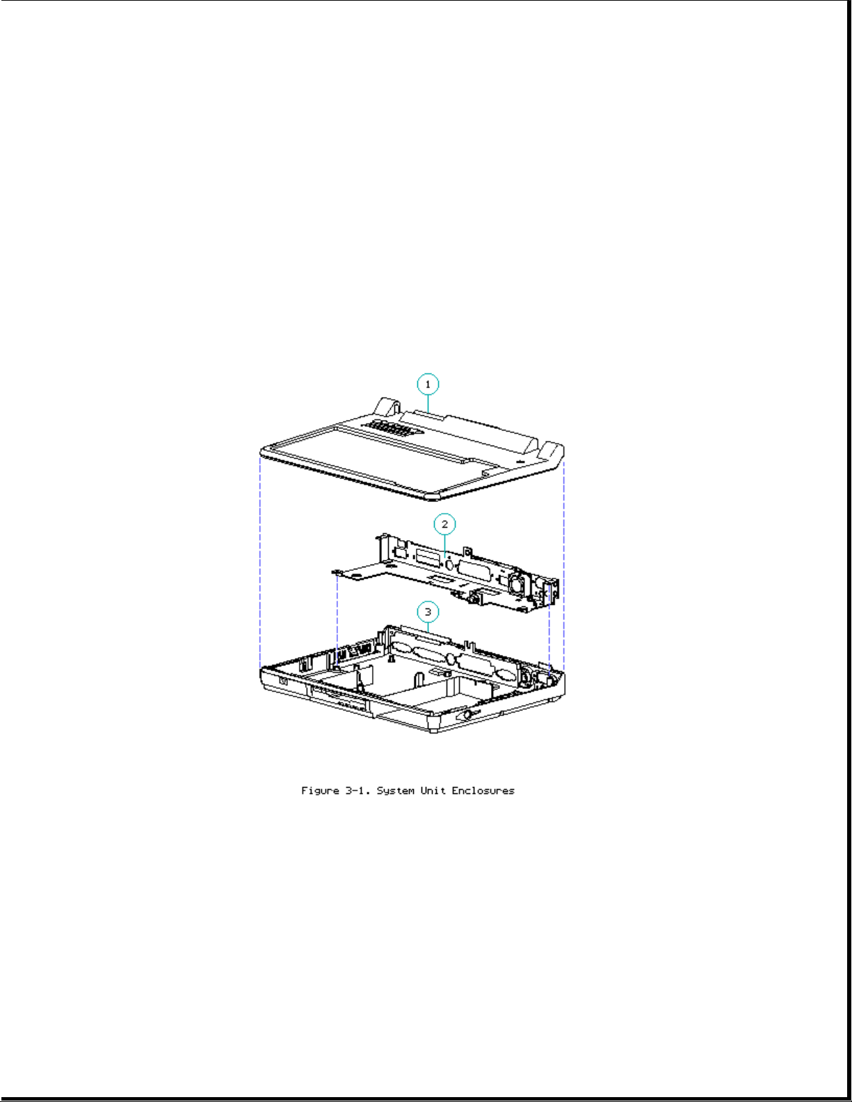
Chapter 3 - Compaq LTE Elite Illustrated Parts Catalog
Introduction
This chapter provides illustrated parts breakdowns and identifies the spare
parts for the Compaq LTE Elite Family of Personal Computers, including the
Compaq MiniStation/EN and the Compaq MiniStation/TR.
Refer to Chapter 8 for spare part information for the Compaq SmartStation.
3.1 System Unit Enclosures
Table 3-1. System Unit Enclosures
===========================================================================
Description Spare Part Number
===========================================================================
1. Keyboard Cover 149594-001
---------------------------------------------------------------------------
2. Input/output (I/O) Bracket 149706-001
Includes:
- I/O bracket
- Fan
Page 82
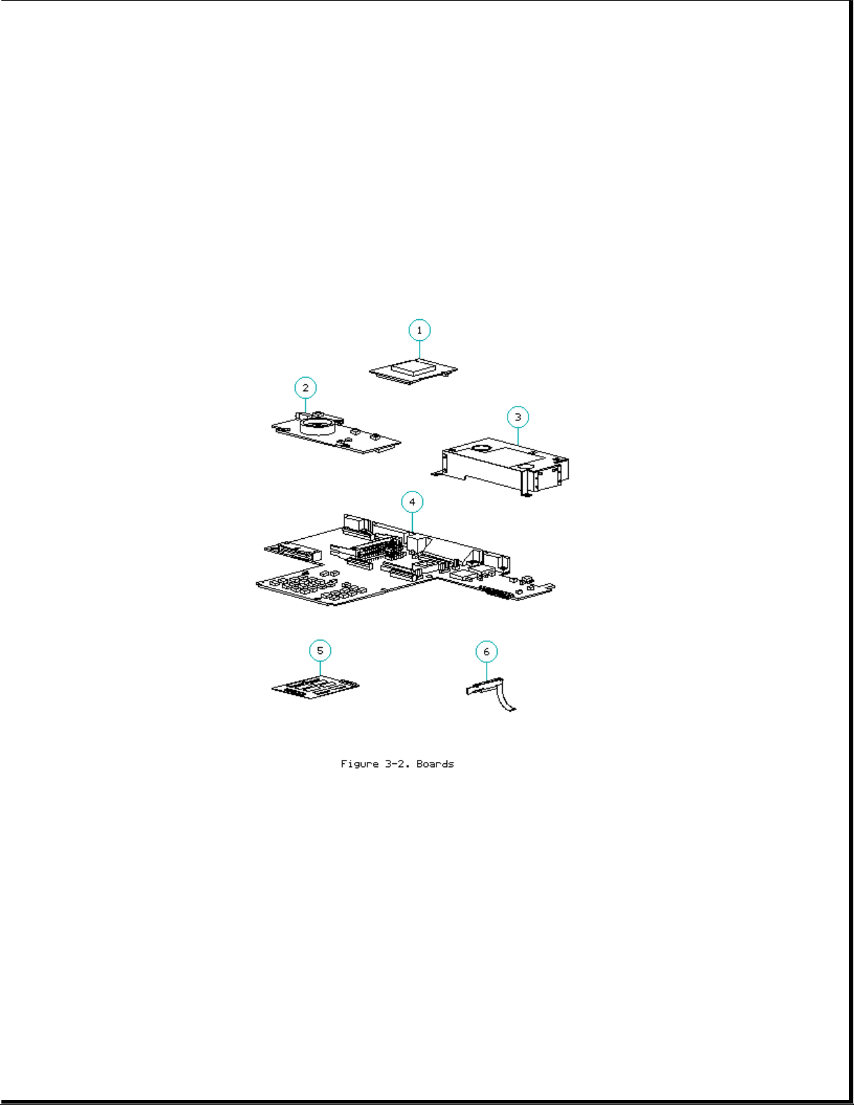
---------------------------------------------------------------------------
3. Base Enclosure 149595-001
Includes the following installed parts:
- Battery pack release latch assembly (button, latch, and spring)
- Hard drive release latch assembly (button, latch, and spring)
- PCMCIA compartment door and spring
- Automobile adapter door
- Hard drive compartment door
===========================================================================
3.2 Boards
Table 3-2. Boards
===========================================================================
Description Spare Part Number
===========================================================================
1. Processor Board
- 486 DX4/75 MHz 194147-001
- 486 DX2/50 MHz 194146-001
- 486 DX2/40 MHz 194149-001
2. Power Interface (PIB) Board 194058-001
(includes display switch spring)
Page 83

3. Internal AC Power Supply 149527-001
(includes right hinge cover)
4. System Board:
- 4 MB 194007-001
- 8 MB 149508-001
5. Memory Expansion Board (70 ns):
- 4 MB 194188-001
- 8 MB 194189-001
- 16 MB 196799-001
6. LED Cable Assembly 149707-001
7. Trackball Board (includes trackball) 149597-001 *
8. Inverter Board (Refer to Table 3-3.) *
---------------------------------------------------------------------------
* Not shown
===========================================================================
3.3 Model Specific Display Parts
Page 84

Table 3-3. Display - Model-Specific Display Parts
===========================================================================
Spare Part Number
===========================================================================
1. Display Bezel
9.5 Inch Color TFT 197855-001
8.4 Inch TFT 194040-001
9.5 Inch Black and White TFT 149603-001
9.5 Inch Color STN 149779-001 *
10.4 Inch Color TFT 197940-001
3. Display Panel
9.5 Inch Color TFT 149589-001 **
8.4 Inch Color TFT 194039-001
9.5 Inch Black and White TFT 138041-001
9.5 Inch Color STN 149736-001
10.4 Inch Color TFT 197920-001
4. Inverter Board
9.5 Inch Color TFT 149589-001 **
8.4 Inch Color TFT 149587-001
9.5 Inch Black and White TFT 194141-001
9.5 Inch Color STN 149735-001
10.4 Inch Color TFT 196877-001
Page 85

5. Display Cable
9.5 Inch Color TFT 149589-001 **
8.4 Inch Color TFT 149604-001
9.5 Inch Black and White TFT 197632-001
9.5 Inch Color STN 149737-001
10.4 Inch Color TFT 197909-001
8. Display Ground Cable
9.5 Inch Color TFT 149589-001 **
8.4 Inch Color TFT 197857-001
9.5 Inch Black and White TFT 194637-001 ***
9.5 Inch Color STN 194637-001 ***
10.4 Inch Color TFT 197937-001
9. Display Enclosure
9.5 Inch Color TFT 149589-001 **
8.4 Inch Color TFT 149596-001
9.5 Inch Black and White TFT 197664-001
9.5 Inch Color STN 149596-001
10.4 Inch Color TFT 197937-001
--------------------------------------------------------------------------
* Two display bezels are provided for the 9.5" color STN display. Use the
bezel that lines up property with the existing panel.
** The spare display panel, inverter board, display cable, display ground
cable, and display enclosure for the 9.5" color TFT display come
preinstalled in a display assembly to ensure compatibility and optimize
the display quality.
*** The ground cable used on the 9.5" black-and-white TFT and the 9.5"
color STN displays may be 2 inches shorter than the one used in the
other models. In addition, the shorter ground cable may not have a
ground clip inside the display enclosure.
===========================================================================
Common Display Parts
===========================================================================
Description Spare Part Number
===========================================================================
2. Control Slide(s) (Refer to Table 3-10.)
6. Trackball Board 149597-001
7. Clutches (left and right) 149592-001
10. Display Latches (Refer to Table 3-8.)
*****
11. Compaq Display Logos **** 149605-001 *****
---------------------------------------------------------------------------
**** The Compaq display logos are also included with the display
enclosure.
***** Not Shown.
===========================================================================
IMPORTANT: Each display type must use the exact panel, cable, inverter
board, and bezel that are listed above to ensure proper
performance.
Page 86

3.4 Mass Storage Devices
Table 3-4. Mass Storage Devices
===========================================================================
Description Spare Part Number
===========================================================================
1. 3.5-inch, 1.44 MB Diskette Drive 149749-001
2. Diskette Drive Cable 149588-001
3. Removable Hard Drive
- 810 MB 177819-001
- 510 MB 194086-001
- 340 MB 149591-001
- 250 MB 149750-001
- 170 MB 194079-001
4. Hard Drive Carrying Case 149783-001
===========================================================================
3.5 Batteries
Page 87

Table 3-5. Batteries
===========================================================================
Description Spare Part Number
===========================================================================
1. NiMH Battery Pack 149599-001
2. Auxiliary Battery 149598-001
===========================================================================
3.6 Cables And Connectors
Page 88

Table 3-6. Cables and Connectors
===========================================================================
Description Spare Part Number
===========================================================================
1. PCMCIA Ejector Rails
(includes PCMCIA spacer tool) 196454-001
2. LED Cable Assembly 149707-001
3. Diskette Drive Cable 149588-001
4. Power Cord
- U.S./Canadian 149710-001
- European 149710-002 *
- U.K. 149710-003 *
- Japanese 149710-007 *
- Australian 149710-008 *
5. ZIF Connector Slides 140069-001 *
6. Display Cable (Refer to Table 3-3.) *
7. Display Ground Cable (Refer to Table 3-3.) *
--------------------------------------------------------------------------* Not shown.
Page 89

===========================================================================
3.7 Keyboards
Table 3-7. Keyboards
===========================================================================
Description Spare Part Number
===========================================================================
U.S. English 149608-001
U.K. English 149608-003 *
German 149608-004 *
French 149608-005 *
Italian 149608-006 *
Spanish 149608-007 *
Danish 149608-008 *
Norwegian 149608-009 *
Swedish/Finnish 149608-010 *
Swiss 149608-011 *
French Canadian 149608-012 *
Portuguese 149608-013 *
Latin American 149608-016 *
Belgian 149608-018 *
Japanese 149608-019 *
Page 90

--------------------------------------------------------------------------* Not shown.
===========================================================================
3.8 Latches Kit
Table3-8. Latches Kit
===========================================================================
Description Spare Part Number
===========================================================================
Kit includes: 149600-001
Battery release latch assembly
(button, latch, and spring)
Hard drive release latch assembly
(button, latch, and spring)
Right display latch, latch spring, and button
Left display latch, latch spring, and button
===========================================================================
3.9 Doors Kit
Table3-9. Doors Kit
===========================================================================
Description Spare Part Number
===========================================================================
Kit includes: 194158-001
Input/output (I/O) connector cover
Automobile adapter door
Hard drive compartment door
PCMCIA compartment door
PCMCIA compartment door spring
Memory access cover
===========================================================================
3.10 Miscellaneous Plastics Kit
Table3-10. Miscellaneous Plastics Kit
===========================================================================
Description Spare Part Number
===========================================================================
Kit includes: 194157-001
Control slides for TFT display (Quantity = 3)
Control slides for STN display (Quantity = 6)
Rubber feet (Quantity = 4)
Right hinge cover
Left hinge cover
Display screw covers
===========================================================================
3.11 Miscellaneous Small Mechanical Parts Kit
Page 91

Table3-11. Miscellaneous Small Mechanical Parts Kit
===========================================================================
Description Spare Part Number
===========================================================================
Kit includes: 149781-001
Auxiliary battery bracket
Diskette drive shield
Battery pack eject spring
Power interface board (PIB) mounting bracket
Power interface board (PIB) mounting bracket insulator
Hard drive security clips (Quantity = 2)
Display switch spring
Trackball shield
Hard drive lock labels (Quantity = 5)
===========================================================================
3.12 Compaq LTE Elite Screws And Fasteners Kit
Table3-12a. Compaq LTE Elite Screws and Fasteners Kit
===========================================================================
Description Spare Part Number
===========================================================================
Compaq LTE Elite Screws and Fasteners Kit
(Quantity = 25) 149763-001
===========================================================================
Table 3-12b. Compaq LTE Elite Screw and Fastener Locations
===========================================================================
Where Used Description Type Drive (in.-lbs.) Qty Number
===========================================================================
DISPLAY ENCLOSURE AND BOARDS:
Bezel to Screw, Truss, T8/SL 3.0 4 144864-004
display M2.5 x 6.0 MA,
enclosure CS
(2 through
clutches)
--------------------------------------------------------------------------Clutches to Screw, Truss, T8/SL 3.0 2 144864-004
display M2.5 x 6.0 MA,
enclosure CS
--------------------------------------------------------------------------Panel to Screw, Truss, T8 3.0 4 121187-006
display M3.0 x 6.0 MA,
enclosure CS
--------------------------------------------------------------------------Inverter Screw, Truss, T8/SL 2.0 2 144863-005
board to M2.0 x 6.0 MA,
display CS
enclosure
--------------------------------------------------------------------------Trackball Screw, Truss, T8 2.0 2 144863-005
board to M2.0 x 6.0 MA,
display CS
enclosure
---------------------------------------------------------------------------
Maximum
Torque Ref. Part
Page 92

SYSTEM UNIT BOARDS/CONNECTORS:
Internal AC Screw, Truss, T8/SL 3.0 2 144864-004
power supply M2.5 x 6.0 MA, T
to system CS
board
(on top)
--------------------------------------------------------------------------Internal AC Screw, Truss, T8/SL 3.0 2 144864-004
power supply M2.5 x 6.0 MA,
to system CS
unit
enclosure
(at rear)
===========================================================================
Maximum
Torque Ref. Part
Where Used Description Type Drive (in.-lbs.) Qty Number
===========================================================================
Serial, Screwlock, Hex, 3/16" 4.0 8 106902-005
parallel, 4-40 sems, MA,
external ext. tooth, CS
monitor, F
external
options
connectors
(at rear)
--------------------------------------------------------------------------PIB/PCMCIA Screw, Truss, T8/SL 2.0 2 144863-007
rails to M 2.0 x 20.5 MA,
system unit CS
enclosure
(long screws)
--------------------------------------------------------------------------Keyboard to Screw, Truss, T8/SL 3.0 2 144864-004
system unit M2.5 x 6.0 MA,
enclosure CS
--------------------------------------------------------------------------System board Screw, Truss, T8/SL 3.0 6 144864-004
to system M 2.5 x 6.0 MA,
unit CS
enclosure
--------------------------------------------------------------------------PIB to Screw, Truss, T8/SL 2.0 3 144863-005
PCMCIA M2.0 x 6.0 MA,
connector CS
(short
screw)
--------------------------------------------------------------------------Keyboard/ Screw, Truss, T8/SL 3.0 1 144864-004
mouse M2.5 x 6.0 MA,
connector CS
--------------------------------------------------------------------------Automobile Screw, Truss, T8/SL 2.0 2 144863-005
adapter M2.0 x 6.0 MA,
connector CS
to system
unit
enclosure
---------------------------------------------------------------------------
Page 93

SYSTEM UNIT ENCLOSURE:
Keyboard Screw, Truss, T8/SL 3.0 5 144864-006
cover to M2.5 x 21.0 MA,
system unit CS
enclosure
(on bottom)
--------------------------------------------------------------------------Keyboard Screw, Truss, T8/SL 3.0 1 144864-004
cover to M2.5 x 6.0 MA,
system unit CS
enclosure
(at rear)
--------------------------------------------------------------------------Clutches to Screw, Truss, T8/SL 3.0 4 144864-003
system unit M2.5 x 10.0 MA,
enclosure CS
===========================================================================
3.13 Tools
Table 3-13. Tools
===========================================================================
Page 94
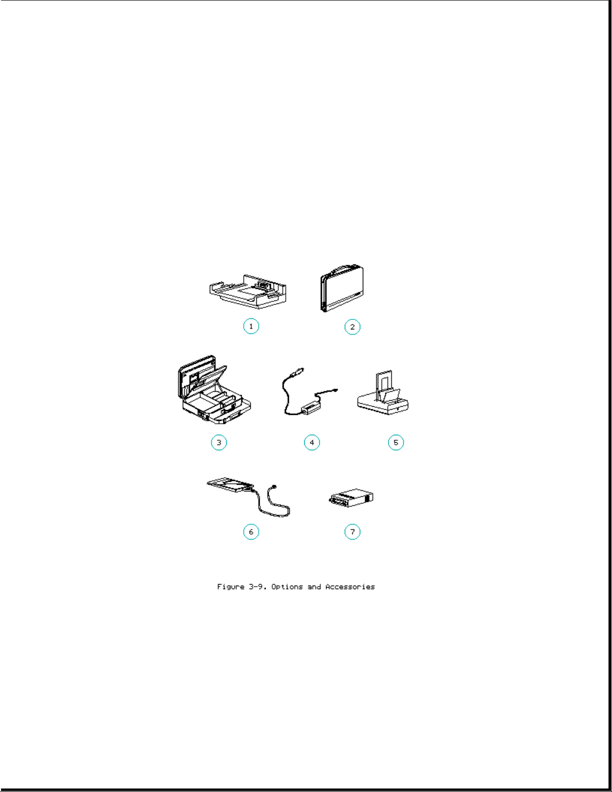
Description Spare Part Number
===========================================================================
1. Trackball Removal Tool 194041-001
---------------------------------------------------------------------------
2. Special Service Aids Kit 100767-001
Includes:
3. Connector Removal Tool
4. Display Bezel Removal Tool
5. Loopback Plugs *
--------------------------------------------------------------------------* Not shown.
===========================================================================
3.14 Options
Table 3-14. Compaq LTE Elite Options and Accessories
===========================================================================
Description Spare Part Number
===========================================================================
1. Compaq LTE Lite Desktop Expansion Base 199027-001
Upgrade Kit ** (includes Network Install
Diskette) (192307-001)
---------------------------------------------------------------------------
Page 95

2. Carrying Case (138058-001) 121423-001
---------------------------------------------------------------------------
3. Briefcase (137608-001) 129930-001
---------------------------------------------------------------------------
4. Automobile Adapter (197636-001) 194626-001
---------------------------------------------------------------------------
5. External Battery Fastcharger/Conditioner 198866-001
(196825-001)
---------------------------------------------------------------------------
6. PCMCIA Modem (data/fax):
Compaq SpeedPaq 144/P Modem 198109-001 194131-001
Compaq PCMCIA 2400/9600 Data and Fax Modem 194098-001 ***
(198116-001)
---------------------------------------------------------------------------
7. CD ROM Adapter (16 Bit with 25" cable) 121467-002
(142519-001)
---------------------------------------------------------------------------
8. Slipcase (147709-001) 197635-001 ***
---------------------------------------------------------------------------
9. Battery Pack (149729-001) 149599-001 ***
(Refer to Table 3-5.)
---------------------------------------------------------------------------
10. Display Upgrade Kit (9.5" Color TFT) 149589-001 ***
(194037-001) (Refer to Table 3-3.)
---------------------------------------------------------------------------
11. Hard Drive
340 MB (198968-001) 149591-001 ***
510 MB (197628-001) 194086-001 ***
810 MB (149685-005) 163420-001 ***
(Refer to Table 3-4.)
---------------------------------------------------------------------------
12. Memory Expansion Board (70 ns):
4 MB (199013-001) 194188-001 ***
8 MB (199014-001) 194189-001 ***
16 MB (196806-001) 196799-001 ***
(Refer to Table 3-2.)
---------------------------------------------------------------------------
13. Processor Board
486 DX4/75 MHz (194048-001) 194147-001 ***
(Refer to Table 3-2.)
---------------------------------------------------------------------------
* The Compaq option part number is provided in the description column
for reference only. When ordering a spare part, use the number listed
in the Spare Part Number column.
** Compaq LTE Lite Desktop Expansion Base Upgrade Kit modifies a desktop
expansion base to allow a Compaq LTE Elite to dock with it.
The upgrade kit is a user-installed option.
*** Not shown.
===========================================================================
3.15 Compaq Ministation Convenience Bases
Page 96

>>>>>>>>>>>>>>>>>>>>>>>>>>>>>>>>> WARNING <<<<<<<<<<<<<<<<<<<<<<<<<<<<<<<<<
To avoid the risk of electric shock, the I/O bracket overlay must be
installed on the I/O bracket of the Compaq MiniStation.
>>>>>>>>>>>>>>>>>>>>>>>>>>>>>>>>>>>>><<<<<<<<<<<<<<<<<<<<<<<<<<<<<<<<<<<<<<
Table 3-15. Compaq MiniStation Convenience Bases
===========================================================================
Description Spare Part Number
===========================================================================
1. Monitor Support Cover 198860-001
---------------------------------------------------------------------------
2. Plastics and Mechanical Parts Kit, 195564-001
including:
3. Top enclosure
4. Docking mechanism
5. Bottom enclosure
6. Ventilation chamber
---------------------------------------------------------------------------
7. Power Cord
- U.S./Canadian 149710-001
- European 149710-002 *
- U.K. 149710-003 *
- Australian 149710-008 *
Page 97

---------------------------------------------------------------------------
8. SCSI/NIC Board **:
- SCSI/Ethernet Board 195566-001
- SCSI/Token Ring Board 196782-001
---------------------------------------------------------------------------
9. Power Supply Board Kit, including: 195567-001
10. Standoff
11. I/O bracket overlays
(Quantity = 2) ***
12. Power Supply Board with I/O
bracket
---------------------------------------------------------------------------
13. Tilt Base 198861-001
---------------------------------------------------------------------------
14. Compaq MiniStation Screws and Fasteners Kit 195565-001 *
--------------------------------------------------------------------------* Not shown.
** The Compaq MiniStation/EN uses a SCSI/Ethernet board and the Compaq
MiniStation/TR uses a SCSI/Token Ring board.
*** The I/O bracket overlay is installed over the connectors on the back of
the I/O bracket of the power supply board. The Compaq MiniStation/EN
and the Compaq MiniStation/TR each use a different overlay. Both
overlays are provided with the power supply board.
===========================================================================
3.16 Software Diskettes
Table3-16. Software Diskettes
===========================================================================
Description Spare Part Number
===========================================================================
Compaq Diagnostics Diskette 109728-001
EZ-SCSI Configuration Software Diskette 146994-001
EZ Tape 122098-001
PCMCIA Software Kit 198821-001
ROMPaq Upgrade Diskette Kit 129899-001
Portables ROMPaq Upgrade Diskette 181088-001
Supplemental Programs Diskette
(includes EXTDISK) [English] 199976-001
Video Software Kit 181031-001
===========================================================================
3.17 Documentation
Table3-17. Documentation
===========================================================================
Description Spare Part Number
===========================================================================
Compaq LTE Elite/Compaq SmartStation Maintenance 149601-001
and Service Guide
---------------------------------------------------------------------------
Online User's Guide:
English 194641-001
German 194641-041
Page 98

French 194641-051
Italian 194641-061
Spanish 194641-071
Swedish 194641-101
Dutch 194641-331
---------------------------------------------------------------------------
Quick Setup card and Beyond Setup guide:
English 149709-001
German 149709-041
French 149709-051
Italian 149709-061
Spanish 149709-071
Danish 149709-081
Norwegian 149709-091
Swedish 149709-101
Latin American Spanish 149709-161
Japanese 149709-191
Brazilian Portuguese 149709-201
Dutch 149709-331
Finnish 149709-351
---------------------------------------------------------------------------
Compaq MiniStation Installation Guide
English 196786-001
German 196786-041
French 196786-051
Italian 196786-061
Spanish 196786-071
Swedish 196786-101
Dutch 196786-331
---------------------------------------------------------------------------
Compaq Service Quick Reference Guide (Quantity = 5) 106954-001
---------------------------------------------------------------------------
Compaq QuickFind:
U.S./Canadian 137906-00X
International (other than U.S./Canadian):
Authorized Compaq Reseller Version 137907-00X
End User Version 137908-00X
---------------------------------------------------------------------------
Compaq EZ-SCSI Software Reference
English 196785-002
German 196785-042
French 196785-052
===========================================================================
3.18 Shipping Box
Table3-18. Shipping Box
===========================================================================
Description Spare Part Number
===========================================================================
Compaq LTE Elite Shipping Box 149593-001
===========================================================================
Page 99

Chapter 4 - Compaq LTE Elite Removal and Replacement Procedures
Introduction
This chapter provides subassembly level removal and replacement procedures
for the Compaq LTE Elite. Unless otherwise specified, the steps for
replacement procedures are the reverse of the steps for the removal
procedures.
After completing all necessary removal and replacement procedures, run POST
and Computer Setup to verify that all components operate properly (refer to
Chapter 2).
4.1 Precautions
This section covers precautions that must be followed when servicing the
computer.
Electrostatic Discharge (ESD)
A sudden electrostatic discharge (ESD) can destroy static-sensitive devices
or microcircuitry. Use proper packaging and grounding techniques to prevent
damage. Refer to Appendix E for more information on ESD.
>>>>>>>>>>>>>>>>>>>>>>>>>>>>>>>>> CAUTION <<<<<<<<<<<<<<<<<<<<<<<<<<<<<<<<<
Electrostatic discharge can damage electronic components. Be sure that you
are properly grounded before performing any maintenance and service
procedures.
>>>>>>>>>>>>>>>>>>>>>>>>>>>>>>>>>>>>><<<<<<<<<<<<<<<<<<<<<<<<<<<<<<<<<<<<<<
Cables
Use the following precautions when handling cables to avoid irreparable
damage to the cable or the computer:
o Always handle cables by their connectors.
o Avoid bending, twisting, or pulling on the cables.
o Apply the minimum required force when seating or unseating the cables
from their connectors.
o Place cables in such a manner that they cannot be caught or snagged by
parts being removed or replaced.
o Handle flex cables with extreme care, as they can easily tear.
ZIF Connectors
The computer uses zero insertion force (ZIF) connectors for the following
connections:
Page 100
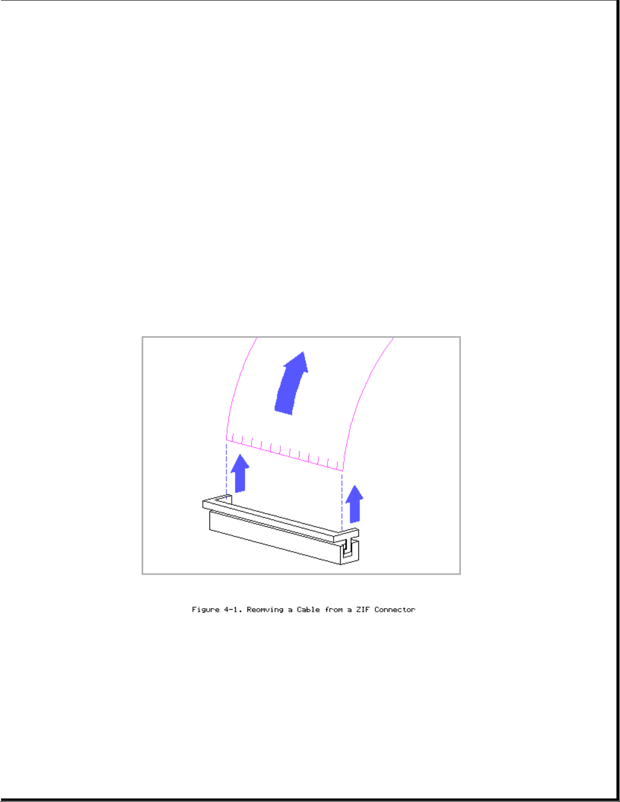
o Keyboard to system board
o Diskette drive to system board
o Display cable to system board
o Display cable to display panel (black-and-white TFT only)
To remove a cable from a ZIF connector, lift both corners of the ZIF
connector slide simultaneously with constant light force until the
connector slide releases, then remove the cable (Figure 4-1).
>>>>>>>>>>>>>>>>>>>>>>>>>>>>>>>>> CAUTION <<<<<<<<<<<<<<<<<<<<<<<<<<<<<<<<<
A ZIF connector and its attached cable can be easily damaged. Handle only
the connector slide when removing or replacing a cable. Never pull or twist
on the cable while it is connected.
>>>>>>>>>>>>>>>>>>>>>>>>>>>>>>>>>>>>><<<<<<<<<<<<<<<<<<<<<<<<<<<<<<<<<<<<<<
IMPORTANT: Due to space limitations inside the system unit, the display
cable cannot be removed from the system board ZIF connector
using the standard removal technique. To remove the cable, the
connector removal tool must be used. Refer to "Removing the
Display Assembly" in Section 4.9.
 Loading...