

Page 1

Please check out our eBay auctions for more great
deals on Factory Service Manuals:
Page 2

Notice
The information in this guide is subject to change without notice.
Compaq Computer Corporation shall not be liable for technical or editorial
errors or omissions contained herein; nor for incidental or consequential
damages resulting from the furnishing, performance, or use of this
material.
This guide contains information protected by copyright. No part of this
guide may be photocopied or reproduced in any form without prior written
consent from Compaq Computer Corporation.
Copyright 1995, 1996 Compaq Computer Corporation.
All rights reserved. Printed in the U.S.A.
Compaq, Deskpro, LTE, Contura, Presario, ProLinea
Registered U. S. Patent and Trademark Office.
LTE 5000 is a trademark of Compaq Computer Corporation.
Contura Registered in the Philippines Patent Office.
Microsoft, MS-DOS, and Windows are registered trademarks of Microsoft
Corporation.
The software described in this guide is furnished under a license
agreement or nondisclosure agreement. The software may be used or copied
only in accordance with the terms of the agreement.
Product names mentioned herein may be trademarks and/or registered
trademarks of their respective companies.
MAINTENANCE AND SERVICE GUIDE
COMPAQ LTE 5000 FAMILY OF PERSONAL COMPUTERS
First Edition (September 1995)
Second Edition (November 1996)
Documentation Part Number 213583-002
Spare Part Number 213622-002
Page 3
Chapter 1. Product Description
1.1 Computer Features and Models
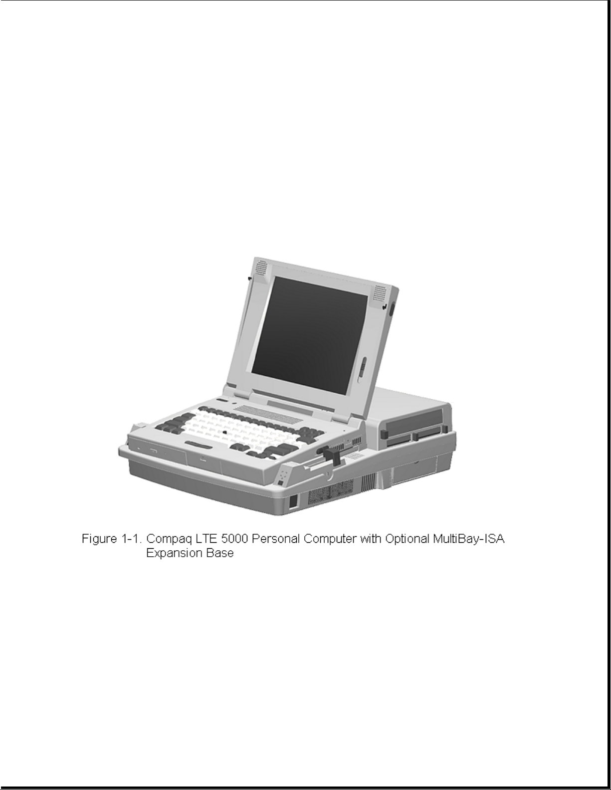
The Compaq LTE 5000 Family of Personal Computers introduces a new
generation of performance notebook computers with advanced modularity,
Pentium processors with 64-bit architecture, PCI local bus graphics, and
extensive multimedia support. This full- function family of notebook
computers allows desktop functionality and connectivity via an optional
expansion base.
1.1.1 Computer Features
The Compaq LTE 5000 Family of Personal Computers has the following
standard features:
o Extensive multimedia support with integrated 16-bit digital stereo audio
(Microsoft Windows Sound System and SoundBlaster Pro compatible), dual
speakers, microphone, full motion video support, optional CD-ROM drive,
and optional MPEG and TV Video Adapter
o 75, 90, 100, 120, 133, or 150-MHz Intel Pentium processor with 64-bit
architecture
Page 4

o 8 or 16 MB of RAM, expandable to 72 or 80 MB
o 512 KB of 64-bit write-back, synchronous, level-2 cache memory available
on the LTE5400 model; 256 KB of 64-bit write-back, synchronous,
level-2 cache memory available on all other models
o Upgradable flash ROM BIOS
o High-performance 32-bit PCI local bus graphics with hardware-assisted
Motion Video Acceleration (MVA)
o Color TFT VGA or SVGA, CSTN VGA or SVGA, or CTFT 1024 x 768 display
panels
o Keyboard with built-in EasyPoint II pointing device and mouse buttons
o Removable hard drive
o MultiBay modular device bay that supports a CD-ROM drive, a second hard
drive, a second battery pack, or diskette drive, and a full-length ISA
slot that allows addition of an ISA expansion board (ISA slot available
with MultiBay ISA Expansion Base only)
o Two Type III PC Card (PCMCIA) slot that supports one Type III, two Type
I, or two Type II PC Cards, LAN connection or data/fax modem
o Infrared port for IrDA wireless data transfer, printing, and drive
synchronization
o Ports and connectors for external equipment (see Section 1.3)
o Preinstalled software
o Security features
o Desktop functionality available with the optional Compaq LTE 5000
MultiBay Expansion Base or MultiBay ISA Expansion Base.
1.1.2 Computer Models
The Compaq LTE 5000 Family of Personal Computers is available in the
models shown in Table 1-1.
Table 1-1. Compaq LTE 5000 Family of Personal Computers Models
===========================================================================
Model Processor Display Hard Drive CD-ROM Drive
===========================================================================
LTE 5000 Model Pentium/75 10.4-inch 510 MB Optional
510 CSTN CSTN/VGA
--------------------------------------------------------------------------LTE 5000 Model Pentium/75 11.3-Inch 810 MB Optional
810 CSTN CSTN/SVGA
--------------------------------------------------------------------------LTE 5000 Model Pentium/75 10.4-Inch 810 MB Optional
810 CTFT CTFT/VGA
--------------------------------------------------------------------------LTE 5100 Model Pentium/90 10.4-Inch 810 MB Optional
810 CTFT CTFT/SVGA
--------------------------------------------------------------------------LTE 5100 Model Pentium/90 10.4-Inch 810 MB Yes
Page 5

810 CD CTFT CTFT/SVGA
--------------------------------------------------------------------------LTE 5150 Model Pentium/100 11.3-inch 810 MB Yes
810 CSTN 800 CTFT/SVGA
x 600
--------------------------------------------------------------------------LTE 5200 Model Pentium/120 10.4-inch 1.35 GB Optional
1350 CTFT CTFT/SVGA
--------------------------------------------------------------------------LTE 5250 Model Pentium/120 10.4-inch 810 MB Yes
810 CTFT CTFT/SVGA
800 x 600
--------------------------------------------------------------------------LTE 5280 Model Pentium/120 11.3-inch 810 MB Yes
810 CTFT CTFT/SVGA
800 x 600
--------------------------------------------------------------------------LTE 5280 Model Pentium/120 11.3-inch 1.35 GB Yes
1350 CTFT CTFT/SVGA
800 x 600
--------------------------------------------------------------------------LTE 5300 Model Pentium/133 12.1-inch 1.35 GB Yes
1350 CTFT CTFT/SVGA
800 x 600
--------------------------------------------------------------------------LTE 5300 Model Pentium/133 12.1-inch 2.16 GB Yes
2160 CTFT CTFT/SVGA
800 x 600
--------------------------------------------------------------------------LTE 5380 Model Pentium/133 12.1-inch 2.16 GB Yes
2160 CTFT CTFT/10 X 7
1024 x 768
--------------------------------------------------------------------------LTE 5400 Model Pentium/150 12.1-inch 2.16 GB Yes
2160 CTFT CTFT SVGA
800 x 600
===========================================================================
1.1.3 Preinstalled Software
The computer can have either Windows 3.1 or Windows 95 installed.
Windows 3.1 Software Components
The following software is preloaded if Windows 3.1 is installed:
o MS-DOS 6
o Microsoft Windows 3.1
o Cirrus GD-754x Video Driver
o TEAC CD-40E CD-ROM Driver and CD Audio Player for DOS
o ESS Audio Driver and Audio Clip Library
o Compaq Sound System Version 1.70
o Compaq Network Interface Drivers
Page 6

o Compaq PCMCIA 3.14
o Logitech Mouse Ware 6.46
o PUMA TranXit Version 1.03
o Microsoft Video for Windows 1.10e (Runtime version)
o Machine Check Version 1.1 (MACHCHK.SYS)
o SystemSoft Suspend-To-Disk Utility 2.20.00 (0VMAKFIL.EXE)
o Compaq Supplementary Programs
o Microsoft Supplementary Programs
o SAFETY & COMFORT GUIDE
o COMPAQ DICTIONARY
o COMPAQ USER'S GUIDE
o ONLINE OPTIONS CATALOG
o Compaq Diagnostics for Windows 1.05
o CompuServe WinCIM (1.4/1.2/1.31D/1.31F)
o America Online for Windows (North America only)
Windows 95 Software Components
The following software is preloaded if Windows 95 is installed:
o Cirrus Logic GD-754x Video Driver
o TEAC CD-40E CD-ROM Driver
o Compaq PCMCIA 3.14 Installer for Windows 95
o Logitech Mouse Ware 6.50
o Machine Check Version 1.1 (MACHCHK.SYS)
o SystemSoft Suspend-To-Disk Utility 2.20.00 (0VMAKFIL.EXE)
o Microsoft Infrared Monitor and Direct Cable Connect
o SAFETY & COMFORT GUIDE
o COMPAQ DICTIONARY
o COMPAQ ONLINE USER'S GUIDE
o ONLINE OPTIONS CATALOG
1.1.4 Intelligent Manageability
Intelligent Manageability combines innovative hardware technology with PC
Page 7

LAN management tools from Compaq and other leading vendors to make Compaq
portable computers easier to inventory, troubleshoot, and protect.
Asset Management
AssetControl is asset management software designed to cut the time and
cost of conducting a physical inventory of personal computers, key
components, and monitors. AssetControl is preinstalled on portable
computers, key components, and monitors that support the Video Electronics
Standards Association Data Display Channel (VESA DDC) and Extended Display
Identification Data (EDID) standards.
AssetControl features make it easy and inexpensive to maintain an
accurate, up-to-date inventory. Detailed inventory information, including
manufacturer, model, serial number, asset tag, and ROM revision level can
be viewed, printed, or saved electronically using Compaq Insight Personal
Edition or Compaq Insight Manager.
Compaq Insight Personal Edition refers to Intelligent Manageability
software that diagnoses portable computer hardware, monitors the internal
system temperature and IntelliSafe hard drive, and then displays a
prefailure warning message on detecting a system temperature or hard drive
fault.
Compaq Insight Manager refers to Information Manageability software that
helps manage servers and personal computers on a network. Compaq Insight
Manager features intelligent monitoring and alerting, remote maintenance,
and visual control of network resources.
Fault Management
Fault Management is a utility designed to help prevent the loss of
critical data. This feature is available only in the 2.16GB DFP (SMART
system compliant drives). Fault Management has the following features:
o SMART (IntelliSafe) hard drive - Constantly monitors hard drive activity
to predict failures before they occur.
o Temperature sensing - Hardware and software that tracks the internal
temperature of the computer and displays a warning message when the
normal range is exceeded.
Compaq Insight Personal Edition displays a pop-up message to notify you
when a hard drive or system temperature fault is detected. If the computer
is connected to a network managed by Compaq Insight Manager, fault notices
are also sent to the network management application.
Security Management
The security management utility provides a set of security features to
protect the computer and data from unauthorized access.
o Passwords - Prevents unauthorized access to information stored on the
computer or network.
o Drive security - Prevents starting the computer from the diskette drive
and reading information from the diskette drive.
o Device disabling - Prevents unauthorized data transfer over fax/modems,
serial ports, parallel ports, and infrared ports.
Page 8

1.1.5 Security Features
The computer has the following security features:
o Ability to secure drives in the dedicated hard drive bay and computer
MultiBay
o Ability to secure the computer and either MultiBay Expansion Base to an
immovable object with an optional cable lock
o Ability to establish power-on and setup passwords and to disable ports
and devices from the Security menu in Computer Setup
1.1.6 Power Management
Power Management offers three levels of power conservation:
o High: Provides the maximum amount of power conservation and the maximum
battery operating time from a single charge.
o Medium: Provides a balance between performance and battery life (factory
default).
o Custom: Conserves power according to user-specified timeout settings.
The conservation level sets the timeouts for Standby (Suspend),
Hibernation, drives, and screens. Use the Fn+F7 hotkeys to toggle off and
on the power management settings in Computer Setup and Windows Power
Properties.
Selecting to disable the infrared port under the Security menu also
conserves power.
Chapter 1.2 Computer Options
The options that are available from Compaq for the computer are described
in the following sections.
1.2.1 MultiBay Expansion Base and MultiBay ISA Expansion Base
The MultiBay Expansion Base and the MultiBay ISA Expansion Base provide
two additional MultiBay device bays, two PC Card Type III slots,
integrated Ethernet, integrated stereo speakers, and computer I/O port
replication. The expansion bases are described in Section 1.5. When the
computer is docked in an expansion base, the total system functionality
includes:
o Support for up to three MultiBay devices simultaneously
o Overall system support for up to four hard drives or two diskette drives
o Up to three CD-ROM drives installed as follows:
- Three CD-ROM drives: The two in the expansion base must be used for
data; the CD-ROM drive in the computer can then be used for audio or data.
Page 9

- Two CD-ROM drives: You can have one in the expansion base and one in
the computer; either drive can be data or audio. If both drives are in
the expansion base, they must be for data only.
- One CD-ROM drive: It can be either data or audio and in either the
computer or expansion base.
o Two Type III PC Card slots
o Overall system support for up to four PC cards
o Charging of up to four battery packs
The MultiBay ISA Expansion Base provides the same functionality as the
MultiBay Expansion Base, with the following additional features:
o One ISA Expansion slot allows ability to add a full-length ISA expansion
board
o Additional ventilation exhausts on both sides of the expansion base for
increased ventilation
o High performance stereo speakers and new audio bass ports on both sides
of the expansion base for "PremierSound" CD-quality audio
1.2.2 System Memory Options
The main memory subsystem supports a minimum standard 8 MB or 16 MB of
DRAM, expandable to a maximum of 72 or 80 MB. The minimum standard DRAM is
integrated on the processor board. The upgrade DRAM is accomplished with
memory expansion boards that are available in 8, 16, 32, and 64 MB
increments. The memory expansion boards require no special tools for
installation and can be installed by the inexperienced user. System memory
can be upgraded according to the schedule in Table 1-2:
Table 1-2. Memory Upgrade Schedule
===========================================================================
Base Memory Memory Expansion Board Total Memory
===========================================================================
8/16 MB None 8/16 MB
8/16 MB 8 MB 16/24 MB
8/16 MB 16 MB 24/32 MB
8/16 MB 32 MB 40/48 MB
8/16 MB 64 MB 72/80 MB
===========================================================================
1.2.3 Mass Storage Options
The following mass storage options are available for the computer:
Page 10

o 3.5-inch 1.44 MB Diskette Drive
o 510 MB IDE Hard Drive
o 810 MB IDE Hard Drive
o 1.35 GB IDE Hard Drive
o 2.16 GB w/DFP IDE Hard Drive
o 2.16 GB IDE Hard Drive
Diskette Drive
The computer uses a 3.5-inch diskette drive that is enclosed in a module
that fits into the MultiBays of the computer or the MultiBay Expansion
Base and the MultiBay ISA Expansion Base. The diskette drive is a
three-mode type that is compatible with 1.44 MB, 1.2 MB and 720K AT drive
types. The system supports a maximum of two diskette drives: one in the
computer, one in the MultiBay Expansion Base. When using Windows 95, real
mode drivers must be used for a diskette drive in the expansion base. For
more information see "Solving Diskette and Diskette Drive Problems" in
Chapter 2.
Hard Drive
The computer supports an IDE hard drive in the dedicated hard drive bay.
Cable select technology is employed for device 0/device 1 (master/slave)
selection. The hard drive can be locked in place with the hard drive
security screw installed adjacent to the hard drive release on the bottom
of the computer. See Appendix C for information on using Compaq LTE Elite
hard dives in the computer.
1.2.4 CD-ROM Drive
The modular, 2x, 4x, and 6x CD-ROM drives are available from Compaq as a
standard model or an option for the computer or either expansion base. The
CD-ROM drive is compatible with industry-standard CD-ROM disc media and
formats. It can read:
o CD-Digital Audio
o CD-ROM Mode 1 and Mode 2
o CD-ROM/XA Mode 2 (Form 1 and Form 2)
o CD-I Mode 2 (Form 1 and Form 2)
o Video CD
o Photo CD (single and multisession)
o ISO 9660 and High Sierra
Page 11

1.2.5 MPEG and TV Video Adapter
The MPEG and TV Video Adapter option is supported with the computer and
both expansion bases. This option provides an MPEG decoder for high
quality digital video playback with Windows scaling and interleaved stereo
audio, S-Video I/O for laser disc quality playback video, and composite
video supporting the NTSC/PAL formats.
1.2.6 Miscellaneous Options
The following options for the computer are also available from Compaq:
o AC Adapter
o Automobile Adapter
o NiMH Battery Pack
o Battery Fastcharger
o Enhanced III External Keyboard
o Compaq Mouse
o Carrying Case
o MultiBay Device Carrying Case
o MultiBay Hard Drive Adapter
AC Adapter
The AC Adapter supplies DC voltage to the system DC-to-DC converter for
use by the system to operate and/or charge the installed battery pack(s).
The adapter provides sufficient power to charge each main battery pack in
1.5 hours or less with the system off. The adapter also powers the Battery
Fastcharger.
Automobile Adapter
The Automobile Adapter is used to charge the computer from an automobile
battery. It also powers the Battery Fastcharger.
External Battery Fastcharger
The external Battery Fastcharger is available from Compaq and has the
following features:
o Two battery charge bays
o Fast charging of one battery in 1.5 hours
Page 12
o Fast charging of two batteries in 3 hours
It requires the AC Adapter or Automobile Adapter for power.
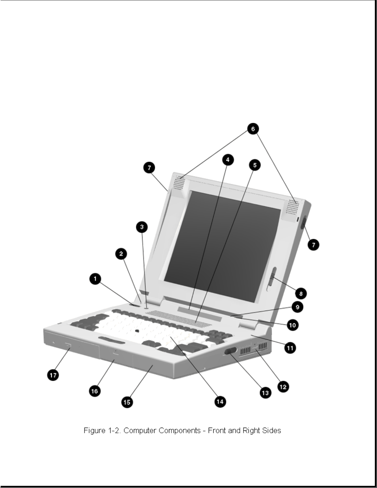
Chapter 1.3 Computer External Components
The external components on the front and right sides of the computer are
shown in Figure 1-2 and are described in Table 1-3.
Table 1-3. Computer Components - Front and Right Sides
Page 13

===========================================================================
Item Component Function
===========================================================================
1 Power switch Turns the power on and off.
--------------------------------------------------------------------------2 Display switch Turns display off and initiates beep if
display is closed with computer on. When
used with the standby button, restarts the
computer.
--------------------------------------------------------------------------3 Standby switch Initiates/exits Standby. When used with
the display switch, restarts the
computer. When used with the Fn key,
initiates Hibernation.
--------------------------------------------------------------------------4 Status panel icons The computer is connected to an external
power source.
QuickLock/QuickBlank has been initiated.
Type the power-on password on the
blank screen to exit
QuickLock/QuickBlank.
Power Management is turned on. Run
Computer Setup to view or change
Power Management settings.
A diskette drive in the MultiBay is
being accessed.
A hard drive in the dedicated hard
drive bay or a hard drive or CD-ROM
drive in the MultiBay is being accessed.
An external monitor is actively
displaying information.
The built-in speakers on the front of the
display or speakers or headphone
connected to the computer or expansion
base are turned on.
Num lock is on, which enables the
embedded numeric keypad.
Caps Lock is on, which causes new text
to be typed in uppercase letters.
Scroll Lock is on, which causes the
cursor to scroll by fields, rather than
by lines.
Battery gauges 1 and 2. Gauge 1 turns on
if a battery pack is in the dedicated
battery bay and shows the amount of
charge in the battery pack. Gauge 2 turns
on if a battery pack is in the MultiBay
and shows the amount of charge in that
battery pack.
Page 14
Page 15

--------------------------------------------------------------------------5 Ventilation intake Intake vents provide proper airflow to
help prevent the computer from
overheating.
--------------------------------------------------------------------------6 Stereo speakers Built-in stereo speakers for PC and
multimedia sound system.
--------------------------------------------------------------------------7 Latch Secures computer in a closed position;
release to open.
--------------------------------------------------------------------------8 Brightness control Adjusts the brightness of the display.
Contrast control (not Adjusts the contrast of the display
shown) (CSTN models).
--------------------------------------------------------------------------9 Standby (suspend) light Illuminates when power to the computer
(green) is turned on. Blinks to indicate
computer is in Standby (Suspend).
---------------------------------------------------------------------------
10 Battery light (yellow) Illuminates when a battery pack is
charging; turns off when the battery
pack is fully charged; blinks to
indicate low battery.
---------------------------------------------------------------------------
11 Microphone Built-in microphone for the Compaq
Sound System.
---------------------------------------------------------------------------
12 PC Card slots Accepts one Type III or two Type II or
two Type I PC Cards (PCMCIA).
---------------------------------------------------------------------------
13 Battery release Releases a battery pack in the battery
compartment.
---------------------------------------------------------------------------
14 Keyboard Keyboard with EasyPoint II pointing
device and pick buttons.
---------------------------------------------------------------------------
15 Battery compartment Dedicated battery compartment for the
main battery pack.
---------------------------------------------------------------------------
16 Hard drive bay Dedicated hard drive bay.
---------------------------------------------------------------------------
17 MultiBay Bay that supports multiple devices:
CD-ROM drive, hard drive, battery pack,
or diskette drive.
===========================================================================
The external components on the rear and left sides of the computer are
shown in Figure 1-3 and described in Table 1-4.
Page 16
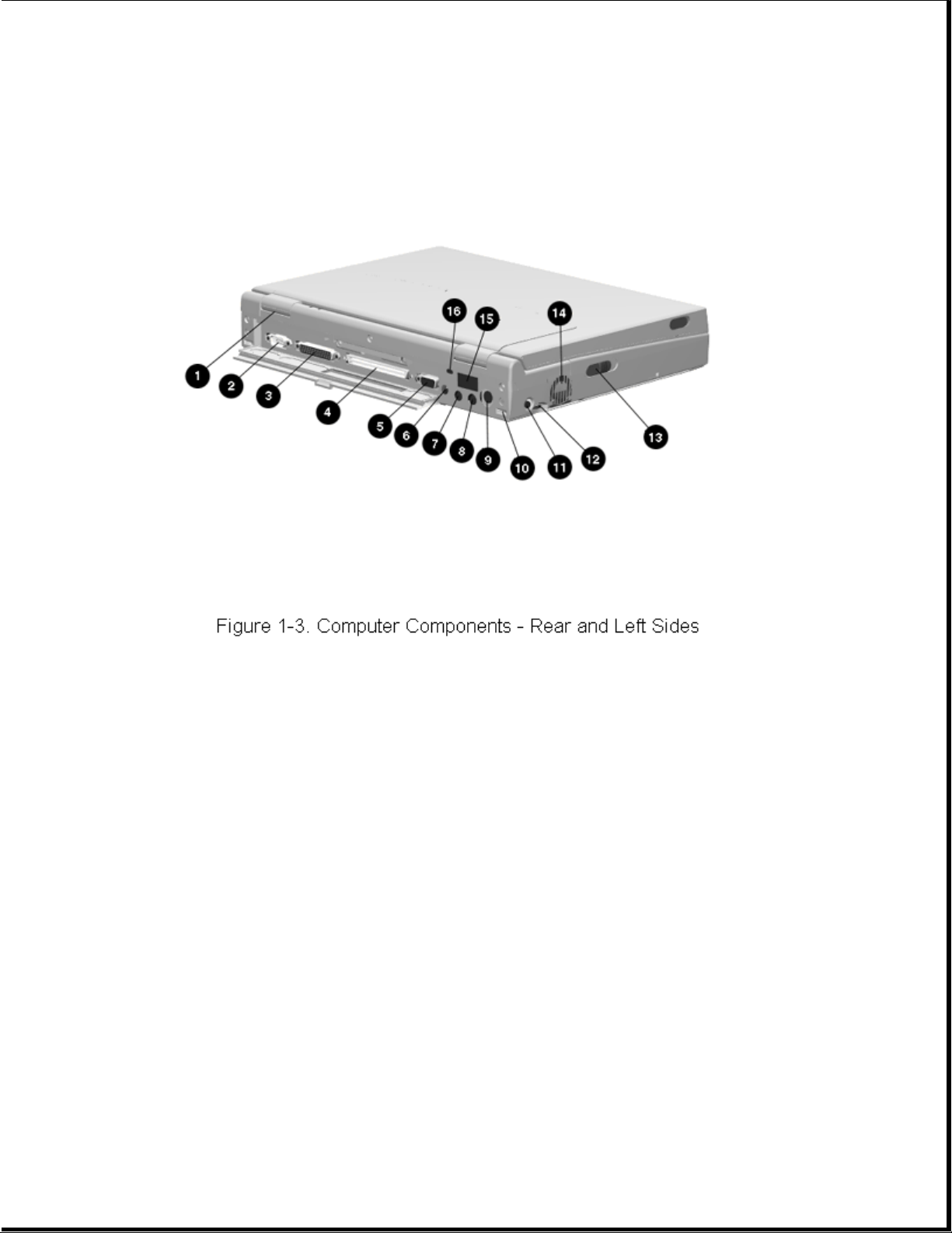
Table 1-4. Computer Components - Rear and Left Sides
===========================================================================
Item Component Function
===========================================================================
1 Serial number Identifies the computer.
--------------------------------------------------------------------------2 Serial connector Connects optional serial devices.
--------------------------------------------------------------------------3 Parallel connector Connects optional parallel devices.
--------------------------------------------------------------------------4 External options Connects the expansion base or the
connector optional Automobile Adapter.
--------------------------------------------------------------------------5 External monitor connector Connects an external monitor.
--------------------------------------------------------------------------6 Power connector Connects the AC Adapter or the
optional Automobile Adapter.
--------------------------------------------------------------------------7 Stereo speaker/headphone Connects external speakers or
jack headphones.
--------------------------------------------------------------------------8 Stereo line in jack Stereo line-in jack for CD player,
tape deck, tuner, or other line level
audio source.
--------------------------------------------------------------------------9 Keyboard/mouse connector Connects an external keyboard, numeric
keypad, PS/2 mouse, or other pointing device.
Page 17

---------------------------------------------------------------------------
10 Docking sensor Access to a microswitch that initiates
the docking scenario when the computer
is being docked. Also serves as a
guide for the MPEG Adapter.
---------------------------------------------------------------------------
11 Mono microphone jack Connects a powered electric condenser
microphone.
---------------------------------------------------------------------------
12 Volume control Controls volume to the built-in
speakers or to external speakers or
headphones connected to the computer
or MultiBay Expansion Base.
---------------------------------------------------------------------------
13 MultiBay device release Releases a drive or battery pack from
the MultiBay.
---------------------------------------------------------------------------
14 Ventilation exhaust Exhaust vent for proper airflow to
help prevent the computer from
overheating.
---------------------------------------------------------------------------
15 Infrared port Transfers data to another computer or
external device that accepts IrDA
format.
---------------------------------------------------------------------------
16 Security slot Provision for an optional security
cable lock to be attached to the
computer.
===========================================================================
Chapter 1.4 Design Overview - Computer
This section presents a design overview of the computer. The discussion is
limited to the field replaceable parts. All replaceable parts are
identified in Chapter 3, and removal/replacement procedures are presented
in Chapter 5.
The computer is a traditional clamshell design with a display unit and
system unit. The computer opens to reveal a backlighted LCD display and
keyboard. The display is designed for a continuously adjustable tilt
angle. The system unit houses the system board, processor board, power
board, keyboard, I/O ports, operator controls and indicators, mass storage
device bays, and battery bay.
The main components of the system unit include the following:
o Processor (Intel Mobile Pentium 75 MHz, 90MHz, 100MHz, 120MHz, 133mhz,
or 150 MHz)
o System controller (OPTi 556/557/558N, OPTi 602A)
o VGA controller (Cirrus CL-GD754x)
o Keyboard controller (Intel 80C51SL)
o PCMCIA controller (Cirrus 6722)
Page 18

o Super I/O (National 87334)
o Audio controller (ESS688 or ESS1688)
o Power controller (47P440AF)
The boards on which these controllers reside are identified in the
sections that follow.
1.4.1 Display Unit
The display unit includes the following field replaceable components:
o Display assembly
o Display bezel with speakers
o Release latches
o Brightness control actuator
o Contrast control actuator (CSTN models only)
o Clutch assemblies
o Compaq logo
Display Assembly
The display assembly is replaced as a complete unit that includes:
o LCD panel
o LCD inverter
o Display bezel
o Stereo speakers
o Clutch assemblies
o Release latches
o Brightness control actuator
o Contrast control actuator (CSTN models only)
NOTE: The display bezel, release latches, brightness/contrast control
actuator(s), Compaq logo, and clutch assemblies can also be replaced
individually. The speakers are permanently installed on the display
bezel.
Page 19

The following LCD panels are supported:
o 10.4-inch (26.4 cm) CSTN VGA Display (640 x 480)
o 11.3-inch (28.7 cm) CSTN SVGA Display (800 x 600)
o 10.4-inch (26.4 cm) CTFT VGA Display (640 x 480)
o 10.4-inch (26.4 cm) CTFT VGA Display (800 x 600)
o 11.3-inch (28.7 cm) CTFT SVGA Display (800 x 600)
o 12.1-inch (30.7 cm) CTFT SVGA (800 x 600)
o 12.1-inch (30.7 cm) CTFT 1024 x 768 Display
Both LCD panels have a controllable backlight intensity that can be
adjusted with a slide switch. The CSTN (dual scan) panels also have a
slide switch for contrast control.
The LCD panel inverter cable plugs into an 8-pin connector on the
processor board. The LCD cable plugs into a connector on the system board.
The inverters and cables differ according to the display type and
manufacturer and cannot be interchanged. All of the display cables are
routed to the system unit in the vicinity of the clutches.
NOTE: It is important that these instructions be followed when replacement
of any part requires removal of the display assembly.
Slide the display assembly back in place and replace all screws. The
screws must be fully tightened to ensure that they do not touch the
expansion base sensor located near the left hinge. Failure to properly
seat the screws may prevent the unit from booting up.
NOTE: Use Fn+F4 hotkeys to switch between external, internal, and
simultaneous display. (The CSTN 800 x 600 does not support
simultaneous display.)
Display Bezel With Speakers
The display bezel attaches to the display unit with a snap action and is
secured with a screw at each corner. Screw covers are installed over the
screw heads. After removing these screws, use a Compaq bezel removal tool
to separate the bezel from the display assembly. The display bezel can be
removed without separating the display unit from the system unit.
The internal stereo speakers are 0.5-watt, 8-ohm, permanently installed in
the top corners of the display bezel and are installed as a unit with
cabling attached. The speaker cable is routed into the system unit and
connects to a 4-pin connector adjacent to the 30-pin LCD connector on the
system board. The CPU cover is easily removed from the system unit to
access this connector.
NOTE: Use Fn+F5 hotkeys to toggle speakers/headphones off and on.
Page 20

Release Latches
The release latches serve to lock the display and system units together
when the computer is in the closed position. Each latch assembly consists
of three parts:
o Latch actuator
o Latch hook
o Latch spring
The release latch assembly is available as a field replaceable unit. The
display bezel must be removed to replace the latch assemblies.
The release latches are mounted in the display unit back cover. The
display bezel must be removed to access the latches. The latches snap into
place and require a simple depression of a tab to be released from the
display cover.
Brightness/Contrast Control Actuator(s)
The displays have a controllable backlight intensity that can be adjusted
with a slide switch. The CSTN panels also have slide switch for contrast
control. The actuators for these adjustments are available as field
replaceable units.
The brightness/contrast control actuator(s) (contrast control actuator on
CSTN displays only) are mounted on the display bezel with a snap action.
The display bezel must be removed to allow the tabs on the back side of
the actuator to be depressed for removal. When installing a display bezel,
make certain the brightness/contrast actuator(s) aligns with the
brightness/contrast control(s) in the display assembly.
Clutch Assemblies
The clutch assemblies provide the hinge function between the display unit
and system unit and also provide continuous tension that allows the
display unit to be positioned at any angle.
The clutch assemblies are available in pairs as field replaceable units.
Each clutch assembly is mounted to the display unit with two screws and to
the system unit with two screws. Removal and replacement of the clutch
assemblies requires removal of the display bezel and the CPU cover (on the
system unit).
Compaq Logo
The Compaq logo is installed on the back of the display unit. The location
for the logo is indicated by an ellipse embossed in the cover. The logo is
an adhesive-backed label that is available as a field replaceable unit.
The label indicates which processor is installed in the computer.
1.4.2 System Unit
Page 21

The system unit contains the following field replaceable units:
o CPU cover
o Internal microphone
o Status panel
o Processor board
o Power board
o Cooling fan
o System board
o Memory expansion board (optional)
o Keyboard assembly
o Auxiliary battery
o Miscellaneous plastic parts
CPU Cover
The CPU cover is located above the keyboard and is secured in place with
three screws on the rear panel of the system unit. Tabs on the front edge
of the CPU cover engage slots across the top edge of the keyboard panel.
The CPU cover contains the actuators for the following:
o Power switch
o Standby (Suspend) button
o Display switch
The CPU cover with all switch actuators installed is available as a field
replaceable unit. The switch actuators are also available as field
replaceable units.
The power switch actuator and spring and the standby (suspend) button
actuator and spring are removed by squeezing the actuator tabs on the
underside of the CPU cover and pushing the buttons out of their mounting
hole. The display switch actuator simply snaps out of its mounting hole
from the underside of the CPU cover.
The CPU cover must be removed to service any of the above described switch
actuators. The cover also must be removed to disconnect any of the display
unit cables from the system unit, to remove the display unit, to service
the status panel, and to remove the keyboard assembly.
Internal Microphone
The internal microphone is supported by the audio subsystem and connects
Page 22

to the system board. It is an omnidirectional condenser microphone with a
standard sensitivity of 40dB. The microphone is mounted in a rubber boot
to provide acoustic isolation and is mounted at the right side of the
keyboard, under the CPU cover.
Status Panel
The status panel is located immediately below the LCD panel on the system
unit. The panel displays a series of icons to indicate system status as
described in Table 1-3.
The status panel also contains two status indicator lights. The right
indicator light provides battery status; the left indicator light provides
power-on and Standby (Suspend) status. Access to the display panel for
service requires removal of the CPU cover. The status display is secured
with two screws. The status panel cable plugs into an 8-pin connector on
the processor board.
Processor Board
The processor board supports the following:
o Processor
o DC-to-DC converter is used only with processors that operate at higher
than 75 MHz.
o L2 cache
o System RAM
o System memory expansion connector
o Power, display, and standby switches
o Infrared serial port (IrDA)
o Display panel configuration jumpers
o Power-on password jumper
The computer supports 75, 90, 100, 120, 133-, and 150-MHz Mobile Pentium
processors. The processor is soldered to the processor board, so
replacement is accomplished by replacing the processor board. A heat sink
on the processor and a cooling fan maintain an operating temperature
within the limits specified by the CPU manufacturer and other components.
All I/O buffers operate at 3.3 volts.The 75-MHz processor core operates at
3.3 volts. The 150-MHz processor core operates at 3.1 volts. The 90-Mhz,
100mhz, 120-MHz, and 133-MHz processor cores operate at 2.9 volts. The 2.9
volts is provided by a DC-to-DC converter mounted on the processor board.
The processors are of a tape carrier package (TCP) design that has a high
pin count, low profile, and reduced footprint. The processor is easily
damaged, so the pins and body of the processor should not be touched.
Page 23

The L2 cache is implemented as direct-mapped, write-back cache with a size
of 256 KB.
The power switch, display switch, and standby (suspend) button are mounted
on the processor board. They are operated by switch actuators mounted on
the CPU cover.
The power switch turns system power on and off. When the switch is pushed
to turn the power off, the system displays a warning message that all
unsaved data will be lost. The shut down process is then completed by
pressing Enter.
The display switch turns the display off and initiates a beep if the
display is closed with the computer on. When used with the standby switch,
the display switch initiates a system restart.
The standby (suspend) button initiates and exits Standby (suspend). As
described above, the standby button, when used with the display switch,
initiates a system restart. When used with the Fn key, the standby button
initiates Hibernation.
The processor board contains 8 MB or 16 MB of onboard memory and can be
expanded to 72 or 80 MB by adding a 64 MB memory expansion board. The
memory expansion boards are available in 8, 16, 32, and 64 MB DRAM
configurations. Each module is composed of two boards assembled together.
The system ROM is shadowed in system memory.
The infrared subsystem (IrDA) provides two-way wireless communication
using infrared as a transmission medium. Proper operation requires the
communicating infrared ports to be within a 30-degree path and no more
than three feet (1 meter) apart.
The processor board must be configured according to the display type. This
is done by setting Jumpers JP2, JP3, and JP4 on the processor board. Use
Table 1-5 to determine proper jumper settings for the display.
Table 1-5. Display Configuration Jumpers
===========================================================================
Display Type Jumper JP3 Jumper JP2 Jumper JP4
===========================================================================
LTE 5000 10.4 in VGA CSTN 1-2 2-3 1-2
LTE 5000 10.4 in VGA CTFT 2-3 2-3 1-2
LTE 5000 11.3 in SVGA CSTN 1-2 2-3 2-3
LTE 5100 10.4 in SVGA CTFT 2-3 2-3 2-3
LTE 5200 10.4 in SVGA CTFT 2-3 2-3 2-3
LTE 5280 11.3 in SVGA CTFT 2-3 2-3 2-3
LTE 5300 12.1 in SVGA CTFT 2-3 2-3 2-3
LTE 5150 Rev. 4X 11.3 in
SVGA CSTN 1-2 1-2 1-2
LTE 5150 Rev. 2X SVGA CSTN 2-3 1-2 1-2
Page 24

LTE 5250 10.4 in SVGA CTFT 2-3 2-3 2-3
LTE 5380 12.1 in 1024 x 768
CTFT 2-3 1-2 1-2
LTE 5400 12.1 in 1024 x 768
CTFT 2-3 2-3 2-3
===========================================================================
The power-on password jumper is also located on the processor board. To
erase the power-on password, set jumper JP1 to pins 1 and 2; set JP1 to
pins 2 and 3 for normal operation. See Chapter 2 for more details.
To remove and replace the processor board, you must first remove the CPU
cover, EMI shield, keyboard, and display unit. The processor board is
secured in place with two screws and is connected to the system board with
two connectors.
System Board
There are three system boards for the computer: one to support the 75 MHz,
90 MHz and 120 MHz processors (LTE 5000, LTE 5100, and LTE 5200); one to
support the 120 MHz, 100MHz, and 133 MHz processors (LTE 5280, LTE 5300,
LTE 5150, and LTE 5250); and one to support the 133 MHz processor (LTE
5380) and 150MHz processor (LTE 5400). The system board supports the
following:
o System ROM (BIOS)
o Graphics subsystem
o Audio subsystem
o PC Card subsystem
o Diskette drive controller
o RS-232 and IrDA serial ports
o IDE interface
o Fan connector
o I/O connectors
The firmware components for the computer include:
o System BIOS for the OPTi Viper Notebook chip set
o ROM-based setup
o MAXIMIZER Power Management for OPTi Viper
o APM 1.1 BIOS
o Plug and Play BIOS
Page 25

o PCI BIOS
o Keyboard Controller Firmware for the Intel 80C51SL
o VGA BIOS
The ROM-based setup has been translated into ten languages in addition to
English. Messages that are displayed by the BIOS which require no user
interaction are displayed in English. This includes POST warning messages,
error messages, and runtime warnings and notifications. Messages that are
displayed by the BIOS which require user interaction are translated into
the same language as Setup.
The graphics controller interfaces with the system through the PCI bus.
The controller provides backward compatible modes to support CGA, EGA,
MGA, and HGA as well as all current VGA and SVGA modes. The controller
supports the internal LCD panels as well as an external CRT and
simultaneously supports the LCD and CRT (except for models with the
11.3-in CSTN SVGA display). The CRT interface is also routed to the either
expansion base through the external options connector. For LCD only and
LCD/CRT simultaneous display modes, the following panel and color
resolutions are supported:
Table 1-6. Maximum Resolutions Supported
===========================================================================
Display Type Display Modes Color Depth Supported
===========================================================================
640 x 480 CTFT 640 x 480 256, 64K, 16M
800 x 600 CTFT 640 x 480, 800 x 600 256, 64K
640 x 480 CSTN 640 x 480 256, 64K
800 x 600 CSTN 640 x 480, 800 x 600 256
1024 x 768 CTFT 1024 x 768 256
===========================================================================
The graphics controller also supports display of real-time video from the
MPEG and TV Video Adapter at a rate of 30 frames per second (fps). It
provides the capability to overlay the video in a Windows screen.
The computer has 1 MB of video DRAM soldered to the system board. There
is no provision for adding additional video memory.
The graphics subsystem is designed to minimize the use of power at all
times. When the system is idle for a set period of time, the controller is
placed in the lowest power state. The LCD panel backlight and panel power
are turned off during periods of inactivity after a timeout as determined
by the user in Computer Setup. The system supports Energy Star monitors
and allows the feature to be turned on/off from Computer Setup.
The computer supports an interface to an MPEG and TV Video Adapter that
attaches to the rear of the computer. The adapter provides up to 30 fps of
live video or MPEG video to the graphics controller for display on the
LCD, a CRT, or a television. The MPEG and TV Video Adapter and CD-ROM
Page 26

drive can be used simultaneously.
The audio subsystem is integrated into the system board. The system
supports an internal microphone, stereo speakers, SoundBlaster PRO
compatible audio, CD-ROM audio inputs, an external jack for headphones or
speakers, microphone jack, and line-input jack. Line and CD-ROM inputs and
the speaker outputs are passed through the external options connector and
supported by both expansion bases.
The internal speakers are disabled when the computer is docked in the
expansion base and when headphones or external speakers are installed.
The heart of the audio subsystem is the ESS1688 (ESS688 on Windows 3.1/Dos
6 units) AudioDrive ASIC that provides 16-bit stereo WAV audio, audio
mixing, and FM music synthesis. The entire audio system connects directly
to the ISA bus.
The ESS1688 is OPL3 compatible and compatible with SoundBlaster PRO and
Microsoft Windows Sound System. It can record, compress, and play back
sound and music at 8 or 16 bits up to 44 Khz.
The computer has one PC Card (PCMCIA) controller that supports a Type III
PC card slot that supports either two Type II PC Cards or one Type III PC
Card. A PC card door prevents contamination of the slot. The controller is
Intel ExCA compatible and complies with the Berlin revision of the PCMCIA
standard. The controller supports 5-V cards and all current Compaq PC
Cards. A second PC Card controller is located in both expansion bases.
The diskette drive controller supports 720K, 1.2 MB, and 1.44 MB densities
as well as automatic media detection. Diskette drives can be used in the
computer MultiBay and the expansion bases. When using Windows 95, real
mode drivers must be used for a diskette drive in the expansion base. For
more information see "Solving Diskette and Diskette Drive Problems" in
Chapter 2.
The PC87334 Super I/O contains two UARTs which are fully compatible with
NS15450 and NS16550. Both ports support MIDI baud rates and one port also
supports IrDA and HP SIR compliant signaling protocol. The two serial
ports are configured as one RS- 232C serial port and one infrared (IrDA)
port.
o The standard RS-232 serial port has an 82550 compatible serial
controller. The physical connector is a standard 9-pin D connector. The
interface can be configured as COM1, COM2, COM3, or COM4.
o The infrared communication is implemented with an 82550 compatible
serial controller. The minimum data rate supported by the Infrared Port
is 115K bits per seconds. The interface can be configured as COM1, COM2,
COM3, or COM4.
The parallel port support is integrated into the PC87334 Super I/O. The
computer has one parallel port that can be configured to operate in
compatible mode, enhanced modes 1.7 and 1.9 (EPP), and extended
capabilities (ECP) mode (IEEE-1284 compatible). The default mode is the
compatible mode. The physical connector is a standard 25-pin D connector.
The parallel port interface can be configured as LPT1, LPT2, or LPT3.
When the computer is mounted in either expansion base, the system can
Page 27

support up to four IDE hard drives. When using two hard drives in the
computer, one of the hard drives is installed in the dedicated hard drive
bay and the other in the MultiBay.
NOTE: The dedicated hard drive bay provides limited support for the Compaq
LTE Elite hard drive. See Appendix C for details.
The hard drive remains powered off from Standby (Suspend) until the first
access occurs. The hard drive is powered off during Standby (Suspend).
The cooling fan is mounted in the system unit on the left side at the
ventilation exhaust port. Functioning as an exhaust fan, it provides air
flow across the electronic components for cooling. The fan plugs into a
2-pin connector on the system board.
The I/O connector panel is an integral part of the system board. In
addition to the I/O panel, the system board supports the following:
o PC card rails and connectors
o Battery bay contacts
o Hard drive bay connector
o MultiBay mass storage device connector
o MultiBay battery contacts
o Power board connectors
o Processor board connectors
o Fan connector
o LCD panel connector
o Speaker connector
o Integrated microphone connector
o External microphone connector
o Volume control
The CPU cover, display unit, keyboard, processor board, and power board
must be removed prior to removing the system board. The system board is
secured with two screwlocks on the I/O connector panel, a standoff in the
left rear corner, and three screws.
IMPORTANT: Correct positioning of the system board is essential for proper
interconnect of the computer with either expansion base. When
installing a system board, be sure the locating pins near the
mounting screws properly engage the system board.
Page 28

A connector on the rear of the computer interfaces with either expansion
base to provide additional functionality. The expansion base replicates
the following computer connectors:
o Serial connector
o Parallel connector
o External monitor connector
o PS/2-compatible mouse connector
o Power connector
o External keyboard connector
o All audio connectors except mono microphone jack
Additional MultiBay Expansion Base and MultiBay ISA details are presented
in Section 1.5.
Power Board
The power board is a DC-to-DC converter that provides the required
voltages of +3.3 and +5 volts from one of the power sources (main battery
pack, AC Adapter, or Automobile Adapter).
The power board is provided as a field replaceable unit. To remove and
replace the power board, you must first remove the CPU cover, keyboard,
and processor board. The power board connects to the system board with two
connectors and is secured in place with one screw.
Keyboard
The keyboard is available as an assembly consisting of the following
parts:
o Keyboard
o Keyboard bezel
o Battery release
o MultiBay device release
o EasyPoint II controller
The battery release, MultiBay device release, and EasyPoint II controller
are also available as replaceable units.
To remove the keyboard assembly, the CPU cover must be removed first. The
keyboard ribbon cable (ZIF connector) and EasyPoint II controller cable
must be disconnected. Three screws on the bottom on the system unit and
four screws across the front (inside of the MultiBay and dedicated battery
compartment) must then be removed to release the keyboard.
Page 29

The battery release mechanism consists of the following parts:
o Battery release actuator
o Battery release spring
o Battery release holder
o Battery release hook
o Battery release hook spring
All of these components are included in the Latches Kit.
The battery release spring maintains the mechanism in the latched state
until the release actuator is pushed. This action retracts the release
hook from the battery. The release hook spring ensures that the battery
hook firmly engages the battery. The battery release holder serves as a
mounting platform for the other release mechanism components. The release
hook and release hook spring are fastened to the release holder with a
screw. The release spring connects the release actuator to the holder. The
holder is held to the bottom of the keyboard with two screws.
The MultiBay device release mechanism is very similar to the battery
release mechanism and consists of the following parts:
o MultiBay device release actuator
o MultiBay release spring
o MultiBay release holder
o MultiBay release hook
o MultiBay release hook spring
o CD-ROM drive release bar
All of these components are included in the Latches Kit.
The MultiBay device release spring maintains the mechanism in the latched
state until the release actuator is pushed. This action retracts the
release hook from the diskette drive or hard drive. Pushing the release
actuator also causes the CD-ROM drive release bar to eject a CD-ROM drive
if one is installed. The release hook spring ensures that the release hook
firmly engages the device in the MultiBay. The MultiBay release holder
serves as a mounting platform for the other release mechanism components.
The release hook and release hook spring are fastened to the release
holder with a screw. The release spring connects the release actuator to
the holder. The holder is held to the bottom of the keyboard with a screw
and standoff.
The EasyPoint II controller supports the mouse buttons and the EasyPoint
II pointing stick. It is mounted to the bottom of the keyboard assembly
directly under the mouse buttons. The CPU cover and keyboard must be
removed to gain access to the controller. Two screws hold the controller
Page 30

to the keyboard. Once released, the flat cable can be disconnected from
the ZIF connector on the underside of the controller.
MultiBay
The MultiBay accommodates the following devices:
o Dual-speed, quad-speed, or 6x CD-ROM drive
o Second hard drive
o Second battery pack
o 3.5-inch diskette drive
NOTE: The hard drive must be mounted in the MultiBay hard drive carrier
before it can be installed into the MultiBay.
The computer must be turned off when inserting a drive (not the battery
pack) or removing it from the MultiBay.
Chapter 1.5 Optional MultiBay Expansion Base and MultiBay ISA Expansion Base Features
The MultiBay Expansion Base and MultiBay ISA Expansion Base provide fully
integrated desktop capabilities for the computer. The expansion base
eliminates the need to disconnect external devices when you remove the
computer from the expansion base. The optional expansion base has the
following features:
o Two MultiBay device bays
o One serial port
o One parallel port
o PS/2 mouse port
o External keyboard port
o One SVGA CRT port
o Ethernet RJ-45 and BNC ports
o Two Type III PC Card slots
o Audio line out, headphones out
o Audio line in
o IR interface for IrDA wireless operations
o Battery charge indicators
o Drive activity indicators
Page 31

o Security features
o Stereo speakers
o ISA expansion slot (MultiBay ISA Expansion Base)
o High performance stereo speakers and new audio bass ports on both sides
of the expansion base for Compaq PremierSound audio system (MultiBay ISA
Expansion Base)
Chapter 1.6 MultiBay Expansion Base and MultiBay ISA Expansion Base Components
The external components on the front and right sides of the expansion base
are shown in Figure 1-4 and described in Table 1-7.
Table 1-7. Expansion Base Components - Front and Right Sides
===========================================================================
Item Description
===========================================================================
1 Monitor support cover slots
2 External options connector
3 Stereo speakers (MultiBay Expansion Base model)
Page 32

4 MultiBay II device release button
5 MultiBay II
6 PC Card release buttons
7 Ventilation exhausts (MultiBay ISA Expansion Base model)
8 PC Card slots
9 ISA slot access door (MultiBay ISA Expansion Base model)
10 Stereo speaker (MultiBay ISA Expansion Base model)
11 Security cable slot
12 Docking lever
13 Audio bass port (MultiBay ISA Expansion Base model)
14 Battery lights
15 Docking aid
===========================================================================
Additional components on the front of the expansion base and the
components on the left side of the expansion base are shown in Figure 1-5
and described in Table 1-8.
Page 33

Table 1-8. Expansion Base Components - Front and Left Sides
===========================================================================
Item Description
===========================================================================
1 MultiBay I device release button
2 MultiBay I
3 Docking sensor probe
4 Stereo speakers (MultiBay Expansion Base model)
5 Alignment guide
6 Power light
7 Power button
8 Infrared port
9 MultiBay drive lights
10 Audio bass port (MultiBay ISA Expansion Base model)
11 Stereo speaker (MultiBay ISA Expansion Base model)
12 Ventilation exhaust (MultiBay ISA Expansion Base model)
Page 34

13 AC power connector
===========================================================================
The external components on the rear panel of the expansion base are shown
in Figure 1-6 and described in Table 1-9.
Table 1-9. Expansion Base Components - Rear Panel
===========================================================================
Item Description
===========================================================================
1 External mouse connector
2 External keyboard connector
3 Stereo speaker/headphone jack
4 Stereo line in jack
5 Ethernet RJ-45 connector
6 Ethernet BNC connector
7 MIDI/Game connector
8 External monitor connector
Page 35

9 Parallel connector
10 Serial connector
11 Auxiliary fan (MultiBay ISA Expansion Base model)
12 MPEG and TV Video Adapter connector
13 ISA slot cover (MultiBay ISA Expansion Base model)
===========================================================================
Chapter 1.7 Design Overview - MultiBay Expansion Base and MultiBay ISA Expansion Base
In addition to replicating the computer I/O panel and offering additional
mass storage device bays, the expansion bases include the following:
o Main board with integrated Ethernet
o MultiBay connector board
o Power supply
o IrDA interface
o Activity lights
o MultiBays with ejectors
o PC Card slots
o ISA expansion board slot (MultiBay ISA Expansion Base model)
o Computer docking mechanism
1.7.1 Main Board
The expansion base main board supports the following major components:
o Ethernet controller (National DP83907)
o PCMCIA controller (Cirrus 6722)
o Super I/O (National 87334)
o Power controller (TMP47P440AF)
The Ethernet controller supports an integrated 10MB/sec Ethernet
subsystem with 10BaseT and 10Base2 interfaces. The Super I/O component
supports the MultiBays.
1.7.2 MultiBay Connector Board
Page 36

The MultiBay connector board is mounted between the two MultiBays and
serves to route the appropriate signals to the MultiBay connectors.
1.7.3 Power Supply
The power supply is an AC-to-DC converter that serves the same function as
the AC adapter and DC-to-DC converter in the computer. It provides
regulated DC power for all of the subsystems. The expansion base uses a
standard AC power cord that connects directly to the power supply.
An external fan mounted on the power supply provides cooling. When the
temperature of the power supply exceeds 104oF (40oC), the fan turns on.
When the temperature drops below 104oF, the fan turns off.
The MultiBay ISA model has an auxiliary cooling fan mounted on the rear of
the bottom case. The auxiliary fan remains active as long as power is
applied to the MultiBay ISA Expansion Base.
1.7.4 IrDA Interface
The IrDA interface is mounted on the front left corner of the expansion
base and shares a small PCB with the removable drive status lights. The
board is mounted to the underside of the expansion base top cover with a
single screw. The IrDA interface on the expansion base replicates the IrDA
interface on the computer.
1.7.5 Activity Lights
The expansion base has two sets of activity lights.
Removable-Drive Lights
The removable-drive lights are installed on the front left of the
expansion base and share a small PCB with the IrDA interface. The board is
installed as a unit from the back side of the expansion base top cover.
The status lights are identified in Figure 1-7 and described in Table
1-10.
Page 37

Table 1-10. Removable Drive Lights
===========================================================================
Index Function Description
===========================================================================
1 Computer diskette drive light Diskette drive in computer MultiBay
is being accessed
2 Computer hard drive/CD-ROM Hard drive or CD-ROM drive in
drive light computer is being accessed
3 MultiBay hard drive/CD-ROM Hard drive or CD-ROM in one of the
drive light expansion base MultiBays is being
accessed.
4 MultiBay diskette drive light Diskette drive in one of the
expansion base MultiBays is being
accessed
===========================================================================
Battery Lights
The battery lights are installed on the front right of the expansion base
and share a small PCB with the power button and power light. The board is
installed as a unit from the back side of the expansion base top cover.
The battery lights are identified in Figure 1-8 and described in Table
1-11.
Page 38

Table 1-11. Battery Lights
===========================================================================
Index Function Description
===========================================================================
1 Computer MultiBay battery Status of battery pack in computer
light MultiBay
2 Computer battery light Status of battery pack in computer
battery compartment
3 MultiBay II battery light Status of battery in MultiBay on
the right side of the expansion
base
4 MultiBay I battery light Status of battery in MultiBay on
the left side of the expansion
base
===========================================================================
1.7.6 MultiBays with Ejectors
Each expansion base has two MultiBays. Each MultiBay is removable as a
unit with its ejector mechanism. The MultiBay is held to the expansion
base cover with three screws. The MultiBays in the expansion base
accommodate the same drives that are used by the computer and can be used
Page 39

to charge batteries. MultiBay I will accept Compaq LTE Elite hard drives.
1.7.7 PC Card Slots
Each expansion base has two Type III PC Card slots that function similarly
to the PC card slots on the computer. Each PC Card slot on the expansion
base supports one Type I, one Type II, or one Type III PC Card. The only
serviceable part of the PC card slots are the slot doors. The rails and
connectors are incorporated into the main board.
1.7.8 Computer Docking Mechanism
The computer docking mechanism has a lever that protrudes from the right
side of either expansion base and serves to aid in seating the computer
when it is pushed toward the rear of the expansion base. The lever
releases the computer from the expansion base when it is pushed toward the
front of the expansion base.
1.7.9 ISA Expansion Board
The MultiBay ISA Expansion Base provides one slot for an 8- or 16-bit,
full-length industry-standard (ISA) expansion board.
The following provisions must be considered when choosing the type of ISA
expansion board to be installed in the expansion base:
o The enhanced video performance of the Compaq LTE 5000 Family of Personal
Computers drives an external monitor at resolutions up to 1024 x 768 x
256 colors and at selectable refresh rates up to 72 Hz, making the use
of ISA graphics controller boards unnecessary. If an ISA graphics
controller card is installed, the system will not operate. Graphics
controller boards are not supported.
o If a National NE2000 or compatible network ISA board is installed, the
built-in ethernet connectors in the expansion base are disabled. To
re-enable the built-in ethernet network feature, the NE2000 or
compatible network ISA expansion board must be removed.
Two Network Interface Cards (NICs) can be enabled at one time as long as
both are not NE2000 or compatible.
NOTE: NICs that have a default address of 300h require setup
configuration changes because the built-in ethernet uses the 300h
address.
o Some Moving Picture Experts Group (MPEG) ISA boards cannot be installed
as they require connection to the "feature connector" of the graphics
controller. This feature connector is not provided on the MultiBay ISA
Expansion Base. MPEG ISA boards with a standard video port (external
monitor connector) that do not require connection to the feature
connector on the graphics controller should function satisfactorily.
Page 40

The Compaq MPEG and TV Video Adapter option provides enhanced MPEG
capabilities for use with the Compaq LTE 5000 Family of Personal
Computers. To achieve maximum MPEG functionality support, use the Compaq
MPEG and TV Video Adapter option.
o Due to the vast numbers of ISA expansion boards that are available,
Compaq does not guarantee or support every ISA expansion board.
Refer to the documentation accompanying the ISA expansion board being
installed for complete installation and configuration instructions.
Page 41

Chapter 2. Troubleshooting
Chapter 2.0 Introduction
This chapter contains troubleshooting information for the computer. The
basic steps in troubleshooting include:
1. Completing the preliminary steps listed in Section 2.1.
2. Running the Power-On Self-Test (POST) as described in Section 2.4.
3. Running the Computer Checkup (TEST) as described in Section 2.5.
4. Performing the recommended actions described in the diagnostic tables
in Section 2.7 if you are unable to exercise POST or Computer Checkup
or if the problem persists after running POST and Computer Checkup.
Adhere to the following guidelines when troubleshooting:
o Complete the recommended actions in the order in which they are given.
o Repeat POST and Computer Checkup after each recommended action until the
problem is resolved and the error message does not return.
o Once the problem is resolved, do not complete the remaining recommended
actions.
o Refer to Chapter 5 for any removal and replacement procedures that are
recommended.
Chapter 2.1 Preliminary Steps
IMPORTANT: Use the AC adapter when running POST, Computer Setup, or
Computer Checkup. A low battery condition could initiate
Standby (Suspend) and interrupt the test.
Before running POST and Computer Checkup, complete the following steps:
1. If a power-on password has been established, type the password and
press Enter.
NOTE: The key icon appears on the status display when the computer is
turned on to indicate that QuickLock/QuickBlank has been initiated.
Type the power-on password to exit QuickLock/QuickBlank. If the
password is unknown, it must be cleared (see Section 2.2).
2. Run Computer Setup (Section 2.3).
3. Position the brightness control actuator and contrast control actuator
(on selected models) in the center of their ranges and leave the
Page 42

display open.
4. Turn off the computer and all external devices.
5. Disconnect any external devices that you do not want to test. If you
want to use the printer to log error messages, leave it connected to
the computer.
NOTE: If a problem only occurs when an external device is connected to the
computer, the problem could be with the external device or its
cable. Isolate the problem by running POST with and without the
external device connected.
6. Use Advanced Diagnostics and loopback plugs in the serial and parallel
connectors if you plan to test these ports. To run Advanced
Diagnostics, complete the following steps:
a. Insert the Diagnostics diskette into the diskette drive and turn on
the computer.
b. At the Welcome Screen, press Ctrl + A.
c. Press Enter to accept OK.
d. Select Computer Checkup (TEST).
e. Select Prompted Diagnostics after "Identifying System Hardware"
completes.
f. Select Interactive Testing and follow the displayed instructions.
Refer to Chapter 3 for description and spare part number for the loopback
plugs.
7. Ensure that the primary hard drive is installed in the computer.
8. Ensure that the battery pack is installed in the computer and the AC
Adapter is connected to the computer and plugged into an AC power
source.
After completing the preliminary steps, run POST (Section 2.4) and
Computer Checkup (Section 2.5).
Chapter 2.2 Clearing the Power-On and Setup Passwords
The power-on password prevents use of the computer until the password is
entered. The setup password prevents unauthorized changes to Computer
Setup. To clear the passwords, you must remove and replace a jumper on the
system board. If you do not know the passwords, use the following
procedure to clear the password:
1. Complete the preparation for disassembly procedures in Section 5.3.
2. Remove the CPU cover as described in Section 5.5.
Page 43

3. Move the jumper on JP1 (Figure 2-1) from pins 2 and 3 to pins 1 and 2.
4. Turn on the computer and run POST.
5. Turn off the computer and move the JP1 jumper to pins 2 and 3 for
normal operation.
Chapter 2.3 Running Computer Setup
The ROM-based Computer Setup displays the current system configuration and
allows you to set system and power management parameters. These parameters
are stored in CMOS, and a backup copy is saved in a parameter block in
system flash ROM.
You can access Computer Setup by pressing F10 when the prompt appears
after you turn on or restart the computer. The following configuration
parameters can be changed in Computer Setup:
o Date and time
o Power conservation (when)
Page 44

o Power conservation (level)
o PC Card slot power management
o Hibernation on/off
o Hibernation settings
o Warning beep
o Setup password
o Diskette drive disable
o Serial/IrDA ports disable
o Parallel port disable
o PC Card slots disable
o Resume password on/off
o Boot memory test
o Keyboard numlock
o Boot sequence
o Boot display
o Serial port settings
o Infrared port settings
o Parallel port settings
o Power-on password
o Diskette drive boot disable
o NTSC/PAL
o Windows 95 Power Properties
o Lid closure notification
o Advanced LPT mode
Computer Setup automatically recognizes and configures the system for new
Compaq devices. It does this without prompting you for information about
the devices. However, if you add a memory expansion board, the next time
you turn on the computer a prompt appears notifying you of the new memory
configuration.
The first Computer Setup screen displays current settings for the system,
ports, and devices. The status bar at the bottom of the screen gives
instructions for navigating and choosing options. The status bar also
displays descriptions as you highlight menus and menu options.
Page 45

NOTE: If the main system board is replaced, the serial number on this
screen changes to 0 (zero).
Select one of the menus from the menu bar at the top of the screen to view
or to change the following configuration settings:
o Initialization startup preferences
o Ports, including serial/infrared, parallel, Ethernet, and MPEG
o Power, including Power Management and Hibernation
o Security, including setup and power-on passwords and disabling devices
2.3.1 Initialization Menu
Select the Initialization menu to set the date and time and to change the
initialization (startup) settings for running the POST memory tests,
numlock on or off, the drive boot sequence, boot display, and lid closure
notification.
NOTE: The boot sequence sets the order in which the system searches for a
bootable drive to start the computer. Before changing the booting
sequence, see "The Hard Drive Boot Sequence" in Appendix C for more
information.
2.3.2 Ports Menu
Select the Ports menu to change the default input/output (I/O) addresses
and interrupt requests (IRQs) for serial/infrared, parallel, and Ethernet
ports, select PAL or NTSC for the optional MPEG video format, and enable
Advanced LPT mode.
NOTE: If you select conflicting settings for the ports, the system
automatically changes one of the settings.
2.3.3 Power Menu
Select the Power menu to enable or disable Power Management, PC Card slot
power management (not available on LTE 5000, LTE 5100, and LTE 5200
models), low-battery warning beeps, and an external energy saving monitor.
The factory default settings are:
o Power Management Enabled While on Battery
o Conservation Level Medium
o Low-Battery Warning Beeps Enabled
o External Energy Saving Monitor Disabled
Page 46

o PC Card Power Off During Standby
>>>>>>>>>>>>>>>>>>>>>>>>>>>>>>>>> CAUTION <<<<<<<<<<<<<<<<<<<<<<<<<<<<<<<<<
If you disable Power Management or Hibernation, you must take immediate
action to resolve a low-battery condition to prevent losing unsaved
information.
>>>>>>>>>>>>>>>>>>>>>>>>>>>>>>>>>>>>><<<<<<<<<<<<<<<<<<<<<<<<<<<<<<<<<<<<<<
If you select to disable the low-battery warning beeps, a low-battery
condition is indicated only by a blinking battery light. If you disable
Power Management or Hibernation, information in memory is not
automatically saved during a critical low-battery condition.
If you enable the selection for an external energy saving monitor, it
enters low-power mode when the screen timeout occurs. If you enable this
selection and you do not have an energy saving monitor, the screen display
may become distorted.
Under PC Card slot power management, resume power to the PC Card slots and
ring reserve feature may be enabled during Standby (Suspend). This feature
is not available on the LTE 5000, LTE 5100, and LTE 5200 models.
Under Power Management, you can select whether to enable Power Management
while on AC or battery power, only while on battery power, or never
(disabled).
If you enable Power Management, you can select the conservation level:
high, medium, or custom. The conservation level sets the timeouts for
Standby (Suspend), Hibernation, drives, and screens.
A timeout is a period of inactivity after which power is turned off to the
system or component. Refer to Chapter 7 for more information about Standby
(Suspend) and Hibernation.
o High: - Provides the maximum amount of power conservation and the
maximum battery operating time from a single charge.
o Medium (default): - Provides a balance between performance and battery
life.
o Custom: - Conserves power according to specified timeout settings.
NOTE: Selecting to disable the infrared port under the Security menu also
conserves power.
Windows 95 Power Properties
To open the Windows 95 Power Properties dialog box, double click the Power
icon in Control Panel. Windows 95 provides the following options:
o Advanced (default) - Activates power management settings in Computer
Setup and provides some additional power-saving features.
o Standard - Activates the settings in Computer Setup.
Page 47

o Off - Turns off all power management. The power management icon on the
status panel turns off.
NOTE: You can also temporarily toggle power management off and on by
pressing the Fn+F7 hotkeys. The next time you restart the computer,
the Power Properties setting takes effect.
2.3.4 Security Menu
Select the Security menu to set, change, or delete the setup and power-on
passwords, and to enable/disable QuickLock/QuickBlank, power-on password
from Standby, diskette drives, ports, and PC Card slots.
Setup Password
Use the Setup password to protect the system configuration from
unauthorized changes. After you establish the setup password, you cannot
change the system configuration until you enter the setup password.
IMPORTANT: Type carefully because the password does not display as you
type it. If you choose to, you can use the same password for
setup and for power-on.
The next time you press F10 (after POST) to run Computer Setup, a password
prompt appears on the screen. If you enter the password incorrectly, you
are prompted to reenter the password.
If you forget your setup password, you cannot change the system
configuration until the computer memory is cleared of the password.
>>>>>>>>>>>>>>>>>>>>>>>>>>>>>>>>> CAUTION <<<<<<<<<<<<<<<<<<<<<<<<<<<<<<<<<
Record your setup password and put it in a safe place. If you forget your
setup password, you cannot reconfigure the computer until the computer
memory is cleared of the password.
>>>>>>>>>>>>>>>>>>>>>>>>>>>>>>>>>>>>><<<<<<<<<<<<<<<<<<<<<<<<<<<<<<<<<<<<<<
Power-On Password
The power-on password prevents use of the computer until the password is
entered. After you establish the power-on password, you must enter it
whenever you turn on the computer.
IMPORTANT: Type carefully because the password does not display as you
type it. If you choose to, you can use the same password for
setup and for power-on.
You can also select to require the power-on password when exiting Standby
(Suspend).
The next time you start the computer or exit Standby (Suspend), a password
prompt appears. If you enter the password incorrectly, you are prompted to
reenter the password.
Page 48

If you forget your power-on password, you cannot use the computer until
the computer memory is cleared of the password.
>>>>>>>>>>>>>>>>>>>>>>>>>>>>>>>>> CAUTION <<<<<<<<<<<<<<<<<<<<<<<<<<<<<<<<<
Record your power-on password and put it in a safe place. If you forget
your power-on password, you cannot use the computer until the computer
memory is cleared of the password.
>>>>>>>>>>>>>>>>>>>>>>>>>>>>>>>>>>>>><<<<<<<<<<<<<<<<<<<<<<<<<<<<<<<<<<<<<<
QuickLock/QuickBlank
Enabling QuickLock/QuickBlank allows you to temporarily disable the
keyboard and clear the screen until the power-on password is entered.
After you have enabled QuickLock/QuickBlank, you can initiate it at any
time by pressing the Fn+F6 hotkeys.
When QuickLock/QuickBlank is initiated, the key icon on the status panel
turns on. Type your power-on password on the blank screen to exit
QuickLock/QuickBlank.
Disabling Devices
The Security Menu provides a way to disable the following devices:
o Serial and infrared ports
o Parallel port
o PC Card slots
o Diskette drive
Disabling these devices prevents the unauthorized transfer of data using
the devices. Disabling the infrared port also conserves power. To reenable
a device, deselect the Disable option and restart the computer.
2.3.5 Exit Menu
The Exit menu has three options:
o Save and Exit: Saves configuration changes, but some changes do not take
effect until the computer is restarted.
o Exit (No Save): Exits and does not save the changes you have made.
o Restore Factory Defaults: Replaces the current configuration settings
with the original factory default settings.
Chapter 2.4 POST Error Messages
Page 49

This chapter contains typical error messages that you may encounter during
the power-on self-test (POST). POST is a series of tests that run every
time you turn on the computer. POST verifies that the system is configured
and functioning properly. A successful POST is followed by one or two
short beeps.
If you receive an error message listed below, follow the recommended
action. If you receive an error message that is not listed, contact your
Compaq authorized service provider. You may also want to run Computer
Checkup from the Diagnostics diskette. Information about running Computer
Checkup is presented later in this section.
If POST detects an error, one of the following events occurs:
o A message with the prefix "WARNING" appears informing you where the
error occurred. The system pauses until you press F1 to continue.
o A message with the prefix "FATAL" appears informing you where the error
occurred. After the message, the system emits a series of audible beeps.
The system then stops.
o The system emits a series of audible beeps. The system then stops.
Warning messages indicate a potential problem exists such as a system
configuration error. When F1 is pressed, the system should resume. You
should be able to correct problems that produce WARNING messages.
IMPORTANT: When a WARNING message includes the prompt to "RUN SCU," run
Computer Setup. (Computer Setup replaces the SCU utility.)
Fatal errors emit a beep and may display a FATAL message. Fatal errors
indicate severe problems, such as a hardware failure. Fatal errors do not
allow the system to resume. Some of the Fatal error beep codes are listed
at the end of this section.
Table 2-1. Warning Messages
===========================================================================
Message Description
===========================================================================
Clock not ticking correctly The real time clock is not ticking.
---------------------------------------------------------------------------
CMOS checksum invalid, run CMOS RAM information has been corrupted and
SCU needs to be reinitialized by running Computer
Setup.
---------------------------------------------------------------------------
CMOS failure, run SCU CMOS RAM has lost power and needs to be
reinitialized by running Computer Setup.
---------------------------------------------------------------------------
Floppy controller failed The diskette drive controller failed to
respond to the reset command. Power down the
system and check all appropriate connections.
If the diskette drive controller continues to
fail, you may need to replace the system
board.
---------------------------------------------------------------------------
Page 50

Floppy disk track 0 failed The diskette drive cannot read track 0 of the
diskette in the drive. Try another diskette.
If the problem persists, you may need to
replace the diskette drive.
---------------------------------------------------------------------------
Floppy information invalid, The drive parameters stored in CMOS RAM do
run SCU not match the diskette drives detected in the
system.
---------------------------------------------------------------------------
Hard disk controller error The hard drive controller failed to respond
to the reset command. Check the drive
parameters. Power down the system and check
all appropriate connections.
---------------------------------------------------------------------------
Hardware information does The video adapter type specified in CMOS RAM
not match video card, run does not match the installed hardware.
SCU
---------------------------------------------------------------------------
Keyboard controller failure The keyboard failed the self-test command.
---------------------------------------------------------------------------
Keyboard failure The keyboard failed to respond to the RESET
ID command.
---------------------------------------------------------------------------
No interrupts from Timer 0 The periodic timer interrupt is not
occurring.
---------------------------------------------------------------------------
RAM parity error at A RAM parity error occurred at the specified
location xxxx (hex) location.
---------------------------------------------------------------------------
ROM at xxxx (LENGTH yyyy) An illegal adapter ROM was located at the
with nonzero checksum (zz) specified address. An external adapter (such
as a video card) may be causing the conflict.
---------------------------------------------------------------------------
Time/Date corrupt - run SCU The time and date stored in the real time
clock have been corrupted, possibly by a
power loss.
---------------------------------------------------------------------------
Unexpected amount of The amount of memory detected by POST does
memory, run SCU not match the amount specified in CMOS RAM.
---------------------------------------------------------------------------
Hard disk xx failure A failure or an error occurred when trying to
(or error) access the hard drive.
===========================================================================
Table 2-2. Fatal Error Messages
===========================================================================
Message Description Beep Code
===========================================================================
CMOS RAM test failed A walking bit test of CMOS RAM 3
location 0E (Hex) - 3F (Hex) failed.
---------------------------------------------------------------------------
DMA controller faulty A sequential read/write of the 4
transfer count and transfer address
registers within the primary and
secondary DMA controllers failed.
---------------------------------------------------------------------------
Faulty DMA page A walking bit read/write of the 16 DMA 0
registers controller page registers starting at
location 80 Hex failed.
---------------------------------------------------------------------------
Page 51

Faulty refresh A continuous read/write test of port 1
circuits 61h found that bit 4 (Refresh Detect)
failed to toggle within an allotted
amount of time.
---------------------------------------------------------------------------
Interrupt controller A sequential read/write of various 5
failed Interrupt Controller registers failed.
---------------------------------------------------------------------------
ROM checksum incorrect A checksum of the ROM BIOS does not 2
match the byte value at F000:FFFF.
---------------------------------------------------------------------------
RAM error at location RAM error occurred during memory test. None
xxxx
---------------------------------------------------------------------------
Parity error at Parity error occurred. None
unknown location
===========================================================================
The following table lists some of the Fatal Error beep codes, along with
the beep sequence (short, long, pause) and the meaning of the beeps.
Table 2-3. Fatal Error Beep Codes
===========================================================================
Beep Code Beep Sequence Explanation Remedy
===========================================================================
0 S-S-S-P-S-S-L-P The DMA page Replace system board.
registers are faulty.
1 S-S-S-P-S-L-S-P The refresh circuitry Replace system board.
is faulty.
2 S-S-S-P-S-L-L-P The ROM checksum is 1. Flash the ROM
incorrect. 2. Replace system
board.
3 S-S-S-P-L-S-S-P The CMOS RAM test Replace system board.
failed.
4 S-S-S-P-L-S-L-P The DMA controller is Replace system board.
faulty.
5 S-S-S-P-L-L-S-P The interrupt Replace system board.
controller failed.
6 S-S-S-P-L-L-L-P The keyboard Replace system board.
controller failed.
7 S-S-L-P-S-S-S-P Graphics adapter is Replace system board.
faulty.
8 S-S-L-P-S-S-L-P Internal RAM is Replace processor
faulty. board.
---------------------------------------------------------------------------
S = Short, L = Long, P = Pause
===========================================================================
Page 52

Chapter 2.5 Compaq Diagnostics
A Compaq Diagnostics diskette is supplied with the computer. Run the
Diagnostics utilities when you want to view or test system information and
installed or connected devices. The Diagnostics menu includes the
following utilities:
o Computer Checkup (TEST)
o View System Information (INSPECT)
If you have a problem you cannot solve, run the Diagnostics utilities
before you call for support. Run Computer Checkup and select to save the
device list to a file and to print or to save the log of errors. Run the
View System Information (INSPECT) utility and select to print or to save
that information. Have the files or the printed information available when
you call for support.
2.5.1 Computer Checkup (TEST)
Computer Checkup (TEST) determines whether the various computer components
and devices are recognized by the system and are functioning properly. You
can display, print, or save the information generated by Computer Checkup.
Follow these steps to run Computer Checkup:
1. Plug the computer into an external power source. (A low battery
condition could interrupt the program.)
2. Turn on the external devices that you want to test. Connect the
printer if you want to print a log of error messages.
3. Insert the Compaq Diagnostics diskette in drive A.
4. Turn on or restart the computer. The computer starts from drive A, and
the Diagnostics Welcome screen appears.
5. Press Enter to continue. The Diagnostics menu appears.
6. Select Computer Checkup from the Diagnostics menu. A Test Option menu
appears.
7. Select "View the Device List" from the Test Option menu. A list of the
installed Compaq devices appears.
8. If the list of installed devices is correct, select OK. The Test
Option menu appears.
NOTE: If the list is incorrect, ensure that any new devices are
installed properly.
Page 53

9. Select one of the following from the Test Option menu:
o Quick Check Diagnostics. Runs a quick, general test on each device
with a minimal number of prompts. If errors occur, they display when
the testing is complete. You cannot print or save the error
messages.
o Automatic Diagnostics. Runs unattended, maximum testing of each
device with minimal prompts. You can choose how many times to run
the tests, to stop on errors, or to print or save a log of errors.
o Prompted Diagnostics. Allows maximum control over testing the
devices. You can choose attended or unattended testing, decide to
stop on errors, or choose to print or save a log of errors.
10. Follow the instructions on the screen as the devices are tested. When
testing is complete, the Test Option menu appears.
11. Exit the Test Option menu.
12. Exit the Diagnostics menu.
2.5.2 View System Information (INSPECT)
The View System Information (INSPECT) utility provides information about
the computer and installed or connected devices. You can display, print,
or save the information.
Follow these steps to run View System Information (INSPECT) from the
Compaq Diagnostics diskette:
1. Turn on the external devices that you want to test. Connect the printer
if you want to print the information.
2. Insert the Compaq Diagnostics diskette in drive A.
3. Turn on or restart the computer. The computer starts from drive A, and
the Diagnostics Welcome screen appears.
4. Press Enter to continue. The Diagnostics menu appears.
5. Select View System Information (INSPECT) from the Diagnostics menu.
6. Select the item you want to view from the following list:
===========================================================================
System Memory
ROM Audio
Keyboard Operating system
System ports System files
System storage Windows files
Page 54

Graphics
===========================================================================
7. Follow the instructions on the screen to cycle through the screens, to
return to the list and choose another item, or to print the
information.
Chapter 2.6 Diagnostic Error Codes
Diagnostic error codes occur if the system recognizes a problem while
running the Compaq Diagnostic program. These error codes help identify
possibly defective subassemblies.
Tables 2-4 through 2-16 list possible error codes, a description of the
error condition, and the action required to resolve the error condition.
IMPORTANT: Retest the system after completing each step. If the problem
has been resolved, do not proceed with the remaining steps.
For assistance in the removal and replacement of a particular subassembly,
see Chapter 5, "Removal and Replacement Procedures."
Table 2-4. Processor Test Error Codes
===========================================================================
Error Code Description Recommended Action
===========================================================================
101 - xx CPU test failed Replace the processor board and retest.
---------------------------------------------------------------------------
102 - xx Coprocessor or 1. Run the Configuration and
Weitek Error Diagnostics Utilities.
---------------------------------------------------------------------------
103 - xx DMA page registers Replace the system board and retest.
test failed
2. Replace the processor board and
retest.
104 - xx Interrupt controller
master test failed
105 - xx Port 61 error
106 - xx Keyboard controller
self-test failed
107 - xx CMOS RAM test
failed
108 - xx CMOS interrupt test
failed
109 - xx CMOS clock test
failed
Page 55

110 - xx Programmable timer
load data test
failed
113 - xx Protected mode test
failed
--------------------------------------------------------------------------114 - 01 Speaker test failed 1. Check system configuration.
2. Verify cable connections to speaker.
3. Replace the system board and retest.
===========================================================================
Table 2-5. Memory Test Error Codes
===========================================================================
Error Code Description Recommended Action
===========================================================================
200 - xx Memory machine ID The following steps apply to error
test failed codes 200 - xx and 202 - xx:
202 - xx Memory system ROM 1. Flash the system ROM and retest.
checksum failed 2. Replace the system board and retest.
--------------------------------------------------------------------------203 - xx Write/Read test The following steps apply to error
failed codes 203 - xx through 215 - xx:
204 - xx Address test failed 1. Remove the memory module and retest.
2. Install a new memory module and
211 - xx Random pattern test retest.
failed
214 - xx Noise test failed
215 - xx Random address test
failed
===========================================================================
Table 2-6. Keyboard Test Error Codes
===========================================================================
Error Code Description Recommended Action
===========================================================================
300 - xx Failed ID Test The following steps apply to error
codes 300 - xx through 304 - xx:
301 - xx Failed Self-test/ 1. Check the keyboard connection. If
Interface Test disconnected, turn off the computer
and connect the keyboard.
2. Replace the keyboard and retest.
302 - xx Failed Individual 3. Replace the system board and retest.
Key Test
304 - xx Failed Keyboard
Repeat Test
===========================================================================
Table 2-7. Parallel Printer Test Error Codes
===========================================================================
Error Code Description Recommended Action
===========================================================================
401 - xx Printer failed or The following steps apply to error
Page 56

not connected codes 401 - xx through 403 - xx:
402 - xx Failed Port Test 1. Connect the printer.
2. Check power to the printer.
403 - xx Printer pattern test 3. Install the loopback connector and
failed retest.
4. Check port and IRQ configuration.
5. Replace the system board and retest.
===========================================================================
Table 2-8. Diskette Drive Test
===========================================================================
Error Code Description Recommended Action
===========================================================================
600 - xx Diskette ID drive The following steps apply to error
types test failed codes 600 - xx through 698 - xx:
601 - xx Diskette format 1. Replace the diskette media and
failed retest.
2. Check and/or replace the diskette
602 - xx Diskette read test power and signal cables and retest.
failed 3. Replace the diskette drive and
retest.
603 - xx Diskette write, 4. Replace the system board and
read, compare test retest.
failed
604 - xx Diskette random
read test failed
605 - xx Diskette ID media
failed
606 - xx Diskette speed test
failed
609 - xx Diskette reset
controller test
failed
610 - xx Diskette change
line test failed
697 - xx Diskette type error
698 - xx Diskette drive speed
not within limits
--------------------------------------------------------------------------699 - xx Diskette drive/media 1. Replace media.
ID error 2. Run the Configuration and
Diagnostics Utilities.
===========================================================================
Table 2-9. Serial Test Error Codes
===========================================================================
Error Code Description Recommended Action
===========================================================================
1101 - xx Serial port test 1. Check port configuration
failed 2. Replace the system board and retest.
===========================================================================
Page 57

Table 2-10. Hard Drive Test Error Codes
===========================================================================
Error Code Description Recommended Action
===========================================================================
1701 - xx Hard drive format The following steps apply to error
test failed codes 1701 - xx through 1736 - xx:
1702 - xx Hard drive read test 1. Run the Configuration and
failed Diagnostics Utilities and verify
drive type.
2. Verify that all secondary drives
1703 - xx Hard drive write/ have secondary drive capability
read/compare test (see Appendix C).
failed 3. Replace the hard drive and retest.
4. Replace the system board and retest.
1704 - xx Hard drive random
seek test failed
1705 - xx Hard drive
controller test
failed
1706 - xx Hard drive ready
test failed
1707 - xx Hard drive
recalibration test
failed
1708 - xx Hard drive format
bad track test
failed
1709 - xx Hard drive reset
controller test
failed
1710 - xx Hard drive park
head test failed
1715 - xx Hard drive head
select test failed
1716 - xx Hard drive
conditional format
test failed
1717 - xx Hard drive ECC *
test failed
1719 - xx Hard drive power
mode test failed
1724 - xx Network preparation
test failed
1736 - xx Drive monitoring
test failed
---------------------------------------------------------------------------
Page 58

* ECC = Error Correction Code
===========================================================================
Table 2-11. Video Test Error Codes
===========================================================================
Error Code Description Recommended Action
===========================================================================
501 - xx Video controller The following apply to error codes
test failed 501 - xx through 516 - xx:
502 - xx Video memory test 1. Disconnect external monitor and test
failed with internal LCD display.
2. Check display jumpers on the
503 - xx Video attribute test processor board (see Chapter 5)
failed 3. Replace the display assembly and
retest.
504 - xx Video character set 4. Replace the system board and retest.
test failed
505 - xx Video 80 x 25
mode9x14
character cell test
failed
506 - xx Video 80 x 25 mode
8 x 8 character
cell test failed
507 - xx Video 40 x 25 mode
test failed
508 - xx Video 320 x 200
mode color set 0
test failed
509 - xx Video 320 x 200
mode color set 1
test failed
510 - xx Video 640 x 200
mode test failed
511 - xx Video screen memory
page test failed
512 - xx Video gray scale
test failed
514 - xx Video white screen
test failed
516 - xx Video noise pattern
test failed
--------------------------------------------------------------------------Error Code Description Recommended Action
--------------------------------------------------------------------------2402 - xx Video memory test The following steps apply to error
failed codes 2402 - xx through 2456 - xx:
2403 - xx Video attribute test 1. Run the Configuration and
Page 59

failed Diagnostics Utilities.
2. Replace the display assembly and
2404 - xx Video character set retest.
test failed 3. Replace the system board and retest.
2405 - xx Video 80 x 25 mode
9 x 14 character
cell test failed
2406 - xx Video 80 x 25 mode
8 x 8 character
cell test failed
2408 - xx Video 320 x 200
mode color set 0
test failed
2409 - xx Video 320 x 200
mode color set 1
test failed
2410 - xx Video 640 x 200
mode test failed
2411 - xx Video screen
memory page test
failed
2412 - xx Video gray scale
test failed
2414 - xx Video white screen
test failed
2416 - xx Video noise
pattern test
failed
2418 - xx ECG/VGC memory
test failed
--------------------------------------------------------------------------Error Code Description Recommended Action
--------------------------------------------------------------------------2419 - xx ECG/VGC ROM checksum The following steps apply to error
test failed codes 2402 - xx through 2456 - xx:
2421 - xx ECG/VGC 640 x 200 1. Run the Configuration and
graphics mode test Diagnostics Utilities.
failed 2. Disconnect external monitor and
test with internal LCD display.
2422 - xx ECG/VGC 640 x 350 3. Check display jumpers on the
16 color set test processor board (see Chapter 5.)
failed 4. Replace the display assembly and
retest.
2423 - xx ECG/VGC 640 x 350 5. Replace the system board and retest.
64 color set test
failed
2424 - xx ECG/VGC monochrome
text mode test
Page 60

failed
2425 - xx ECG/VGC monochrome
graphics mode test
failed
2431 - xx 640 x 480 graphics
test failure
2432 - xx 320 x 200 graphics
(256 color mode)
test failure
2448 - xx Advanced VGA
Controller test
failed
2451 - xx 132-column Advanced
VGA test failed
2456 - xx Advanced VGA 256
Color test failed
--------------------------------------------------------------------------2458 - xx Advanced VGA BitBLT Replace the system board and retest.
test
2468 - xx Advanced VGA DAC
test
2477 - xx Advanced VGA data
path test
2478 - xx Advanced VGA BitBLT
test
2480 - xx Advanced VGA
Linedraw test
===========================================================================
Table 2-12. Audio Test Error Codes
===========================================================================
Error Code Description Recommended Action
===========================================================================
3206 - xx Audio System Replace the system board and retest.
Internal Error
===========================================================================
Table 2-13. Pointing Device Interface Test Error Codes
===========================================================================
Error Code Description Recommended Action
===========================================================================
8601 - xx Mouse test failed The following steps apply to 8601 - xx
and 8602 - xx:
8602 - xx Interface test
failed 1. Replace the EasyPoint II controller
board and retest.
2. Replace the system board and retest.
===========================================================================
Table 2-14. CD-ROM Test Error Codes
Page 61

===========================================================================
Error Code Description Recommended Action
===========================================================================
3301 - xx CD-ROM drive read The following steps apply to error
test failed codes 3301 - xx through 3305 - xx and
6600 - xx through 6623 - xx:
3305 - xx CD-ROM drive seek 1. Replace the CD and retest.
test failed 2. Verify that the speakers are
connected.
6600 - xx ID test failed 3. Verify that drivers are loaded and
properly installed.
6605 - xx Read test failed 4. Replace the CD-ROM drive and
retest.
6608 - xx Controller test 5. Replace the system board and
failed retest.
6623 - xx Random read test
failed
===========================================================================
Chapter 2.7 Troubleshooting Without Diagnostics
This section provides information about how to identify and correct some
common hardware, memory, and software problems. It also explains several
types of common messages that may be displayed on the screen. The
following pages contain troubleshooting information on:
o Audio
o Memory
o Battery/battery gauge
o MultiBay ISA Expansion Base
o CD-ROM drive
o PC Card
o Diskette/diskette drive
o Pointing device
o Hard drive
o Power
o Hardware installation
o Printer
o Infrared connection
o Screen (LCD and CRT)
o Keyboard/numeric keypad
Page 62

2.7.1 Solving Minor Problems
Some minor problems and possible solutions are outlined in the following
tables. If the problem appears related to a software application, check
the documentation provided with the software.
Solving Audio Problems
Some common audio problems and solutions are listed in the following
table.
Table 2-15. Solving Audio Problems
===========================================================================
Problem Probable Cause Solution(s)
===========================================================================
Computer beeps once This is typical; it No action is required.
after you turn it indicates successful
on. completion of the Power-On
Self-Test (POST).
--------------------------------------------------------------------------Computer does not Speaker volume is off or If the speaker icon is
beep after the has been turned down. not displayed on the
Power-On Self-Test status panel, Press
(POST). Fn+F5 to turn the
speaker on, then adjust
the volume.
Beeps have been turned Run Computer Setup and
off. turn on beeps.
--------------------------------------------------------------------------Loss of audio Moving hard drives between Download appropriate
different LTE 5000 models driver from Compaq.
===========================================================================
Solving Battery and Battery Gauge Problems
Some common causes and solutions for battery problems are listed in the
following table. The "Solving Power Problems" section in this chapter also
may be applicable.
Table 2-16. Solving Battery and Battery Gauge Problems
===========================================================================
Problem Probable Cause Solution(s)
===========================================================================
Computer won't turn Battery is discharged. Connect the computer to
on when battery pack an external power
is inserted and source and charge the
power cord is battery pack.
unplugged.
Replace the battery pack
with a fully charged
battery pack.
Check the battery
connectors on the system
Page 63

board to verify they are
evenly spaced and that
they are not bent or
broken.
--------------------------------------------------------------------------Computer is beeping Battery charge is low. Immediately save any open
and battery light file(s). Then do any one
is blinking. of the following:
o Connect the computer to
an external power
source to charge the
battery pack.
o Initiate Standby and
replace the battery
pack with a fully
charged battery pack.
o Turn the computer off
or initiate Hibernation
until you can find
another power source or
charge the battery
pack.
--------------------------------------------------------------------------Computer battery Low battery beeps Run Computer Setup to
light blinks to were turned off. turn on the low battery
indicate low battery warning beeps.
condition, but
computer does not
beep.
Volume is turned off or Press Fn+F5 to turn the
turned down too low. speaker on and then
adjust the volume.
--------------------------------------------------------------------------Problem Probable Cause Solution(s)
--------------------------------------------------------------------------Battery light Battery pack is already No action is necessary.
doesn't light and charged.
battery pack won't
fast charge.
Battery pack was exposed Allow time for the
to temperature extremes. battery pack to return to
room temperature.
Battery pack is at end Replace battery pack.
of its life.
--------------------------------------------------------------------------While the computer The battery pack was not Next time, initiate
is in Standby replaced within 10 Standby, then remove the
(Suspend), computer minutes. The battery battery pack and replace
turns off pack must be replaced it within 10 minutes.
within 10 minutes to
prevent loss of
information.
Auxiliary battery charge Provide power (AC or
Page 64

is low, or the auxiliary battery) to the computer;
battery is at end of its this charges the
life. auxiliary battery.
Replace the auxiliary
battery.
--------------------------------------------------------------------------You have to set the Auxiliary battery charge Provide power to the
date and time every is low, or the auxiliary computer (AC or battery),
time you turn on battery is at end of its which charges the
the computer. life. auxiliary battery.
Replace the auxiliary
battery.
--------------------------------------------------------------------------Battery charge does Battery is being exposed Keep the battery pack
not last as long as to high temperatures or within the recommended
expected. extremely cold operating temperature
temperatures. range 50oF to 104oF (10oC
to 40oC) or recommended
storage range -4oF to
86oF (-20oC to 30oC).
Recharge the battery
pack.
Battery has partially Recharge the battery.
self-discharged. Discharge the battery
completely until the
unit powers off, and
then completely recharge
it. Repeat this process
every 30 days.
Power management is Set a power management
disabled. level in Computer Setup.
An external device or Turn off or disconnect
PC Card is draining the external devices when not
battery. using them.
Extensive modem usage. Connect to external
power source when using
CD-ROM extensively.
Extensive operation in Avoid extensive
DOS mode (power operation in DOS mode.
management is not
implemented in DOS
mode).
--------------------------------------------------------------------------Battery pack is Normal warming has No action is required.
warm to the touch occurred due to
after charging. charging.
--------------------------------------------------------------------------Battery gauge is The battery pack is new Fully charge the battery
inaccurate. or has not been used for pack until the battery
a long period. light on the computer
turns off.
Condition the battery
Page 65

pack by fully charging,
then fully discharging
until the unit powers
off, and then fully
recharging again.
===========================================================================
Solving CD-ROM Drive Problems
Some common causes and solutions for CD-ROM drive problems are listed in
the following table.
Table 2-17. Solving CD-ROM Drive Problems
===========================================================================
Problem Probable Cause Solution(s)
===========================================================================
CD-ROM drive cannot Compact disc is upside Open the CD loading tray,
read a compact disc. down or is improperly lay the compact disc in
inserted in the CD-ROM it (label side up), then
drive. close the tray.
--------------------------------------------------------------------------CD-ROM drive does CD-ROM drive is not Shut down the computer,
not work. seated properly. remove and reinsert the
drive, then turn on the
computer.
CD-ROM drive was Shut down computer; then
inserted while the turn it on again. The
computer was on, in drive is initialized
Standby (Suspend), or during power up.
in Hibernation.
--------------------------------------------------------------------------No sound comes from You have two CD-ROM Shut down the computer
a CD-ROM drive in drives in the expansion and remove one of the
the expansion base. base and are trying to CD-ROM drives from the
play an audio (music) expansion base. If two
CD on one of them. CD-ROM drives are in the
expansion base, neither
can play audio (music)
CDs.
===========================================================================
Solving Diskette and Diskette Drive Problems
Some common causes and solutions for diskette and diskette drive problems
are listed in the following table.
Table 2-18. Solving Diskette and Diskette Drive Problems
===========================================================================
Problem Probable Cause Solution(s)
===========================================================================
Diskette drive icon Diskette drive is not Remove the diskette drive
does not turn on. installed properly. and install it properly.
--------------------------------------------------------------------------Cannot access Real mode device drivers Remove the check marks
diskette drive in have not been loaded. from the docked and
Page 66

expansion base when undocked configurations
running Windows 95. in Standard Floppy Disk
Controller Properties to
unload the protected mode
drivers and then restart
the computer.
--------------------------------------------------------------------------Diskette drive icon Diskette is damaged. Run SCANDISK on the
stays on. diskette. At the system
prompt, enter SCANDISK A:
Diskette is incorrectly Remove diskette and
inserted. reinsert.
Software program is Check the program
damaged. diskettes.
--------------------------------------------------------------------------Diskette drive Diskette is Disable the diskette's
cannot write to a write-protected. write-protect feature or
diskette. use a diskette that is
not write-protected.
Computer is writing to Check the drive letter in
the wrong drive. the path statement.
Not enough space is left Use another diskette.
on the diskette.
Drive error has Run Computer Checkup
occurred. from the Compaq
Diagnostics diskette.
Diskette is not Format the diskette. At
formatted. the system prompt, enter
FORMAT A:
--------------------------------------------------------------------------Diskette drive The wrong type of Use the type of diskette
cannot read a diskette is being used. required by the drive.
diskette.
Diskette has a bad Copy files to hard drive
sector. or another diskette.
Reformat bad floppy.
Drive error has Run Computer Checkup
occurred. from the Compaq
Diagnostics diskette.
Diskette is not Format the diskette. At
formatted. the system prompt, enter
FORMAT A:
--------------------------------------------------------------------------Cannot boot from Bootable diskette is not Put the bootable diskette
diskette in drive A in drive A. If a
diskette drive is in the
computer MultiBay, that
that is drive A.
Diskette Boot is Run Computer Setup and
disabled in Computer enable Diskette Boot on
Page 67

Setup. the Initialization menu.
===========================================================================
Solving Hard Drive Problems
Some common causes and solutions for hard drive problems are listed in the
following table.
>>>>>>>>>>>>>>>>>>>>>>>>>>>>>>>>> CAUTION <<<<<<<<<<<<<<<<<<<<<<<<<<<<<<<<<
To prevent loss of information, always maintain an up-to-date backup of
your hard drive at all times, in case of errors or failures.
>>>>>>>>>>>>>>>>>>>>>>>>>>>>>>>>>>>>><<<<<<<<<<<<<<<<<<<<<<<<<<<<<<<<<<<<<<
Table 2-19. Solving Hard Drive Problems
===========================================================================
Problem Probable Cause Solution(s)
===========================================================================
Reading hard drive System entered Give the system time to
takes an unusually Hibernation due to restore the previously
long time after low-battery condition saved data to its exact
restarting the and is now exiting from state before Hibernation.
computer. it.
--------------------------------------------------------------------------Hard drive error Hard drive has bad Run Computer Checkup from
occurs. sectors or has failed. the Compaq Diagnostics
diskette.
See POST error messages.
--------------------------------------------------------------------------Errors occur after Additional hard drive Boot from the original
booting from an does not have the LTE LTE 5000 hard drive or a
additional hard 5000 software. hard drive that has been
drive. prepared with the LTE
5000 software.
--------------------------------------------------------------------------Computer does not Additional hard drive Verify that the
restart after does not have secondary additional drive has the
additional hard drive capability secondary-drive icon. See
drive is inserted. Appendix C.
--------------------------------------------------------------------------Hard drive does not Hard drive is not seated Turn off the computer,
work. properly. remove and reinsert the
hard drive, then turn the
computer on.
Hard drive was removed Turn off computer; then
and replaced while turn it on again.
computer was on, in
Standby, or in
Hibernation.
Hard drive is damaged. Replace the hard drive.
--------------------------------------------------------------------------Hard drive cannot Screw has been inserted Remove the screw from
be removed. to secure drive in the bottom of the
computer bay. computer.
Page 68

Hard drive release Press and hold release
button on the bottom of button while removing
the computer has not been hard drive from the bay.
pressed.
===========================================================================
Solving Hardware Installation Problems
Some common causes and solutions for hardware installation problems are
listed in the following table.
Table 2-20. Solving Hardware Installation Problems
===========================================================================
Problem Probable Cause Solution(s)
===========================================================================
A new device is not Cable(s) of new external Ensure that all cables
recognized as part device are loose or are properly and securely
of the computer power cables are connected.
system. unplugged.
Power switch of new Turn off the computer,
external device is not turn on the external
turned on. device, then turn on the
computer to integrate
the device with the
computer system.
Device is not seated Turn off the computer
properly. and reinsert the device.
ISA Card switches or See ISA card
jumpers are not set documentation.
properly or conflict
with other devices.
===========================================================================
Solving Infrared Connection Problems
Some common causes and solutions for infrared connection problems are
listed in the following table.
Table 2-21. Solving Infrared Connection Problems
===========================================================================
Problem Probable Cause Solution(s)
===========================================================================
Cannot link with Interrupt request (IRQ) Check IRQ assignments for
another computer. conflict. conflicts and reassign as
necessary.
Baud rate conflict. Select the same baud rate
for both computers.
--------------------------------------------------------------------------Data transmission Direct sunlight, Remove the interfering
problem fluorescent light, or light sources.
flashing incandescent
Page 69

light is close to the
infrared connections.
Interference from other Keep remote control units
wireless devices. such as wireless
headphones and other
audio devices away from
the infrared connections
Physical obstruction. Do not place objects
between the two units
that will interfere with
a line-of-sight data
transmission.
Movement. Do not move either unit
during data transmission.
Orientation. Adjust devices so that
they point within 30
degrees of each other.
Distance. Verify that devices are
not more than 3 feet
(1 m) apart.
===========================================================================
Solving Keyboard/Numeric Keypad Problems
Some common causes and solutions for keyboard/numeric keypad problems are
listed in the following table.
Table 2-22. Solving Keyboard/Numeric Keypad Problems
===========================================================================
Problem Probable Cause Solution(s)
===========================================================================
Embedded numeric Num Lock function is not Press the Fn+NumLk keys
keypad on computer enabled. to enable the Num Lock
keyboard is function and embedded
disabled. numeric keypad. The Num
Lock icon on the status
panel turns on.
--------------------------------------------------------------------------Embedded numeric External numeric keypad Disconnect the external
keypad is disabled is connected to the numeric keypad from the
and Num Lock computer. computer.
function is on.
--------------------------------------------------------------------------Keyboard is locked. You initiated QuickLock. Enter your password to
exit QuickLock.
===========================================================================
Solving Memory Problems
Some common causes and solutions for memory problems are listed in the
following table.
Page 70

Table 2-23. Solving Memory Problems
===========================================================================
Problem Probable Cause Solution(s)
===========================================================================
Memory count during Optional memory Ensure that the optional
Power-On Self-Test expansion card is memory expansion card is
(POST) is incorrect. installed incorrectly, installed correctly.
is incompatible with the
computer, or is
defective.
--------------------------------------------------------------------------"Out of Memory" System ran out of memory Check the application
message is displayed for the application. documentation for
on the screen or memory requirements.
insufficient memory Install additional
error occurs during memory.
operation.
Memory is not configured Reconfigure the memory
correctly. using MS-DOS MemMaker.
(See MS-DOS Help.)
Too many TSR (terminate Remove from memory any
and stay resident) TSR applications that
applications are you do not need.
running.
===========================================================================
Solving MultiBay ISA Expansion Base Problems
Some common MultiBay ISA Expansion Base causes and solutions are listed in
the following table.
Table 2-24. Solving MultiBay ISA Expansion Base Problems
===========================================================================
Problem Probable Cause Solution(s)
===========================================================================
No external video The ISA slot does not Plug the external
using an ISA graphics support graphics monitor directly into
controller card in controller cards. the MultiBay ISA
the MultiBay ISA Expansion Base.
Expansion Base.
--------------------------------------------------------------------------ISA slot not The ROM version in the Using the ROM by
recognized by the computer may be below downloading the current
LTE 5000 in the revision 4.02 (6/13/96) ROMPaq diskette.
MultiBay ISA
Expansion Base.
===========================================================================
Solving PC Card Problems
Some common causes and solutions for PC Card problems are listed in the
following table.
Page 71

Table 2-25. Solving PC Card Problems
===========================================================================
Problem Probable Cause Solution(s)
===========================================================================
PC Card error The PC Card slot is Run Computer Setup and
messages appear when disabled. enable the PC Card slots
the computer is on the Security Menu.
turned on.
When turned on, the Card is not inserted Ensure the card is
computer does not properly. inserted in the correct
beep when a PC orientation.
Card is inserted.
PC Card beeps are Double-click the PC Card
disabled. icon in the Control
Panel, click the Global
Settings tab, the enable
PC Card sound effects.
Speaker is turned off or Press Fn+F5 to turn the
volume is turned down. speaker on, then increase
the volume.
PC Card drivers are not Double click the Add New
installed. Hardware icon in the
Control Panel for
installation
instructions.
If PC Card or drivers are
not compatible with
Windows 95, install
drivers and use the PC
Card in MS-DOS mode.
The PC Card slots are Run Computer Setup and
disabled. then select the Security
menu to enable PC Card
slots.
Card or card driver is Contact your Compaq
not supported. authorized service
provider for a list of
PC Cards tested
successfully in Compaq
PC Card platforms.
--------------------------------------------------------------------------The PC Card drivers The PC Card slot is Run Computer Setup and
(Socket Services, disabled. select the Security menu
Card Services, Card to enable PC Card slots.
ID) fail with error
messages when the
computer is turned
on.
--------------------------------------------------------------------------PC Card modem, fax, Card is not fully Ensure the card is
or network card inserted into the slot inserted in the correct
does not work. or is not inserted orientation.
properly.
Page 72

Telephone cord is not Check and secure
plugged in all the way. telephone connection.
Necessary drivers are Install drivers.
not installed (turned
on).
--------------------------------------------------------------------------PC Card modem or fax You are trying to access See Chapter 8 to verify
card does not work. the card using the wrong COM port.
COM port.
The card conflicts with See Chapter 8 to verify
a serial device. address.
The card is not Use supported cards
supported. only.
--------------------------------------------------------------------------Modem network PC Network driver is not Install driver.
Card does not work. installed or is not set
up properly.
Telephone cord is not Verify telephone
properly connected. connection.
--------------------------------------------------------------------------Memory or storage SRAM and flash memory Install driver.
card does not work. cards require the memory
card driver to be loaded
(turned on).
Flash memory cards
require the Microsoft
FlashFile System to be
loaded.
Hard drives on flash
mass storage cards
require the PC Card ATA
driver to be loaded.
You are trying to Double-click My Computer
access the hard drive to verify the drive
card using the wrong letter assigned to the
drive letter. card.
The card is not Contact your Compaq
supported. authorized service
provider for a list of PC
Card cards tested
successfully in Compaq PC
Card platforms.
===========================================================================
Solving Pointing Device Problems
Some common causes and solutions for EasyPoint II pointing device problems
are listed in the following table.
Page 73

Table 2-26. Solving Pointing Device Problems
===========================================================================
Problem Probable Cause Solution(s)
===========================================================================
External pointing Incorrect device driver Install the device driver
device does not or no device driver is and add to the
work. installed. AUTOEXEC.BAT file or
CONFIG.SYS file.
The device driver is not Install the device driver
installed in Windows. in Windows.
--------------------------------------------------------------------------Integrated pointing An external pointing Initiate Standby and
device does not device is connected disconnect the external
work. and the system has pointing device.
disabled the internal
pointing device.
--------------------------------------------------------------------------Cursor drifts during The panastick If the cursor starts
changes in operating technology can sometimes drifting, stop using it
temperatures or if exhibit this behavior. for a few seconds. This
constant pressure will stop the cursor
is applied to the drift, and allow you to
internal pointing resume normal operation.
device.
===========================================================================
Solving Power Problems
Some common causes and solutions for power problems are listed in the
following table. Also see "Solving Battery and Battery Gauge Problems" in
this chapter.
Table 2-27. Solving Power Problems
===========================================================================
Problem Probable Cause Solution(s)
===========================================================================
Computer won't turn Computer is not Insert battery or connect
on and battery pack connected to a power an external power source.
is not inserted. source.
Power cords to the Ensure that power cords
external power source connecting the computer
are unplugged. and the external power
source are plugged in
properly.
Power board is 1. See Table 2-27 and
defective. Figure 2-2 to check
for proper voltages.
2. Replace power board
and restart.
--------------------------------------------------------------------------Computer turned off System initiated Replace the battery pack
while it was left Hibernation due to a with a fully charged
unattended and the critical low-battery battery pack or connect
power icon is off. condition. the computer to an
Page 74

external power source.
Then turn on the
computer.
System initiated Turn on the computer.
Hibernation after a
preset timeout.
--------------------------------------------------------------------------Computer initiated The unit temperature was Computer is in an
Standby exceeded. exceedingly hot
automatically or environment. Let the
turned off NOTE: The fan turns on computer cool down.
automatically when and off
it was docked in automatically when
expansion base. the computer
reaches certain
temperatures. This
is normal.
Fan may be blocked, Make sure airflow vents
causing temperature to are not obstructed. If
exceed limits. problem persists, contact
your Compaq authorized
service provider.
===========================================================================
Page 75

Table 2-28. Power Board Signals
===========================================================================
Connector Pins Signal
===========================================================================
CN1 1, 2, 3, 4 3.3 Volt output
5 Enable 3.3 Volt output when high
6, 7, 8, 9, 10, 11 GND
12 Enable 5 Volt output when high
13 +15 Volt output
14, 15, 16 5 Volt output
--------------------------------------------------------------------------CN2 1, 2, 3, 4 18 Volt input from AC Adapter
5, 6, 7, 8, 9, 10 GND
11, 12, 13, 14 11 - 17 Volt battery input
15 Standby (low when computer is in standby)
16 Not used
===========================================================================
Solving Printer Problems
If you experience problems printing, run a printer self-test. Refer to the
documentation provided with your printer for instructions. If the
self-test fails, it is a printer-specific problem. Also refer to the
printing section of your application documentation.
Table 2-29. Solving Printer Problems
===========================================================================
Problem Probable Cause Solution(s)
===========================================================================
Printer will not The signal cable may not Ensure that the signal
turn on. be connected properly, cable is properly
or the printer is connected and that the
unplugged. power cord is connected
to the electrical outlet.
--------------------------------------------------------------------------Printer will not Printer is not turned on Turn the printer on and
print. or is off line. set it to on line.
The device drivers for Refer to the printer
your application are not documentation to Install
installed. the correct printer
driver.
Printer that is set up Connect the printer to
for a network is not the network.
connected to the
network.
Printer cable is too Replace the cable.
Page 76

long, unshielded, or
defective.
Paper tray is empty. Fill the paper tray with
paper and set the
printer to on line.
--------------------------------------------------------------------------Printer prints Correct printer drivers Refer to the printer
garbled are not installed. documentation to Install
information. the correct printer
driver.
Cable is not connected Ensure that the printer
properly. signal cable is properly
connected to the
computer.
Cable is defective. Replace the printer
cable and retest.
===========================================================================
Solving Screen Problems
This section lists some common causes and solutions for computer display
and external monitor problems.
IMPORTANT: Verify that the display jumpers on the processor board are set
properly for the display before proceeding with any
troubleshooting.
You can perform a monitor self-test on an external VGA color or monochrome
monitor by disconnecting the monitor from the computer. To do so, complete
the following steps:
1. Turn off the monitor.
2. Turn off the computer.
3. Disconnect the monitor signal cable from the computer.
4. Turn on the monitor and allow it to warm up for one minute.
The screen should be white. A narrow black border may also appear on
the left and right sides of the display. Either of these displays
indicates that the monitor is working properly.
Table 2-30. Solving Screen Problems
===========================================================================
Problem Probable Cause Solution(s)
===========================================================================
Characters are dim. The brightness or Adjust the control(s) on
contrast (if applicable) the right side of the
control is not set computer display.
properly.
Computer screen is in Tilt the display or move
Page 77

direct light. computer.
--------------------------------------------------------------------------Screen is blank. You initiated QuickLock/ Enter your password to
QuickBlank. exit QuickLock/
QuickBlank.
You may have another Press any key and/or
screen blanking utility enter your password.
installed.
Screen save was Press any key or click
initiated after the the mouse.
Power Management timeout
period of inactivity
If an STN screen is Use the control on the
used, brightness/ display to adjust the
contrast needs brightness/contrast.
adjusting.
Standby was initiated. Press the standby button
to exit Standby.
Display switch is stuck. Tap the switch.
--------------------------------------------------------------------------Computer screen is Display was switched to Press the Fn+F4 hotkey to
blank and the screen the external monitor. display information on
on an external the computer screen.
monitor displays
information.
--------------------------------------------------------------------------Distorted or The ANSI.SYS driver is Add the ANSI.SYS driver
garbled characters not in the CONFIG.SYS to the CONFIG.SYS file.
on the screen are file or the path is Add the following line:
mixed with text. incorrect. DEVICE=C:\ANSI.SYS
--------------------------------------------------------------------------Garbled characters You are using 800 x 600 Restart your computer. If
on internal display or higher resolution on simultaneous display is
or flashing internal external display and desired, use 640 x 480
display when have toggled back to resolution.
connected to internal display, which
external monitor. only supports 640 x 480
resolution.
--------------------------------------------------------------------------The image on the You are using an This is typical; no
external monitor external monitor and action is required.
does not fill the simultaneously
screen. displaying an image on
the computer display.
--------------------------------------------------------------------------Small red, green, or Small spots, called This is typical; no
blue spots appear on on-pixels, often appear action is required.
the computer TFT on TFT screens. Compaq
display. limits the number of
these on-pixels to
0.003 percent of the
approximately 1 million
transistors that are on
a 10.4-inch display.
---------------------------------------------------------------------------
Page 78

When in MS-DOS mode, To maintain a Try FN+Ttostretch the
the image on the high-quality image, the screen in DOS mode. If
computer display 800 x 600 models do not this doesn't work,
does not fill the stretch the download the latest ROM
screen. lower-resolution image and video drivers from
of MS-DOS mode to fill Compaq.
the screen. This is
inherent to display
panel technology
under a DOS
environment.
===========================================================================
Page 79

Chapter 3. Illustrated Parts Catalog
Chapter 3.0 Introduction
This chapter provides an illustrated parts breakdown and a reference for
spare part numbers for the Compaq LTE 5000 Family of Personal Computers,
MultiBay Expansion Base, and MultiBay ISA Expansion Base.
Chapter 3.1 Computer System Major Components
Page 80

Page 81

Table 3-1. Spare Parts - Computer System Major Components
===========================================================================
Item Description Spare Part Number
===========================================================================
1 Display assembly, VGA, CTFT, 10.4-inch
(26.4 cm). Use with Model LTE 5000 VGA
(NOTE 1) 213547-001
--------------------------------------------------------------------------1 Display assembly, VGA, CSTN, 10.4-inch
(26.4 cm). Use with Model LTE 5000 VGA
(NOTE 1) 213646-001
--------------------------------------------------------------------------1 Display assembly, SVGA, CSTN, 11.3-inch
(28.7 cm). Use with Model LTE 5000 SVGA
(NOTE 1) 213549-001
--------------------------------------------------------------------------1 Display assembly, SVGA, CTFT, 10.4-inch
(26.4 cm). Use with Model LTE 5100 SVGA 213548-001 (NOTE 3)
(NOTE 1) 224149-001 (NOTE 3)
--------------------------------------------------------------------------1 Display assembly, SVGA, CTFT, 10.4-inch
(26.4 cm). Use with Models LTE 5200 213548-001 (NOTE 3)
SVGA (NOTE 1) 224149-001 (NOTE 3)
--------------------------------------------------------------------------1 Display assembly, SVGA, CTFT, 11.3-inch
(28.7 cm). Use with Models LTE 5280
SVGA (NOTE 1) 224140-001
--------------------------------------------------------------------------1 Display assembly, SVGA, CTFT, 12.1-inch
(30.7 cm). Use with Models LTE 5300
SVGA (NOTE 1) and LTE 5400. 224139-001
--------------------------------------------------------------------------1 Display assembly, SVGA, CSTN, 11.3-inch
(28.7 cm). Use with Models LTE 5150 SVGA
(NOTE 1) 224141-001
--------------------------------------------------------------------------1 Display assembly, SVGA, CTFT, 10.4-inch
(26.4 cm). Use with Models LTE 5250 SVGA
(NOTE 1) 242117-001
--------------------------------------------------------------------------1 Display assembly, 1024 x 768, CTFT,
12.1-inch (30.7 cm). Use with Models
LTE 5380 (NOTE 1) 242116-001
--------------------------------------------------------------------------2 CPU cover, U.S. (all other models)
(includes switch actuators and warning
labels) 241968-001
--------------------------------------------------------------------------2 CPU cover, other than U.S. (includes
switch actuators and caution labels) 213543-031
--------------------------------------------------------------------------3 Clutch Cradle (Included in Doors &
Miscellaneous Plastic Kit) See Section 3.6
a. Left clutch cradle
b. Right clutch cradle
===========================================================================
Item Description Spare Part Number
===========================================================================
4 Microphone (includes microphone boot & 213626-X01 (NOTE 4)
extension cable)
---------------------------------------------------------------------------
5 Keyboard assembly, Belgium (NOTE 2) 213533-X18 (NOTE 4)
---------------------------------------------------------------------------
Page 82

5 Keyboard assembly, Danish (NOTE 2) 213533-X08 (NOTE 4)
---------------------------------------------------------------------------
5 Keyboard assembly, French (NOTE 2) 213533-X05 (NOTE 4)
---------------------------------------------------------------------------
5 Keyboard assembly, French Canadian
(NOTE 2) 213533-X12 (NOTE 4)
---------------------------------------------------------------------------
5 Keyboard assembly, German (NOTE 2) 213533-X04 (NOTE 4)
---------------------------------------------------------------------------
5 Keyboard assembly, Italian (NOTE 2) 213533-X06 (NOTE 4)
---------------------------------------------------------------------------
5 Keyboard assembly, Japanese (NOTE 2) 213533-X19 (NOTE 4)
---------------------------------------------------------------------------
5 Keyboard assembly, Latin American
(NOTE 2) 213533-X16 (NOTE 4)
---------------------------------------------------------------------------
5 Keyboard assembly, Norwegian (NOTE 2) 213533-X09 (NOTE 4)
---------------------------------------------------------------------------
5 Keyboard assembly, Portuguese (NOTE 2) 213533-X13 (NOTE 4)
---------------------------------------------------------------------------
5 Keyboard assembly, Spanish (NOTE 2) 213533-X07 (NOTE 4)
---------------------------------------------------------------------------
5 Keyboard assembly, Swedish/Finnish
(NOTE 2) 213533-X10 (NOTE 4)
---------------------------------------------------------------------------
5 Keyboard assembly, Swiss (NOTE 2) 213533-X11 (NOTE 4)
---------------------------------------------------------------------------
5 Keyboard assembly, U.K. (NOTE 2) 213533-X03 (NOTE 4)
---------------------------------------------------------------------------
5 Keyboard assembly, U.S. (NOTE 2) 213533-X01 (NOTE 4)
---------------------------------------------------------------------------
6 LTE 5000 75 Mhz Processor Board 213556-001
---------------------------------------------------------------------------
6 LTE 5100 90 MHz Processor Board 213557-001
---------------------------------------------------------------------------
6 LTE 5150 100 MHz Processor Board 224136-001
---------------------------------------------------------------------------
6 LTE 5200 120 MHz Processor Board 213628-001
---------------------------------------------------------------------------
6 LTE 5250 120 MHz Processor Board 224137-001
---------------------------------------------------------------------------
6 LTE 5280 120 MHz Processor Board 224137-001
---------------------------------------------------------------------------
6 LTE 5300 133 MHz Processor Board 224138-001
===========================================================================
Item Description Spare Part Number
===========================================================================
6 LTE 5380 133 MHz Processor Board 224138-002
---------------------------------------------------------------------------
6 LTE 5400 150 MHz Processor Board 242166-001
---------------------------------------------------------------------------
7 Power board, DC/DC 213562-001
---------------------------------------------------------------------------
8 Shields and Insulators Kit 213672-001
a. EMI shield
b. Power board insulator (75 MHz)
c. Power board insulator (90 MHz/not
shown)
c. System board insulator. IrDA shield
(not shown)
Page 83

---------------------------------------------------------------------------
9 LTE 5000, 5100 75 Mhz, 90 Mhz and 5200
120 MHz System Board 213546-001
---------------------------------------------------------------------------
9 LTE 5150 100 Mhz, 5250, 5280 120 Mhz,
5300 133 MHz and 5400 150 MHz System
Board 224135-001
---------------------------------------------------------------------------
9 LTE 5380 133 MHz System Board 242115-001
--------------------------------------------------------------------------10 Status panel assembly (for models 5000,
5100, and 5200) 213534-001
--------------------------------------------------------------------------10 Status panel assembly (for all other
models) 241968-001
--------------------------------------------------------------------------11 Base assembly (See Section 3.3 for
components) 213542-001
--------------------------------------------------------------------------12 Fan (includes cushions) (all models) 242185-001
--------------------------------------------------------------------------NOTE 1: Includes cables, clutch assemblies, and logos.
2: Includes keyboard w/integrated EasyPoint II pointing device,
microphone, and eject mechanisms.
3: LTE 5100 and LTE 5200 units that shipped with the original
display(serial number lower than J605xxxxxxxx) are supported by
Spare Part Number 213548-001. LTE 5100 and LTE 5200 units that
shipped with the enhanced display (serial number J605xxxxxxxx or
higher) are supported by Spare Part Number 224149-001. (Refer to
Service Advisory 973 for more information)
4: Replace X in part number with 1 for keyboard with normal pointing
device cap, or 2 for keyboard with enhanced "fuzzy" pointing
device cap.
===========================================================================
Chapter 3.2 Display Assembly Components
Page 84

Page 85

Table 3-2. Spare Parts - Display Assembly Components
===========================================================================
Item Description Spare Part Number
===========================================================================
1 Bezel with speakers, for 10.4-inch
(26.4 cm) CSTN display 213647-001
--------------------------------------------------------------------------1 Bezel with speakers, for 11.3-inch
(28.7 cm) CSTN display 213609-001
--------------------------------------------------------------------------1 Bezel with speakers, for 11.3-inch
(28.7 cm ) CTFT display 224167-001
--------------------------------------------------------------------------Bezel with speakers, for 12.1-inch
(30.7 cm ) CTFT display 224157-001
---------------------------------------------------------------------------
1 Bezel with speakers, for 10.4-inch
(26.4 cm) CTFT display 213540-001
---------------------------------------------------------------------------
1 Bezel with speakers, for 10.4-inch
(26.4 cm ) enhanced CSTN display 213647-002
---------------------------------------------------------------------------
2 Doors and Miscellaneous Plastics Kit See Section 3.6
(SPS number 213567-001) components:
a. Bezel screw cover (Quantity = 2)
b. Brightness/Contrast control actuator
(Quantity = 2)
c. Clutch screw cover (Quantity = 2)
---------------------------------------------------------------------------
3 Display panel and cover (Shown for See Section 3.1
reference; available only as part of
Display Assembly)
---------------------------------------------------------------------------
4 Latches Kit (SPS number 213568-001) See Section 3.5
components:
a. Latch spring (Quantity = 2)
b. Latch (right)
c. Latch (left)
d. Latch actuator (Quantity = 2)
---------------------------------------------------------------------------
5 Clutch Kit. Contains the following: 213541-001
a. Clutch bracket, right
b. Clutch, right
c. Clutch, left
d. Clutch bracket, left
===========================================================================
Chapter 3.3 Computer Base Assembly Components
Page 86

Page 87

p
Table 3-3. Spare Parts - Computer Base Assembly Components
===========================================================================
Item Description Spare Part Number
===========================================================================
1 Doors and Miscellaneous Plastic Kit See Section 3.6
(SPS number 213567-001) components:
a. Connector cover
b. Memory slot panel with handle
c. PC Card door
d. Foot (Quantity = 10)
e. Hard drive door
f. Auxiliary battery door
--------------------------------------------------------------------------2 Latches Kit (SPS number 213568-001) See Section 3.5
components:
a. Hard drive release
b. Hard drive release spring
c. Hard drive latch
--------------------------------------------------------------------------3 Base (available only as part of base See Section 3.1
assembly)
===========================================================================
Chapter 3.4 Keyboard Assembly Com
onents
Page 88

Page 89

Table 3-4. Spare Parts - Keyboard Assembly Components
===========================================================================
Item Description Spare Part Number
===========================================================================
1 Standoff (Quantity = 5). Included in See Section 3.10
Miscellaneous Screws Kit (SPS number
213545-001).
--------------------------------------------------------------------------2 Latches Kit (SPS number 213568-001) See Section 3.5
components:
a. CD-ROM release bar
b. MultiBay release holder assembly
(includes release hook and leaf
spring)
c. Release spring (Quantity = 2)
d. MultiBay device release actuator
e. Battery release actuator
f. Battery release holder assembly
(includes release hook and leaf
spring)
--------------------------------------------------------------------------3 Keyboard base (available only as part of See Section 3.1
keyboard assembly)
--------------------------------------------------------------------------4 EasyPoint II controller (includes
insulator) 213538-001
===========================================================================
Chapter 3.5 Latches Kit Components
Page 90

Page 91

Table 3-5. Spare Parts - Latches Kit
===========================================================================
Description Spare Part Number
===========================================================================
Latches Kit. Contains the following: 213568-001
1. Hard drive release spring
2. Battery release actuator
3. MultiBay device release actuator
4. Hard drive release button
5. Hard drive latch
6. CD-ROM release bar
7. Latch hook, left
8. Latch hook, right
9. Latch spring (Quantity = 2)
10. Latch actuator (Quantity = 2)
11. Battery release holder assembly
(includes release hook & leaf spring)
12. MultiBay release holder assembly
(includes release hook & leaf spring)
13. Battery/MultiBay release actuator spring
(Quantity = 2 /not shown)
===========================================================================
Chapter 3.6 Doors and Miscellaneous Plastics Kit
Page 92

Page 93

Table 3-6. Spare Parts - Doors and Miscellaneous Plastics Kit
===========================================================================
Description Spare Part Number
===========================================================================
Doors and Miscellaneous Plastics Kit. 213567-001
Contains the following:
1. Hard drive door
2. Connector cover
3. PC Card door
4. Memory slot panel with handle
5. Clutch cradle (left)
6. Clutch cradle (right)
7. Display switch button
8. Power switch actuator
9. Power switch actuator spring
10. Standby switch button
11. Standby switch button spring
12. Brightness/Contrast control
actuator (Quantity = 2)
13. Bezel screw plug (Quantity = 10)
14. Clutch screw plug (Quantity = 10)
15. Foot (Quantity = 10)
16. Pointing device rubber cap with plunger
(Quantity = 3)
17. Battery charger door (Quantity = 2)
18. Battery charger door spring
(Quantity = 2)
19. Auxiliary battery door
===========================================================================
Chapter 3.7 Computer Optional Components
Page 94

Table 3-7. Spare Parts - Computer Optional Components
===========================================================================
Item Description Spare Part Number
===========================================================================
1 510 MB hard drive 213558-001
1 810 MB hard drive 213559-001
1 1.35 GB hard drive 213722-001
1 2.16 GB hard drive without DFP 242114-001
1 2.16 GB hard drive with DFP 242169-001
2 Diskette drive, 3-mode,
3.5-inch 213560-001
3 6x CD-ROM drive 242113-001
3 Quad speed CD-ROM Drive 224130-001
3 Dual speed CD-ROM Drive 213561-002
4 MultiBay Weight Saver 213636-001
===========================================================================
Page 95

Chapter 3.8 Computer Standard Accessories
Table 3-8. Spare Parts - Computer Standard Accessories
===========================================================================
Item Description Spare Part Number
===========================================================================
1 Hard drive carrying case 149783-001
2 MultiBay device carrying case 213611-001
3 EasyPoint II pointing device
cap (Quantity = 12) 213621-001
4 Battery pack, NiMH (Models 5000, 5100, and 213564-001
5200)
4 Battery pack, NiMH (Models 5280, and 5300) 213564-002
4 Battery pack, NiMH (Models 5150, 5250,
5380, and 5400) 213564-002
5 AC adapter 213563-001
6 Auxiliary battery 213532-001
7 Slipcase 213616-001
Page 96

8 AC power cord, Australia (not shown) 149710-008
8 AC power cord, Europe (not shown) 149710-002
8 AC power cord, Japan (not shown) 149710-007
8 AC power cord, UK (not shown) 149710-003
8 AC power cord, US (not shown) 149710-001
===========================================================================
Chapter 3.9 Computer Optional Accessories
Table 3-9. Spare Parts - Computer Optional Accessories
===========================================================================
Item Description Spare Part Number
===========================================================================
1 Hard drive carrier 213610-001
2 Memory expansion board, 8 MB 213536-001
2 Memory expansion board, 16 MB 213536-002
2 Memory expansion board, 32 MB 213536-003
Page 97

2 Memory expansion board, 64 MB 213536-004
3 Battery Fastcharger 213614-001
4 MPEG and TV Video Adapter 213537-001
5 Automobile Adapter 194626-001
6 MPEG AC Adapter (not shown) 241909-001
===========================================================================
Chapter 3.10 Computer Miscellaneous Spare Parts
Table 3-10. Computer Miscellaneous Spare Parts
===========================================================================
Item Description Spare Part Number
===========================================================================
1 Service Aids Kit (not shown). 100767-001
Includes:
a. Connector removal tool
b. Display bezel removal tool
c. Serial interface loopback
plug
d. Parallel interface
loopback plug
e. Screwdriver with bits
---------------------------------------------------------------------------
2 Miscellaneous Screws Kit
(See Table 3-11 for contents
and where-used matrix.) 213545-001
---------------------------------------------------------------------------
3 Shipping carton
(Quantity = 5 /not shown) 213623-001
---------------------------------------------------------------------------
4 Shipping carton with packing
(Quantity = 1 /not shown) 213619-001
---------------------------------------------------------------------------
5 Shipping carton, display
(Quantity = 1 /not shown) 213620-001
===========================================================================
Table 3-11. Computer Miscellaneous Screws Kit Contents and Use
===========================================================================
Package: 1
Description: 8TX26060M Screw
Drive: T8/Slotted
Quantity: 25
Where Used: Display bezel to display panel assembly
(Quantity = 4)
Clutch assembly to display panel assembly
(Quantity = 2)
Clutch assembly to CPU Base assembly (Quantity = 2)
CPU cover to CPU base assembly (Quantity = 3)
CPU base assembly to keyboard (Quantity = 3)
Page 98

Rear of keyboard to CPU base assembly
(Quantity = 2)
Left clutch cradle (Quantity = 1)
Processor board to CPU base assembly (Quantity = 1)
Power board to CPU base assembly (Quantity = 1)
System board to CPU base assembly (Quantity = 2)
---------------------------------------------------------------------------
Package: 2
Description: 8TX25035M Screw
Drive: T8/Slotted
Quantity: 25
Where Used: CPU base assembly to keyboard (Quantity = 4)
EasyPoint II controller to keyboard (Quantity = 2)
---------------------------------------------------------------------------
Package: 3
Description: Standoff
Drive: 3/16" Hex
Quantity: 5
Where Used: Processor board to CPU base assembly (Quantity = 1)
CD-ROM release bar to keyboard (Quantity = 1)
Battery release holder assembly to keyboard
(Quantity = 1)
MultiBay release holder assembly to keyboard
(Quantity = 1)
---------------------------------------------------------------------------
Package: 4
Description: Screwlock
Drive: 3/16" Hex
Quantity: 6
Where Used: Serial connector on I/O panel (Quantity = 2)
Parallel connector on I/O panel (Quantity = 2)
External monitor connector on I/O panel
(Quantity = 2)
---------------------------------------------------------------------------
Package: 5
Description: Screwlock
Drive: 3/16" Hex
Quantity: 2
Where Used: External options connector on I/O panel
(Quantity = 2)
===========================================================================
Page 99

Chapter 3.11 Documentation
Table 3-12. Spare Parts - Documentation
===========================================================================
Description Spare Part Number
===========================================================================
Compaq LTE 5000 Family of Personal Computers
Maintenance & Service Guide 213622-001
Compaq LTE 5000 Family of Personal Computers
Illustrated Parts Map (Quantity = 10) * 213677-002
Compaq LTE 5000 Family of Personal Computers
Beyond Setup Guide (Brazilian/Portuguese) 213624-201
Compaq LTE 5000 Family of Personal Computers
Beyond Setup Guide (Danish) 213624-081
Compaq LTE 5000 Family of Personal Computers
Beyond Setup Guide (Dutch) 213624-331
Compaq LTE 5000 Family of Personal Computers
Beyond Setup Guide (English) 213624-001
Compaq LTE 5000 Family of Personal Computers
Beyond Setup Guide (Finnish) 213624-351
Compaq LTE 5000 Family of Personal Computers
Beyond Setup Guide (French) 213624-051
Compaq LTE 5000 Family of Personal Computers
Beyond Setup Guide (German) 213624-041
Compaq LTE 5000 Family of Personal Computers
Beyond Setup Guide (Italian) 213624-061
Compaq LTE 5000 Family of Personal Computers
Beyond Setup Guide (Japanese) 213624-291
Compaq LTE 5000 Family of Personal Computers
Beyond Setup Guide (Latin American, Spanish) 213624-161
Compaq LTE 5000 Family of Personal Computers
Beyond Setup Guide (Norwegian) 213624-091
Compaq LTE 5000 Family of Personal Computers
Beyond Setup Guide (Swedish) 213624-101
Essentials of MS-DOS and Microsoft Windows (English) 182343-001
Essentials of MS-DOS and Microsoft Windows (French) 182343-051
Essentials of MS-DOS and Microsoft Windows (German) 182343-041
Essentials of MS-DOS and Microsoft Windows (Italian) 182343-061
===========================================================================
Description Spare Part Number
===========================================================================
Essentials of MS-DOS and Microsoft Windows (Spanish) 182343-071
Page 100

Microsoft Windows and MS-DOS 6 User's Guide (Dutch) 196078-331
Microsoft Windows and MS-DOS 6 User's Guide (Swedish) 196078-101
Introducing Microsoft Windows 95 User's Guide
(Brazilian Portuguese) 182793-201
Introducing Microsoft Windows 95 User's Guide
(Danish) 182793-081
Introducing Microsoft Windows 95 User's Guide
(Dutch) 182793-331
Introducing Microsoft Windows 95 User's Guide
(English) 182793-001
Introducing Microsoft Windows 95 User's Guide
(Finnish) 182793-351
Introducing Microsoft Windows 95 User's Guide
(French) 182793-051
Introducing Microsoft Windows 95 User's Guide
(German) 182793-041
Introducing Microsoft Windows 95 User's Guide
(Italian) 182793-061
Introducing Microsoft Windows 95 User's Guide
(Japanese) 182793-291
Introducing Microsoft Windows 95 User's Guide
(Latin American Spanish) 182793-161
Introducing Microsoft Windows 95 User's Guide
(Norwegian) 182793-091
Introducing Microsoft Windows 95 User's Guide
(Swedish) 182793-101
Compaq LTE 5000 Family of Personal Computers Online
User's Guide (Dutch) ** 213625-331
Compaq LTE 5000 Family of Personal Computers Online
User's Guide (English) ** 213625-001
Compaq LTE 5000 Family of Personal Computers Online
User's Guide (French) ** 213625-051
Compaq LTE 5000 Family of Personal Computers Online
User's Guide (German) ** 213625-041
Compaq LTE 5000 Family of Personal Computers Online
User's Guide (Italian) ** 213625-061
Compaq LTE 5000 Family of Personal Computers Online
User's Guide (Japanese) ** 213625-291
Compaq LTE 5000 Family of Personal Computers Online
 Loading...