

Page 1

64-Bit PCI-To-Fibre Channel
Host Bus Adapter
User Guide
Second Edition March 2001
Part Number AA-RKPDB-TE
Compaq Computer Corporation
Page 2

Notice
The information in this publication is subject to change without notice.
COMPAQ COMPUTER CORPORATION SHALL NOT BE LIABLE FOR TECHNICAL OR
EDITORIAL ERRORS OR OMISSIONS CONTAINED HEREIN, NOR FOR INCIDENTAL OR
CONSEQUENTIAL DAMAGES RESULTING FROM THE FURNISHING, PERFORMANCE, OR
USE OF THIS MATERIAL. THIS INFORMATION IS PROVIDED “AS IS” AND COMPAQ
COMPUTER CORPORATION DISCLAIMS ANY WARRANTIES, EXPRESS, IMPLIED OR
STATUTORY AND EXPRESSLY DISCLAIMS THE IMPLIED WARRANTIES OF
MERCHANTABILITY, FITNESS FOR PARTICULAR PURPOSE, GOOD TITLE AND AGAINST
INFRINGEMENT.
This publication contains information protected by copyright. No part of this publication may be
photocopied or reproduced in any form without prior written consent from Compaq Computer
Corporation.
© 2001 Compaq Computer Corporation.
All rights reserved. Printed in the U.S.A.
The software described in this guide is furnished under a license agreement or nondisclosure agreement.
The software may be used or copied only in accordance with the terms of the agreement.
Compaq, Deskpro, Compaq Insight Manager, Fastart, Systempro, Systempro/LT, ProLiant, ROMPaq,
QVision, SmartStart, NetFlex, QuickFind, PaqFax, ProSignia, registered United States Patent and
Trademark Office.
NeoServer, Netelligent, Systempro/XL, SoftPaq, QuickBlank, QuickLock are trademarks and/or service
marks of Compaq Information Technologies Group, L.P. in the U.S. and/or other countries.
Microsoft, MS-DOS, Windows, and Windows NT are registered trademarks of Microsoft Corporation.
Pentium is a registered trademark and Xeon is a trademark of Intel Corporation.
Other product names mentioned herein may be trademarks and/or registered trademarks of their
respective companies.
Compaq StorageWorks 64-Bit PCI-To-Fibre Channel Host Bus Adapter User Guide
Second Edition March 2001
Part Number AA-RKPDB-TE
Page 3

Contents
About This Guide
Text Conventions .................................................................................................vii
Symbols in Text ..................................................................................................viii
Symbols on Equipment........................................................................................ viii
Getting Help..........................................................................................................ix
Compaq Technical Support.............................................................................ix
Compaq Website ............................................................................................. x
Compaq Authorized Reseller ...........................................................................x
Chapter 1
Introduction
Overview.............................................................................................................1-1
Product Description.............................................................................................1-1
Jumper Settings................................................................................................... 1-3
Performance Specifications..................................................................................1-4
Standards.............................................................................................................1-4
Agency Approvals............................................................................................... 1-5
Chapter 2
Installation
Installation Overview...........................................................................................2-1
Hardware Requirements.......................................................................................2-1
Software and Documentation Requirements.........................................................2-2
Recording Reference Numbers.............................................................................2-3
Recording the Address and Serial Number ....................................................2-3
Installing the HBA into a Computer..................................................................... 2-3
Verifying the Installation..................................................................................... 2-4
Configuration Guidelines for Operating Systems.................................................. 2-4
Page 4

iv Compaq StorageWorks 64-Bit PCI-To-Fibre Channel Host Bus Adapter User Guide
Chapter 3
Device Driver Installation
Introduction......................................................................................................... 3-1
Windows NT 4.0 System Requirements............................................................... 3-1
Installing the Windows NT SCSI Device Driver...................................................3-2
Verifying the Device Driver Installation...............................................................3-3
Removing the Device Driver................................................................................ 3-3
Tru64Unix Driver and Console Software ............................................................. 3-4
-SHOW ADAPTER / -SET ADAPTER Commands ......................................3-4
-SHOW ADAPTER Command .....................................................................3-5
OpenVMS Driver and Console Software.............................................................. 3-7
Chapter 4
Troubleshooting
Introduction......................................................................................................... 4-1
POST Conditions and Results..............................................................................4-1
The Windows NT Event Viewer.......................................................................... 4-2
Windows NT Miniport Event Log Codes .............................................................4-3
Windows NT SCSI Address Mapping.................................................................. 4-8
Fabric Device Mapping................................................................................. 4-8
Private Loop Device Mapping.......................................................................4-9
Chapter 5
Firmware and Diagnostic Utility
Introduction......................................................................................................... 5-1
The Diagnostic and Firmware Download Utility ..................................................5-1
i386 System Installation.......................................................................................5-2
Starting I386DNLD.EXE in an i386 System ..................................................5-2
Starting Alpha Systems with Alpha BIOS ..................................................... 5-3
Start-Up for Alpha/i386 Systems...................................................................5-4
Diagnostics Main Menu....................................................................................... 5-6
Test Host Bus Adapters ................................................................................ 5-7
Modify Test Options..................................................................................... 5-7
Restart Host Bus Adapters ............................................................................5-7
Input/Output................................................................................................. 5-7
Maintenance................................................................................................. 5-7
Show Host Bus Adapter Info.........................................................................5-8
Quit.............................................................................................................. 5-8
The Diagnostic and Firmware Loader Utility........................................................5-8
Page 5

Chapter 6
Using LPUTILNT Utility/NT
Introduction......................................................................................................... 6-1
Viewing HBA Parameters.................................................................................... 6-2
Performing HBA Firmware Maintenance............................................................. 6-3
Upgrading HBA Firmware............................................................................6-5
Deleting or Activating Firmware Image ........................................................6-5
Enabling or Disabling Boot BIOS .................................................................6-6
Downloading PCI Configuration Files..................................................................6-6
Modifying Driver Parameters in the Windows NT Registry..................................6-7
Chapter 7
Boot BIOS
Introduction......................................................................................................... 7-1
System Requirements ..........................................................................................7-1
RA8000 or ESA12000 Boot Setup.......................................................................7-2
Disk In-line Exerciser................................................................................... 7-2
The Auto-Configure Option ..........................................................................7-2
Defining a Fibre Channel Drive as the Boot Drive................................................7-4
Enabling Boot BIOS..................................................................................... 7-4
Creating an MS-DOS Boot Diskette.............................................................. 7-5
Designating a Fibre Channel Boot Drive on Your Computer..........................7-5
Formatting the Fibre Channel Drive on Your Computer.................................7-7
Enabling HBA Boot BIOS on a Fibre Channel Hard Drive ............................7-7
Installing Windows NT.................................................................................7-9
About This Guide v
Appendix A
Regulatory Compliance Notices
FCC Compliance Information Statement Model LP8000-F1 (1 X 9).................... A-1
Reference Manual Statements for Class B Equipment................................... A-3
VCCI...........................................................................................................A-3
Federal Communications Commission Notice ..............................................A-3
Glossary
Index
Page 6

vi Compaq StorageWorks 64-Bit PCI-To-Fibre Channel Host Bus Adapter User Guide
List of Figures
Figure 1-1. 64-Bit PCI-to-fibre channel host bus adapter..................................... 1-2
Figure 3-1. –SHOW ADAPTER with an unformatted NVRAM ..........................3-5
Figure 3-2. –SHOW ADAPTER display .............................................................3-5
Figure 3-3. –SET ADAPTER example................................................................ 3-6
Figure 6-1. Main menu screen.............................................................................6-2
Figure 6-2. Firmware maintenance screen........................................................... 6-4
List of Tables
Table 1-1 64-Bit PCI-to-Fibre Channel Host Bus Adapter.................................... 1-3
Table 1-2 HBA Jumper Settings........................................................................... 1-3
Table 2-1 POST LED Indicators.......................................................................... 2-4
Table 4-1 HBA POST LED States....................................................................... 4-2
Table 4-2 Windows NT SCSI Port Error Log....................................................... 4-3
Table 4-3 CmdStat Values................................................................................... 4-6
Table 4-4 Parameter Error Values (valid only when CmdStat=0x3)...................... 4-6
Table 4-5 Current Private Loop Device Mapping .................................................4-9
Table 5-1 I386DNLD.EXE Command Options ..................................................... 5-3
Table 5-2 I386DNLD.EXE Main Menu Options................................................... 5-6
Table 6-1 Drive Parameters ................................................................................. 6-8
Table 6-2 Al_PA Addresses............................................................................... 6-11
Page 7

This guide is designed to be used as step-by-step instructions for installation
and as a reference for operation, troubleshooting, and future upgrades.
Text Conventions
This document uses the following conventions to distinguish elements of text:
About This Guide
Keys
USER INPUT User input appears in a different typeface and in
FILENAMES File names appear in uppercase italics.
Menu Options,
Command Names,
Dialog Box Names
COMMANDS,
DIRECTORY NAMES,
and DRIVE NAMES
Type
Enter When you are instructed to enter information, type
Keys appear in boldface. A plus sign (+) between
two keys indicates that they should be pressed
simultaneously.
uppercase.
These elements appear in initial capital letters.
These elements appear in uppercase.
When you are instructed to type information, type
the information without pressing the Enter key.
the information and then press the Enter key.
Page 8

viii Compaq StorageWorks 64-Bit PCI-To-Fibre Channel Host Bus Adapter User Guide
Symbols in Text
These symbols may be found in the text of this guide. They have the following
meanings.
WARNING: Text set off in this manner indicates that failure to follow directions
in the warning could result in bodily harm or loss of life.
CAUTION: Text set off in this manner indicates that failure to follow directions
could result in damage to equipment or loss of information.
IMPORTANT: Text set off in this manner presents clarifying information or specific
instructions.
NOTE: Text set off in this manner presents commentary, sidelights, or interesting points
of information.
Symbols on Equipment
These icons may be located on equipment in areas where hazardous conditions
may exist.
Any surface or area of the equipment marked with these symbols
indicates the presence of electrical shock hazards. Enclosed area
contains no operator serviceable parts.
WARNING: To reduce the risk of injury from electrical shock hazards,
do not open this enclosure.
Any RJ-45 receptacle marked with these symbols indicates a Network
Interface Connection.
WARNING: To reduce the risk of electrical shock, fire, or damage to
the equipment, do not plug telephone or telecommunications
connectors into this receptacle.
Page 9
Getting Help
If you have a problem and have exhausted the information in this guide, you
can get further information and other help in the following locations.
About This Guide ix
Any surface or area of the equipment marked with these symbols
indicates the presence of a hot surface or hot component. If this
surface is contacted, the potential for injury exists.
WARNING: To reduce the risk of injury from a hot component, allow
the surface to cool before touching.
Power Supplies or Systems marked with these symbols
indicate the equipment is supplied by multiple sources of
power.
WARNING: To reduce the risk of injury from electrical shock,
remove all power cords to completely disconnect power from
the system.
Compaq Technical Support
You are entitled to free hardware technical telephone support for your product
for as long you own the product. A technical support specialist will help you
diagnose the problem or guide you to the next step in the warranty process.
In North America, call the Compaq Technical Phone Support Center at
1-800-OK-COMPAQ
Outside North America, call the nearest Compaq Technical Support Phone
Center. Telephone numbers for world wide Technical Support Centers are
listed on the Compaq website. Access the Compaq website at
http://www.compaq.com.
Be sure to have the following information available before you call Compaq:
■ Technical support registration number (if applicable)
■ Product serial number (s)
■ Product model name(s) and numbers(s)
1
For continuous quality improvement, calls may be recorded or monitored.
1
. This service is available 24 hours a day, 7 days a week.
Page 10

x Compaq StorageWorks 64-Bit PCI-To-Fibre Channel Host Bus Adapter User Guide
Applicable error messages
■
■ Add-on boards or hardware
■ Third-party hardware or software
■ Operating system type and revision level
■ Detailed, specific questions
Compaq Website
The Compaq website has information on this product as well as the latest
drivers and Flash ROM images. You can access the Compaq website at
http://www.compaq.com.
Compaq Authorized Reseller
For the name of your nearest Compaq Authorized Reseller:
■ In the United States, call 1-800-345-1518.
■ In Canada, call 1-800-263-5868.
■ Elsewhere, see the Compaq website for locations and telephone
numbers.
Page 11

Overview
Chapter 1
Introduction
This is a brief introduction to the 64-bit PCI-to-Fibre Channel Host Bus
Adapter (HBA) and includes:
■ Specifications for major functional characteristics
■ The standards with which the HBA complies
■ The agency approvals granted to the HBA
These three topics are preceded by a brief product description.
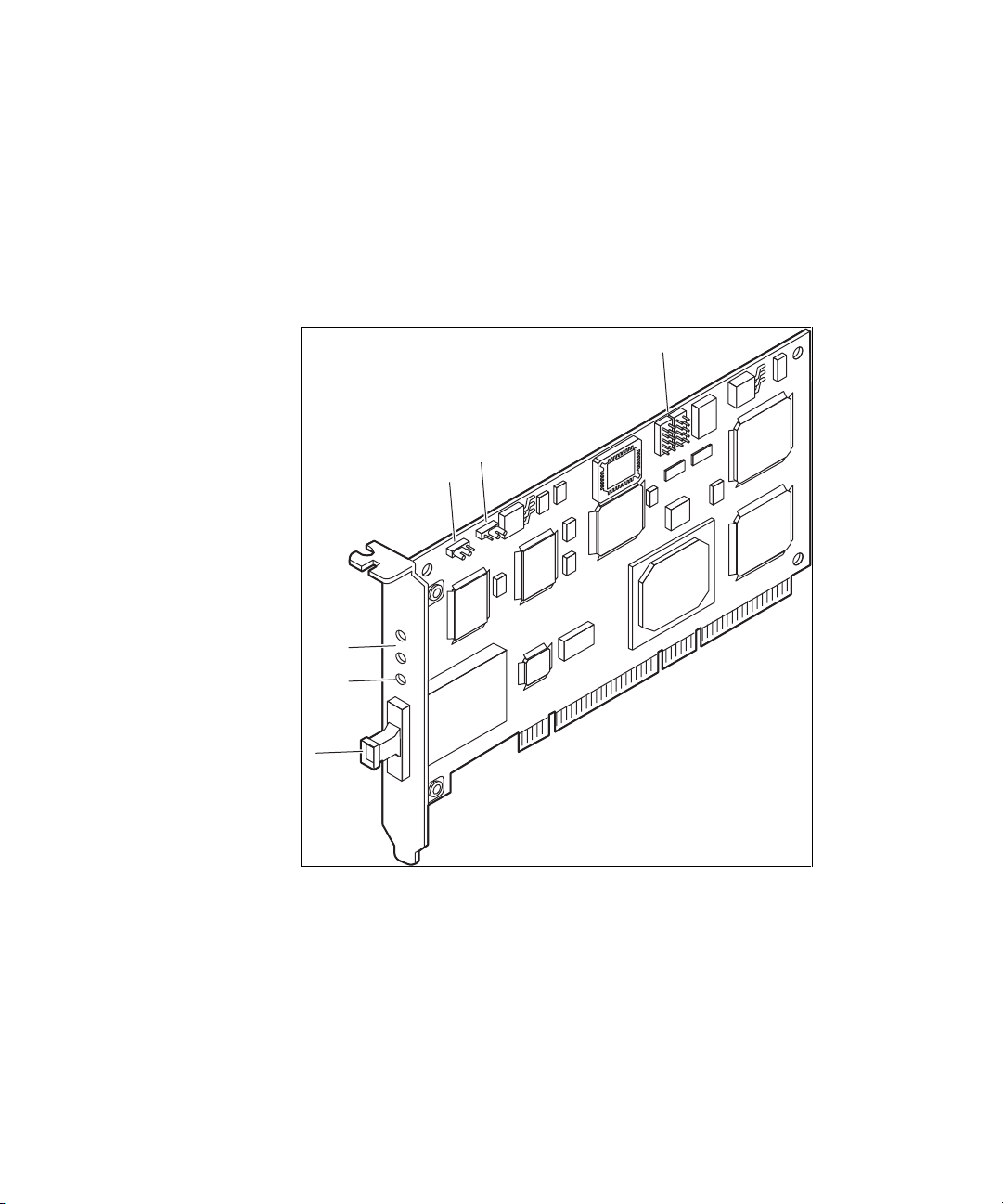
Product Description
The HBA has the following characteristics:
■ Single-slot PCI bus expansion board that interfaces a PCI bus to a fibre
channel device (see Figure 1-1 and Table 1-1).
■ Embedded optical short-wave laser, single-mode fibre channel interface.
■ Supports 32-bit and 64-bit PCI transfers as a bus master during Direct
Memory Access (DMA) transfers and 16-bit transfers as a slave during
Processor Input/Output (PIO) operations.
Page 12
1-2 Compaq StorageWorks 64-Bit PCI-To-Fibre Channel Host Bus Adapter User Guide
Designed using a single custom Application Specific Integrated Circuit
■
(ASIC). The custom ASIC implements a very high performance, multiclass, multi-protocol fibre channel host adapter with a 64-bit PCI bus
connection in a single chip.
■ Supports a full-duplex fibre channel connection at full-link bandwidth
providing a total throughput of greater than 2 Gbits/sec.
■ Controlled by a 233 MHz, 32-bit Intel StrongARM RISC processor.
6
5
4
3
2
1
Figure 1-1. 64-Bit PCI-to-fibre channel host bus adapter
Page 13

Table 1-1
64-Bit PCI-to-Fibre Channel Host Bus Adapter
Figure Legend Description
Introduction 1-3
1
2
3
4
5
6
Jumper Settings
Two jumper blocks (JX1 and JX2) are used to control the HBA’s Device ID.
The default device ID setting for the HBA is F800. The jumper settings
defined in table 1-2 must be maintained for proper HBA operation.
Jumper Pins Description Device ID Comments
JX1 1-2 JX2 disabled F800 Default
Fibre channel connector
LED Indicates the Embedded Optical Receive port is
receiving light.
POST LEDs indicators
Note: see Tables 2-1 and 4-1 for detailed descriptions
Jx1 jumper (see Table 1-2)
Jx2 jumper (see Table 1-2)
Not used
Table 1-2
HBA Jumper Settings
JX2 2-3 F800 Default
Page 14

1-4 Compaq StorageWorks 64-Bit PCI-To-Fibre Channel Host Bus Adapter User Guide
Performance Specifications
The HBA is a high-performance I/O solution for applications such as
client/server configurations, database I/O environments, multimedia
applications, and imaging technologies. Each of these requires high-level
throughput with low-latency characteristics.
The HBA is both ANSI Fibre Channel and PCI Local Bus Compliant and
supports:
■ Full PCI bus speed data transfers of 133 MBytes/sec
■ Point-to-point arbitrated-loop, and switch fabric FC connections
■ Storage protocol
■ Fibre channel class 1, 2, 3
■ Direct interface to fibre optical cables through an embedded SC type
short-wave multi-mode connection
Collectively, these characteristics create a high-performance fibre channel
HBA.
Standards
The HBA conforms to the following standards:
■ ANSI Fibre Channel FC-PH, Revision 4.3
■ ANSI Fibre Channel FC-AL, Revision 4.5
■ PCI Local Bus, Revision 2.0/2.1
■ Fibre Channel Class 1, 2, 3
Page 15

Agency Approvals
The HBA has the following agency approvals:
■ UL Recognized to UL1950
■ CUR Recognized to CSA22.2, No. 950
■ TUV Certified to EN60950
■ FCC Rules, Part 15, Class B
■ DOC Rules, Class B
■ EMC Directive 89/336EEC (CE Mark)
q
EN55022, CISPR22/93, Class B
q
EN50082-1
Introduction 1-5
Page 16

Page 17

Installation Overview
This chapter provides step-by-step instructions for installing the 64-Bit PCI-toFibre Channel Host Bus Adapter (HBA) including:
■ Verification of hardware, software, and document requirements
■ Recording reference numbers
■ Installing the HBA and connecting media
Chapter 2
Installation
This chapter also provides information on installation guidelines and
supported configurations for the operating systems.
IMPORTANT: The HBA contains static-sensitive components. Comply with Electrostatic
Discharge (ESD) procedures.
Hardware Requirements
The system hardware requirements for installing the HBA include:
■ One open 32- or 64-bit PCI bus slot with a 5.0 VDC signaling interface
■ Maximum PCI bus clock rate of 33 MHz
Page 18

2-2 Compaq StorageWorks 64-Bit PCI-To-Fibre Channel Host Bus Adapter User Guide
Software and Documentation Requirements
The following documentation and software kit is supplied with the HBA.
■ User Guide:Part Number 173941-001 (AA-RKPDA-TE)
■ Release Notes: Part Number 173940-001 (AA-RKPEA-TE)
■ Software Replication License: Part Number AV-R9RUA-TE
■ Diskette 1: This diskette contains the following files for Windows NT
4.0 systems.
q
Firmware Download Utility
q
Firmware
q
Readme Files: README FIRST, FIRMWARE README,
DOWNLOAD README, RELEASE NOTES, and USER GUIDE
■ Diskette 2: This diskette contains the following files for Windows NT
4.0 systems.
q
Driver
q
OEMSETUP.INF
q
TXTSETUP.OEM
q
LPSCSI
q
LPUTILNT.EXE
q
Readme Files: README FIRST and LPUTILNT README
■ Diskette 3: This diskette contains the following files for Alpha platforms
running Tru64Unix or OpenVMS operating systems.
q
Firmware Download Utility
q
Firmware
q
Readme Files: README FIRST, FIRMWARE README,
DOWNLOAD README, RELEASE NOTES, and USER GUIDE
Page 19

Recording Reference Numbers
Each HBA ships with a unique address identifier that is stored in flash
memory. Fibre channel industry standards issue two unique identifiers:
WorldWide Port Name (WWPN) and Node Name (NN), each of which is
derived from the HBA’s IEEE address. Combined, the WWPN and NN create
the WorldWide Name (WWN) which is an 8-byte field that uniquely identifies
an HBA on a FC circuit.
Recording the Address and Serial Number
The WWN address and serial number are clearly marked on the HBA. Record
the addresses on the lines below for future reference.
IEEE address: __________________________________________________
Serial number: __________________________________________________
Installing the HBA into a Computer
Following is the procedure for installing the HBA into a computer.
Installation 2-3
WARNING: Be sure to observe the ESD precautions for this procedure.
1. Make sure the computer is powered down and the AC power cord is
disconnected.
2. Remove the screws on the computer cover, and then remove the cover.
3. Remove the blank panel from an empty 32- or 64-bit PCI bus slot.
4. Insert the HBA into the empty PCI bus slot; press firmly until it is
seated securely.
5. Secure the HBA mounting bracket to the computer panel with the panel
screws.
6. Replace the computer cover and secure it using the previously removed
screws.
Page 20

2-4 Compaq StorageWorks 64-Bit PCI-To-Fibre Channel Host Bus Adapter User Guide
Verifying the Installation
To verify the HBA is properly installed and is operating:
1. Connect the computer AC power cord and then turn the computer on.
2. At power up, observe the POST LED indicators on the HBA. The
position of the Post LED indicators is defined in Figure 1-1 and Table 11 of this manual. The green LED indicates power functions and the
yellow LED signifies port activity. The Yellow LED blinks at all times
during normal operation. Table 2-1 lists normal LED indications.
Table 2-1
POST LED Indicators
Green LED Yellow LED State
Off Flashing (irregular) POST processing in progress
On Slow blink (1 Hz) Normal (inactive)
On Flashing (irregular) Normal (active)
On Fast blink (4 Hz) Normal (busy)
Slow blink Off Normal (link down or not yet started)
Configuration Guidelines for Operating Systems
■ Windows NT: The accompanying software for loading the Windows
NT driver also contains the default registry parameter settings that are
loaded as part of the driver installation. The default topology setting is
for FCAL, Topology = 0. Consult the following sources for any
restriction and for information on supported configurations specific to
your operating system and topology.
q
Release Notes
q
ACS Platform Kit for your storage subsystem
q
Compaq Computer Corporation Website
http://www.compaq.com/products/storageworks/adapters.html
Drill down through Services and Support to Adapter Support.
Page 21

Tru64Unix and Open VMS: Refer to your Operating System
■
Installation manual and consult the following sources for any restriction
and for information on supported configurations specific to your
operating system and topology:
q
Release Notes
q
ACS Platform Kit for your storage subsystem
q
Compaq Computer Corporation Website
http://www.compaq.com/products/storageworks/adapters.html
Drill down through Services and Support to Adapter Support.
Installation 2-5
Page 22

Page 23

Introduction
This chapter contains step-by-step instructions for installing the Windows NT
SCSI Miniport driver. This chapter also contains information on the
Tru64Unix and OpenVMS drivers.
System managers must be familiar with the operating system under which the
PCI-to-Fibre Channel Host Bus Adapter (HBA) is to operate. System
managers must also have access to standard system documentation.
Chapter 3
Device Driver Installation
NOTE: This chapter describes the steps for installing the Windows NT device driver and
for accessing fibre channel storage devices. For other configuration changes, see
Chapter 6, “Windows NT Registry Information.”
Windows NT 4.0 System Requirements
Ensure that your system meets these minimum requirements:
■ Installed HBA
■ Windows NT SCSI device driver and registry parameter file from
Diskette 2 of the software kit provided with the HBA
■ Windows NT 4.0 Server with Service Pack 4 or greater
Page 24

3-2 Compaq StorageWorks 64-Bit PCI-To-Fibre Channel Host Bus Adapter User Guide
Installing the Windows NT SCSI Device Driver
This section contains the steps for installing the Windows NT SCSI device
driver on a Windows NT server.
The software kit that is included with the HBA contains the latest version of he
HBA’s files at the time of shipment. Software files are updated periodically
and can be obtained from the Compaq website:
http://www.compaq.com/products/storageworks/adapters.html
Drill down through Services and Support to Adapter Support.
IMPORTANT: The ideal device driver installation includes the possession of a valid
operating system backup.
Following are the steps for installing the Windows NT SCSI device driver and
registry parameters for the first time.
From the Windows NT desktop:
1. Click on Start, select Settings, and then Control Panel.
2. Double click on the SCSI Adapters icon.
3. Select the Drivers tab
4. Click Add.
5. Click Have Disk.
6. Type in the path to the Windows NT SCSI device driver and then click
OK.
7. Select the fibre channel SCSI driver and then click OK.
8. Click Install and continue to install the driver.
9. Reboot the computer to restart Windows NT.
Page 25

Verifying the Device Driver Installation
Verify the driver installation from the Windows NT desktop:
1. Click Start, select Settings, and then Control Panel.
2. Double click the SCSI Adapters icon.
3. Select the Drivers tab.
Verify that the Emulex SCSI mini-port driver is present and started.
4. Select the Default tab.
Verify that the HBA is present.
5. Click the + symbol to expand the adapter list.
Verify that the connected storage device is listed.
Removing the Device Driver
To remove the device driver from the Windows NT desktop:
1. Click Start, select Settings, and then Control Panel.
Device Driver Installation 3-3
2. Double click the SCSI Adapters icon.
3. Select the Drivers tab.
4. Click Remove.
5. Select Yes to confirm.
6. Click OK.
7. Reboot the computer to restart Windows NT.
Page 26

3-4 Compaq StorageWorks 64-Bit PCI-To-Fibre Channel Host Bus Adapter User Guide
Tru64Unix Driver and Console Software
The HBA driver is built into the Tru64Unix operating systems and supported
by Console software. For the supported versions of Tru64Unix operating
systems and Console software, consult the HBA Release Notes included in this
documentation package. Release notes are updated periodically and can be
obtained from the Compaq website:
http://www.compaq.com/products/storageworks/adapters.html
Drill down through Services and Support to Adapter Support.
See the documentation specific to your platform for detailed information on
installing the appropriate operating system and Console software.
-SHOW ADAPTER / -SET ADAPTER Commands
V5.6 SRM console and higher revisions have the capability of setting an HBA
to run in arbitrated loop mode or in fabric (switch) mode. If an HBA in loop
mode is connected to a switch, the results are unpredictable. The same is true
for an HBA in fabric mode that is connected to a loop. By default, the console
assumes a fabric topology. The SET ADAPTER command stores the selected
topology into the NVRAM storage on the HBA. If the HBA is moved from
one AlphaServer to another, this setting stays with the HBA. The V5.6 or
greater supports the FCAL (loop) topology. A setting of loop is a valid setting
in V5.6, however, that setting prompts the console driver not to run.
Refer to the WWIDGR manual at the following location for detailed
information on the – SHOW ADAPTER and – SET ADAPTER commands:
http://ftp.digital.com/pub/DEC/Alpha/firmware/v5.6/doc/wwidmgr.pdf
NOTE: In order for the – SHOW ADAPTER and – SET ADAPTER commands to be accepted
by the system, the console must first be set to diagnostic mode (set mode diag).
Page 27

Device Driver Installation 3-5
-SHOW ADAPTER Command
The HBA configuration can be displayed with the command (see Figures 3-1
and 3-2):
WWIDMGR-SHOW ADAPTER
P00>>>wwidmgr-show adapter
Item adapter WWN Cur. Topo Next Topo
kgpsaa0.0.0.4.6 – Nvram read failed
[0] kgpsaa0.0.0.4.6 1000-0000-c921-0c22 fabric unavail
kgpsab0.0.0.8.6 – Nvram read failed
[1] kgpsab0.0.0.8.6 1000-0000-c921-027a loop unavail
[9999] All of the above.
Figure 3-1. – SHOW ADAPTER with an unformatted NVRAM
In Figure 3-1, note the warning message “ Nvram Read Failed.” This indicates
that the NVRAM on the HBA has not been initialized and formatted. This is
expected and can be corrected by issuing a – SET ADAPTER command as
described in the next section.
LP00>>>wwidmgr-show adapter
Item adapter WWN Cur. Topo Next Topo
[0] kgpsaa0.0.0.4.6 1000-0000-c921-05ab fabric fabric
[1] kgpsab0.0.0.8.6 1000-0000-c921-0ce0 fabric fabric
[9999] All of the above.
Figure 3-2. – SHOW ADAPTER display
Figure 3-2 shows a display from WWIDMGR-SHOW ADAPTER where there
are two HBAs in the system. See the following for a detailed look at a line
item:
[0] kgpsaa0.0.0.4.6 1000-0000-c921-05ab fabric fabric
■ [0] − Item Number. The bracketed value is used as a parameter to the
–item qualifier in the WWIDMGR-SET ADAPTER command. You can
select which HBA to configure by its item number. An item number of
9999 selects all HBAs.
■ Kgpsaa0.0.0.4.6 − Adapter Mnemonic. Error messages and displays use
this identifier.
■ 1000-0000-c920-05ab − WWN of the HBA. This value is used to
identify the HBA to other nodes on the fibre channel link.
Page 28

3-6 Compaq StorageWorks 64-Bit PCI-To-Fibre Channel Host Bus Adapter User Guide
Fabric − Current Topology. This value is either fabric or loop. It
■
indicates the mode in which the HBA is operating currently, during this
WWIDMGR session. The current mode in which the HBA is running is
not altered during a WWIDMGR session.
■ Fabric − Next Topology. This value can be fabric, loop, or unavail. It
indicates the topology setting that is in the HBA’s NVRAM. An unavail
setting indicates the NVRAM is not formatted, a condition corrected by
a – SET ADAPTER command. A setting of fabric or loop indicates how
the HBA is configured the next time the system is initialized.
■ – SET ADAPTER – A WWIDMGR-SET ADAPTER command is used
to format the HBA NVRAM and to configure an HBA to run on a loop
or a fabric. The command format is:
wwidmgr-set adapter -item<itemno> -topo<fabricIloop>
where itemno is the bracketed value from the – SHOW ADAPTER
command. In Figure 3-3, you can change all HBA’s from fabric to loop
by specifying an itemno value of 9999. The init is shown at the end to
emphasize that the setting in the running HBA is not changed until the
next initialization.
LP00>>>wwidmgr-show ada
Item adapter WWN Cur. Topo Next Topo
[0] kgpsaa0.0.0.8.1 1000-0000-c920-05ab fabric fabric
[1] kgpsab0.0.0.10.1 1000-0000-c921-0ce0 fabric fabric
[9999] All of the above
LP00>>>wwidmgr-set adapter – item 9999 – topo loop
LP00>>>wwidmgr-show ada
Item adapter WWN Cur. Topo Next Topo
[0] kgpsaa0.0.0.8.1 1000-0000-c920-05ab fabric loop
[1] kgpsab0.0.0.10.1 1000-0000-c921-0ce0 fabric loop
[9999] All of the above.
LP00>>>init
Figure 3-3. – SET ADAPTER example
Page 29

OpenVMS Driver and Console Software
The HBA driver is built into the OpenVMS operating system, TIMA Kit, and
supported by Console software. For the supported versions of OpenVMS
operating systems, TIMA Kit and Console software, see the HBA Release
Notes included in this documentation package. Release notes are updated
periodically and can be obtained from the Compaq website:
http://www.compaq.com/products/storageworks/adapters.html
Drill down through Services and Support to Adapter Support.
See the documentation specific to your platform for detailed information on
installing the appropriate operating system and Console software.
Device Driver Installation 3-7
Page 30

Page 31

Introduction
The Power-On Self Test (POST), valid for Windows NT, Tru64Unix, and
OpenVMS operating systems and the Windows NT System Event Logger
(Viewer) are troubleshooting utilities for the 64-Bit PCI-To-Fibre Channel
Host Bus Adapter (HBA). This chapter explains the use of these utilities in
the event of an HBA problem.
POST Conditions and Results
Chapter 4
Troubleshooting
Table 4-1 lists the HBA LED states with descriptions of each. . The position
of the Post LED indicators is defined in Figure 1-1 and Table 1-1 of this
manual.
If the LEDs indicate a failure during POST:
1. Make sure that the HBA is seated firmly in the PCI slot.
2. Verify that the fibre cable connection to the HBA is secure.
Page 32

4-2 Compaq StorageWorks 64-Bit PCI-To-Fibre Channel Host Bus Adapter User Guide
Table 4-1
HBA POST LED States
Green LED Yellow LED Description
Off Off Wake-up failure (inoperable HBA)
Off On POST failure (inoperable HBA)
Off Slow blink (1 Hz) Wake-up failure
Off Fast blink (4 Hz) Failure in POST
Off Flashing (irregular) POST processing in progress
On Off Failure while functioning
On On Failure while functioning
On Slow blink (1 Hz) Normal (inactive)
On Flashing (irregular) Normal (active)
On Fast blink (4 Hz) Normal (busy)
Slow blink Off Normal (link down or not yet started)
Slow blink Slow blink (1 Hz) Off-line for download
Slow blink Fast blink (4 Hz) Restricted off-line mode (waiting for restart)
The Windows NT Event Viewer
The Windows NT SCSI driver verifies the condition of the HBA POST. If
there is a failure or a suspected failure, an error log entry is issued to the
Windows NT System Event Logger (Viewer).
Following is the procedure for viewing the Windows NT error log.
From the Main menu:
1. Double click or select the Administrative Tools program group.
2. Double click or select the Event Viewer. The display shows a list of
discrete events specifying the source name LP8NDS35 (NT SCSI
driver).
3. Double click any event with the source name LP8NDS35.
Page 33

4. Change the data view from Bytes (default) to Words.
5. Examine the entry at offset 0x10: if the low byte = En, match the low
byte with the error found in Table 4-2, Windows NT SCSI Port Error
Log. Tables 4-3 and 4-4 list CmdStat values and Parameter error
values.
Windows NT Miniport Event Log Codes
The Windows NT Miniport driver can log events/errors in the Windows NT
event log. Serious errors will always be logged. Informational events will
only be logged if the registry parameter LogError=1 is used.
All Miniport logged events are issued with an Event ID of 11 (INTERNAL
ADAPTER ERROR) but do not necessarily indicate an HBA error occurred.
Byte offset 0x10 of the event is the driver event code. Byte offsets 0x11 to
0x13 contain event specific information.
Table 4-2
Windows NT SCSI Port Error Log
Troubles hooting 4-3
0x10
Offset
0xD0 SNS_REQ (XMIT_SEQ failed) 0x11 = cmdstat, 12 = parm err
0xD1 SNS_RSP (RCV_SEQ failed) 0x11 = cmdstat, 12 = parm err
0xD3 RCV_ELS_REQ failed 0x11 = cmdstat, 12 = parm err
0xD4 XMT_ELS_REQ failed 0x11 = cmdstat, 12 = parm err
0xD5 Too many targets found (160+) 0x11 to 13 = D_DID that didn’t fit
0xD6 SNS request time-out 0x11 to 13 no additional information
0xD7 Mailbox interrupt time-out 0x11 = mailbox word 0
0xD8 TPRLO requested when busy 0x11 = local req. state, 12 =
0xD9 Link down time-out occurred 0x11 = local req. state, 12 =
Explanation 0x11 to 0x13 Further Information
discstate, 13 = mailbox word 0
discstate, 13 = mailbox word 0
continued
Page 34

4-4 Compaq StorageWorks 64-Bit PCI-To-Fibre Channel Host Bus Adapter User Guide
Table 4-2
Windows NT SCSI Port Error Log
0x10
Offset
Explanation 0x11to 0x13 Further Information
continued
0xDA Hard link down time-out
occurred
0xE0 Node purged from configuration 0x11 to 0x13 = D_ID of node purged
0xE1 Error interrupt occurred
0xE2 Mailbox cmd time-out 0x11 = command
0xE3 Mailbox rsp err 0x11 = command, 12-13 = mbxstatus
0xE4 HBA not ready after init Status register bytes 1-3 in event 11-
0xE5 Requested loop but link = PT-
PT
0xE6 Mailbox int. but cmd not
complete
0xE7 SRB already queued to ring
0xE8 RESTART failed
0xE9 PORT BYPASS (LPB) received
0xEB Unknown IOCB cmd rsp 0x11 = 15:8 = cmd field
0xEC Uncached extension alloc. Error
0xED Link down @ boot time (30 sec)
0x11 = local req. state, 12 =
discstate, 13 = mailbox word 0
Status register bytes 1-3 in event 11-
13. E1 error indicates an HBA
hardware failure, return HBA for repair.
13
0x11 = MB cmd, 12-13 = mbxstatus
0xEF Too many interrupts at initial
boot
0xF0 Rcv ELS request (possible
logout)
0xF1 LinkUp error; LP8 down, driverup0x11 = parameter field, 12 = IOCB
0xF2 LinkUp w/ illegal or corrupt RPI 0x11 = parameter field, 12 = IOCB
0x11 = ELS type, 12-13 = X_ID
cmd
cmd
continued
Page 35

Troubles hooting 4-5
Table 4-2
Windows NT SCSI Port Error Log
0x10
Offset
0xF3 DeQueue ring->iotcmd.head 0x11 = caller ID
0xF4 HBA reset 0x11 = coded reason for reset:
0xF5 PCP_IXXX_CR IOCB rsp err 0x11 = cmdstat, 12 = parm err, 13 =
0xF6 PCP_IXXX_CR IOCB rsp err 0x11 = cmdstat, 12 = parm err, 13 =
0xF7 Ring hd !=0 &&
0xF8 Invalid FCP_RSP 0x11 = pcpcntrl, 12 = scsisat, 13 =
Explanation 0x11 to 0x13 Further Information
pendingsrb!=NULL
continued
Bit 0 = IOCB requeue; bit 1 = readla
retry
Bit 2 = initlink retry; bit 3 = rstbus
retry
Bit 4 = mailbox time-out
ALPA
ALPA
len
0xF9 Two consec. time-outs, issue
LIP
0xFA START_IO error 0x11 = errtype, 12 = srbstat, 13 =
linkup
0xFB ELS_REQ_CR IOCB rsp err 0x11 = cmdstat, 12 = parm err, 13 =
ALPA
0xFC ELS_REQ_CR IOCB rsp err
0xFE FLOGI failed 0x11 = cmdstat, 12 = parm err
0xFF SNS_PLOGI failed 0x11 = cmdstat, 12 = parm err
0x11 = cmdstat, 12 = parm err, 13 =
ALPA
Page 36

4-6 Compaq StorageWorks 64-Bit PCI-To-Fibre Channel Host Bus Adapter User Guide
Table 4-3
CmdStat Values
0x11
Offset
0x1 IOSTAT_FCP_RSP_ERR
0x2 IOSTAT_REMOTE_STOP Remote sent an ABTS
0x3 IOSTAT_LOCAL_REJECT Parameter field contains additional
0x4 IOSTAT_NPORT_RJT
0x5 IOSTAT_FABRIC_RJT
0x6 IOSTAT_NPORT_BSY
0x7 IOSTAT_FBRIC_BSY
0x8 IOSTAT_INTERMED_RSP
0x9 IOSTAT_LS_RJT
0xA IOSTAT_BA_RJT
Explanation Further Information
info
Table 4-4
Parameter Error Values (valid only when CmdStat=0x3)
0x12 Offset Explanation
0x00 IOERR_SUCCESS
0x01 IOERR_MISSING_CONTINUE
0x02 IOERR_SEQUENCE_TIMEOUT
0x03 IOERR_INTERNAL_ERROR
0x04 IOERR_INVALID_RPI
0x05 IOERR_NO_XRI
0x06 IOERR_ILLEGAL_COMMAND
0x07 IOERR_XCHG_DROPPED
0x08 IOERR_ILLEGAL_FIELD
continued
Page 37

Table 4-4
Parameter Error Values (valid only when CmdStat=0x3)
0x12 Offset Explanation
0x09 IOERR_BAC_CONTINUE
0x0A IOERR_TOO_MANY_BUFFERS
0x0B IOERR_RCV_BUFFER_WAITING
0x0C IOERR_NO_CONNECTION
0x0D IOERR_TX_DMA_FAILED
0x0E IOERR_RX_DMA_FAILED
0x0F IOERR_ILLEGAL_FRAME
0x10 IOERR_EXTRA_DATA
0x11 IOERR_NO_RESOURCES
0x12 IOERR_RESERVED
0x13 IOERR_ILLEGAL_LENGTH
0x14 IOERR_UNSUPPORTED_FEATURE
0x15 IOERR_ABORT_IN_PROGRESS
Troubles hooting 4-7
continued
0x16 IOERR_ABORT_REQUESTED
0x17 IOERR_RECEIVE_BUFFER_TIMEOUT
0x18 IOERR_LOOP_OPEN_FAILURE
0x19 IOERR_RING_RESET
0x1A IOERR_LINK_DOWN
0x1B IOERR_CORRUPTED_DATA
0x1C IOERR_CORRUPTED_RPI
0x1D IOERR_OUT_OF_ORDER
0x1E IOERR_OUT_OF_ORDER_ACK
0x1F IOERR_DUPLICATE_FRAME
0x20 IOERR_INVALID_ACK
0x21 IOERR_BAD_40BIT_ADDRESS
continued
Page 38

4-8 Compaq StorageWorks 64-Bit PCI-To-Fibre Channel Host Bus Adapter User Guide
Table 4-4
Parameter Error Values (valid only when CmdStat=0x3)
0x12 Offset Explanation
0x22 IOERR_RESERVED
0x23 IOERR_RESERVED
0x24 IOERR_RESERVED
0x25 IOERR_ABORT_MULTI_REQUESTED
0x26 IOERR_RESERVED
0x27 IOERR_RESERVED
0x28 IOERR_LINK_BUFFER_SHORTAGE
0x29 IOERR_RCV_XRIBUF_WAITING
Windows NT SCSI Address Mapping
The driver emulates six SCSI buses per HBA to map all 126 possible AL_PA
to Target IDs.
continued
The first bus is a dummy bus used to delay the Windows NT initial inquiry
scan until after discovery completes. The 31 target IDs per bus (Windows NT
requires the initiator to consume one of the IDs, we use #31) are then mapped
to either ascending or descending SEL_IDs (based on the ScanDown registry
parameter).
NOTE: The first bus will be utilized if the parameter MapBus0=1 is used.
Fabric Device Mapping
In a fabric (switched) environment, devices are initially created based on the
order that they are returned from the Simple Name Server (SNS). Once
created (at boot), the devices continue to be tracked based on:
– WWPN: HardAddress=0;MapNodeName=0
– NodeName: HardAddress=0;MapNodeName=1
– D_ID: HardAddress=1; (MapNodeName=don’t care)
Page 39

Private Loop Device Mapping
In a private loop environment (FCAL, no switch), devices are initially created
based on a fixed address ordering. Once created (at boot), the devices
continue to be tracked based on:
– WWPN: HardAddress=0;MapNodeName=0
– NodeName: HardAddress=0;MapNodeName=1
– D_ID: HardAddress=1; (MapNodeName=don’t care)
This section identifies the initial fixed mapping between the Windows NT
bus/target/lun and a fibre channel native address (AL_PA/SEL_ID). There are
two potential mappings based on a registry parameter [ScanDown=0 (driver
default); use *, ScanDown=1;].
The index into Table 4-5 can be derived by:
#define TARGETS_PER_BUS 32
i = (Srb->PathId > 0) ? Srb->PathId-1 : 0; //Bus 0 = dummy bus nodeInx = ((I *
(TARGETS_PER_BUS-1)) + Srb->TargetId;
Current Private Loop Device Mapping
Troubles hooting 4-9
Table 4-5
Bus #
0
1*** 0 0-7 0x01 0x7D 0xEF 0x00
Target#
0-31
1 0-7 0x02 0x7C 0xE8 0x01
2 0-7 0x04 0x7B 0xE4 0x02
3 0-7 0x08 0x7A 0xE2 0x03
4 0-7 0x0F 0x79 0xE1 0x04
5 0-7 0x10 0x78 0xE0 0x05
6 0-7 0x17 0x77 0xDC 0x06
Lun#
0-7
*AL_PA
None
*SEL_ID
None
**AL_PA
None
* Use this translation if registry ScanDown = 0 (default)
** Use this translation if registry ScanDown = 1
*** If MapBus0=1;, then device addressing starts with Bus #0, not #1
**SEL_ID
None
continued
Page 40

4-10 Compaq StorageWorks 64-Bit PCI-To-Fibre Channel Host Bus Adapter User Guide
Table 4-5
Current Private Loop Device Mapping
Bus #
0
Target#
0-31
7 0-7 0x18 0x76 0xDA 0x07
8 0-7 0x1B 0x75 0xD9 0x08
9 0-7 0x1D 0x74 0xD6 0x09
10 0-7 0x1E 0x73 0xD5 0x0A
11 0-7 0x1F 0x72 0xD4 0x0B
12 0-7 0x23 0x71 0xD3 0x0C
13 0-7 0x25 0x70 0xD2 0x0D
14 0-7 0x26 0x6F 0xD1 0x0E
15 0-7 0x27 0x6E 0xCE 0x0F
16 0-7 0x29 0x6D 0xCD 0x10
17 0-7 0x2A 0x6C 0xCC 0x11
18 0-7 0x2B 0x6B 0xCB 0x12
Lun#
0-7
continued
*AL_PA
None
*SEL_ID
None
**AL_PA
None
**SEL_ID
None
19 0-7 0x2C 0x6A 0xCA 0x13
20 0-7 0x2D 0x69 0xC9 0x14
21 0-7 0x2E 0x68 0xC7 0x15
22 0-7 0x31 0x67 0xC6 0x16
23 0-7 0x32 0x66 0xC5 0x17
24 0-7 0x33 0x65 0xC3 0x18
25 0-7 0x34 0x64 0xBC 0x19
26 0-7 0x35 0x63 0xBA 0x1A
* Use this translation if registry ScanDown = 0 (default)
** Use this translation if registry ScanDown = 1
*** If MapBus0=1;, then device addressing starts with Bus #0, not #1
continued
Page 41

Table 4-5
Current Private Loop Device Mapping
Bus #
0
2***
Target#
0-31
27 0-7 0x36 0x62 0xB9 0x1B
28 0-7 0x37 0x61 0xB6 0x1C
29 0-7 0x3A 0x60 0xB5 0x1D
30 0-7 0x3C 0x5F 0xB4 0x1E
31 0-7 None None None None
0 0-7 0x43 0x5E 0xB3 0x1F
1 0-7 0x45 0x5D 0xB2 0x20
2 0-7 0x46 0x5C 0xB1 0x21
3 0-7 0x47 0x5B 0xAE 0x22
4 0-7 0x49 0x5A 0xAD 0x23
5 0-7 0x4A 0x59 0xAC 0x24
6 0-7 0x4B 0x58 0xAB 0x25
Lun#
0-7
continued
*AL_PA
None
*SEL_ID
None
**AL_PA
None
Troubles hooting 4-11
**SEL_ID
None
7 0-7 0x4C 0x57 0xAA 0x26
8 0-7 0x4D 0x56 0xA9 0x27
9 0-7 0x4E 0x55 0xA7 0x28
10 0-7 0x51 0x54 0xA6 0x29
11 0-7 0x52 0x53 0xA5 0x2A
12 0-7 0x53 0x52 0xA3 0x2B
13 0-7 0x54 0x51 0x9F 0x2C
14 0-7 0x55 0x50 0x9E 0x2D
* Use this translation if registry ScanDown = 0 (default)
** Use this translation if registry ScanDown = 1
*** If MapBus0=1;, then device addressing starts with Bus #0, not #1
continued
Page 42

4-12 Compaq StorageWorks 64-Bit PCI-To-Fibre Channel Host Bus Adapter User Guide
Table 4-5
Current Private Loop Device Mapping
Bus #
0
Target#
0-31
15 0-7 0x56 0x4F 0x9D 0x2E
16 0-7 0x59 0x4E 0x9B 0x2F
17 0-7 0x5A 0x4D 0x98 0x30
18 0-7 0x5C 0x4C 0x97 0x31
19 0-7 0x63 0x4B 0x90 0x32
20 0-7 0x65 0x4A 0x8F 0x33
21 0-7 0x66 0x49 0x88 0x34
22 0-7 0x67 0x48 0x84 0x35
23 0-7 0x69 0x47 0x82 0x36
24 0-7 0x6A 0x46 0x81 0x37
25 0-7 0x6B 0x45 0x80 0x38
26 0-7 0x6C 0x44 0x7C 0x39
Lun#
0-7
continued
*AL_PA
None
*SEL_ID
None
**AL_PA
None
**SEL_ID
None
27 0-7 0x6D 0x43 0x7A 0x3A
28 0-7 0x6E 0x42 0x79 0x3B
29 0-7 0x71 0x41 0x76 0x3C
30 0-7 0x72 0x40 0x75 0x3D
31 0-7 None None None None
* Use this translation if registry ScanDown = 0 (default)
** Use this translation if registry ScanDown = 1
*** If MapBus0=1;, then device addressing starts with Bus #0, not #1
continued
Page 43

Table 4-5
Current Private Loop Device Mapping
Bus #
0
3***
Target#
0-31
0 0-7 0x73 0x3F 0x74 0x3E
1 0-7 0x74 0x3E 0x73 0x3F
2 0-7 0x75 0x3D 0x72 0x40
3 0-7 0x76 0x3C 0x71 0x41
4 0-7 0x79 0x3B 0x6E 0x42
5 0-7 0x7A 0x3A 0x6D 0x43
6 0-7 0x7C 0x39 0x6C 0x44
7 0-7 0x80 0x38 0x6B 0x45
8 0-7 0x81 0x37 0x6A 0x46
9 0-7 0x82 0x36 0x69 0x47
10 0-7 0x84 0x35 0x67 0x48
11 0-7 0x88 0x34 0x66 0x49
Lun#
0-7
continued
*AL_PA
None
*SEL_ID
None
**AL_PA
None
Troubles hooting 4-13
**SEL_ID
None
12 0-7 0x8F 0x33 0x65 0x4A
13 0-7 0x90 0x32 0x63 0x4B
14 0-7 0x97 0x31 0x5C 0x4C
15 0-7 0x98 0x30 0x5A 0x4D
16 0-7 0x9B 0x2F 0x59 0x4E
17 0-7 0x9D 0x2E 0x56 0x4F
18 0-7 0x9E 0x2D 0x55 0x50
19 0-7 0x9F 0x2C 0x54 0x51
* Use this translation if registry ScanDown = 0 (default)
** Use this translation if registry ScanDown = 1
*** If MapBus0=1;, then device addressing starts with Bus #0, not #1
continued
Page 44

4-14 Compaq StorageWorks 64-Bit PCI-To-Fibre Channel Host Bus Adapter User Guide
Table 4-5
Current Private Loop Device Mapping
Bus #
0
4***
Target#
0-31
20 0-7 0xA3 0x2B 0x53 0x52
21 0-7 0xA5 0x2A 0x52 0x53
22 0-7 0xA6 0x29 0x51 0x54
23 0-7 0xA7 0x28 0x4E 0x55
24 0-7 0xA9 0x27 0x4D 0x56
25 0-7 0xAA 0x26 0x4C 0x57
26 0-7 0xAB 0x25 0x4B 0x58
27 0-7 0xAC 0x24 0x4A 0x59
28 0-7 0xAD 0x23 0x49 0x5A
29 0-7 0xAE 0x22 0x47 0x5B
30 0-7 0xB1 0x21 0x46 0x5C
31 0-7 None None None None
0 0-7 0xB2 0x20 0x45 0x5D
Lun#
0-7
continued
*AL_PA
None
*SEL_ID
None
**AL_PA
None
**SEL_ID
None
1 0-7 0xB3 0x1F 0x43 0x5E
2 0-7 0xB4 0x1E 0x3C 0x5F
3 0-7 0xB5 0x1D 0x3A 0x60
4 0-7 0xB6 0x1C 0x39 0x61
5 0-7 0xB9 0x1B 0x36 0x62
* Use this translation if registry ScanDown = 0 (default)
** Use this translation if registry ScanDown = 1
*** If MapBus0=1;, then device addressing starts with Bus #0, not #1
continued
Page 45

Table 4-5
Current Private Loop Device Mapping
Bus #
0
Target#
0-31
6 0-7 0xBA 0x1A 0x35 0x63
7 0-7 0xBC 0x19 0x34 0x64
8 0-7 0xC3 0x18 0x33 0x65
9 0-7 0xC5 0x17 0x32 0x66
10 0-7 0xC6 0x16 0x31 0x67
11 0-7 0xC7 0x15 0x2E 0x68
12 0-7 0xC9 0x14 0x2D 0x69
13 0-7 0xCA 0x13 0x2C 0x6A
14 0-7 0xCB 0x12 0x2B 0x6B
15 0-7 0xCC 0x11 0x2A 0x6C
16 0-7 0xCD 0x10 0x29 0x6D
17 0-7 0xCE 0x0F 0x27 0x6E
Lun#
0-7
continued
*AL_PA
None
*SEL_ID
None
**AL_PA
None
Troubles hooting 4-15
**SEL_ID
None
18 0-7 0xD1 0x0E 0x26 0x6F
19 0-7 0xD2 0x0D 0x25 0x70
20 0-7 0xD3 0x0C 0x23 0x71
21 0-7 0xD4 0x0B 0x1F 0x72
22 0-7 0xD5 0x0A 0x1E 0x73
23 0-7 0xD6 0x09 0x1D 0x74
24 0-7 0xD9 0x08 0x1B 0x75
25 0-7 0xDA 0x07 0x18 0x76
* Use this translation if registry ScanDown = 0 (default)
** Use this translation if registry ScanDown = 1
*** If MapBus0=1;, then device addressing starts with Bus #0, not #1
continued
Page 46

4-16 Compaq StorageWorks 64-Bit PCI-To-Fibre Channel Host Bus Adapter User Guide
Table 4-5
Current Private Loop Device Mapping
Bus #
0
5***
Target#
0-31
26 0-7 0xDC 0x06 0x17 0x77
27 0-7 0xE0 0x05 0x10 0x78
28 0-7 0xE1 0x04 0x0F 0x79
29 0-7 0xE2 0x03 0x08 0x7A
30 0-7 0xE4 0x02 0x04 0x7B
31 0-7 None None None None
0 0-7 0xE8 0x01 0x02 0x7C
1 0-7 0xEF 0x00 0x01 0x7D
2 0-7 None None None None
3 0-7 None None None None
4 0-7 None None None None
5 0-7 None None None None
Lun#
0-7
continued
*AL_PA
None
*SEL_ID
None
**AL_PA
None
**SEL_ID
None
6 0-7 None None None None
7 0-7 None None None None
8 0-7 None None None None
9 0-7 None None None None
10 0-7 None None None None
11 0-7 None None None None
12 0-7 None None None None
* Use this translation if registry ScanDown = 0 (default)
** Use this translation if registry ScanDown = 1
*** If MapBus0=1;, then device addressing starts with Bus #0, not #1
continued
Page 47

Table 4-5
Current Private Loop Device Mapping
Bus #
0
Target#
0-31
13 0-7 None None None None
14 0-7 None None None None
15 0-7 None None None None
16 0-7 None None None None
17 0-7 None None None None
18 0-7 None None None None
19 0-7 None None None None
20 0-7 None None None None
21 0-7 None None None None
22 0-7 None None None None
23 0-7 None None None None
24 0-7 None None None None
Lun#
0-7
continued
*AL_PA
None
*SEL_ID
None
**AL_PA
None
Troubles hooting 4-17
**SEL_ID
None
25 0-7 None None None None
26 0-7 None None None None
27 0-7 None None None None
28 0-7 None None None None
29 0-7 None None None None
30 0-7 None None None None
31 0-7 None None None None
* Use this translation if registry ScanDown = 0 (default)
** Use this translation if registry ScanDown = 1
*** If MapBus0=1;, then device addressing starts with Bus #0, not #1
Page 48

Page 49

Introduction
This chapter contains installation and user instructions for the diagnostic and
firmware download utility. This utility is a DOS-based program used
exclusively in standalone environments.
NOTE: The diagnostic and firmware download utility is used to upgrade firmware on both
versions of the 64-Bit PCI-to-Fibre Channel Host Bus Adapters (HBAs).
Chapter 5
Firmware and Diagnostic Utility
The Diagnostic and Firmware Download Utility
The supplied software kit contains the Alpha and the i386 system diagnostic
and firmware download utility, for their respective hosts. The diagnostic
utility for each host is stored in the host specific directory. For Alpha systems
the utility is ALPHDNLD.EXE and for i386 systems the utility is
I386DNLD.EXE. The common HBA firmware is located in the root directory.
Page 50

5-2 Compaq StorageWorks 64-Bit PCI-To-Fibre Channel Host Bus Adapter User Guide
Functionally, the utility program performs:
■ Discovery and preliminary testing of the HBA in the system.
■ Functional testing and operational checks on the HBA.
■ The use of input and output files to automate the execution of the
diagnostic utility program.
■ Updating HBA firmware.
NOTE: The diagnostic utility does not operate in the DOS shell under Windows.
i386 System Installation
You must load the software and start the diagnostic utility from the DOS
command line. You can execute I386DNLD.EXE directly from the supplied
software kit or you can load onto your hard drive and execute it from there.
To install the I386DNLD.EXE onto the hard drive:
1. Insert the supplied diskette into your system’s diskette drive.
2. Make a directory and copy the files onto your hard drive, as follows:
C:\md dir_name
C:\copy A:\i386\*.*c:\dir_name
C:\cd dir_name
Where:
Dir_name is the directory where the diagnostic software is stored.
Starting I386DNLD.EXE in an i386 System
To start the I386DNLD.EXE program without any options, type:
From the system disk:
C:\I386DNLD.EXE
From the diskette:
A:/i386DNLD.EXE
The options for I386DNLD.EXE are listed in Table 5-1. The syntax for using
options is:
Page 51

Firmware and Diagnostic Utility 5-3
C:\ I386DNLD.EXE { I = infilename} {o = outfilename}
Following is a sample command:
C:\ I386DNLD.EXE o = pciha001
Where pciha001 is the output filename.
Table 5-1
I386DNLD.EXE Command Options
Option Description
Infilename Script input file that is read and executed by the program.
Outfilename
NOTE: All message lines except user input begin with a # symbol to indicate a comment
line. User entered data appears on a line by itself, not preceded by a #.
Creates a file of keystrokes that is stored for later use (for example,
as an input file).
Starting Alpha Systems with Alpha BIOS
Following is the procedure for starting ALPHDNLD.EXE on systems running
Alpha BIOS:
1. If the system default is NT, at startup, press the F2 key for setup. When
the Alpha BIOS screen comes up, go to Step 3.
2. If the system default is SRM, type ARC at the SRM console. When the
Alpha BIOS initialization screen comes up, press the F2 key for setup,
go to Step 3.
3. Select Run Maintenance Program from the Utilities menu. The run
Maintenance Program window comes up.
4. Insert the diskette into your computer’s diskette drive.
5. Type: A:/ ALPHDNLD.EXE and press the Enter key.
Go to the “ Start-up for Alpha/i386 System” section.
Page 52

5-4 Compaq StorageWorks 64-Bit PCI-To-Fibre Channel Host Bus Adapter User Guide
Start-Up for Alpha/i386 Systems
The diagnostic program performs preliminary analysis of the HBA before
displaying its Main menu. If no HBA is found, the program exits. Error
messages are displayed on failure conditions.
During startup, the diagnostic and firmware download utility program:
1. Looks for installed PCI HBAs.
2. Executes preliminary testing on all installed HBAs. Tests include:
a. SLIM memory test.
b. BIU register test.
c. BIU configuration registers test.
3. Reports pass or fail status messages.
4. Resets the HBAs.
5. Checks Power-On Self Test (POST) status of HBAs.
6. Reports revision levels of diagnostic and functional firmware.
7. Displays the resources of each HBA.
The following is a sample output of the diagnostic and firmware download
utility Start-Up Procedure.
WELCOME TO HOST DIAGNOSTIC UTILITY Revision x.x
Host Adapters found in the system: 1
PRELIMINARY TESTING of Host Adapter 1
Host Adapter 1: PASS 0xA: SLIM Memory Tests
WELCOME TO HOST DIAGNOSTIC UTILITY Revision x.x
Host Adapter 1: Pass 0xA: BIU Registers Tests
Host Adapter 1: Pass 0xA: BIU Configuration Registers Tests
Adapter 1 PASSED PRELIMINARY TESTS
Page 53

Firmware and Diagnostic Utility 5-5
WELCOME TO HOST DIAGNOSTIC UTILITY Revision x.x
Resetting Host Adapter: 1
Host Adapter 1: Post Done.
Host Adapter 1 is READY. Functional Firmware Loaded.
Diagnostic Firmware Version x.x
Functional Firmware Version x.x
HIT RETURN or ENTER key to continue
<return>
HOST ADAPTER 1 Resources Info
Pci_bus_num = 0 Pci_dev_num = 0xA0
Slim_base_adr = 0x000D0000 Reg_mem_base_adr = 0x000D1000
Reg_io_base_adr = 0x0000FC00 IRQ = 0xB
NOTE: Enter 0 in ‘option:’ prompt to display previous menu
NOTE: All values entered are hexadecimal
LP8DUTIL Main Menu Revision x.x
WELCOME TO HOST DIAGNOSTIC UTILITY Revision x.x
1 - Test Host Adapters
2 - Modify Test Options
3 - Restart Host Adapters
4 - Input /Output
5 - Maintenance
6 - Show Host Adapters Info
7 - Quit
Option:
Page 54

5-6 Compaq StorageWorks 64-Bit PCI-To-Fibre Channel Host Bus Adapter User Guide
Diagnostics Main Menu
After the diagnostic and firmware download utility goes through its start-up
procedure, the Main menu displays and handles user requests. If the program
detects two or more HBAs in the system, you are prompted to select which
HBA(s) is to be tested.
The function of each option on the Main menu is listed in Table 5-2.
Table 5-2
I386DNLD.EXE Main Menu Options
Menu Selection Description
Test Host Adapters Runs host-based internal and external loopback tests.
Modify Test Options
Restart Host Adapters Resets the HBA.
Input/Output Opens or closes input and output files.
Maintenance Updates firmware or non-volatile parameters in FLASH ROM.
Show Host Adapters
Info
Quit Exits I386DNLD.EXE.
NOTE: Enter 0 at the Option prompt to display the previous menu. All values are in
hexadecimal.
Enables you to disable or enable up to seven different tests,
depending upon the cards installed (BIU-1 or BIU-2). Specify
number of retries and actions to take if error occurs.
Display program images stored in memory.
Displays configuration and status data used by Tech Support.
The menu options and descriptions are described in the following sections.
Page 55

Test Host Bus Adapters
Select this option to run host-based internal and external loopback tests on the
HBAs. Internal BIU PCI loopback and other loopback tests are run
automatically. External loopback tests are disabled by default: 0 = No,
1 = Yes. The default is 0.
Choose 0 (No) if you do not have an external loopback connector.
NOTE: Testing the HBA while it is connected to an arbitrated loop is not recommended.
Modify Test Options
Select Test and specify the number of passes on one or more of these tests:
PCI loopback, Internal loopback, External Loopback, or all three.
Choose the number of passes (default is 0x50; 0=infinity), and the action to
take upon encountering errors (0 = stop, 1 = repeat, 2 = ignore). 0 is the
default.
Restart Host Bus Adapters
Firmware and Diagnostic Utility 5-7
Select this option to reset the HBA. When a restart HBA occurs, the HBA will
perform POST testing and will reload functional firmware.
Input/Output
Select this option to open or close input and output files. The contents of the
Input file are interpreted and executed by the program. The output file
contains a log of all messages. Note that nesting of input files is not
supported.
Maintenance
Select this option to update firmware or non-volatile parameters in the flash
ROM. This option also displays program images (load list) stored in the
HBA’s memory. You must reboot the HBA for the new firmware to take
effect.
Page 56

5-8 Compaq StorageWorks 64-Bit PCI-To-Fibre Channel Host Bus Adapter User Guide
Show Host Bus Adapter Info
Select this option to display HBA data in these areas:
■ BIU PCI Configuration Parameters
■ Host Bus Adapter Info and Status
■ Adapter Revisions
■ Display Configuration Data
■ Service Parameters
■ Status/Counters Info
■ Link Status
■ Link Attention
Quit
Select this option to exit the program. A warning message indicates if any
errors were encountered during the session.
The Diagnostic and Firmware Loader Utility
On Enterprise Alpha Servers that are not equipped with a diskette drive or
Alpha Server 8x00 series machines running under OpenVMS, the Console CD
contains the LP8ldr.exe file. To start LP8ldr.exe program from a Console CD
under the Alpha Server 8x00 series ARC emulator, issue the following
commands.
1. Set console serial.
2. Set arc_enable on.
3. Set Console_mode advanced.
4. Perform a system initialization.
Page 57

Firmware and Diagnostic Utility 5-9
5. Run iso9660:[utility]lp8ldr.exe – d dkd400 – p 2
Where – d = CD-ROM Device (at the SRM prompt type “ show dev” to
display the value for your systems CD-ROM)
-p = the PCI bus number where the HBAs are located. If you choose to
download the firmware, all HBAs on the PCI bus specified by the – P
parameter will be programmed with the version of firmware contained
in the LP8ldr.exe file.
For AS8200 systems with HBAs installed on multiple PCI busses, it is
necessary to run the LP8ldr Utility once for each PCI bus that has an
HBA to be upgraded. Therefore if your system has two HBAs the utility
will be run twice. The – P parameter must be set to the new PCI bus
number each time the utility is run.
Page 58

5-10 Compaq StorageWorks 64-Bit PCI-To-Fibre Channel Host Bus Adapter User Guide
The LP8ldr.exe file contains the HBA’s firmware download utility and the
latest version of the firmware at the time the Console CD was released. You
will be prompted by the program to either download the firmware or skip the
process. If you choose to download the firmware, all HBAs will be
programmed with the version of firmware contained in the LP8ldr.exe file.
For information on the latest version of the Console CD and firmware go to
the Compaq website:
http://www.compaq.com/products/storageworks/adapters.html
Drill down through Services and Support to Adapter Support.
Page 59

Introduction
The 64-Bit PCI-To-Fibre Channel Host Bus Adapter (HBA) utility
(LPUTILNT.EXE) is an executable file located in the platform specific
directory of the supplied software kit. Run the utility from the CD or copy and
run it from your local hard drive.
NOTE: The LPUTILNT Utility/NT requires that the SCSI Miniport driver be installed and
connected to at least one drive before it can operate properly or the registry parameter
Simulate Device=1 be set.
Chapter 6
Using LPUTILNT Utility/NT
The LPUTILNT Utility/NT is a Windows NT-based Graphical User Interface
(GUI) that lets you:
■ View HBA parameters
■ Perform HBA firmware maintenance
■ Download PCI configuration files (CFL)
■ Modify driver parameters in the Windows NT registry
These parameters have been set by the Original Equipment Manufacturer
(OEM) setup file provided in the software kit. The fibre channel setup file, run
as part of the platform kit configuration, will also modify them. The resulting
parameter setting has been modified to provide the optimal setting for the
supported configurations.
Page 60

6-2 Compaq StorageWorks 64-Bit PCI-To-Fibre Channel Host Bus Adapter User Guide
Viewing HBA Parameters
To view HBA parameters:
1. Double click on the LPUTILNT.EXE to start the diagnostic utility.
The following Main menu screen appears (Figure 6-1).
Figure 6-1. Main menu screen
2. Select an HBA.
3. On the menu bar, click on an HBA or pull down the category list.
4. Select an option to view HBA parameters.
There are eight options available, each displaying a different group of HBA
parameters:
■ Adapter Revision Levels – View information about the chipset and
firmware revision levels of the selected HBA.
■ Firmware Maintenance – View detailed information about the firmware
in the flash ROM of the selected HBA. You can also:
q
Upgrade HBA firmware
q
Manage existing firmware
q
Enable or disable the HBA’s Boot BIOS
Page 61

Loop Map – View a list of the members of the selected HBA’s loop
■
map.
■ PCI Registers – View the values of the PCI configuration registers for
the selected HBA.
■ Configuration Data – View information about the data in each of the
configuration regions in the flash ROM of the selected HBA. You can
also download PCI configuration data files.
■ Drive Parameters – View information about device driver parameters
that are maintained in the Windows/NT registry.
■ Link Statistics – View statistics about the arbitrated loop of the selected
HBA.
■ Status and Counters – View status and counters for bytes, frames,
sequences, exchanges, etc.
Performing HBA Firmware Maintenance
From the LPUTILNT Utility/NT Main menu screen:
1. Select the desired HBA.
Using the LPUTILNT Utility/NT 6-3
2. Expand the category list and select Firmware Maintenance.
This display provides detailed information about the firmware in the flash
ROM of the selected HBA. The radio buttons determine how the following
data is displayed (see Figure 6-2):
■ Flash ROM List – Shows all firmware images in the selected HBA’s
flash ROM.
■ Flash ROM Map – Displays these same images, along with unused flash
ROM storage space.
■ RAM Map – Displays the firmware images currently loaded in the
selected HBA’s SRAM.
Page 62

6-4 Compaq StorageWorks 64-Bit PCI-To-Fibre Channel Host Bus Adapter User Guide
Figure 6-2. Firmware maintenance screen
Firmware images that are referenced in the HBA’s wake-up parameters are
denoted with a W in the leftmost column of the display (see Figure 6-2).
From the Firmware Maintenance screen, you can:
■ Upgrade HBA firmware
■ Delete or activate existing firmware
■ Enable or disable the HBA’s Boot BIOS
Page 63

Upgrading HBA Firmware
To upgrade HBA firmware:
1. Obtain a copy of the desired upgrade file.
2. Double click on LPUTILNT.EXE to start the diagnostic utility.
3. Select the desired HBA.
4. Expand the category list and select Firmware Maintenance.
5. Click on Download.
6. Locate the new upgrade file.
7. Click on Open.
NOTE: The new software is transferred to the HBA.
8. Expand the category list and select Adapter Revision Levels.
9. Verify that the new firmware revision is shown.
Deleting or Activating Firmware Image
Using the LPUTILNT Utility/NT 6-5
Deleting a firmware image might be necessary in order to provide storage for a
subsequent download. When two images of the same type, but different
revision exist in the HBA’s flash ROM, you can select which image is active.
Only one image can be active at a time. A W in the list precedes the active
image.
From the LPUTILNT Utility/NT Main menu screen:
1. Select the desired HBA.
2. Expand the category list and select Firmware Maintenance.
3. Select a firmware image.
4. Click on Delete to remove the image file or click on Activate to activate
the image file.
Page 64

6-6 Compaq StorageWorks 64-Bit PCI-To-Fibre Channel Host Bus Adapter User Guide
Enabling or Disabling Boot BIOS
Boot BIOS is used to designate a fibre channel drive as the boot drive. To
enable a fibre channel drive as the boot drive, first enable Boot BIOS using
this procedure and then see Chapter 7 for directions on how to use Boot BIOS.
From the LighPulse Utility/NT Main menu screen:
1. Select the desired HBA.
2. Expand the category list and select Firmware Maintenance (see Figure
6-2).
3. Select the Boot BIOS firmware image.
NOTE: If Boot BIOS Firmware is not listed, you will need to upgrade your HBA’s firmware.
4. Click on the Enable button.
The Enable button toggles to disable when Boot BIOS is enabled.
Downloading PCI Configuration Files
The Configuration Data screen provides information about the data in each of
the configuration regions in the flash ROM of the selected HBA. You can
select a region in the drop-down region list to display data for that region.
Regions five, six and seven let you download PCI configuration data files to
the selected region.
Page 65

Modifying Driver Parameters in the Windows NT Registry
This screen provides information about device driver parameters that are
maintained in the Windows/NT registry and allows those values to be
modified. All available device driver parameters are listed in the data display,
along with the current, minimum, maximum, and default values. Parameters
that have their value specified in the system registry are denoted with either a
G or an L in the left-most column of the screen. The G indicates that the value
is set in the global registry entry, which applies to all HBAs that do not have a
local registry entry. The L indicates that the value is set in a registry entry
specific to the selected HBA, which overrides the value settings in the global
entry.
Modifying the Driver Parameters
From the LPUTILNT Utility/NT Main menu screen:
1. Select the desired HBA.
2. Expand the category list and select Driver Parameters.1.
3. Double click on a Parameter Name.
Using the LPUTILNT Utility/NT 6-7
4. Enter the desired value in the New Value field.
5. Select the Permanent or Global checkbox:
q
Select Permanent to cause the new value to be written to the system
registry. If Permanent is not selected, the parameter reverts to its
default value when the driver is reset.
q
Select Global to change the global registry entry. Otherwise, the
change is made to the HBA-specific registry entry.
Page 66

6-8 Compaq StorageWorks 64-Bit PCI-To-Fibre Channel Host Bus Adapter User Guide
Current parameters that can be set are listed in Table 6-1. Table 6-2 lists the
AL_PA addresses.
Table 6-1
Drive Parameters
Parameter Description
AbortStatus = 0xn
ALTOV = n Values are in milliseconds from 1 to 15. Default = 15.
ARBTOV = n Values are milliseconds form 500 to 10000. Default = 1000.
Class = n Values from 0-2. Default = 2. Controls which Fibre Channel
EDTOV = n Values are in milliseconds form 500 to 10000. Default =
EnableDPC = n Values 0 or 1. Default = 0. 0 = process I/O completion at
FrameSizeMSB = n Values from 1-8. Default = 8. Controls the upper byte of the
HardALPA = 0xn
LinkTimeOut = n
Values from 0x00 – 0xFF. Controls NT SRB error status for
general Abort conditions. Default =
SRB_STATUS_BUS_RESET (0x0E) which will not cause the
current NT class driver to throttle down I/O performance after
four of these errors have been received (on a per-LUN basis)
Represents FC_AL arbitration time-out prior to LIP.
Class will be used: 0 = Class 1, 1 = Class 2, 2 = Class 3.
1000. Represents error detect time-out value prior to LIP.
interrupt level, 1 = process at DPC level.
receive FrameSize if issued in PLOGI. This lets the FrameSize
to be constrained on 256 byte increments from 256 (1) –
2048 (8).
Values from 0x01 – 0xEF. Default = 0x01 lets the HBA use a
hard assigned loop address. NOTE: Only valid ALPAs can be
used (see Table 6-2).
Values are in seconds from 1 – 500. Default = 60. Controls
the time-out at which link no longer BUSY’s requests but
issues SELECTION_TIMEOUT error status.
LogErrors = n Values 0 or 1. Default = 0. 0 = don’t log general HBA/drive
errors. 1 = use Event Log to general errors.
continued
Page 67

Table 6-1
Drive Parameters
Parameter Description
NodeTimeOut = n Values are in seconds from 1– 255.
continued
Default = 10. Controls the time-out at which a formerly
logged-in node will issue SELECTION_TIMEOUT error status
to an I/O request.
Using the LPUTILNT Utility/NT 6-9
QueueDepth = n
QueueTarget = n
RATOV = n
ReadCheck = n
ResetFF = n Values 0 or 1. Default = 1. 0 = ResetBus translates to LIP
ResetTPRLO = n
RetryInterval = n
RetryloTimeOut = n Vaules 0 or 1. Default = 1. 1 = lets an HBA to time-out I/O
Values from 1– 64 (decimal). Default = 64. Requests per
LUN/Target (see Queue Target parameter).
Vaules 0 or 1 (decimal). Default = 0. 0 = QueueDepth applies
on a per LUN basis: 1 = QueueDepth applies on a Target
basis.
Values are in seconds from 2 to 120. Default = 2. This value
is the ELS request time-out.
Values 0 or 1. Default = 1. 0 = do not enable byte counting
for read operations. 1 = enable byte counting. If bytes
counted are less than requested transfer count, issue
underrun.
(F7). 1 = ResetBus translates to LIP (FF). Used for WolfPack to
force reservations to be freed when ResetBus issued. Only
meaningful for FC_AL topology and Seagate native FC hard
drives.
Values 0 or 1. Default = 1. 0 = RestBus translates to LIP ( ). 1
= ResetBus translates to ThirdPartyProcessLogout + LIP ( ).
Used for WolfPack to force reservations to be freed when
ResetBus is issued.
Values are in seconds from 2-255. Default = 45. Used for
time-out interval if RetryloTimeOut = 1. Must be shorter than
Class driver TimeOutInterval.
prior to port driver’s time-out which causes a LIP/Link Reset.
continued
Page 68

6-10 Compaq StorageWorks 64-Bit PCI-To-Fibre Channel Host Bus Adapter User Guide
Table 6-1
Drive Parameters
Parameter Description
RTTOV = n Values are in milliseconds from 100 to 511. Default = 256.
continued
Represents time-out between phases of Off-line to On-line
protocol.
ScanDown = n
SilFlags = n
SimulateDevice = n
SnsALL = n Values 0 or 1. Default = 1. Controls which N_Ports are
Topology = n Values 0 or 1. Default = 0. 0 = FC_AL (loop), 1 = PT-PT
TrafficCop = n Values 0 or 1. Default = 0. 1 = enable FC-AL loop master to
Values 0 or 1. Default = 0. 0 = Lowest AL_PA = Lowest
physical disk (ascending AL_PA order). 1 = Highest AL_PA =
Lowest Physical Disk (ascending SEL_ID order).
Values from 0-2. Default = 0. Controls which driver interface
to use. 0 = automode; attempt SLI-2 first. If that fails, uses
SLI-1. 1 = always use SLI-1. 2 = always use SLI-2.
Values 0 or 1. Default = 0. 0 = do not create a “ dummy” disk
device. 1 = create a dummy disk to force the driver to load
even if no disk devices are present at boot time.
queried from the NameServer. 0 = SCSI FCP only. 1 = All
N_Ports.
Fabric. When set to 1, FLOGI, SCR/RSCN and NameServer
queries are employed.
run unfair and break potential arbitration problems by sending
frames to itself. 0 = run fair all the time.
Page 69

Using the LPUTILNT Utility/NT 6-11
Table 6-2
Al_PA Addresses
0x01 0x02 0x04 0x08 0x0F 0x10 0x17 0x18 0x1B
0x1D 0x1E 0x1F 0x23 0x25 0x26 0x27 0x29 0x2A
0x2B 0x2C 0x2D 0x2E 0x31 0x32 0x33 0x34 0x35
0x36 0x39 0x3A 0x3C 0x43 0x45 0x46 0x47 0x49
0x4A 0x4b 0x4C 0x4D 0x4D 0x51 0x52 0x53 0x54
0x55 0x56 0x59 0x5A 0x5C 0x63 0x65 0x66 0x67
0x69 0x6A 0x6B 0x6C 0x6D 0x6E 0x71 0x72 0x73
0x74 0x75 0x75 0x79 0x7A 0x7C 0x80 0x81 0x82
0x84 0x88 0x8F 0x90 0x97 0x98 0x9B 0x9D 0x9E
0x9F 0xA3 0xA5 0xA6 0xA7 0xA9 0xAA 0xAB 0xAC
0xAD 0xAE 0xB1 0xB2 0xB3 0xB4 0xB5 0xB6 0xB9
0xBA 0xBC 0xC3 0xC5 0xC6 0xC7 0xC9 0xCA 0xCB
0xCC 0xCD 0xCE 0xD1 0xD2 0xD3 0xD4 0xD5 0xD5
0xD9 0xDA 0xDC 0xE0 0xE1 0xE2 0xE4 0xE8 0xEF
Page 70

Page 71

Introduction
Boot BIOS is a set of x86 instructions in the 64-Bit PCI-To-Fibre Channel
Host Bus Adapter (HBA) flash ROM that lets you designate a fibre channel
hard drive as the boot drive. Boot BIOS works with the existing system BIOS
on Intel Pentium class PCI system boards.
NOTE: The examples in this chapter use the Windows NT 4.0 operating system.
Boot BIOS does the following:
■ Supports up to eight fibre channel HBAs per computer
Chapter 7
Boot BIOS
■ Detects up to 99 devices per HBA
■ Displays a maximum of 16 devices during the boot process
System Requirements
■ Intel Pentium Class computer, with system BIOS copyright 1995 or later
■ MS-DOS 6.0 or higher
■ Windows NT 4.0 installation media
■ Installed HBA
Page 72

7-2 Compaq StorageWorks 64-Bit PCI-To-Fibre Channel Host Bus Adapter User Guide
Connected fibre channel RA8000 or ESA12000
■
■ Media containing the SCSI Miniport driver
■ I386DNLD.EXE diagnostic utility, version 8.5 or higher
RA8000 or ESA12000 Boot Setup
This set up is the same for all x86 systems.
1. Follow the instructions in the Microsoft Windows NT i386
RA8000/ES12000 Solutions Software Kit version 8.5.
2. Refer to the Compaq StorageWorks HSG80 Array Controller ACS
version 8.5 Configuration and CLI Reference Guide to run the DILX
utility.
3. Running this utility in standard mode on the boot drive removes any old
file information that might be on the drive.
4. Sample of DILX utility:
HSG >run dilx
Disk In-line Exerciser
It is recommended that DILX only be run when there is no host activity
present on the HBA.
Do you want to continue (y/n) [n] ?y
The Auto-Configure Option
The Auto-Configure option does the following:
■ Automatically tests all of the drive units configured (selection of
specific drive units not permitted)
■ Performs a very thorough test with writes enabled
■ Only provides run time and performance summary options
■ Is only recommended for initial installations
Do you wish to perform an Auto-Configure (y/n) [n] ?
Page 73

Use all defaults and run in read only mode (y/n) [y] ?n
Enter execution time limit in minutes (1:65535) [10] ?
Include performance statistics in performance summary (y/n) [n] ?
Display hard/soft errors (y/n) [n] ?
Enter IO queue depth (1:8) [4] ?
***Available tests are:
1. Basic function
2. User defined
Use the basic function test 99.9% of the time. The user defined test is for special
problems only.
Enter test number (1:2) [1] ?2
In the user defined test, you may define up to 20 commands.
They will be executed in the order entered.
The commands will be repeated until the execution time limit expires.
CAUTION: If you define write commands, user data will be destroyed.
Enter command number 1 (read, write, quit) [] ?write.
Enter data pattern number 0 = ALL, 19 = USER_DEFINED, (0:19) [0] ?
Enter starting lbn for this command ?0
Enter the IO size in 512 byte blocks for this command (1:64 [] ?64
Enter command number 2 (read, write, quit) [] ?quit.
Drive unit numbers available for testing on this HBA include:
0.
Enter unit number to be tested ?0.
Unit 0 will be write enabled.
Do you wish to add this unit (y/n) [n] ?y.
Unit 0 successfully allocated for testing.
Maximum number of units are now configured.
DILX testing started at : 20:06:34.
Test will run for 10 minutes.
Type ^G to get a current performance summary.
Type ^C to terminate the DILX test prematurely.
Type ^Y to terminate the DILX prematurely.
Boot BIOS 7-3
DILX terminated prematurely by user request
DILX aborting, abort code 8
HSG BOT3(9600) >
Page 74

7-4 Compaq StorageWorks 64-Bit PCI-To-Fibre Channel Host Bus Adapter User Guide
Defining a Fibre Channel Drive as the Boot Drive
The following is a summary of the procedures necessary to define a fibre
channel hard drive as the boot drive in Windows NT 4.0.
1. Enable Boot BIOS.
2. Create an MS- DOS boot diskette.
3. Designate a fibre channel boot drive.
4. Enable HBA Boot BIOS on a fibre channel hard drive.
5. Install Windows NT 4.0 operating system.
Enabling Boot BIOS
1. Boot your computer in MS-DOS.
2. Insert Diskette #2 Firmware and Download Utility diskette in drive A.
3. Type this command:
a:\>I386DNLD.EXE
The i386DNLD.EXE Main menu appears.
I386DNLD.EXE Main Menu
1. Test Host Adapters
2. Modify Test Options
3. Restart Host Adapters
4. Input/Output
5. Maintenance
6. Show Host Adapters Info
7. Quit
Page 75

From the I386DNLD.EXE Main menu:
4. Type 5 and press Enter.
This opens the Maintenance menu.
5. Type 3 and press Enter.
This enables the Boot BIOS.
6. Type 0 and press the Enter key to return to the previous menu.
7. Type 7 and press Enter to exit the I386DNLD.EXE program.
Creating an MS-DOS Boot Diskette
From MS-DOS:
1. Create a bootable diskette by typing this command:
Format a:/s
2. Copy these files onto the diskette.
format.com
fdisk.exe
3. Reboot your computer using the diskette and then verify that your
computer boots properly.
Boot BIOS 7-5
4. Power down your computer.
5. Disable any IDE or SCSI Boot BIOS or disconnect the IDE or SCSI
hard drive from its controller.
Designating a Fibre Channel Boot Drive on Your Computer
This procedure lets you select a fibre channel boot drive. Make all the
connections between your boot HBA(s) and your storage devices.
1. Insert the newly created boot diskette in drive A.
2. Turn on your computer.
Page 76

7-6 Compaq StorageWorks 64-Bit PCI-To-Fibre Channel Host Bus Adapter User Guide
3. Press the F5 key immediately when the message appears to go to the
Emulex BIOS Utility.
NOTE: Press the F5 key within five seconds of the displayed message to invoke the Boot
BIOS utility.
The Main menu screen appears showing a list of HBAs.
Host Bus Adapter BIOS Utility
Host Bus Adapters in the System:
1. ALPA: 18 PCI BUS #: 00 PCI DEVICE #: 10
2. ALPA: 01 PCI BUS #: 00 PCI DEVICE #: 0E
Enter a selection.
Enter <x> to Exit.
4. Select the HBA by entering the appropriate number.
Any fibre channel drive attached to the HBA can be designated as the
boot device.
Adapter 1: ALPA: 18 PCI BUS#: 00 PCI DEVICE #: 10
1. Configure legacy private loop.
2. Configure boot devices.
3. Enable or disable BIOS on the adapter.
4. Change default ALPA of this device.
5. Changed Extended Link Service Timer (+ Advanced Option +).
6. Change FC Link Timer (+ Advanced Option +).
7. Change PLOGI Retry Timer (+ Advanced Option +).
8. Topology Selections (+ Advanced Option +).
Enter a Selection:
Enter <x> to Exit <F6> to Default Values <PageUp> to previous menu
5. Type 8 to select a Topology Selection. Enter a selection and then press
the PageUp key.
6. Type 2 to select Configure Boot Devices:
a. Select a boot entry
b. Enter a selection
c. Select the desired boot device. Enter a selection and then press the
PageUp key.
Page 77

7. Type 3 to enable or disable the BIOS on this HBA. Enter a selection and
then press the PageUp key.
8. Type x to Exit.
9. Select y to reboot.
Formatting the Fibre Channel Drive on Your Computer
CAUTION: Ensure that your computer’s IDE or SCSI hard drive is disabled
before continuing. This lets the fibre channel drive boot, and prevents accidental
erasure of the computer hard drive data during the following format procedure.
From the MS-DOS prompt:
1. Use the fdisk command to create a primary MS-DOS partition
(maximum size) on the fibre channel hard drive.
2. Format the fibre channel hard drive using the copy system files option.
a: \format c: /s
Boot BIOS 7-7
Enabling HBA Boot BIOS on a Fibre Channel Hard Drive
Purpose
This configuration procedure takes you through the steps necessary to enable
the Boot BIOS and install the Windows NT 4.0 operating system on a
designated fibre channel hard drive used as the boot drive.
Enabling the Boot BIOS
1. Install an HBA into any open PCI slot.
2. Connect fibre cables from the FC interconnect device, hub or switch to a
RA8000 or ESA12000 and the HBA.
3. Configure your storage logical units and set the topology to your
environment.
Page 78

7-8 Compaq StorageWorks 64-Bit PCI-To-Fibre Channel Host Bus Adapter User Guide
4. Boot your computer with the supplied Smart-Start CD version 4.30A.
5. Run the system erase utility. Your computer will have to be power
cycled, but leave CD in.
6. When your computer boots, choose Installation using your language.
7. Set the Region Properties (time and date).
8. Select agree to Compaq Smart-Start Licensing prompt and then click
Next.
9. Choose Manual Configuration instead of the defaulted Assisted
Integration.
10. Select OS-Microsoft NT 4.0 for Select and then click Next.
Verify OS type and then click Next.
12. Smart-Start prompts to create support diskettes. Proceed without
creating these diskettes, after which the computer reboots and starts the
System Configuration Utility.
13. After the System Configuration Utility runs, save the settings and
reboot.
14. Use an MS-DOS boot diskette to boot your computer.
15. Insert the HBA driver diskette and run the I386DNLD.EXE diagnostic
utility.
16. Enter the Firmware Maintenance option and enable the Boot BIOS. Exit
the I386DNLD.EXE program.
17. Reboot your computer using the MS-DOS boot diskette to verify your
computer is operating properly.
18. Power your computer down.
19. Boot your computer using the MS-DOS boot diskette.
20. Press the F5 key when prompted to enter the HBA BIOS utility.
21. Select the HBA detected.
22. Select a device on the HBA that you designate as the boot device.
Choose device 01.
23. Return to the previous menu and enable the Boot BIOS on the HBA.
24. Enable the BIOS on the selected drive.
Page 79

25. Exit the Boot BIOS and reboot your computer using the MS-DOS
diskette.
26. From MS-DOS run fdisk.
27. Delete any previous partition on the logical unit and then create a new
partition using the entire unit.
28. Reboot your computer to let the fdisk changes take effect.
29. Follow the Windows NT 4.0 setup procedure to install the Windows NT
4.0 operating system on the selected fibre channel boot drive.
Installing Windows NT
These steps summarize the installation script provided by Windows NT.
Consult the Windows NT documentation for detailed descriptions.
1. Boot your computer with the Windows NT installation diskette #1 in
drive A.
2. When prompted the first time, press the Enter key to allow the Windows
NT installation to detect the CD-ROM drive.
3. When prompted a second time, press the S key to skip mass storage
device detection.
Boot BIOS 7-9
NOTE: Bypassing this step permits manual detection of additional HBAs.
4. Select other and press Enter.
5. From the supplied software kit Insert Diskette # 2 I386 Driver,
Windows NT SCSI driver diskette.
6. Select the Fibre Channel SCSI driver and press Enter.
7. Insert the Windows NT CD-ROM when prompted.
Page 80

7-10 Compaq StorageWorks 64-Bit PCI-To-Fibre Channel Host Bus Adapter User Guide
8. Insert the driver diskette when prompted.
9. Complete the setup process by following the Windows NT prompts.
Your computer should boot up Windows NT from the fibre channel hard
drive. You can now use it as installed or install another operating system.
Page 81

Regulatory Compliance Notices
FCC Compliance Information Statement Model LP8000-F1 (1 X 9)
Appendix A
Page 82

A-2 Compaq StorageWorks 64-Bit PCI-To-Fibre Channel Host Bus Adapter User Guide
This device complies with Part 15 of the FCC Rules. Operation is subject to
the following two conditions: (1) This device may not cause harmful
interference, and (2) this device must accept any interference received,
including interference that may cause undesired operation.
Responsible Party: Paul Folino, President & CEO,
Emulex Corporation,
3535 Harbor Blvd.,
Costa Mesa, CA 92626, USA, (714) 662-5600
This equipment has been tested and found to comply with the limits for a Class
B digital device, pursuant to Part 15 of the FCC Rules. These limits are
designed to provide reasonable protection against harmful interference in a
residential installation. This equipment generates, uses and can radiate radio
frequency energy and, if not installed and used in accordance with the
instructions, may cause harmful interference to radio communications.
However, there is no guarantee that interference will not occur in a particular
installation. If this equipment does cause harmful interference to radio or
television reception, which can be determined by turning the equipment off
and on, the user is encouraged to try to correct the interference by one or more
of the following measures:
■ Reorient or relocate the receiving antenna.
■ Increase the separation between the equipment and receiver.
■ Connect the equipment into an outlet on a circuit different from that to
which the receiver is connected.
■ Consult the dealer or an experienced radio/TV technician for help.
The reader is cautioned that any changes or modifications to the equipment not
expressly approved by Emulex could void the user’s authority to operate this
equipment.
Page 83

Reference Manual Statements for Class B Equipment
VCCI
Federal Communications Commission Notice
This equipment has been tested and found to comply with the limits for a Class
B digital device, pursuant to Part 15 of the FCC rules. These limits are
designed to provide reasonable protection against harmful interference in a
residential installation. Any modifications to this device - unless expressly
approved by the manufacturer - can void the user’s authority to operate this
equipment under part 15 of the FCC rules. Operation is subject to the
following two conditions: (1) This device may not cause harmful interference
and (2) This device must accept any interference that may cause undesirable
operation.
Regulatory Compliance Notices A-3
This equipment generates, uses, and can radiate radio frequency energy and, if
not installed and used in accordance with the instructions, may cause harmful
interference to radio communications. However, there is no guarantee that
interference will not occur in a particular installation. If this equipment does
cause harmful interference to radio or television reception, which can be
determined by turning the equipment off and on, the user is encouraged to try
to correct the interference by one or more of the following measures:
■ Reorient or relocate the receiving antenna.
■ Increase the separation between the equipment and receiver.
Page 84

A-4 Compaq StorageWorks 64-Bit PCI-To-Fibre Channel Host Bus Adapter User Guide
Connect the equipment into an outlet on a circuit different from that to
■
which the receiver is connected.
■ Consult the dealer or an experienced radio/TV technician for help.
NOTE: Additional information on the need to interconnect the device with shielded (data)
cables or the need for special devices, such as ferrite beads on cables, is required if such
means of interference suppression was used in the qualification test for the device. This
information will vary from device to device and needs to be obtained from the EMC group
or product manager.
Page 85

Glossary
ALPA
Arbitration
b/s (or bps) Bits per second. The number of energy pulses passing a given point in a
Bandwidth A measure of the information-carrying capacity of an optical fiber,
Baud
BIOS
Boot BIOS Software coded into the chips on the HBA. A special program used to boot
Broadband In data transmission, it denotes transmission facilities capable of handling
Arbitrated Loop Physical Address. The address of a fibre channel node in an
arbitrated loop.
The process of selecting one respondent from a collection of several
candidates that request service at the same time.
transmission medium in one second; raw transmission speed before
encoding.
normalized to a unit of MHz km. This term is used to specify capacity of
multi-mode fibers only. (For single-mode fibers, use dispersion). The
difference between the highest and lowest frequencies in a specific range of
frequencies.
A unit of signaling speed equal to the number of signal intervals per second,
which might or might not be equal to the data rate in bits per second. The
encoded bit rate per second.
Basic Input/Output system. Software coded into the computer chips to
accomplish various tasks.
and control the computer.
frequencies greater than those required for high-grade voice
communications. The higher frequency allows the carrying of several
simultaneous channels.
Page 86

2 Compaq StorageWorks 64-Bit PCI-To-Fibre Channel Host Bus Adapter User Guide
Cladding The dielectric material surrounding the core of an electrical fiber or material
surrounding the core of a fiber optic cable. It usually refers to diameter,
often 125 m measured in microns.
Connector A mechanical device used to align and join two fibers together to provide a
means for attaching and decoupling it to a transmitter, receiver, or another
fiber.
Core The central region of an optical fiber through which light is transmitted.
Custom Device Module (CDM) A CDM is the driver component in the NetWare Peripheral Architecture
used to drive specific storage devices attached to the HBA.
The NPA separates NetWare driver support into two components: a Host
Adapter Module (HAM), and a Custom Device Module (CDM).
Data Rate The maximum number of bits of information that can be transmitted per
second in a data transmission link. It is typically expressed as Megabits per
second (Mbps).
Device Driver
A software program that enables a personal computer to communicate with
hard drives, CD-ROM drives, printers, and other peripherals. Device drivers
are stored on a hard drive and are loaded into memory at boot up.
Duplex Cable
A two-fiber cable suitable for duplex transmission or transmissions in two
directions.
Duplex Transmission Transmission in both directions, either one direction at a time (half duplex)
or both directions simultaneously (full duplex).
Fabric A fibre channel interconnection method that allows multiple simultaneous
and concurrent data transfers between multiple hosts and/or storage devices
connected with a multi-port hub.
FC-AL Abbreviation for Fibre Channel Arbitrated Loop, an interconnection scheme
that supports from 1 to 126 ports on a loop in a shared medium topology.
FCP
FDDI
Fibre Channel Protocol.
Fibre Distributed Data Interface. A network based on the use of optical-fiber
cable to transmit data at 100Mbit/sec.
Page 87

Glossary 3
Fiber Thin filament of glass. An optical waveguide consisting of a core and
cladding, which is capable of carrying information in the form of light.
Fibre is also a general term used to cover all physical media types supported
by Fibre Channel, such as optical fiber, twisted pair, and coaxial cable.
Fiber Optics
Fibre Channel A high-speed, serial, bi-directional, topology independent, multi-protocol,
GLM
Host Adapter Module (HAM)
Interrupt Request (IRQ) Network boards are supplied with default settings for the IRQ, I/O port and
Kilometer
Laser
Light transmission through optical fibers for communication or signaling.
highly scaleable interconnection between computers, peripherals, and
networks.
Gigabit Link Module. A transmitter and receiver that provides high-speed
serial links, enabling continuous throughput in each direction
simultaneously.
A HAM is the driver component used to drive specific HBA hardware in the
NetWare Peripheral Architecture (NPA).
base memory address. An IRQ is a signal protocol used by hardware
devices, such as printers and modems, to let the computer know that they
need some attention. When an IRQ is invoked, the CPU puts its other work
“on hold” and services the needs of the interrupting device.
1,000 meters or 3,281 feet. The kilometer is a unit of measurement
commonly used in fiber optics. To convert kilometers to miles, multiply the
number of kilometers by .62 to achieve the number of miles. To convert
miles to kilometers, multiply the number of miles by 1.61 to achieve the
number in kilometers.
Light Amplification by Stimulated Emission of Radiation. A device that
produces coherent light with a narrow range of wavelengths.
Latency Delay in transmission; can be caused by arbitration time prior to winning
control of the network.
Light In the laser and optical communication fields, the portion of the
electromagnetic spectrum that can be handled by the basic optical
techniques used for the visible spectrum extending form the near ultraviolet
region of approximately 0.3 micron, through the visible region and into the
mid-infrared region of about 30 microns.
Light Emitting Diode (LED) A device used in a transmitter to convert information from electrical to
optical form. It typically has a large spectral width.
Page 88

4 Compaq StorageWorks 64-Bit PCI-To-Fibre Channel Host Bus Adapter User Guide
Lightwaves Electromagnetic waves in the region of optical frequencies. The time “ light”
was originally restricted to radiation visible to the human eye, with
wavelengths between 400 and 700 nanometers (nm). However, it has
become customary to refer to radiation in the spectral regions adjacent to
visible light (in the near infrared from 700 to about 2000 nm) as “ light” to
emphasize the physical and technical characteristics.
Link
A fiber optic cable with connectors attached to a transmitter (source) and
receiver (detector).
Longwave Refers to length of the wave or frequency in the spectrum of light. 780 nm
is the operating range of short wave lasers, while 1300 nm describes the
range of long wave lasers.
LUN
Logical Unit Number. A three-bit identifier for a Logical Unit. The
maximum number of LUNs per SCSI target is 8, numbered LUN0 through
LUN7.
Mb/s
Megabits per second or 1,000 bits per second. A reference to processing
speed.
MB/s Megabytes per second or 1,000 bytes per second. A reference to processing
speed.
Media Manager (MM) A database built into NetWare that keeps track of all peripheral storage
devices and media attached to NetWare servers, and allows applications to
gain access and get information. The Media Manager receives application
I/O requests and converts them to messages compatible with the NPA
architecture.
MIA Media Interface Adapter. This device allows a conversion from fiber optic
cable to copper media.
Micron (mm) Another term for micrometer. One millionth of a meter. 10
Mode
A term used to describe a light path through a fiber, as in multi-mode or
-6
meter.
single-mode.
Multi-initiators Two different fibre channel HBAs in one arbitrated loop sharing the same
storage devices, but not communicating with each other.
Multi-Mode Fiber
An optical waveguide in which light travels in multiple modes. Typical
core/cladding sized (measured in microns) are 50/125, 62.5/125, and
100/140.
Multiplexing The process by which two or more signals are transmitted over a single
communications channel.
Page 89

Glossary 5
nm
Nanometer. A unit of measurement equal to one billionth of a meter. 10exp9 meter.
Non-OFC Non-Open Fiber Control. GLMs that do not contain OFC control but still
guarantee laser emission levels to be below Class 1.
OFC Open Fiber Control. A power monitoring/control system which
continuously monitors the optical fiber link between two ports and prevents
any laser emission from exceeding Class 1 levels in the event of a break
anywhere in the path.
Optical Waveguide
Dielectric waveguide with a core consisting of optically transparent material
or low attenuation (usually silica glass) and with cladding consisting of
optically transparent material of lower refractive index than that of the core.
It is used for the transmission of signals with lightwaves and is frequently
referred to as fiber.
PCI Bus #
An internal Peripheral Connect Interface bus number in a computer. BCI
Bus # is set by the computer system’s BIOS, and in most cases, the number
is zero.
PCI Device # PCI slot number in a computer.
Point-To-Point (PTP)
A connection established between two specific locations, as between two
buildings.
Protocol A data transmission convention encompassing timing, control, formatting,
and data representation.
SCSI
SelectID
Small Computer Systems Interface.
Used to configure Seagate drives. A matrix for relating ALPA (hex)
numbers to SelectID (hex) numbers.
Shortwave Refers to length of the wave or frequency in the spectrum of light. 780 nm
is the operating range of short wave lasers, while 1300nm describes the
range of long wave lasers.
Simplex Cable A term sometimes used for a single-fiber cable.
Simplex Transmission Transmission in one direction only.
Page 90

6 Compaq StorageWorks 64-Bit PCI-To-Fibre Channel Host Bus Adapter User Guide
Single-Mode Fiber An optical waveguide (or fiber) with a small core diameter in which only a
single mode is capable of propagation. This type of fiber is particularly
suitable for wideband transmission over large distances, since its bandwidth
is limited only by chromatic dispersion.
Topology
Transducer A device for converting energy from one form to another, such as optical
ULP Upper Level Protocol.
Waveguide
Wavelength The distance between two crests of an electromagnetic waveform.
The logical and/or physical arrangement of stations on a network.
energy to electrical energy.
Structure that guides electromagnetic waves along its length. An optical
fiber is an optical waveguide.
Page 91

Index
A
Address
recording 2-3
Address Conventions
host bus adapter 2-3
recording addresses and serial
numbers 2-3
Address Mapping
fabric device 4-8
private loop device 4-9
Windows NT 4-8
Agency Approvals 1-5
B
Boot BIOS 7-1
create DOS boot diskette 7-5
define fibre channel boot
drive 7-4
designate fibre channel boot
drive 7-5
enable 7-4
enabling on Compaq Proliant
Computers 7-7
format fibre channel drive 7-7
installing Windows NT 7-9
RA8000 or ESA12000 boot
setup 7-2
system requirements 7-1
C
Compaq authorized reseller x
Compaq website x
Configuration Guidelines
host bus adapter 2-4
Console Commands
-SHOW ADAPTER/-SET
ADAPTER 3-4
D
Device Driver Installation
OpenVMS 3-7
Tru64Unix 3-4
Windows NT 3-2
Device Drivers
installation 3-1
installation verification 3-3
removing 3-3
system requirements 3-1
Tru64Unix 3-4
Windows NT 4.0 3-1
Diagnostic Utility
i386 system installation 5-2
main menu 5-6
start up 5-4
starting
ALPHDNLD.EXE 5-3
starting I386DNLD.EXE 5-2
Documentation Kit 2-2
Page 92

2 Compaq StorageWorks 64-Bit PCI-To-Fibre Channel Host Bus Adapter User Guide
E
Event Log Codes
Windows NT 4-3
Event Viewer
Windows NT 4-2
F
Firmware and Diagnostic Loader
Utility 5-8
Firmware and Diagnostic
Utility 5-1
G
getting help ix
Glossary 0-1
Guidelines
configuration 2-4
H
Hardware Requirements 2-1
help
additional sources ix
Compaq authorized resellers,
telephone numbers x
Compaq website x
technical support telephone
numbers ix
Host Bus Adapter
address conventions 2-3
installation overview 2-1
installing 2-3
jumper settings 1-3
overview 1-1
performance
specifications 1-4
product description 1-2
http://www.compaq.com x
I
icons
symbols on equipment viii
Installation
device drivers 3-1
overview 2-1
verifying 2-4
Installing
host bus adapter 2-3
J
Jumper Settings 1-3
K
Kits
software and
documentation 2-2
L
LPUTILNT Utility/NT
configuration data 6-6
delete or activate firmware
image 6-5
description 6-1
drive parameters 6-7
enable/disable boot BIOS 6-6
firmware maintenance 6-3
upgrade HBA firmware 6-5
view HBA parameters 6-2
O
OpenVMS Driver
installing 3-7
Operating Systems
supported 2-4
P
Performance Specifications 1-4
POST Conditions and Results 4-1
POST LED Indicators
description 2-4
POST LED States 4-2
Product Description 1-2
Page 93

Index 3
R
Regulatory Compliance
Notices A-2
Removing Device Drivers 3-3
RJ-45 receptacle viii
S
Serial Number
recording 2-3
Software Kit 2-2
Standards 1-4
Supported Operating Systems 2-4
symbols in text viii
symbols on equipment viii
System Requirements
device drivers 3-1
T
technical support ix
telephone numbers x
text conventions vii
Troubleshooting 4-1
POST conditions and
results 4-1
Tru64Unix Driver
installing 3-4
V
Verifying Device Driver
Installation 3-3
Verifying the Installation 2-4
W
warnings
electrical shock ix
Windows NT
address mapping 4-8
event log codes 4-3
event viewer 4-2
www.compaq.com. ix
Page 94

Page 95

Page 96

 Loading...