

Page 1

Power Products Software
Reference Guide
Fifth Edition (August 2001)
Part Number 306157-005
Compaq Computer Corporation
Page 2

Notice
© 2001 Compaq Computer Corporation
Compaq and the Compaq logo Registered in U.S. Patent and Trademark Office.
Microsoft, Windows NT and Windows are trademarks of Microsoft Corporation in the United States and
other countries.
Intel is a trademark of Intel Corporation in the United States and other countries. All other product
names mentioned herein may be trademarks or registered trademarks of their respective companies.
Compaq shall not be liable for technical or editorial errors or omissions contained herein. The
information in this document is provided “as is” without warranty of any kind and is subject to change
without notice. The warranties for Compaq products are set forth in the express limited warranty
statements accompanying such products. Nothing herein should be construed as constituting an
additional warranty.
Compaq service tool software, including associated documentation, is the property of and contains
confidential technology of Compaq Computer Corporation. Service customer is hereby licensed to use
the software only for activities directly relating to the delivery of, and only during the term of, the
applicable services delivered by Compaq or its authorized service provider. Customer may not modify
or reverse engineer, remove, or transfer the software or make the software or any resultant diagnosis or
system management data available to other parties without Compaq’s or its service provider’s consent.
Upon termination of the services, customer will, at Compaq’s or its service provider’s option, destroy or
return the software and associated documentation in its possession.
Compaq Power Products Software Reference Guide
Fifth Edition (August 2001)
Part Number 306157-005
Page 3

Contents
About This Guide
Text Conventions.......................................................................................................vii
Symbols in Text....................................................................................................... viii
Important Safety Information .................................................................................. viii
Getting Help ...............................................................................................................ix
Compaq Technical Support .................................................................................ix
Compaq Website..................................................................................................ix
Compaq Authorized Reseller...............................................................................ix
Chapter 1
Overview
How Compaq Power Management Software Works ............................................... 1-2
CD Contents ............................................................................................................ 1-3
Online User Manuals........................................................................................ 1-4
Chapter 2
Installation
System Requirements .............................................................................................. 2-1
Compaq UPS Load Segment Configurator.............................................................. 2-2
Installing the Console on the System Administrator’s Workstation ........................ 2-2
Installing from the Compaq Power Management Software CD ....................... 2-3
Installing from the Compaq Management CD.................................................. 2-3
Installing the UPS Management Agent on Network Servers................................... 2-4
Installing from the Compaq Power Management Software CD ....................... 2-5
Installing from the Compaq Management CD.................................................. 2-6
UPS Groups ............................................................................................................. 2-7
Accessing the Software.......................................................................................... 2-11
Page 4

iv Compaq Power Products Software Reference Guide
Chapter 3
Operation
Using the Information Features................................................................................ 3-1
Status Window.................................................................................................. 3-2
PowerScope Window........................................................................................ 3-4
Logs Window.................................................................................................... 3-7
Using the Operations Features ................................................................................. 3-9
Diagnostics Window......................................................................................... 3-9
Shutdown/Reboot Window............................................................................. 3-11
Using the Customization and Configuration Features ...........................................3-13
Shutdown Timing Window............................................................................. 3-13
Startup Timing Window ................................................................................. 3-16
Alert Handling Window.................................................................................. 3-18
Attachments Window...................................................................................... 3-20
Shutdown Schedule Window.......................................................................... 3-22
Chapter 4
Troubleshooting
Significant Power Events......................................................................................... 4-1
Error Messages......................................................................................................... 4-3
Appendix A
Alert Message Texts
Page 5

Appendix B
Compaq UPS Options
Options for the Option Slot UPS Models ................................................................B-1
Compaq Multi-Server UPS Card......................................................................B-2
Compaq Scalable UPS Card.............................................................................B-4
Compaq SNMP-EN Adapter ............................................................................B-6
Option Card Combinations for the 6000 Series UPS........................................B-7
Extended Runtime Module for the 6000 Series UPS........................................B-8
Options for the UPS XR Models .............................................................................B-8
Compaq SNMP / Serial Port Card ....................................................................B-9
Compaq Six Port Card.................................................................................... B-10
Extended Runtime Module for UPS XR Models............................................B-12
Index
About This Guide v
Page 6

About This Guide
This guide is designed to be used as step-by-step instructions for installation
and as a reference for operation, troubleshooting, and future upgrades.
Text Conventions
This document uses the following conventions to distinguish elements of text:
Buttons, Icons, Keys These elements appear in boldface. A plus sign (+)
between two keys indicates that they should be
pressed simultaneously.
USER INPUT User input appears in a different typeface and in
uppercase letters.
FILENAMES File names appear in uppercase italic letters.
Menu Options, Command Names,
Field Names, Dialog Box Names
COMMANDS, FOLDER NAMES,
DIRECTORY NAMES, and DRIVE
NAMES
^ This symbol indicates a space should be typed.
Type When instructed to type information, type the
Enter When instructed to enter information, type the
These elements appear in initial capital letters and
boldface.
These elements appear in uppercase letters.
information without pressing the Enter key.
information and then press the Enter key.
Page 7
viii Compaq Power Products Software Reference Guide
Symbols in Text
These symbols may be found in the text of this guide. They have the following
meanings.
WARNING: Text set off in this manner indicates that failure to follow directions
in the warning could result in bodily harm or loss of life.
CAUTION: Text set off in this manner indicates that failure to follow directions
could result in damage to equipment or loss of information.
IMPORTANT: Text set off in this manner presents clarifying information or specific
instructions.
NOTE: Text set off in this manner presents commentary, sidelights, or interesting points
of information.
Important Safety Information
Before installing this product, read the Important Safety Information document
provided.
Page 8

Getting Help
If you have a problem and are unable to locate the information in this guide,
you can get further information and assistance in the following locations.
Compaq Technical Support
About This Guide ix
In North America, call the Compaq Technical Phone Support Center at
1-800-652-6672 (1-800-OK-COMPAQ)
day, 7 days a week.
Outside North America, call the nearest Compaq Technical Support Phone
Center. Telephone numbers for worldwide Technical Support Centers are
listed on the Compaq website. Access the Compaq website:
www.compaq.com
Be sure to have the following information available before calling Compaq:
■ Technical support registration number (if applicable)
■ Product serial number(s)
■ Product model name(s) and number(s)
■ Applicable error messages
■ Add-on boards or hardware
■ Third-party hardware or software
■ Operating system type and revision level
■ Detailed, specific questions
Compaq Website
For more information on Compaq products, access the Compaq website:
www.compaq.com
1
. This service is available 24 hours a
Compaq Authorized Reseller
For the name of the nearest Compaq authorized reseller:
■ In the United States, call 1-800-345-1518.
■ In Canada, call 1-800-263-5868.
■ Elsewhere, access the Compaq website: www.compaq.com
1
For continuous quality improvement, calls may be recorded or monitored.
Page 9

Chapter 1
Overview
Compaq Power Management (CPM) software works with Compaq Insight
Manager
systems through flexible, comprehensive control of all Compaq
Uninterruptible Power Systems (UPS) in network environments.
Compaq Power Management software runs within Compaq Insight Manager,
giving system administrators the ability to monitor, manage, and control the
power environments of all network computers.
Use Compaq Power Management software to:
■ Manage independent UPS load segments to provide separate power
■ Prioritize the timing of equipment shutdowns and reboot connected
■ Shut down and start up any Compaq UPS and attached equipment,
■ Access the Compaq Insight Manager customized alert generation
■ Monitor Compaq UPS units and perform UPS diagnostics.
TM
to ensure maximum power reliability of Compaq computer
control of connected equipment.
equipment by load segment.
manually or based on a user-specified schedule.
feature.
Page 10

1-2 Compaq Power Products Software Reference Guide
How Compaq Power Management
Software Works
Compaq Power Management software consists of two parts:
■ The Console, which is a Compaq Insight Manager add-on that displays
information and allows changes to system settings by communicating
with Agents. The Console is used to configure communications port
setup, alert handling, shutdown timing, restart delays, and regularly
scheduled shutdowns. The Console runs on the management station for
the network.
■ The UPS Management Agent, which is installed on every managed
server or workstation connected to a Compaq UPS. UPS Management
Agents send data to the power management software Console using the
Simple Network Management Protocol (SNMP).
1
2
Figure 1-1. Compaq Power Management software system
3
Table 1-1
Compaq Power Management Software System
Compaq Insight Management Application
Compaq Power Management Software Application
Compaq Insight Management Agent
Compaq Power Management Software Agent
4
Page 11

Overview 1-3
Compaq Power Management software constantly observes the power
environment of each Compaq UPS. Should a utility power failure or other
significant power problem occur, the Compaq UPS places the connected
systems on battery power and CPM software issues an alert to the system
administrator’s personal computer (PC) using SNMP. As the power event
continues, CPM software begins a prioritized system shutdown (based on user
settings or default settings), saving work-in-progress throughout the network,
and preserving files that have not yet been saved to a permanent storage
medium. Compaq Power Management software responds to the alert as
programmed by the user.
Working in conjunction with CPM software, the Compaq UPS can be
configured to extend runtimes for critical devices. The receptacles on the rear
panel of the Compaq UPS are divided into two or more groups, called load
segments. (Tower 700 Series UPS models have only one load segment.) Each
load segment can be controlled independently. By shutting down one load
segment, connected to less critical equipment, the runtime for more critical
equipment is extended, thereby providing additional protection.
CPM software also facilitates a prioritized startup for connected equipment. In
addition, the power-scheduling feature allows for scheduled on and off times,
which promotes energy and power conservation.
By communicating with your UPS, the Compaq Power Management software
Agent monitors the status of input utility power, output load, and the condition
of the hardware. If external power is lost (or insufficient to support the UPS
battery charge for an extended time), the Agent begins an orderly shutdown of
your system based on pre-specified criteria. The Agent saves work-in-progress
and logs all significant power and battery events.
CD Contents
The Compaq Power Management software CD should contain the following
programs:
■ Compaq Power Management software a Compaq Insight Manager
add-on that provides intelligent manageability of your Compaq UPS
units
■ LanSafe III software a UPS management program for networked
environments that are not running Compaq Insight Manager
■ Compaq UPS Load Segment Configurator Utility allows the mapping
of multiple load segments to an individual server
Page 12

1-4 Compaq Power Products Software Reference Guide
Online User Manuals
There is an online user manual for the Compaq Power Management software
included in the MANUALS folder on the Compaq Power Management
software CD. The online manual is a Windows help file called MANUAL.HLP.
Once installed, the online manual can be accessed from any of the Power
Manager context-sensitive help screens by pressing the F1 key.
A manual for LanSafe III is available in the MANUALS folder in portable
document format (PDF), which requires Adobe Acrobat Reader version 2.0 or
later (also provided on the Compaq Power Management software CD).
Page 13

System Requirements
Compaq Power Management (CPM) software requires the following hardware
and software:
■ Compaq Insight Manager (installed on the management workstation)
■ A communications cable (included with the Compaq UPS kit)
■ A dedicated RS-232 comm port (for UPS communications)
Chapter 2
Installation
Installation of Compaq Power Management software requires the following
steps:
1. Installation of the CPM software Console on the Compaq Insight
Manager management workstation.
2. Installation of Compaq Insight Manager Agents on all network servers.
3. Installation of the CPM software Agent on all network servers and
workstations connected to a Compaq UPS. Compaq Power Management
software Agents are available for the following operating systems:
G Microsoft Windows NT 4.0 and Windows 2000
G OS/2, 3.x and later
G SCO UNIXWare 7.1x
G SCO OpenServer 5.04 and later
G Novell NetWare 3.12 and later
Page 14

2-2 Compaq Power Products Software Reference Guide
Compaq UPS Load Segment Configurator
To allow two or more servers to control the load segments on the UPS, use the
Compaq UPS Load Segment Configurator utility software. The Compaq UPS
Load Segment Configurator allows the user to map load segments to
individual servers, when connected to one of the following:
■ A Compaq Multi-Server UPS Card for option slot UPS models.
■ The Compaq Six Port Card for Compaq UPS XR models.
The UPS Load Segment Configurator runs in the Windows 95, Windows 98,
NT 4.0, or windows 2000 environments.
IMPORTANT: The UPS Load Segment Configurator must be loaded and run before
installing Compaq Power Management software on any of the servers.
For more information on the Multi-Server UPS Card for option slot UPS
models and the Six Port Card for UPS XR models, see Appendix B, “Compaq
UPS Options.”
Installing the Console on the System Administrator’s Workstation
IMPORTANT: Before installing the Console, you must have Compaq Insight Manager
installed and operational on your management workstation.
The Console can only be installed on machines running Windows 95,
Windows 98, NT 4.0, or Windows 2000.
There are two ways to install the Console into Compaq Insight Manager
(CIM):
■ Compaq Power Management software CD (supplied with the Compaq
UPS kit).
■ Compaq Management CD (supplied with the Compaq server).
Page 15

Installing from the Compaq Power Management Software CD
The Compaq Power Management software CD is provided with every Compaq
UPS. To install the Console using this CD:
1. Insert the CD into the CD-ROM drive of the workstation on which CIM
is installed.
2. Click Start, and then select Run.
3. Type the following command: <CD DRIVE LETTER>:\INSIGHT\ENG\SETUP.EXE
4. Follow the system prompts.
There are two methods available to perform the installation:
■ Specify the drive and directory name (or create a new directory) on
which to install the Console.
■ Install the Console on the default drive and directory
(C:\WINNT\CPQCPM).
Installing from the Compaq Management CD
Installation 2-3
The Compaq Management CD is provided with your Compaq server. To
install the Console into Compaq Insight Manager using this CD:
■ CIM 4.90 and earlier:
1. Insert the Compaq Management CD into the CD-ROM drive of the
workstation on which Compaq Insight Manager is installed.
2. Go to the Autorun menu, click Other Applications, Compaq Power
Management Client Software, then Install.
■ CIM 5.0 and above:
1. Insert the Compaq Management CD into the CD-ROM drive of the
workstation on which Compaq Insight Manager is installed.
2. Go to the Autorun menu, click Power Management Agents, then
select the appropriate component.
Page 16

2-4 Compaq Power Products Software Reference Guide
Installing the UPS Management Agent on Network Servers
IMPORTANT: Before installing the UPS Management Agent, make sure that the UPS is
properly connected to the server and the UPS and server are powered on.
There are two ways to install the Compaq UPS Management Agent on
network servers:
■ Specify the drive and directory name (or create a new directory) on
which to install the Console.
■ Install the Console on the default drive and directory
(C:\WINNT\CPQCPM).
Page 17

Installing from the Compaq Power Management Software CD
To install the Compaq UPS Management Agent on a network server using the
Compaq Power Management software CD:
1. Insert the CD into the CD-ROM drive of the network server.
2. Run the installation program for your operating system as follows. Enter
these commands from the command line prompt.
G Windows NT 4.0 and Windows 2000
<CDROM drive letter>:\Agents\NT\Eng\Setup.exe
G NetWare
load^<CDROM drive letter>:\Agents\Netware\Eng\Cpmsetup
G OS/2
<CDROM drive letter>:\Agents\OS2\Eng\Install.exe
G SCO 5
a. mount^-r^-f^HS^-o^lower^/dev/cd0^^/mnt
b. cd^/cdrom/agents/sco/eng
c. /install.sh
Installation 2-5
NOTE: Commands are case sensitive.
G UNIXWare
a. mount^-r^-F^cdfs^-o^noextend^/dev/cdrom/cdrom1^/mnt
b. cd^/mnt/agents/unixware/eng
c. sh^install.sh
NOTE: Commands are case sensitive.
Page 18

2-6 Compaq Power Products Software Reference Guide
Installing from the Compaq Management CD
To install the Compaq UPS Management Agent on a network server using the
Compaq Management CD:
1. Insert the Compaq Management software CD into the CD-ROM drive of
the network server.
2. Run the installation program for your operating system as follows. Enter
these commands from the command line prompt.
G Windows NT 4.0 and Windows 2000
From the Autorun menu, select Other Applications, Compaq
Power Management Server Agent for Windows NT, then Install.
G NetWare
load <CDROM drive letter>:\cpqcpm\agents\netware\eng\cpmsetup.nlm
G OS/2
<CD drive letter>:Mgmt<version #>\cpqcpm\Agents\OS2\Eng\install.exe
G SCO 5
a. mount^–r^–f^HS^–o^lower^/dev/cd0^/mnt
b. sh^/mnt/cpqcpm/agents/sco/eng/install.sh
NOTE: Commands are case sensitive.
G UNIXWare
a. mount^-r^-F^cdfs^-o^noextend^/dev/cdrom/cdrom1^/mnt
b. sh^/mnt/cpqcpm/agents/unixware/eng/install.sh
NOTE: Commands are case sensitive.
Page 19

UPS Groups
If multiple systems are receiving power through the same UPS, but only one
computer is able to exchange information with the UPS through the
communications cable, it is still possible to control power to all connected
systems with the implementation of a UPS group.
In a UPS Group, one of the attached computers (the Controller) can monitor
the UPS and relay information and commands to the other attached computers
(Members) over the network.
To create a UPS group:
1. During the UPS Management Agent installation, click Yes, then click
Installation 2-7
Continue.
Figure 2-1. UPS Groups installation window
Page 20
2-8 Compaq Power Products Software Reference Guide
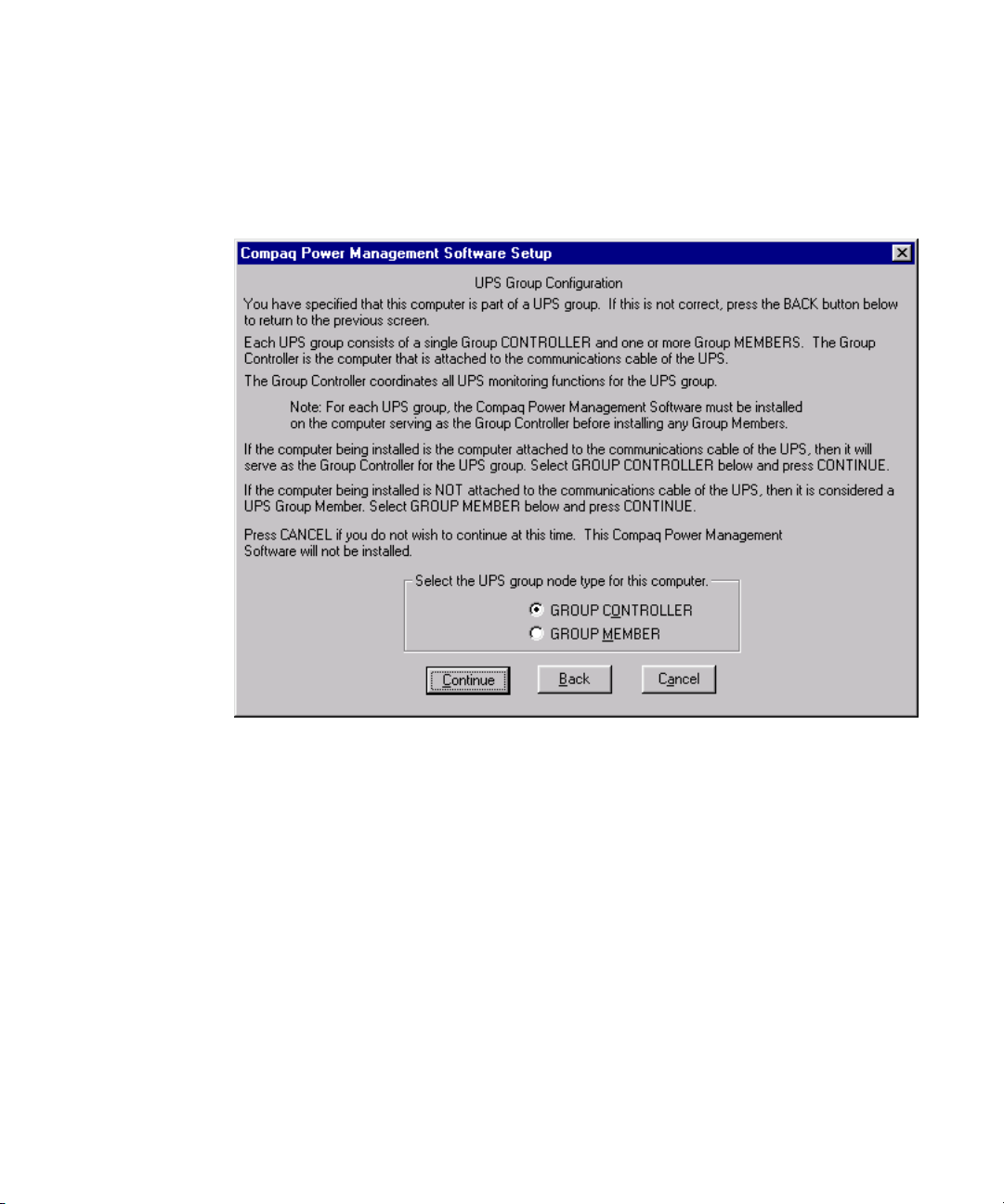
2. If the computer on which the Agent is being installed is the one connected to the
UPS using the communications port, click GROUP CONTROLLER, click
Continue, and then proceed to step 3. For all other computers in the UPS Group,
click GROUP MEMBER, click Continue and proceed to step 4.
Figure 2-2. UPS Group Configuration window
Page 21
Installation 2-9
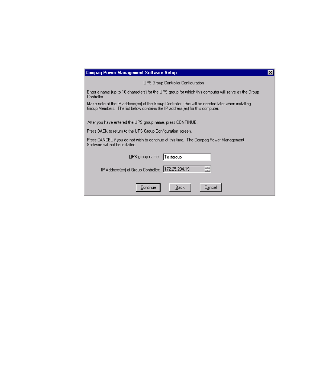
3. In the UPS Group Controller Configuration window, enter a name for
the UPS Group (this name appears in the Console for easier
identification) and click Continue.
Figure 2-3. UPS Group Controller Configuration window
Page 22

2-10 Compaq Power Products Software Reference Guide
4. On the UPS Group Member window, do one of the following:
G UNIX: Enter the host name of the Group Controller and press the
Continue button.
G Other operating systems: Type the IP address of the Group
Controller and press the Continue button.
Figure 2-4. UPS Group Member Configuration window
NOTE: On SCO OpenServer and UNIXWare systems without other means of name
resolution, the IP address and Hostname of the group Controller must be added to the
/ETC/HOSTS file before it can be entered during the Agent installation. The HOSTS file
may be changed using a text editor (OpenServer and UNIXWare 7.x) or with the Internet
Setup Utility (UNIXWare 2.x).
All members of the UPS Group may be managed via the CPM Console for the
UPS group Controller. Each member should be assigned to the load segment
to which it is attached by using the Attachments feature (described in
Chapter 3, “Operation”). After load segment assignment, individual settings
may be configured for each computer and/or load segment.
Page 23

IMPORTANT: Since the group Controller is responsible for managing the shutdown of all
systems in a power failure, it must have the longest shutdown time of all the systems in
the UPS Group. Also, since group operations depend on network communications, any
powered network infrastructure items (such as hubs, switches, and routers) necessary for
network communications must be connected to the UPS or other fail-safe power source
with runtime at least equivalent to the shutdown time of the Group Controller.
Accessing the Software
To access the Compaq Power Management software features, double-click the
desired device in Compaq Insight Manager. Click Recovery, then click UPS.
The following screen appears:
Installation 2-11
Figure 2-5. Main CPM Console window
NOTE: Throughout this guide, “Accounting” is the name used for the server.
The Main CPM Console window displays an overview of the Compaq Power
Management software options. A colored border around Status indicates the
overall status of the Compaq Power Management software system, as follows:
■ A green border indicates all the messages within the system are normal.
■ A yellow border indicates there is a System Degraded message.
Investigate as soon as possible.
■ A red border indicates there is a System Failure message. Investigate
immediately.
Page 24
2-12 Compaq Power Products Software Reference Guide
Button Description
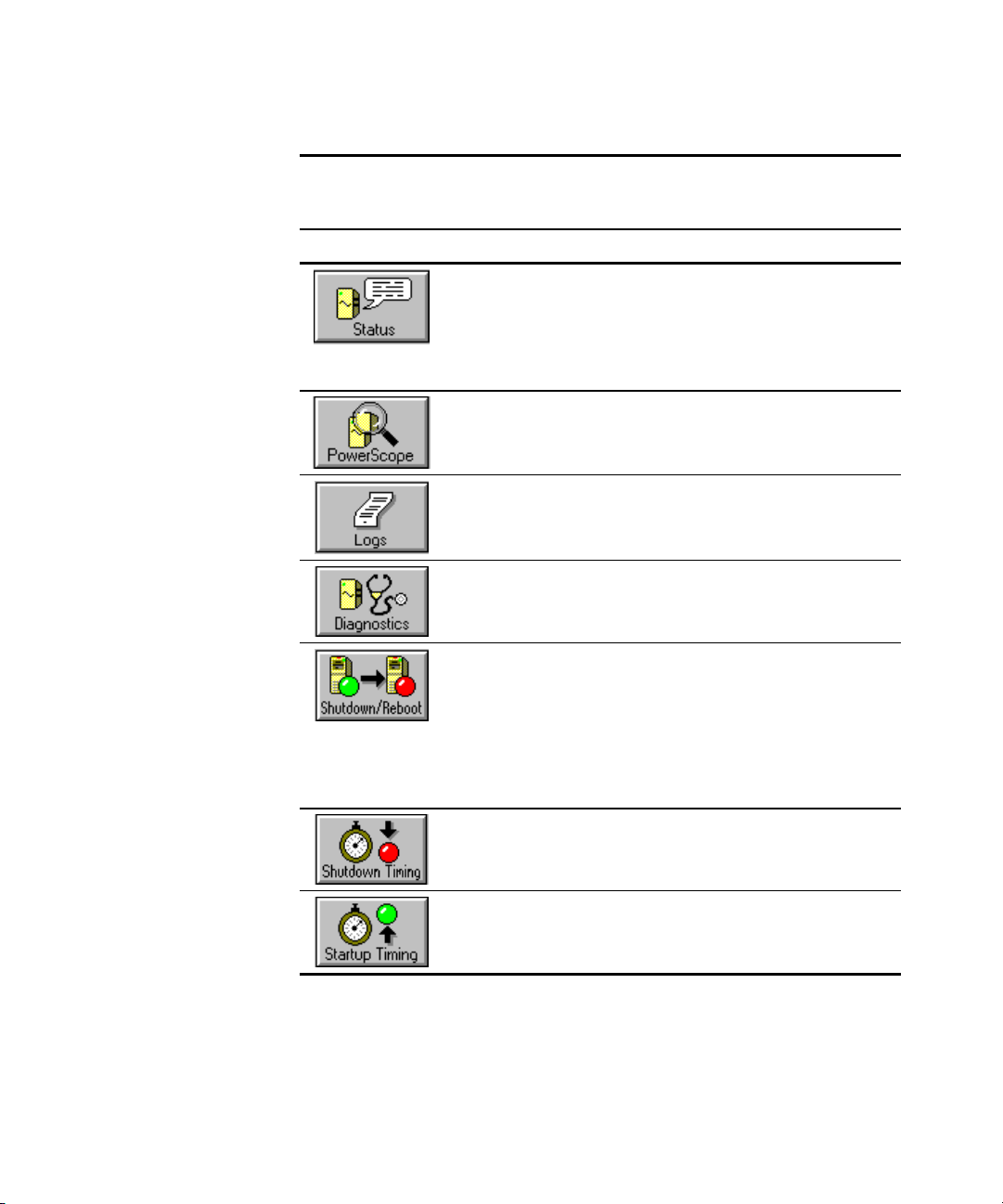
Status Click to view color-coded information on
PowerScope Click to view a dynamic, functional block
Logs Click to access power event and battery
Diagnostics Click to start diagnostics, placing the UPS on
Table 2-1
Screen Button Descriptions
system elements, including UPS
communications, UPS operational status, utility
power, battery charge, utility ground fault
detection, inverter power, and UPS overload
detection.
diagram of power from the source, throughout
the UPS, and out to the load.
management logs that provide a history of
significant system events.
battery for several seconds while the UPS
verifies battery and internal circuit operation.
Shutdown/Reboot Click to set shutdown/reboot options. Pick from
the following:
■ RebootReboots the system now.
■ PermanentShuts down the system now.
■ TimedShuts down the system and
reboots at a specified time.
Shutdown Timing Click to set the parameters for server and load
segment shutdown timing.
Startup Timing Click to set a restart delay for a load segment
that you want to start after the server or
computer regains power.
continued
Page 25
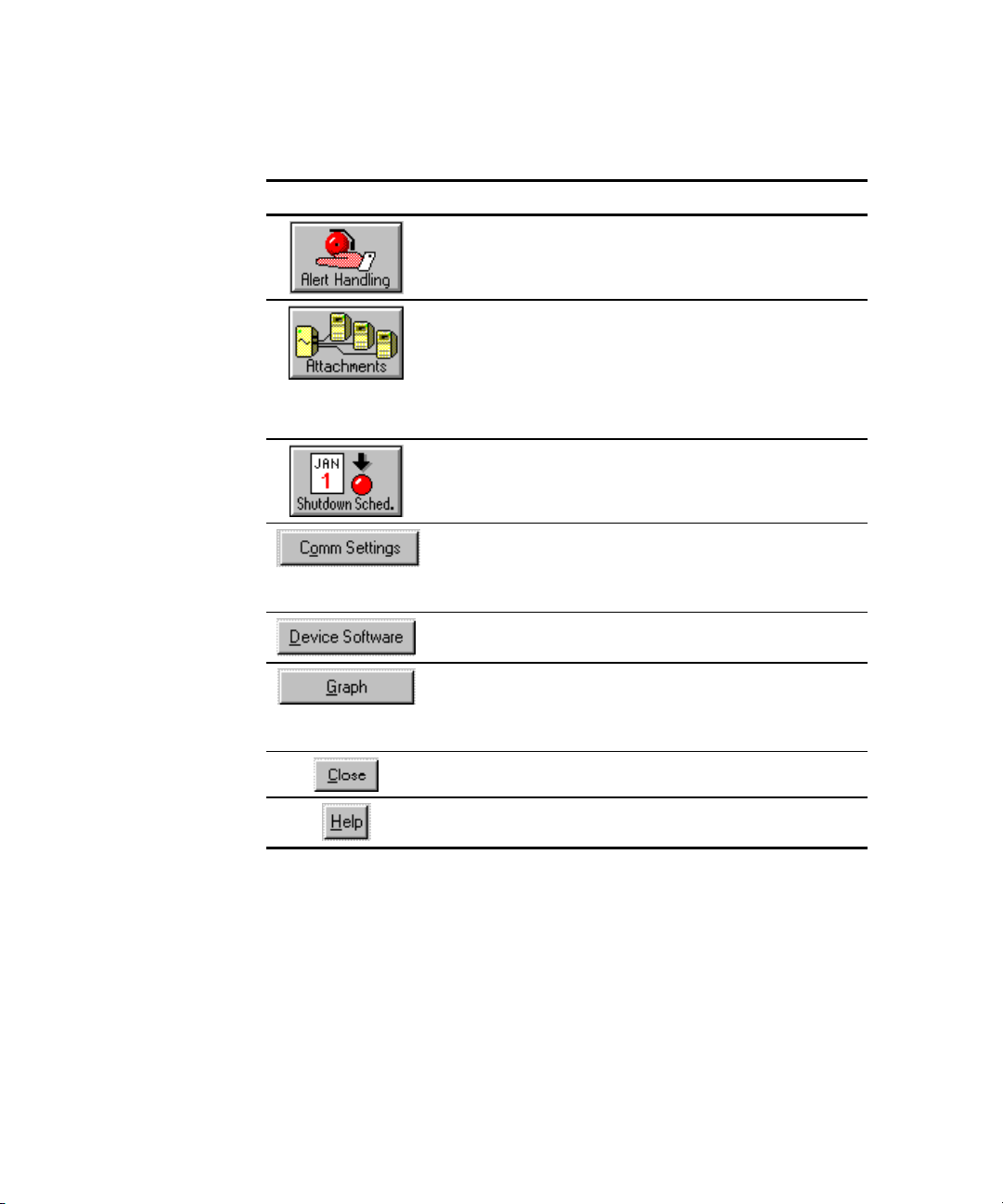
Table 2-1
Screen Button Descriptions
Button Description
Alert Handling Click to change message text, or to cause the
Attachments Click to configure your UPS load segments,
Installation 2-13
continued
system to execute a command or notify users if
a certain alert situation prevails.
enabling individual control of load segments.
Set a server to a particular load segment or the
entire load.
IMPORTANT: This must be done first, before
other parameters can be set.
Shutdown
Sched.
Comm Settings Click to open the Communications Port Setup
Device Software Click to display the Device Software window for
Graph Voltage
Parameters
Close Click to close the active window.
Help Click to access Help from the active window.
Click to shut down and restart your computer
automatically at set times.
window to configure the software for the
computer communications port being used for
communications with the UPS.
the UPS subsystem.
Click to graph different parameters in a time
graph. Draw a history graph of input/output
voltages, battery voltage, output frequency and
output load.
Page 26

Compaq Power Management software is divided into three basic features:
■ Information
■ Operations
■ Customization and Configuration
This chapter describes how to use each of these features.
Using the Information Features
Chapter 3
Operation
The Status, PowerScope, and Logs windows display current or historical
information about the status of the UPS.
Page 27

3-2 Compaq Power Products Software Reference Guide
Status Window
The Status function provides a color-coded overview of the system
(normal/degraded/failed) in the Status window within Compaq Insight
Manager.
The Status window provides color-coded information on system elements,
including UPS communications, UPS operational status, utility power, battery
charge, utility ground fault detection, inverter power, and UPS overload
detection.
Figure 3-1. Status window
Use the Status window to review the system operational and communication
status. Indications are color-coded as follows:
■ A green dot before a status category indicates normal operation.
■ A yellow dot before a status category indicates the system is degraded.
Investigate as soon as possible.
■ A red dot before a status category indicates a system failure. Investigate
immediately.
Page 28

Operation 3-3
The Status window provides the UPS model, part number, serial number, and
firmware revision, and the following status information:
■ UPS communications
■ UPS operational status
■ Utility power (online-interactive)
■ Battery charge
■ Backfeed relay
■ Battery
■ Utility ground fault detection
■ Inverter power
■ UPS overload detection
Select the Status arrows to scroll through the list.
Page 29

3-4 Compaq Power Products Software Reference Guide
PowerScope Window
The PowerScope display is a dynamic, functional block diagram of power
from the source
voltages are color-coded. Available runtime is given in minutes. The load
percentage, a measure of the capacity of the UPS currently being used, is
displayed in the Load% value box.
through the UPSand out to the load. UPS input and output
Figure 3-2. PowerScope window
Page 30

Operation 3-5
The PowerScope window provides the following information:
■ Volts In—Located on the left side of the PowerScope window, the
Volts In section shows the voltage of utility power and a colored bar.
The color describes the power situation, either as acceptable (green),
near range limits (yellow), or out-of-range (red).
In case of extreme undervoltage or overvoltage, an alarm sounds and the
UPS switches to UPS battery power. If the colors on the display show
the input power to be in the yellow or red range, save work and close
files immediately, then resolve the problem.
If the situation persists, contact the local utility company.
■ Volts Out and Load%—Located on the right side of the PowerScope
window, the Volts Out section shows the voltage of output power to the
system, and a colored bar. The color describes the power situation,
either as acceptable (green), near range limits (yellow), or out-of-range
(red).
Use the Volts Out information and the Load% value to evaluate the
utilization of the UPS.
❏ If the Load% value is in the yellow or red range, power
requirements demand a UPS with a higher load capacity.
❏ If the Load% value is in the red range, the UPS is overloaded and a
computer shutdown will occur in one minute or less.
❏ If the Load% value is in the green range, the UPS is operating
safely within the load range of the UPS.
NOTE: If the Load% value consistently exceeds 80 percent, consider adding another UPS.
CAUTION: An extended red value is a cause for concern. A system shutdown
will occur in one minute or less. Save work and close files immediately, then
resolve the problem.
■ Buck and Boost—A proprietary line regulation process used when an
overvoltage or undervoltage situation occurs in the UPS. Undervoltage
is boosted to increase the voltage, and overvoltage is bucked to reduce
the voltage, thus lessening reliance on the battery.
■ Bypass Circuitry—A feature of some UPS units that causes the system
load to be powered directly from the UPS input.
Page 31

3-6 Compaq Power Products Software Reference Guide
■
EBM—The abbreviation for Enhanced Battery Management, a
proprietary, microprocessor-based system for monitoring and managing
UPS batteries, with such features as quick recharging, doubled battery
life, and up to 60 days of advanced warning before the batteries need
replacement. EBM prevents overcharging and accelerated battery aging
when not constantly charging the battery.
■ Filter—The UPS component that prevents corruption of system data by
ensuring that transients and high frequency noise are reduced or
eliminated.
■ Inverter—The UPS component that converts DC from the UPS battery
to AC for powering the system.
■ Charger—This system detects the actual charge state of the battery and
provides a full charge or a float (intermittent) charge, only when
required.
■ Run Time—Maximum battery time available to support the system
until inverter shutdown, based on current load and UPS conditions.
Page 32
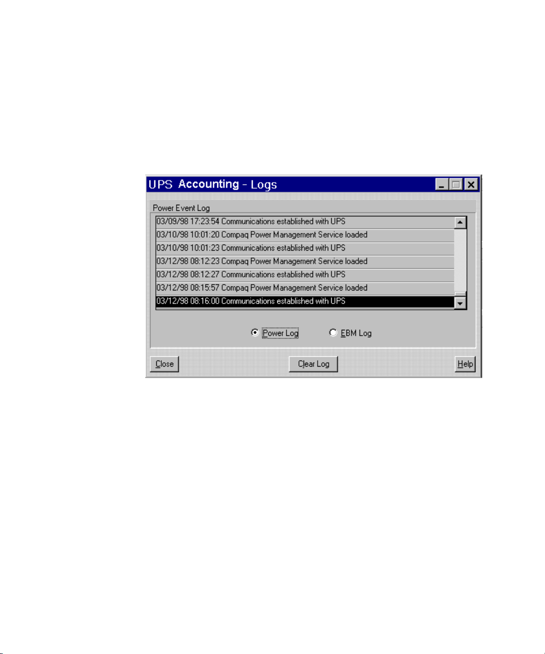
Logs Window
The Power Event Enhanced Battery Management (EBM) Log provides a
history of significant system events that can be used for problem detection and
resolution.
Use the Logs window to access the Power Log and the Enhanced Battery
Management (EBM) Log.
Operation 3-7
Figure 3-3. Logs window
The Power Log is a record of significant power events, including power
outages, low battery and overload conditions, hardware self-test results,
software loads and unloads, and serial communication connections and
failures.
Page 33
3-8 Compaq Power Products Software Reference Guide
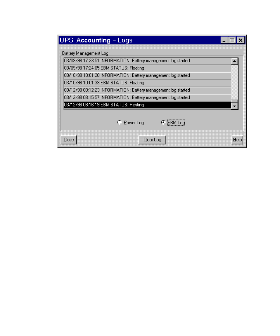
Figure 3-4. Enhanced Battery Management (EBM) Log window
The EBM Log records changes in the EBM status. Records include log started,
charging, discharging, floating (that is, the battery is receiving only a nominal
charge), log stopped, log cleared, and resting (that is, the battery is receiving
no charge).
Click Clear Log to delete all log entries, leaving a single entry showing the
date and time the log was cleared.
Toggle from Power Log to EBM Log by clicking Power Log or EBM Log.
Page 34
Using the Operations Features
The Diagnostic and Shutdown/Reboot windows provide a way to facilitate
UPS maintenance.
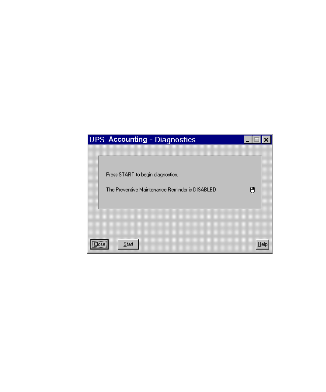
Diagnostics Window
Use the Diagnostics window to start a self-test of the UPS. The self-test places
the UPS on battery for several seconds. During this time, the UPS verifies the
battery and internal circuit operation. The UPS Diagnostics window displays
the current testing status.
Operation 3-9
Figure 3-5. Diagnostics window
To perform a UPS self-test, press the Start button. To close the window
without starting a self-test, click the Close button.
Page 35
3-10 Compaq Power Products Software Reference Guide
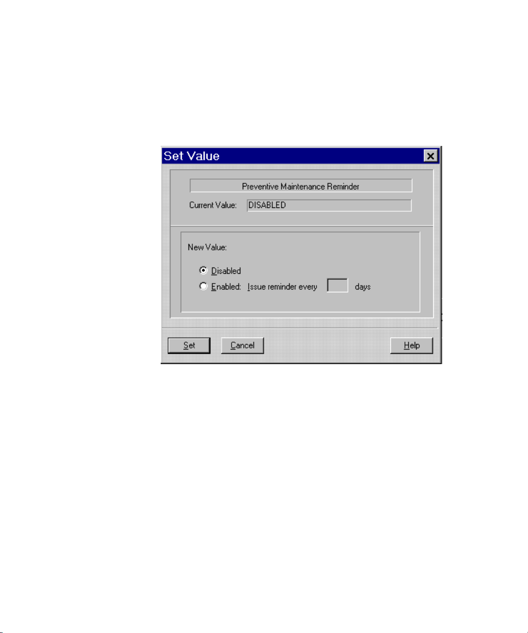
Setting the Preventative Maintenance Alarm
The Preventative Maintenance Alarm can be set to remind the user to run
diagnostics at a predetermined interval. To access the Preventative
Maintenance Alarm settings, right-click the mouse icon on the Diagnostics
window, then press the Set button.
Figure 3-6. Preventative Maintenance reminder window
To disable the alarm, click Disabled, then press the Set Button.
To enable the alarm, click Enabled, then type a time period. This must be in
increments of 30 days, for example 30, 60, 90, and so on, then press the Set
Button.
Page 36

Shutdown/Reboot Window
Use the UPS Shutdown/Reboot window to shut down the UPS. Compaq
Power Management software can shut down the UPS with one of the
following three startup options:
■ RebootAn immediate reboot can be performed.
■ PermanentThe shutdown may be permanent (powers off the unit)
until the UPS is restarted manually.
■ TimedThe startup can be timed for any user-specified interval.
Operation 3-11
Figure 3-7. Shutdown/Reboot window
If a system shutdown is necessary, the Compaq Power Management software
saves only named files.
CAUTION: To avoid data loss if a power failure occurs, name any new files as
soon as they are opened.
For applications with automatic saving capability, set the Autosave time to a
value less than the power failure countdown time.
Page 37

3-12 Compaq Power Products Software Reference Guide
To shutdown the system:
1. To reboot the system immediately after shutdown, click Reboot. For a
system shutdown until the UPS is manually restarted, select Permanent.
For a system shutdown of a specific length, select Timed, then type a
time period.
2. Press the Shutdown button.
CAUTION: Exercise extreme caution in selecting the Shutdown button. The
result is the start of an immediate, irreversible shutdown of the UPS and all
attached equipment. If a server is shut down, all users on the server are forcibly
logged out, and work in progress may be lost.
Page 38
Using the Customization and Configuration Features
Use the features described in the following sections to configure shutdown
timing, to set multiple device support, and to initiate alarms and commands in
the event of an alert situation.
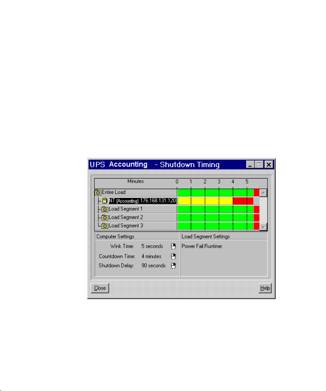
Shutdown Timing Window
The shutdown timing for a Compaq server is specified in terms of Wink Time,
Countdown Time, and Shutdown Delay to allow for a prioritized, customized
system shutdown. The shutdown of non-essential equipment can be
programmed for any interval following a commercial power failure, freeing
battery capacity for critical servers and other equipment.
Operation 3-13
Figure 3-8. Shutdown Timing window
Page 39

3-14 Compaq Power Products Software Reference Guide
Use the Shutdown Timing window to set the parameters for a computer
shutdown, and to set a power failure runtime for non-essential peripherals on a
load segment using the following controls.
Shutdown timing is the sum of Wink Time, Countdown Time, and Shutdown
Delay.
■ Computer Settings
G Wink Time—The interval between an alert situation and the
transmission of an alert message from the system to the user. This
interval can be extended to reduce nuisance messages or shortened to
reduce reliance on the battery. The default is 5 seconds.
G Countdown Time—The time in minutes after the end of Wink Time
that the system waits before starting a shutdown sequence. This
interval allows time to finish work and save files. Each minute, the
user is informed of the time remaining until shutdown. The default
value is 5 minutes.
G Shutdown Delay—The time in seconds from when the software
begins to shut down the system until the power from the UPS shuts
off. This interval allows the system to log off servers and users,
terminate any applications that may be running, and close all files in
the file system. The default value is 90 seconds.
■ Load Segment Setting
G Power Fail Runtime—The amount of time in seconds between the
shutdown message and actual shutdown. A value of Automatic
means that the load segment will run until the computer shuts down.
A value of Infinite means the load segment will run until the UPS
shuts down due to a low battery. Set a Power Fail Runtime for a
faster shutdown of non-essential peripheral equipment.
NOTE: If configuring a UPS Group shutdown time, the shutdown time for the UPS Group
Controller cannot be set at a value less than the shutdown time for any Group Member. To
reduce the shutdown time for the UPS Group Controller to a value less than the shutdown
time for a Group Member, the shutdown time for the Group Member must first be
reduced.
Page 40

Operation 3-15
The following items should be carefully considered before utilizing Shutdown
Timing:
■ The length of battery protection increases as the load on the UPS
decreases.
■ After a power outage recovery, another outage could occur before the
UPS batteries fully charge. For a more robust system fault tolerance, set
the Countdown Time to a value small enough to allow battery reserve
for at least two shutdowns.
■ Do not allow the UPS to shut off until all applications are terminated
and all files in the system are closed. Set the Shutdown Delay to a value
large enough to ensure that the software has time to shut down a
worst-case computer environment.
■ If a system shutdown is necessary, the Compaq Power Management
software saves only named files. To avoid loss if a power failure occurs,
name any new files when they are opened.
Configuring Computer Shutdown Timing
1. In the Shutdown Timing window, highlight a server or computer icon.
2. Right-click the mouse icon to the right of the setting to change, then
click Set.
3. In the Set Value window, set values for Wink Time, Countdown Time,
and Shutdown Delay.
4. Press the Set button.
Configuring Load Segment Shutdown for
Non-essential Peripherals
A load segment is a portion of the load, or electrical device(s) to which power
is delivered.
1. In the Shutdown Timing window, highlight the load segment to which
non-essential peripherals are attached.
2. Right-click the mouse icon to the right of the Power Fail Runtime field,
then press the Set button.
3. Set a new value in minutes.
4. Press the Set button.
Page 41

3-16 Compaq Power Products Software Reference Guide
Startup Timing Window
Startup Timing configuration is an option for users with UPS models that
support more than one load segment. Use the UPS Startup Timing window to
set a restart delay for the load segment startup order by priority (that is, most
critical load segments to regain power before the less critical load segments).
Figure 3-9. Startup Timing window
Setting a Restart Delay
1. Select a load segment in the Startup Timing window.
2. Right-click the mouse icon to the right of Startup Delay, then press the
Set button.
Page 42

Figure 3-10. Restart Delay Configuration window
Operation 3-17
3. Type the new value in the Restart Delay field.
4. Press the Set button.
Page 43

3-18 Compaq Power Products Software Reference Guide
Alert Handling Window
Use the Alert Handling window to change the text of a Compaq Power
Management (CPM) message, or to cause the system to execute a command or
send E-mail or a broadcast message to users if a certain alert situation prevails.
A Disabled value in the E-Mail, Execute Command, and Users To Broadcast
edit fields means the function is not in use for the selected message.
NOTE: A second RS-232 communications port is required if the modem feature is used.
Figure 3-11. Alert Handling window
For a complete list of all alert message texts, see Appendix A, “Alert Message
Texts.”
To view the current settings for a message, click the arrows to scroll through
the list; then select a message field once to highlight the field and display the
current settings.
Page 44

Configuring Alert Handling
1. Right-click the mouse icon next to the Message Text, E-Mail, Execute
Command, or Users To Broadcast field in the Alert Handling window,
then press the Set button. The Alert Handling window reopens for
editing.
Operation 3-19
Figure 3-12. Alert Handling editing window
2. Perform one or more of the following tasks:
G In the Message Text field, type new text for the highlighted message.
G Click the box next to E-Mail, and then type the address where the
selected alert should be sent.
G Click the box next to Execute Command, then type a command to be
executed when the selected alert occurs.
G Under the Broadcast to Users field, select the button for the
appropriate users.
3. Press the Set button to save settings or the Cancel button to revert to the
previous settings and return to the Alert Handling window.
Page 45

3-20 Compaq Power Products Software Reference Guide
4. In the Alert Handling window, select the Close button to save the
settings or the Reset Defaults button to reset the default settings.
Attachments Window
IMPORTANT: The first time Compaq Power Management software is run, the server must
be assigned to a load segment (before the UPS knows where the server resides). This
must be done before any other parameters can be set.
The attachments window allows assignment of the server to load segments,
otherwise individual control of all load segments is not possible.
Load shedding is the ability to divide the total load into segments and to start
and stop each load segment individually. Use the Attachments window to
configure the UPS load segments, enabling load shedding. If load shedding is
not enabled, the computer and all peripherals attached to the UPS shut down at
the end of the shutdown delay and restart immediately after a power failure,
when power is restored.
Use the shutdown schedule window (explained later in this chapter) to set a
shorter Power Fail Runtime for non-essential peripherals. Use the UPS Startup
Timing window to delay the restart of non-essential peripherals.
To enable load shedding, attach the computer and peripheral load segment
groups to the rear of the Compaq UPS, and configure the loads in the
Attachments window. For detailed information on the load segment
configuration, refer to the documentation included with the UPS kit.
Page 46

Configuring Load Segments in the Software
1. Right-click Load Segment/Computer List, then press the Set button.
The Computer/Receptacle Attachments configuration window is
displayed.
Operation 3-21
Figure 3-13. Attachments window
Page 47

3-22 Compaq Power Products Software Reference Guide
Figure 3-14. Computer/Receptacle Attachments configuration window
2. Press the Move Up and Move Down buttons to place the icon under the
load segment to which the computer is physically attached.
3. Press the Set button to save changes and return to the Attachments
window.
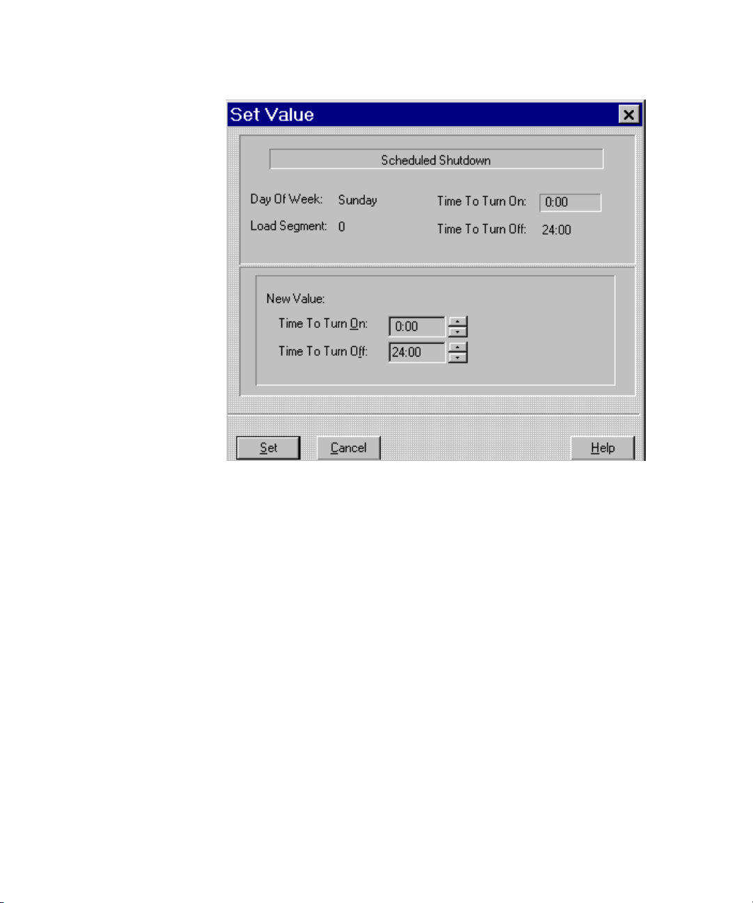
Shutdown Schedule Window
Use the shutdown schedule window to shut down and restart the computer
automatically at set times each day. Scheduled shutdowns and restarts may be
specified for each day of the week.
Page 48

Shutting Down a Load Segment
on a Regular Basis
Figure 3-15. Shutdown Schedule window
1. In the Day of Week list, select the desired day of the week.
Operation 3-23
2. In the Shutdown Schedule window, highlight a load segment.
3. Right-click the mouse icon next to Power Schedule, then click Set. The
Scheduled Shutdown timing window is displayed.
NOTE: To shut down and restart the system one time only, click Shutdown/Reboot from
the Main CPM Console window.
Page 49
3-24 Compaq Power Products Software Reference Guide
Figure 3-16. Scheduled Shutdown timing window
4. Under New Value, select a new Time To Turn On and Time To Turn
Off.
5. Click Set to save changes.
Page 50

Significant Power Events
If a power failure or other significant power event occurs, the system reacts as
follows:
■ In Windows NT 4.0 and Windows 2000 environments, the CPM system
tray icon changes color and the Compaq Power Management software
window opens automatically to display the most recent status messages.
■ In an OS/2 environment, the CPM desktop icon changes color, beeps,
blinks, and advances to the window foreground. Double-click the icon
to open the Compaq Power Management software window to review the
most recent status messages.
Chapter 4
Troubleshooting
■ In Unix and NetWare environments, alerts appear at the server console
command line.
If utility power is lost, the Agent begins an orderly shutdown of the system.
The Agent saves work-in-progress and logs all significant power and battery
events.
Page 51

4-2 Compaq Power Products Software Reference Guide
For situations other than power outages, note the following:
■ If a modem has been attached to the system, the modem must be
configured in Compaq Insight Manager to enable the paging or alert
messaging function.
■ The UPS must be attached to the server with the correct
communications cable. Refer to the user guide supplied with the UPS.
■ The communications cable from the UPS to the server must be attached
to the communications port as configured in the Compaq Insight
Manager software for the UPS.
Page 52

Error Messages
Specific troubleshooting items that may occur during operation or during setup
of the UPS product are listed in the following table.
Type of Error Possible Cause Solution
Troubleshoo ting 4-3
Table 4-1
Error Messages
Communications. Compaq Insight Manager is
configured for a different
communications port than the
computer interface cable.
Computer interface cable is not
connected, secure, or properly
installed.
Configuration File. Installation unsuccessful. Reinstall.
Low Battery. Low battery voltage. Replace battery. Refer to the
Power Failure. No power. Verify UPS connection to a
Unable to Contact. Software not running. Start CPM Agent on the server.
No message when simulating a
power failure.
NetWare server is getting the
following errors: ‘UPS is not
responding.’
Compaq Insight Manager is
configured for a different
communications port than the
computer interface cable.
Interface cable is not connected,
secure, or properly installed.
The NetWare server has the old
CPQUPS driver and CPQUPSSA
agent loaded. This driver is for a
previous version of Compaq UPS
products.
Reconfigure the
communications port in
Compaq Insight Manager.
Reinstall communications cable
securely.
UPS user guide for instructions.
working outlet and that UPS is
powered on.
Reconfigure the
communications port in
Compaq Insight Manager.
Reinstall communications
cable.
The server should be updated
with the latest CPM version.
continued
Page 53

4-4 Compaq Power Products Software Reference Guide
Table 4-1
Error Messages
continued
Type of Error Possible Cause Solution
The UPS has a RED light on LED
04, and will not charge. The UPS
was previously working fine, and
either experienced a real power
failure, or was tested by the
customer.
The Diagnostics and
Shutdown/Reboot icons are
grayed out on the Compaq
Insight Manager workstation
console.
When attempting to view UPS
information in Compaq Insight
Manager for a server that is a
UPS Group Member, Compaq
Insight Manager will give an error
‘unable to communicate with
UPS.’ The Group Controller can
retrieve UPS information without
difficulty, and the Group
Members are communicating
with the Group Controller.
NetWare UPS Group Member can
not establish connection with the
Group Controller using TCP/IP.
This will only occur when a new
model UPS has had the input
voltage disconnected while the
UPS was being monitored with
previous versions of Compaq
driver/agents, either NetWare or
Windows NT 4.0.
The Diagnostics and
Shutdown/Reboot operations
require SNMP ‘SET’ rights.
All members of a UPS Group
must be managed using either all
IP or all IPX.
The TCP/IP address of the Group
Controller may not have been
entered correctly when running
CPQSETUP.NLM.
The server should be updated
with the latest CPM version.
Verify the SNMP Control
community string, and make
sure that under the server
device setup in Compaq Insight
Manager, the control
community string is used.
Change the UPS Group Member
server setup in Compaq Insight
Manager so that it is using the
same protocol as the Group
Member.
NOTE: NetWare can use either
TCP/IP or IPX to communicate
with a Group Controller.
Microsoft NT can only use IP.
Unload all the CPM agents, then
re-run CPMSETUP.NLM. When
asked to enter the IP address of
the Group Controller, enter the
address without using leading
zeros.
continued
Page 54

Table 4-1
Error Messages
Type of Error Possible Cause Solution
Troubleshoo ting 4-5
continued
UPS Group Member can not
establish connection with the
Group Controller using IPX.
‘Error copying files’ when
running CPMSETUP.NLM on a
NetWare server.
Note: Contact your system administrator for all other messages.
The IPX address of the Group
Controller may have not been
entered correctly when running
CPQSETUP.NLM.
The appropriate directory
structure is not available for
CPMSETUP.NLM to copy
configuration files from during
setup.
Unload all the CPM Agents, then
re-run CPMSETUP.NLM. When
asked to enter the IPX address
of the Group Controller, enter
the ‘Controller Network’
hexadecimal number using
CAPS for A through F. Enter the
‘Controller Address’ with all the
leading zeros.
CPMSETUP.NLM requires that
the entire contents of the
directory structure be in place,
so it can copy configuration
files to SYS:SYSTEM. There
should be directories named
CONTROLR, MEMBER, and
STANDALON. Each of these
directories contains three files,
CPMIP.NLM, CPMIPX.NLM, and
UPSBASE.NLM.
Page 55

Appendix A
Alert Message Texts
The Alert Handling window is used to change the text of a message, or to
cause the system to execute a command, send e-mail, or a broadcast message
to users if a certain alert situation prevails. A Disabled value in the E-Mail,
Execute Command, and Users To Broadcast edit fields means that function
is not in use for the selected message. A list of all message texts is provided in
the following table.
Table A-1
Alert Message Texts
Number Message Text
0 $MACHINE is on battery shutdown in $MINUTES mins
1 $MACHINE will shut down in 1 min
2 $MACHINE shutdown has been cancelled
3 $MACHINE is now shutting down
4 Unable to contact UPS group controller
5 Contact with UPS group controller established
6 Compaq Power Management Service loaded
7 Compaq Power Management Service unloaded
8 Time to run preventive maintenance
9 Communications port is unavailable
continued
Page 56

A-2 Compaq Power Products Software Reference Guide
Table A-1
Alert Message Texts
Number Message Text
10 Communications failure with UPS
11 Communications established with UPS
12 Abnormal operation
13 Abnormal operation resolved
14 Utility power failure
15 Utility power failure resolved
16 Low battery
17 Low battery resolved
18 Bypass condition
19 Bypass condition resolved
20 Battery disconnect
21 Battery disconnect resolved
22 Backfeed contact failure
continued
23 Backfeed contact failure resolved
24 Abnormal battery discharge
25 Abnormal battery discharge resolved
26 Battery fuse failure
27 Battery fuse failure resolved
28 Abnormally low battery
29 Abnormally low battery resolved
30 DC overvoltage
31 DC overvoltage resolved
32 Bypass fuse failure
33 Bypass fuse failure resolved
34 Abnormal battery charge
35 Abnormal battery charge resolved
continued
Page 57

Table A-1
Alert Message Texts
Number Message Text
36 Battery failure
37 Battery failure resolved
38 Cabinet overtemperature
39 Cabinet overtemperature resolved
40 High utility frequency
41 High utility frequency resolved
42 Low utility frequency
43 Low utility frequency resolved
44 Utility ground failure
45 Utility ground failure resolved
46 Inverter fuse failure
47 Inverter fuse failure resolved
48 Inverter overvoltage
Alert Message Texts A-3
continued
49 Inverter overvoltage resolved
50 Inverter overtemperature
51 Inverter overtemperature resolved
52 Inverter undervoltage
53 Inverter undervoltage resolved
54 Inverter power off
55 Inverter power off resolved
56 Oscillator failure
57 Oscillator failure resolved
58 UPS overload
59 UPS overload resolved
60 Rectifier power off
61 Rectifier power off resolved
continued
Page 58

A-4 Compaq Power Products Software Reference Guide
Table A-1
Alert Message Texts
Number Message Text
62 Rectifier fuse failure
63 Rectifier fuse failure resolved
64 Rectifier overtemperature
65 Rectifier overtemperature resolved
66 Static switch overtemperature
67 Static switch overtemperature resolved
68 Disabled UPS condition
69 Disabled UPS condition resolved
70 High utility voltage
71 High utility voltage resolved
continued
Page 59

Compaq UPS Options
Compaq offers several UPS options to further enhance UPS communication
capabilities. These options provide additional management and control
features during a power failure, and are available with minimum investment.
Compaq UPS options are available for both the Compaq option slot UPS
models and the Compaq UPS XR models.
Options for the Option Slot UPS Models
Compaq offers three UPS options for the option slot UPS models:
■ Multi-Server UPS Card (Compaq part number 123508-B21)
Appendix B
■ Scalable UPS Card (Compaq part number 123509-B21)
■ SNMP-EN Adapter (Compaq part number 347225-B21)
■ SNMP Adaptor (Compaq part number 192189-B21)
■ Six Port Card (Compaq part number 192185-B21)
NOTE: Neither the SNMP adapter P/N192189-B21 or the SNMP-EN adapter
P/N 347225-B21 are supported by CPM Software. Compaq Onlinet Centro
software is available to manage these options, and is included in the SNMP and
SNMP-EN adapter Option Kit.
Page 60

B-2 Compaq Power Products Software Reference Guide
In addition to the UPS options listed, Compaq also offers the Extended
■
Runtime Module (ERM), Compaq part number 347224-B21, for use
with the Compaq 6000 Series UPS (with two option slots). This 3U rack
option significantly expands the available battery runtime of the already
powerful 6000 Series UPS.
Compaq Multi-Server UPS Card
Figure B-1. Multi-Server UPS Card
With the Compaq Multi-Server UPS Card, system administrators can serially
connect up to three devices to a single UPS, permitting multi-protocol and
out-of-band communication for networks with multiple servers or disparate
operating systems.
For example, a business running Novell, Windows NT, and Unix servers does
not have to acquire an individual UPS for each piece of equipment. Instead,
the Multi-Server UPS Card is installed, enabling direct communication with
multiple devices even when the network is down.
By adding a single Multi-Server UPS Card to a UPS, the UPS can
independently communicate with up to three servers with different rating
systems and shutdown schedules. If the UPS has two slots, like the Compaq
6000 Series UPS, two Multi-Server Cards can be installed to enable
communication with up to five servers. Even if the network goes down, this
option enables out-of-band communication to each server, allowing a graceful
shutdown of the operating system.
Page 61

Compaq UPS Options B-3
Figure B-2. Compaq Power Management software window with option card
attached
Since the ports are pre-defined, the Startup Timing window and
Attachments window are no longer available in this configuration. The
software and hardware cannot “see” more than one server at a time, so those
options are dimmed.
IMPORTANT: Refer to the Important Safety Information guide (included with the UPS kit)
before installing this product.
NOTE: For detailed installation instructions, refer to the installation instructions supplied
with the Compaq UPS and the Compaq Multi-Server UPS Card.
Page 62

B-4 Compaq Power Products Software Reference Guide
Compaq Scalable UPS Card
Figure B-3. Scalable UPS Card
Because evolving system needs may require a higher power level to
accommodate an increased load, users can equip their UPS with the Compaq
Scalable UPS Card.
By adding the Scalable UPS Card to a UPS, one server can control up to three
UPS units with up to nine independently scheduled load segments. This allows
the user to add UPS power ratings incrementally, as power requirements grow,
with added storage and server capacity or other load availability. To Compaq
Power Management software, additional UPS units, added using the Scalable
UPS Card, appear as one virtual UPS.
Page 63

Servers
UPSs
Compaq UPS Options B-5
Primary
Server
Power
Communications
Figure B-4. Sample Scalable UPS Card configuration
IMPORTANT: Refer to the Important Safety Information guide (included with the UPS kit)
before installing this product.
NOTE: For detailed installation instructions, refer to the installation instructions supplied
with the Compaq UPS and the Scalable UPS Card.
Compaq Insight Manager and CPM software will recognize and configure the
UPS option cards automatically when installation is complete.
Page 64

B-6 Compaq Power Products Software Reference Guide
Compaq SNMP-EN Adapter
Figure B-5. SNMP-EN Adapter
The Compaq SNMP-EN Adapter provides a network interface to the UPS on
systems on which Compaq Insight Management Agents cannot be installed.
Using Compaq OnliNet Centro software, management is possible by direct
communication with the UPS, independent of connected computers.
The SNMP-EN Adapter will help you quickly ascertain if a power-related
problem exists anywhere on your network. Using the SNMP-EN Adapter
communications interface, you can virtually eliminate costly downtime due to
power outages or surges, and decrease day-to-day network management
annoyances like spontaneous rebooting, lost files and corrupted data
resulting from inconsistent power.
issues
Page 65

Option Card Combinations for the 6000 Series UPS
Two UPS Option Cards can be used simultaneously with the Compaq 6000
Series UPS for greater power management control and flexibility. The
following table describes the supported usage combinations.
Table B-1
Option Card Matrix
Compaq UPS Options B-7
Case Slot Multi-
Server
112X
212X
X
31
2
41
2
51
2
61
2
712X
NOTE: Board combinations can be used in the primary UPS only. When UPS units are
chained, additional boards can not be used in the other units.
Scalable SNMP-EN
Adapter
X
X
X
X
X
X
X
Direct Connect Result (no
Power Distribution Unit - PDU)
4 servers managing a total of 5
load segments
5 servers managing a total of 5
load segments
2 servers managing a total of 9
load segments
1 in-band connection managing
a total of 9 load segments
1 in-band connection managing
a total of 5 load segments
2 in-band connections managing
a total of 5 load segments
3 servers and 1 in-band
connection managing a total of 5
load segments
Page 66
B-8 Compaq Power Products Software Reference Guide
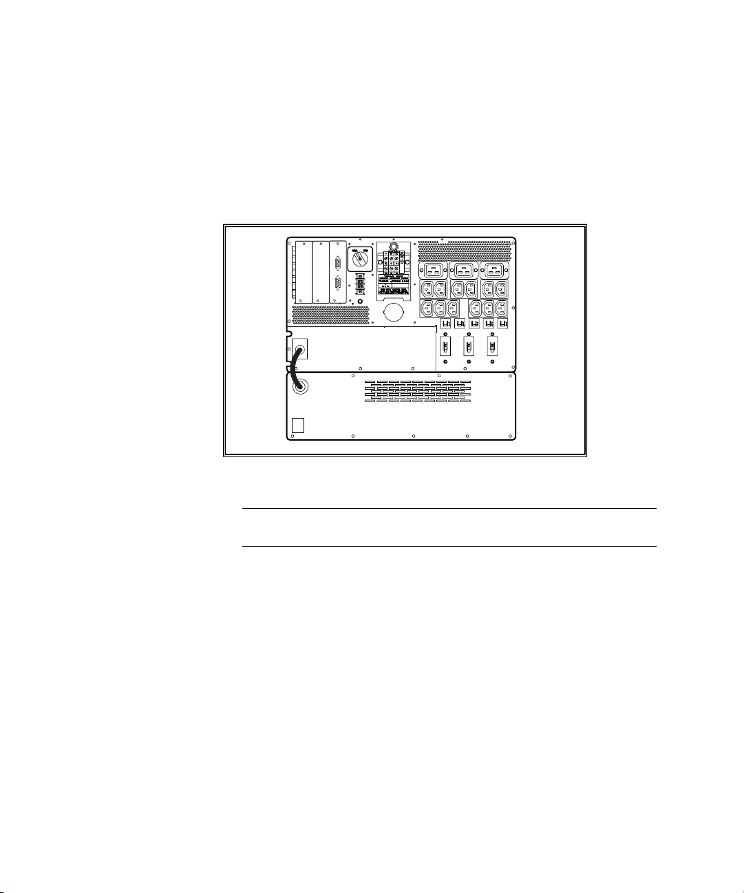
Extended Runtime Module for the 6000 Series UPS
The Extended Runtime Modules (ERM) is supported by the Compaq 6000
Series UPS. The UPS rear panel provides a power receptacle where the
modules are attached. Each ERM contains battery packs in a 3U chassis and,
by design, will extend the available UPS runtime. Up to two ERM units can
connect to each UPS.
Figure B-6. Compaq 6000 Series UPS rear panel with installed ERM
IMPORTANT: Refer to the Important Safety Information guide (included with the UPS kit)
before installing this product.
NOTE: For detailed installation instructions refer to the installation instructions supplied
with the Compaq 6000 Series UPS and the Extended Runtime Module.
Options for the UPS XR Models
Compaq offers two UPS options for the UPS XR models:
■ Six Port Card (Compaq part number 192185-B21)
■ SNMP/Serial Port Card (Compaq part number 192187-B21)
NOTE: The SNMP/Serial Port Card is not supported by CPM software. Compaq OnliNet
Centro software is available to manage this option, and is provided in the
SNMP/Serial Port Card Option Kit.
Page 67
In addition to the UPS options listed previously, Compaq also offers the
Extended Runtime Module (ERM), Compaq part number 192188-B21. This
3U rack option significantly expands the available battery runtime of UPS XR
models.
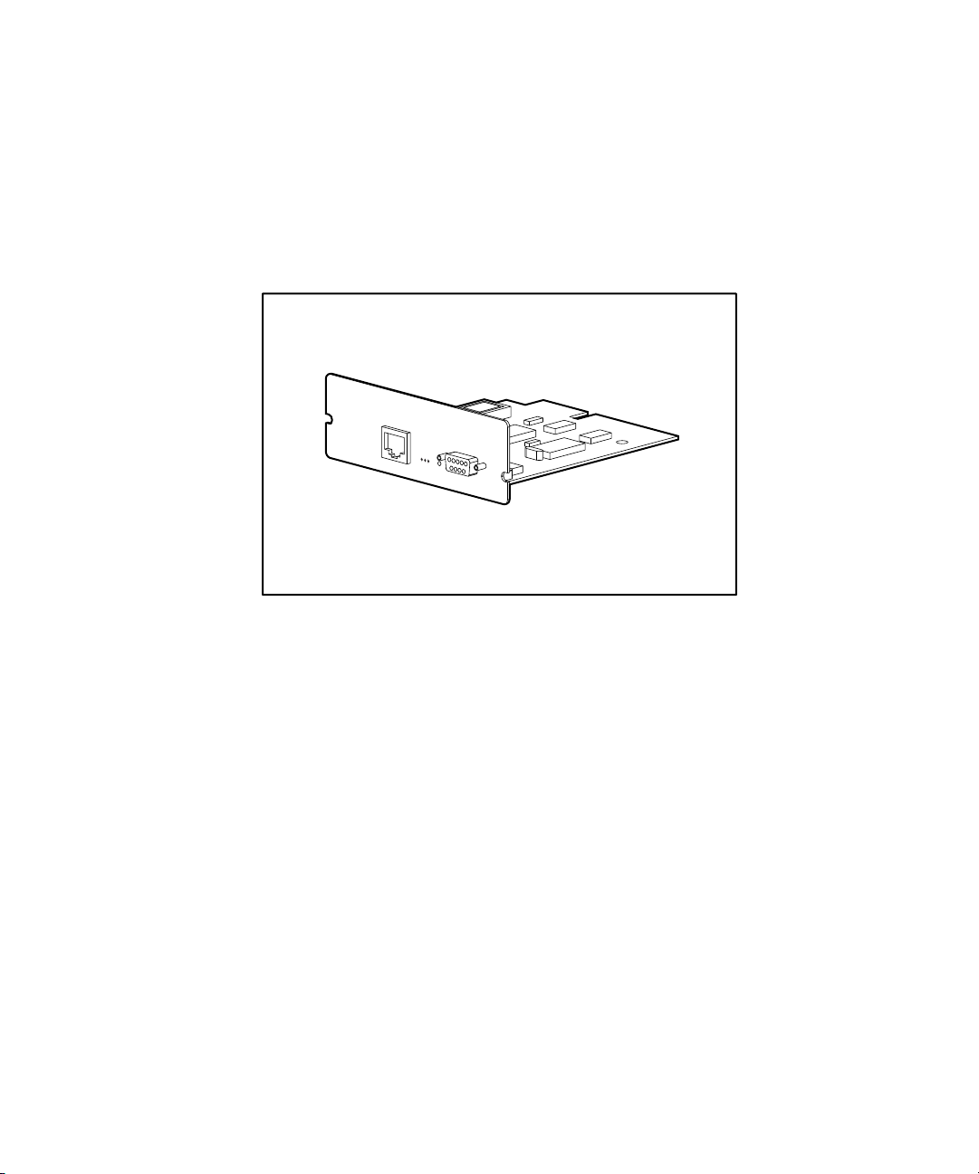
Compaq SNMP / Serial Port Card
Compaq
SNMP / Serial Port Card
1
0
Compaq UPS Options B-9
IOIOI
Figure B-7. SNMP/Serial Port Card
The Compaq SNMP/Serial Port Card provides a network interface to the UPS
on systems on which Compaq Insight Management Agents cannot be installed.
Using Compaq Onlinet Centro communications software provided with the
Option Kit, management is possible by direct communication with the UPS,
independent of connected computers.
The SNMP/Serial Port Card will help you quickly ascertain if a power-related
problem exists anywhere on your network. Using the SNMP/Serial Port Card
communications interface, you can virtually eliminate costly downtime due to
power outages or surges, and decrease day-to-day network management
annoyances like spontaneous rebooting, lost files and corrupted data
issues
resulting from inconsistent power.
Page 68
B-10 Compaq Power Products Software Reference Guide
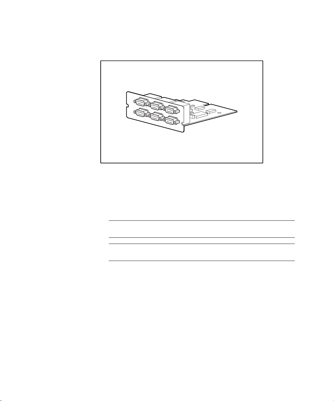
Compaq Six Port Card
5
3
6
4
Figure B-8. Six Port Card
A standard UPS can communicate directly with a single-host computer. The
Six Port Card expands the communications capability of the UPS so that a
single UPS can exchange data with up to three host computers when CPM
software is installed.
1
2
IMPORTANT: Refer to the Important Safety Information guide (included with the UPS kit)
before installing this product.
NOTE: For detailed installation instructions, refer to the installation instructions supplied
with the Compaq UPS and the Six Port Card.
Page 69
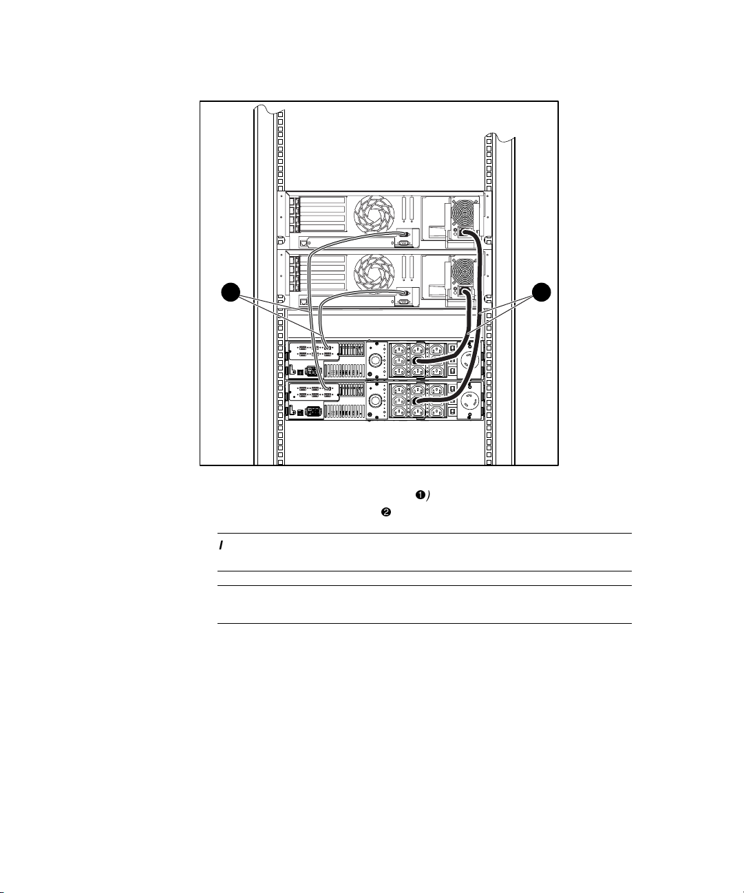
Compaq UPS Options B-11
1 2
Figure B-9. Compaq Six Port Card installed in the network using serial
communication cables from the Six Port Cards () and Power connections
from the UPS XR models to the servers ()
IMPORTANT: Refer to the Important Safety Information guide (included with the UPS kit)
before installing this product.
NOTE: For detailed installation instructions, refer to the installation instructions supplied
with the Compaq UPS and the Scalable UPS Card.
Compaq Insight Manager and Compaq Power Management software will
recognize the UPS option cards automatically when installation is complete.
Page 70
B-12 Compaq Power Products Software Reference Guide
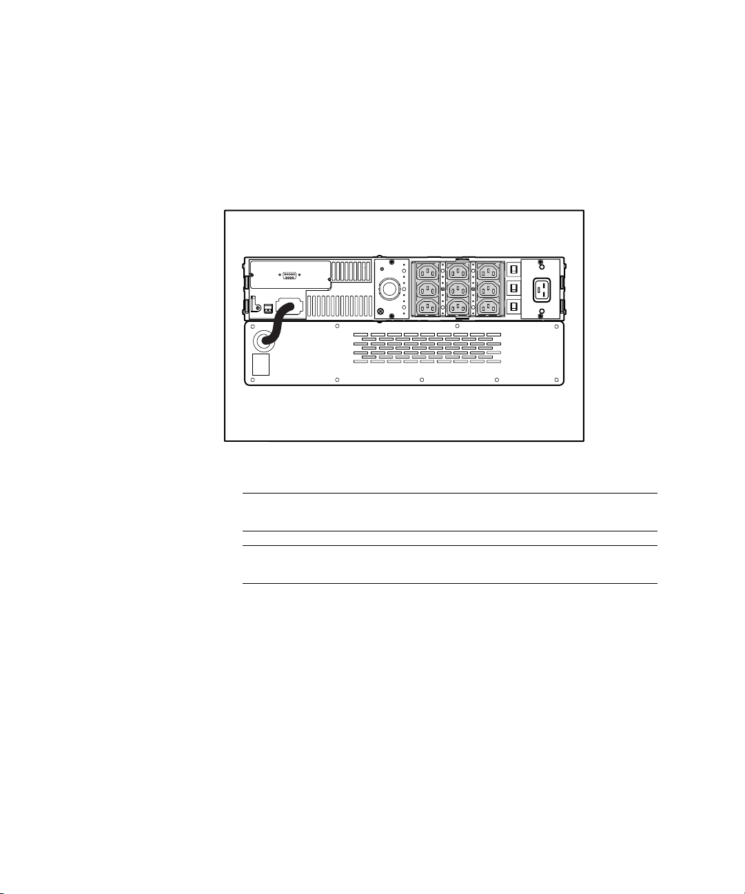
Extended Runtime Module for UPS XR Models
Compaq UPS XR models support the use of Extended Runtime Modules
(ERMs). The UPS rear panel includes a power receptacle to which the
modules attach. The XR ERM consists of a dual battery pack in a 2U chassis.
An XR ERM will extend the available UPS runtime up to 27 minutes.
Figure B-10. Compaq R3000 XR rear panel with installed XR ERM
IMPORTANT: Refer to the Important Safety Information guide (included with the UPS kit)
before installing this product.
NOTE: For detailed installation instructions, refer to the installation instructions supplied
with the Compaq 6000 Series UPS and the Extended Runtime Module.
Page 71

Index
A
Acrobat Adobe Reader
online user manuals 1-4
version requirement 1-4
Agents installing 2-5
Alert Handling 3-18
configuring 3-19
editing window, figure 3-19
E-mail field 3-19
Execute Command field 3-19
Message Text field 3-19
modem 3-18
Users to Broadcast field 3-19
view current settings 3-18
window A-1
window, figure 3-18
Alert Handling button 2-13
alert message texts list A-1
Attachments
feature
Power Fail Runtime 3-20
Restart Delay 3-20
Shutdown Sched. window 3-20
Startup Timing window 3-20
window, figure 3-21
window function 3-20
Attachments button 2-13
B
button descriptions
Alert Handling
button 2-13
Attachments
button 2-13
Close button 2-13
Comm Settings button 2-13
Device Software button 2-13
Diagnostics button 2-12
Graph button 2-13
Help button 2-13
Logs button 2-12
PowerScope
button 2-12
Shutdown Sched. button 2-13
Shutdown Timing button 2-12
Shutdown/Reboot button 2-12
Startup Timing button 2-12
Status button 2-12
C
Caution viii
Close button 2-13
Comm Settings button 2-13
communications cable 2-1
Compaq authorized reseller ix
Compaq Management CD 2-3
Page 72

2 Compaq Power Products Software Reference Guide
installing UPS Management
Agent 2-6
Compaq OnliNet Centro B-1
Compaq Power Management
software
accessing features 2-11
Agent operating systems
supported
Novell NetWare 3.12 and
later 2-1
OS/2 3.x and later 2-1
SCO Open Server 5.04 and
later 2-1
SCO UnixWare 7.1 2-1
Windows NT 4.0 and Windows
2000 2-1
CD contents 1-3
features
Agent 1-3
Attachments window 3-20
Diagnostics window 3-9
Load Segment Configuration
window 3-21
Operations 3-9
power scheduling 1-3
Shutdown Timing window 3-13
Shutdown/Reboot window 3-11
SNMP trap 1-3
functionality 1-1, 1-2
installing 2-1
Compaq Insight Managers
Agents 2-1
Console 2-1, 2-2
CPM Management Agent 2-1
installing Console 2-3
installing UPS Management
Agent 2-5
Compaq UPS Load Segment
Configurator utility software
described 2-2
installation requirements 2-2
supplied with CPM CD 1-3
Console
description 1-1, 1-2
installation requirements 2-2
installing from Compaq
Management CD 2-3
installing from Compaq Power
Management software
CD 2-3
Customization and Configuration
features 3-13
D
Device Software button 2-13
Diagnostics
button 2-12
running 3-9
window, figure 3-9
E
ERM See Extended Runtime
Module
error messages 4-3
can not establish
connection 4-4
communications error 4-3
configuration file 4-3
error copying files 4-5
icons grayed out 4-4
low battery 4-3
power failure 4-3
unable to communicate 4-4
unable to contact 4-3
UPS is not responding 4-3
Extended Runtime Module
figure B-8
overview B-8
G
Graph button 2-13
H
hardware requirements 2-1
help
additional sources ix
Page 73

Index 3
Compaq authorized
resellers ix
Compaq website ix
technical support telephone
numbers ix
Help button 2-13
I
icons
dimmed B-3
Important Safety Information
document viii
Information features 3-1
installation
Agent 2-5
Compaq Power Management
software 2-1
Console 2-2
UPS Management Agent 2-4
L
LanSafe III software 1-3
load segment
configuring 3-20, 3-21
configuring shutdown 3-15
description 1-3
independently controlled 1-3
shutdown 3-23
load segments 1-1
Load shedding described 3-20
Load Shedding enabling 3-20
Logs 3-7
Clear Log 3-8
EBM Log
accessing 3-7
contents 3-8
Power Log
accessing 3-7
contents 3-7
Logs button 2-12
M
Main CPM Console window
described 2-11
figure 2-11
message text list A-1
Multi-Server UPS Card B-1
description B-2
figure B-2
N
Netware 2-5, 2-6
O
online user manuals 1-4
format description 1-4
how to access 1-4
how to install 1-4
OnliNet Centro B-1
operating systems supported
CPM Agents 2-1
Operations features, using 3-9
option card matrix B-7
OS/2 2-5, 2-6
P
power
event 4-1
failure 4-1
PowerScope
Bypass Circuitry 3-5
Charger 3-6
diagram 3-3
Enhanced Battery
Management 3-6
Filter 3-6
function 3-4
input power critical 3-5
Inverter 3-6
Load% value 3-5
overvoltage 3-5
Run Time 3-6
undervoltage 3-5
Volts In 3-5
Volts In, colors defined 3-5
Volts Out 3-5
Page 74

4 Compaq Power Products Software Reference Guide
Volts Out, colors defined 3-5
window 3-4
window, figure 3-4
PowerScope button 2-12
Preventative Maintenance Alarm
enable 3-10
window, figure 3-10
R
Recovery button 2-11
reference material
Important Safety
Information B-3, B-5, B-8,
B-9, B-10, B-12
requirements
hardware 2-1
software 2-1
system 2-1
Reset Defaults 3-20
restart delay, setting 3-16
RS-232 serial port 2-1
S
safety information viii
Scalable UPS Card B-1
described B-4
figure B-4
Scheduled Shutdown
timing window, figure 3-24
SCO 5 2-5, 2-6
Shutdown
naming files 3-11
Shutdown Sched. button 2-13
Shutdown Schedule
described 3-23
Shutdown Timing 3-13
Alert Message Transmission
Time 3-14
button 2-12
cautions 3-15
configuring 3-15
Countdown Time 3-14
load segments 3-14
Power Fail Runtime 3-14
Shutdown Delay 3-14
Shutdown Sequence 3-14
UPS Group configuring 3-14
window, figure 3-13
Wink Time 3-14
Shutdown/Reboot 3-11
button 2-12
immediate reboot 3-11
permanent shutdown 3-11
startup options 3-11
System
permanent shutdown 3-12
shutdown and reboot 3-12
timed shutdown 3-12
timed startup 3-11
window, figure 3-11
Six Port Card B-8
description B-9
SNMP / Serial Port Card B-8
description B-11
SNMP trap 1-3
SNMP-EN Adapter B-1
description B-6
figure B-6
software requirements 2-1
Startup Timing 3-16
button 2-12
window, figure 3-16
Status button 2-12
Status window 3-2
backfeed relay 3-3
battery 3-3
battery charge 3-3
color codes, defined 3-2
display 3-2
function 3-2
inverter power 3-3
UPS communications 3-3
UPS model 3-3
UPS operational status 3-3
UPS overload detection 3-3
UPS part number 3-3
UPS serial number 3-3
utility ground fault
detection 3-3
utility power (online) 3-3
Page 75

Index 5
symbols in text viii
system
requirements 2-1
status 2-11
T
telephone numbers ix
text conventions vii
troubleshooting 4-1
U
UnixWare 2-5, 2-6
UPS
battery charge 3-2
button 2-11
communications 3-2, 3-3
Group
Configuration window,
figure 2-8
Controller 2-7
creating 2-7
defined 2-7
installation window, figure 2-7
Member 2-7
inverter power 3-2
operational status 3-2
overload detection 3-2
utility ground fault
detection 3-2
utility power 3-2
UPS Management Agent
description 1-2
UPS options B-1, B-8
Extended Runtime Module
(ERM) B-8
Multi-Server UPS Card B-2
Option slot models B-1
Multi-Server UPS Card B-1
Scalable UPS Card B-1
SNMP-EN Adapter B-1
Scalable UPS Card B-4
UPS Card combinations B-7
UPS XR models
Six Port Card B-8
SNMP / Serial Port Card B-8
W
Warning viii
Windows NT 4.0 and Windows
2000 2-5, 2-6
www.compaq.com. ix
 Loading...