

Page 1
MAINTENANCE
& SERVICE GUIDE
Compaq Deskpro 1000
Series of Personal Computers
Page 2

Notice
The information in this guide is subject to change without notice.
COMPAQ COMPUTER CORPORATION SHALL NOT BE LIABLE FOR TECHNICAL
OR EDITORIAL ERRORS OR OMISSIONS CONTAINED HEREIN; NOR FOR INCIDENTAL OR CONSEQUENTIAL DAMAGES RESULTING FROM THE FURNISHING,
PERFORMANCE, OR USE OF THIS MATERIAL.
This guide contains information protected by copyright. No part of this guide may be
photocopied or reproduced in any form without prior written consent from Compaq
Computer Corporation.
1998 Compaq Computer Corporation.
All rights reserved. Printed in the U.S.A.
Compaq and Deskpro are registered in the U. S. Patent and Trademark Office.
Microsoft, MS-DOS, Windows, Windows NT, and other names of Microsoft products referenced herein are
trademarks or registered trademarks of Microsoft Corporation.
Intel and Pentium are registered trademarks of Intel Corporation. MMX is a trademark of Intel Corporation.
Product names mentioned herein may be trademarks and/or registered trademarks of their
respective companies.
The software described in this guide is furnished under a license agreement or nondisclosure
agreement. The software may be used or copied only in accordance with the terms of the
agreement.
Maintenance & Service Guide
Compaq Deskpro 1000 Series of Personal Computers
First Edition (January 1998)
Part Number 333806-001
Spare Part Number 333835-001
Compaq Computer Corporation
CPS
Page 3

C
ONTENTS
preface
Symbols and Conventions.........................................................................................................vii
Technician Note........................................................................................................................viii
System Serial Number..............................................................................................................viii
Locating Additional Information..............................................................................................viii
chapter 1
Product Description
1.1 Compaq Deskpro 1000 Series of Personal Computer Models ...........................................1-2
1.2 Features...............................................................................................................................1-3
1.3 System Design....................................................................................................................1-4
1.3.1 Design Overview .......................................................................................................1-4
1.4 Preloaded Software.............................................................................................................1-5
1.5 Computer Features..............................................................................................................1-5
1.5.1 Front Panel Controls and LEDs.................................................................................1-5
1.5.2 Drive Positions...........................................................................................................1-6
1.5.3 Rear Panel Connectors...............................................................................................1-7
1.6 Enhanced Keyboard............................................................................................................1-8
chapter 2
Troubleshooting
2.1 Power-On Self Test (POST)...............................................................................................2-1
2.1.1 POST Error Messages................................................................................................2-1
2.2 CMOS Setup Utility ...........................................................................................................2-4
2.2.1 Preparing the Computer.............................................................................................2-5
2.2.2 Clearing the Password ...............................................................................................2-5
2.3 Troubleshooting Without Diagnostics................................................................................2-5
2.3.1 Checklist for Solving Minor Problems......................................................................2-5
2.3.2 Power Problems.........................................................................................................2-6
2.3.3 Diskette Drive Problems............................................................................................2-7
2.3.4 Display Problems.......................................................................................................2-8
2.3.5 Printer Problems ........................................................................................................2-9
2.3.6 Hard Drive Problems ...............................................................................................2-10
2.3.7 Hardware Installation Problems...............................................................................2-11
2.3.8 CD-ROM Drive Problems .......................................................................................2-12
2.3.9 Memory Problems....................................................................................................2-12
chapter 3
Illustrated Parts Catalog
3.1 System Unit ........................................................................................................................3-2
3.2 Mass Storage Devices.........................................................................................................3-3
3.3 Cables.................................................................................................................................3-4
3.4 Standard and Optional Boards............................................................................................3-5
3.5 Keyboards...........................................................................................................................3-6
3.6 Miscellaneous Hardware Kit ..............................................................................................3-7
3.7 Miscellaneous Plastics Kit..................................................................................................3-8
Contents iii
Page 4

3.8 Miscellaneous Parts............................................................................................................3-9
3.9 Shipping Boxes...................................................................................................................3-9
3.10 Documentation .................................................................................................................3-9
chapter 4
Removal and Replacement Preliminaries
4.1 Electrostatic Discharge Information...................................................................................4-1
4.1.1 Generating Static........................................................................................................4-1
4.1.2 Preventing Electrostatic Damage to Equipment ........................................................4-2
4.1.3 Personal Grounding Methods ....................................................................................4-2
4.1.4 Grounding Workstations............................................................................................4-3
4.1.5 Personal Grounding Equipment.................................................................................4-3
4.1.6 Recommended Materials and Equipment..................................................................4-4
4.2 Service Considerations.......................................................................................................4-4
4.2.1 Tools and Software Requirements.............................................................................4-4
4.2.2 Screws........................................................................................................................4-5
4.2.3 Cables and Connectors...............................................................................................4-5
4.2.4 Hard Drives................................................................................................................4-5
4.2.5 Plastic Parts................................................................................................................4-5
4.2.6 Lithium Battery..........................................................................................................4-5
chapter 5
Removal and Replacement Procedures
5.1 Serial Number.....................................................................................................................5-1
5.2 Disassembly/Assembly Sequence ......................................................................................5-2
5.3 Feet.....................................................................................................................................5-3
5.4 Preparation for Disassembly...............................................................................................5-3
5.5 System Unit Cover .............................................................................................................5-4
5.6 Expansion Board ................................................................................................................5-4
5.7 Expansion Board Guide......................................................................................................5-6
5.8 System Board......................................................................................................................5-7
5.9 Graphics Memory...............................................................................................................5-8
5.10 Memory Modules .............................................................................................................5-9
5.10.1 Installing a SIMM Module ....................................................................................5-11
5.10.2 Installing a DIMM Module....................................................................................5-12
5.11 Power Supply..................................................................................................................5-13
5.12 Microprocessor...............................................................................................................5-14
5.12.1 Passive Heat Sink (P55C/166)...............................................................................5-14
5.12.2 Active Heat Sink (P55C/200) ................................................................................5-16
5.13 Front Bezel Assembly ....................................................................................................5-18
5.14 LED Retainer Assembly.................................................................................................5-19
5.15 LED Cables ....................................................................................................................5-20
5.16 Power Button..................................................................................................................5-21
5.17 Bezel Blank ....................................................................................................................5-22
5.18 Replacement Battery.......................................................................................................5-23
5.19 Mass Storage Devices.....................................................................................................5-24
5.19.1 Drive Positions.......................................................................................................5-24
5.19.2 Drive Cage.............................................................................................................5-25
5.19.3 3.5-Inch Drive........................................................................................................5-26
5.19.4 5.25-Inch Drive......................................................................................................5-27
iv Contents
Page 5

chapter 6
Jumper Information
6.1 System Board Jumpers .......................................................................................................6-1
6.1.1 Power-On Password Jumpers (CPW)........................................................................6-3
6.1.2 Flash EPROM Type Selection (EP)...........................................................................6-4
6.1.3 CPU External Clock (Bus) Frequency (CLK) ...........................................................6-4
6.1.4 CPU to SRAM Data Transacting Mode Selection (SRAM)......................................6-5
6.1.5 Jumper Settings..........................................................................................................6-5
6.1.6 Clearing Configuration ..............................................................................................6-5
6.1.7 Changing the Real-Time Clock (RTC) Battery .........................................................6-5
6.2 Hard Drives ........................................................................................................................6-6
6.2.1 1.6-GB IDE Hard Drive Jumper Settings..................................................................6-6
chapter 7
Utilities
7.1 CMOS Setup Utility ...........................................................................................................7-1
7.1.1 Using the CMOS Setup Utility..................................................................................7-1
7.1.1.1 Safeguarding CMOS Settings...........................................................................7-1
7.1.1.2 Restoring CMOS Settings.................................................................................7-1
7.1.2 Important CMOS Settings .........................................................................................7-1
7.1.2.1 Standard CMOS Setup......................................................................................7-1
7.1.2.2 BIOS Features Setup.........................................................................................7-2
7.1.3 Passwords...................................................................................................................7-2
7.1.3.1 Establishing a Password....................................................................................7-2
7.1.3.2 Entering a Password..........................................................................................7-2
7.1.3.3 Disabling a Password........................................................................................7-2
7.1.3.4 Changing a Password........................................................................................7-3
7.1.3.5 Clearing a Password..........................................................................................7-3
7.1.4 IDE HDD Auto Detection..........................................................................................7-3
7.1.5 Save and Exit Setup...................................................................................................7-3
7.1.6 Exit Without Saving...................................................................................................7-4
7.2 Upgrading the BIOS...........................................................................................................7-4
7.3 Configuring Windows Display and Monitor......................................................................7-4
7.3.1 Supported Resolutions...............................................................................................7-5
7.3.2 Changing Monitor Type Manually in Windows 95..................................................7-5
7.3.3 Setting Graphics Resolution ......................................................................................7-5
7.3.4 Establishing a Password in Windows 95...................................................................7-5
7.4 Diagnostics Software..........................................................................................................7-5
chapter 8
Specifications
8.1 System ................................................................................................................................8-1
8.2 Drives .................................................................................................................................8-5
8.3 Mouse.................................................................................................................................8-7
8.4 Keyboard ............................................................................................................................8-7
8.5 Supported Graphics Resolutions ........................................................................................8-8
appendix A
Connector Pin Assignments
.........................................................................................................
A-1
Contents v
Page 6

appendix B
Power Cord Set Requirements
General Requirements .............................................................................................................B-1
Country-Specific Requirements ..............................................................................................B-2
appendix C
Hard Drives
Device 0/Device 1 Relationship.........................................................................................C-1
Cable Select .......................................................................................................................C-1
IntelliSafe - SMART.......................................................................................................... C-1
Automatic Soft-Drive Types.............................................................................................. C-2
vi Contents
Page 7

preface
Maintenance & Service Guide
This
servicing the Compaq Deskpro 1000 Series of Personal Computers.
Compaq Computer Corporation reserves the right to make changes to the Compaq Deskpro 1000
Series of Personal Computers without notice.
Symbols and Conventions
The following words and symbols mark special messages throughout this guide:
is a troubleshooting guide that can be used for reference when
CAUTION:
equipment or loss of data.
WARNING:
!
result in bodily harm or loss of life.
✎
The following format conventions distinguish elements of the text throughout this guide:
Text set off in this manner presents clarifying information, specific instructions,
commentary, sidelights, or other points of information.
Drive letters that are not in command lines are presented in uppercase type as shown here:
drive A.
Directory names that are not in command lines are presented in uppercase type as shown
here: DIRECTORY.
The file names are presented in uppercase italic type as shown here:
The names of commands are presented in lowercase as shown here: install, or a:\install.
Commands that are to be entered at the system prompt may be shown on a separate line.
When you need to type information without pressing
information.
When you need to type information
information.
Text set off in this manner indicates that failure to follow directions could result in damage to
Text set off in this manner indicates that failure to follow directions in the warning could
and
press
FILENAME
Enter
, you are directed to "type" the
Enter
, you are directed to "enter" the
.
Compaq 1000 Series of Personal Computers vii
Page 8
Technician Note
WARNING:
!
troubleshooting and repair procedures are detailed to allow only subassembly/module-level repair.
Because of the complexity of the individual boards and subassemblies, no one should attempt to make
repairs at the component level or to make modifications to any printed wiring board. Improper repairs can
create a safety hazard. Any indication of component replacement or printed wiring board modifications
may void any warranty or exchange allowances.
CAUTION:
clearance on the front and back of the computer.
WARNING:
!
AC power cord into a properly grounded electrical outlet only.
Only authorized technicians trained by Compaq should attempt to repair this equipment. All
To properly ventilate the computer system, you must provide at least 3-inches (7.62-cm) of
The computer is designed to be electrically grounded. To ensure proper operation, plug the
System Serial Number
The serial number is displayed on the right side of the cover on the right front corner, and above
the expansion board area on the rear of the computer.
Locating Additional Information
The following documentation is available to support the computer:
Compaq Reference Guide
Compaq QuickFind, a subscription reference service
Compaq Safety & Comfort Guide
Compaq Service Advisories and Bulletins
Compaq Service Quick Reference Guide
Compaq Technical Reference Guide
Illustrated Parts Map (poster)
Technical Training Guides
viii Preface
Page 9

chapter
1
P
RODUCT DESCRIPTION
This chapter describes the model offerings and features of the Compaq Deskpro 1000 Series of
Personal Computers.
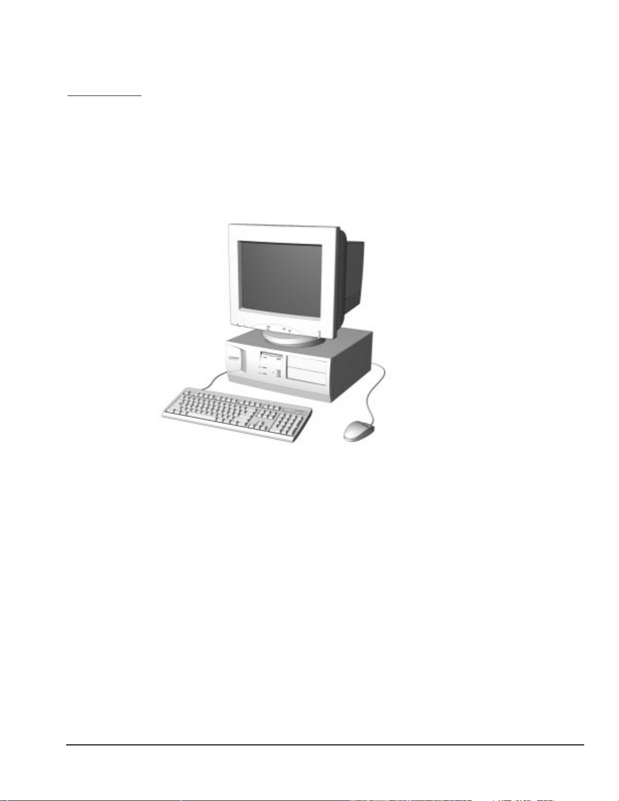
Figure 1-1.
Compaq Deskpro 1000 Series of Personal Computers
Compaq Deskpro 1000 Series of Personal Computers 1-1
Page 10

1.1 Compaq Deskpro 1000 Series of Personal Computer Models
The Compaq Deskpro 1000 Series of Personal Computers is available in desktop configurations
described in the following sections.
Table 1-1
Desktop Models
Configuration
Code Processor Hard Drive Memory
BWF1 P55C/166 1.6 GB 16 MB 256 KB S3 Trio64V2/DX
BWF2 P55C/200 1.6 GB 16 MB 256 KB S3 Trio64V2/DX
✎
All models have maximum expandable memory up to 256 MB.
Internal
Cache Graphics
1-2
Product Description
Page 11

1.2 Features
Item Description
Processor
Speed (MHz)
Cache
L2 (KB), (write-through, direct mapped) 256
Architecture
CMOS RAM, battery backed
Plug and Play capability
Chipset VIA Apollo 590VP
ROM BIOS Flash memory device
Memory
SIMM, 72-pin, non-parity, 66 MHz, EDO
(SIMMs or DIMMs standard but not both)
Base (MB)
Maximum (MB)
SIMM sockets
Memory
DIMM, 168-pin, non-parity, 66 MHz, SDRAM,
(SIMMs or DIMMs standard but not both)
Base (MB)
Maximum (MB)
DIMM sockets
Bays
3.5-inch Internal
3.5-inch External
5.25-inch External
Diskette drive
Standard 3.5-inch drive bay (MB) 1.44
Hard drive
Standard EIDE with drive fault prediction (GB) 1.6
Expansion slots
PCI/ISA/combination 3/3/1
Graphics
S3 Trio64V2/DX Enhanced 64-bit
Graphics (MB)
I/O ports
Standard Serial (2)
Table 1-2
Features
Intel Pentium Processor with MMX Technology
166
200
PCI/ISA
242-byte
Standard
16
256
4
16
256
2
2
1
2
1
Parallel
USB (2)
Monitor
Keyboard
Mouse
continued
Compaq Deskpro 1000 Series of Personal Computers 1-3
Page 12

Table 1-2
Item Description
Power supply 200 watt, 115 VAC, 6.0 A/230 VAC, 3.0 A
Power supply fan Standard
Internal piezo speaker Standard
Internal battery Standard
Operating System Windows 95
Two-button mouse Standard
Compaq Enhanced keyboard
with MS Windows-specific keys Standard
continued
1.3 System Design
This section presents a design overview and functional descriptions of the key components of the
Compaq Deskpro 1000 Series of Personal Computers. All replaceable components are identified
in Chapter 3, and removal/replacement instructions are presented in Chapter 5.
1.3.1 Design Overview
The desktop models of the Compaq Deskpro Series of Personal Computers use a conventional
ATX chassis to house the removable system board, expansion boards, power supply, and mass
storage devices.
All internal components are accessible when the cover—held in place by three screws—is
removed. The front bezel is a separate assembly and is attached to the chassis with release latches.
The system board is easily removed from the chassis after the cover is removed. Details of the
disassembly procedure are found in Chapter 5, “Removal and Replacement Procedures.”
A removable 3.5-inch drive cage is located to the left center of the chassis. This drive cage can be
pulled out from the top, after removing the two screws securing it to the chassis, to provide access
to cable connections and to the screws securing the drives to the drive cage. The removable drive
cage accommodates one external diskette drive and two internal hard drives. The fixed 5.25-inch
drive cage is located to the right of the removable cage and holds a maximum of two drives.
Both the removable and the fixed drive cages allow drive installation without the use of rails. Four
screws secure a drive to the drive cage, and ensure proper alignment of the drive within the cage.
Expansion boards are installed vertically into the system board. A single screw secures each
expansion board to the chassis.
The power supply is mounted in the right rear corner of the chassis. The power supply is held in
place by four screws that are installed through the rear panel of the chassis and a single retaining
screw on the inside on the chassis.
1-4 Product Description
Page 13
1.4 Preloaded Software
This computer is shipped with Windows 95 installed as the operating system.
The following software is preloaded on the computer:
Compaq Online Safety & Comfort Guide
Microsoft Windows 95
1.5 Computer Features
1.5.1 Front Panel Controls and LEDs
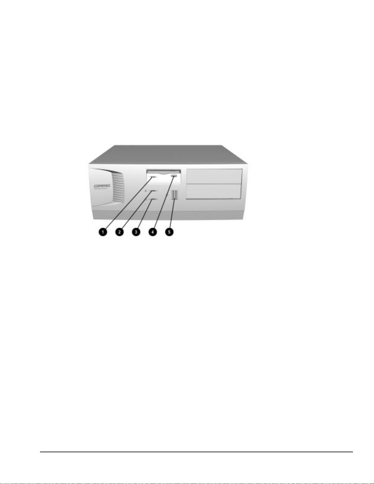
Figure 1-2.
Diskette Drive Activity Light Turns on when the diskette drive is reading or writing.
1
Power-On Light Turns on when the computer is turned on.
2
Hard Drive Activity Light Turns on when the hard drive is reading or writing.
3
Diskette Eject Button Ejects a loaded diskette.
4
Power Button Turns the computer on and off.
5
Front Panel Controls and LEDs
When the hard drive light 3 or diskette drive light 1 is on, the drive is either reading information
from the disk or storing information on the disk.
Compaq Deskpro 1000 Series of Personal Computers 1-5
Page 14
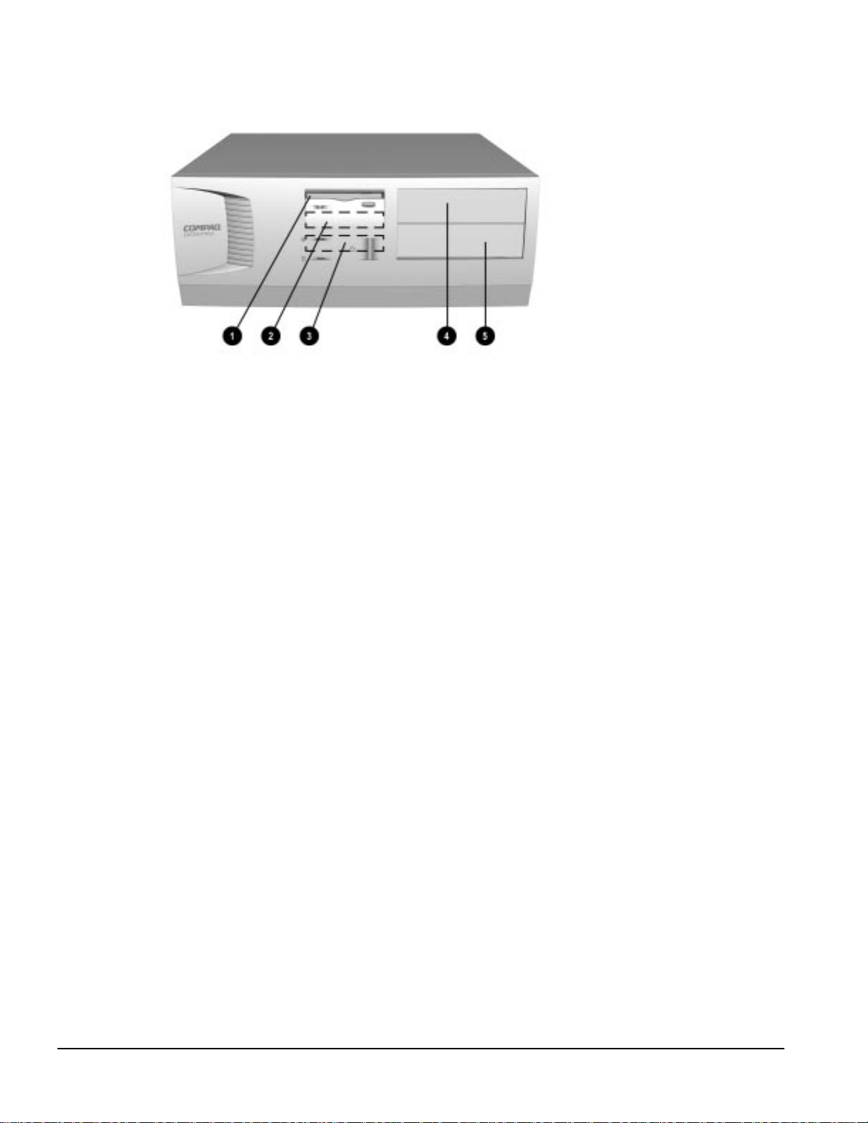
1.5.2 Drive Positions
Figure1-3.
One 3.5-inch 1.44-MB diskette drive
1
One 3.5-inch third-height drive bay for optional drive
2
One 3.5-inch third-height drive bay for primary hard drive
3
One 5.25-inch half-height drive bay for optional drive
4
One 5.25-inch half-height drive bay for optional drive
5
Drive Positions on the Compaq Deskpro 1000 Desktop Computer
1-6 Product Description
Page 15
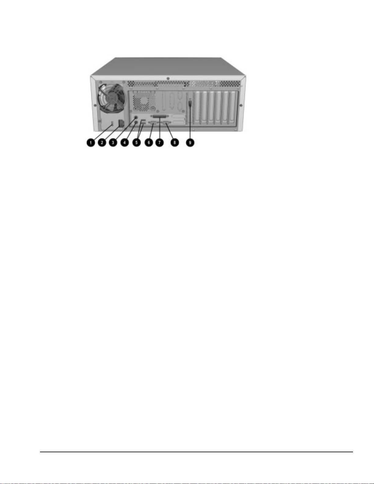
1.5.3 Rear Panel Connectors
Figure 1-4.
Voltage Select Switch (115 V U.S. or 230 V to match geographical requirements)
1
Power Cord Connection
2
Mouse Connector
3
Keyboard Connector
4
Universal Serial Bus (USB) Connectors
5
Serial Connector
6
Parallel Port Connector
7
Serial Connector
8
Monitor Connector
9
Rear Panel Connectors
Compaq Deskpro 1000 Series of Personal Computers 1-7
Page 16
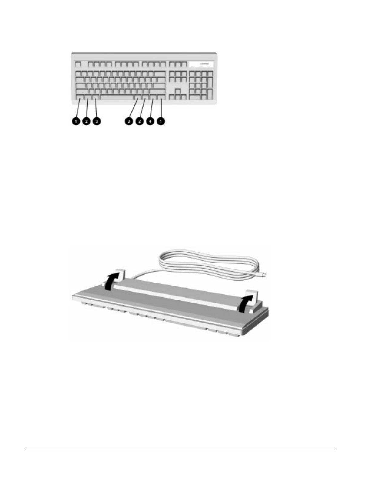
1.6 Enhanced Keyboard
Figure 1-5.
Ctrl Used in combination with another key. Its effect depends on the
1
Windows Logo Keys Opens the Windows Start menu. Used in combination with another
2
Alt Used in combination with another key. Its effect depends on the
3
Windows Application Key Used (like the right mouse button) to open pop-up menus in a
4
Enhanced Keyboard
software application you are using.
key. Its effect depends on the software application you are using.
software application you are using.
Microsoft Office application. May perform other functions in other
software applications.
The keyboard has feet on the bottom that enable the user to tilt the keyboard to a more
comfortable typing angle.
Figure 1-6.
1-8 Product Description
Keyboard Tilt Feet
Page 17

chapter
2
T
ROUBLESHOOTING
This chapter provides troubleshooting information for the Compaq Deskpro 1000 Series of
Personal Computers including:
Power-On Self Test (POST)—POST messages listed in Table 2-1 include a description of
the error, the probable cause, and the recommended action that should be taken to resolve
the error condition.
CMOS Setup Utility—Computer Setup options are available through the CMOS Setup
Utility.
Troubleshooting Without Diagnostics—Tables 2-2 through 2-9 include a
problem/solution checklist for power, diskette drive, display, printer, hard drive, CDROM, and memory.
Adherence to the procedures and precautions described in this chapter is essential for proper
service.
✎
Some features may not be available on all models.
2.1 Power-On Self Test (POST)
The POST procedure is embedded in the system BIOS and performs a series of diagnostic tests
that automatically run when the system is turned on. POST checks the following assemblies to
ensure that the computer system is functioning properly:
Keyboard
Mouse
System board
Memory modules
Video
Diskette drives
Hard drives
Power supply
Controllers
If POST detects an error in the system, an error condition is indicated by an audible and/or visual
message. Table 2-1 explains the error codes and suggests a recommended course of action.
2.1.1 POST Error Messages
An error message may be followed by a prompt to press F1 to continue or press DEL to enter
Setup.
Compaq Deskpro 1000 Series of Personal Computers 2-1
Page 18

Table 2-1
Power-On Self-Test Messages
Message Probable Cause Recommended Action
The computer
beeps:
the beep consists of
continuous long
beeps
The computer
beeps:
the beep consists of
one long beep
followed by two short
beeps
BIOS ROM
Checksum Error System Halted
CMOS Battery
Failed
CMOS Checksum
Error - Defaults
Loaded
CPU at nnnn Displays the running speed of
Display Switch Is Set
Incorrectly
Press Esc to Skip
Memory Test
Floppy Disk(s) Fail Cannot find or initialize the
Hard Disk Install
Failure
No system memory is present. Add system memory.
A video error has occurred
and the BIOS cannot initialize
the video screen to display
any additional information.
The checksum of the BIOS
code in the BIOS chip is
incorrect, indicating the BIOS
code may have become
corrupt.
CMOS battery is no longer
functional.
The checksum of CMOS is
incorrect, so the system loads
the default equipment
configuration.
the CPU.
The display switch on the
system board can be set to
either monochrome or color.
This message indicates the
switch is set to a different
setting than indicated in
Setup.
The system is testing memory. The user may press Esc to skip the full memory
floppy drive controller or the
drive.
Cannot find or initialize the
hard drive controller or the
drive.
Ensure the VGA card is installed correctly and that
the monitor cable is well connected.
Replace the BIOS.
Replace the battery.
A checksum error may indicate that CMOS has
become corrupt. This error may have been caused
by a weak battery. Check the battery and replace
if necessary.
None.
Determine which setting is correct, and then either
turn off the system and change the jumper, or
enter Setup and change the Video selection.
test.
Ensure the controller is installed correctly. If no
diskette drives are installed, be sure the Diskette
Drive selection in Setup is set to None.
This will occur only if the BIOS supports low level
format. Current BIOS does not support low-level
format.
Continued
2-2 Troubleshooting
Page 19

Table 2.1
Continued
Message Probable Cause Recommended Action
Hard Disk(s)
Diagnosis Failure
Keyboard Error or
No Keyboard
Present
Keyboard is Locked
Out - Unlock the
Key
Memory Test This message displays during
Memory Test Fail If POST detects an error
Primary Master Hard
Disk Fail
Primary Slave Hard
Disk Fail
Secondary Master
Hard Disk Fail
Secondary Slave
Hard Disk Fail
The system has run specific
disk diagnostic routines. This
message appears if one or
more hard disks return an
error when the diagnostics
run.
Cannot initialize the keyboard. Ensure the keyboard is attached correctly and no
This message usually
indicates that one or more
keys have been pressed
during the keyboard tests.
a full memory test, counting
down the memory areas being
tested.
during memory testing,
additional information appears
giving specifics about the type
and location of the memory
error.
POST detects an error in the
primary master IDE hard drive.
POST detects an error in the
primary slave IDE hard drive.
POST detects an error in the
secondary master IDE hard
drive.
POST detects an error in the
secondary slave IDE hard
drive.
Hard disk may be damaged, and may need to be
replaced.
keys are pressed during POST. To purposely
configure the system without a keyboard, set the
error halt condition in Setup to Halt on All but
Keyboard. The BIOS then ignores the missing
keyboard during POST.
Ensure no objects are resting on the keyboard.
None.
If this happens often, the memory module may
need to be replaced.
Ensure the controller is installed correctly, the
cable is attached correctly, and the hard disk
jumper is set to primary master. If no hard drive is
installed, be sure the hard drive selection in Setup
is set to None.
Ensure the controller is installed correctly, the
cable is attached correctly, and the hard disk
jumper is set to primary slave. If no hard drive is
installed, be sure the hard drive selection in Setup
is set to None.
Ensure the controller is installed correctly, the
cable is attached correctly, and the hard disk
jumper is set to secondary master. If no hard drive
is installed, be sure the hard drive selection in
Setup is set to None.
Ensure the controller is installed correctly, the
cable is attached correctly, and the hard disk
jumper is set to secondary slave. If no hard drive
is installed, be sure the hard drive selection in
Setup is set to None.
Compaq Deskpro 1000 Series of Personal Computers 2-3
Page 20

2.2 CMOS Setup Utility
The Award BIOS chip contains the ROM setup information of your computer and serves as an
interface between the processor and the rest of the components on the motherboard.
The CMOS Setup Utility, which is built into the BIOS and stored in the CMOS RAM, is executed
when the user changes the battery or the existing settings, or when the system detects an error
during POST and asks you to run the Setup utility. See Chapter 7, “Utilities,” for instructions on
how to use this utility.
✎
To execute the CMOS Setup Utility:
1. Shut down the operating system.
2. Turn the computer off, then on.
3. Press the Delete key when the message “Press DEL to enter Setup” appears on the lower right
4. Use the arrow keys to highlight the setup feature you want to change.
5. Press Enter to open the selected setup feature.
6. Use the arrow keys to highlight the value you want to change.
7. Use the Page Up or Page Down keys to change the selected value.
8. Follow the on-screen instructions to save the changes and exit, or to exit the utility without
✎
The CMOS Setup Utility includes the following options:
Before removing or replacing a subassembly, safeguard the CMOS settings. Write
them down, make a print screen of each CMOS setup page, or use a third-party
CMOS rescue software to store the settings in a file on a write-protected diskette.
hand corner of the screen.
saving any changes.
Failure to configure the system correctly can result in loss of data and reduced
hard drive capacity.
Standard CMOS Setup
BIOS Features Setup
Chipset Features Setup
Power Management Setup
PnP/PCI Configuration Setup
Load BIOS Defaults
Load Setup Defaults
Integrated Peripherals
Supervisor Password
User Password
IDE HDD Auto Detection
Save and Exit Setup
Exit without Saving
2-4 Troubleshooting
Page 21

2.2.1 Preparing the Computer
If you encounter an error condition, complete the following steps before starting problem isolation
procedures:
1. Ensure proper ventilation. The computer should have a 3-inch (7.6-cm) clearance at the back of
the system unit.
2. Turn off the computer and peripheral devices.
CAUTION:
or any other peripheral devices. Disconnecting or connecting any peripheral devices while the unit power
is on can damage the system board.
3. Disconnect any peripheral devices other than the monitor and keyboard. Do not disconnect the
printer if you want to test it or use it to log error messages.
4. Install loop-back and terminating plugs for complete testing.
5. Run a diagnostics utility.
Always ensure that the power is off before disconnecting or reconnecting the mouse, keyboard,
2.2.2 Clearing the Password
If you have to clear the password before changing any of the CMOS settings, refer to Chapter 7,
“Utilities,” for instructions.
2.3 Troubleshooting Without Diagnostics
This section describes some simple, preliminary tests and guidelines for troubleshooting the
computer without using diagnostics software.
✎
Diagnostics software is not included with this computer. Compaq diagnostics
software, Version PC 10.25A, is available at www.compaq.com. Third-party
diagnostics software is also available.
2.3.1 Checklist for Solving Minor Problems
If you encounter some minor problem with the computer or a software application, go through the
following checklist for possible solutions before running any of the diagnostic utilities:
Is the computer connected to a working power outlet?
Is the computer turned on and the power light illuminated?
Are all cables connected properly and seated?
Is the monitor turned on and the power light illuminated?
If the monitor is dim, turn up the brightness and contrast controls of the monitor.
Press and hold any key. If the system beeps, then the keyboard should be operating
correctly.
Are all of the necessary device drivers installed?
Have all printer drivers been installed for each application?
Is the CONFIG.SYS file correct?
Is the AUTOEXEC.BAT file (MS-DOS) or STARTUP.CMD file (OS/2) correct?
Compaq Deskpro 1000 Series of Personal Computers 2-5
Page 22

Was a nonbootable diskette loaded in the diskette drive at power-up?
Are all switch settings correct?
Have all jumper settings been set as instructed by the configuration utility?
Was Computer Setup run after installing options (memory, disk drives, expansion
boards, etc.) and before installing industry standard architecture (ISA) boards?
2.3.2 Power Problems
This section identifies some quick checks for power-related problems.
Problem Possible Solution
Computer will not turn on. Ensure that the computer is connected to a power source.
Computer does not automatically
display the date and time.
(Date/Time not set)
Computer powered off
automatically.
Table 2-2
Solutions for Power Problems
Cables to the external power source may be unplugged. Ensure that
cables connecting the computer and the external source are plugged
in properly.
A PCI or ISA card that has been installed may be defective. Remove
any adapter card that was just installed.
The real-time clock (RTC) battery may need to be replaced. See
Chapter 5 for replacement procedures.
The unit temperature may have been exceeded. Check the fan for
function and blockage.
Check to ensure that the power cord is securely plugged into the wall
and the unit.
2-6 Troubleshooting
Page 23

2.3.3 Diskette Drive Problems
This section identifies some quick checks for diskette drive–related problems.
Solutions for Diskette Drive Problems
Problem Possible Solution
Diskette drive light stays on. 1. Diskette may be damaged. In Windows 95, run SCANDISK. At the
Diskette drive cannot write to
a diskette.
Diskette drive cannot read a
diskette.
A problem has occurred with a
disk transaction
Nonsystem disk message. Remove the diskette from the drive and press any key.
Drive not found. Check the cables for loose connections.
Table 2-3
Start menu, highlight Programs, select Accessories, select System
Tools, then SCANDISK.
2. Diskette could be installed incorrectly. Remove the diskette and
reinsert.
3. Software program may be damaged. Replace the program
diskettes.
4. Drive cable is not properly connected. Reconnect drive cable.
1. Diskette is not formatted. Format the diskette.
2. Diskette is write-protected. Either use another diskette that is not
write-protected or disable the write protection on the diskette.
3. Writing to the wrong drive. Check the drive letter in the path
statement.
4. Not enough space is left on the diskette. Use another diskette to
write the information.
5. Diskette write control is disabled. Check the security feature
settings in Setup.
1. Diskette is not formatted. Format the diskette.
2. Using the wrong diskette type for the drive type. Use a diskette that
is compatible with the drive.
3. Reading the wrong drive. Check the drive letter in the path
statement.
4. Diskette drive has been disabled by Computer Setup. Run
Computer Setup and enable the diskette drive.
The directory structure is bad, or there is a problem with a file. In
Windows 95, run SCANDISK. At the Start menu, highlight Programs,
select Accessories, select System Tools, then SCANDISK.
Compaq Deskpro 1000 Series of Personal Computers 2-7
Page 24

2.3.4 Display Problems
This section identifies some quick checks for display-related problems.
Problem Possible Solution
Screen is blank.
Graphics colors are wrong.
Characters are dim.
Monitor does not function properly
when used with the energy saver
features.
Blurry display or requested
resolution cannot be set.
The picture is broken up; it rolls,
jitters, or blinks.
Garbled characters on the screen
are mixed with text.
Screen goes blank.
Monitor overheats.
Cursor will not move using the
arrow keys on the numeric keypad.
Table 2-4
Solutions for Display Problems
1. Monitor is not turned on and the monitor light is not on. Turn on the
monitor and check that the monitor light is on.
2. Screen save has been initiated. Press any key or move the mouse
to light the screen.
3. Check the cable connection from the monitor to the computer and
check the electrical outlet.
4. The brightness need adjusting. Adjust the brightness control.
5. The energy saver feature has been enabled. Hit any key or type
the password.
6. The RGB (Red, Green, Blue) input switch on the back of the
monitor is incorrectly set. Set the monitor's input switch to 75 ohms
and, if there is a sync switch, set it to External.
7. If a fixed-sync monitor is used, be sure that the monitor can accept
the same sweep rate as the resolution chosen.
1. Ensure that the Red, Green, and Blue BNC cables are connected
to the corresponding monitor connectors.
2. Be sure the monitor's RGB inputs are set to 75 ohms.
1. Adjust the monitor's brightness and contrast controls.
2. Check that the video cable is securely connected to the graphics
card and monitor.
3. Set the RGB switch (and sync options, if available) to 75 ohms,
with the sync set to External. Refer to the documentation included
with the monitor.
Monitor without the energy saver feature is being used with energy
saver features enabled. Disable the monitor energy saver feature.
If the graphics controller was upgraded, the correct display drivers
may not be loaded. Install the correct display drivers on the diskette
included in the upgrade kit.
1. Be sure the monitor cable is securely connected to the computer.
2. In a 2-monitor system or if another monitor is in close proximity, be
sure the monitors are not interfering with each other's magnetic
field by moving them apart.
The ANSI.SYS driver is not in the
ANSI.SYS driver to the
DEVICE = C:\CPQDOS\ANSI.SYS
A screen blanking utility may be installed or energy saver features are
enabled. Press any key or type password.
There is not enough ventilation space for proper airflow. Leave at
least 3 inches (7.6-cm) of ventilation space. Also, be sure there is
nothing on top of the monitor to obstruct air flow.
The Num Lock key is on. Press the Num Lock key. The Num Lock
light should not be on when you want to use the arrow keys.
CONFIG.SYS
CONFIG.SYS
file by adding the following line:
file. Add the
2-8 Troubleshooting
Page 25

2.3.5 Printer Problems
This section identifies some quick checks for printer-related problems.
Problem Possible Solution
Printer will not print. 1. Printer is not turned on and online. Turn the printer on and make
Printer will not turn on. The cables may not be connected properly. Reconnect all cables and
Prints garbled information. 1. The correct printer drivers for the application are not installed.
Printer is offline. The printer may be out of paper. Check the paper tray and refill it if it
Table 2-5
Solutions for Printer Problems
sure it is online.
2. The correct printer drivers for the application are not installed.
Install the correct printer drivers for the application.
3. If the computer is on a network, you may not have made the
connection to the printer. Make the proper network connections to
the printer.
check the power cord and electrical outlet.
Install the correct printer drivers for the application.
2. The cables may not be connected properly. Reconnect all cables.
is empty. Select online.
Compaq Deskpro 1000 Series of Personal Computers 2-9
Page 26

2.3.6 Hard Drive Problems
This section identifies some quick checks for hard drive–related problems.
Problem Possible Solution
Hard drive error occurs. Hard disk has bad sectors or has failed. Use a utility to locate and
Disk transaction problem. Either the directory structure is bad or there is a problem with a file. At
Drive not found. 1. Cable could be loose. Check cable connections.
Nonsystem disk message. 1. The system is trying to start from a diskette that is not bootable.
Hard drive operation seems slow. The hard disk files may be fragmented.
Table 2-6
Solutions for Hard Drive Problems
block usage of bad sectors. If necessary, reformat the hard disk.
the C:\> prompt, run SCANDISK to check for problems. If problems
exist, run SCANDISK /AUTOFIX to correct the problems.
2. The system may not have automatically recognized a newly
installed device. If Windows 3.1 is installed, run Computer Setup
and identify the new device. If Windows 95 is installed, run Device
Manager and identify the device.
3. If the drive is a secondary drive that has just been installed on the
same controller as the primary drive, verify that the jumpers for
both drives are set correctly.
Remove the diskette from the diskette drive.
2. The system is trying to start from the hard drive but the hard disk
has been damaged. Insert a bootable diskette into the diskette
drive and restart the computer with Ctrl+Alt+Del.
3. Diskette boot has been disabled in Computer Setup. Run
Computer Setup and enable diskette boot.
At the C:\> prompt, run SCANDISK to check for problems. If problems
exist, run SCANDISK /F to correct the problems. If a large number of
lost allocation units is found, run the MS-DOS defragmentation
program DEFRAG. See the Microsoft Windows & MS-DOS 6.2 User's
Guide for more information.
Alternatively, at the C:\> prompt, run SCANDISK to check for
problems. If problems exist, run SCANDISK /AUTOFIX to correct the
problems. If a large number of lost allocation units is found, run the
MS-DOS defragmentation program DEFRAG. Type HELP SCANDISK
for more information.
2-10 Troubleshooting
Page 27

2.3.7 Hardware Installation Problems
This section identifies some quick checks for hardware problems.
Solutions for Hardware Installation Problems
Problem Possible Solutions
A new device is not recognized as
part of the computer system.
The computer supports Plug and
Play, but the hardware
configuration settings in Computer
Setup do not match the settings in
Windows 95 Device Manager.
1. The Computer Setup utility has not been run to configure the new
device. Run the Computer Setup utility.
2. When the system advised you of changes to the configuration, you
did not accept them. Reboot the computer and follow the
instructions for accepting the changes.
3. The system may not have automatically recognized the new device.
If Windows 3.1 is installed, run Computer Setup and identify the
new device. If Windows 95 is installed, run Device Manager and
identify the device.
4. A Plug and Play board may not automatically configure when added
if the default configuration conflicts with other devices. Run
Computer Setup (Windows 3.1 installed) or run Device Manager
(Windows 95 installed) to deselect the automatic settings for the
board and choose a basic configuration that doesn’t cause a
resource conflict.
5. The cables for the new external device are loose or the power
cables are unplugged. Check all cables.
6. The power switch for the new external device is not turned on. Turn
off the computer, turn on the external device, and then turn the
computer on to integrate the new device with the computer.
7. If the drive is a secondary drive that has just been installed on the
same controller as the primary drive, verify that the jumpers for both
drives are set correctly.
In Windows 95, onboard serial devices that are assigned to ports other
than COM1 or COM2, have their configuration saved statically in
CMOS. When the system is rebooted, the ROM configures the device
to the static setting; when Windows 95 loads, it configures the device
to the configuration set via Device Manager. In such cases, the
configuration shown when CMOS Setup is run does not match what
was set up via Device Manager.
If these devices must be configured a certain way before Windows 95
loads, then the serial port devices on the system should only be
configured to COM1 or COM2 resources. If the system has two serial
devices plus a modem, then the first serial device can be COM1 or
COM2 or disabled, the modem can be COM1 or COM2 or disabled,
and the second serial device can be COM4 or disabled.
Table 2-7
Compaq Deskpro 1000 Series of Personal Computers 2-11
Page 28

2.3.8 CD-ROM Drive Problems
This section identifies some quick checks for CD-ROM drive problems.
Problem Possible Solution
Cannot read compact disc. 1. CD is not properly seated in the drive. Eject the CD, correctly seat
System will not boot from CD-ROM
drive.
Cannot eject compact disc (trayload unit only).
CD-ROM device is not detected;
driver is not loaded.
Table 2-8
CD-ROM Drive Problems
it in the drive, then reload.
2. CD has been loaded upside down. Eject the CD, turn it over, then
reload.
1. The CD-ROM boot is not enabled through the CMOS Setup utility.
Run the CMOS Setup utility and set the drive priorities.
2. Ensure that drive cabling and jumpers are set correctly. To boot a
SCSI drive, the drive ID number must be set to 0.
CD is not properly seated in the drive. Turn off the computer and
insert a thin metal rod into the emergency eject hole and push firmly
(a straightened paper clip can be used). Slowly pull the tray out from
the drive until the tray is fully extended, then remove the CD.
CD-ROM drive is not connected properly. Open the computer and
check to see that the drive cable is connected properly and the drive
jumpers are set correctly.
✎
Some features may not be available on all models.
2.3.9 Memory Problems
This section identifies some quick checks for memory-related problems.
Problem Possible Solution
Out of Memory error. 1. In Windows 95, use the Device Manager to check memory
Memory count during POST is
wrong.
Insufficient memory error during
operation
Table 2-9
Memory Problems
configuration.
2. The computer has run out of memory to run the application. Check
the application documentation to determine the memory
requirements.
The memory modules may not be installed correctly. Check that the
memory modules have been installed correctly and that mixed EDO
and FPM DRAM are in the correct bank, then run the Configuration
utility. (If the system contains mixed EDO and FPM DRAMs, the EDO
pair is one bank and the FPM pair is another bank.)
1. Too many Terminate and Stay Resident programs (TSRs) are
installed. Delete any unnecessary TSRs.
2. The computer has run out of memory for the application. Check
the memory requirements for the application or add more memory
to the computer.
2-12 Troubleshooting
Page 29
chapter
3
I
LLUSTRATED PARTS CATALOG
This chapter provides an illustrated parts breakdown and a reference for spare parts for the
Compaq Deskpro 1000 Series of Personal Computers.
Figure 3-1.
Compaq Deskpro 1000 Series of Personal Computers
Compaq Deskpro 1000 Series of Personal Computers 3-1
Page 30
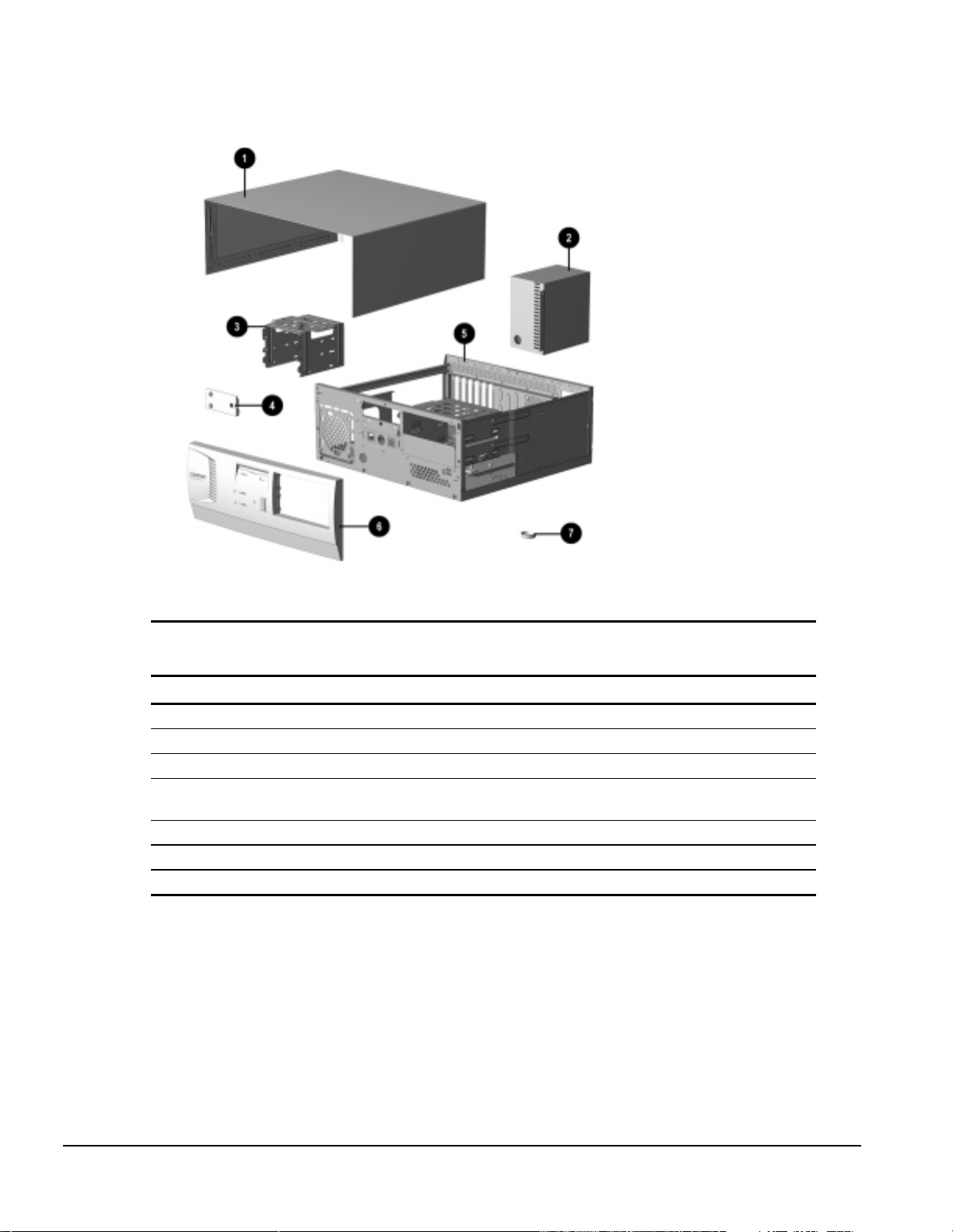
3.1 System Unit
Figure 3-2.
System Unit
Table 3-1
System Unit Spare Parts
Description Spare Part Number Warranty Tier
System unit cover 333833-001 A
1
Power supply, 200W (Includes fan) 333818-001 A
2
Drive Cage 333838-001 A
3
LED holder (reference only; part of Miscellaneous Plastics
4
kit)
Base pan (chassis assembly) 333834-001 A
5
Front bezel. (Includes power switch cap and bezel blanks) 333839-001 A
6
Feet (reference only; part of Miscellaneous Plastics kit)
7
3-2 Illustrated Parts Catalog
Page 31

3.2 Mass Storage Devices
Figure 3-3.
Mass Storage Devices
Table 3-2
Mass Storage Devices
Description Spare Part Number Warranty Tier
3.5-inch, 1.44-MB, diskette drive 333817-001 A
1
1.6-GB hard drive 333816-001 A
2
Compaq Deskpro 1000 Series of Personal Computers 3-3
Page 32

3.3 Cables
Figure 3-4.
Cables
Table 3-3
Cables
Description Spare Part Number Warranty Tier
Miscellaneous cable kit includes: 333824-001 A
Cable, diskette drive
1
Cable, hard drive
2
Cables, LED: hard drive and power
3
Cable, power, APD 121259-001 A
4
Cable, power, EMEA* 285810-001 A
4
Cable, power, ANZ* 285811-001 A
4
Cable, power, LA, Thailand, Taiwan* 142766-001 A
4
Cable, power, PRC* 298594-AA1 A
4
*Not shown
3-4 Illustrated Parts Catalog
Page 33

3.4 Standard and Optional Boards
Figure 3-5. Standard and Optional Boards
Table 3-4
Standard and Optional Boards
Description Spare Part Number Warranty Tier
System board, P55C 333814-001 A
1
EDO SIMM, 8 MB 285734-001 A
2
SDRAM DIMM, 16 MB 333820-001 A
3
. Video upgrade memory, 512 KB 333822-001 A
4
Video board* 333821-001 A
5
Microprocessor, P55C/200 MHz, with thermal pad 240181-002 A
6
Microprocessor, P55C/166 MHz, with thermal pad* 240181-001 A
6
*Not shown
✎
Video board design varies by model.
Compaq Deskpro 1000 Series of Personal Computers 3-5
Page 34

3.5 Keyboards
Figure 3-6.
Keyboard
Table 3-5
Keyboards
Description Spare Part Number Warranty Tier
1. Arabic* 333828-171 A
2. BHCSY (Bosnia-Herzegovina, Croatia, Slovenia, and
Yugoslavia)*
3. Brazilian Portuguese* 333828-201 A
4. Czech* 333828-221 A
5. French* 333828-051 A
6. Hungarian* 333828-211 A
7. International 333828-B31 A
8. Korean (Hanguel)* 333828-AD1 A
9. LA Spanish* 333828-161 A
10. Russian* 333828-251 A
11. Slovakian* 333828-231 A
12. Taiwanese* 333828-AB1 A
13. Thai* 333828-281 A
14. Turkish* 333828-141 A
* Not shown
333828-B41 A
3-6 Illustrated Parts Catalog
Page 35

3.6 Miscellaneous Hardware Kit
Figure 3-7.
Miscellaneous Hardware Kit
Table 3-6
Miscellaneous Hardware Kit
Description Spare Part Number Warranty Tier
Miscellaneous hardware kit. Includes: 333832-001 D
Slot Cover (2 each)
1
I/O Panel
2
M3x0.5P-5mm screws (25 each)*
3
#6-32UNC ¼-inch hex screws (25 each)*
4
Hex screw locks (25 each)*
5
* Not shown
Compaq Deskpro 1000 Series of Personal Computers 3-7
Page 36

3.7 Miscellaneous Plastics Kit
Figure 3-8.
Miscellaneous Plastics Kit
Table 3-7
Miscellaneous Plastics Kit
Description Spare Part Number Warranty Tier
Miscellaneous plastics kit, includes:
LED Holder
1
Card guide
2
System board standoff (2 each)
3
Cable twist
4
Bezel blank, 5.25-inch
5
Feet (4 each)
6
* Not shown
333831-001 D
3-8 Illustrated Parts Catalog
Page 37

3.8 Miscellaneous Parts
Figure 3-9.
Description Spare Part Number Warranty Tier
Two-button mouse 298792-001 A
1
Battery, real-time clock (external) 234556-001 A
2
Active heat sink (P55C/200 with thermal pad and
3
captive clip; replaces passive heat sink)
Power switch (with spring, LED holder, and cable) 333827-001 A
4
Miscellaneous Parts
3.9 Shipping Boxes
Description Spare Part Number Warranty Tier
Shipping box, with buns (return kit)
3.10 Documentation
Table 3-8
Miscellaneous Parts
333825-001 A
Table 3-9
Shipping Boxes
333840-001 D
Table 3-10
Documentation
Description Spare Part Number Warranty Tier
Maintenance & Service Guide 333835-001 D
Illustrated Parts Map 333836-001 D
Reference Guide 333837-001 D
Compaq Deskpro 1000 Series of Personal Computers 3-9
Page 38

chapter
4
R
EMOVAL AND REPLACEMENT PRELIMINARIES
This chapter provides general service information for the computer. Adherence to the procedures
and precautions described in this chapter is essential for proper service.
4.1 Electrostatic Discharge Information
A sudden discharge of static electricity from your finger or other conductor can destroy staticsensitive devices or microcircuitry. Often the spark is neither felt nor heard, but damage occurs.
An electronic device exposed to electrostatic discharge (ESD) may not be affected at all and can
work perfectly throughout a normal cycle. Or it may function normally for a while, then degrade
in the internal layers, reducing its life expectancy.
Networks built into many integrated circuits provide some protection, but in many cases, the
discharge contains enough power to alter device parameters or melt silicon junctions.
4.1.1 Generating Static
Table 4-1 shows how different activities generate static electricity at different electrostatic voltage
levels.
Table 4-1
Typical Electrostatic Voltages
Relative Humidity
Event 10% 40% 55%
Walking across carpet 35,000 V 15,000 V 7,500 V
Walking across vinyl floor 12,000 V 5,000 V 3,000 V
Motions of bench worker 6,000 V 800 V 400 V
Removing DIPs* from plastic tube 2,000 V 700 V 400 V
Removing DIPs* from vinyl tray 11,500 V 4,000 V 2,000 V
Removing DIPs* from Styrofoam 14,500 V 5,000 V 3,500 V
Removing bubble pack from PCB 26,500 V 20,000 V 7,000 V
Packing PCBs in foam-lined box 21,000 V 11,000 V 5,000 V
*Dual Inline Packaging (DIP) is the packaging around individual microcircuitry. These are then multi-
packaged inside plastic tubes, trays, or Styrofoam.
700 volts can degrade a product.
✎
Compaq Deskpro 1000 Series of Personal Computers 4-1
Page 39

4.1.2 Preventing Electrostatic Damage to Equipment
Many electronic components are sensitive to ESD. Circuitry design and structure determine the
degree of sensitivity. The following proper packaging and grounding precautions are necessary to
prevent damage to electric components and accessories.
To avoid hand contact, transport products in static-safe containers such as tubes, bags, or
boxes.
Protect all electrostatic parts and assemblies with conductive or approved containers or
packaging.
Keep electrostatic sensitive parts in their containers until they arrive at static-free stations.
Place items on a grounded surface before removing them from their container.
Always be properly grounded when touching a sensitive component or assembly.
Avoid contact with pins, leads, or circuitry.
Place reusable electrostatic-sensitive parts from assemblies in protective packaging or
conductive foam.
4.1.3 Personal Grounding Methods
The method for grounding must include either a wrist strap or a foot strap at a grounded
workstation. When seated, wear a wrist strap connected to a grounded system. When standing, use
footstraps and a grounded floor mat.
Table 4-2
Static Shielding Protection Levels
Method Voltage
Antistatic plastic 1,500
Carbon-loaded plastic 7,500
Metallized laminate 15,000
4-2 Removal and Replacement Preliminaries
Page 40

4.1.4 Grounding Workstations
To prevent static damage at the workstation, use the following precautions:
Cover the workstation with approved static-dissipative material. Provide a wrist strap
connected to the work surface and properly grounded tools and equipment.
Use static-dissipative mats, foot straps, or air ionizers to give added protection.
Handle electrostatic sensitive components, parts, and assemblies by the case or PCB
laminate. Handle them only at static-free workstations.
Turn off power and input signals before inserting and removing connectors or test
equipment.
Use fixtures made of static-safe materials when fixtures must directly contact dissipative
surfaces.
Keep work area free of nonconductive materials such as ordinary plastic assembly aids and
Styrofoam.
Use field service tools, such as cutters, screwdrivers, and vacuums, that are conductive.
Use a portable field service kit with a static-dissipative vinyl pouch that folds out on a
work mat. Also, use a wrist strap and a ground cord for the work surface. Ground the cord
to the chassis of the equipment undergoing test or repair.
4.1.5 Personal Grounding Equipment
Use the following equipment to prevent static electricity damage to equipment:
Wrist Straps are flexible straps with a minimum of one-megohm +/- 10% resistance in the
ground cords. To provide proper ground, a strap must be worn snug against bare skin. The ground
cord must be connected and fit snugly into the banana plug connector on the grounding mat or
workstation.
Heelstraps/Toestraps/Bootstraps can be used at standing workstations and are compatible with
most types of shoes or boots. On conductive floors or dissipative floor mats, use them on both feet
with a minimum of one-megohm resistance between the operator and ground. To be effective, the
conductive strips must be worn in contact with the skin.
Compaq Deskpro 1000 Series of Personal Computers 4-3
Page 41

4.1.6 Recommended Materials and Equipment
Other materials and equipment that are recommended for use in preventing static electricity
include:
Antistatic tape
Antistatic smocks, aprons, or sleeve protectors
Conductive bins and other assembly or soldering aids
Conductive foam
Conductive tabletop workstations with ground cord of one-megohm resistance
Static-dissipative table or floor mats with hard tie to ground
Field service kits
Static awareness labels
Wrist straps and footwear straps providing one-megohm +/- 10% resistance
Material handling packages
Conductive plastic bags
Conductive plastic tubes
Conductive tote boxes
Opaque shielding bags
Transparent metallized shielding bags
Transparent shielding tubes
4.2 Service Considerations
Listed below are some of the considerations that you should keep in mind during the disassembly
and assembly of the computer.
4.2.1 Tools and Software Requirements
To service the computer, you need the following:
Phillips-head screwdrivers for use with #0 and #1 screws
Flat-bladed screwdriver
Diagnostics software
✎
Diagnostics software is not included with this computer. Compaq diagnostics
software, Version PC 10.25A, is available from the Compaq world-wide web site
at www.compaq.com. Third-party diagnostics software is also available.
4-4 Removal and Replacement Preliminaries
Page 42

4.2.2 Screws
The screws used in the computer are not interchangeable. They may have standard or metric
threads and may be of different lengths. If an incorrect screw is used during the reassembly
process, it can damage the unit. Compaq strongly recommends that all screws removed during
disassembly be kept with the part that was removed, then returned to their proper locations.
✎
As each subassembly is removed from the computer, it should be placed away
from the work area to prevent damage.
4.2.3 Cables and Connectors
Most cables used throughout the unit are flat, flexible cables. These cables must be handled with
extreme care to avoid damage. Apply only the tension required to seat or unseat the cables during
insertion or removal from the connector. Handle cables by the connector whenever possible. In all
cases, avoid bending, twisting, or tearing the cables, and ensure that the cables are routed in such a
way that they cannot be caught or snagged by parts being removed or replaced.
CAUTION:
reassembly process. Improper cable placement can damage the computer.
When servicing this computer, ensure that cables are placed in their proper location during the
4.2.4 Hard Drives
Handle hard drives as delicate precision components, avoiding all physical shock and vibration.
This applies to failed drives as well as spares.
Use only the packaging provided by Compaq for shipping.
Do not remove hard drives from the shipping package for storage.
Keep hard drives in their protective packaging until they are actually mounted in the CPU
or external storage unit.
Avoid dropping drives from any height onto any surface.
4.2.5 Plastic Parts
Plastic parts can be damaged by the use of excessive force during disassembly and reassembly.
When handling the plastic parts, use care. Do not use a screwdriver or similar tool to pry apart the
plastic components.
4.2.6 Lithium Battery
The battery that came with the computer is replaceable.
CAUTION:
attempt, thereby making it unusable. Do not abuse or disassemble the lithium battery, as it may explode if
mistreated.
Never attempt to remove a lithium battery. You can damage the system board in such an
Compaq Deskpro 1000 Series of Personal Computers 4-5
Page 43

chapter
5
R
EMOVAL AND REPLACEMENT PROCEDURES
This chapter provides subassembly/module level removal and replacement procedures for the
Compaq Deskpro 1000 Series of Personal Computers.
Before removing or replacing a subassembly, safeguard the CMOS settings, by writing them
down, making a print screen of each CMOS setup page, or using a third-party CMOS rescue
software to store the settings in a file on a write-protected diskette.
✎
After completing all necessary removal and replacement procedures, run the CMOS Setup Utility
to reconfigure the computer. See Chapter 7, “Utilities,” for instructions on how to run the CMOS
Setup Utility.
To facilitate reassembly of any part of the computer, note the orientation of each
cable connector and the routing of each cable before you disconnect it.
5.1 Serial Number
The computer serial number should be provided to Compaq whenever requesting information or
ordering spare parts. The serial number is located on the system cover at the right front corner, 1
and also on the rear of the chassis to the left of and above the expansion slot area.
Figure 5-1.
Locating the Serial Number
Compaq Deskpro 1000 Series of Personal Computers 5-1
Page 44
5.2 Disassembly/Assembly Sequence
5.3 Computer Feet
5.4 Preparation for Disassembly
5.5 System Unit Cover
5.6 Expansion Board
5.7 Expansion Board Guide
5.8 System Board
5.9 Graphics Memory
5.10.1 SIMM Module
5.10.2 DIMM Module
5.11 Power Supply
5.12 Microprocessor
5.13 Front Bezel
5.14 LED Retainer Assembly
5.15 LED Cables
5.16 Power Button
5.17 Bezel Blank
5.18 Battery
5.19.2 Drive Cage
5.19.3 3.5-Inch Drive
5.19.4 5.25-Inch Drive
5-2 Removal and Replacement Procedures
Page 45

5.3 Feet
Four rubber feet are mounted to the underside of the base pan. No parts have to be removed to
access the feet. The replacement feet have an adhesive surface and are shipped with a protective
strip in place.
Remove the feet and clean the metal with a clean, dry cloth. Remove the protective strip from the
replacement feet before installation.
Figure 5-2.
Installing the Feet
5.4 Preparation for Disassembly
1. Remove any diskette, compact disc or tape from the computer.
2. Turn off the computer and any peripheral devices connected to it.
CAUTION:
3. Disconnect the power cord from the electrical outlet and then from the computer.
4. Disconnect all peripheral devices from the computer.
✎
During disassembly, label each cable as you remove it, noting its position and
routing.
The computer power switch should be turned off before you disconnect any cables.
Compaq Deskpro 1000 Series of Personal Computers 5-3
Page 46

5.5 System Unit Cover
1. Perform preparation procedures (Section 5.4).
2. Remove the three screws on the rear of the computer to release the cover.
3. Slide the computer cover backward about 1 inch (2.5 cm).
4. Lift the cover up, then off the unit.
Figure 5-3.
Removing the System Unit Cover
To replace the cover, reverse the previous procedure.
5.6 Expansion Board
The Compaq Deskpro 1000 Series of Personal Computers contains seven expansion slots:
Three dedicated 32-bit PCI (Peripheral Component Interconnect) expansion slots
1
One PCI/ISA shared expansion slot
2
Three dedicated 32-bit ISA (Industry Standard Architecture) expansion slots
3
Figure 5-4.
5-4 Removal and Replacement Procedures
Location of the Slots
Page 47

1. Perform preparation procedures (Section 5.4).
2. Remove the system unit cover (Section 5.5).
3. Remove the screw securing the expansion board to the chassis.
4. Pull the board out of the slot.
Figure 5-5.
Removing a Board
To replace a board, reverse the previous procedure.
Compaq Deskpro 1000 Series of Personal Computers 5-5
Page 48

5.7 Expansion Board Guide
1. Perform preparation procedures (Section 5.4).
2. Remove the system unit cover (Section 5.5).
3. Remove all expansion boards from the computer (Section 5.6).
4. Press in on the two plastic clips 1 on the right side of the guide. The guide will pop out of the
chassis.
Figure 5-6.
To replace the expansion board guide, reverse the previous procedure.
Removing the Expansion Board Guide
5-6 Removal and Replacement Procedures
Page 49

5.8 System Board
1. Perform preparation procedures (Section 5.4).
2. Remove the system unit cover (Section 5.5).
3. Remove all expansion boards (Section 5.6).
4. Disconnect any cables plugged into the system board.
5. Remove the seven screws securing the system board to the chassis.
6. Pinch the two standoff tabs 1 to release the system board, lifting the board at the same time to
remove it from the standoffs.
7. Pull the board forward about one-half inch, then lift it up and out of the chassis.
Figure 5-7.
To replace the system board, reverse the previous procedure.
Removing the System Board
Compaq Deskpro 1000 Series of Personal Computers 5-7
Page 50

5.9 Graphics Memory
1. Perform preparation procedures (Section 5.4).
2. Remove the system unit cover (Section 5.5).
3. Remove the video graphics board and place on a protected surface (Section 5.6).
4. Install the two 512-KB memory upgrade modules, making sure that the modules are firmly
seated.
✎
To replace the video graphics board, reverse the previous procedure.
Video card design varies by model.
Figure 5-8.
Installing a Graphics Module
5-8 Removal and Replacement Procedures
Page 51

5.10 Memory Modules
You can expand computer memory by installing industry-standard single inline memory modules
(SIMMs) or dual inline memory modules (DIMMs) on the system board.
The system board includes:
Four SIMM sockets that can be populated with Extended Data Output (EDO) or Fast Page
Mode (FPM) modules installed in equally matched pairs; for example, two 8-MB modules,
two 16-MB modules, or two 32-MB modules.
Two DIMM sockets that can be populated with EDO or SDRAM modules either singly or
in pairs.
Figure 5-9.
DIMM 1 (Bank 0)
1
DIMM 2 (Bank 1)
2
SIMM 1 & 2 (Bank 0)
3
SIMM 3 & 4 (Bank 1)
4
✎
The system board can use either SIMM or DIMM memory, but not both at the
same time, and can be populated as shown in the Table 5-2.
Memory Module Sockets on the System Board
Compaq Deskpro 1000 Series of Personal Computers 5-9
Page 52

Table 5-1
Memory Configuration Options
Total System
Memory, MB
8 4 & 4 8
16 4 & 4 4 & 4 8 8
32 8 & 8 8 & 8 16 16
64 16 & 16 16 & 16 32 32
128 32 & 32 32 & 32 64 64
256 64 & 64 64 & 64 128 128
SIMM 3 & 4
(Bank 1)
8 & 8 16
16 & 16 32
32 & 32 64
64 & 64
SIMM 1 & 2
(Bank 0)
DIMM 1
(Bank 0)
DIMM 2
(Bank 1)
5-10 Removal and Replacement Procedures
Page 53
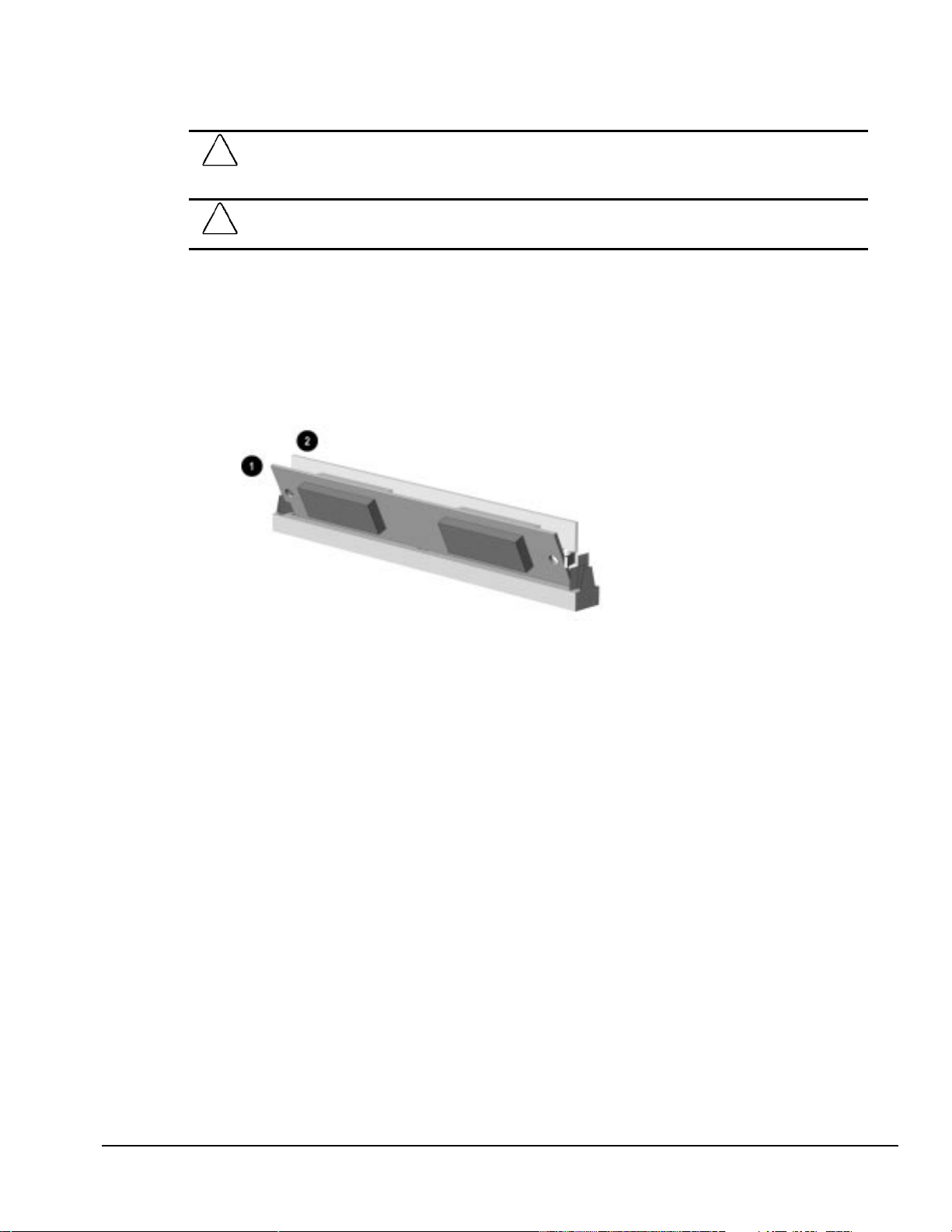
5.10.1 Installing a SIMM Module
CAUTION:
beginning these procedures, ensure that you are discharged of static electricity by briefly touching a
grounded metal object.
CAUTION
damage the module.
1. Perform preparation procedures (Section 5.4).
2. Remove the system unit cover (Section 5.5).
3. Insert a memory module at a 45-degree angle into a SIMM socket on the system board 1.
✎
A memory module can be installed only one way. Match the notch on the module
with the tab on the memory socket. Push the module down into the socket,
ensuring that the module is fully inserted and properly seated.
Static electricity can damage the electronic components or optional equipment. Before
: When handling a memory module, be careful not to touch any of the contacts. Doing so may
Figure 5-10
4. Rotate the module to an upright position, allowing the latches to snap into place 2.
5. Repeat steps 3 and 4 for each module that you want to install.
6. Replace the system unit cover.
7. Plug in the computer power cord.
8. Turn on the computer.
✎
9. Test the system (optional) using a diagnostics software.
✎
The computer recognizes system memory upgrades and automatically reconfigures
the computer. If, for some reason, the memory upgrades do not configure
correctly, run the CMOS Setup Utility to reconfigure the computer. See Chapter 7,
“Utilities,” for information running the CMOS Setup Utility.
Diagnostics software is not included with this computer. Compaq diagnostics
software, Version PC 10.25A, is available from the Compaq world-wide web site
at www.compaq.com. Third-party diagnostics software is also available.
Installing a SIMM Module
Compaq Deskpro 1000 Series of Personal Computers 5-11
Page 54

5.10.2 Installing a DIMM Module
CAUTION:
beginning these procedures, ensure that you are discharged of static electricity by briefly touching a
grounded metal object.
CAUTION:
damage the module.
1. Perform preparation procedures (Section 5.4).
2. Remove the system unit cover (Section 5.5).
3. Press outward at the same time on both latches 1 of the DIMM socket and insert the memory
module 2 into the socket.
✎
4. Push the module down into the socket, ensuring that the module is fully inserted and properly
A memory module can be installed only one way. Match the notch on the module
with the tab on the memory socket.
seated 3.
Static electricity can damage the electronic components or optional equipment. Before
When handling a memory module, be careful not to touch any of the contacts. Doing so may
Figure 5-11.
5. Replace the system unit cover.
6. Plug in the computer power cord.
7. Turn on the computer.
✎
8. Test the system (optional) using a diagnostics software.
✎
5-12 Removal and Replacement Procedures
The computer recognizes system memory upgrades and automatically reconfigures
the computer. If, for some reason, the memory upgrades do not configure
correctly, run the CMOS Setup Utility to reconfigure the computer. See Chapter 7,
“Utilities,” for information running the CMOS Setup Utility.
Diagnostics software is not included with this computer. Compaq diagnostics
software, Version PC 10.25A, is available from the Compaq world-wide web site
at WWW.COMPAQ.COM. Third-party diagnostics software is also available.
Installing a DIMM Module
Page 55

5.11 Power Supply
1. Perform preparation procedures (Section 5.4).
2. Remove the system unit cover (Section 5.5).
3. Remove the power connector cables from the system board.
4. Disconnect the power cables from the drives.
5. Remove four screws from the power supply on the rear of the chassis.
6. Remove one screw securing the power supply to the inside of the chassis.
7. Lift the power supply up until it hits the lip of the chassis.
8. Slide the power supply towards the front, and lift it out of the chassis.
Figure 5-12.
To replace the power supply, reverse the previous procedure.
Removing the Power Supply
Compaq Deskpro 1000 Series of Personal Computers 5-13
Page 56

5.12 Microprocessor
5.12.1 Passive Heat Sink (P55C/166)
1. Perform preparation procedures (Section 5.4).
2. Remove the system unit cover (Section 5.5).
CAUTION:
pull the ZIF socket handle. This clip engages the processor socket to hold the heat sink in place.
WARNING:
!
to cool before touching.
3. Remove the heat sink retaining clip 1 by pressing down on the clip until it releases from the
safety catch.
4. Lift the heat sink 2 off the processor.
5. Release the original processor 4 from the socket by pulling the handle 5 on the ZIF socket out
and upward.
✎
6. Lift the processor 4 out of the socket.
The handle on the ZIF socket in your computer may not look identical to the
handle shown in the drawing. All handle types perform the same function.
When replacing a Pentium processor, you must release the heat sink retaining clip before you
To reduce the risk of personal injury from hot surfaces, allow the internal system components
Figure 5-13. Removing the Microprocessor from the System Board
CAUTION:
Pin 1) is aligned with the triangular area of the ZIF socket (hinged corner). Failure to do so could result in
burning out both the processor and the system board.
5-14 Removal and Replacement Procedures
When replacing the processor, be sure that the clipped corner of the processor (location of
Page 57

To install a processor, complete the following steps:
1. Lower the processor into the ZIF socket ensuring that pin 1 on the processor lines up with pin 1
on the ZIF socket.
2. Push the handle on the ZIF socket back into place to secure the processor.
3. Replace the heat sink and heat sink retaining clip.
✎
4. Replace the system unit cover.
5. Plug in the computer power cord.
6. Turn on the computer.
7. Run the CMOS Setup Utility. For information on how to run the utility, see Chapter 7,
Ensure that the new thermal pad 3 (included in the spares kit) is in place before
installing the heat sink.
“Utilities.”
Compaq Deskpro 1000 Series of Personal Computers 5-15
Page 58

5.12.2 Active Heat Sink (P55C/200)
1. Perform preparation procedures (Section 5.4).
2. Remove the system unit cover (Section 5.5).
CAUTION:
pull the ZIF socket handle. This clip engages the processor socket to hold the heat sink in place.
WARNING:
!
to cool before touching.
3. Remove the heat sink fan plug 3 from the socket on the system board.
4. Release the heat sink retaining clips 2 from the tabs on the ZIF socket.
5. Lift the heat sink 1 off the ZIF socket.
6. Release the original processor from the socket by pulling the handle 6 on the ZIF socket out
and upward.
✎
6. Lift the processor 5 out of the socket.
The handle on the ZIF socket in your computer may not look identical to the
handle shown in the drawing. All handle types perform the same function.
When replacing a Pentium processor, you must release the heat sink retaining clip before you
To reduce the risk of personal injury from hot surfaces, allow the internal system components
Figure 5-13.2.
CAUTION:
Pin 1) is aligned with the triangular area of the ZIF socket (hinged corner). Failure to do so could result in
burning out both the processor and the system board.
5-16 Removal and Replacement Procedures
Removing the Microprocessor from the System Board
When replacing the processor, be sure that the clipped corner of the processor (location of
Page 59

To install a processor, complete the following steps:
1. Lower the processor into the ZIF socket ensuring that pin 1 on the processor lines up with pin 1
on the ZIF socket.
2. Push the handle on the ZIF socket back into place to secure the processor.
3. Replace the heat sink.
✎
4. Insert the heat sink fan plug 3 into the CPU_FAN socket.
5. Replace the system unit cover.
6. Plug in the computer power cord.
7. Turn on the computer.
8. Run the CMOS Setup Utility. For information on how to run the utility, see Chapter 7,
Ensure that the new thermal pad 4 (included in the spares kit) is in place before
installing the heat sink.
“Utilities.”
Compaq Deskpro 1000 Series of Personal Computers 5-17
Page 60

5.13 Front Bezel Assembly
To remove the bezel:
1. Perform preparation procedures (Section 5.4).
2. Remove the system unit cover (Section 5.5).
3. From the inside the chassis, push the release latches 1 in and push the top of the bezel out and
away from the chassis to release the bezel at those points.
4. Slide the bezel up from the bottom of the chassis to separate it from the chassis.
Figure 5-14.
To replace the front bezel, reverse the previous procedure, taking care to properly position the
hinge points and the release latches before pushing the bezel back into the chassis.
Removing the Front Bezel
5-18 Removal and Replacement Procedures
Page 61

5.14 LED Retainer Assembly
1. Perform preparation procedures (Section 5.4).
2. Remove the system unit cover (Section 5.5).
3. Remove the front bezel assembly (Section 5.13).
4. From the outside of the chassis, press the tab 1 on either side of the LED assembly to pop it
out of the chassis, then continue to slide the assembly to the left.
Figure 5-15.
To install the LED retainer assembly, reverse the previous procedure.
Removing the LED Retainer Assembly and Cables
Compaq Deskpro 1000 Series of Personal Computers 5-19
Page 62

5.15 LED Cables
1. Perform preparation procedures (Section 5.4).
2. Remove the system unit cover (Section 5.5).
3. Remove the front bezel assembly (Section 5.13).
4. Disconnect the cables from the system board.
5. Free the cable from the cable twist attached to the floor of the chassis.
Figure 5-16.
Removing the LED Cables from the System Board
Table 5-2
LED Cables
Ref. Component Cable Color
1
2
3
6. Remove the LED retainer assembly from the chassis (Section 5.14).
7. From the front of the LED retainer assembly, push each green LED toward the rear of the
retainer assembly and slide each LED out of its socket.
8. Disconnect the cables attached to the 3.5-inch hard drive and diskette drive in the drive cage.
9. Remove two screws from the top of the drive cage.
10. Slide the drive cage to the rear about one inch allowing the front of the cage to clear the bezel,
then lift the cage out of the chassis.
11. From the rear of the LED holder, push the tabs on each side of the power button outward, then
pull the switch 3 out of the socket.
To install the cables, reverse the previous procedure.
✎
When installing the LED's, ensure that LED's are installed as shown.
Power LED Cable Green/White
Hard Drive LED Cable Yellow/White
Power Switch Cable Blue/White
5-20 Removal and Replacement Procedures
Page 63

5.16 Power Button
1. Perform preparation procedures (Section 5.4).
2. Remove the system unit cover (Section 5.5).
3. Remove the front bezel (Section 5.13).
4. From the rear of the front bezel, depress the tabs on each side of the power button; the button
with its spring will come out of the front of the bezel.
Figure 5-17.
To replace the power button, reverse the previous procedure.
Removing the Power Button
Compaq Deskpro 1000 Series of Personal Computers 5-21
Page 64

5.17 Bezel Blank
1. Perform preparation procedures (Section 5.4).
2. Remove the system unit cover (Section 5.5).
3. Remove the front bezel (Section 5.13).
4. With the front bezel in an upright position, press the tabs on the side of the bezel blank towards
the center of the blank and push the bezel blank out of the front of the bezel.
Figure 5-18.
To replace the bezel blank, reverse the previous procedure.
Removing the Bezel Blank
5-22 Removal and Replacement Procedures
Page 65

5.18 Replacement Battery
The real-time clock battery that came with the computer can be replaced with a Compaq battery or
a comparable 12 microamp alkaline, 3.0 volt battery.
✎
1. Perform preparation procedures (Section 5.4).
2. Remove the system unit cover (Section 5.5).
3. Press down on the retainer latch 1 and slide the battery out of the holder.
4. Insert new battery into holder.
5. Replace the system unit cover.
6. Plug in the computer and any peripheral devices.
7. Turn on the computer.
8. When you see the prompt “Press DEL to enter Setup,” press the
It is important to store your CMOS settings before you install a new battery. To
safeguard these settings, write them down, make a print screen of each CMOS
setup page, or use a third-party CMOS rescue software to store the settings in a file
on a write-protected diskette.
WARNING:
!
mistreated. Use only replacement batteries supplied by Compaq Computer Corporation
WARNING:
!
plug is an important safety feature. To avoid risk of electrical shock or damage to the equipment, do not
disable this feature.
Setup Utility to reset the date and time and automatically reconfigure your system.
The system board contains a clock/CMOS lithium battery. The lithium battery may explode if
This equipment is designed for connection to a grounded (earthed) outlet. The grounding type
Delete
key to run the CMOS
Figure 5-19.
Replacing the Battery
Compaq Deskpro 1000 Series of Personal Computers 5-23
Page 66

5.19 Mass Storage Devices
This section discusses the removal and replacement procedures on the Compaq Deskpro 1000
Series of Personal Computers.
For information on installing an additional hard drive using cable-select technology, refer to
Appendix C, “Hard Drives.”
5.19.1 Drive Positions
The Compaq Deskpro 1000 Series of Personal Computers supports up to five drives, including:
One external 3.5-inch third-height diskette drive
1
One internal 3.5-inch third-height bay for an optional hard drive
2
One internal 3.5-inch third-height hard drive
3
One external 5.25-inch half-height bay for optional drive
4
One external 5.25-inch half-height bay for optional drive
5
Figure 5-20.
5-24 Removal and Replacement Procedures
Drive Bay Positions
Page 67

5.19.2 Drive Cage
1. Perform preparation procedures (Section 5.4).
2. Remove the system unit cover (Section 5.5).
3. Disconnect the cables attached to the 3.5-inch hard drive and diskette drive in the drive cage.
4. Remove two screws from the top of the drive cage.
5. Slide the drive cage to the rear about one inch allowing the front of the cage to clear the bezel,
then lift the cage out of the chassis.
Figure 5-21.
Removing the Drive Cage
To replace the drive cage, reverse the previous procedure.
Compaq Deskpro 1000 Series of Personal Computers 5-25
Page 68

5.19.3 3.5-Inch Drive
Before beginning the removal procedure, ensure that all removal media have been removed from
the drive.
CAUTION:
during the reassembly process. Improper cable placement can damage the computer.
When servicing this computer, ensure that the cables are placed in their proper locations
1. Perform preparation procedures (Section 5.4).
2. Remove the system unit cover (Section 5.5).
3. Remove the drive cage (Section 5.19.2).
4. Remove the two screws on each side of the drive (four total) that secure the drive in the drive
cage.
5. Pull the 3.5-inch drive straight out of the drive cage.
Figure 5-22.
Removing a 3.5-Inch Hard Drive from the Drive Cage
To replace the 3.5-inch drive, reverse the previous procedure.
5-26 Removal and Replacement Procedures
Page 69

5.19.4 5.25-Inch Drive
Before installing a 5.25-inch drive into a bay that has never been used, remove the metal
breakaway plate covering the 5.25-inch bay. Bend the metal plate back and forth until it breaks
free of the chassis.
CAUTION:
during the reassembly process. Improper cable placement can damage the computer.
When servicing this computer, ensure that the cables are placed in their proper locations
1. Perform preparation procedures (Section 5.4).
2. Remove the system unit cover (Section 5.5).
3. Remove the front bezel (Section 5.13).
4. Remove the drive cage (Section 5.19.2).
5. Insert the drive into the 5.25-inch bay from the front and secure it with two screws (four total)
on each side of the drive.
6. Connect the cables to the rear of the 5.25-inch drive and the system board.
7. Reinstall the 3.5-inch drive cage and reconnect the drive cables.
Figure 5-23.
Removing a 5.25-Inch Drive
To remove the 5.25-inch device, reverse the previous procedure.
Compaq Deskpro 1000 Series of Personal Computers 5-27
Page 70

chapter
6
J
UMPER INFORMATION
This chapter provides information for system board jumpers and hard drives for the Compaq
Deskpro 1000 Series of Personal Computers.
6.1 System Board Jumpers
This section provides information for setting jumpers that enable/disable passwords and clear the
configuration (CMOS). When you change a security feature, you will need to reset a jumper and
reconfigure the computer to recognize this change. If the system configuration is incorrect, your
computer may not work properly and you may receive error messages on the screen. Setting the
system board jumpers are part of the reconfiguration process, along with running the Computer
Setup (CMOS) utility.
✎
Jumpers are used to select the operation modes for your computer. To set a jumper, a black cap
containing metal contacts is placed over the jumper pins according to the required configuration.
A jumper is shorted when the cap is placed on two of its pins.
To change the system board jumpers, you must remove the computer system unit
cover. For procedures on removing the computer system unit cover, refer to
Chapter 5, “Removal and Replacement Procedures.”
CAUTION: Be sure to turn off the computer before changing a jumper setting, or damage to the system
board can result.
WARNING: To reduce the risk of personal injury from hot surfaces, allow the internal system
!
components to cool before touching.
Compaq Deskpro 1000 Series of Personal Computers 6-1
Page 71

Figure 6-1.
Locating the Jumpers
Table 6-1
System Board Jumpers
System
Function Description
Board ID
CPW Clear Password Allows you to set the password configuration to
1
enabled or disabled. You may need to enable this
jumper if you forget your password.
EP1, EP2 Flash EPROM Type
2
Selection
CLK1, CLK2,
3
CLK3
FREQ1,
4
FREQ2, FREQ3
SRAM CPU to SRAM Data
5
CPU External Clock
(BUS) Frequency
CPU to Bus
Frequency Ratio
Transacting Mode
Selection
Allows you to configure the Flash EPROM chip.
Allows you to set the different CPU speed
configurations
Used in conjunction with CLK1, CLK2, and CLK3 to
decide the ratio of the internal frequency of the CPU
to the bus clock.
Allows you to select the CPU to SRAM data
read/write mode.
6-2 Jumper Information
Page 72
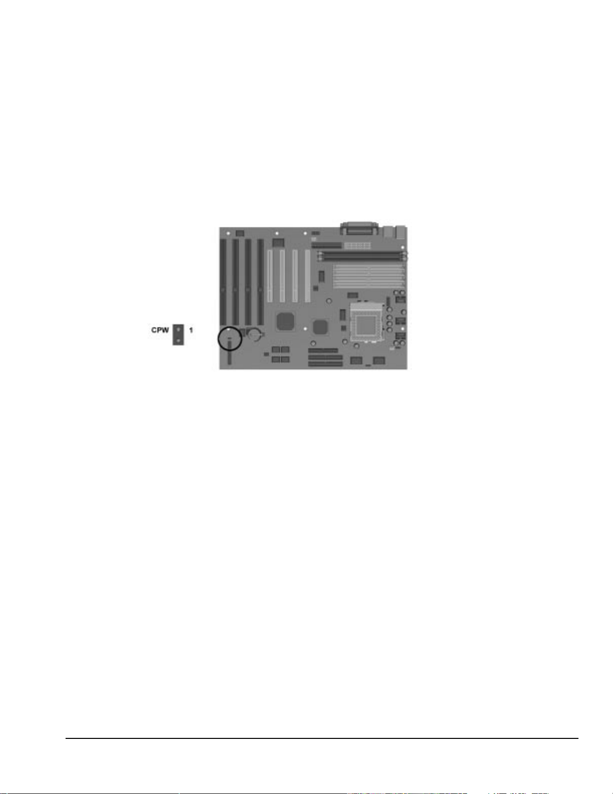
6.1.1 Power-On Password Jumpers (CPW)
If you forget your password, you cannot access the computer. You will need to disable the User
Password feature by setting the appropriate jumper on the system board. You will then be able to
access your computer.
1. Turn off the computer and any external devices.
2. Disconnect the power cord from the power outlet and any external devices from the computer.
3. Remove the computer cover.
4. Locate Jumper CPW.
Figure 6-2.
Locating the Password Jumper on the System Board
5. Remove the jumper from the single pin and reinstall it over both pins.
6. Leave the jumper on for approximately 60 seconds.
7. Remove the jumper from both pins and reinstall on a single pin.
8. Replace the computer cover.
9. Restart the computer.
Compaq Deskpro 1000 Series of Personal Computers 6-3
Page 73

6.1.2 Flash EPROM Type Selection (EP)
The EP1 and EP2 jumpers allow you to configure the Flash EPROM chip:
Table 6-2
EPROM Type Selection
Flash EPROM EP1 Pin Pairs EP2 Pin Pairs
1M * 1-2 1-2
2M* 2-3 2-3
*Default
When flashing an Intel-manufactured EPROM, move the EP jumper from pins 1-2 to 2-3. After
flashing is complete, return the jumper to pins 1-2.
To determine the EPROM manufacturer, locate the Award Flash EPROM chip located near the
external battery. Lift the black-on-silver label; the manufacturer’s name is printed on the chip.
6.1.3 CPU External Clock (Bus) Frequency (CLK)
The CLK1, CLK2, and CLK3 jumpers allow you to set the different CPU speed configurations.
Table 6-4 shows the jumper settings for the different bus speed configurations.
Table 6-3
CPU External Clock Frequency Settings
External (CPU/CLK) CLK1 Pin Pairs CLK2 Pin Pairs CLK3 Pin Pairs
66 MHz* 1-2 1-2 1-2
60 MHz 2-3 1-2 1-2
55 MHz 2-3 2-3 1-2
*Default setting.
6-4 Jumper Information
Page 74

6.1.4 CPU to SRAM Data Transacting Mode Selection (SRAM)
The SRAM jumper allows you to select the CPU to SRAM data read/write mode.
Table 6-4
SRAM Pin Pairs
Mode Pin Pair
Intel Burst (Default) for Intel Pentium CPUs, AMDK%, Cyrix, IBM*
Linear Burst 2-3
*Default setting.
1-2
6.1.5 Jumper Settings
The following table identifies the jumper settings for each processor frequency for the Pentium
with MMX Technology system boards:
CAUTION:
rated. Doing this could result in unreliable operation or processor damage.
CPU External CPU Clock Rate
Speed
(MHz)
Pentium with MMX Technology
233 66 1-2 1-2 1-2 1-2 1-2 1-2
200 66 1-2 1-2 1-2 1-2 2-3 1-2
166* 66 1-2 1-2 1-2 2-3 2-3 1-2
*Default setting
✎
Refer to Table 6-1 for a description of the CLK and FREQ jumpers.
Do not configure the system board to operate faster than the speed at which the processor is
(CPU/CLK)
(MHz) CLK1 CLK2 CLK3 FREQ1 FREQ2 FREQ3
6.1.6 Clearing Configuration
The computer's configuration (CMOS) may occasionally be corrupted. When it does, it is
necessary to clear the CMOS memory.
Table 6-5
Pentium with MMX Technology
System Board Jumper Settings
To clear and reset the configuration, run the CMOS Setup Utility described in Chapter 7,
“Utilities.”
6.1.7 Changing the Real-Time Clock (RTC) Battery
Refer to Chapter 5, “Removal and Replacement Procedures,” for complete instructions on
installing a replacement RTC battery.
Compaq Deskpro 1000 Series of Personal Computers 6-5
Page 75

6.2 Hard Drives
For more information about Compaq hard drives, refer to Appendix C in this guide.
6.2.1 1.6-GB IDE Hard Drive Jumper Settings
The jumper settings for the 1.6-GB EIDE hard drive are shown below.
Figure 6-3.
1.6-GB EIDE Hard Drive Jumper Settings
Seagate EIDE
Drive Application Jumpers
Single drive 5 to 6
Primary drive 5 to 6 and 3 to 4
Secondary drive no connection
Cable Select 3 to 4
Table 6.6
Hard Drive Jumper Settings
6-6 Jumper Information
Page 76

chapter
7
U
TILITIES
7.1 CMOS Setup Utility
7.1.1 Using the CMOS Setup Utility
Execute the CMOS Setup Utility when you upgrade or repair the computer, change the battery,
encounter a POST error, or choose to make a change to any of the default CMOS settings. To use
the utility:
1. Turn the computer off, then on.
2. Press the Delete key when the message “Press DEL to enter Setup” appears on the screen.
3. Use the arrow keys to highlight the setup feature you want to change.
4. Press Enter to open the selected setup feature.
5. Use the arrow keys to highlight the value you want to change.
6. Use the Page Up or Page Down keys to change the selected value.
7. Press Esc to return to the main menu.
8. Follow the on-screen instructions to save the changes and exit or to exit the utility without
saving any changes.
7.1.1.1 Safeguarding CMOS Settings
If you choose to change the default settings, you will want to restore those settings if the CMOS is
ever corrupted or the battery loses power.
To safeguard these settings, write them down, make a print screen of each CMOS setup page, or
use third-party CMOS rescue software to store the settings in a file on a write-protected diskette.
7.1.1.2 Restoring CMOS Settings
If you are able to access the CMOS Setup Utility, reload the BIOS defaults available in the CMOS
Setup Utility or restore the safeguarded settings stored on the write-protected diskettes.
If you are unable to access the CMOS Setup Utility, remove the battery for about five minutes,
then return it to restore the default settings. See Chapter 5, “Removal and Replacement
Procedures.”
7.1.2 Important CMOS Settings
7.1.2.1 Standard CMOS Setup
You can change the following settings in Standard CMOS Setup:
Date and time
Floppy disk drive types for drive A: and B:
Compaq Deskpro 1000 Series of Personal Computers 7-1
Page 77

Floppy mode support
Bootup video display mode
POST error handling selections
Hard disk configurations
✎
7.1.2.2 BIOS Features Setup
The BIOS features have already been preset at the factory, and users are advised not to run the
BIOS and Chipset Features Setup programs. Improper setup may cause the system to fail.
You can set Hard Disk Type to Auto to automatically detect the drive type.
However, if you choose to not use Auto, do a screen print screen or make a note of
the hard disk configuration settings for every hard drive on your computer so that
you can reenter these values if CMOS becomes corrupted.
7.1.3 Passwords
The supervisor and user passwords limit access to different functions of the computer.
The supervisor password protects the system configuration settings from unauthorized
modification. The user password prevents unauthorized access to data stored on the computer or
computer network.
Under the BIOS Feature Setup, you have the option to be prompted for a password every time you
start the computer or only when you enter the CMOS Setup Utility. Select an option under the
BIOS Feature Setup to be prompted for the:
Supervisor Password every time you try to start the CMOS Setup Utility and be prompted
for the User Password every time you turn on the computer. Select System under the
Security Option field.
User password only when you turn on the computer. Select Setup under the Security
Option field.
7.1.3.1 Establishing a Password
1. From Setup, select the Supervisor Password or User Password option.
2. Enter the password.
3. You will be asked to confirm the password. Retype the password and press
✎
7.1.3.2 Entering a Password
When prompted, enter your current password.
✎
7.1.3.3 Disabling a Password
1. From Setup, select the Supervisor Password or User Password that you want to disable.
2. When you are prompted to enter the established password, press
7-2 Utilities
If necessary, you may press
password.
Type carefully; for security reasons, the characters you type do not appear on the
screen.
confirming the password is disabled.
Esc
to abort the password selection and not enter a
Enter.
A message appears
Enter
.
Page 78

7.1.3.4 Changing a Password
To change a password, complete the following steps:
1. Disable the established password by pressing
2. Establish a new password by following the instructions in “Establishing a Password” in this
chapter.
7.1.3.5 Clearing a Password
If you forget your password, you cannot access the computer. You will need to disable the
password feature by setting the appropriate jumper on the system board. You will then be able to
access your computer.
1. Turn off the computer and any external devices.
2. Disconnect the power cord from the power outlet and any external devices from the computer.
3. Remove the computer cover.
4. Locate Jumper CPW.
Enter
when prompted for the current password.
Figure 7-1.
5. Remove the jumper from the single pin and reinstall it over both pins.
6. Leave the jumper on for approximately 60 seconds.
7. Remove the jumper from both pins and reinstall on a single pin.
8. Replace the computer cover.
9. Restart the computer.
Locating the Password Jumper on the System Board
7.1.4 IDE HDD Auto Detection
The IDE HDD Auto Detection feature automatically configures the new hard drive, and allows
you to set the parameters of up to four IDE hard drives. The option with (Y) is recommended by
the system BIOS. You may also key in your own parameters instead of having the system BIOS
set them for you. After modifying the settings, press the Esc key to return the main menu. For
confirmation, enter the Standard CMOS Setup feature.
7.1.5 Save and Exit Setup
To save the changed CMOS settings:
Compaq Deskpro 1000 Series of Personal Computers 7-3
Page 79

1. Press Esc to return to the main menu.
2. Press “Save and Exit Setup” The message “SAVE to CMOS and EXIT (Y/N)?” will appear at
the center of the screen.
3. Press Y [
4. Press F10 (Save and Exit Setup) then press Y [
If you do not make any changes or if you want to cancel the changes you just made, see “Exit
Without Saving,” in this chapter.
] to save the changes, or
Enter
7.1.6 Exit Without Saving
If you want to cancel the changes you made to CMOS:
1. Press Esc to return to the main menu.
2. Select “Exit Without Saving.” [Enter].The message “Quit Without Saving?” appears on the
screen.
3. Press Y [Enter] to exit without saving the changes you just made.
7.2 Upgrading the BIOS
WARNING:
!
1. Create a bootable floppy diskette.
2. Place the bootable diskette containing the BIOS file and the Flash Utility in drive A, and reboot
the system in MS-DOS (Version 6.22 is preferred).
Do not turn off or reset the computer during the flash process. It will corrupt the BIOS data.
Enter
].
3. At the A: prompt, type the Flash BIOS utility and the BIOS file with its extension. For
example:
flash531 615J900.bin
4. At the Flash Memory Write menu:
To save the current BIOS settings, select Y then type the current BIOS name and the extension
after FILE NAME TO SAVE. For example:
613J900.bin
If you do not want to save your current BIOS, select N.
5. Confirm the selection.
6. When the screen displays the message Power Off or Reset the System, remove the diskette,
hold down the END key, and restart the system.
✎
You must depress the End key prior to power-on until you enter CMOS setup. If
this is not done when restarting the system after upgrading the BIOS, the system
will not start properly.
7.3 Configuring Windows Display and Monitor
When you first set up the computer and monitor, the Windows 95 operating system detects the
monitor type, selects the best display configuration, and installs the appropriate display drivers.
7-4 Utilities
Page 80

This automated setup is referred to as Plug and Play; there are no switches to set or manual
procedures to follow; just plug it in.
✎
A monitor with Asset Control is required for the Plug and Play setup to work. If
you do not have a Plug and Play monitor, you can set up the display manually.
7.3.1 Supported Resolutions
Resolutions supported by the graphics controller installed on the Compaq LGX Personal
Computer are presented in Chapter 8, “Specifications.”
7.3.2 Changing Monitor Type Manually in Windows 95
If you are using Windows 95, the operating system automatically recognizes all Plug and Play
monitors. If you are not using a Plug and Play monitor, select Display in the Control Panel and.
follow the on-screen instructions to make the change.
7.3.3 Setting Graphics Resolution
The quality of the picture you see depends on the resolution of the monitor and the number of colors that are
displayed. Although the setup utility automatically selects the display configuration, you can manually change
the resolution to match a software program or to suit personal preferences. Select Display in the Control Panel
and. follow the on-screen instructions to make the change.
7.3.4 Establishing a Password in Windows 95
To establish a password in Windows 95, complete the following steps:
1. Go to the Control Panel.
2. Double-click the Passwords icon and follow the instruction to set a new password.
7.4 Diagnostics Software
✎
Diagnostics software is not included with this computer. Compaq diagnostics
software Version PC 10.25A, is available from your Compaq authorized dealer,
reseller, or service provider, or the Compaq world-wide web site at
WWW.COMPAQ.COM. Diagnostics software is also available from third-party
diagnostics software provider.
Compaq Deskpro 1000 Series of Personal Computers 7-5
Page 81

chapter
8
S
PECIFICATIONS
This chapter provides physical, environmental, and performance specifications for the computer,
keyboard, and mass storage devices.
8.1 System
Dimensions
Height
Width
Length
Weight 10.40 kg 22.9 lb
Power Supply
Operating Voltage Range
Rated Voltage Range
Rated Line Frequency
Rated Input Current (maximum) 3 A 6 A
Power Output 200 W 200 W
Environmental Requirements
Temperature
Operating
Shipping
Humidity (noncondensing)
Operating
Nonoperating
Maximum Altitude (unpressurized)
Operating
Nonoperating
Heat Dissipation (nominal) 3.23 kg-cal/min 770 Btu/hr
Table 8-1
System Specifications
Metric U. S.
16.51 cm
42.88 cm
41.28 cm
180-264 VAC
200-240 VAC
50 - 60 Hz
10° to 35°C
-20° to 60°C
8% to 90%
5% to 95%
3048 m
9144 m
6.5 in
16.88 in
16.25 in
90-132 VAC
100-120 VAC
50 - 60 Hz
50° to 95°F
-4° to 140°F
8% to 90%
5% to 95%
10,000 ft
30,000 ft
Compaq Deskpro 1000 Series of Personal Computers 8-1
Page 82

Table 8-2
System Interrupts
Hardware IRQ System Function
IRQ 0 Timer Interrupt (Not on ISA Bus)
IRQ 1 Keyboard (Not on ISA Bus)
IRQ 2 Interrupt Controller Cascade (Not on ISA Bus)
IRQ 3 Serial Port (COM 2)
IRQ 4 Serial Port (COM 1)
IRQ 5 Enhanced Business Audio*
IRQ 6 Diskette Drive
IRQ 7 Parallel Port (LPT 1)
IRQ 8 Real-Time Clock (Not on ISA Bus)
IRQ 9 Free for PCI Use
IRQ 10 Free for PCI Use
IRQ 11 PCI Interrupt
IRQ 12 Mouse
IRQ 13 Coprocessor (Not on ISA Bus)
IRQ 14 IDE Interface (Hard Disk and Primary IDE Drive)
IRQ 15 CD-ROM (Secondary IDE/Drive)
*Default configuration; other configurations = IRQ7, IRQ9, IRQ10, None
Table 8-3
System DMA
Hardware DMA System Function
DMA 0 Unused
DMA 1 Business Audio (Default; Alternate = DMA0, DMA3, None)
DMA 2 Diskette Drive
DMA 3 ECP Parallel Port LPT1 (Default; Alternate = DMA 0)
DMA 4 DMA Controller Cascading (Not on ISA Bus)
DMA 5 Unused
DMA 6 Unused
DMA 7 Unused
8-2 Specifications
Page 83

Table 8-4
System I/O
I/O Address (Hex) * System Function (Shipping Configuration)
000 - 00F 8237 DMA Controller #1
020 - 02F 8259A Master Programmable Interrupt Controller
040 - 05F Programmable Internal Timer
060 - 06F Keyboard Controller
070 - 071 System CMOS/RTC, also NMI Enable/Disable
080 Manufacture System Check Point Port
081 - 09F DMA Page Registers
0A0 - 0BF Second 8259 Programmable Interrupt Controller
0C0 - 0DF DMA Controller #2
0F0 - 0FF Numeric Data Processor
170 – 17F Secondary IDE Controller
1F0 - 1FF Primary IDE Controller
200 Gameport (only if you have a sound card installed)
201 Gameport (only if you have a sound card installed)
278 - 27F Third Parallel Port
2E8 - 2EF COM4 (if you set COM4)
2F8 - 2FF COM2
370 - 377 Secondary Diskette Controller (if present))
378 - 37F Second Parallel Port
3B0 - 3BF Monochrome Display Adapter/Primary Parallel Port
3C0 - 3CF EGA/VGA Adapter
3D0 - 3DF Color Graphic Adapter
3E8 - 3EF COM3 (if you set COM3)
3F0 - 3F7 Primary Diskette Controller
3F8 - 3FF COM1
04D0 - 04D1 PIC Edge/Level Control Register
0CF8 - 0CFF PCI Configuration Register
6000 - FFFF PCI Device I/O Space
*All I/O addresses below 100 are reserved by the chipset even if they are not used.
Compaq Deskpro 1000 Series of Personal Computers 8-3
Page 84

Table 8-5
System Memory Map
Size* Memory Address (Hex) System Function
64 KB FFFFFFFFh to FFFF0000h System ROM
1504 MB FDFFFFFFh to A0000000h PCI Memory Expansion
510 MB 1FF00000h to 00100000h System Memory
64 K 000FFFFFh to 000F0000h System ROM
64 KB 000EFFFFh to 000E0000h Reserved
96 KB 000DFFFFh to 000C8000h Reserved
32 KB 000C7FFFh to 000C0000h Video ROM
128 KB 000BFFFFh to 000A0000h Video RAM
640 KB 0009FFFFh to 00000000h Base Memory
*All memory above the first 256 MB is non-cacheable. All PCI memory is non-cacheable.
8-4 Specifications
Page 85

8.2 Drives
Size and Capacity
Size (cm)
Size (in)
High Density (MB)
Low Density (KB)
Light Green
Height One-third
Bytes per Sector 512
Sectors per Track
High Density
Low Density
Tracks per Side
High Density
Low Density
Read/Write Heads 2
Average Seek Time (Mb/s)
Track-to-Track (high/low)
Average (high/low)
Latency Average (ms)
Table 8-6
Diskette Drive
1.44 MB
8.9
3.5
1.44
720
18
9
80
80
3/3
94/94
100
Compaq Deskpro 1000 Series of Personal Computers 8-5
Page 86

EIDE Hard Drive
1.6-GB
Formatted Capacity
Physical (MB)
Logical (MB)
Compaq Spare Part Number 333816-001
Drive Type 65
Transfer Rate
Interface (Mbytes/sec) 16.7
Typical Seek Time (including
settling)
Single Track (ms)
Average (ms)
Full Stroke (ms)
Disk Rotational Speed (rpm) 5400
Cylinders
Logical 3390
Data Heads
Logical 16
Sectors per Track
Logical 63
Buffer Size (KB) 128
1624.7
1624.7
3.0
13.0
22.0
Table 8-7
8-6 Specifications
Page 87

8.3 Mouse
Dimensions
Height
Length
Width
Weight 130 g 4.59 oz
Base Resolution 400 dpi 400 dpi
Tracking Speed (maximum) 25 cm/sec 10 in/sec
Temperature
Operating
Storage
Lifetime
Mechanical
Switch
Relative Humidity 10% to 90%, noncondensing 10% to 90%, noncondensing
ESD No soft errors through 10 kV;
Table 8-8
2-Button Mouse
Metric U.S.
3.4 cm
11.3 cm
6.0 cm
0°C to 40°C
-20°C to 60°C
Exceeds 483 km
Exceeds 1 million operations
No hard errors through 15 kV; specific performance depends on host system
1.34 in
4.45 in
2.36 in
32°F to 104°F
-4°F to 140°F
Exceeds 300 miles
Exceeds 1 million operations
8.4 Keyboard
Dimensions
Height
Length
Width
Weight 0.9 kg 1.98 lb
Table 8-9
Compaq Enhanced Keyboard
Metric U.S.
4.0 cm
45.6 cm
16.8 cm
1.58 in
17.95 in
6.63 in
Compaq Deskpro 1000 Series of Personal Computers 8-7
Page 88

8.5 Supported Graphics Resolutions
Table 8-10
Supported Graphics Resolutions
S3 Trio64V2/DX Graphics Card
Resolution 1-MB DRAM 2-MB DRAM
1280 × 1024 16 @ 75 Hz 256 @ 75 Hz
1024 × 768 256 @ 85 Hz 64K @ 75 Hz
800 × 600 655K @ 85 Hz 16.7M @ 75 Hz
640 × 480 655K @ 85 Hz 16.7M @ 75 Hz
8-8 Specifications
Page 89

appendix
A
C
ONNECTOR PIN ASSIGNMENTS
This appendix contains the pin assignments for all external connectors:
Connector Pin Signal
65
43
KEY
1
2
1
2
3
4
5
6
Table A-1
Keyboard
Data
Unused
Ground
+5 VDC
Clock
Unused
Table A-2
Mouse
Connector Pin Signal
6
5
4
3
KEY
1
2
1
2
3
4
5
6
Data
Unused
Ground
+5 VDC
Clock
Unused
Compaq Deskpro 1000 Series of Personal Computers A-1
Page 90

Table A-3
Parallel Interface
Connector Pin Signal
13 12
11 10 89
2425
23 22 21 20
7
5643
1819 1617
15 14
12
1
2
3
4
5
6
7
8
9
10
11
12
13
14
15
16
17
18-25
Strobe#
Data Bit 0
Data Bit 1
Data Bit 2
Data Bit 3
Data Bit 4
Data Bit 5
Data Bit 6
Data Bit 7
Acknowledge#
Busy
Paper End
Select
Auto Linefeed#
Error#
Initialize Printer#
Select IN#
Signal Ground
Table A-4
Serial Interface
Connector Pin Signal
16283
7
1
54
9
2
3
4
5
6
7
8
9
Carrier Detect
Receive Data#
Transmit Data#
Data Terminal Ready
Signal Ground
Data Set Ready
Request to Send
Clear to Send
Ring Indicator
A-2 Connector Pin Assignments
Page 91

Table A-5
VGA Monitor
Connector Pin Signal
45
123
9
10
78
13 12
6
15 14 11
*For DDC support (I2C monitors)
1
2
3
4
5
6
7
8
9
10
11
12
13
14
15
Red Analog
Green Analog
Blue Analog
Monitor ID Bit2
Ground
Ground Analog
Ground Analog
Ground Analog
Not Connected
Ground
Monitor ID Bit 0
Bidirectional Data (SDA)*
Horizontal Sync
Vertical Sync
Data Clock (SCL)*
Table A-6
USB Connector
Connector Pin Signal
1234
1
2
3
4
VCC
- Data
+ Data
Ground
Compaq Deskpro 1000 Series of Personal Computers A-3
Page 92

Table A-7
IDE Drive Cable
49
50
1
2
Pin Signal Pin Signal
1 RESDRV 26 GND
2 GND 27 IOCHRDY
3 D07 28 CABLE SELECT
4 D08 29 DAK
5 D06 30 GND
6 D09 31 IRQ
7 D05 32 IO16
8 D10 33 A1
9 D04 34 PDIAG
10 D11 35 A0
11 D03 36 A2
12 D12 37 CS1FX
13 D02 38 CS3FX
14 D13 39 DASP
15 D01 40 GND
16 D14 41 AUDIO_R
17 D00 42 AUDIO_L
18 D15 43 A_GND_R
19 GND 44 A_GND_L
20 (KEY) 45 +5VMOT1
21 DREQ 46 +5VMOT2
22 GND 47 +5VMOT3
23 IOW 48 +5VMOT4
24 GND 49 +5VMLOG1
25 IOR 50 +5VMLOG2
A-4 Connector Pin Assignments
Page 93

appendix
B
P
OWER CORD SET REQUIREMENTS
The voltage select switch feature on the computer permits it to operate from any line voltage between
100-120 or 220-240 volts AC.
The power cord set received with the computer meets the requirements for use in the country where
you purchased the equipment.
Power cord sets for use in other countries must meet the requirements of the country where you use
the computer. For more information on power cord set requirements, contact your authorized
Compaq dealer, reseller, or service provider.
General Requirements
The requirements listed below are applicable to all countries:
1. The length of the power cord set must be at least 1.8 m (6.00 feet) and a maximum of
3.0 m (9.75 feet).
2. All power cord sets must be approved by an acceptable accredited agency responsible for
evaluation in the country where the power cord set will be used.
3. The power cord set must have a minimum current capacity of 10A and a nominal voltage rating
of 125 or 250 volts AC, as required by each country’s power system.
4. The appliance coupler must meet the mechanical configuration of an EN 60 320/IEC 320
Standard Sheet C13 connector, for mating with appliance inlet on the Switch Box.
Compaq Deskpro 1000 Series of Personal Computers B-1
Page 94

Country-Specific Requirements
Power Cord Set Requirements—By Country
Country Accredited Agency Applicable Note Numbers
Australia EANSW 1
Austria OVE 1
Belgium CEBC 1
Canada CSA 2
Denmark DEMKO 1
Finland SETI 1
France UTE 1
Germany VDE 1
Italy IMQ 1
Japan MITI 3
Norway NEMKO 1
Sweden SEMKO 1
Switzerland SEV 1
United Kingdom BSI 1
United States UL 2
NOTES:
1. The flexible cord must be <HAR> Type HO5VV-F, 3-conductor, 1.0 mm
2
conductor size.
Power cord set fittings (appliance coupler and wall plug) must bear the certification mark of the
agency responsible for evaluation in the country where it will be used.
2. The flexible cord must be Type SJT or equivalent, No. 18 AWG, 3-conductor. The wall plug
must be a two-pole grounding type with a NEMA 5-15P (15A, 125V) or NEMA 6-15P (15A
250V) configuration.
3. The appliance coupler, flexible cord, and wall plug must bear a "T" mark and registration
number in accordance with the Japanese Dentori Law. The flexible cord must be Type VCT or
VCTF, 3-conductor, 0.75 mm
2
conductor size. The wall plug must be a two-pole grounding
type with a Japanese Industrial Standard C8303 (15A, 125V) configuration.
B-2 Power Cord Set Requirements
Page 95

appendix
C
H
ARD DRIVES
Compaq Computer Corporation uses IDE hard disk drives that conform to two different
primary/secondary implementations. These are Conner mode and ATA-compatible mode. These
two modes are incompatible with one another.
Device 0/Device 1 Relationship
A device 0/device 1 relationship exists when there are two hard drives connected to a single port.
In this situation, one drive must be designated as the device 0, or primary, drive and the other as
the device 1, or secondary, drive. This designation is necessary because both drives cannot work
simultaneously.
Cable Select
The Compaq Deskpro 1000 Series of Personal Computers uses cable-select technology for
identifying Device 0 (primary) and Device 1 (secondary) IDE hard drives. Check that the jumpers
on the IDE hard drive are set properly for cable-select installation. Always check the label on the
drives or check Chapter 6 of this manual when a new drive is added to verify that the jumper
settings are set correctly.
Cable select may not function properly if drives other than those supported by Compaq are
installed.
The second drive on a cable-select cable can be a CD-ROM drive. However, the CD-ROM
drive must be installed in the device 1 position if a hard drive is installed on the same
cable. Ensure that both drives are set for cable-select configuration. See Chapter 6 for more
information.
If two drives are already connected to the primary IDE controller and an additional drive is
to be installed, the secondary IDE controller must be enabled. The secondary IDE
controller can be enabled by checking this option after opening the Advanced box in the
Mass Storage group of F10 Computer Setup. See Chapter 7 for more information.
When more than two drives are installed, drive performances are best when the two faster
drives are connected to the primary IDE controller and the slower drive is connected to the
secondary IDE controller.
A hard drive is installed and configured more quickly when it has first been formatted.
If your new drive includes the cable-select feature, no jumper setting changes are required.
Refer to the documentation supplied with the cable for instructions on using the cable
select feature. If you install a third-party hard drive, you will need to purchase a jumper
cable (spare part number 247568-001) from Compaq Computer Corporation.
IntelliSafe - SMART
The IntelliSafe IDE hard drives for the Compaq Deskpro 1000 Series of Personal Computers have
built-in drive failure prediction that warns the user or the network administrator of an impending
failure or crash of the hard drive.
Compaq Deskpro 1000 Series of Personal Computers C-1
Page 96

Automatic Soft-Drive Types
An automatic soft-drive type is a mechanism where the system ROM and Computer Setup provide
support for IDE hard drives that are not supported in the hard drive parameter table. Computer
Setup automatically builds a soft-drive type when it finds that a hard drive is not in the hard drive
parameter table.
The soft-drive types assign according to the table below:
Table C-1
Soft-Drive Type Assignments
Drive Hard Drive Type Controller
0 65 Primary
1 66 Primary
0 68 Secondary
1 15 Secondary
For hard drives that are greater than 528 MB, the system automatically translates the hard drive
parameter for DOS by logically halving the cylinders and doubling the heads. This allows DOS to
access greater than 528 MB. The translated hard drive parameters are put into the hard drive
parameter table in the shadow RAM copy of the system ROM. When using any operating system
other than DOS, you must use the Compaq User Diagnostic diskette to set up the hard drive
parameter table without translation.
C-2 Hard Drives
Page 97

A
Alt key, 1-8
architecture, 1-3
B
battery
internal, 1-4
bezel
illustrated, 3-2
spare part number, 3-2
BIOS
features setup, 7-2
upgrading, 7-4
boxes, shipping, 3-9
C
cable select
description, C-1
cables, 4-5
and connectors, 4-5
illustrated, 3-4
removal and replacement,
C-1
spare part numbers, 3-4
cache, 1-3
CD-ROM cable
connector pin assignments,
A-4
CD-ROM drive
troubleshooting, 2-12
chassis
illustrated, 3-2
chipset, 1-3
clearing configuration, 6-5
clearing the password, 2-5
CMOS settings
restoring, 7-1
safeguarding, 7-1
CMOS setup
exit without saving, 7-4
IDE HDD auto detection, 7-3
save and exit setup, 7-3
Index
standard settings, 7-1
CMOS Setup Utility, 2-4, 7-1
using, 7-1
Computer Checkup (TEST),
2-5
connector pin assignments
CD-ROM cable, A-4
USB, A-3
connectors, 4-5, A-1
connectors, rear panel, 1-7
controls
front panel, 1-5
CPU External Clock
Frequency Settings, 6-4
Ctrl key, 1-8
D
design overview, 1-4
device 0/device 1 relationship,
C-1
diagnostics
running, 2-5
DIMM
installing, 5-12
disassembly/assembly
sequence, 5-2
diskette drive
eject button, 1-5
optional, 1-3
standard, 1-3
troubleshooting, 2-7
display
troubleshooting, 2-8
documentation, viii
documentation, spare part
numbers, 3-9
drive bay bezel
illustrated, 3-2
drive bays, 1-3
drive cage
removal, 5-25
spare part number, 3-2
drive positions, 1-6
E
electrostatic damage,
preventing, 4-2
electrostatic discharge, 4-1
enhanced keyboard, 1-4
EP
Flash EPROM, 6-4
error messages, 2-2
ESD, 4-1
expansion slots, 1-3, 5-4
F
fan
power supply, 1-4
features, 1-3
flash EPROM, 6-4
front bezel
illustrated, 3-2
spare part number, 3-2
G
generating static, 4-1
graphics
resolutions, 1-3
setting resolution, 7-5
graphics memory board
spare part number, 3-5
grounding
electrical, viii
equipment, 4-3
methods, 4-2
workstations, 4-3
H
hard drive
IntelliSafe, C-1
optional, 1-3
soft-drive type assignments,
C-2
standard, 1-3
troubleshooting, 2-10
hardware
Index I-1
Page 98

troubleshooting, 2-11
hardware installation
troubleshooting, 2-11
I
I/O ports, 1-3
Illustrated Parts Map, viii
information, locating
additional, viii
IntelliSafe, C-1
J
jumper
CLK, 6-4
CPW, 6-3
EP, 6-4
password, 6-3
SRAM, 6-5
jumper cable, C-1
jumper locations
1.62-GB IDE hard drive, 6-6
jumper settings
1.62-GB IDE hard drive, 6-6
system board, 6-5
jumpers
system board, 6-1
K
keyboard, 1-8
keyboard
connector, A-1
enhanced, 1-4, 1-8
illustrated, 3-6
spare part numbers, 3-6
L
LED Cables, 5-20
LEDs, 1-5
illustrated, 3-4
M
map, spare parts, viii
mass storage devices
removal, 5-24
spare part numbers, 3-3
materials, static preventing,
4-4
memory
configuration, 5-10
DIMM, 1-3
installing DIMM, 5-12
installing SIMM, 5-11
SIMM, 1-3
troubleshooting, 2-12
miscellaneous hardware
spare parts, 3-7
miscellaneous plastics
illustrated, 3-8
spare part number, 3-8
models, 1-2
monitors
connector pin assignments,
A-3
mouse, 1-4
connector pin assignments,
A-1
O
operating system
standard, 1-4
P
parallel interface pin
assignments, A-2
password
changing, 7-3
clearing, 7-3
disabling, 7-2
entering, 7-2
establishing, 7-2
supervisor, 7-2
user, 7-2
pin assignments
CD-ROM cable, A-4
keyboard connector, A-1
mouse connector, A-1
parallel interface connector,
A-2
serial interface, A-2
USB, A-3
VGA monitor connector, A-3
plastic parts, 4-5
Plug and Play
problems, 2-11
power
troubleshooting, 2-6
power cord set requirements
by country, B-2
general, B-1
power supply, 1-4
illustrated, 3-2
spare part number, 3-2
power switch, 1-5
Power-On Self-Test (POST)
function, 2-1
messages, 2-2
preloaded software, 1-5
preparation for disassembly,
5-3
preventing electrostatic
damage, 4-2
printer
troubleshooting, 2-9
processor, 1-3
spare part number, 3-5
Q
QuickFind, viii
R
rear panel connectors, 1-7
removal and replacement
procedures, 5-1
remove
3.5-inch drive, 5-26
5.25-inch drive, 5-27
battery, 5-23
bezel blank, 5-22
drive cage, 5-25
expansion board guide, 5-6
expansion boards, 5-4
feet, 5-3
front bezel assembly, 5-18
graphics memory, 5-8
LED cables, 5-20
LED retainer assembly, 5-19
mass storage devices, 5-24
memory modules, 5-9
microprocessor, 5-14, 5-16
power button, 5-21
power supply, 5-13
system board, 5-7
system unit cover, 5-4
repair warning, viii
resolutions supported, 7-5
ROM BIOS, 1-3
S
Safety & Comfort guide, viii
screws, 4-5
serial
number, viii
I-2 Index
Page 99

serial interface
pin assignments, A-2
serial number, 5-1
service considerations, 4-4
setup password, 7-2
changing, 7-3
clearing, 7-3
disabling, 7-2
entering, 7-2
establishing, 7-2
shipping boxes
spare part numbers, 3-9
SIMM
installing, 5-11
spare part number, 3-5
soft-drive type assignments,
C-2
software
preloaded, 1-5
required for service, 4-4
spare parts
map, viii
speaker
internal, 1-4
SRAM
CPU to SRAM data
transacting mode selection,
6-5
standard and optional boards
spare parts, 3-5
static shielding protection
levels, 4-2
static, generating, 4-1
supervisor password, 7-2
supported resolutions, 7-5
switch settings, 6-5
symbols, vii
system
design, 1-4
serial number, viii
system board jumpers, 6-1
CLK, 6-4
CPW, 6-3
EP, 6-4
locating, 6-2
SRAM, 6-5
system memory
configuration, 5-10
system unit
illustrated, 3-2
spare part numbers, 3-2
T
Technical Reference Guide,
viii
tools required for service, 4-4
troubleshooting without
diagnostics
CD-ROM, 2-12
diskette drive, 2-7
display, 2-8
hard drive, 2-10
hardware installation, 2-11
hardware installation, 2-11
memory, 2-12
minor problems, 2-5
power, 2-6
printer, 2-9
typical electrostatic voltages,
4-1
U
unit cover
illustrated, 3-2
Upgrading the BIOS, 7-4
USB connector pin
assignments, A-3
user password, 7-2
V
ventilation, viii
voltages, typical electrostatic,
4-1
W
Windows
configuring display, 7-4
Logo key, 1-8
Index I-3
 Loading...