

Page 1
INSTALLATION AND OPERATION MANUAL
CNVETX1
VIDEO ENCODER/DECODER UNIT
The ComNet™ CNVETX1 is a single-channel, camera-ready H.264/MPEG-4/MPEG-2,
and MJPEG intelligent video server/video encoder or decoder unit, with video quality
of up to D1 at 1 to 30 FPS, and dual or triple encoding/streaming. The CNVETX1
is industrially hardened for deployment in unconditioned/out-of-plant operating
environments. It is user-configurable for use as an encoder or decoder, or the video
decoding may be done with third party decoding software. Incorporating a distributed
intelligent video architecture, analog/composite video NTSC or PAL CCTV cameras
with IP or full-duplex serial data pan-tilt-zoom control may be easily integrated
onto any IP network. Full command and control of the various video encoding
parameters are provided, including resolution, bit rate, and frame rate. A full-duplex
mono audio channel is included. The ComNet IVS (Integrated Video Server) allows
for managing multiple simultaneous video streaming, and enables onboard video
content management.
Page 2

INSTALLATION AND OPERATION MANUAL CNVETX1
About This Guide
This guide is intended for different users such as engineers, integrators, developers, IT managers,
and technicians.
It assumes that users have some PC competence and are familiar with Microsoft Windows
operating systems and web browsers such as Windows Internet Explorer and Mozilla Firefox, as
well as have knowledge of the following:
» Installation of electronic equipment
» Electrical regulations and guidelines
» Knowledge of Local Area Network technology
This document includes the following sections:
Introduction describes the system hardware and software.
Installation describes how to install the hardware.
Getting Started includes the system requirements, installation overview and a general
description of the functionalities of the user interface.
Monitoring Live Video contains instructions for operating live monitoring and the PTZ camera.
Audio/Video Configuration describes setting the audio/video configuration and how to control
the streaming parameters and view the active running streams.
Video Analytics includes procedures for video analytics configuration activation and operation.
Managing System Settings includes procedures for various system settings and management
tasks.
Board Configuration via Serial Port describes how you can configure the board via a serial port.
RTP/RTSP Video Node describes the RTSP URI format.
Related Documentation
The following documentation is also available:
» CNVETX1 Datasheet
» CNVETX1 Quick Start Guide
TECH SUPPORT: 1.888.678.9427
INS_CNVETX1_REV– 06/10/13 PAGE 2
Page 3

INSTALLATION AND OPERATION MANUAL CNVETX1
About ComNet
ComNet develops and markets the next generation of video solutions for the CCTV, defense, and
homeland security markets. At the core of ComNet’s solutions are a variety of high-end video
servers and the ComNet IVS integrated web server, which provide the industry with a standard
platform for analytics and security management systems enabling leading performance, compact
and cost effective solutions.
ComNet’s products are available in commercial and rugged form.
Website
For information on ComNet’s entire product line, please visit the ComNet website at
http://www.comnet.net
Support
For any questions or technical assistance, please contact your sales person (sales@comnet.net) or
the customer service support center (techsupport@comnet.net)
Safety
» Only ComNet service personnel can service the equipment. Please contact ComNet Technical
Support.
» The equipment should be installed in locations with controlled access, or other means of
security, and controlled by persons of authority.
TECH SUPPORT: 1.888.678.9427
INS_CNVETX1_REV– 06/10/13 PAGE 3
Page 4

INSTALLATION AND OPERATION MANUAL CNVETX1
Contents
About This Guide 2
Related Documentation 2
About ComNet 3
Website 3
Safety 3
Overview 6
Legal Information 6
Abbreviations List 7
Introduction 9
Software Features 10
Performance (Encoder Operation Mode) 11
Hardware Overview 12
Hardware Features 12
Connecting the Cables 15
CNVETX1 Technical Specifications 17
Getting Started 18
System Requirements 18
Installation 18
Monitoring Live Video 25
Panning a PTZ Camera 35
Zooming the Camera 39
Focusing the Camera 41
Managing System Settings 73
Network Settings 78
Using the ComNet Site Control Utility 80
Changing the IP Address 81
TECH SUPPORT: 1.888.678.9427
Changing the User Password 84
Setting up the Clock 85
Configuring the SNMP Settings 87
Configuring Operation Mode 89
Updating the Firmware 90
INS_CNVETX1_REV– 06/10/13 PAGE 4
Page 5

INSTALLATION AND OPERATION MANUAL CNVETX1
Contents, continued
System Administration 91
Resetting the User Password 92
Changing System Administrator Password 93
Reset to Factory Defaults 94
Change Web Interface Language 97
Reset 98
Configuring Local Storage 99
Media Files 100
SD Maintenance 101
Decoding Video 102
Video Type 103
Display Configuration 111
Board Configuration via Serial Port 112
RTSP URI Format 117
General Video Parameters 118
MJPEG Parameter 118
MPEG-2 Parameters 118
MPEG-4 Parameters 119
H.264 Parameters 119
General Audio Parameters 120
PCMA and PCMU Parameters 120
Multicast Parameters 120
TECH SUPPORT: 1.888.678.9427
INS_CNVETX1_REV– 06/10/13 PAGE 5
Page 6

INSTALLATION AND OPERATION MANUAL CNVETX1
Overview
Legal Information
No part of this document may be reproduced or transmitted in any form or by any means,
electronic and mechanical, for any purpose, without the express written permission of ComNet.
Copyright
Copyright © 2013 ComNet. All rights reserved.
Disclaimer
ComNet reserves the right to make changes in specifications at any time without notice. The
information furnished by ComNet in this material is believed to be accurate and reliable. However,
ComNet assumes no responsibility for its use.
Trademarks
Windows, the Windows logo, Windows 98/2000/Millenium/XP/Vista, and Windows NT, are either
registered trademarks or trademarks of Microsoft Corporation in the United States and/or other
countries.
Apple, the Apple logo, and QuickTime are trademarks of Apple Computer, Inc., registered in the
U.S. and other countries.
Linux is a registered trademark of Linus Torvalds.
Other product and company names mentioned herein may be the trademarks of their respective
owners.
Java is a registered trademark of Sun Microsystems, Inc. All rights reserved.
TECH SUPPORT: 1.888.678.9427
INS_CNVETX1_REV– 06/10/13 PAGE 6
Page 7

INSTALLATION AND OPERATION MANUAL CNVETX1
Abbreviations List
The following terms and abbreviations are used throughout the document.
Table 1: Abbreviation Table
API Application Programming Interface
CBR Constant bit rate
CCTV Closed Circuit Television
CIF Constant Intermediate Format 352 x 288
CVBS Color Video Blank Sync
CVBS Composite Video Baseband Signal
DDR Double data rate SDRAM memory
DHCP Dynamic Host Configuration Protocol
DNS Domain Name System
DPDT Double Pole Double Throw switch
DSP Digital Signal Processor
DST Daylight Savings Time
FOV Field of View
FPS Frames per Seconds
G.711 ITU-T standard for audio
GMT Greenwich Mean Time
GOP Group of Pictures
HTTP Hypertext Transfer Protocol
H.264 Standard for video compression
I-Frames Intra coded picture
IP Internet Protocol
IVS Intelligent Video Server
JPEG Joint Photographic Experts Group
LAN Local Area Network
LED Light Emitting Diode
MAC Media Access Control
MIC Microphone
MJPEG Motion JPEG
MMSE Multimedia Messaging Service Environment
MPEG Motion Picture Experts Group
MTU Maximum Transmission Unit
MPA Motion Picture Association
MP3 MPEG-1 Audio Layer 3
TECH SUPPORT: 1.888.678.9427
INS_CNVETX1_REV– 06/10/13 PAGE 7
Page 8

INSTALLATION AND OPERATION MANUAL CNVETX1
NTSC National Television Standards Committee
OSD On-Screen Display
PAL Phase Alternating Line
PCI Peripheral Component Interconnect
P-Frames Predictive coded picture
PTZ Pan Tilt Zoom
Q Quantization
QCIF Quarter CIF 176 x 144 video resolution
QVGA Quarter VGA 320 x 240 video resolution
RTP Real Time Transport Protocol
RTSP Real Time Streaming Protocol
RTP2 ComNet library communication protocol
SDK Software Development Kit
SNMP Simple Network Management Protocol
SNTP Synchronized Network Time Protocol
STDP Single Throw Double Pole
TTL Transistor-Transistor Logic
TCP Transmission Control Protocol
TCP/IP Internet protocol suite
UART Universal Asynchronous Receiver Transmitter
UDP Universal Datagram Protocol
URI Uniform Resource Identifier
URL Uniform Resource Locator
VBR Variable Bit rate
VGA Video Graphics Array
VSP Virtual Serial Port
XML Extensible markup Language
TECH SUPPORT: 1.888.678.9427
INS_CNVETX1_REV– 06/10/13 PAGE 8
Page 9
INSTALLATION AND OPERATION MANUAL CNVETX1
Introduction
The CNVETX1 is an intelligent IP video streamer with an easy-to-use web server called IVS that
combines H.264, MPEG-4, MPEG-2, and M-JPEG video streaming with video content analysis.
The IP video streamer is a DSP based multimedia server supplying compressed video over a TCP/
IP network via standard RTP/RTSP streaming protocols. Nodes supporting video and audio output
may also act as clients, receiving streams from another node and displaying them.
The IVS Software runs on ComNet’s fully featured CNVETX1 video server. Access to the web
server is through a standard browser. The CNVETX1 unit is a single channel Encoder or Decoder
(Dual purpose user-configurable).
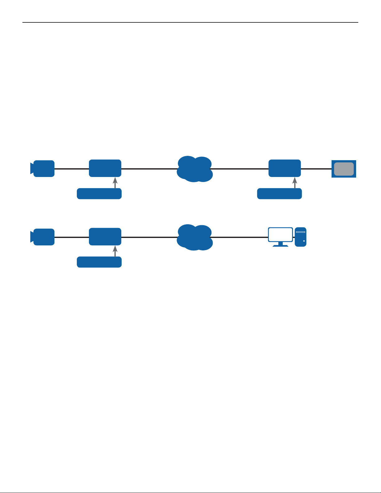
CCTV Analog
camera with PTZ
CCTV Analog
camera with PTZ
CNVETX1
Encoder
PoE or +12 VDC PoE or +12 VDC
CNVETX1
Encoder
PoE or +12 VDC
Figure 1: CNVETX1 System Typical Applications
Ethernet
Network
Ethernet
Network
Computer / Workstation
CNVETX1
Decoder
Monitor
with Internet Browser
Software
Figure 1 shows two scenarios where the CNVETX1 is connected directly to an analog camera
source and the network.
TECH SUPPORT: 1.888.678.9427
INS_CNVETX1_REV– 06/10/13 PAGE 9
Page 10

INSTALLATION AND OPERATION MANUAL CNVETX1
Software Features
» Video and audio streaming over the IP network
» Analog video input and video output
» Serial Ports for controlling PTZ cameras
» TTL alarm inputs and relay output for controlling additional sensors
» Fast Ethernet for video streaming and board control
» Industrial-grade PoE operation w/Camera Output Power
» Optional internal storage for event-driven or continuous local audio / video recording
» UDP, HTTP, TCP/IP, RTP/RTSP, SNMP, SNTP, Telnet, DHCP
» H.264, MPEG-4, and MJPEG up to D1, MPEG-2 up to 4CIF
» Intuitive Web GUI for easy configuration and setup
» Optional Video Analytics with On-Board Rule Management
Resolutions
Image size NTSC PAL
D1 720×480 pixels 720×576 pixels
4CIF 704×480 pixels 704×576 pixels
CIF 352×240 pixels 352×288 pixels
QCIF 176×112 pixels 176×144 pixel s
TECH SUPPORT: 1.888.678.9427
INS_CNVETX1_REV– 06/10/13 PAGE 10
Page 11

INSTALLATION AND OPERATION MANUAL CNVETX1
Performance (Encoder Operation Mode)
Frame Rates – Without Analytics or Local Recording
Triple Streaming:
» H.264: D1@30fps + CIF@7.5fps + QCIF@7.5fps
» MPEG-4: [D1 + CIF + QCIF]@30fps
» MJPEG: D1@30fps + CIF@7.5fps + QCIF@7.5fps
Dual streaming:
» H.264 D1@30fps + CIF [H.264@7.5fps or MPEG-4@15fps or MPEG-2@7.5fps or MJPEG@30fps]
» MPEG-4 D1@30fps + CIF@30fps[H.264 or MPEG-4 or MPEG-2 or MJPEG]
» MPEG-2 4CIF@30fps + CIF@7.5fps[H.264 or MPEG-4 or MPEG-2 or MJPEG]
» MJPEG: D1@30fps + CIF [H.264@30fps or MPEG-4@15fps or MPEG-2@7.5fps or MJPEG@10fps]
Frame Rates – With Local Recording (Internal MicroSD Card)
Dual streaming:
» Live H.264 D1@30fps + Recording H.264 CIF@15fps
» Live MPEG-4 D1@30fps + Recording H.264 CIF@15fps
» Live MPEG-2 D1@30fps + Recording H.264 CIF@15fps
» Live MJPEG D1@30fps + Recording H.264 CIF@15fps
Frame Rates – With Analytics
Dual streaming:
» H.264 D1@15fps + MJPEG CIF@30fps
» MPEG-4 [D1@15fps + CIF@30fps]
» MPEG-4 D1@15fps + MJPEG CIF@30fps
» MJPEG [D1@15fps + CIF@30fps]
» MJPEG D1@15fps + CIF@30fps[H.264 or MPEG-4]
Single streaming:
» H.264: D1@15fps or CIF@30fps
» MPEG-4: D1@15fps or CIF@30fps
» MPEG-2: 4CIF@7.5fps or CIF@15fps
» MJPEG: D1@15fps or CIF@30fps
TECH SUPPORT: 1.888.678.9427
INS_CNVETX1_REV– 06/10/13 PAGE 11
Page 12
INSTALLATION AND OPERATION MANUAL CNVETX1
Hardware Overview
Hardware Features
The ComNet IVS web server is designed to run on ComNet’s CNVETX1 unit.
The following is a specific description of the unit and its unique features.
The CNVETX1 unit contains one TI DM6446 DSP acting as an independent, standalone unit with
its own IP address, and network node.
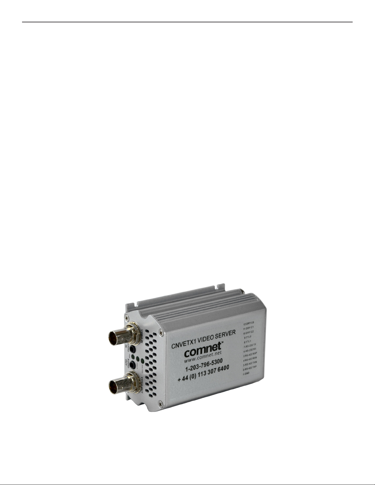
The CNVETX1 has the following physical connections:
» 1 composite BNC 75Ω connector for analog camera input
» 1 composite BNC 75Ω connector for analog camera output
» 1 RS232 serial port and 1 RS422/485 via Terminal Block
» 2 alarm inputs and 1 relay output via terminal block
» 1 Audio Mono Line/Mic input, 1 line output via 3.5 mm audio jack
» Optional factory-installed internal MicroSD Storage Card (up to 64 GB)
» Power source: 12V DC power input jack or PoE
» 12V DC power output micro-header for external camera
» 1 RJ45 10/100 Ethernet network connector
» 2 Solid State relay outputs on micro-header
» 1 USB port (Unused, reserved for future implemintation)
TECH SUPPORT: 1.888.678.9427
Figure 2: The CNVETX1 Unit
INS_CNVETX1_REV– 06/10/13 PAGE 12
Page 13
INSTALLATION AND OPERATION MANUAL CNVETX1
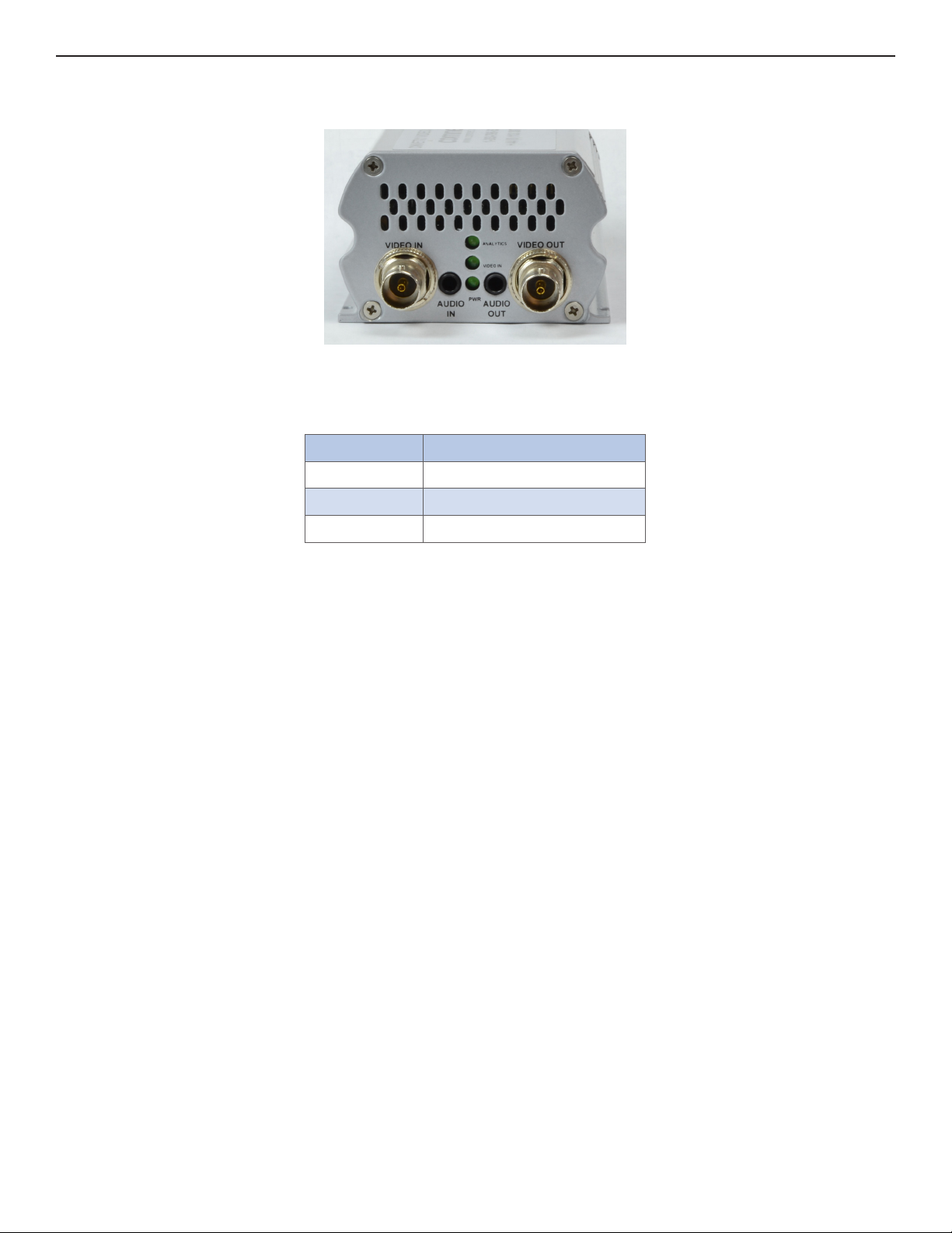
Front Panel
Figure 3: CNVETX1 Chassis Front Panel
Indicators: The three indicating LEDs on the front panel display status information.
Label Description
ANALYTICS Analytics Engine On
VIDEO IN Video Input Capturing
PWR Power (DSP Running)
Video Input: The CNVETX1 provides one analog video input. The video is connected via a 75Ω
coax cable to the BNC input connector on the front panel.
Audio Input: The CNVETX1 receives one mono input on a 3.5mm connector on the front panel.
Audio Output: The CNVETX1 transmits one mono line channel on a 3.5mm connector on the front
panel.
Video Output: The CNVETX1 provides one analog video output. The video is connected via a 75Ω
coax cable to the BNC output connector on the front panel.
TECH SUPPORT: 1.888.678.9427
INS_CNVETX1_REV– 06/10/13 PAGE 13
Page 14
INSTALLATION AND OPERATION MANUAL CNVETX1
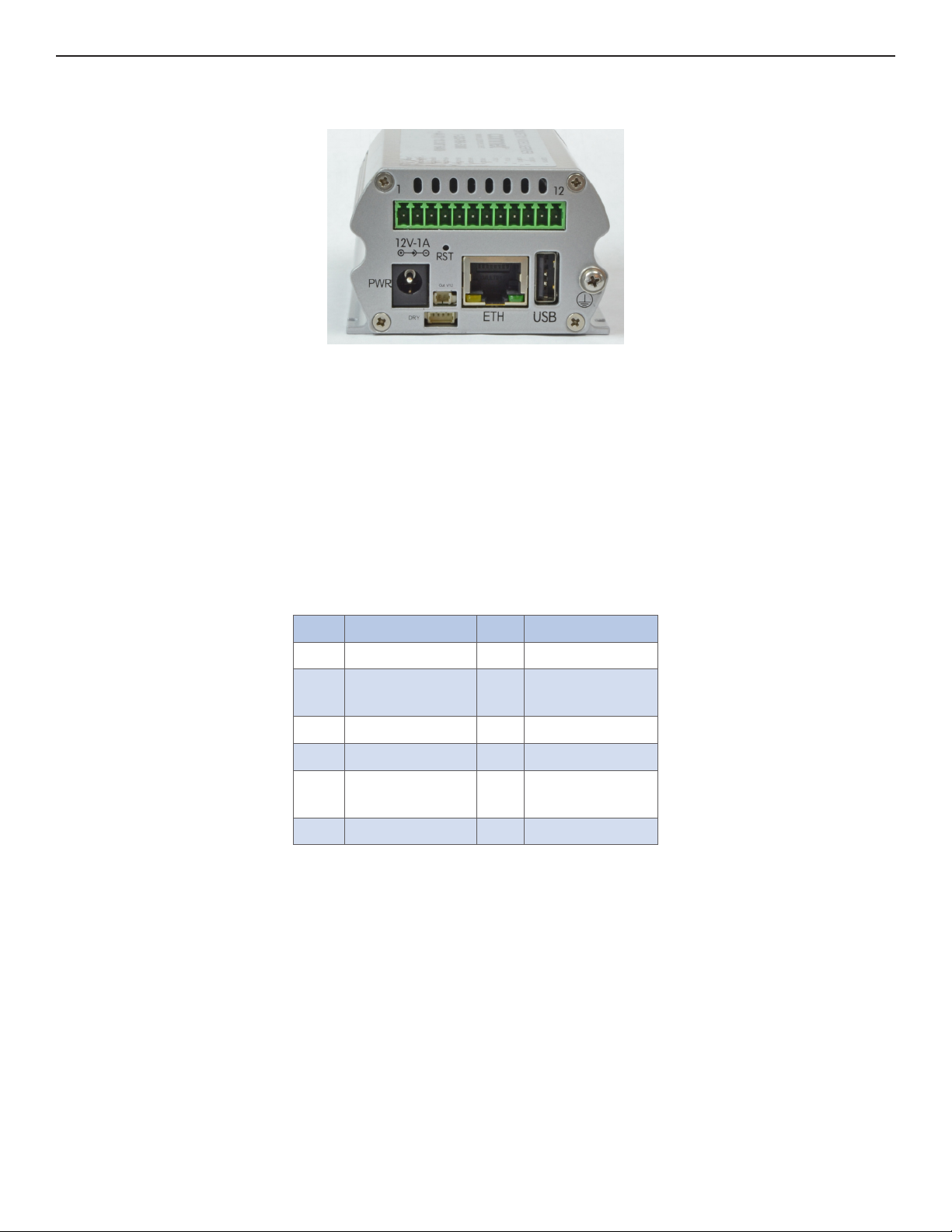
Rear Panel
Figure 4: CNVETX1 Chassis Rear Panel
12-pin I/O Terminal Connector: The CNVETX1 unit provides one relay contact comprised of the
Common Contact, the Normally Closed Contact, and the Normally Open Contact. The current
through the contacts should not exceed 1 Amp @ 30 VDC load. The CNVETX1 also provides two
TTL alarm inputs. The alarm inputs are designed as a digital logic input (-0.3V to 0.6V logic 0, 1.2V
to 5V logic 1), and are pulled up by default. One RS232 port and one RS422/485 port are also
provided.
Pin-out information for the 12-pin terminal block is provided below:
Table 3: Terminal Block Connector Pinout
Pin Description Pin Description
1 GND 7 RS232 TX
2 RS422/485 TX
+
3 RS422/485 TX – 9 TTL 0
4 RS422/485 RX – 10 Relay COM
5 RS422/485 RX +11 Relay NC
6 RS232 RX 12 Relay NO
8 TTL 1
USB Port: The CNVETX1 provides one USB 2.0 port (port has no function and is reserved
for future use).
Ethernet port: The CNVETX1 connects to the network using a standard Ethernet cable on the
back panel.
DC Power Input: Connection to the external 12V DC power supply on the back panel.
Power over Etherne t (PoE): The CNVETX1 supports a PoE operation mode. When connected to a
PoE switch, the voltage is provided from the RJ45 connector, and the 12V DC
power input is not used.
DC Power Output: Connection to an external camera (5W Max.) on the back panel.
Solid-State Relay Outputs: Connection to 2 Solid-State relays on the back panel.
TECH SUPPORT: 1.888.678.9427
INS_CNVETX1_REV– 06/10/13 PAGE 14
Page 15
INSTALLATION AND OPERATION MANUAL CNVETX1
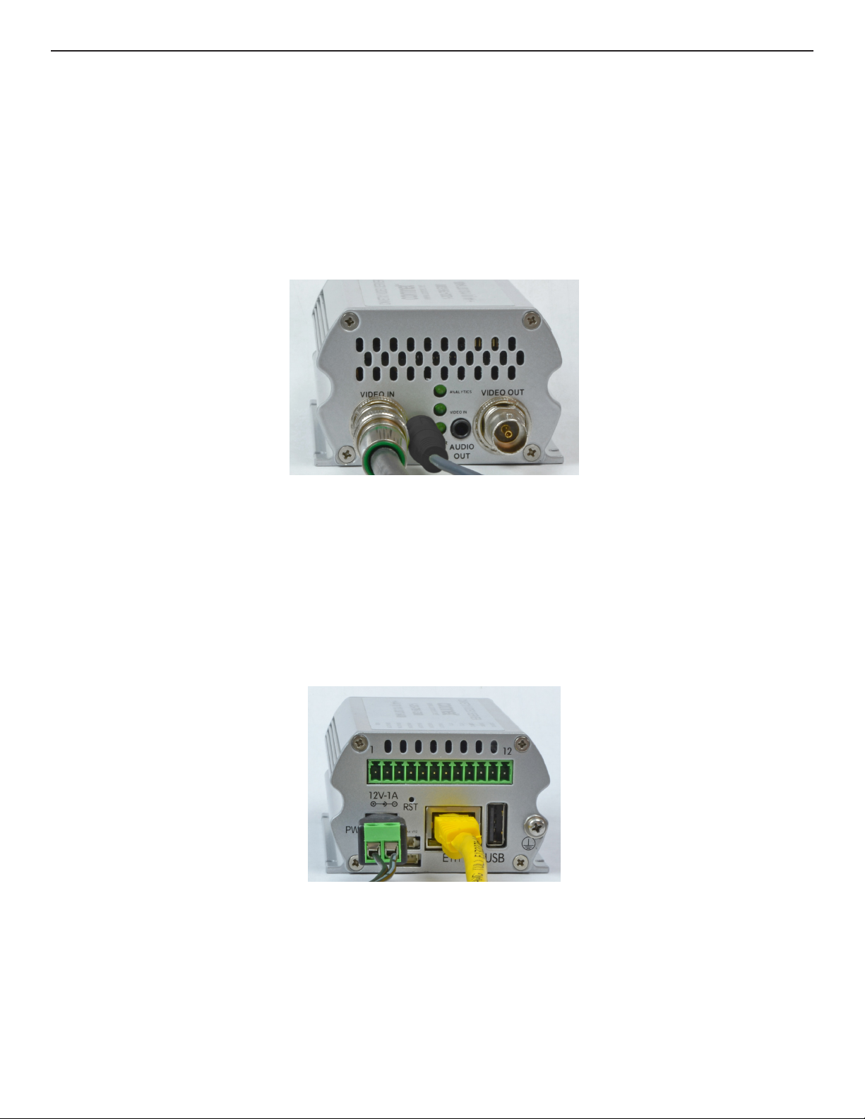
Connecting the Cables
For viewing video, the video cable, Ethernet cable and power cable must be connected. Figure 5
below shows the front panel of the CNVETX1 configured as an Encoder with the BNC video input
cable and the audio input cable. In Decoder operation, the BNC video output and audio output
shall be used.
1. Connect the CNVETX1 video input using a standard 75Ω coaxial video cable.
2. Connect the audio input using standard 3.5 mm audio cable.
Figure 5: CNVETX1 Front Panel Connectors
Figure 6 and Figure 7 show the rear panel of the CNVETX1 with the RJ45 Ethernet connector,
power connector, terminal block mating connector for the alarms and relays, and USB connector.
3. Connect the CNVETX1 unit to the network using a standard network cable.
4. Connect the power using connector to the external DC power supply. If a PoE switch is used,
the network cable supplies the power to the unit.
5. Connect the alarms and TTL inputs via the terminal connector.
Figure 6: CNVETX1 Rear Panel Connectors
TECH SUPPORT: 1.888.678.9427
INS_CNVETX1_REV– 06/10/13 PAGE 15
Page 16
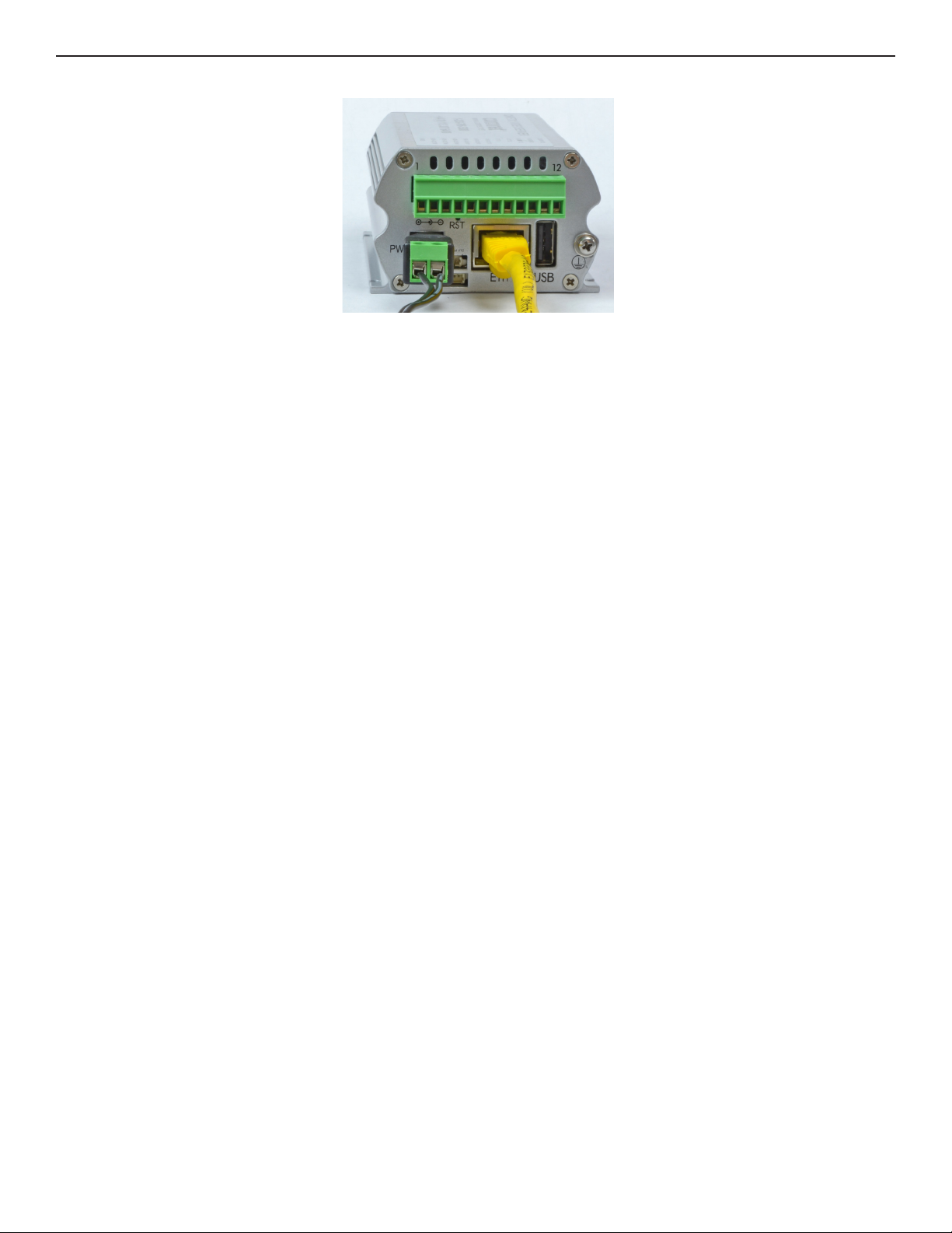
INSTALLATION AND OPERATION MANUAL CNVETX1
Figure 7: CNVETX1 Rear Panel Connectors with Terminal Block
Within a few seconds the front panel power LED 3 should light up, indicating that the unit is
functional and ready for network connections.
TECH SUPPORT: 1.888.678.9427
INS_CNVETX1_REV– 06/10/13 PAGE 16
Page 17
INSTALLATION AND OPERATION MANUAL CNVETX1
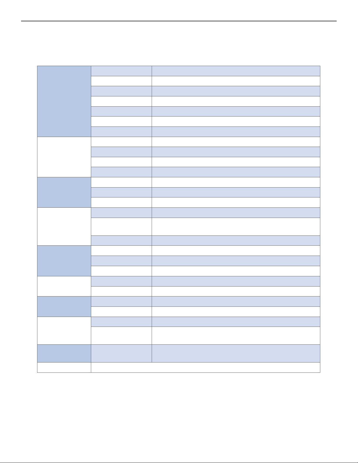
CNVETX1 Technical Specifications
Table 4: CNVETX1 Technical Specifications
Video In One Composite 1 Vpp 75Ω NTSC / PAL
Video Out One Composite 1 Vpp 75Ω NTSC / PAL
Resolutions D1 down to QCIF programmable
Video
Audio
Network
Alarms &
Contact
Closures
Serial Port
Compression H.264, MPEG-4, MPEG-2, MJEPG
Frame Rate 1-30 fps programmable
Bit Rates Configurable 32 Kbps to 20 Mbps
Connector BNC Type
Audio In Single Mono (Encoder)
Audio Out Single Mono (Decoder)
Compression G.711
Connector 3.5mm Audio Jack
Interface 10/100 Ethernet
Protocols A R P, H T T P, I G M P, R T P, R T S P, S N M P, U D P, TC P/ I P
Connector RJ-45 Connector
Input 2 TTL (- 0.3V to + 0.6V logic 0, + 1.2V to + 5V logic 1)
Output 1 SPDT Type relay (up to 1A @ 30 VDC Load)
2 Solid-State Relays (Micro-header connector)
Connector 12 Position Terminal Block (See table 3 above)
Interface RS232, RS422/485 serial ports
Connector 12 Position Terminal Block
System
Power
Environment
Regulation
Compliance
Warranty Lifetime warranty
TECH SUPPORT: 1.888.678.9427
PTZ Support Yes
Internal Storage Optional MicroSD Storage Flash, Up to 32GByte
LEDs 3 General Purpose LEDs (Power, Video, and Analytics)
Supply Voltage 6–13V DC or Power over Ethernet (PoE)
Connector DC Barrel Plug or RJ-45 connector
Form Factor 88.5 mm × 66.2 mm × 42.6 mm
Operating
-40º C to + 75º C
Temperature
Certification FCC, CE EMC and Safety RoSH
INS_CNVETX1_REV– 06/10/13 PAGE 17
Page 18

INSTALLATION AND OPERATION MANUAL CNVETX1
Getting Started
System Requirements
» Computer running Windows OS or Mac OS (for web browsing only)
» Network Access
» Internet Web browser Microsoft Internet Explorer (version 6.0 or later), or
Mozilla Firefox, or Google Chrome, or Apple Safari.
» Java Software: Download Version 6 Update 7 or later from:
http://www.java.com/en/download/index.jsp
Installation
Access your ComNet unit via its Web interface.
Web Interface
The ComNet IVS web server can be configured using the ComNet Web interface. To access the
Web configuration open a web browser and enter the unit’s IP address in the address bar. For
example, enter the following IP address: ht tp://192 .168.10.1
Note: You can leave the IP Address at the factory installed address of 192.168.10.1, or change to
an address of your choice. For instructions on changing the IP Address see Changing the IP
Address.
TECH SUPPORT: 1.888.678.9427
INS_CNVETX1_REV– 06/10/13 PAGE 18
Page 19
INSTALLATION AND OPERATION MANUAL CNVETX1
General
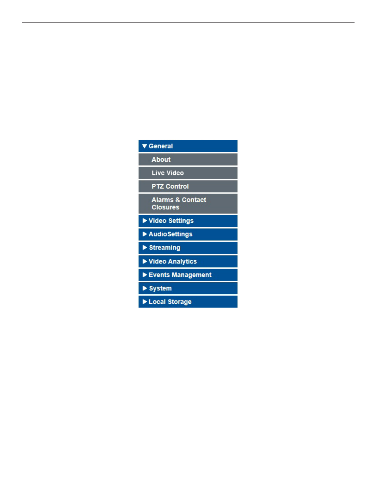
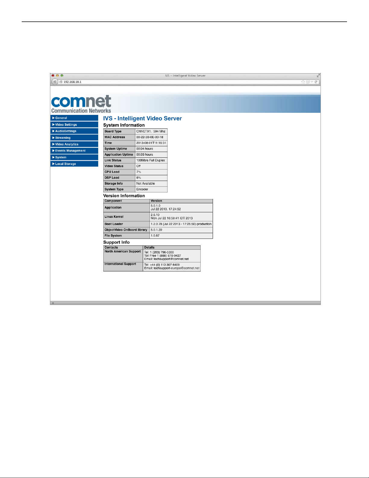
When the Web page is first entered, the About page sub menu of the General menu is displayed.
The About page displays system information such as the board name, MAC address, current date,
system and application uptime, CPU and DSP load, and storage memory information, and version
information of various software components.
The left pane contains a menu listing available options. When a menu item is selected its submenus are displayed (some sub-menus contain an additional selection of options). The right pane
contains the work area for the currently selected option.
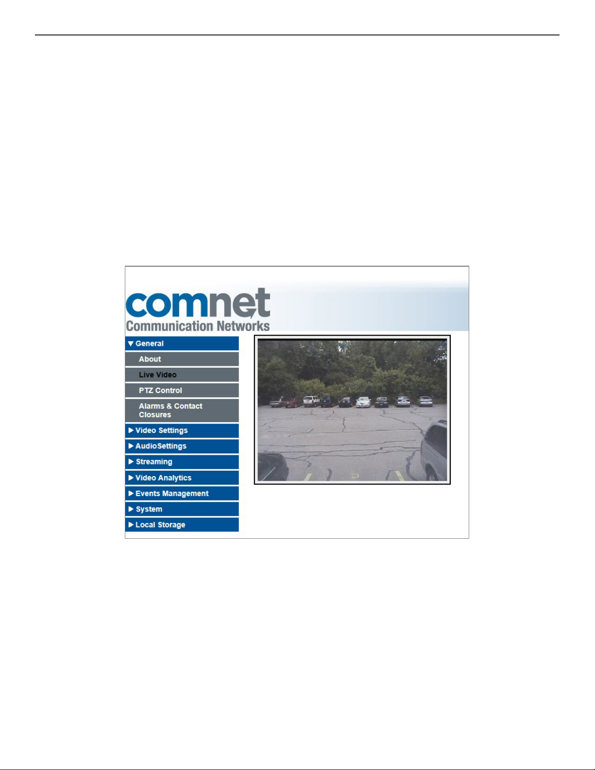
Figure 8 shows sub levels revealed when General is selected in the left pane.
TECH SUPPORT: 1.888.678.9427
Figure 8: General Sub Menus
INS_CNVETX1_REV– 06/10/13 PAGE 19
Page 20
INSTALLATION AND OPERATION MANUAL CNVETX1
About
The right pane displaying the About page appears in the browser window as shown in figure 9
(some of the system and version information may vary):
Figure 9: The About Page
Table 5 and 6 details the menus and sub-menus of the Web interface and their functions.
TECH SUPPORT: 1.888.678.9427
INS_CNVETX1_REV– 06/10/13 PAGE 20
Page 21
INSTALLATION AND OPERATION MANUAL CNVETX1
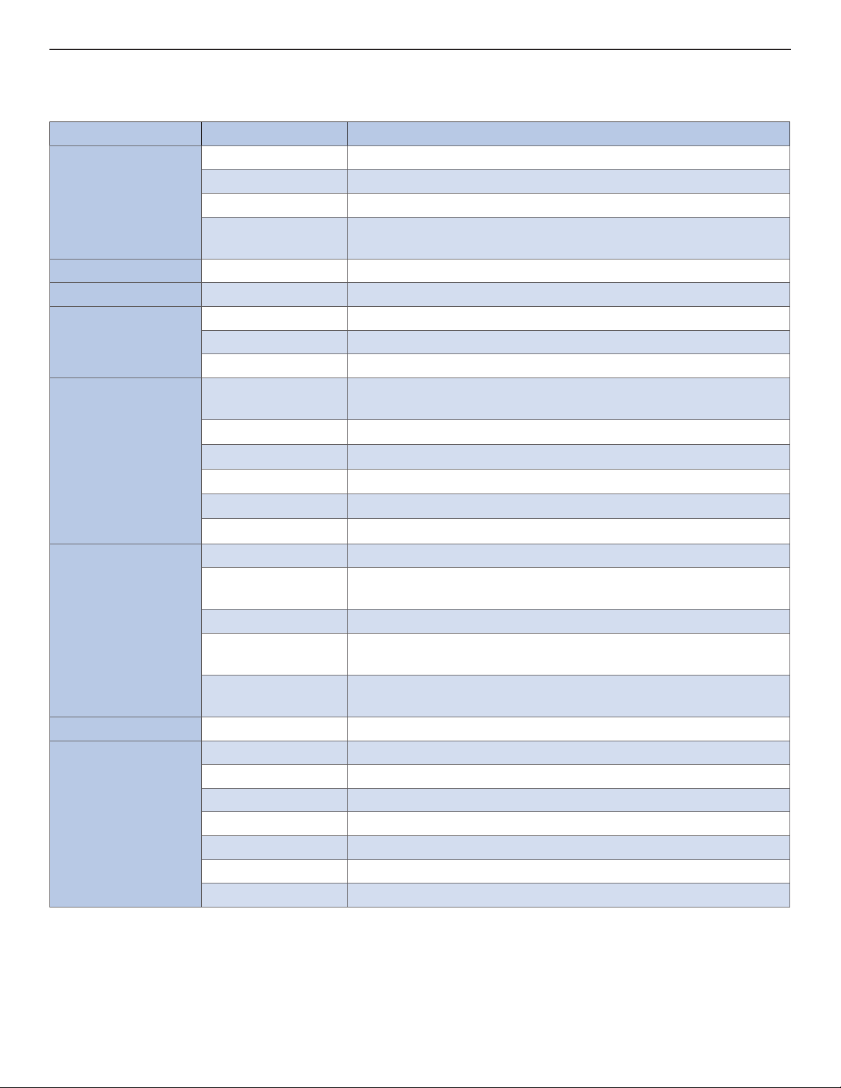
Table 5: Menu Options for Encoder Operation Mode
Encoder Option Menu Suboption Description
General About Displays general information about the application
Live Video Displays live video feed from the connected video source
PTZ Control Allows controlling of a Pan Tilt Zoom (PTZ) camera
Alarms & Contact
Closures
Video Settings Analog Video Enables setting analog video settings
Audio Settings Analog Audio Enables setting analog audio settings
Streaming General Enables setting general streaming parameters
Auto Start Enables multicast Auto Start and configure parameters
Running Streams Displays running streams
Video Encoding
Parameters
OSD
MPEG-4
MPEG-2
H.264
MJPEG
Video Analytics Software Activation Enables local key activation
General Enables setting video overlay configuration, resetting analytics
Rule Management Enables setting up rules
Enables setting (1 or 0) Relay Output, reading input status
Video encoding general parameters
Enables On-Screen-Display (OSD)
Enables setting MPEG-4
Enables setting MPEG-2
Enables setting H.264
Enables setting MJPEG
configuration
OnBoard
Configuration
Response
Management
Event Management HTTP Post Settings Enables setting HTTP server for receiving events
System Serial Port Settings Enables setting RS232 and RS422/485 terminal settings
Network Settings Enables setting network settings (Host name, IP Address, etc.)
Change Password Enables changing your password
Clock Setup Enables setting the real time clock
SNMP Settings Enables SNMP enterprise traps and thresholds
Operation Settings Enables switching between Encoder / Decoder operation modes
Firmware Upgrade Enables updating the firmware
TECH SUPPORT: 1.888.678.9427
Enables configuring the views
Enables event responses management for single or multiple
sources
INS_CNVETX1_REV– 06/10/13 PAGE 21
Page 22

INSTALLATION AND OPERATION MANUAL CNVETX1
System
Administration
Reset Resets the unit (Hardware reset may take up to 60 sec.)
Local Storage Recording Settings Enables continuos local recordings of Video and/or Audio
Reset User
Password
Change sysadmin
Password
Factory Defaults
Change Web
Interface Language
Media Files Displays local storage clips (MKV format) – Allows HTTP
SD Maintenance Sets the retention percentage (cyclic recording) and allows
Resets user password
Changing system password
Returns to factory defaults
Changing Web Language
download / delete
erasing ALL MicroSD
TECH SUPPORT: 1.888.678.9427
INS_CNVETX1_REV– 06/10/13 PAGE 22
Page 23

INSTALLATION AND OPERATION MANUAL CNVETX1
Table 6: Menu Options for Decoder Operation Mode
Decoder Options Menu Suboption Description
General About Displays general information about the application
Live Video Displays live video feed
PTZ Control Allows controlling of a Pan Tilt Zoom (PTZ) camera
Alarms & Contact
Enables setting (1 or 0) Relay Output, reading input status
Closures
Video Settings Decoder Profiles Defines up to 16 decoding profiles settings
Display
Selects the decoding profile to be used
Configuration
Video Analytics Response
Management
Enables event responses management for single or multiple
sources
Event Management HTTP Post Settings Enables setting HTTP server for receiving events
System Serial Port Settings Enables setting RS232 and RS422/485 terminal settings
Network Settings Enables setting network settings (Host name, IP Address, etc.)
Change Password Enables changing your password
Clock Setup Enables setting the real time clock
SNMP Settings Enables SNMP enterprise traps and thresholds
Operation Settings Enables switching between Encoder / Decoder operation
modes
Firmware Upgrade Enables updating the firmware
System
Administration
Reset User
Password
Resets user password
Change sysadmin
Changing system password
Password
Factory Defaults Returns to factory defaults
Change Web
Changing Web Language
Interface Language
Reset Resets the unit (Hardware reset may take up to 60 sec.)
TECH SUPPORT: 1.888.678.9427
INS_CNVETX1_REV– 06/10/13 PAGE 23
Page 24
INSTALLATION AND OPERATION MANUAL CNVETX1
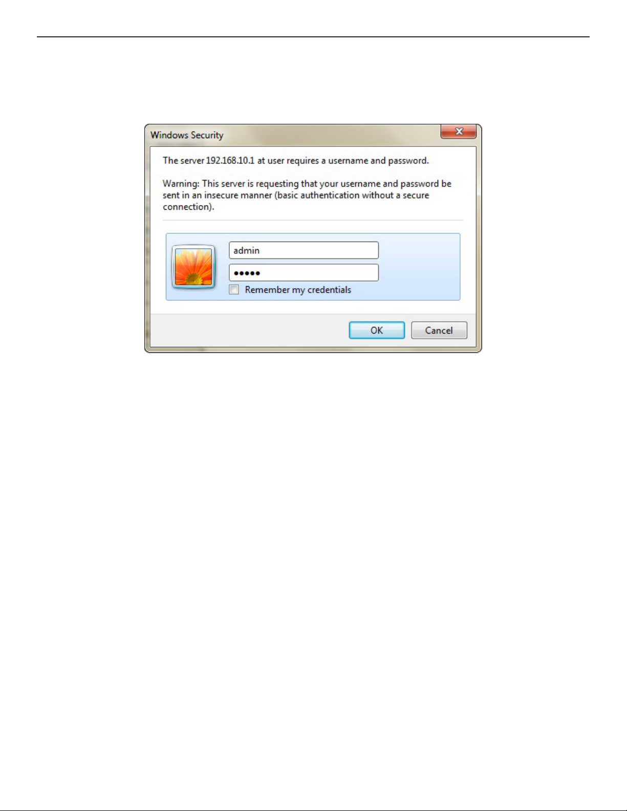
Password Protected Options
Most menu options require a user/password combination to access them. When an option is
password-protected the Authentication Required window appears.
Figure 10: Enter Password
To access password-protected options:
1. In the Authentication Required window, in the User Name text-box type your user name, and in
the Password text-box type your password.
Note: By default, the username is admin, and the default password is admin.
2. Select OK.
Note: For system administration level password see System Administration.
TECH SUPPORT: 1.888.678.9427
INS_CNVETX1_REV– 06/10/13 PAGE 24
Page 25
INSTALLATION AND OPERATION MANUAL CNVETX1
Monitoring Live Video
The Live Video screen enables viewing a live video feed from the camera connected to the video
server through the Live Video pane (Java plug-in is required). In addition, operating as an Encoder,
it is possible to monitor live video streaming using a media player such as QuickTime or VLC.
Live Video
The Live Video displays the video image of the input video source – Analog input for Encoder or
digital input for Decoder. The video source is displayed on the Live View page at CIF resolution
at 1/3 of the full frame rate. Thus, if you are running in NTSC video mode, the Live View page
displays the data at 10 frames per second.
Figure 11 below displays an example of a fixed outdoor camera connected to a CNVETX1 on the
network.
Figure 11: Live Video Page
To display live video:
» In the left pane select the General menu, and from the sub-menus select Live Video.
» The right-pane displays the live video.
TECH SUPPORT: 1.888.678.9427
INS_CNVETX1_REV– 06/10/13 PAGE 25
Page 26
INSTALLATION AND OPERATION MANUAL CNVETX1
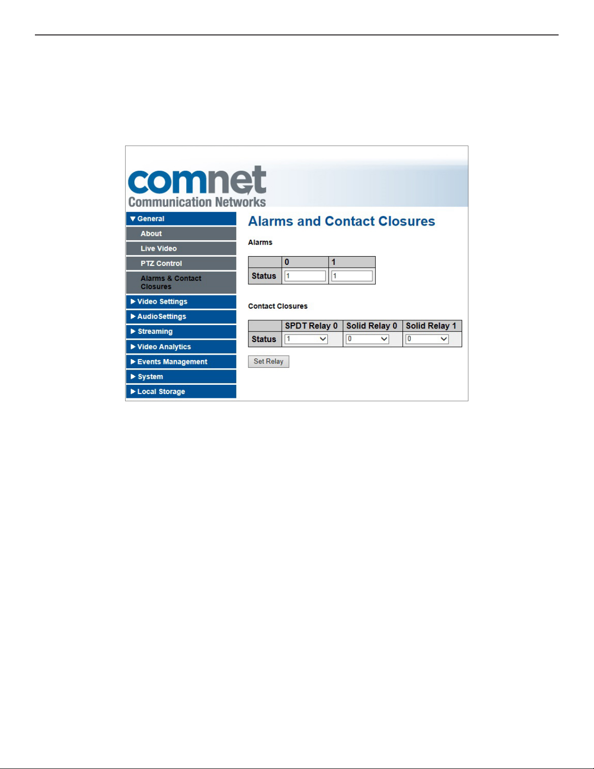
Alarms and Contact Closures
The Alarms & Contact Closures pane enables you to view the status of the TTL alarm inputs and
set the contact closures outputs. There are two alarm inputs, one dry contact relay output, and
two solid-state relay outputs. The inputs are status bits and are read only. The relays can be set to
Normally Open (1) or Normally Closed (0).
Figure 12: Alarms and Contact Closures Page
TECH SUPPORT: 1.888.678.9427
INS_CNVETX1_REV– 06/10/13 PAGE 26
Page 27
INSTALLATION AND OPERATION MANUAL CNVETX1
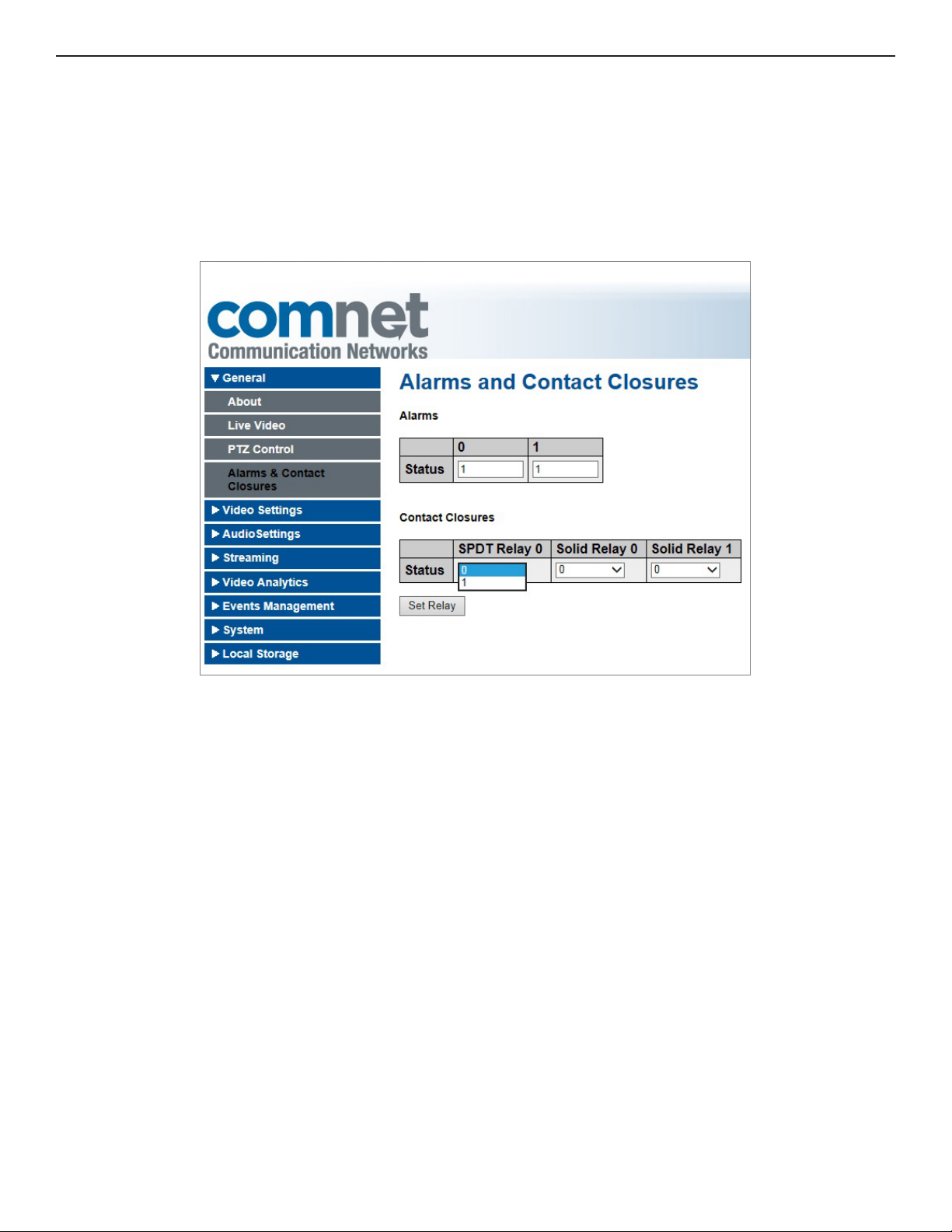
To set contact closure output:
1. Select the General menu in the left pane, and from the sub-menus select Alarms & Contact
Closures.
2. Select 0 or 1 from the drop down menu in the right pane within the Contact Closures section.
3. Select Set Relay.
Figure 13: Setting the Contact Closures
TECH SUPPORT: 1.888.678.9427
INS_CNVETX1_REV– 06/10/13 PAGE 27
Page 28
INSTALLATION AND OPERATION MANUAL CNVETX1
Controlling a Pan Tilt Zoom (PTZ) Camera
The Web interface enables controlling the Pan and Tilt movement of a PTZ camera as well as
the zoom, focus, and iris operations. When operating as an Encoder, the analog video input may
be connected to a PTZ camera and configured from a choice of seven camera protocols. The
following procedures outline how to configure the PTZ camera and how to control its movement.
Configuring a PTZ Camera
The PTZ cameras are configured in the PTZ Control Configuration interface.
To configure the PTZ camera:
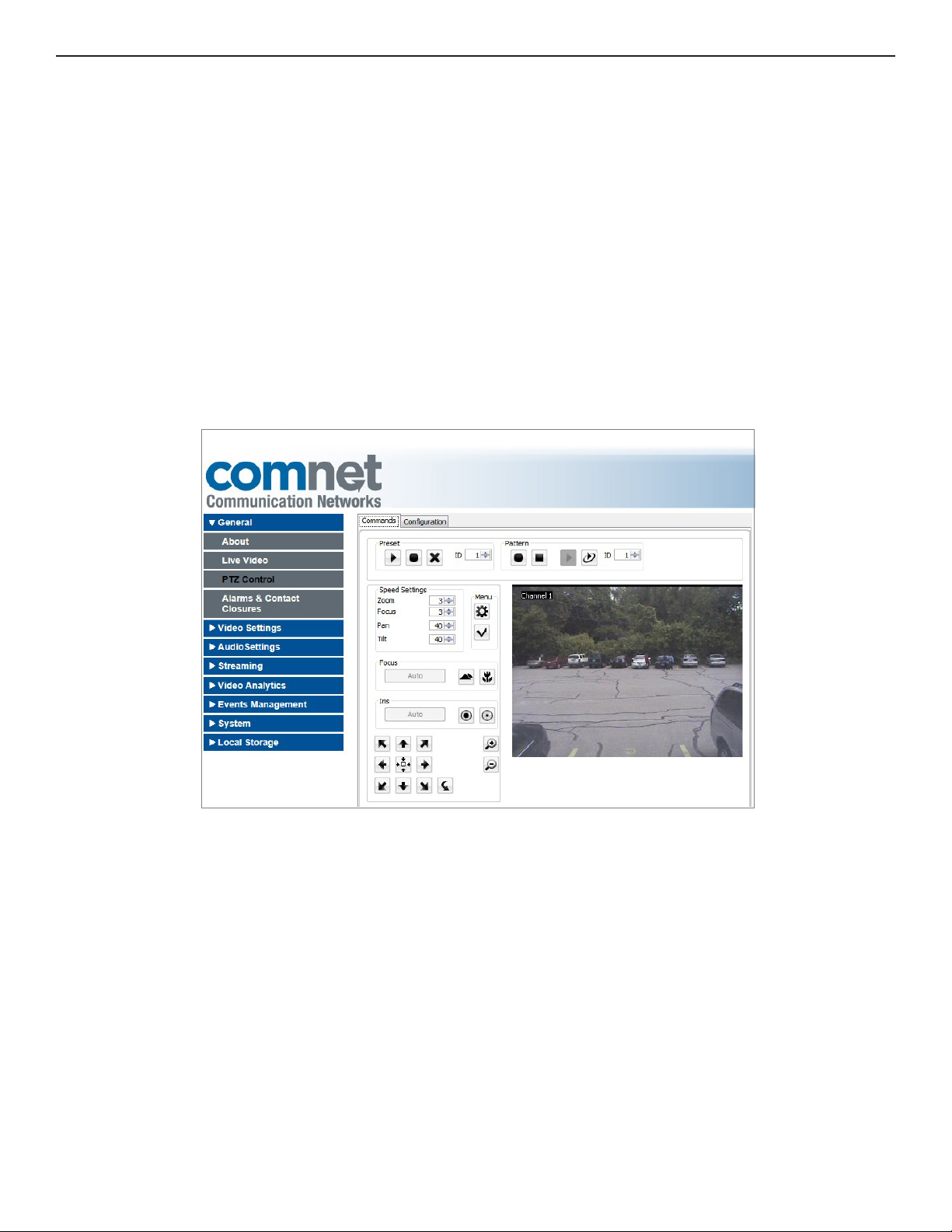
1. Select the General menu in the left pane, then in the left pane, select PTZ Control.
The right pane displays the PTZ commands work area (Java plug-in is required).
Figure 14: PTZ Commands Page
2. Select the Configuration tab to display the Configurations page.
TECH SUPPORT: 1.888.678.9427
INS_CNVETX1_REV– 06/10/13 PAGE 28
Page 29
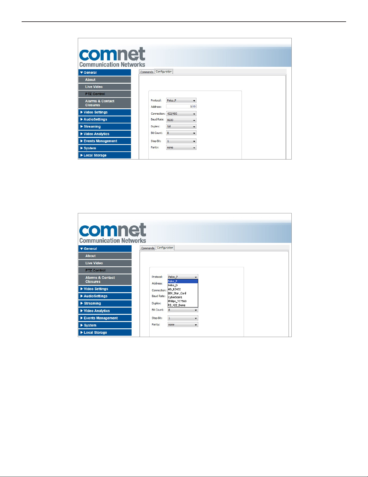
INSTALLATION AND OPERATION MANUAL CNVETX1
Figure 15: PTZ Configuration Page
3. Select a camera protocol
4. From the Protocol drop-down list. The choices of protocols are Pelco_P, Pelco_D, AD_RS422,
BBV_Star_Card, CyberScan1, Phillips_TC7560, RS_422_Dome.
Figure 16: Select Camera Protocol
5. Select the address which is the ID of the selected camera from the Address drop-down list.
The ranges vary for each protocol.
Refer to Supported PTZ Protocols Parameter Range.
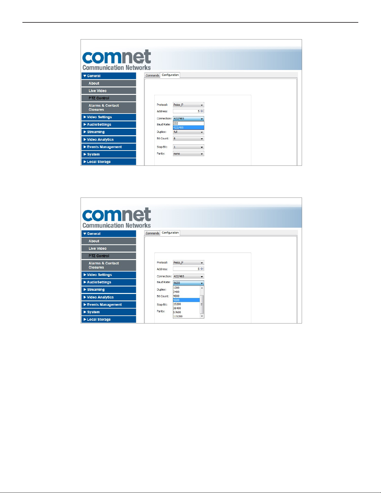
6. Choose 232 for RS-232, 422/485 for RS422/485 from the Connection drop-down list.
7. The RS232 and RS422/485 are separate physical ports and have separate connectors.
TECH SUPPORT: 1.888.678.9427
INS_CNVETX1_REV– 06/10/13 PAGE 29
Page 30
INSTALLATION AND OPERATION MANUAL CNVETX1
Figure 17: Connection Type
8. Select the baud rate from the Baud Rate drop-down list.
Figure 18: Select the Baud Rate
9. Select full for full duplex mode or half for half duplex mode from the Duplex drop-down list.
TECH SUPPORT: 1.888.678.9427
INS_CNVETX1_REV– 06/10/13 PAGE 30
Page 31

INSTALLATION AND OPERATION MANUAL CNVETX1
Figure 19: Select Full or Half Duplex Mode
10. Select 7 or 8 bits from the Bit Count drop-down list.
Figure 20: Select Bit Count
11. Select 1 or 2 stop bits from the Stop Bit drop-down list.
TECH SUPPORT: 1.888.678.9427
INS_CNVETX1_REV– 06/10/13 PAGE 31
Page 32

INSTALLATION AND OPERATION MANUAL CNVETX1
Figure 21: Select Stop Bits
12. Select none, odd, or even parity from the Parity drop-down list.
Figure 22: Select Parity
13. Select Apply to save the settings
14. Select the Commands tab to return to the PTZ Control command display.
TECH SUPPORT: 1.888.678.9427
INS_CNVETX1_REV– 06/10/13 PAGE 32
Page 33

INSTALLATION AND OPERATION MANUAL CNVETX1
Controlling the Pan and Tilt Movement of a PTZ Camera
Controlling the pan and tilt movement of a PTZ Camera is done by using the keyboard arrow keys
or by selecting the appropriate symbol on the graphical user interface. When a key is pressed,
the camera moves in the direction of the pressed key. The possible directions are tiltUp, tiltDown,
panLeft, panRight, PTLeftUp, PTRightUp, PTLeftDown, and PTRightDown.
Note: During normal keyboard use, the NumLock key is not activated, which means that the
direction arrows on the numeric keypad keys are operational.
Figure 23: PTZ Commands
To pan and tilt a PTZ camera:
1. Use the directional arrow keys on the numeric keypad or select the mouse on the graphical
user interface to control the camera the pan and tilt movement.
Figure 24: Arrow Keys and Symbols for Pan and Tilt Control
2. Press down an arrow key or symbol to move the camera. When you stop pressing the key the
camera stops.
3. Press down on the zeroPanPosition to automatically position the camera in the zero pan position.
4. Press down on the Flip symbol to cause the camera to flip 180 degrees from its current position.
TECH SUPPORT: 1.888.678.9427
INS_CNVETX1_REV– 06/10/13 PAGE 33
Page 34

INSTALLATION AND OPERATION MANUAL CNVETX1
Table 7: PTZ Movement Control
Key Symbol Description
8 Tilt up
2 Tilt down
4 Pan left
6 Pan right
7 Pan Tilt left up
9 Pan Tilt right up
1 Pan Tilt left down
3 Pan Tilt right down
5
Zero Position
N/A Flip 180°
TECH SUPPORT: 1.888.678.9427
INS_CNVETX1_REV– 06/10/13 PAGE 34
Page 35

INSTALLATION AND OPERATION MANUAL CNVETX1
Panning a PTZ Camera
The following figures illustrate the panning of a PTZ camera using the keypad symbols on the
Command user interface. The figures show a PTZ camera panned at 0°, 15°, and 40°. The video is
overlaid with the pan angle. The overlay originates from the camera.
Figure 25: PTZ Camera at 0°
Figure 26: PTZ Camera at 15°
TECH SUPPORT: 1.888.678.9427
INS_CNVETX1_REV– 06/10/13 PAGE 35
Page 36

INSTALLATION AND OPERATION MANUAL CNVETX1
Figure 27: PTZ Camera at 40°
Camera Movement Speed
The camera movement speed is controlled by the value set in the Speed Settings area. The Zoom,
Focus, Pan, and Tilt speeds are controlled by selecting a speed setting from the drop-down lists.
Unsupported speed parameters will be shaded out and unavailable.
To set the camera movement speed:
1. In the Speed Settings area, enter a numeric value to set the camera zoom speed.
2. In the Speed Settings area, enter a numeric value to set the camera focus speed.
3. In the Speed Settings area, enter a numeric value to set the camera pan speed.
4. In the Speed Settings area, enter a numeric value to set the camera tilt speed.
Figure 28: Speed Settings
Refer to Supported PTZ Protocols Parameter Range for the range of speed settings supported.
TECH SUPPORT: 1.888.678.9427
INS_CNVETX1_REV– 06/10/13 PAGE 36
Page 37

INSTALLATION AND OPERATION MANUAL CNVETX1
Table 8: Supported PTZ Protocols Parameter Range
Camera
Pelco_P
Pelco_D
AD-RS422
BBV_Star_Card
CyberScan1
Phillips_TC7560
RS_422_Dome
Focus
Speed
Min: 0
Max: 3
Min: 0
Max: 3
Min: 0
Max: 3
Min: 0
Max: 3
Min: 0
Max: 3
Min: 0
Max: 3
Min: 0
Max: 3
Zoom
Speed
Min: 0
Max: 3
Min: 0
Max: 3
Min: 0
Max: 3
Min: 0
Max: 3
Min: 0
Max: 3
Min: 0
Max: 3
Min: 0
Max: 3
Pan
Speed
Min: 0
Max: 64
Min: 0
Max: 64
Min: 1
Max: 100
Min: 1
Max: 1
Min: 1
Max: 1
Min: 1
Max: 1
Min: 1
Max: 1
Zoom, Focus and Iris Control of a PTZ Camera
Tilt
Speed
Min: 0
Max: 63
Min: 0
Max: 63
Min: 1
Max: 100
Min: 1
Max: 1
Min: 1
Max: 1
Min: 1
Max: 1
Min: 1
Max: 1
Preset
ID
Min: 1
Max: 255
Min: 1
Max: 32
Min: 1
Max: 96
Min: 1
Max: 7
Min: 1
Max: 15
Min: 1
Max: 99
Min: 1
Max: 4
Pattern
ID
Min: 1
Max: 4
Min: 1
Max: 8
Min: 1
Max: 3
Min: 1
Max: 1
Min: 1
Max: 1
Min: 1
Max: 1
Min: 1
Max: 3
Address
Range
Min: 1
Max: 32
Min: 1
Max: 255
Min: 1
Max: 99
Min: 1
Max: 96
Min: 1
Max: 255
Min: 1
Max: 1000
Min: 1
Max: 99
Zooming in and out, focusing the PTZ camera, and Iris control is performed using the relevant
symbols on the graphical user interface page of the PTZ control menu.
Table 9: Zoom Focus and Iris Symbols
Symbol Description
Zoom Tele (In)
Zoom Wide (Out)
Focus Far
Focus Near
Open Iris
Close Iris
To control the zoom, focus, and iris of a PTZ camera:
1. In the Zoom area press the Zoom tele symbol to zoom in.
2. In the Zoom area press the Zoom wide symbol to zoom out.
TECH SUPPORT: 1.888.678.9427
INS_CNVETX1_REV– 06/10/13 PAGE 37
Page 38

INSTALLATION AND OPERATION MANUAL CNVETX1
Figure 29: Zoom Area
3. In the Focus area press the Focus far or Focus near symbols to focus the camera. On some
cameras there is an auto focus command as well.
Figure 30: Focus Area
4. In the Iris area press the left icon to open the camera iris.
5. In the Iris area press the right icon to close the iris. On some cameras there is an auto iris
command as well.
Figure 31: Iris Area
TECH SUPPORT: 1.888.678.9427
INS_CNVETX1_REV– 06/10/13 PAGE 38
Page 39

INSTALLATION AND OPERATION MANUAL CNVETX1
Zooming the Camera
The following figures illustrate the zoom capability of a PTZ camera. An overlay on the picture
gives an indication of the zoom. The overlay is a function of the camera. Some cameras have the
capability of displaying a zoom factor or a pan angle while others do not.
Figure 32: PTZ Display
Figure 33: Zooming In on Parked Car – 12.0
TECH SUPPORT: 1.888.678.9427
INS_CNVETX1_REV– 06/10/13 PAGE 39
Page 40

INSTALLATION AND OPERATION MANUAL CNVETX1
Figure 34: Zooming In on Parked Car – 30.0
TECH SUPPORT: 1.888.678.9427
INS_CNVETX1_REV– 06/10/13 PAGE 40
Page 41

INSTALLATION AND OPERATION MANUAL CNVETX1
Focusing the Camera
The following figures illustrate the focus capability of a PTZ camera. Use the focus symbols to
bring the picture into focus.
Figure 35: Out of Focus
Figure 36: In Focus
TECH SUPPORT: 1.888.678.9427
INS_CNVETX1_REV– 06/10/13 PAGE 41
Page 42

INSTALLATION AND OPERATION MANUAL CNVETX1
PTZ Camera Preset
Set and store preset locations (camera pan and tilt settings) for the cameras, and then recall them
with the ID spin box list on the graphical user interface preset area.
Figure 37: Preset Area
The number of presets allowed varies with the camera protocol selected and camera model. Refer
to Supported PTZ Protocols Parameter Range for the number of presets allowed per protocol.
describes each of the preset symbols.
Table 10: Preset Symbols
Symbol Description
GoTo preset location
Define preset
Delete preset
To define a preset:
1. Select an ID.
2. Move the camera to the desired location by using the Pan and Tilt symbols.
3. Select the Define preset symbol.
4. Move the camera to a different location.
5. Select the GoTo preset location to jump to the preset defined.
To delete a preset:
1. Select an ID
2. Select the Delete preset symbol on the graphical user interface.
TECH SUPPORT: 1.888.678.9427
INS_CNVETX1_REV– 06/10/13 PAGE 42
Page 43

INSTALLATION AND OPERATION MANUAL CNVETX1
PTZ Camera Pattern
Set and store patterns of movement (camera pan and tilt settings) for the cameras, then recall
them with the ID spin box list on the graphical user interface preset area shown below.
Figure 38: Pattern Area
The number of patterns allowed varies with the camera protocol selected and camera model.
Refer to Supported PTZ Protocols Parameter Range for the number of patterns allowed per
protocol. The symbol table below describes each of the preset symbols.
Table 11: Pattern Symbols
Symbol Description
Start define pattern
Finish define pattern
Run pattern once
Run pattern repeatedly
To define a pattern:
1. Select a camera ID.
2. Select the Start define pattern symbol on the graphical user interface.
3. Use the pan and tilt symbols to define a pattern of movement of the camera.
4. Select the finish define pattern symbol.
5. Select the Run pattern once or Run pattern repeatedly to run the defined pattern.
TECH SUPPORT: 1.888.678.9427
INS_CNVETX1_REV– 06/10/13 PAGE 43
Page 44

INSTALLATION AND OPERATION MANUAL CNVETX1
Configuring from within the Camera’s User Interface
The selected camera can be defined through a user interface overlaid on the video. The symbol
opens the textual menu of the selected camera on the screen. The On Screen Display (OSD) is
used to set many of the features of the camera. The Select Menu icon is used to select the item
that is highlighted on the OSD.
Figure 39: Menu Symbols
Table 12: Menu Symbols
Symbol Description
Open textual menu screen
Select menu item
The menu that is displayed will vary according to the camera model.
Audio/Video Configuration
The Video Settings menu is used to configure the Analog Video Settings.
The Streaming menu is used to set the video encoding general parameters and configure the
video CODECs. This menu is also used to configure the general streaming parameters and to view
the active running streams.
The Audio Settings menu is used to configure the analog audio settings.
When hovering over a field, the tool tip describes the field. When hovering over a field containing
a required parameter, the allowed range of values appears.
TECH SUPPORT: 1.888.678.9427
INS_CNVETX1_REV– 06/10/13 PAGE 44
Page 45

INSTALLATION AND OPERATION MANUAL CNVETX1
Configuring Video Settings – Encoder Operation Mode
In the Video Settings menu select on Analog Video to specify the Video Standard, Brightness,
Contrast, Color, Hue, De-Interlace, and Noise Reduction. Possible video standards are PAL, and
NTSC. Each standard has a different image size and frame rate.
Figure 40: Video Standard Selection
To configure analog video settings:
1. In the left pane select the Video Settings menu, and from the sub-menu select Analog Video.
The right pane displays the Analog Video Settings area.
2. From the Video Standard drop-down list select the video standard for the camera.
3. You can set the brightness, contrast, and color to a value in the range 1 – 100.
4. You can set the hue to a value in the range -50 to +50.
5. Check the De-Interlace box to enable the De-Interlace function.
6. Check the Noise Reduction box to enable the Noise Reduction function.
7. Select the Video out display box to enable the video output operation.
8. Select Save.
TECH SUPPORT: 1.888.678.9427
INS_CNVETX1_REV– 06/10/13 PAGE 45
Page 46

INSTALLATION AND OPERATION MANUAL CNVETX1
Configuring Video Encoding Parameters
The Video Encoding General Parameters of Image Size and Frame Rate are set in this sub menu.
Image Size
Select the image size of the video stream. The image size can be adjusted between QCIF, CIF,
4CIF, and D1.
Table 13 shows the different video formats and their associated resolutions.
Table 13: Video Formats and Resolutions
Video Resolution
Format
QCIF 176 × 14 4
CIF 352 × 288 352 × 240
4CIF 704 × 576 704 × 480
D1 720 × 480 720 × 576
PAL
Video Resolution
NTSC
176 × 112
Frame Rate
The frame rates correspond to the number of frames per second. The frame rate is different when
in NTSC or in PAL.
The supported frame rates for NTSC are:
1, 1.2, 1.25, 1.5, 1.875, 2, 2.5, 3, 3.75, 5, 6, 7.5, 10, 15, 30
The supported frame rates for PAL are:
1, 1.25, 1.5625, 2.5, 3.125, 5, 6.25, 12.5, 25
To set the video encoding general parameters:
1. In the left pane select the Streaming menu, and from the sub-menus select Video and then
Encoding Parameters.
The right pane displays the Video Encoding General Parameters area.
TECH SUPPORT: 1.888.678.9427
INS_CNVETX1_REV– 06/10/13 PAGE 46
Page 47

INSTALLATION AND OPERATION MANUAL CNVETX1
Figure 41: Video Streaming General Parameters
2. From the Image Size drop-down list select the image size of the video stream. The image size
can be adjusted between QCIF, CIF, 4CIF, and D1 as shown in the figure below.
Figure 42: Adjusting the Image Size
3. From the Frame Rate drop-down list select the frame rate.
TECH SUPPORT: 1.888.678.9427
INS_CNVETX1_REV– 06/10/13 PAGE 47
Page 48

INSTALLATION AND OPERATION MANUAL CNVETX1
4. Select Save.
TECH SUPPORT: 1.888.678.9427
Figure 43: Frame Rate Settings for PAL and NTSC
INS_CNVETX1_REV– 06/10/13 PAGE 48
Page 49

INSTALLATION AND OPERATION MANUAL CNVETX1
Configuring the OSD Feature
The OSD feature allows embed a small logo, free text, date and time, into the live stream image.
Figure 44: OSD Parameters
Profile Number and Video Resolution
There are up to 3 possible profiles. Each profile is associated with one of the supported video
resolutions: 4CIF/D1, CIF, and QCIF
Logo File
Using a Java applet, a logo can be added onto the live stream.
The logo format can be JPEG or BMP. The maximum width is 256 pixels and the maximum height
is 96 pixels. The logo placement is done by entering horizontal (X) and vertical (Y) offsets in pixels.
Free Text OSD
Free text up to 32 characters can be configured.
Text font size, color, and background color are configurable. The free text placement is done by
entering horizontal (X) and vertical (Y) offsets in pixels.
TECH SUPPORT: 1.888.678.9427
INS_CNVETX1_REV– 06/10/13 PAGE 49
Page 50

INSTALLATION AND OPERATION MANUAL CNVETX1
Date & Time OSD
Date and/or time info can be configured.
The date and time format, size, color, and background color are configurable. The date and/or
time placement are done by entering horizontal (X) and vertical (Y) offsets in pixels.
Figure 45: OSD Text / Date / Time Colors
Configuring the MPEG-4 Video CODEC
You can set the MPEG-4 video CODEC settings of GOP Size, Rate Control Mode, Constant Bit rate,
Average Bit rate, Maximum Bit rate, and Q Initial.
GOP Size
In order to allow high compression rates for digital video it may be encoded into GOPs, or Groups
of Pictures, which consist of key frames (I-Frames) and delta frames (P or B Frames). The Group of
Pictures GOP Size defines the distance between consecutive I-Frames in a video stream.
Rate Control Mode
The Rate Control Mode parameter defines Rate control options for the MPEG-4 encoder. The
options are CBR, VBR, and Constant Q.
In CBR encoding the bit rate is kept constant and is useful for streaming multimedia content on
limited capacity channels.
TECH SUPPORT: 1.888.678.9427
INS_CNVETX1_REV– 06/10/13 PAGE 50
Page 51

INSTALLATION AND OPERATION MANUAL CNVETX1
VBR files vary the amount of output data per time segment. VBR allows a higher bit rate (and
therefore more storage space) to be allocated to the more complex segments of media files while
less space is allocated to less complex segments. The average of these rates can be calculated to
produce an average bit rate for the file.
The advantages of VBR are that it produces a better quality-to-space ratio compared to a CBR file
of the same size. The disadvantages are that it may take more time to encode, as the process is
more complex, and that some hardware might not be compatible with VBR files.
In Constant Q mode only Q Initial is entered. This mode is intended to keep a constant quality.
A low Q setting will generally have a high bit rate providing high quality. A high Q setting will
generally have a low bit rate with lower quality.
Each mode has its own relevant parameters. Other parameters are shaded.
Bit rate
The Bit rate parameter is the bit rate of the stream. The Bit rate can be set to a value in the range
of 50000 to 10000000. The default value is 4000000.
The rate control mode determines the required parameters:
» Average Bit rate: Average bit rate of the video stream (VBR mode only).
» Maximum Bit rate: Maximum bit rate of the video stream (VBR mode only).
» Constant Bit rate: The bit rate of the video stream (CBR mode only).
Quantization
The Q (Quantization) parameters are quality settings, where 8 is lowest quantization and highest
quality (and more bits used), and 30 is the highest quantization and lowest quality (and less bits
used).
The rate control mode determines the required parameter.
» QInitial: Quantization value used in the first encoded frame. In Constant Q mode this value
shall remain fixed for all frames.
The figures below show the CBR, VBR, and Constant Q modes of the MPEG-4 encoder.
TECH SUPPORT: 1.888.678.9427
INS_CNVETX1_REV– 06/10/13 PAGE 51
Page 52

INSTALLATION AND OPERATION MANUAL CNVETX1
Figure 46: MPEG-4 CBR Parameters
Figure 47: MPEG-4 VBR Parameters
TECH SUPPORT: 1.888.678.9427
INS_CNVETX1_REV– 06/10/13 PAGE 52
Page 53

INSTALLATION AND OPERATION MANUAL CNVETX1
Figure 48: MPEG-4 Constant Q Parameters
To set the MPEG-4 Video CODEC:
1. In the left pane select the Streaming menu, and from the sub-menus select Video and then
MPEG-4.
The right pane displays the MPEG-4 Parameters area.
2. In the GOP Size text-box Select the number of frames in a GOP (Group of Pictures) in the range
of 1–100.
3. From the Rate Control Mode drop-down list select the rate control mode for the MPEG-4
encoder. The default is CBR.
› VBR (Variable Bit Rate)
› CBR (Constant Bit Rate)
› Constant Q (Constant Quantization)
4. Enter the required bit rate parameter according to the rate control mode (between 50000 to
10000000):
› VBR:
Average Bit rate - average bit rate of the video stream. The default is 4000000
Maximum Bit rate – maximum bit rate of the video stream. The default is 5000000
› CBR: the constant bit rate of the video stream. The default is 4000000
› CONSTANT_Q: No bit rate control.
Table 5 – UTC Time Zones
TECH SUPPORT: 1.888.678.9427
INS_CNVETX1_REV– 06/10/13 PAGE 53
Page 54

INSTALLATION AND OPERATION MANUAL CNVETX1
5. Enter the required Q parameters. The range of QInitial is 8 to 30.
› CBR:
Q Initial: initial quantization value. The default is 8
› CONSTANT_Q:
Q Initial: initial quantization value. The default is 8
Configuring the MPEG-2 Video CODEC
You can set the MPEG-2 video CODEC settings of GOP Size, Rate Control Mode, Average Bit rate,
Maximum Bit rate, Bit rate and Q Initial.
GOP Size
In order to allow high compression rates for digital video it may be encoded into GOPs, or Groups
of Pictures, which consist of keyframes (I-Frames) and delta frames (P or B Frames). The Group of
Pictures GOP Size defines the distance between consecutive I-Frames in a video stream.
Rate Control Mode
The Rate Control Mode parameter defines Rate control options for the MPEG-2 encoder. The
options are CBR and Constant Q.
In CBR encoding the bit rate is kept constant and is useful for streaming multimedia content on
limited capacity channels.
In Constant Q mode only Q Initial is entered. This mode is intended to keep a constant quality.
A low Q setting will generally have a high bit rate providing high quality. A high Q setting will
generally have a low bit rate with lower quality.
Each mode has its own relevant parameters. Other parameters are shaded.
Bit rate
The Bit rate parameter is the bit rate of the stream. The Bit rate can be set to a value in the range
of 50000 to 10000000. The default value is 5000000.
The rate control mode determines the required parameters.
» Constant Bit rate: The bit rate of the video stream (CBR mode only).
TECH SUPPORT: 1.888.678.9427
INS_CNVETX1_REV– 06/10/13 PAGE 54
Page 55

INSTALLATION AND OPERATION MANUAL CNVETX1
Quantization
The Q (Quantization) parameters are quality settings, where 1 is lowest quantization and highest
quality (and more bits used), and 112 is the highest quantization and lowest quality (and less bits
used).
The rate control mode determines the required parameter.
» QMin: Minimum quantization that is used for encoding.
» QMax: Maximum quantization that is used for encoding.
» QInitial: Quantization value used in the first encoded frame. In Constant Q mode this value
shall remain fixed for all frames.
The figures below show the CBR and Constant Q modes of the MPEG-2 encoder.
TECH SUPPORT: 1.888.678.9427
Figure 49: MPEG-2 CBR Parameters
INS_CNVETX1_REV– 06/10/13 PAGE 55
Page 56

INSTALLATION AND OPERATION MANUAL CNVETX1
Figure 50: MPEG-2 Constant Q Parameters
TECH SUPPORT: 1.888.678.9427
INS_CNVETX1_REV– 06/10/13 PAGE 56
Page 57

INSTALLATION AND OPERATION MANUAL CNVETX1
To set the MPEG-2 Video CODEC:
1. In the left pane select the Streaming menu, and from the sub-menus select Video and then
MPEG-2.
The right pane displays the MPEG-2 Parameters area.
2. In the GOP Size text-box select the number of frames in a GOP (Group of Pictures) in the range
of 1–1000.
3. From the Rate Control Mode drop-down list select the rate control mode for the MPEG-2
encoder. The default is CBR.
› CBR (Constant Bit Rate)
› Constant Q (Constant Quantization)
4. Enter the required bit rate parameter according to the rate control mode (between 50000 to
10000000):
› CBR: the constant bit rate of the video stream. The default is 5000000
5. Enter the required Q parameters:
› CBR:
Q Min: minimum quantization value. The default is 1.
Q Max: maximum quantization value. The default is 112.
› Constant Q:
Q Initial: constant quantization value. The default is 20.
Configuring the H.264 Video CODEC
You can set the H.264 video CODEC settings of GOP Size, Rate Control Mode, Average Bit Rate,
Maximum Bit Rate, Q Max, Q Min, and Q Initial.
GOP Size
In order to allow high compression rates for digital video it may be encoded into GOPs, or Groups
of Pictures, which consist of key frames (I-Frames) and delta frames (P or B Frames). The Group of
Pictures GOP Size defines the distance between consecutive I-Frames in a video stream.
Rate Control Mode
The Rate Control Mode parameter defines Rate control options for the H.264 encoder. The
options are CBR and VBR and Constant_Q.
In CBR encoding the bit rate is kept constant and is useful for streaming multimedia content on
limited capacity channels.
VBR files vary the amount of output data per time segment. VBR allows a higher bit rate (and
therefore more storage space) to be allocated to the more complex segments of media files while
less space is allocated to less complex segments. The average of these rates can be calculated to
produce an average bit rate for the file.
TECH SUPPORT: 1.888.678.9427
INS_CNVETX1_REV– 06/10/13 PAGE 57
Page 58

INSTALLATION AND OPERATION MANUAL CNVETX1
The advantages of VBR are that it produces a better quality-to-space ratio compared to a CBR file
of the same size. The disadvantages are that it may take more time to encode, as the process is
more complex, and that some hardware might not be compatible with VBR files.
In Constant Q mode only Q Initial is entered. This mode is intended to keep a constant quality.
A low Q setting will generally have a high bit rate providing high quality. A high Q setting will
generally have a low bit rate with lower quality.
Each mode has its own relevant parameters. Other parameters are shaded.
Bit rate
The Bit rate parameter is the bit rate of the stream. The Bit rate can be set to a value in the range
of 50000 to 10000000.
The rate control mode determines the required parameters.
» Average Bit rate: Average bit rate of the video stream (VBR mode only).
» Maximum Bit rate: Maximum bit rate of the video stream (VBR mode only).
» Constant Bit rate: The bit rate of the video stream (CBR mode only).
Quantization
The Q (Quantization) parameters are quality settings, where 20 is lowest quantization and highest
quality (and more bits used), and 51 is highest quantization and lowest quality (and less bits used).
The rate control mode determines the required parameter.
» QMin: Minimum quantization that is used for encoding.
» QMax: Maximum quantization that is used for encoding.
» QInitial: Quantization value used in the first encoded frame. In Constant Q mode this value
shall remain fixed for all frames.
The figures below are the VBR, CBR, and CONSTANT_Q, modes of the H.264 encoder.
TECH SUPPORT: 1.888.678.9427
INS_CNVETX1_REV– 06/10/13 PAGE 58
Page 59

INSTALLATION AND OPERATION MANUAL CNVETX1
Figure 51: H.264 CBR Parameters
TECH SUPPORT: 1.888.678.9427
Figure 52: H.264 VBR Parameters
INS_CNVETX1_REV– 06/10/13 PAGE 59
Page 60

INSTALLATION AND OPERATION MANUAL CNVETX1
Figure 53: H.264 Constant_Q Parameters
To set the H.264 Video CODEC:
1. In the left pane select the Streaming menu, and from the sub-menus select Video and then
H.264.
The right pane displays the H.264 Parameters area.
2. In the GOP Size text-box Select the number of frames in a GOP (Group of Pictures) in the range
of 1–100.
3. From the Rate Control Mode drop-down list select the rate control mode for the H.264
encoder. The default is Constant_Q.
› VBR (Variable Bit Rate)
› CBR (Constant Bit Rate)
› CONSTANT_Q (Constant Quality)
4. Enter the required bit rate parameters according to the rate control mode (between 50000 to
10000000):
› VBR:
Average Bit rate - average bit rate of the video stream. The default is 2400000
Maximum Bit rate – maximum bit rate of the video stream. The default is 3000000
› CBR: the constant bit rate of the video stream. The default is 2000000
› CONSTANT_Q: No bit rate control.
5. Enter the required Q parameters according to the rate control mode. The range of Q Min is 20
TECH SUPPORT: 1.888.678.9427
INS_CNVETX1_REV– 06/10/13 PAGE 60
Page 61

INSTALLATION AND OPERATION MANUAL CNVETX1
to 51. The range of Q Max and Q Initial is 25 to 51.
› VBR:
Q Min: lowest quantization value. The default is 20
Q Max: highest quantization value. The default is 51
› CBR:
Q Min: lowest quantization value. The default is 20
Q Max: highest quantization value. The default is 51
Q Initial: initial quantization value. The default is 28
› CONSTANT_Q:
Q Initial: initial quantization value. The default is 28
6. Select Save.
Configuring the MJPEG Video CODEC
You can set the MJPEG video CODEC setting of Q for the cameras. The range for the quality
adjustment is 1 to 99. The default setting is 75. At a higher setting, the bit rate will be higher.
Quality settings above 75 will result in higher bit rates with little gain in quality and are therefore
not recommended.
To set the MJPEG parameters:
1. In the left pane select the Streaming menu, and from the sub-menus select Video and then
MJPEG.
The right pane displays the MJPEG Parameters area.
Figure 54: MJPEG Settings
2. For each camera, In the Quality text-box enter a Q value for the camera between 1 and 99.
3. Select Save.
TECH SUPPORT: 1.888.678.9427
INS_CNVETX1_REV– 06/10/13 PAGE 61
Page 62

INSTALLATION AND OPERATION MANUAL CNVETX1
Configuring General Streaming Parameters
In the Streaming menu select on the General sub-menu to specify the MTU and Multicast Address,
and to disable the RTSP Keep-Alive requests.
Figure 55: General – Streaming Parameters
MTU
The MTU refers to the size in bytes of the largest packet that a given layer of a communications
protocol can pass onwards. A higher MTU means higher bandwidth efficiency. When a
transmission is noisy, changing the size of the MTU improves the communication and bit error rate.
Multicast Address
The multicast address is the default address used for multicast streaming.
RTSP Keep-Alive
The RTSP Keep-Alive scheme is used to ensure that an RTSP initiated session stays active. A
system that does not support this scheme can disable it.
To set general streaming parameters:
1. In the left pane select the Streaming menu, and from the sub-menus select General.
The right pane displays the General Streaming Parameters area.
2. In the MTU text-box, enter a MTU value between 368 and 1472.
3. In the Multicast Address text-box, enter the required multicast address. The range of addresses
that can be used is specified by RFC 3171 standard as 224.0.0.0 to 239.255.255.255.
4. Select to clear the RTSP Keep-Alive check box to disable the keep-alive scheme.
5. Select Save.
TECH SUPPORT: 1.888.678.9427
INS_CNVETX1_REV– 06/10/13 PAGE 62
Page 63

INSTALLATION AND OPERATION MANUAL CNVETX1
Opening Video Streams
A video stream can also be opened using the QuickTime Media Player.
To open a stream in QuickTime:
1. Display the QuickTime window.
Figure 56: QuickTime Window
2. From the File menu choose Open URL.
In the text-box enter the URL for the stream. The following URI opens an H.264 video stream.
Figure 57: Insert URL
Refer to Example URIs found in the RTP/RTSP Video Node section of this manual (see RTP/RTSP
Video Node).
The stream appears in the QuickTime player as shown below:
Figure 58: QuickTime Player Video Image
TECH SUPPORT: 1.888.678.9427
INS_CNVETX1_REV– 06/10/13 PAGE 63
Page 64

INSTALLATION AND OPERATION MANUAL CNVETX1
Viewing Running Streams Information
The Running Streams screen displays information on the actively running streams. It indicates the
type of stream, the CODEC used, the mode, state, transport type, peer address, clients, and SDP.
When there are no active streams, the screen indicates that there are no active streams running.
To display the Running Streams information:
» In the left pane select the Streaming menu, and from the sub-menus select Running Streams.
The right pane displays the Running Streams area. No active streams are displayed if there are
currently no active streams.
Figure 59: No Active Streams
The Running Streams pane displays information on all active running streams.
Figure 60: Active Unicast Stream
If an audio/video stream was opened the running streams display the video and audio as separate
streams.
If a stream is being recorded on the internal storage, the mode displays STORAGE.
TECH SUPPORT: 1.888.678.9427
INS_CNVETX1_REV– 06/10/13 PAGE 64
Page 65

INSTALLATION AND OPERATION MANUAL CNVETX1
Figure 61: Audio and Video Running Streams
When running a multicast stream the link Get SDP appears in the SDP column of the Running
Streams. The multicast stream can be viewed directly in the Web interface.
Figure 62: Adding a Multicast Stream
To display a multicast stream:
1. Display the Running Streams screen.
2. Select the Get SDP link of the multicast stream. The stream appears in the right pane.
TECH SUPPORT: 1.888.678.9427
INS_CNVETX1_REV– 06/10/13 PAGE 65
Page 66

INSTALLATION AND OPERATION MANUAL CNVETX1
Figure 63: Displaying the Stream in the Running Streams Menu
Configuring Auto Start
You can automatically start up to 2 different multicast streams on system startup.
When hovering over a field, the tool tip describes the field.
Figure 64: Multicast Encoding Settings
To configure the multicast auto start:
1. In the left pane select the Streaming menu, and from the sub-menus select Auto Start.
2. Select one of the 2 available profiles.
3. Set the Activate box to ‘Enabled’ in order to view all configurable parameters.
TECH SUPPORT: 1.888.678.9427
INS_CNVETX1_REV– 06/10/13 PAGE 66
Page 67

INSTALLATION AND OPERATION MANUAL CNVETX1
To configure the video CODEC:
» Mark the checkbox next to Video.
» Select the video CODEC from the CODEC drop down list. The CODECs available are MPEG-2,
MPEG-4, MJPEG, and H.264.
Figure 65: Video Settings
Video Formats and resolution are:
Table 14: Multicast Auto-Start Video Resolutions
Format
QCIF 176 × 144 176 × 112
CIF 352 × 288 352 × 240
4CIF 704 × 576 704 × 480
Video Resolution
PAL
Video Resolution
NTSC
The supported frame rates for NTSC are:
1, 1.2, 1.25, 1.5, 1.875, 2, 2.5, 3, 3.75, 5, 6, 7.5, 10, 15, and 30.
The supported frame rates for PAL are:
1, 1.25, 1.5625, 2.5, 3.125, 5, 6.25, 12.5, and 25.
TECH SUPPORT: 1.888.678.9427
INS_CNVETX1_REV– 06/10/13 PAGE 67
Page 68

INSTALLATION AND OPERATION MANUAL CNVETX1
MPEG-2
You can set the MPEG-2 video CODEC settings of GOP Size, Rate Control Mode, Average Bit rate,
Maximum Bit rate, Bit rate and Q Initial.
To set the MPEG-2 Video CODEC:
1. In the CODEC drop down list select MPEG-2.
2. In the Camera text-box enter the number of cameras per video source.
3. In the Video Standard drop down list, select PAL or NTSC.
4. In the Image Size drop down list, select the image size of the video stream. The image size can
be adjusted between QCIF, CIF, and 4CIF.
5. From the Frame Rate drop-down list select the frame rate. The frame rates correspond to the
number of frames per second. The frame rate is different when in NTSC or in PAL.
6. In the GOP Size text-box select the number of frames in a GOP (Group of Pictures). The GOP
size is the distance between consecutive keyframes.
7. From the Rate Control drop-down list select the rate control mode for the MPEG-2 encoder.
The default is CBR. The Rate Control Mode parameter defines Rate control options for the
MPEG-2 encoder. The options are CBR and Constant_Q.
8. Enter the required bit rate parameters according to the rate control mode. For CBR enter the
Bit rate.
9. Enter the required Q Max and Q Min parameters for CBR. Enter the required Q Initial
parameter for Constant_Q.
10. Select Save to save the settings.
MPEG-4
You can set the MPEG-4 video CODEC settings of GOP Size, Rate Control Mode, Average Bit rate,
Maximum Bit rate, Q Max, Q Min, and Q Initial.
To set the MPEG-4 Video CODEC:
1. In the CODEC drop down list select MPEG-4.
2. In the Camera text-box enter the number of cameras per video source.
3. In the Video Standard drop down list, select PAL or NTSC.
4. In the Image Size drop down list, select the image size of the video stream. The image size can
be adjusted between QCIF, CIF, and 4CIF.
5. In the GOP Size text-box select the number of frames in a GOP (Group of Pictures). The GOP
size is the distance between consecutive keyframes.
TECH SUPPORT: 1.888.678.9427
INS_CNVETX1_REV– 06/10/13 PAGE 68
Page 69

INSTALLATION AND OPERATION MANUAL CNVETX1
6. From the Rate Control Mode drop-down list select the rate control mode for the H.264
encoder. The Rate Control Mode parameter defines Rate control options for the H.264
encoder. The options are VBR, CBR and Constant_Q. The default is Constant_Q.
7. Enter the required bit rate parameters according to the rate control mode. For CBR enter the
Bit rate. For VBR enter the Average Bit rate and the Maximum Bit rate.
8. Enter the required Q parameters according to the rate control mode. Enter Q Max, Q Min, and
Q Initial for CBR. Enter Q Initial for Constant_Q. Enter Q Max, and Q Min and Q Initial for VBR.
9. Select Save to save the settings.
H.264
You can set the H.264 video CODEC settings of GOP Size, Rate Control Mode, Average Bit rate,
Maximum Bit rate, Q Max, Q Min, and Q Initial.
To set the H.264 Video CODEC:
1. In the CODEC drop down list select H.264.
2. In the Camera text-box enter the number of cameras per video source.
3. In the Video Standard drop down list, select PAL or NTSC.
4. In the Image Size drop down list, select the image size of the video stream. The image size can
be adjusted between QCIF, CIF, and 4CIF.
5. In the GOP Size text-box select the number of frames in a GOP (Group of Pictures). The GOP
size is the distance between consecutive keyframes.
6. From the Rate Control Mode drop-down list select the rate control mode for the H.264
encoder. The Rate Control Mode parameter defines Rate control options for the H.264
encoder. The options are VBR, CBR and Constant_Q. The default is Constant_Q.
7. Enter the required bit rate parameters according to the rate control mode. For CBR enter the
Bit rate. For VBR enter the Average Bit rate and the Maximum Bit rate.
8. Enter the required Q parameters according to the rate control mode. Enter Q Max, Q Min, and
Q Initial for CBR. Enter Q Initial for Constant_Q. Enter Q Max, and Q Min for VBR.
9. Select Save to save the settings.
TECH SUPPORT: 1.888.678.9427
INS_CNVETX1_REV– 06/10/13 PAGE 69
Page 70

INSTALLATION AND OPERATION MANUAL CNVETX1
MJPEG
You can set the MJPEG video CODEC setting of Q for the cameras. The range for the quality
adjustment is 1 to 99. The default setting is 75. At a higher setting, the bit rate will be higher.
Quality settings above 75 will result in higher bit rates with little gain in quality and are therefore
not recommended.
To set the MJPEG parameters:
1. In the CODEC drop down list select MJPEG.
2. In the Camera text-box enter the number of cameras per video source.
3. In the Video Standard drop down list, select PAL or NTSC.
4. In the Image Size drop down list, select the image size of the video stream. The image size can
be adjusted between QCIF, CIF, and 4CIF.
5. In the Quality text-box enter a Q value for the camera between 1 and 99.
6. Select Save to save the settings.
Multicast Network Settings
In the Multicast Network Settings section, set the Multicast Video Address and the Multicast Video
Port.
Figure 66: Multicast Network Settings
To set multicast Network Settings:
1. In the Multicast Video Address text box, enter the required multicast address. The range
of addresses that can be used is specified by the RFC 3171 standard as 224.0.0.0 to
239.255.255.255.
2. In the Multicast Video Port text-box enter the required port.
3. Select Save.
TECH SUPPORT: 1.888.678.9427
INS_CNVETX1_REV– 06/10/13 PAGE 70
Page 71

INSTALLATION AND OPERATION MANUAL CNVETX1
Audio Settings
In the Audio section, set the Multicast Audio Address, Multicast Audio Port and the Audio
CODEC.
Figure 67: Audio Settings
To set Audio Settings:
1. Mark the checkbox next to Audio.
2. In the Multicast Video Address text-box, enter the required multicast address. The range
of addresses that can be used is specified by the RFC 3171 standard as 224.0.0.0 to
239.255.255.255.
3. In the Multicast Video Port text box enter the required port.
4. From the CODEC drop down list select PCMU or PCMA.
5. Select Save.
Configuring the Audio Settings
In the Audio Settings menu you can configure the Analog Audio Settings.
Figure 68: Analog Audio Settings
In the Analog Audio menu you can configure the Gain Setting of the audio input. The Gain Setting
can be either Line input or Microphone input.
TECH SUPPORT: 1.888.678.9427
INS_CNVETX1_REV– 06/10/13 PAGE 71
Page 72

INSTALLATION AND OPERATION MANUAL CNVETX1
To configure the analog audio settings:
1. Select the Audio Settings menu in the left pane, and select Analog Audio.
2. In the Gain Setting drop-down list select Line input or Microphone input.
3. Select Save.
Figure 69: Gain Settings
TECH SUPPORT: 1.888.678.9427
INS_CNVETX1_REV– 06/10/13 PAGE 72
Page 73

INSTALLATION AND OPERATION MANUAL CNVETX1
Managing System Settings
The System menu enables you to set up the serial port settings, network, change passwords,
update the firmware, reset the board, update the clock and configure storage settings.
Some system management tasks require a system administrator password.
Figure 70: System Menu
Serial Port Settings
The Serial Port Settings page allows you to configure the Serial Port API. There are three
operational modes as follows:
The VSP mode only allows you to configure in advance the TCP port (In VSP mode, the same TCP
port is used for both RS-232 and RS-422/485).
The Terminal mode allows you to configure all RS-232 and RS-422/485 port settings in advance
and transmit the data directly to the configured port without the need for a negotiation phase.
TECH SUPPORT: 1.888.678.9427
INS_CNVETX1_REV– 06/10/13 PAGE 73
Page 74

INSTALLATION AND OPERATION MANUAL CNVETX1
The Board-To-Board mode allows you to configure from a single point both local and remote
serial ports’ settings and establish automatically half-duplex or full-duplex serial communications
between two units over the network. Use case example: Remote PTZ camera control and
monitoring.
Figure 71: Serial Port Settings
To configure the serial port settings:
1. In the left pane select the System menu, and select Serial Port Settings.
2. Select the Mode.
TECH SUPPORT: 1.888.678.9427
INS_CNVETX1_REV– 06/10/13 PAGE 74
Page 75

INSTALLATION AND OPERATION MANUAL CNVETX1
Figure 72: Serial Port Modes
3. If you selected VSP mode, enter the TCP Port to be used for both RS-232 and RS-422/485.
4. Proceed to step 7.
5. If you selected Terminal mode enter the configuration parameters for both the RS232 port and
the RS422/485 port:
› TCP Port: enter the port number
› Data Bits: Select 7 or 8 data bits
› Stop Bits: Select 1 or 2 stop bits
› Baud Rate: Select one of the following baud rates: 115200, 57600, 38400, 19200, 9600, 4800,
2400, 1200, 600, 300.
› Parity: Select Even, Odd or No Parity (None)
› Duplex: Select Half or Full Duplex
TECH SUPPORT: 1.888.678.9427
INS_CNVETX1_REV– 06/10/13 PAGE 75
Page 76

INSTALLATION AND OPERATION MANUAL CNVETX1
Figure 73: Serial Port Terminal Mode
6. If you selected Board-To-Board mode enter the configuration parameters for both local and
remote serial ports:
› Enable Port: check to enable the remote port settings.
› Port Type: enter the serial port type (RS232 or RS422/485).
TECH SUPPORT: 1.888.678.9427
INS_CNVETX1_REV– 06/10/13 PAGE 76
Page 77

INSTALLATION AND OPERATION MANUAL CNVETX1
Figure 74: Serial Port Board To Board Mode
7. Select Save. A message to reset the unit will be displayed.
8. Press on Select here to reset the board to apply the settings.
TECH SUPPORT: 1.888.678.9427
INS_CNVETX1_REV– 06/10/13 PAGE 77
Page 78

INSTALLATION AND OPERATION MANUAL CNVETX1
Network Settings
When configuring the IP address you can select Auto or Fixed network settings. When you select
the auto network settings, the unit tries to configure the network stack from a DHCP server. If this
step fails, it may cause the unit to remain unconnected.
When selecting the fixed network settings, the unit uses the parameters you set to configure the
network. You should configure at least the IP address and the Subnet Mask. The Default Gateway
is only needed if the board needs to be accessed from outside the local subnet. The DNS Server
and Domain Name are also optional; set all optional fields to 0.0.0.0 and leave the Domain Name
blank if you do not wish to configure them.
The IP Address default setting is 192.168.10.1. The Subnet Mask default setting is 255.255.0.0. You
can discover the IP address that the unit received using the ComNet Site Control Utility (see Using
the ComNet Site Control Utility).
Note: Use caution when configuring the unit’s network parameters. Wrong parameters (such as
IP address outside the subnet) may cause the unit to lose communication with the network.
There is some protection implemented to prevent entry of invalid settings.
To set up network parameters:
1. In the left pane select the System menu, and select Network Settings.
The right pane displays the Network Setting area.
Figure 75: Network Settings Page
2. In the Host Name text box, type a name for the host.
3. In the Use DHCP area, select:
TECH SUPPORT: 1.888.678.9427
INS_CNVETX1_REV– 06/10/13 PAGE 78
Page 79

INSTALLATION AND OPERATION MANUAL CNVETX1
› Auto: if you want the hardware to use DHCP to obtain an IP address
› Fixed: to assign the static configuration.
4. If you selected Auto proceed to step 5.
or
If you selected Fixed enter the configuration parameters:
› Domain name (optional): enter a domain name or leave empty.
› IP address (required): the required IP address.
› Subnet Mask (required): The required subnet mask.
› Default gateway (optional): The default gateway is required if the board needs to be accessed
from outside the local subnet; otherwise leave as 0.0.0.0.
› DNS server (optional): Enter the IP address of the DNS server or leave as 0.0.0.0.
5. Select Save when done to confirm your new settings. Press Select here to reset the board.
Note: It is recommended that you use the “Fixed” setting and set the network settings manually.
If, however, you wish to use DHCP for automatic configuration, you can enter a unique
hostname and select “Auto: Use DHCP”.
TECH SUPPORT: 1.888.678.9427
INS_CNVETX1_REV– 06/10/13 PAGE 79
Page 80

INSTALLATION AND OPERATION MANUAL CNVETX1
Using the ComNet Site Control Utility
To discover the IP address given to your board run the ComNet Site Control Utility included with
this package. This Windows-based application listens for all ComNet encoders on the network and
displays their IP address, MAC address, board type and version information.
When you run the ComNet Site Control Utility, a screen appears as shown in the figure below. In
the following example the screen displays the CNVETX1 board at the IP Address 192.168.10.45.
Figure 76: ComNet Site Control Utility
TECH SUPPORT: 1.888.678.9427
INS_CNVETX1_REV– 06/10/13 PAGE 80
Page 81

INSTALLATION AND OPERATION MANUAL CNVETX1
Each node comes with a pre-set and globally unique MAC address. You cannot modify this
address.
Note: All ComNet Video Servers will be detected by this utility.
Changing the IP Address
The following procedure illustrates how to change the IP Address of the CNVETX1 from its default
ad dr es s of 19 2.16 8.10.1.
To change the IP address of the board:
1. Choose the Network Settings sub-menu from the System menu.
2. Enter the username admin and the password admin when prompted.
This password is required for all menu items except “About”, and can be changed by selecting
“Change User PW”.
3. Select OK; the Network Settings screen appears.
You should see the current IP Address of the CNVETX1 (192.168.10.1).
4. In the Network Settings area you can configure the CNVETX1 for your network. For this
example change the IP Address to 192.168.10.45.
5. Select Save when done to confirm your new settings. Press on Select here to reset the board.
Figure 77: New IP Address and Reset Prompt
6. Select OK in the confirmation message window to reset the encoder.
Note: It is normal for the reset to take up to a minute to complete.
TECH SUPPORT: 1.888.678.9427
INS_CNVETX1_REV– 06/10/13 PAGE 81
Page 82

INSTALLATION AND OPERATION MANUAL CNVETX1
Figure 78: System Reset
You have now completed the setup of your network IP Address.
Once the reset is finished, the CNVETX1 unit is connected and ready to begin working with the
Web server software. The Web browser automatically redirects to the About pane.
You can view the new network setting on the Network Setting pane. You can also ping the board
or use the ComNet Site Control Utility.
To ping the board:
1. Open a command window: From the Start menu choose Run; In the Run window text-box type
cmd and select OK.
2. Type: ping 192.168.10.45 (or whatever the new IP address is set to) in the CMD window.
The result should look like the next figure.
TECH SUPPORT: 1.888.678.9427
Figure 79: Ping the board with new IP Address
INS_CNVETX1_REV– 06/10/13 PAGE 82
Page 83

INSTALLATION AND OPERATION MANUAL CNVETX1
To run the ComNet Site Control Utility:
1. Run the ComNet Site Control Utility. A screen appears which shows the boards on the network
as shown in the figure below.
2. The screen displays the CNVETX1 unit at the new IP Address 192.168.10.45.
Figure 80: ComNet Site Control Utility with new IP Address
TECH SUPPORT: 1.888.678.9427
INS_CNVETX1_REV– 06/10/13 PAGE 83
Page 84

INSTALLATION AND OPERATION MANUAL CNVETX1
Changing the User Password
You can change your password. The default password is admin.
To change the user password:
1. In the left pane select the System menu, and select Change PW.
The right pane displays the Change User Password area.
Figure 81: Change User Password Page
2. In the Old Password text-box, type the old password.
3. In the New Password text-box, type the new password;
Re-type the new password in the Repeat new Password text-box.
4. Select Save to save the new password.
TECH SUPPORT: 1.888.678.9427
INS_CNVETX1_REV– 06/10/13 PAGE 84
Page 85

INSTALLATION AND OPERATION MANUAL CNVETX1
Setting up the Clock
You can set up an NTP (Network Time Protocol) server for time synchronization. You can also set
up the local time zone as well as daylight saving time for the About pane.
The board supports the use of NTP to synchronize the board’s time to an external clock. This is
required for maintaining a long streaming session, compensating for clock skew between the
board and the host computer. For it to work correctly the host computer must either be the NTP
server or it must synchronize to the same NTP server as the board.
Optionally you can set the on-board Real Time Clock according to the current time of your PC.
To set up the clock:
1. In the left pane select the System menu, and select Clock Setup.
The right pane displays the Clock Setup area.
Figure 82: Change Clock Setup
To enable NTP, check the Use SNTP box and enter the IP address of your server.
- or -
If you are not using SNTP, select Set Time to set the unit’s clock according to your PC’s time.
For the time to be correctly displayed, make sure to set both the Local Time Zone and the
Daylight Savings settings.
2. In the Local Time Zone textbox, enter a value between -12 and +13 (the offset relative to GMT).
3. Check the Daylight Savings Time box if DST is presently used in your region.
TECH SUPPORT: 1.888.678.9427
INS_CNVETX1_REV– 06/10/13 PAGE 85
Page 86

INSTALLATION AND OPERATION MANUAL CNVETX1
4. Select Save.
The unit applies the new settings. The web browser displays the following message.
Figure 83: Clock Setup Change Saved
TECH SUPPORT: 1.888.678.9427
INS_CNVETX1_REV– 06/10/13 PAGE 86
Page 87

INSTALLATION AND OPERATION MANUAL CNVETX1
Configuring the SNMP Settings
The board supports the use of SNMP mainly for monitoring the board’s operation and I/O statuses
using standard and/or enterprise SNMP traps and GET SNMP commands as well as controlling few
functions, such as: Relays, using SET SNMP commands.
SNMPv1 and SNMPv2 Protocol Data Units (PDUs) requests will be supported. Enterprise MIB files
are available for quick integration with SNMP systems.
The SNMP agent will be running automatically and SNMP traps can be enabled as described
below.
To configure the SNMP settings:
1. In the left pane select the System menu, and select SNMP Settings.
The right pane displays the SNMP Settings area.
Figure 84: SNMP Settings
2. Read / Write Communities for GET/SET SNMP commands are user configurable. The defaults
are shown above.
3. Enter the SNMP System Description parameters: (Optional)
› System Description: default value: “not set”
› System Name: default value: “not set”
› System Contact info: default value: “not set”
› System Location: default value: “not set”
4. To enable the SNMP traps complete the following settings:
TECH SUPPORT: 1.888.678.9427
INS_CNVETX1_REV– 06/10/13 PAGE 87
Page 88

INSTALLATION AND OPERATION MANUAL CNVETX1
› Enable Traps: Check to enable sending standard and enterprise traps
› Trap Receiver (1) IP Address: Traps destination 1 (Mandatory)
› Trap Receiver (2) IP Address: Traps destination 2 (Optional)
› Trap Receiver (3) IP Address: Traps destination 3 (Optional)
› Trap community: User configurable (Default: public)
› Cold Start trap: Signifies that the encoder is reinitializing itself and that its configuration may
have been altered
› Warm Start trap: Signifies that the encoder is reinitializing itself such that its configuration is
unaltered
› Link Up trap: Signifies that the encoder has a live Network Interface
› VideoExists trap: Signifies a state change of the video input signal
› Digital In0 trap: Signifies a state change of digital input#0 (TTL #0)
› Digital In1 trap: Signifies a state change of digital input#1 (TTL #1)
› CPU usage threshold: CPU threshold value (90% Def.)
› CPU Load (over threshold) trap: Signifies the CPU usage threshold (%) was exceeded
› DSP usage threshold: DSP threshold value (90% Def.)
› DSP Load (over threshold) trap: Signifies the DSP usage threshold (%) was exceeded
5. Select Save to apply the settings.
TECH SUPPORT: 1.888.678.9427
Figure 85: SNMP Traps Settings
INS_CNVETX1_REV– 06/10/13 PAGE 88
Page 89

INSTALLATION AND OPERATION MANUAL CNVETX1
Configuring Operation Mode
The CNVETX1 unit is running a unified code and can be operated in two modes: Encoder or
Decoder. When switching between these modes all the relevant settings of each operation mode
will be retained.
More details on the Decoder operation mode are provided later on.
Figure 86: Operation Settings
To switch operation mode:
1. In the left pane select the System menu, and select Operation Settings.
2. Select the desired operation mode, and select Submit.
3. Operation was finished successfully. Select Select here to restart the board. User will be prompt
to approve the reset operation. The About pane of the new version should appear automatically
within a minute.
Warning: Never interrupt the reset process in any way, as this may lead to a board that cannot
boot!
TECH SUPPORT: 1.888.678.9427
INS_CNVETX1_REV– 06/10/13 PAGE 89
Page 90

INSTALLATION AND OPERATION MANUAL CNVETX1
Updating the Firmware
You can update the unit’s on-board firmware version. The software updates are provided as files
with the .tgz file extension.
To update the firmware:
1. In the left pane select the System menu, and select Firmware Upgrade.
The right pane displays the Flash Update area.
Figure 87: Flash Update Page
2. Select Browse button to select the file.
3. Select Update firmware to start the software update.
The unit starts writing the Flash memory. Operation was finished successfully is displayed when
the firmware has been updated.
4. Select Select here to restart the board. The About pane of the new version should appear
automatically within a minute.
Warning: Never interrupt the flash process in any way, as this may lead to a board that cannot
boot!
TECH SUPPORT: 1.888.678.9427
INS_CNVETX1_REV– 06/10/13 PAGE 90
Page 91

INSTALLATION AND OPERATION MANUAL CNVETX1
System Administration
Using the System Administration feature an authorized user can reset the user password for other
users, as well as change the system administrator’s password and restore the server to the factory
defaults.
These actions require authentication: a system administration password is needed.
Figure 88: System Administration Header
The authentication screen appears when any of the system administrator menus are entered for
TECH SUPPORT: 1.888.678.9427
INS_CNVETX1_REV– 06/10/13 PAGE 91
Page 92

INSTALLATION AND OPERATION MANUAL CNVETX1
the first time.
To access system administration options:
1. In the Authentication Required window, in the User Name text-box type your user name, and in
the Password text-box type your password.
By default, the username is sysadmin, and the default password is sys394.
2. Select OK.
Resetting the User Password
The following screen pops up when this pane is selected:
Figure 89: Reset User Password Confirmation
Select OK to reset the User password.
The password is reset to its original default value of admin.
TECH SUPPORT: 1.888.678.9427
INS_CNVETX1_REV– 06/10/13 PAGE 92
Page 93

INSTALLATION AND OPERATION MANUAL CNVETX1
Changing System Administrator Password
This page allows the user to change the system administration password.
To change the system administrator password:
1. Enter the new system administration password, and retype it in the Repeat new Password field.
Figure 90: Change System Administration Password
2. Select Save.
TECH SUPPORT: 1.888.678.9427
INS_CNVETX1_REV– 06/10/13 PAGE 93
Page 94

INSTALLATION AND OPERATION MANUAL CNVETX1
Reset to Factory Defaults
An authorized user can reload the factory defaults. This resets the board to the original factory
default settings.
After selecting this option the board is restarted and your Web browser automatically redirects to
the About page.
This operation resets all board parameters to their factory default values including IP Address
and passwords. All configured information is lost.
To reset to factory defaults:
1. In the left pane select the System menu, and from the sub-menus select System Administration
and then Factory Defaults.
The right pane displays the Factory Defaults area.
Figure 91: Reset to Factory Defaults
2. Select Reset to Factory Defaults.
The message "This action will require starting the board. Continue?' appears.
3. Select OK to confirm.
4. Wait for reset to finish. When the reset is finished the About page is displayed.
All of the parameters of the application have been restored to the factory settings including video
and network parameters.
The following table lists the factory default settings.
TECH SUPPORT: 1.888.678.9427
INS_CNVETX1_REV– 06/10/13 PAGE 94
Page 95

INSTALLATION AND OPERATION MANUAL CNVETX1
Table 19: Factory Default Settings
Factory Default Settings
Video Standard = NTSC
Brightness = 50
Analog Video Settings
Contrast = 50
Color = 50
Hue = 0
Audio Settings Gain Setting = Line In
MTU = 1472
General Streaming Parameters
Multicast address = 224.1.0.1
Image Size = CIF
Video Streaming Parameters
Frame rate = 30 fps
GOP Size = 30
Rate Control Modee = CBR
Constant Bit rate = 4000000
MPEG-4 Parameters
Average bit rate = 4000000
Maximum bit rate = 5000000
Qinitial = 8
GOP Size = 30
Rate Control Modee = CBR
Constant Bit rate = 5000000
MPEG-2 Parameters
Average bit rate = 5000000
Maximum bit rate = 5000000
Qinitial = 20
GOP Size = 30
Rate Control Modee = Constant_Q
Bit rate = 5000000
Average bit rate = 2400000
H264 Parameters
Maximum bit rate = 3000000
Qmin = 20
Qmax = 51
Qinitial = 28
MJPEG Parameters Quality = 75
Max views = 1
Video Analytics Parameters
Max rules per view = 3
TECH SUPPORT: 1.888.678.9427
INS_CNVETX1_REV– 06/10/13 PAGE 95
Page 96

INSTALLATION AND OPERATION MANUAL CNVETX1
DHCP = Fixed
Host Name = Blank
Domain Name = Blank
Network Parameters
IP Address = 192.168.10.1
Subnet Mask = 255.255.0.0
Default Gateway = 192.168.0.254
DHS Server = 0.0.0.0
Use NTP = false
NTP Server = 0.0.0.0
Clock Setup Parameters
Local Time Zone = 0
Daylight Savings Time = false
Storage Setting Sorage = Disabled
Alarms & Contact Closure Relay Out Setting = 0
User Password admin
System Administration
Password
sys394
Web Interface Language English
Protocol = Pelco¬_D
Address = 4
RS Type = 422-485
PTZ Control Settings
Baud Rate = 9600
Duplex = full
Move Speed = 40
Zoom Speed = 3
Focus Speed = 3
TECH SUPPORT: 1.888.678.9427
INS_CNVETX1_REV– 06/10/13 PAGE 96
Page 97

INSTALLATION AND OPERATION MANUAL CNVETX1
Change Web Interface Language
The administrator can change the Web Interface language. This enables changing the Graphical
User Interface to one of six languages; English, French, Spanish, German, Portuguese and
Chinese.
To change the Web Interface language:
1. Select the System menu in the left pane, select System Administration and then Change the
Web Interface Language.
The Web Interface Language Pane appears.
Figure 92: Web Interface Language
2. Select the language of choice from the drop down list.
Figure 93: Select Language
3. Select Save.
TECH SUPPORT: 1.888.678.9427
INS_CNVETX1_REV– 06/10/13 PAGE 97
Page 98

INSTALLATION AND OPERATION MANUAL CNVETX1
Reset
An authorized user can reset the board. Such a reset is identical to power cycling the unit, but is
safer since it ensures that Flash-based storage is properly flushed before restarting.
Use this option to restart the unit.
To reset the board:
1. In the left pane select the System menu, and select Reset.
A confirmation window appears.
2. Select OK to confirm. After reset the unit starts automatically.
3. Wait for reset to finish.
4. When the reset is finished the About pane is displayed.
TECH SUPPORT: 1.888.678.9427
INS_CNVETX1_REV– 06/10/13 PAGE 98
Page 99

INSTALLATION AND OPERATION MANUAL CNVETX1
Configuring Local Storage
You can enable local storage on the CNVETX1 for recording live video clips onto existing media
(if installed). The video recording profile uses the default image resolution, frame rate, and H.264
parameters, which are configured under the Streaming menu.
Note: Local storage is a factory installed option. By default no storage is included. It is not
possible for the user to add storage in the field.
Figure 94: Local Storage
Recording Settings
The following are available settings:
» Device ID: Prefix name (Alphanumeric)
» File Format: MKV - Matroska video/audio multimedia file (Fixed)
» Activate Video: Enables video recording
» Activate Audio: Enables audio recording
» Recording Mode: Continuous (Fixed)
» Recording Mode Settings: Fixed Clip Time in minutes (1-180min.)
» Mute Audio: Enables muting the audio input
» Start new clip: Starts a new clip (useful for synchronizing with external event)
To enable the recording and storage of video clips:
1. In the left pane select the Local Storage menu
2. Select on the Recording Settings sub-menu to configure the settings
TECH SUPPORT: 1.888.678.9427
INS_CNVETX1_REV– 06/10/13 PAGE 99
Page 100

INSTALLATION AND OPERATION MANUAL CNVETX1
Figure 95: Local Recording Settings
3. Select Save to apply the settings and start the local video/audio recording. The recordings are
stored onto an internal media (MicroSD card).
Note: The Video Storage functionality is a factory installed option. It is not possible for the user
to add storage in the field.
Media Files
File Naming Convention:
» Track name: Device ID-Month-Day-Year-Start time(HH.MM.SS)-End time-Trigger Type-Status
» Status: Recording/Complete/Interrupted
» Example:Camera1-Jun-14-2009-16.30-17.10-X-C.MKV
» Device ID is configurable in the web GUI – Alphanumeric free text
File Validity after interruption: After a power failure, the file that was in recording process during
the power failure will still be viewable.
To access the recorded files:
4. Select on the Media Files sub-menu. A list of the recorded files is displayed.
5. These files can be downloaded or deleted from the browser using the hyperlinks in the last two
columns.
TECH SUPPORT: 1.888.678.9427
INS_CNVETX1_REV– 06/10/13 PAGE 100
 Loading...