

Page 1
INSTALLATION AND OPERATION MANUAL
CNMC[2]SFP[POE][/M] Series
10/100/1000MBPS ETHERNET MEDIA CONVERTERS
WITH 100FX AND 1000FX SUPPORT
This manual serves the following
ComNet Model Numbers:
CNMCSFP/M
CNMCSFPPOE/M
CNMCSFP
CNMC2SFP
The ComNet™ CNMC[2]SFP[POE][/M] Series products convert one or two Ethernet
signals from electrical to optical and optical to electrical. The devices accept a 10/100
or 1000Mbps electrical input and convert this to a 100/1000Mbps optical output
and the 100/1000Mbps optical input back to the 10/100/1000Mbps electrical
output. The products in this series use either one or two optical fibers, depending
upon the selection of sold-separately SFP optical module. The CNMCSFPPOE/M
additionally supplies IEEE802.3at (30W) compliant Power over Ethernet (PoE) to the
remote end.
The CNMC[2]SFP[POE][/M] Series is designed to operate in harsh industrial
environments with no electrical or optical adjustments required (Plug and Play).
The optical data rate of 100FX or 1000FX is selected by a dip switch. See Figure 9
on Page 6 for dip switch settings. “Auto-Negotiating” is supported on the copper
interface side.
LED indicators are provided for confirming equipment operating status. See Figure
10 on Page 6 for LED indicator descriptions.
See Figures 1 – 11 for complete installation details.
The CNMCSFP/M and CNMCSFPPOE/M are supplied in a surface mount “Mini”
package. The ComFit units in this series can be surface mounted or installed in the
ComNet card cages. See Figures A and B on Page 7 for mounting instructions.
Rev. 11/16/15
INS_CNMC[2]SFP[POE][/M]_REV–
06/06/12
PAGE 1
Page 2

INSTALLATION AND OPERATION MANUAL CNMC[2]SFP[POE][/M] SERIES
FIBER
POWER
COPPER
LINK/ACT
CNMCSFP/M
MULTIRATE
MEDIACONVERTER
TM
100FX
1000FX
~/-
~/+
FIGURE 1 – CNMCSFP/M SMALL SIZE UNIT
CNMCSFP/M
OPTICAL FIBER
DETERMINED BY
SELECTION OF
SFP MODULE
CAT5e/6
FIBER
COPPER
MULTIRATE
MEDIACONVERTER
TM
LINK/ACT
1000FX
100FX
POWER
~/+
~/-
BLACK
BLACK WITH WHITE STRIPE
Surface Mount Power:
9 – 24 VDC @ 200mA max.
OR
24 VAC @ 200mA max.
FIGURE 2 – CNMCSFP/M SMALL SIZE UNIT
REAR PANELFRONT PANEL
INS_CNMC[2]SFP[POE][/M]_REV– 06/06/12 PAGE 2TECH SUPPORT: 1.888.678.9427
Page 3
INSTALLATION AND OPERATION MANUAL CNMC[2]SFP[POE][/M] SERIES
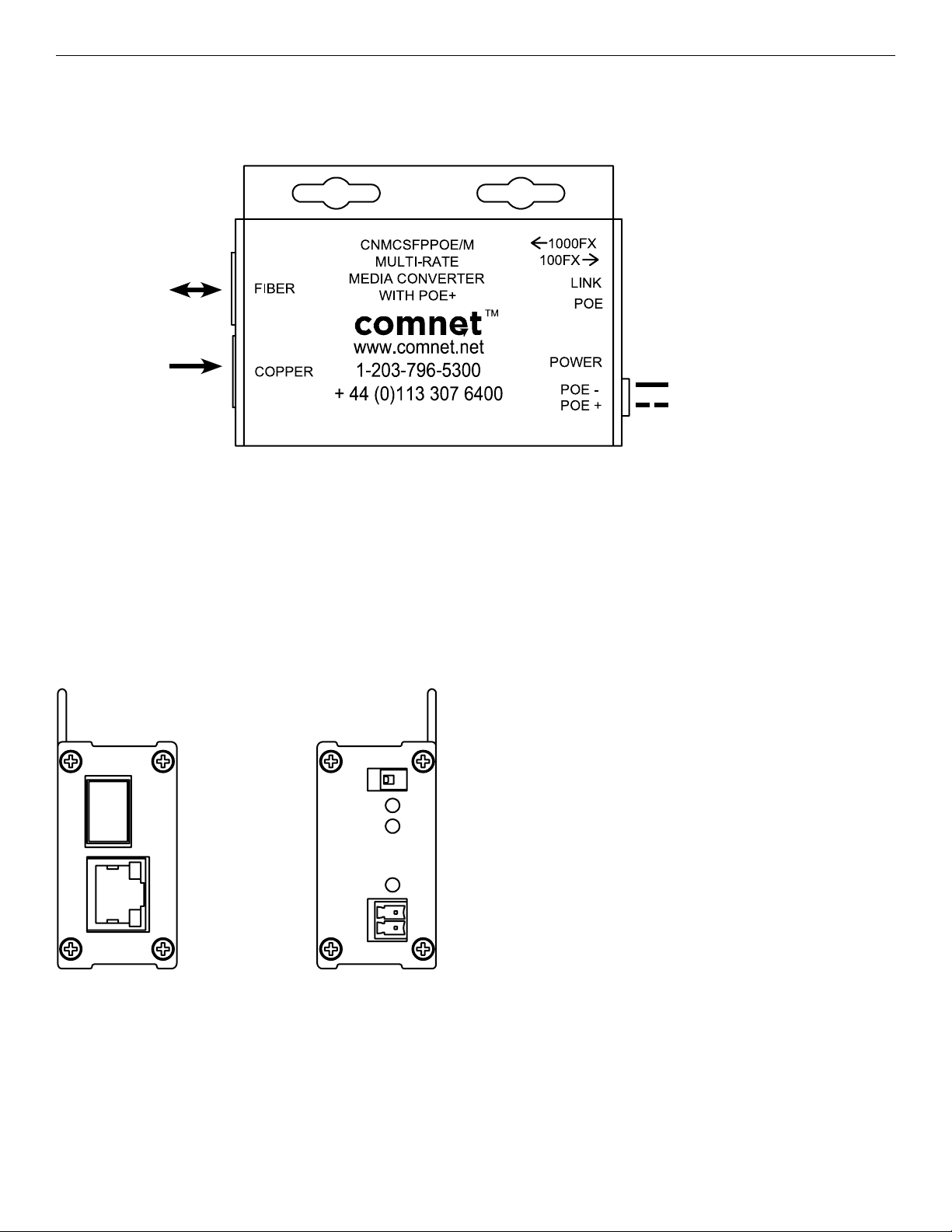
FIGURE 3 – CNMCSFPPOE/M SMALL SIZE UNIT
OPTICAL FIBER
DETERMINED BY
SELECTION OF
SFP MODULE
CAT5e/6
IEEE802.3at
(30W) PoE
BLACK
BLACK WITH WHITE STRIPE
Surface Mount Power:
48 – 57 VDC @ 0.85A
FIGURE 4 – CNMCSFPPOE/M SMALL SIZE UNIT
REAR PANELFRONT PANEL
INS_CNMC[2]SFP[POE][/M]_REV– 06/06/12 PAGE 3TECH SUPPORT: 1.888.678.9427
Page 4

INSTALLATION AND OPERATION MANUAL CNMC[2]SFP[POE][/M] SERIES
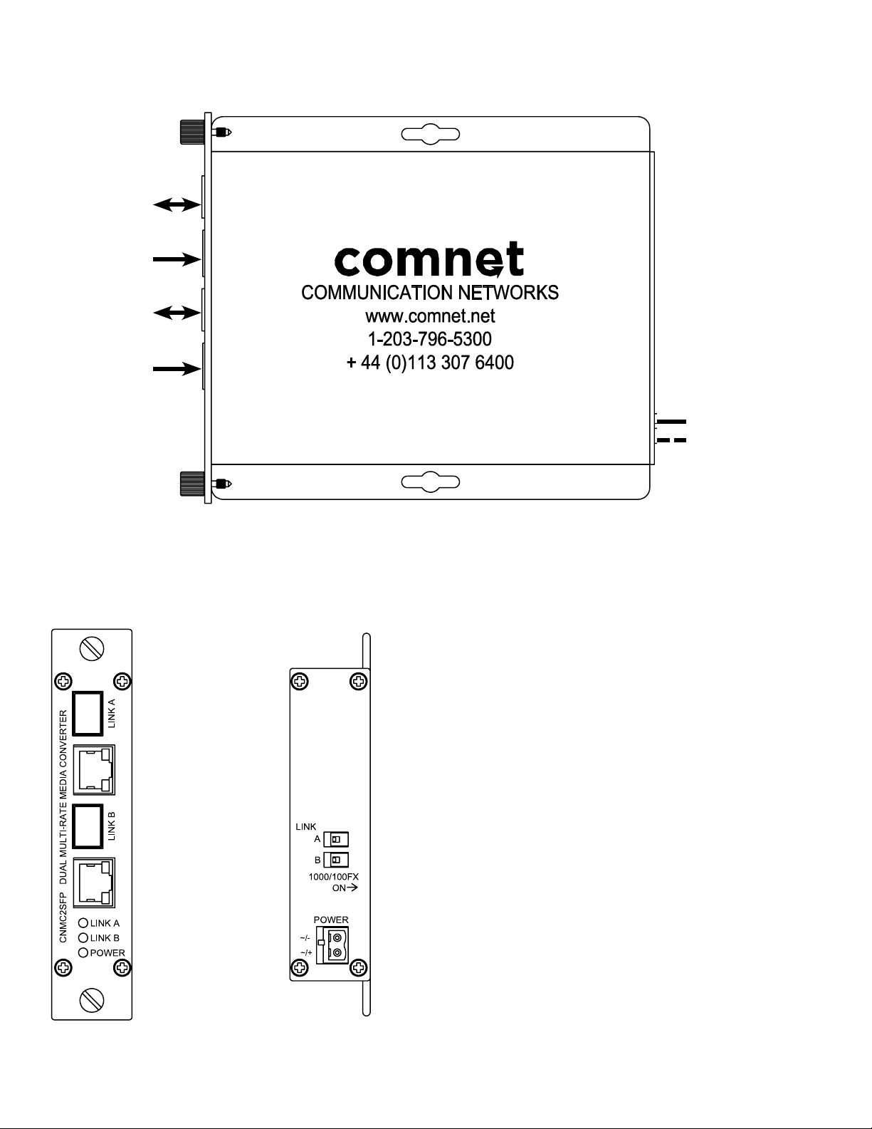
FIGURE 5 – CNMCSFP COMFIT UNIT
OPTICAL FIBER
DETERMINED BY
SELECTION OF
SFP MODULE
CAT5e/6
FIGURE 6 – CNMCSFP COMFIT UNIT
REAR PANELFRONT PANEL
BLACK
BLACK WITH WHITE STRIPE
Surface Mount Power:
9 – 24 VDC @ 200mA max.
OR 24 VAC @ 200mA max.
Rack power: Supplied by Rack
INS_CNMC[2]SFP[POE][/M]_REV– 06/06/12 PAGE 4TECH SUPPORT: 1.888.678.9427
Page 5
INSTALLATION AND OPERATION MANUAL CNMC[2]SFP[POE][/M] SERIES
FIGURE 7 – CNMC2SFP COMFIT UNIT
OPTICAL FIBER
DETERMINED BY
SELECTION OF
SFP MODULE
CAT5e/6
OPTICAL FIBER
DETERMINED BY
SELECTION OF
SFP MODULE
CAT5e/6
FIGURE 8 – CNMC2SFP COMFIT UNIT
REAR PANELFRONT PANEL
BLACK
BLACK WITH WHITE STRIPE
Surface Mount Power:
9 – 24 VDC @ 200mA max.
OR 24 VAC @ 200mA max.
Rack power: Supplied by Rack
INS_CNMC[2]SFP[POE][/M]_REV– 06/06/12 PAGE 5TECH SUPPORT: 1.888.678.9427
Page 6

INSTALLATION AND OPERATION MANUAL CNMC[2]SFP[POE][/M] SERIES
FIBER
POWER
COPPER
LINK/ACT
CNMCSFP/M
MULTIRATE
MEDIACONVERTER
TM
100FX
1000FX
~/-
~/+
FIBER
POWER
COPPER
LINK/ACT
CNMCSFP/M
MULTIRATE
MEDIACONVERTER
TM
100FX
1000FX
~/-
~/+
FIGURE 9 – DIP SWITCH SETTINGS
Position Resulting Data Rate
OFF 1000FX (requires use of Gigabit SFP module)
ON 100FX
NOTE: Select the Data Rate before powering on the unit. After a Data Rate change, re-cycle power to the unit.
FIGURE 10 – LED INDICATORS
LINK COPPER POWER
GREEN
YELLOW
OFF
Solid – No Activity
Blinking – Activity
– Highest Data Rate –
No Link No Link Unit powered down
Solid – No Activity
Blinking – Activity
Unit powered up
FIGURE 11 – POSSIBLE ETHERNET CONFIGURATION
Ethernet IEEE 802.3 Network Element determined by user.
Ethernet IEEE 802.3
Network Element
CAT5e/6 with
RJ45 Connections
100m (328ft)
CNMCSFP/M CNMCSFP/M
Optical Fiber
Determined By
Selection Of SFP
Module
CAT5e/6 with
RJ45 Connections
100m (328ft)
Ethernet IEEE 802.3
Network Element
INS_CNMC[2]SFP[POE][/M]_REV– 06/06/12 PAGE 6TECH SUPPORT: 1.888.678.9427
Page 7
MECHANICAL INSTALLATION INSTRUCTIONS
INSTALLATION CONSIDERATIONS
This fiber-optic link is supplied as a Standalone/Rack module. Units should
be installed in dry locations protected from extremes of temperature and
humidity.
C1-US, C1-EU, C1-AU OR C1-CH CARD CAGE RACKS
CAUTION: Although the units are hot-swappable and may be installed
without turning power off to the rack, ComNet recommends that the power
supply be turned off and that the rack power supply is disconnected from
any power source. Note: Remove electrical connector before installing in
card cage rack.
1. Make sure that the card is oriented right side up, and slide it into the
card guides in the rack until the edge connector at the back of the card
seats in the corresponding slot in the rack’s connector panel. Seating
may require thumb pressure on the top and bottom of the card’s front
panel.
CAUTION: Take care not to press on any of the LEDs.
2. Tighten the two thumb screws on the card until the front panel of the
card is seated against the front of the rack.
WARNING: Unit is to be used with a Listed Class 2 power supply.
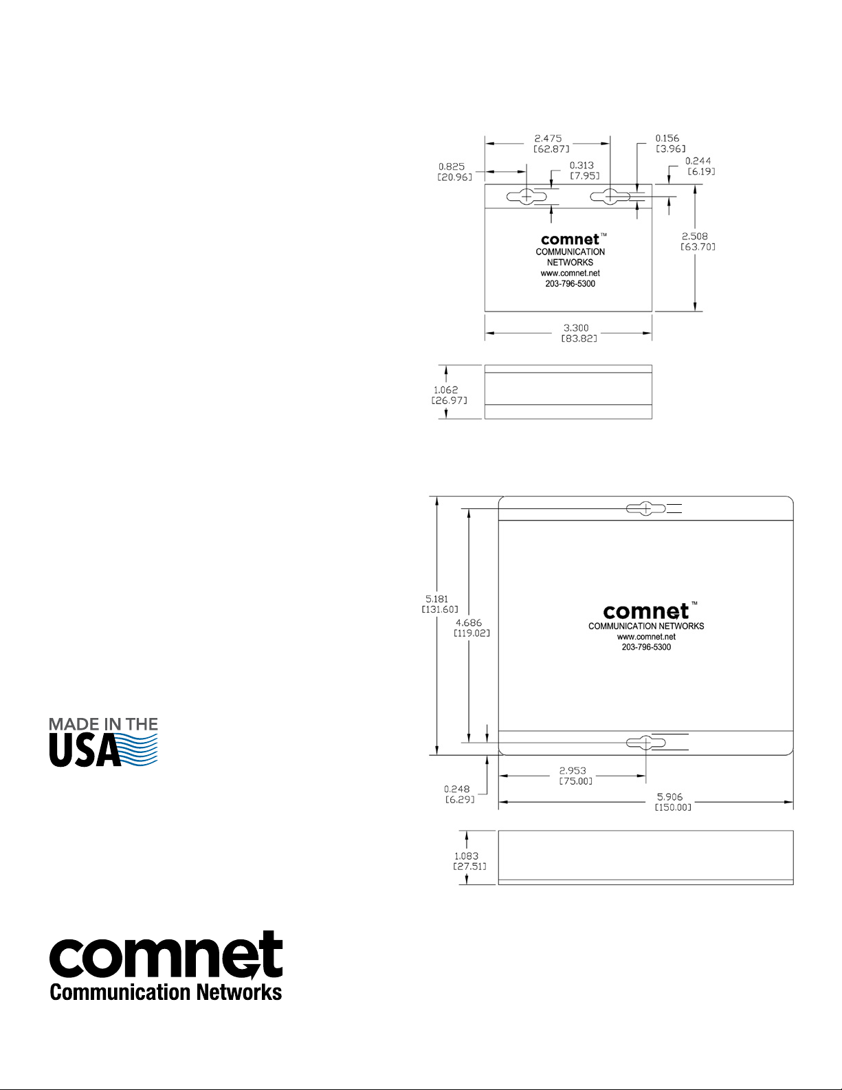
FIGURE A
Dimensions are for a ComNet™ small size module
FIGURE B
Dimensions are for a standard ComNet™ one slot module
IMPORTANT SAFEGUARDS:
A) Elevated Operating Ambient - If installed in a closed or multi-unit rack
assembly, the operating ambient temperature of the rack environment
may be greater than room ambient. Therefore, consideration should
be given to installing the equipment in an environment compatible
with the maximum ambient temperature (Tma) specified by the
manufacturer.
B) Reduced Air Flow - Installation of the equipment in a rack should
be such that the amount of air flow required for safe operation of the
equipment is not compromised.
.156 [3.96 mm]
.313 [7.95 mm]
3 CORPORATE DRIVE | DANBURY, CT 06810 | USA
T: 203.796.5300 | F: 203.796.5303 | TECH SUPPORT: 1.888.678.9427 | INFO@COMNET.NET
8 TURNBERRY PARK ROAD | GILDERSOME | MORLEY | LEEDS, UK LS27 7LE
T: +44 (0)113 307 6400 | F: +44 (0)113 253 7462 | INFO-EUROPE@COMNET.NET
© 2015 Communications Networks Corp oration. All Rights Reserve d. “ComNet” an d the “ComNet Logo” are registered trademarks of Communic ation Networks, LLC.
INS_CNMC[2]SFP[POE][/M]_REV–
06/06/12
PAGE 7
 Loading...