

Page 1
GB
TECHNICAL
MANUAL
MT CT 01
Telephone switchboard Art. 2906
Expansion cards
Art. 2907 - 2908 - 2909 - 2913
07-2006
GROUP S.P.A.
Page 2

MT CT 01
MT CT 01
1
SUMMARY
•
1. SAFETY REGULATIONS page 4
•
2. INTRODUCTION page 4
•
3. INSTALLATION page 8
•
4. BASIC TELEPHONE SERVICES page 23
4.1 Selection of outside line page 23
4.2 Answering an external telephone call page 23
4.3 Selection of a specific outside line page 23
4.4 Call to extension branch page 24
4.5 General call page 24
4.6 Group call page 24
4.7 Selection from telephone directory page 24
4.8 Putting on hold page 25
4.9 Intermediate call page 25
4.10 Conference page 25
4.11 Leaving the conference page 26
4.12 Transfer without offer page 26
4.13 Transfer with offer page 27
4.14 Replying to call waiting page 27
4.15 RIDO Service (DUal ANswer): page 27
4.16 Parking an outside line page 28
•
5. SWITCHBOARD SERVICES page 29
5.1 Day/night service page 29
5.1.1 Description page 29
5.1.2 Activation (OP) page 29
5.2 Automatic day/night service page 29
5.2.1 Description page 29
5.2.2 Configuration page 29
5.2.3 Enabling / disabling (OP) page 30
5.3 Courtesy message page 30
5.3.1 Description page 30
5.3.2 Configuration page 30
5.3.3 Activation / Deactivation (OP) page 31
5.4 Automatic fax recognition page 31
5.4.1 Description page 31
5.4.2 Configuration page 31
5.4.3 Activation / Deactivation (OP) page 31
5.5 Disa page 32
5.5.1 Description page 32
5.5.2 Configuration page 32
5.5.3 Activation / Deactivation (OP) page 32
5.6 Remote relay check page 32
5.6.1 Description page 32
5.6.2 Configuration page 33
5.6.3 Activation / Deactivation (OP) page 33
5.7 Entry phone follow-me page 33
5.7.1 Description page 33
5.7.2 Configuration page 34
5.7.3 Enabling (PO) page 34
Page 3

GROUP S.P.A.
MT CT 01
2
5.8 Line-on-line follow-me page 34
5.8.1 Description page 34
5.8.2 Configuration page 35
5.8.3 Activation / Deactivation (OP) page 35
5.9 Remote SOS line page 35
5.9.1 Description page 35
5.9.2 Configuration page 36
5.10 Filters page 36
5.10.1 Description page 36
5.10.2 Configuration page 37
5.10.3 Configuration with Software Art. 1296 page 38
5.10.4 Activation Filters on branch page 41
•
6 AUXILIARY TELEPHONE SERVICES page 41
6.1 Releasing outgoing calls page 41
6.2 Reply for absent page 41
6.3 Booking extension / outside line page 41
6.4 Capturing call page 42
6.5 Inclusion page 42
6.5.1 Enabling / disabling page 42
6.6 Entering short number (OP) page 43
6.7 Do not disturb page 43
6.8 Diversion to extension page 43
6.9 Call waiting page 44
6.10 Call notified to Branches (OP)
(valid for the Courtesy services – Entry phone follow-me – Line-to-line follow-me) page 44
6.11 Automatic conversation (OP) (valid for the entry phone follow-me and line-to-line follow-me services) page 44
6.12 Alarm clock page 44
6.12.1 Description page 44
6.12.2 Configuration page 45
6.12.3 Activation / Deactivation page 45
6.13 Listening to music on hold (OP) page 45
6.14 Remote programming / Remote firmware uploading (OP) page 45
6.15 Direct outside line connection page 45
6.16 Resetting configurations page 46
6.17 Room monitor page 46
6.18 STS (Supplementary Telephone Services) page 46
6.18.1 R1 page 46
6.18.2 R5 page 46
6.18.3 R2 page 46
6.18.4 R7 page 47
6.19 SMS text messages page 47
•
7 ENTRY PHONE SERVICES page 47
7.1 Call to external unit page 47
7.2 Relay activation page 47
7.3 Checking relay state page 47
•
8 SWITCHBOARD CONFIGURATIONS page 48
8.1 Changing system code page 48
8.2 Defining country page 48
8.3 Selecting music on hold page 49
Page 4

MT CT 01
MT CT 01
3
8.4 Partitions page 49
8.4.1 Activation of partitions page 49
8.4.2 Association of branches – Partitions page 49
8.4.3 Association of lines – Partitions page 49
8.4.4 Association of telephone call buttons – Partitions page 50
8.5 Home / Office operation page 50
8.6 Characterisation of branch page 50
8.7 Enabling / disabling use of lines page 51
8.7.1 Enabling page 51
8.7.2 Disabling page 51
8.8. Direct access to outside line page 51
8.9 Defining number of rings for telephone call page 51
8.10 Groups of branches page 52
8.11 CLI (Caller ID) page 52
8.12 Incoming call operation page 52
8.13 Enabling / disabling lines on branches page 53
8.14 Supplementary Telephone Services page 53
8.15 Characterisation of telephone call buttons page 53
8.16 Enabling / disabling telephone call buttons page 53
8.17 Number of rings for automatic answering services page 54
8.18 Setting the system date page 54
8.19 Setting the system time page 54
•
9 REMOTE MANAGEMENT page 54
•
10 REMOTE CONFIGURATION page 54
10.1 Local teleconfiguration page 54
10.2 Configuration page 55
•
11 REMOTE CONFIGURATION page 55
11.1 Start-up page 55
11.2 Presentation window page 56
11.2.1 Configuration pushbutton PBX page 56
11.2.2 Configuration pushbutton URBANA page 61
11.2.3 Configuration pushbutton DISA page 62
11.2.4 Configuration pushbutton P.E. page 62
11.2.5 RELAY configuration pushbutton page 64
11.2.6 BRANCH configuration pushbutton page 64
11.2.7 Switchboard Enabling Pushbutton page 65
11.2.8 Branch enabling pushbutton page 66
11.2.9 Name Directory Pushbutton page 67
11.2.10 Control pushbuttons and status windows page 67
11.2.11 Programme utilities page 68
•
ANNEX A page 69
•
ANNEX B page 77
•
ANNEX C page 79
•
ANNEX D page 81
•
ANNEX E page 82
•
ANNEX F page 83
Page 5

GROUP S.P.A.
MT CT 01
4
1 SAFETY REGULATIONS
Read the following regulations carefully because they contain important information which regards the
safety of both people and things.
REGULATIONS
Only skilled personnel are allowed access to the inside of the switchboard. It is forbidden to use the telephone
switchboard for purposes other than those for which it has been designed. The electrical installation to which
the switchboard will be connected must conform to the standards in force.
WARNINGS
In case of a fault or malfunction, disconnect the power supply by removing the mains plug or by means of
the mains switch. Only contact skilled personnel for any possible faults. Whilst waiting for the repair or
replacement, the switchboard can operate in emergency mode. To do this, simply disconnect the 220V
power supply.
POWER SUPPLY
The switchboard must be supplied with a mains voltage of 200...250 V ~. It is recommended to dedicate a twopole circuit-breaker for exclusive use of the switchboard.
Should there be a mains power failure, the switchboard goes into EMERGENCY mode. In this way, the first
telephone line is redirected directly to branch one, whereas the second line, if expansion 2908 is mounted,
goes to branch two. Operation of the telephone service is therefore guaranteed, whereas the entry phone
service remains excluded until return of the power supply.
MAINTENANCE
Any maintenance operations on the switchboard must be carried out by skilled personnel.
2 INTRODUCTION
G
ENERAL INFORMATION
The system is able to manage:
• Self-learning of the expansion cards.
• Putting an outside line or an extension on hold by means of button R.
• Call waiting for extension, entry phone and telephone calls.
• Conference with three extensions or two extensions + outside line.
• Configuration of a branch as FAX, ANSWER PHONE, TELEPHONE FAX or simple TELEPHONE.
• Programming of the number of branch bell rings following an entry phone call.
• Configuration of max. 5 groups of telephones.
• General internal or group call.
• Room monitor for room control.
• Independent service alarm clock for each branch.
• Possibility of making systems with two partitions.
• Separate DAY/NIGHT operation for each partition. The change of scenario takes place manually by keying
in a code or automatically according to pre-recorded times.
• Management of max. 5 simultaneous conversations. For example, with a switchboard equipped with 2 outside
lines, 8 branches and the entry phone card, you could have 2 pairs of branches having an internal conversation,
2 branches in conversation with the outside line and 1 branch in conversation with the external unit.
Page 6

MT CT 01
MT CT 01
5
• HOME/OFFICE operation to make it possible to simplify operation of the switchboard.
• Selection from a branch of the first free outside line or of a specific outside line.
• Directory with 40 common speed dialling numbers. It is possible to define speed dialling numbers as SOS.
These will not be subject to any filters on the area codes activated in the switchboard.
• Filter on telephone calls for type of carrier and area codes.
• Access to TELECOM services, including the SMS message ones.
• Direct connection of a branch to the outside line just by lifting the microtelephone.
• Management of the caller ID (call identifier- standard ETSI).
• Choice among 3 pieces of music on hold (Spring by Vivaldi, Catalan Melody or Over the Rainbow), with the
possibility of listening to these.
• Activation, also remotely, of 3 auxiliary relays, with the possibility of controlling their state.
• Direct connection to the outside line for the telephones connected to branches T1 and T2.
• Connection to a PC by means of RS232 to speed up programming.
• Remote SOS line function which, in case of an alarm, calls up to 5 programmed telephone numbers and
sends a pre-recorded message when there is a reply.
• Follow-me function from telephone line to telephone line.
• Follow-me function from external unit entry phone to telephone line (follow-me).
• Possibility of configuring an entry phone call input as “floor door call”.
• "Courtesy message" function.
• Firmware updating (local or remote) and switchboard programming remotely by means of PC or telephone.
• Division of the programming in CONFIGURATIONS and ENABLEMENTS. All the CONFIGURATIONS must
take place after inserting a personalisable password and only from branch 1.
• Automatic MODEM and FAX recognition.
• DISA function for automatic routing of a call.
• Selection of the country of use to modify some of the switchboard setting and therefore adapt to European
markets.
• Reply for absent on extension or telephone call addressed to the individual extension.
• “Do not disturb” function.
• Follow-me function on extension, either immediate or after x rings.
• Possibility of disabling the filter on the carriers and the area codes of the outside line calls by means of a
code + personalisable password.
• Booking an engaged extension.
• Booking an engaged outside line.
• Transfer of a telephone call with or without offer.
• “Capturing call“ service.
• Possibility of including yourself in a conversation if the branch called is enabled.
• RIDO service for putting multiple lines on hold.
Table 1: Main performances of the switchboard and of the expansions
ARTICLE SERVICES OFFERED
2906 basic card Basic telephone services, day night service, automatic day night
service, alarm clock, filters, STS, automatic fax recognition
2907 branch expansion 4 branches are added
2908 outside line expansion 1 outside line, line-on-line follow-me is added
2909 traditional entry phone expansion Entry phone services, entry phone Follow-me, remote relay check
2913 message expansion Courtesy message, DISA, remote SOS line
Page 7

GROUP S.P.A.
MT CT 01
6
DESCRIPTION OF THE MAIN FUNCTIONS
PARTITIONS:
This is meant as the possibility of distributing the switchboard resources over 2 distinct systems called
PARTITIONS. Outside lines, telephones branches or telephone call buttons can be associated to each one to
allow the same living unit to be divided into two distinct areas.
GROUPS OF BRANCHES:
This is meant as the possibility of dividing the telephone branches connected to the switchboard into groups. It
is possible to define up to a maximum of 5 of these, where a branch can belong to different groups.
(See paragraph 8.10 to create a group, see paragraph 2.5 for the call.)
CHARACTERISATION OF THE TELEPHONE BRANCH: (See paragraph 8.6)
The telephone branch connected to the switchboard can be configured so that it is recognised as:
- Normal BCA telephone
- Operator Post telephone. This has authorisation to carry out all enablement / disablement operations of the
switchboard services (COURTESY MESSAGE - FAX RECOGNITION – DISA etc…)
- Fax. The incoming calls recognised as Fax will be routed over this branch.
- Fax Telephone. Incoming calls of both Fax and vocal type are routed over this. It is a configuration suitable
for multi-purpose apparatus.
- Answer phone
DAY / NIGHT SCENARIOS:
It is possible to establish two operating scenarios, defined as DAY and NIGHT SCENARIO, which differ in:
- Different configuration of the incoming or outgoing outside lines per individual the branch.
- Different distribution of the entry phone calls over branch telephones.
- Different characterisation of the extension branches.
- Different activation of the COURTESY MESSAGE – ENTRY PHONE FOLLOW-ME and LINE-TO-LINE
FOLLOW-ME services.
Passing from one scenario to the other takes place manually on keying in a command (See paragraph 5.1), or in
automatic mode according to times established by the user (See paragraph 5.2).
HOME / OFFICE OPERATION: (See paragraph 8.5)
It is possible to set the switchboard so that it functions in HOME or OFFICE mode:
- HOME: this simplifies the call operations on an outside line, reply for absent and call capturing. It is
recommended for home applications.
- OFFICE: this is the mode recommended for office and company applications and is the factory setting of the
switchboard.
DISA:
This is the service allowing automatic routing of the call from the outside line. The caller can select the
branch or groups of branches to converse with directly by means of a DTMF code (See paragraph 5.5).
COURTESY MESSAGE:
This is the service for which the switchboard gives a pre-recorded “welcoming message” pre-recorded, when a
call arrives on the outside or door entry line (See paragraph 5.3).
Page 8

MT CT 01
MT CT 01
7
FOLLOW-ME:
This is the service which allows an entry phone call on the outside line to be transferred to a number
programmed by the user (See paragraph 5.7).
REMOTE SOS LINE:
This is the service which allows a list of telephone numbers to be called if an alarm signal is present on the
switchboard (See paragraph 5.9).
LINE-TO-LINE FOLLOW-ME:
This is the service which allows a call from an outside line to be transferred on the other outside line to a
telephone number programmed by the user (See paragraph 5.8).
AUTOMATIC FAX RECOGNITION:
This is the service allowing the fax on a branch characterised as Fax or Telephone Fax to be routed
automatically (See paragraph 5.4).
REMOTE RELAY CHECK:
This is the service which allows the relays present on the entry phone expansion card art.2909 to be activated
from the outside line and possibly to control their state of closed or open (See paragraph 5.6).
LOCAL PROGRAMMING:
This allows configuration of the switchboard to be carried out by means of a RS232 serial line, using the
Configuration Manager software Art.1296.
REMOTE MANAGEMENT:
This allows both updating of the firmware and configuration of the switchboard from an outside line (See
paragraph 9).
FLOOR DOOR CALL:
The signal of an entry phone call present on terminals S1 / S2 / S3 / S4 is treated as a simple signal instead of
the standard call which foresees audio connection with the external unit (See paragraph 8.17).
RIDO ( RIsposta DOppia [DUal ANswer] ):
This is the service allowing branch 801 which is in the situation of intermediate call, to serve a further call
coming from an outside line.
TYPES OF APPARATUS
The switchboard can operate with BCA keypad telephones (decade or DTMF), cordless (CT1, CT2, DECT),
answer phones, faxes, etc.
Furthermore, it is possible to connect the COMTEL telephone Art. 1926 - 4921 - 4922 in the Operator Post
version or branched user.
Page 9
GROUP S.P.A.
MT CT 01
8
3 INSTALLATION
R
ECOMMENDATIONS
The switchboard must be installed in a closed room, with a temperature which varies between 0 and 40 °C and
with non-condensing relative humidity between 0% and 85%.
For the requirements of authorisation from the telephone carrier company to be satisfied, the switchboard must
be connected to the telephone jack by means of a telephone cable and must have a removable plug. Do not
run the telephone cables near the 220 V network.
GENERAL INFORMATION
The configuration commands are carried out from branch 01 with a multi-frequency telephone. As in all the
operations foreseen on this switchboard, the command is only accepted if the continuous command waiting
tone is present in the receiver. If the timed dissuasion tone is present you must hang up the receiver and
repeat the operation.
BASIC SWITCHBOARD 2906
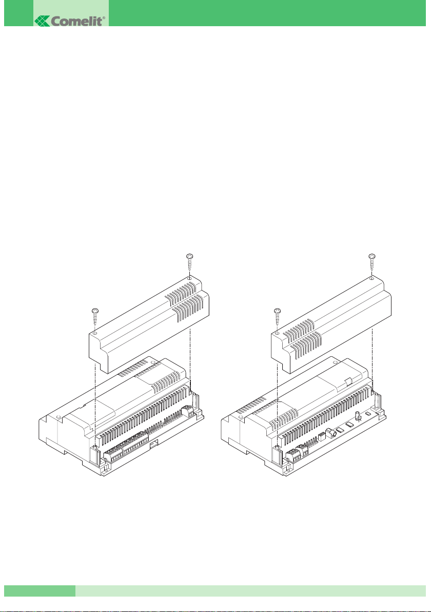
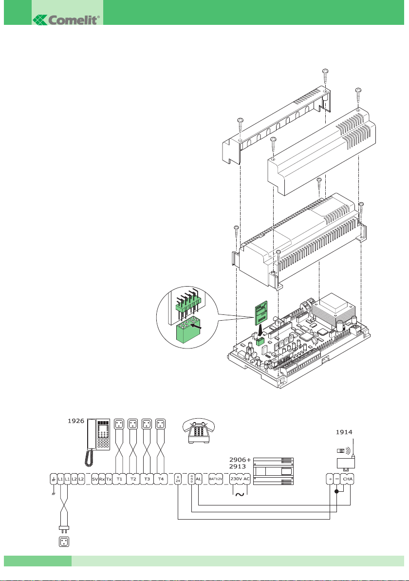
The switchboard is contained in a 12 DIN module box. To be able to access the connection terminals, remove
the side cover as shown in Fig. 1.
Fig. 1: access to the terminal board compartment
The plug of mains power supply must be disconnected during the system cabling and connection operations.
Connection to the telephone apparatus (Telecom lines and branch apparatus) must be carried out using
a telephone cable. The polarity of the connection has no importance and can be either mains side or
branch side.
The basic installation diagram is given below (Diagram 1).
The connection terminals on the interface are indicated in Table 2.
Page 10

MT CT 01
MT CT 01
9
Table 2: Switchboard terminals and associated expansion cards
TERMINAL FUNCTION EXPANSION
EARTH Earth terminal
L1 - L1 Terminals of line 1
L2 - L2 Terminals of line 2 2908
5V 5V power supply terminal for telephone OP
RX RX terminal for OP
TX TX terminal for OP
T1 Terminals of branch 1.
T2 Terminals of branch 2.
T3 Terminals of branch 3.
T4 Terminals of branch 4.
T5 Terminals of branch 5. 2907
T6 Terminals of branch 6. 2907
T7 Terminals of branch 7. 2907
T8 Terminals of branch 8. 2907
2 Sound towards external unit entry phone microphone 2909
3 Sound towards external unit entry phone loudspeaker 2909
4 Entry phone system ground 2909
S1 Entry phone 1 call input signal 2909
S2 Entry phone 2 call input signal 2909
S3 Entry phone 3 call input signal 2909
S4 Entry phone 4 call input signal 2909
+24 Output voltage +24Vdc ( max 30mA ) 2909
GND Ground
AL Alarm input for remote SOS line service 2913
N1 Relay contact 10A ( can be activated with DTMF digit # ) 2909
C1 Relay contact 10A ( can be activated with DTMF digit # ) 2909
N2 Relay contact 1A ( can be activated with DTMF digit * ) 2909
C2 Relay contact 1A ( can be activated with DTMF digit * ) 2909
N3 Relay contact 1A ( can be activated with DTMF digit 5 ) 2909
C3 Relay contact 1A ( can be activated with DTMF digit 5 ) 2909
230VAC Mains power supply 230V (on the terminal external poles)
BAT 12V Input for emergency battery (max 80mA)
Jack Connector Input for external music
Page 11
GROUP S.P.A.
MT CT 01
10
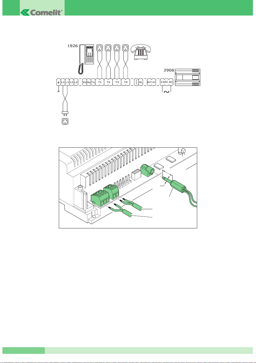
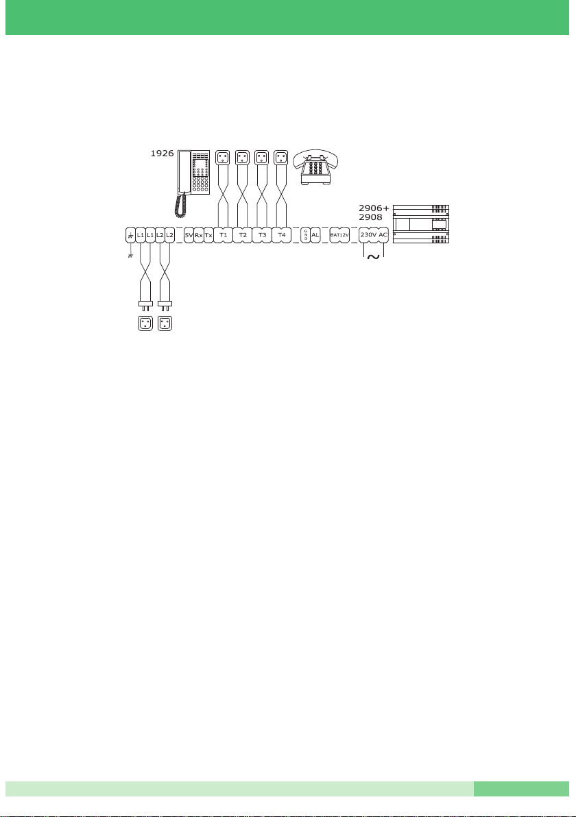
Diagram 1 - CT 08A: System with 1 analog line and 4 branches
Fig. 2: 230VAC power supply connection, 12V battery, Jack for external music.
+
--
BAT 12V
230V AC
Jack for external music
ø3,5mm
L=14,5mm
Page 12

MT CT 01
MT CT 01
11
EXPANSION CARD FOR ANALOG OUTSIDE LINE ART. 2908
This card allows a second Telecom telephone line to be connected to the switchboard.
A single expansion 2908 can be inserted for a maximum of two telephone lines. In the case of a power supply
failure, the second telephone line is automatically connected on branch T2.
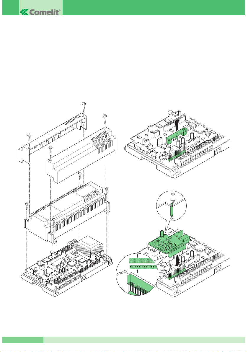
Installation of the expansion
Before proceeding, the 220V voltage to the switchboard must be removed.
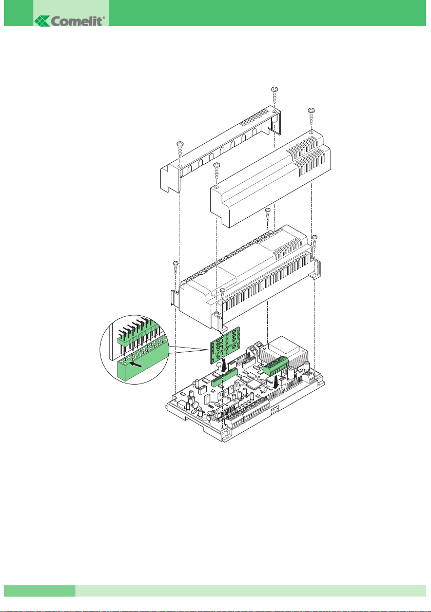
At this point, according to what is indicated in Fig. 3:
1. Remove the side covers and the central cap from the switchboard.
2. Remove the cap of the connector which will house the card.
3. Insert card 2908.
4. To ensure card stability, it is necessary to fix it using the spacer provided.
5. Put back the covers and the cap.
6. Put back the 220V power supply.
7. The card will be recognised automatically.
Default configuration
Once the card is inserted, the configuration of the branches in relation to line 2 is as follows:
•
All the branches are enabled to receive calls from line 2
• All the branches are enabled to outgo over line 2
What needs to be programmed in the case of card replacement:
No programming is needed - the configurations / enablements of the second outside line are kept.
ISDN 1 SYSTEM BASIC ACCESS WITH TELECOM
NT
NT
1
1PLUS INTERFACE
In the case of a telephone system with two ISDN lines (basic access) with only one telephone number and a
single group of branches which reply and call on line 1 and 2 indifferently, it is necessary to configure the
Telecom NT1 PLUS interface appropriately.
Here is an example: imagine that the user the user Rossi has a basic ISDN access with NT1 PLUS interface.
On the two analog lines (1 and 2) of the interface a 2906 switchboard is attached complete with second
expansion line. The telephone number of Mr Rossi is 06-760000.
With the default configuration of NT1 PLUS, by calling number 06-760000 both lines 1 and 2 ring. The first
which is used for the reply frees the second.
For correct use of the telephone switchboard it is necessary to programme the NT1 plus so that by calling
number 06-760000 only one of the two lines rings - the first which is found to be free.
To programme the Telecom interface, extended configuration of incoming calls must be carried out:
par. 6.1.1.1 of NT1 PLUS manual
•
disconnect the mains power supply
• open the terminal board compartment and disconnect the line telephone cable
• reconnect the mains power supply
• connect a telephone to the analog output a/b 1 or a/b 2
par. 6.2.1 of NT1 PLUS manual
•
digit the multi-frequency keys # * # #*#
Page 13
GROUP S.P.A.
MT CT 01
12
par. 6.2.2 of NT1 PLUS manual
•
carry out the assignment command: * 05*1#
after the vocal confirmation of command acceptance, you can reconnect the line telephone cable:
•
disconnect the mains power supply
• open the terminal board compartment
• connect the line telephone cable
• close the terminal board compartment
• connect the mains power supply
NOTE: the above steps refer to the AETHRA installation manual of NT1 plus rev. 0.
Fig. 3: installation of second line expansion
A
B
A
B
Page 14
MT CT 01
MT CT 01
13
SYSTEM WITH TWO TELEPHONE LINES
Diagram 3 shows the installation diagram of a system with two telephone lines and four branches.
Diagram 3 - CT 09A: System with 2 analog lines and 4 branches
BRANCH EXPANSION CARD ART. 2907
By inserting an expansion card 2907, it is possible to expand the number of extension branches to 8.
Installation of the expansion
Before proceeding, the 220V voltage to the switchboard must be removed. At this point, according to what is
indicated in Fig. 4 :
1. Remove the side covers and the central cap from the switchboard.
2. Insert card 2907 in the special housing.
BE CAREFUL to respect the correct insertion polarity.
3. Put back the covers and the cap.
4. Reconnect the 220V voltage to the switchboard.
5. The card will be recognised automatically.
Default configuration
Once the card is installed and configured, configuration of the branches added is as follows:
•
They are enabled to receive and call over the lines present in the switchboard
•
If the entry phone expansion (2909) is present, they are enabled to receive calls from the external unit
•
They are configured as user branches
What needs to be programmed in the case of card replacement:
No programming is needed - the configurations / enablements of the branches are kept.
Page 15
GROUP S.P.A.
MT CT 01
14
SYSTEM WITH EIGHT BRANCHES
Diagram 4 shows the installation diagram of a system with two lines and 8 branches.
Fig. 4: Installation of card 2907
Page 16
MT CT 01
MT CT 01
15
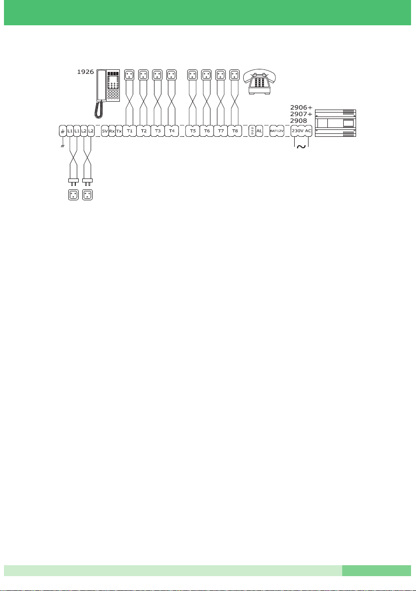
Diagram 4 - CT01A: System with 2 analog lines and 8 branches
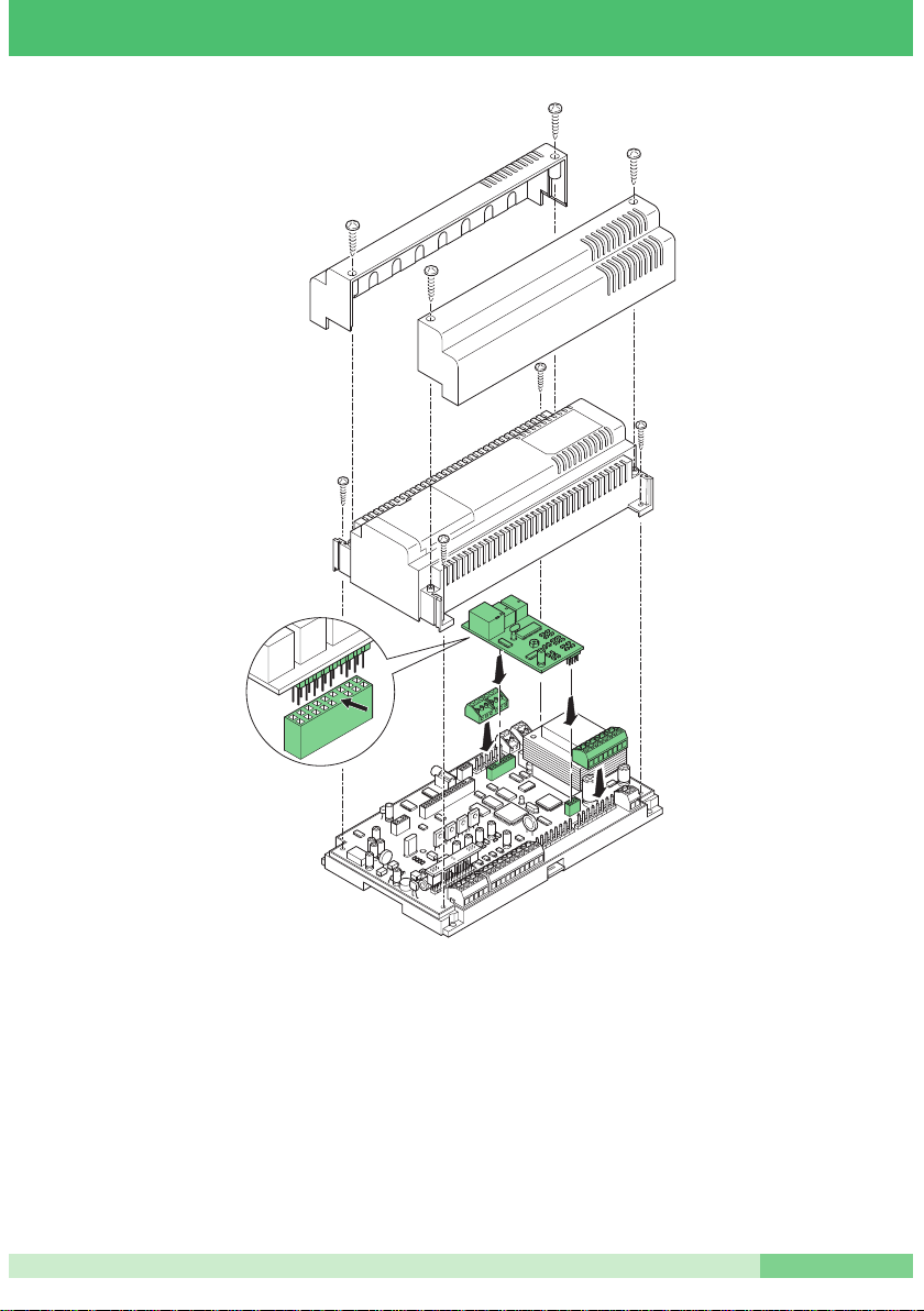
ENTRY PHONE INTERFACE EXPANSION CARD ART. 2909
This card allows the telephone switchboard to be connected to an entry phone system. In this way it is
possible to reply to entry phone calls directly from the telephones and control door opening, turning on lights,
etc. from these.
It is possible to manage four external unit call inputs or, alternatively, to configure these as floor door call.
Installation of the expansion
Before proceeding, the 220V voltage to the switchboard must be removed. At this point, according to what is
indicated in Fig. 5:
1. Remove the side covers and the central cap from the switchboard.
2. Insert card 2909 in the special housing.
3. Put back the covers.
4. Reconnect the 220V voltage to the switchboard.
5. The card will be recognised automatically.
Default configuration
Once expansion 2909 is installed, the configuration is as follows:
•
Four external unit calls are configured
•
All the telephones are enabled to receive the entry phone calls
•
The Door Opener time is one second
•
The auxiliary relay outputs are monostabl
What needs to be programmed in the case of card replacement:
Adjustment of the external unit volumes is necessary.
Page 17
GROUP S.P.A.
MT CT 01
16
Relay controls
With the microtelephone lifted, it is possible to activate the following relay outputs:
Table 4: Description of the relays present on card 2909
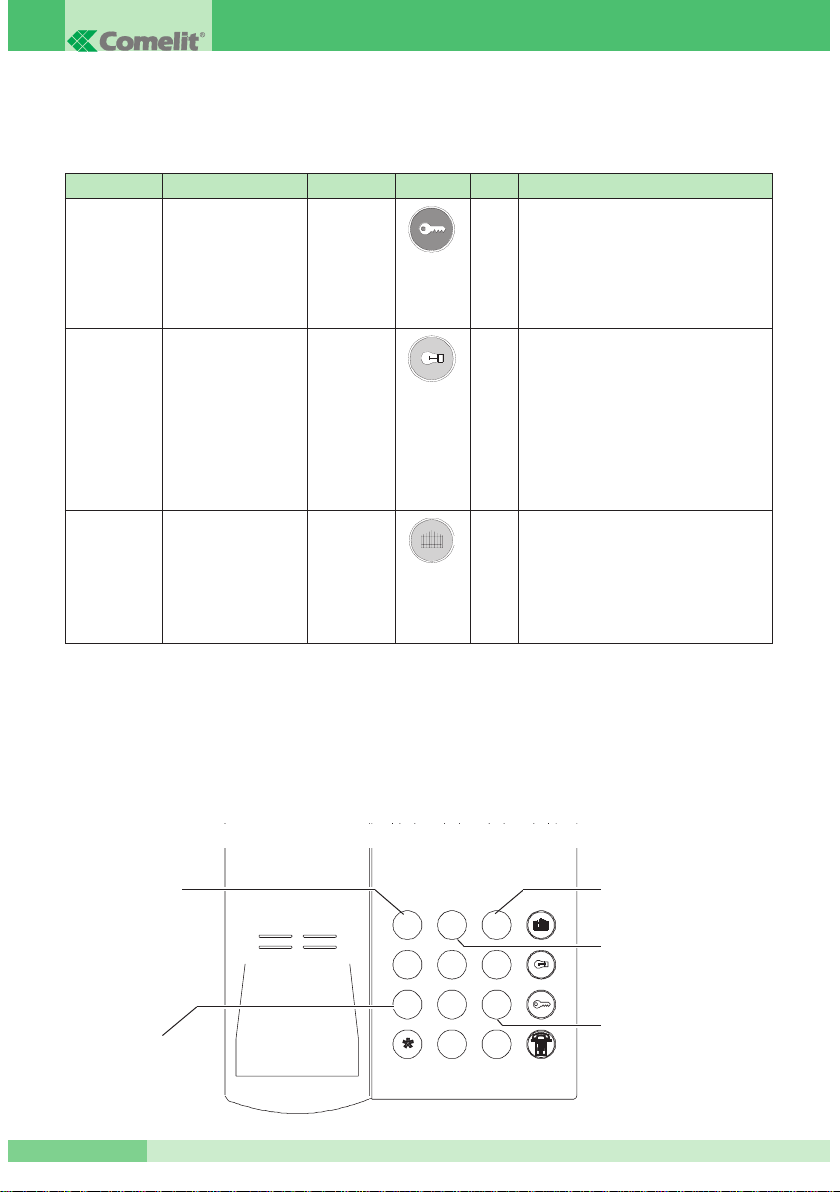
Adjustment of external unit volume
The sound of the entry phone interface has been designed in full-duplex mode, according to which the person
speaking can also listen to their interlocutor. It has volumes preset by Comelit , and once a conversation with the
external unit is set up, it is in nay case possible to adjust them directly from the telephone by using buttons 1 – 7 – 3
– 9, according to the method shown in the figure below. 17 adjustment levels are possible, and each time the button
is pressed, the volume is changed by 1 level. It is necessary to digit number 2 to store the volume levels reached.
TERMINAL DESCRIPTION POWER COMTEL BCA NOTES
N1 – C1 “Door Opener” Relay Max # The output can be configured
Control 7 A as bistable or as monostable.
80Vdc – This output can be activated
50Vrms remotely remote on a call from
the telephone line.
N2 – C2 “Stair Lights” Relay Max * The output can be configured as:
control 1A - - Bistable or as monostable.
24Vdc – - Internal Lighting-up use or generic use.
120Vrms If configured as Internal Lighting-up,
the output cannot be activated
remotely with the Relay Remote
Check service.
N3 – C3 “Gate opener” Relay Max 5 The output can be configured as
1A -
bistable or as monostable.
24Vdc –
This output can be activated
120Vrms remotely remote on a call from the
telephone line.
#
987
4
5
6
12
3
To increase the
volume in the
External unit –
Extension branch
direction
To increase the volume
in the
Extension branch –
External unit direction
Storage of the
volumes reached.
To decrease the volume
in the
Extension branch –
External unit
To decrease the volume
in the External unit –
Extension branch
direction
Page 18
MT CT 01
MT CT 01
17
Fig. 5: Installation of entry phone expansion
Page 19
GROUP S.P.A.
MT CT 01
18
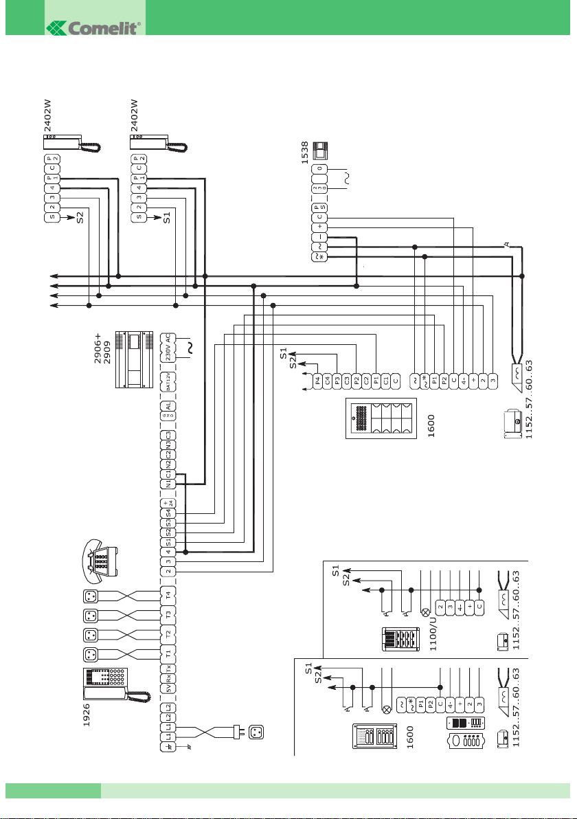
Diagram 5 - CT 02A: COMELIT entry phone system with 4 calls from external unit
Page 20
MT CT 01
MT CT 01
19
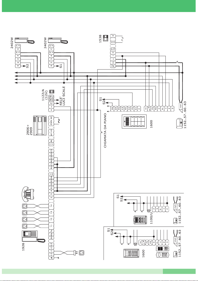
Diagram 6 - CT FA: COMELIT entry phone system call from external unit, floor door call, Stair Lights control
Page 21
GROUP S.P.A.
MT CT 01
20
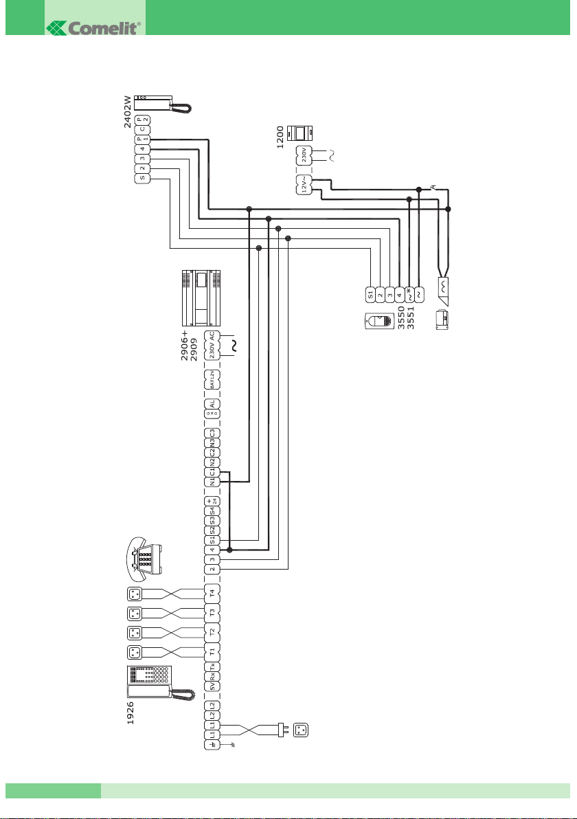
Diagram 7 - CT 10A: Door entry telephone System with IDEALKIT
Page 22
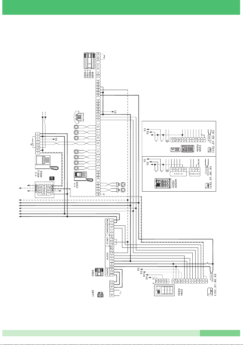
Diagram 8 - VCT 01A: Video – door entry telephone System with traditional cabling.
MT CT 01
MT CT 01
21
Page 23
GROUP S.P.A.
MT CT 01
22
MESSAGE EXPANSION CARD ART. 2913
Addition of this card allows the messages needed for correct operation of some switchboard services to be
recorded, see Courtesy message , DISA etc..
Installation of the expansion
Before proceeding, the 220V voltage to the switchboard must be removed.
At this point, according to what is indicated in Fig. 6.
1. Remove the side covers and the central cap from the switchboard.
2. Insert card 2913 in the special housing.
3. Put back the covers and the cap.
4. Reconnect the 220V voltage.
5. The card will be recognised automatically.
Default configuration
No message is recorded.
What needs to be programmed in the case of card replacement:
It is necessary to record the desired messages.
Diagram 13 - CT GA: System with radio receiver for remote SOS line
Page 24
MT CT 01
MT CT 01
23
4 BASIC TELEPHONE SERVICES
4.1 S
ELECTION OF OUTSIDE LINE
The first free line is selected. It is only possible to select lines of the same partition. The HOME version has
direct access to the outside line as default.
The following alternatives are possible:
• On pressing button 0, the switchboard sends the engaged tone when the line or lines on which the branch is
enabled are already busy.
• If the branch generates some digits in line which are part of the disabled area codes, the dissuasion tone is
received in the receiver.
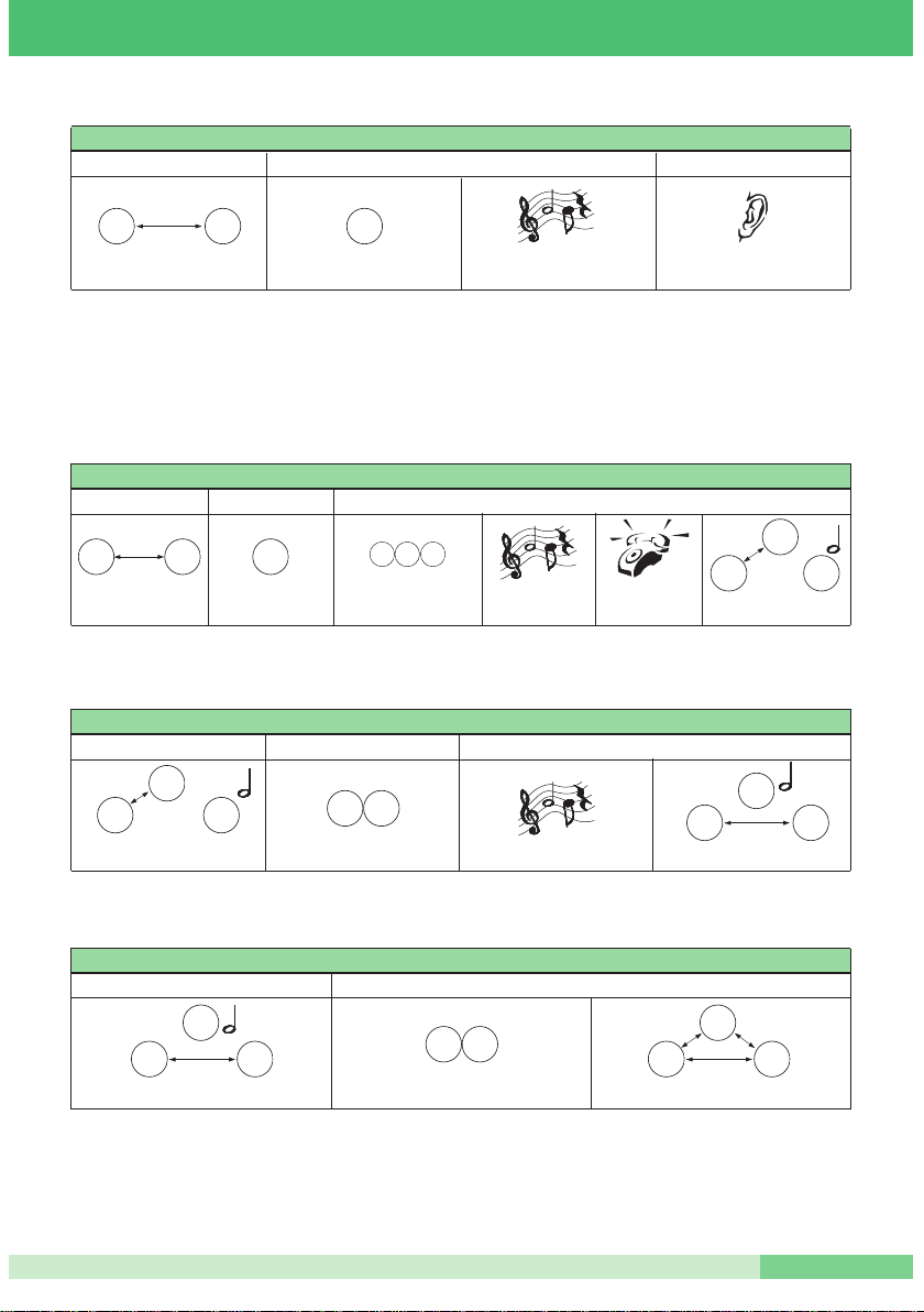
4.2 ANSWERING AN EXTERNAL TELEPHONE CALL
4.3 SELECTION OF A SPECIFIC OUTSIDE LINE
It is only possible to select lines of the same partition.
The HOME version has direct access to the outside line as default.
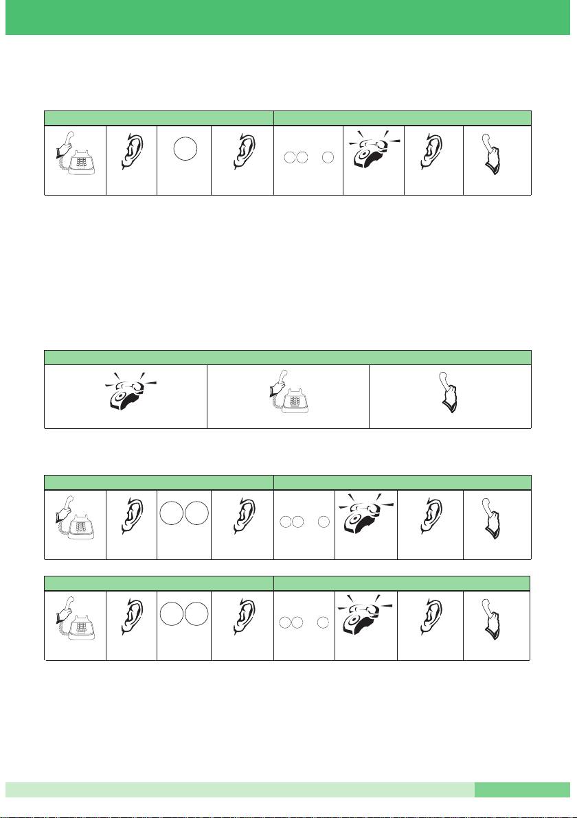
EXAMPLE
0
I lift the receiver
Access to the
outside line
Continuous
tone
Access to the outside line from a branch Selection of the remote user
Call tone
Conversation
Invitation tone
to select
The remote
user rings
Telephone
number
0 3 9
...
Bla
bla
I lift the receiver
The branch rings on the call
The telephone rings
Conversation
Bla
bla
EXAMPLE
9 1
I lift the receiver
Access to
line 1
Continuous
tone
Access to outside line 1 from a branch
Selection of the remote user
Call tone
Conversation
Invitation tone
to select
The remote
user rings
Telephone
number
0 9 1
...
Bla
bla
EXAMPLE
9 2
I lift the receiver
Access to
line 2
Continuous
tone
Access to outside line 2 from a branch
Selezione dell’utente remoto
Call tone
Conversation
Invitation tone
to select
The remote
user rings
Telephone
number
0 9 2
...
Bla
bla
Page 25
GROUP S.P.A.
MT CT 01
24
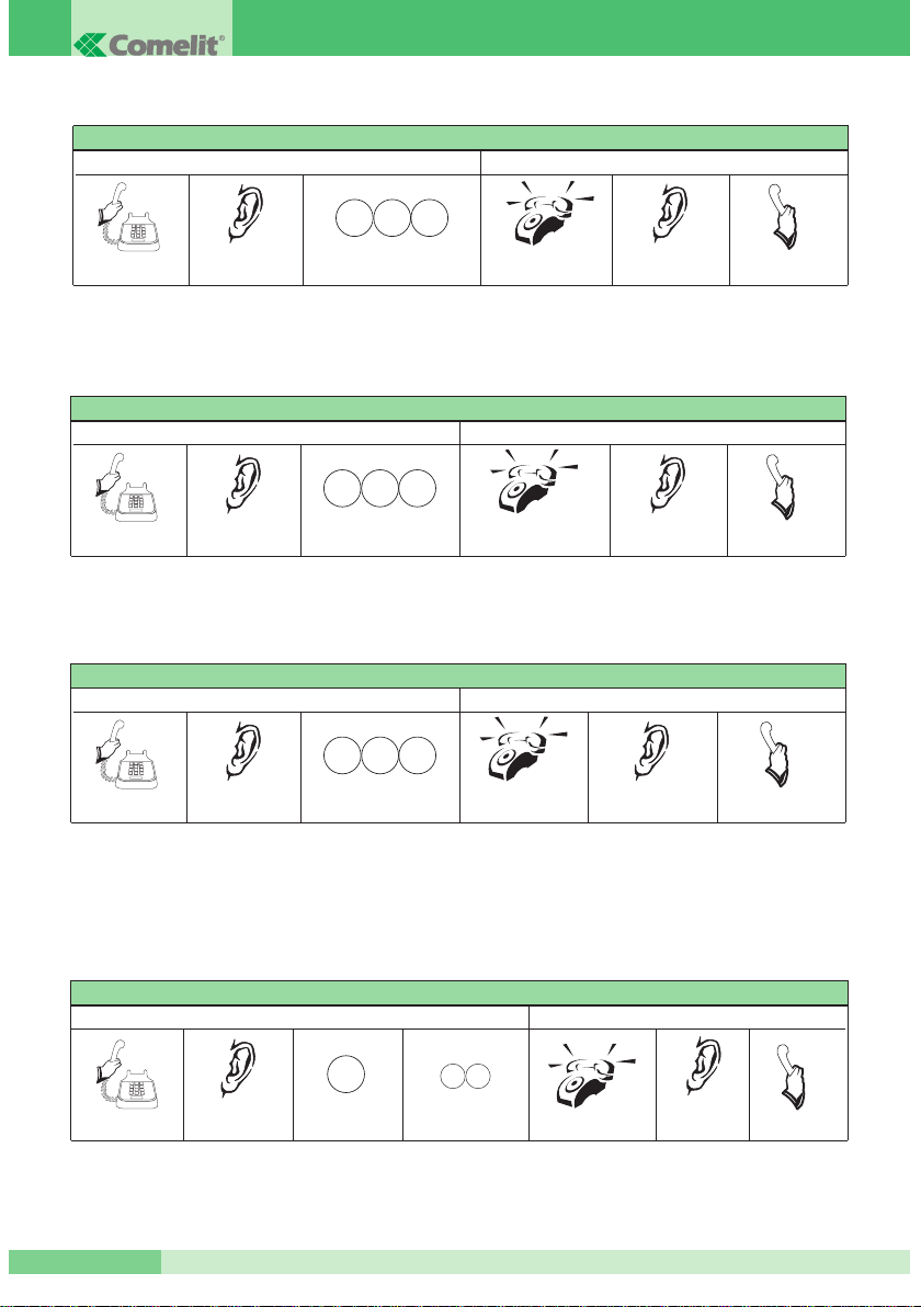
4.4 CALL TO EXTENSION BRANCH
4.5 GENERAL CALL
This means the possibility of a branch to call all the branches of its own partition simultaneously.
4.6 GROUP CALL
This service can only be provided after having created a group of branches (See paragraph 8.10).
4.7 SELECTION FROM TELEPHONE DIRECTORY
The telephone switchboard has a memory 40 (from 01 to 40) speed dialling numbers with a max. of 16 digits
each. All the branches can recall the speed dialling numbers, but only the operator posts can programme them
(See paragraph 6.7). The selection is ignored if the speed dialling number has not been programmed.
In the case of partitions, a directory consisting of 20 speed dialling numbers is assigned to each one.
Conversation
All the
branches ring
Call tone
Bla
bla
STANDARD BCA TELEPHONE
Call Conversation
Continuous
tone
Button 800
I lift the receiver
8 0 0
STANDARD BCA TELEPHONE
Call
Conversation
Continuous
tone
The branches belon-
ging to the group ring
Buttons 8 and 3 followed by the
group desired from 1 to 5 (e.g. 5)
Call tone
I lift the receiver
Bla
bla
8 3 5
EXAMPLE
Conversation
The extension called
rings
Call tone
Bla
bla
STANDARD BCA TELEPHONE
Call Conversation
Continuous
tone
Button 8 followed by the extension
desired from 01 to 08 (e.g. 04)
I lift the receiver
8 0 4
Button 4
Speed dialling number
from 01 to 40 (e.g. 19)
EXAMPLE
149
STANDARD BCA TELEPHONE
I recall the speed dialling number Conversation
Continuous
tone
I lift the receiver
The remote user rings
Call tone
Bla
bla
Conversation
EXAMPLE
Page 26
MT CT 01
MT CT 01
25
4.8 PUTTING ON HOLD
This operation is valid both for internal and telephone calls.
4.9 INTERMEDIATE CALL
This means the possibility by branch A of putting an outside line / extension branch B on hold and making a
second call to an outside line / extension branch C, or a command to an entry phone. It is carried out by
following the table below:
By keying in the R2 sequence, branch A can speak alternately (toggle) with user B (C is put on hold) or
with user C (B is put on hold).
4.10 CONFERENCE
R
Telephone waiting for commands
Continuous tone
on A
EXAMPLE
Conversation between
branch A and B
A presses:
FLASH button, R
STANDARD BCA TELEPHONE
Conversation Putting B on hold
Music on hold
on B
EXAMPLE
Music on hold
on B
Conversation
with extension C
EXAMPLE
Conversation between
branch A and B
A presses:
FLASH button, R
STANDARD BCA TELEPHONE
Conversation Putting B on hold
Putting extension B on hold and extension C call
Button 8 followed
by the extension desired
from 01 to 08 (e.g. 04) (C)
Extension 04 (C)
rings
8 0 4
Music on hold on C
Conversation with extension B
EXAMPLE
Conversation between branch A
and C with B on hold
A dials the R2 sequence
STANDARD BCA TELEPHONE
Conversation
Putting C on hold
Putting C on hold and recovery of B
R 3
EXAMPLE
Conversation between branch A - B and C on hold
A dials the R3 sequence Simultaneous A - B - C conversation
STANDARD BCA TELEPHONE
Intermediate conversation
Conference
C
A B
C
A B
C
A B
C
A B
C
A B
A B
A B
R
R 2
Page 27

GROUP S.P.A.
MT CT 01
26
4.11 LEAVING THE CONFERENCE
The following scenarios are possible:
A) R1 : the one who has generated the conference (A) releases the first interlocutor (B) and remains in
conversation with the second (C).
B) R5 : the one who has generated the conference (A) releases the second interlocutor (C) and remains in
conversation with the first (B).
C) R7 : the one who has generated the conference (A) excludes himself leaving the other two interlocutors
(B,C) conversing.
4.12 TRANSFER WITHOUT OFFER
During a conversation with the outside line or extension branch, it is possible to transfer this onto another
branch without waiting for the latter to answer.
(*) If A dials the R2 sequence, the call to C can be terminated and B recovered.
EXAMPLE
Music on hold
on B
A puts down
the receiver
EXAMPLE
Conversation between
branch A and B
A presses:
FLASH button, R
STANDARD BCA TELEPHONE
Conversation Putting B on hold
Putting B on hold and transfer onto C
A presses button 8 followed
by the extension desired
from 01 to 08 (e.g. 04) (C)
Extension 04 (C)
rings (*)
8 0 4
R
R 1
EXAMPLE
A - B - C simultaneous conversation
A dials the R1 sequence A - C conversation
STANDARD BCA TELEPHONE
Conference
A releases B Conversation
C
A B
C
B
C
A
R 5
EXAMPLE
A - B - C simultaneous conversation
A dials the R5 sequence A - B conversation
STANDARD BCA TELEPHONE
Conference
A releases C Conversation
A B
C
A B
R 7
EXAMPLE
A - B - C simultaneous conversation
A dials the R7 sequence B - C conversation
STANDARD BCA TELEPHONE
Conference
A excludes him/herself Conversation
C
A B
A B
Page 28

MT CT 01
MT CT 01
27
4.13 TRANSFER WITH OFFER
During a conversation with the outside line or extension branch, it is possible to transfer this to another
branch.
(*) If A dials the R5 sequence, the conversation with C can be terminated and B recovered.
4.14 REPLY TO CALL WAITING
This is only possible on the TELECOM outside line if the user has subscribed to this service, whereas for
the extension branches it is possible after enabling these (See paragraph 6.9). After receiving the call
waiting tone, it is necessary to digit:
•
Button R the waiting tone will be sent to the interlocutor.
•
Number 2 conversation with the caller.
4.15 RIDO SERVICE (DUAL ANSWER):
This means the possibility by Branch 801, which is in the intermediate call situation, of serving a further call
coming from an outside line. It is carried out according to the methods described below.
EXAMPLE
Conversation between
A and B
Call waiting tone
on A
STANDARD BCA TELEPHONE
Conversation External call (C) to A Reply to call waiting
Music on hold
on B
A - C
conversation
A dials the R2
sequence
R 2
A puts down
the receiver
Music on hold
on B
EXAMPLE
Conversation between
branch A and B
A presses:
FLASH button, R
STANDARD BCA TELEPHONE
Conversation
Messa in attesa B e trasferimento su C Conversazione B-C
A presses button 8
followed by the
extension desired from
01 to 08 (e.g. 04) (C)
Extension 04
(C) rings (*)
8 0 4
C
A
A B
A B A B
Conversation with
extension C (*)
Conversation between
branch A and B
R
C
B
A B
C
A B
A - B conversation
with C on hold
Call waiting tone
on A
STANDARD BCA TELEPHONE
First intermediate call External call (D) to A Dual Answer (RIDO)
Music on hold
on B
A - D conversation
with B and C on hold
A dials the R2
sequence
R 2
D
A B
C
C C
A B
Page 29

GROUP S.P.A.
MT CT 01
28
From the RIDO situation it is possible to generate a Second intermediate call:
From the Second intermediate call it is not possible to have a conference with three people. Branch A can
return to the First intermediate call situation by making a transfer with/without offer of D onto E.
EXAMPLE: Transfer with offer.
If branch A decides to cancel the Second intermediate call, returning to the first one, they can proceed as
follows:
4.16 PARKING AN OUTSIDE LINE
This means the possibility by a branch of parking the outside line previously put on hold.
It takes place in the following way:
- The branch ( example 803 ) is in conversation with the outside line.
- 803 puts the outside line on hold by means of button R.
- 803 dials command 60 receiving the confirmation tone. It is possible to carry out other operations. By hanging
up the outside line will not be recovered.
- 803 can recover the parked line by keying in code 63.
- If the line is kept parked for more than 90 seconds, 803 will receive a warning call.
Conversation
D with E
D E
A - D conversation
with B and C on hold
A presses:
FLASH button, R
STANDARD BCA TELEPHONE
RIDO Putting D on hold Putting D on hold and call to E
Second intermediate call
A - E conversation
with B - C - D on hold
R
E
A
B
C
D
D
A B
C
Button 8 followed by the
extension desired from
01 to 08 (e.g. 04) (E)
8 0 4
EXAMPLE
Music on hold
on D
Extension 04
(E) rings
A - E conversation
with B - C - D on hold
STANDARD BCA TELEPHONE
Second intermediate call
Transfer of D onto E First intermediate call
Conversation A with B - C and
D with E. C remains on hold
Extension A
rings
E
A
B
C
D
A puts the receiver
down
A lifts
the receiver
C
A B
D E
Conversation
A with D
A D
A - E conversation
with B - C - D on hold
STANDARD BCA TELEPHONE
Second intermediate call
A releases E returning to RIDO A releases D First intermediate call
Conversation A with B and
C on hold
A puts the
receiver down
Extension A
rings
E
A
B
C
D
C
A B
A dials
sequence R5
R 5
DESCRIPTION
COMMAND PARAMETER VALUES
Parking the outside line
Recovery of parked outside line
6 0
6 3
Page 30

MT CT 01
MT CT 01
29
5 SWITCHBOARD SERVICES
INTRODUCTION:
All the services described in this chapter, except for 5.1, consist of an initial configuration stage and a
second enabling stage. It is not possible to enable a service which is not configured. The operations which
can only by carried out by the telephones configured as Operator Post are marked with the acronym OP.
5.1 DAY/NIGHT SERVICE
5.1.1 Description
Two switchboard operating methods are possible defined as DAY scenario or NIGHT scenario, which differ in:
Different configuration of the outside lines on input or output per individual the branch.
Different distribution of the entry phone calls over the branched telephones.
Different characterisation of the extension branches.
Different activation of the COURTESY MESSAGE –FAX RECOGNITION – DISA services etc.
Passing from one scenario to the other takes place manually by keying in a command, or automatically at times
established by the user.
5.1.2 Activation (OP)
It is possible to activate the DAY or NIGHT scenario by keying in the following codes:
5.2 AUTOMATIC DAY/NIGHT SERVICE
5.2.1 Description
This allows passing from the DAY scenario to the NIGHT one at established times.
When the service is de-activated, the switchboard goes onto DAY.
5.2.2 Configuration
Enter the configuration state (See paragraph 8.0).
DESCRIPTION
COMMAND PARAMETER VALUES
7
*
2 #
7
*
1 #
Activation of the DAY scenario
Activation of the NIGHT scenario
DESCRIPTION
COMMAND PARAMETER VALUES
Setting the DAY/NIGHT
changeover time
Setting the NIGHT/DAY
changeover time
7 5 a b c d e #
7 6 a b c d e #
a = 1
(partition 1)
2 (
partition 2)
b c = hours
d e = minutes
a = 1
(partition 1)
2 (
partition 2)
b c = hours
d e = minutes
a = 1 (partiz. 1)
2 (partiz. 2)
b c = ore
d e = minuti
DEFAULT VALUES: 20:30 - 8.30
EXAMPLE: 75 1 20 30 # partition 1 is in the day scenario from 08:30 to 20:29,
75 1 08 30 # in the night scenario from 20:30 to 08:29.
DEFAULT VALUES: The DAY scenario is activated.
Page 31

GROUP S.P.A.
MT CT 01
30
5.2.3 Enabling / disabling (OP)
5.3 COURTESY MESSAGE
5.3.1 Description
With expansion card 2913 it is possible to record a message which can be sent to an external unit in the case
of entry phone call or to a line in the case of a telephone call.
A typical example is the message giving the opening times of the offices which can be sent to an external unit
and to a line during the times the offices are closed.
The message is recorded directly from a telephone. During the configuration stage it is defined which
telephone line and / or which call from an external unit the message must be sent over.
5.3.2 Configuration
Enter the state of configuration (See paragraph 8.0).
It is not possible to carry out the Courtesy message service if the switchboard is already sending a message
over an outside line or over an entry phone. In this case a simple call will be sent.
DESCRIPTION
COMMAND PARAMETER VALUES
Activation of Courtesy on
Outside Lines
Deactivation Courtesy on
Outside Lines
Activation of Courtesy on
entry phone call buttons
Deactivation of Courtesy on
entry phone call buttons
DEFAULT VALUES: Service not configured on all the lines either in DAY or NIGHT scenario.
Service not configured on all the call buttons either in DAY or NIGHT scenario.
EXAMPLE: 63 0 12 # configure the Courtesy service on Line 1 and Line 2 in the day scenario.
65 0 124 # configure the Courtesy service on entry phone call 1, 2 and 4 in the day scenario.
6 3 a b #…
6 4 a b #…
6 5 a b #…
6 6 a b #…
a = 0 (Day)
1 (Night)
b = 1, 2 (list of lines)
a = 0 (Day)
1 (Night)
b = 1, 2 (list of lines)
a = 0 (Day)
1 (Night)
b = 1,2,3,4 (list of call buttons)
a = 0 (Day)
1 (Night)
b = 1,2,3,4 (list of call buttons)
DESCRIPTION
COMMAND PARAMETER VALUES
Activation of automatic
DAY/NIGHT service
Deactivation of automatic
DAY/NIGHT service
7
*
3 #
7
*
4 #
DEFAULT VALUES: Service deactivated.
Page 32

MT CT 01
MT CT 01
31
5.3.3 Activation / Deactivation (OP)
(*) Recording of the message starts after having pressed button “a” ( Day/Night ) and ends when “#” is
pressed or the receiver is put down.
5.4 AUTOMATIC FAX RECOGNITION
5.4.1 Description
By activating this service it is possible to recognise fax calls automatically. In detail, on receipt of a telephone
call the switchboard replies engaging the line, it waits for 4 seconds during which it verifies whether the remote
caller is a fax, and if this is so, diverts the call to the fax or tel-fax branch, if not, it sends the call according to
the methods programmed. The music on hold is sent to the remote user, and the line will be released if no user
replies within 60 seconds.
To inform the caller better that his call has been sent , it is advisable to combine this service with the
COURTESY MESSAGE one. In this case, instead of the music on hold, a message of the type “This is the
company Asse, please hold the line, an operator will be at your disposal” will be sent.
5.4.2 Configuration
Enter the state of configuration (See paragraph 8.0).
Refer to the configuration described in paragraph 8.6 to characterise the fax or tel-fax branch based on the
characteristics of the fax to be connected.
The switchboard sends a fax type call only to a branch programmed as such.
5.4.3 Activation / Deactivation (OP)
a = 0 (Day)
1 (Night)
# = end of recording
a = 0 (Day)
1 (Night)
DESCRIPTION
COMMAND PARAMETER VALUES
Deactivation
Activation
Recording of message (*)
Listening to the message
7 0 0
7 0 1
7 0 2 a
7 0 3 a
DESCRIPTION
COMMAND PARAMETER VALUES
7 1 1
7 1 0
Deactivation
Activation
Page 33

GROUP S.P.A.
MT CT 01
32
5.5 DISA
5.5.1 Description
With expansion card 2913 it is possible to use the DISA function, by means of which it is possible to call a
precise branch of the switchboard directly from the telephone line. The function regards the incoming outside line
calls to the switchboard: on receipt of a call, the switchboard replies by sending a message pre-recorded by the
user on line at the end of which the remote user can digit the number (801…808) of the branch with which they
want to speak on their own multi-frequency telephone, or the numbers (1…5) for a group of branches.
If the remote user does not digit any number or if the branch selected is engaged, the call is automatically diverted
towards the operator posts.
The message recorded by the user is typically one of inviting them to make a selection, for example: “This is the
company Asse, if you want to speak with the purchasing group digit 2, if you want to speak with the logistics group
digit 3, if you want to speak to Mr. Rossi digit 803, otherwise hold the line and the operator will answer your call”.
It is not possible to carry out the DISA service if the switchboard is already sending a message on an outside line
or on an entry phone. In this case a simple call will be sent.
5.5.2 Configuration
Enter the state of configuration (See paragraph 8.0).
5.5.3 Activation / Deactivation (OP)
5.6 REMOTE RELAY CHECK
5.6.1 Description
This allows remote activation of the relays present on the entry phone interface card. On receiving a call, the
switchboard replies by sending an invitation tone to insert the password. If verification of the code keyed-in is
positive, a confirmation tone will be given and it will be possible to control the relay with the codes described in table
4 (page 16), or to check the state of closed or open by means of the commands described (See paragraph 7.3).
This stage is time to about 30s. To reactivate the function it is necessary to send another call. If relay N2 – C2 is
configured for use of internal Turning on, it will not be possible to activate it and/or check its state.
DESCRIPTION
COMMAND PARAMETER VALUES
Enabling DISA on Lines
Disabling DISA on Lines
5 9 a #…
6 0 a #…
a = 1-2 (List of lines)
a = 1-2 (List of lines)
DESCRIPTION
COMMAND PARAMETER VALUES
7 2 0
7 2 1
7 2 2
7 2 3
# = end of recording
Deactivation
Activation
Recording message
Listening to message
DEFAULT VALUES: Service not configured on all the lines.
Page 34

MT CT 01
MT CT 01
33
5.6.2 Configuration
Enter the state of configuration (See paragraph 8.0).
5.6.3 Activation / Deactivation (OP)
5.7 ENTRY PHONE FOLLOW-ME
5.7.1 Description
If the entry phone expansion card 2909 is present, it is possible to activate the Follow-me service which allows an
entry phone call to be diverted to a telephone number programmed by the user. When the remote user receives the
call and replies, they will be put in communication with the external unit entry phone and the following will be possible:
a. control the relay on card art.2909 ( see par. 7.2 )
b. end the conversation by pressing DTMF digit 0
c. the conversation is timed at 1 minute. It is possible to renew it by pressing any DTMF digit when the switch-
board signals with a tone the time is running out. It is not possible to carry out the entry phone Follow-me service if the outside line on which the service is configured is engaged in other conversations.
In this case a simple entry phone call will be sent.
DESCRIPTION
COMMAND PARAMETER VALUES
6 9
7 0
a = 1 ( relay N1 – C1 )
2 ( relay N2 – C2 )
3 ( relay N3 – C3 )
b = 0 (Monostable) 1 (Bistable)
cd = 01 : 99 (Duration in seconds
if monostable )
e = 0
(Relay N2 – C2 for general uses)
1 (Relay N2 – C2 for internal
Turning on use)
a = 4 digits (Password)
b = 4 digits (password repetition)
Configuration
of relay
Definition of
Password
a = 0 (Day)
1 (Night)
b = 1-2 (List of Lines)
Enabling Lines
a = 0 (Day)
1 (Night)
b = 1-2 (List of Lines)
Disabling Lines
DESCRIPTION
COMMAND PARAMETER VALUES
7 3 1
7 3 0
Deactivation
Activation
aab c d e #
b #
DEFAULT VALUES: All the relays configured as monostable with a closing time of 1 second.
Relay N2 – C2 is configured for internal Turning on use. Password = 0000.
Service not configured on all the lines either in DAY or NIGHT scenario.
7 1 a b #
7 2 a b #
Page 35

GROUP S.P.A.
MT CT 01
34
5.7.2 Configuration
Enter the state of configuration (See paragraph 8.0).
5.7.3 Enabling (PO)
5.8 LINE-TO-LINE FOLLOW-ME
5.8.1 Description
If the telephone expansion card 2908 is present, and therefore if two telephone lines are activated, it is
possible to divert a telephone call from one line to the other line, to a telephone number recorded by the user.
When the user called replies, they will be put in communication with the caller and the following will be possible:
a. end the conversation by pressing DTMF digit 0.
b. renew the conversation (timed at 1 minute), by pressing any DTMF digit other than 0, when the switchboard
sends the tone which signals that the conversation time is coming to an end.
a = 1,2,3,4 (call button )
a = 1,2,3,4 (call button )
DESCRIPTION
COMMAND PARAMETER VALUES
7 4 0 a
7 4 1 a
Deactivation
Activation
4 3 a b c d… #
DESCRIPTION
COMMAND PARAMETER VALUES
Configuration
a = 1-4 (entry phone call
button)
b = 0 ( resets configuration )
1-2 ( outside line )
3 ( first available )
c = 0 ( Day )
1 ( Night )
d = telephone number
( max 16 digits )
DEFAULT VALUES: Service not configured.
EXAMPLE: 43 2 1 0 034675001# Follow-me configured on call from button 2
to outside line 1 on number 0346750001 in the DAY scenario
43 1 2 1 034675002# Follow-me configured on call from button 1
to outside line 2 on number 0346750002 in the NIGHT scenario
Page 36

MT CT 01
MT CT 01
35
5.8.2 Configuration
Enter the state of configuration (See paragraph 8.0).
5.8.3 Activation / Deactivation (OP)
5.9 REMOTE SOS LINE
5.9.1 Description
With expansion card 2913 it is possible to use the remote SOS line function.
If the service is enabled, on pressing the remote control ( Art.1914 ) button the switchboard operates in one of
the following 3 ways.
1. “signalling” : Branches ring for 4 seconds and the service ends.
2. “SOS” : This consists of the following stages:
a. the branches ring for 4 seconds.
b. the switchboard engages the outside line and calls the first number on the list. At this point:
• When the remote user replies the recorded message is sent on line, for the number of times
programmed ( from 5 to 9 ). The branches ring for 2 seconds; by lifting the receiver from one of these,
you go into communication with the remote user and the service will be ended.
• Once the previous stage has ended, the switchboard dials the next number.
• When all the numbers programmed in the list have been called, the cycle is repeated for the number of
times programmed by the user (from 5 to 9).
The remote user who replied can exclude himself from the list by pressing DTMF digit 9.
3. “alarm” : this is the same as the “SOS” method, except that the branches do not ring when the service is
activated and when the message is sent on line.
a = 1-2 (line )
a = 1-2 (line )
DESCRIPTION
COMMAND PARAMETER VALUES
7 5
0
a
7 5 1 a
Deactivation
Activation
a = 1-2 (incoming outside line)
b = 0 (resets configuration)
1-2 (outgoing outside line)
3 (first available)
c = 0 (Day)
1 (Night)
d = telephone number
(max 16 digits)
DESCRIPTION
COMMAND PARAMETER VALUES
Configuration
DEFAULT VALUES: Service not configured.
EXAMPLE: 33 1 2 0 034675001# Call from outside line 1 diverted to outside line 2 on number 0346750001
in the DAY scenario
33 2 1 1 034675002# Call from outside line 2 diverted to outside line 1 on number 0346750002
in the NIGHT scenario
3 3 a b c d… #
Page 37

GROUP S.P.A.
MT CT 01
36
5.9.2 Configuration
Enter the state of configuration (See paragraph 8.0).
5.10 FILTERS
5.10.1 Description
By filters the possibility is intended of the switchboard to regulate access of branches to the outside lines
according to rules established by filling in 3 tables. These are:
• Table of carriers consisting of 5 items with a maximum of 6 digits each;
• Table of blocked area codes consisting of 10 items with a maximum of 4 digits each;
• Table of enabled area codes consisting of 5 groups each of which can contain a maximum of 5 item with 4
digits each. Each group represents the area codes combined with the corresponding carrier.
Two assessment criteria are possible:
• Restrictive : This is applied when the Blocked table is empty; only the area codes inserted in the Enabled
table are allowed. For further details, please see Example 3 of paragraph 5.10.3.
• Permissive : This is applied when both the Blocked and the Enabled tables are filled in.
If the area code dialled does not appear in the Blocked table, the call will be sent.
To establish the correct telephone carrier, the Enabled table is checked, if the area code does not appear in
this table either, the default one is selected ( Carrier 0 = TELECOM ITALIA ).
For further details, please see Example 1 – 2 of paragraph 5.10.3.
DESCRIPTION
COMMAND PARAMETER VALUES
Configuration
Entering telephone
numbers
a = 0 (Disabling)
1 (SOS)
2 (Signalling)
3 ( Alarm )
b = 5-9 (Call cycles)
c = 5-9 (Repetitions of the message)
a = 1-5 (Index);
b = Number to be stored
(Max 20 digits)
Recording Message
Listening to message
5 5 a b c #
a #
# #
#
5 6
DEFAULT VALUES: Disabled, with 5 call cycles and 5 message repetitions.
No telephone number configured
No message recorded.
EXAMPLE 1: 55 1 6 5 # Configured in combined mode with 6 call cycles l and 5 message repetitions
for each number called
EXAMPLE 2: 55 2 # Configured in signalling mode
EXAMPLE 3: 56 1 0346750001# number 0346750001 is entered in the first position
56 2 0346750002# number 0346750002 is entered in the second position
5 8
5 7
b…
Bla
bla
Page 38

MT CT 01
MT CT 01
37
5.10.2 Configuration
Enter the state of configuration (See paragraph 8.0).
DESCRIPTION
COMMAND PARAMETER VALUES
a = 1 (Partition 1),
2 (Partition 2)
b = 0-5 (Table index)
c = Area code (max 6 digits)
a = 1 (Partition 1),
2 (Partition 2)
b = 0-9 (Table index)
c = Area code (max 4 digits)
a = 1 (Partition 1),
2 (Partition 2)
b = 0-5, 0 = telecom
(Carrier index)
c = 1-5 (Table index)
d = Area code (max 4 digits)
a = 1 (Partition 1),
2 (Partition 2);
b = Password (4 digits)
(default 0000)
DEFAULT VALUES: No telephone carrier configured.
No telephone area code configured.
Password = 0000
EXAMPLE 1: 51 1 0 035 # Area code 035 configured in the blocking table in first position
51 1 0 0346 # Area code 0346 configured in the blocking table in second position
EXAMPLE 2: 50 1 1 1022# Carrier 1022 configured in the carrier table in second position
50 1 2 1055# Carrier 1055 configured in the carrier table in third position
51 1 0 035 # Area code 035 configured in the blocking table in first position
51 1 0 0346 # Area code 0346 configured in the blocking table in second position
52 1 1 1 051 # Area code 051 configured in the enabling table in first position
52 1 2 1 0872 # Area code 0872 configured in the enabling table in first position
52 1 2 2 095 # Area code 095 configured in the enabling table in second position
EXAMPLE 3: 50 1 1 1022# Carrier 1022 configured in the carrier table in second position
50 1 2 1055# Carrier 1055 configured in the carrier table in third position
52 1 0 1 02 # Area code 02 configured in the enabling table in first position
52 1 0 2 06 # Area code 06 configured in the enabling table in second position
52 1 1 1 051 # Area code 051 configured in the enabling table in first position
52 1 2 1 0872 # Area code 0872 configured in the enabling table in first position
52 1 2 2 095 # Area code 095 configured in the enabling table in second position
a b…5 3
5 0 a b c… #
5 1 a b c… #
Configuration of carriers
Configuration of Blocking
Tables
Configuration of enabling
Tables
Definition of Password
for releasing filters
5 2 a b c d… #
#
Page 39

GROUP S.P.A.
MT CT 01
38
5.10.3 Configuration with Software Art. 1296
Example 1: permissive criterion
1st case: the branch dials 03467….
Since area code 0346 appears in the blocking table, the switchboard prohibits the call (dissuasion
tone at the branch and outside line freed)
2nd case: the branch dials 0255….
Since area code 02 does not appear in the blocking table, the switchboard allows the call
3rd case: the branch dials 103303467….
Since area code 0346 appears in the blocking table, the switchboard prohibits the call (dissuasion
tone at the branch and outside line freed)
4th case: the branch:
• dials 6*0000
• hangs up
• lifts and dials 03467…
Since the unblocking password has been keyed-in correctly, even if area code 0346 appears in the
blocking table, the call is sent in any case.
Page 40

MT CT 01
MT CT 01
39
Example 2: permissive criterion
1st case: the branch dials 03467….
Since area code 0346 appears in the blocking table, the switchboard prohibits the call (dissuasion
tone at the branch and outside line freed)
2nd case: the branch dials 0517….
Since area code 051 does not appear in the blocking table, but appears in the enabled table relative
to carrier 1 i.e. 1022, the switchboard sends the call to number 10220517…..
3rd case: the branch dials 0955….
Since area code 095 does not appear in the blocking table, but appears in the enabled table relative
to carrier 2 i.e. 1055, the switchboard sends the call to number 10550955…..
4th case: the branch dials 10550872….
Since carrier 1055 appears in the carrier table, area code 0872 does not appear in the blocking table
but in the enabling one relative to the carrier in question, the switchboard allows the call.
5th case: the branch dials 10880872….
Since the carrier 1088 does not appear in the carrier table, the switchboard prohibits the call
(dissuasion tone at the branch and outside line freed).
6th case: the branch dials 105503467….
Since carrier 1055 appears in the carrier table, but area code 0346 appears in the blocking table, the
switchboard prohibits the call (dissuasion tone at the branch and outside line freed).
Page 41

GROUP S.P.A.
MT CT 01
40
7th case: the branch dials 10550517….
Since carrier 1055 appears in the carrier table, but area code 051 does not appear in the enabled
table of the area codes of this carrier , the switchboard prohibits the call (dissuasion tone at the
branch and outside line freed).
8th case: the branch dials 0689….
Since area code 06 does not appear in the blocking table, or in the enabled table either, the
switchboard allows the call on preferential carrier 00 (default: TELECOM ITALIA 1033).
Example 3: restrictive criterion (blocking table empty)
1st case: the branch dials 0955….
Since area code 095 appears in the enabled table relative to carrier 2 i.e. 1055, the switchboard
sends the call to number 10550955…..
2nd case: the branch dials 0118….
Since area code 011 does not appear in any enabled table, the switchboard prohibits the call
(dissuasion tone at the branch and outside line freed)
3rd case: the branch dials 1088051….
Since carrier 1088 does not appear in the carrier table, the switchboard prohibits the call (dissuasion
tone at the branch and outside line freed).
Page 42

MT CT 01
MT CT 01
41
5.10.4 Activation of Filters on a branch
It is possible to set two different types of filters on each branch:
•
Blocks enabled: the rules set in Configuration of Filters for each outgoing telephone call are valid.
•
Directory: it is only possible to call the numbers stored in the directory, which will not be subject to filters.
6 AUXILIARY TELEPHONE SERVICES
The operations which can only by carried out by the telephones configured as Operator Post are
marked with the acronym OP.
6.1 RELEASING OUTGOING CALLS
It is possible to temporarily disable a possible filter on outgoing calls.
This takes place in the following way:
•
The branch digit 6* followed by the “Password for releasing filters”.
•
The branch hangs up.
•
The branch lifts the receiver and makes a call on the outside line.
•
The call will not be subject to filters.
6.2 REPLY FOR ABSENT
A branch can answer a call addressed to another extension. This takes place with the following method:
•
Branch 802 calls branch 803.
•
Branch 803 rings.
•
Branch 801 dials 6103 and goes into communication with the caller (802).
6.3 BOOKING EXTENSION / OUTSIDE LINE
A branch can book an extension / outside line found to be engaged.
This takes place with the following method:
•
Branch 801 calls branch 803.
•
Branch 803 is engaged.
•
Branch 801 dials 8 on the engaged tone receiving the confirmation tone.
•
Branch 801 hangs up.
•
Branch 803 hangs up.
•
Branch 801 rings and when the receiver is lifted it will make branch 803 ring.
ab = Number of branch ( 01 - 08 )
c = Type of block:
0 (None)
1 (Blocks enabled)
2 (Directory)
DESCRIPTION
COMMAND PARAMETER VALUES
Activation of filter on branch
abcd = password of 4 digits ( default = 0000 )
COMMAND PARAMETER VALUES
6
*
a b = number of branch ( 01-08 )
PARAMETER VALUES
6 1
COMMAND
a b
a b c d
DEFAULT VALUES: All the branches with no filter active.
2 8 a b c #
Page 43

GROUP S.P.A.
MT CT 01
42
It is possible to cancel a previous booking.
This takes place with the following method:
•
Branch 801 has made a booking.
•
Branch 801 lifts the receiver and dials 68, receiving the confirmation tone.
•
The booking will be cancelled.
A branch can only have one booking in progress.
6.4 CAPTURING A CALL
This allows a communication between a telephone line and a branch set as ANSWER PHONE to be taken up
from any extension. It takes place with the following method:
•
A communication between an outside line and the branch characterised as answer phone is in progress.
•
Branch 801 dials 62.
•
Branch 801 goes into conversation with the outside line, excluding the answer phone.
6.5 INCLUSION
This means the possibility of including yourself in a conversation, as long as the branch called has the service
enabled. It takes place with the following method:
•
A communication between branch 802 and branch 803 is in progress.
• Branch 801 calls branch 802, receiving the engaged tone.
• Branch 801 dials 7 and is included in the conversation going on between 802 and 803.
6.5.1 Enabling / disabling
DESCRIPTION
COMMAND PARAMETER VALUES
6 8
8
Cancels booking
Activates booking
DESCRIPTION
COMMAND PARAMETER VALUES
7 9 0
7 9 1
Disabling
Enabling
COMMAND PARAMETER VALUES
6 2
COMMAND PARAMETER VALUES
7
DEFAULT VALUES: Not enabled on all branches
Page 44

MT CT 01
MT CT 01
43
6.6 ENTERING A SPEED DIALLING NUMBER (OP)
The switchboard directory has a capacity of 40 numbers with a maximum of 20 digits each. By means of
software Art. 1296 it is possible to associate a name with a maximum of 16 alphanumerical characters.
These numbers are subject to checks imposed by the filters on outgoing calls.
In the case of partitions, each will have 20 numbers available.
If you want to enter some the speed dialling numbers not subject to any type of filter, called SOS numbers, it is
necessary to proceed as follows:
6.7 DO NOT DISTURB
By activating this function, the branch does not ring for calls coming from the outside line and from the
entry phone.
When the receiver is lifted an attention tone is received to indicate that the function is active.
6.8 DIVERSION TO EXTENSION
The branch can divert the calls for him towards another extension immediately or timed after five rings,
corresponding to about 25 seconds.
a b = 01-40 (speed dialling number index)
c = telephone number (max 16 digits)
COMMAND PARAMETER VALUES
7 6 a b c #…
a b = 01-40 (speed dialling number index)
c = SOS telephone number ( max 16 digits )
COMMAND PARAMETER VALUES
7 6 a b c #…
a b = 01-08 (branch)
a b = 01-08 (branch)
DESCRIPTION
COMMAND PARAMETER VALUES
7 7 4
7 7 5
Deactivation
Activation of immediate diversion
Activation of timed diversion
a b
7 7 6 a b
*
DESCRIPTION
COMMAND PARAMETER VALUES
7 7 0
7 7 1
7 7 2
7 7 3
Disattivazione non disturbare
da linea urbana
Activation do not disturb
from outside line
Deactivation do not disturb
from entry phone call
Activation do not disturb
from entry phone call
Page 45

GROUP S.P.A.
MT CT 01
44
6.9 CALL WAITING
A branch in conversation receives a warning tone when it is called from a branch, from the outside line or from
the external unit entry phone. It is possible to:
•
Ignore the waiting call.
•
Reply to the waiting call by keying in R2 sequence.
If the branch has enabled the service of “Caller ID in conversation” ( CLI OFF-HOOK), it will receive the
number of the caller. The number will only be displayed by the telephones which have that service.
6.10 CALL NOTIFIED TO BRANCHES (OP) (VALID FOR THE COURTESY SERVICES – ENTRY PHONE
FOLLOW-ME – LINE-ON-LINE FOLLOW-ME)
By carrying out this programming it is possible to choose whether to notify the call to the extensions when the
Courtesy or Entry Phone follow-me or Line-on-line follow-me service is activated.
6.11 AUTOMATIC CONVERSATION (OP) (VALID FOR THE ENTRY PHONE FOLLOW-ME AND LINE-TO-LINE
FOLLOW-ME SERVICES)
By carrying out this programming it is possible to decide whether the communication will be started
automatically on reply of the person called or on pressing a DTMF digit ( digit 0 serves to refuse the call ) in
the entry phone follow-me or line–line follow-me services.
6.12 ALARM CLOCK
6.12.1 Description
This means the possibility of programming an independent alarm clock for each branch.
DESCRIPTION
COMMAND PARAMETER VALUES
7 7 8
7 7 9
Deactivation
Activation
DESCRIPTION
COMMAND PARAMETER VALUES
7 9 2
7 9 3
Call not notified
Call notified
DEFAULT VALUES: Call notified
DESCRIPTION
COMMAND PARAMETER VALUES
7 9 4
7 9 5
Conversation by means
of DTMF digit
Automatic conversation
DEFAULT VALUES: Automatic conversation
DEFAULT VALUES: Only active on the branches configured as Operator Post.
Page 46

MT CT 01
MT CT 01
45
6.12.2 Configuration
6.12.3 Activation / Deactivation
6.13 LISTENING TO MUSIC ON HOLD (OP)
The switchboard is supplied with 3 pieces of on hold music, and it is possible to listen to these with the following command.
6.14 REMOTE PROGRAMMING / REMOTE FIRMWARE UPLOADING (OP)
6.15 DIRECT OUTSIDE LINE CONNECTION
The branch can be connected directly to the outside line using the relay bypass.
This takes place with the following method:
•
The branch dials 95 followed by the telephone number.
•
The branch is connected directly to the outside line, skipping the switchboard circuits.
•
The service ends when the branch closes the conversation.
Limits of the service:
•
If there is only basic card Art. 2906, only Branch 801 can use the service.
•
With addition of the outside line expansion card Art. 2908, the service is also extended to branch 802.
This service is particularly suitable for Internet connections.
a b = hours
c d = minutes
DESCRIPTION
COMMAND PARAMETER VALUES
7 8 0
7 8 1
7 8 2
Disabling
Enabling
Setting alarm clock time
COMMAND PARAMETER VALUES
9 5
a b c d
a…
a = telephone number
DESCRIPTION
COMMAND PARAMETER VALUES
Listening to music on hold
7 8 3
a = 1 (Music 1 - Spring by Vivaldi)
2 (Music 2 - Catalan Melody)
3 (Music 3 - Over the Rainbow)
4 (External music)
a
DESCRIPTION
COMMAND PARAMETER VALUES
Enabling remote configuration
without access to the directory
7 7 7 7
DESCRIPTION
COMMAND PARAMETER VALUES
Setting system time
a b = hours
c d = minutes
7 4 a b c d #
Page 47

GROUP S.P.A.
MT CT 01
46
6.16 RESETTING CONFIGURATIONS
Reset the Default configuration of the system.
It is necessary to go into configuration (See paragraph 8.0).
6.17 ROOM MONITOR
It is possible to carry out room monitoring where there is a branch.
This is done as follows:
•
Branch 802, placed in the room to be monitored, keeps the receiver lifted.
•
After 20 seconds branch 802 goes into the encapsulated condition.
•
Branch 801 dials 6702 and goes into communication with 802.
•
The service ends when one of the two branches hangs up.
6.18 STS (SUPPLEMENTARY TELEPHONE SERVICES)
6.18.1 R1
6.18.2 R5
6.18.3 R2
From the conference state the communication
with the first interlocutor is put down and you
return to conversation with the second.
COMMAND
R 1
From the conference state the communication
with the second interlocutor is put down and you
return to conversation with the first.
COMMAND
R 5
From the conference state, this is suspended
and you remain in communication with the first
interlocutor whilst the second is put on hold.
COMMAND
R 2
ab = 01- 08 ( Branch )
COMMAND PARAMETER VALUES
6 7 a b
ab = 99 (resetting the default configurations)
97 (cancelling directory speed dialling numbers)
96 (resetting the factory entry phone volumes)
COMMAND PARAMETER VALUES
9 9 a b #
Page 48

MT CT 01
MT CT 01
47
6.18.4 R7
6.19 SMS TEXT MESSAGES
The switchboard guarantees compatibility with the SMS message services, should a telephone which foresees
its management be connected as branch. For activation and configuration of the service, please see the
documentation provided by your own telephone carrier.
7 ENTRY PHONE SERVICES
7.1 C
ALL TO EXTERNAL UNIT
A branch can communicate with the external unit entry phone.
This takes place with the following method:
•
Branch 801 lifts the receiver and dials 1.
7.2 RELAY ACTIVATION
7.3 CHECKING RELAY STATE
From the conference state, the person who started the
conference excludes themselves (receives dissuasion
tone) and the two interlocutors remain in conversation.
COMMAND
R 7
COMMAND PARAMETER VALUES
1
DESCRIPTION
COMMAND PARAMETER VALUES
#
*
5
Activation of N1-C1 contacts
Activation of N2-C2 contacts
Activation of N3-C3 contacts
DESCRIPTION
COMMAND PARAMETER VALUES
664
6 5
6
State of N1-C1 contacts
State of N2-C2 contacts
State of N3-C3 contacts
Contact closed: continuous tone
Contact open: intermittent tone
Contact closed: continuous tone
Contact open: intermittent tone
Contact closed: continuous tone
Contact open: intermittent tone
Page 49

GROUP S.P.A.
MT CT 01
48
8 SWITCHBOARD CONFIGURATIONS
A
CCESS TO CONFIGURATION WITH SYSTEM PASSWORD
Allows access to the configuration commands (only possible from branch 1). The password is common to the
partitions and has a length of 4 digits.
8.1 CHANGING SYSTEM CODE
8.2 DEFINING COUNTRY
I lift receiver Access code
Continuous tone
BRANCH ONE IN MULTI-FREQUENCY
Access to configuration
Introduce password
(default 0000)
Confirmation tone
It is compulsory for the code to have 4 digits
(default 0000).
COMMAND PARAMETER VALUES
0 0 #
a b c d a b c d
New code Code repetition
a = Countries
0 ITALY
1 FRANCE
2 GERMANY
3 SPAIN
4 GREAT BRITAIN
5 HOLLAND
6 PORTUGAL
7 DENMARK
8 FINLAND
b = Language
0 ITALIAN
1 FRENCH
2 GERMAN
3 SPANISH
4 ENGLISH
5 DUTCH
6 PORTUGUESE
7 DANISH
8 FINNISH
c = 0 (summer time not activated)
1 (summer time activated)
COMMAND PARAMETER VALUES
0 1 a b c #
9 0 0
a b c d
DEFAULT VALUES: Country = ITALY - Language = ITALIAN - Summer time = Activated
EXAMPLE: 01 3 3 1 # I configure the switchboard to operate in Spain with messages in Spanish;
passage from solar time to summer time is considered.
DEFAULT VALUES: Code = 0000
Page 50

MT CT 01
MT CT 01
49
8.3 SELECTING MUSIC ON HOLD
8.4 PARTITIONS
8.4.1 Activation of partitions
8.4.2 Association of branches – Partitions
8.4.3 Association of lines – Partitions
a = 1 – 2 (Number of Line)
b = 0 (Waiting tone)
1 (Music 1 - Spring by Vivaldi)
2 (Music 2 - Catalan Melody)
3 (Music 3 - Over the Rainbow)
4 (External music)
COMMAND PARAMETER VALUES
0 3 a b #
DEFAULT VALUES: All lines with Music 1.
EXAMPLE 1: 03 1 0 Line 1 with music on hold “Waiting tone”.
EXAMPLE 2: 03 2 3 Line 2 with music on hold “Music 3”.
a = 0 (disabled)
1 (enabled)
COMMAND PARAMETER VALUES
1 0 a #
EXAMPLE: 11 2 01020304 # to associate branches 01 - 02 – 03 – 04 with partition 2
11 1 05060708 # to associate branches 05 - 06 – 07 – 08 with partition 1
a = 1 (Partition 1)
2 (Partition 2)
b c = 01÷08 (List of branches)
COMMAND PARAMETER VALUES
1 1 a b c… #
EXAMPLE: 12 1 2 # to associate outside line 2 with partition 1
12 1 12 # to associate outside Lines 1 and 2 with partition 1
a = 1 (Partition 1)
2 (Partition 2)
b = 1-2 (List of branches)
COMMAND PARAMETER VALUES
1 2 a b… #
DEFAULT VALUES: Partitions not activated
DEFAULT VALUES: Partitions not activated
DEFAULT VALUES: Line 1 on partition 1. Line 2 on partition 2.
Page 51

GROUP S.P.A.
MT CT 01
50
8.4.4 Association of entry phone call buttons – Partitions
8.5 HOME / OFFICE OPERATION
If the switchboard is set in HOME mode, i.e. with direct access to the outside line activated, to access the
“waiting for commands“ stage, it is necessary digit button R.
The example below explains how to make an internal call.
8.6 CHARACTERISATION OF BRANCH
a = 1 (Partition 1)
2 (Partition 2)
b = 1÷4 (List of branches)
COMMAND PARAMETER VALUES
DEFAULT VALUES: Odd buttons on partition 1. Even buttons on partition 2.
EXAMPLE: 13 1 12 # to associate buttons 1 and 2 with partition 1
13 2 34 # to associate buttons 3 and 4 with partition 2
a = 1 (Partition 1)
2 (Partition 2)
b = 0 (Home)
1 (Office)
COMMAND PARAMETER VALUES
DEFAULT VALUES: Both partitions on Office.
EXAMPLE: 14 1 0 # to define partition 1 in Home mode
14 2 1 # to define partition 2 in Office mode
ab = 01÷08 (branch number)
c = 0 (Day)
1 (Night)
d = 0 (Normal branch)
1 (OP)
2 (Fax)
3 (Telephone + Fax)
4 (Answer phone)
COMMAND PARAMETER VALUES
DEFAULT VALUES: Branch 1 as OP both in DAY and NIGHT scenario.
The other branches as normal user both in DAY and NIGHT scenario.
EXAMPLE: 20 02 0 1 # to define branch 02 as OP during the DAY scenario
1 3 a b… #
1 4 a b #
2 0 a b c d #
Bla
bla
STANDARD BCA TELEPHONE
Freeing outside line – Waiting for commands – Internal call
Button 8 followed by the extension
desired from 01 to 08 (e.g. 04)
I lift the
receiver
Invitation tone
to select from
outside line.
FLASH
button, R
Continuous tone of
Waiting for commands.
Freeing outside line.
8 0 4
EXAMPLE
Conversation
The extension
called rings
Call
tone Conversation
R
Page 52

MT CT 01
MT CT 01
51
8.7 ENABLING / DISABLING USE OF LINES
8.7.1 Enabling
8.7.2 Disabling
8.8 DIRECT ACCESS TO OUTSIDE LINE
8.9 DEFINING NUMBER OF RINGS FOR ENTRY PHONE CALL
ab = 01÷08 (branch number)
c = 0 (Day)
1 (Night)
d = 1-2 (List of outside lines to be enabled; 1 digit)
COMMAND PARAMETER VALUES
DEFAULT VALUES: All the branches enabled to use the lines both in DAY and NIGHT scenario.
EXAMPLE: 21 02 0 1 # to enable outside line 1 on branch 02
2 1 a b c d… #
2 2 a b c d… #
ab = 01÷08 (branch number)
c = 0 (Day)
1 (Night)
d = 1-2 (List of outside lines to be disabled; 1 digit)
COMMAND PARAMETER VALUES
DEFAULT VALUES: All branches enabled to use the lines both in DAY and NIGHT scenario.
EXAMPLE: 22 02 0 2 # to disable outside line 2 on branch 02
ab = 01÷08 (branch number)
c = 0 (Direct access disabled)
1 (Direct access enabled)
COMMAND PARAMETER VALUES
DEFAULT VALUES: All branches without direct access to the outside line
EXAMPLE: 25 02 1 # to enable direct Access to the outside line on branch 02
2 5 a b c #
ab = 01÷08 (branch number)
c = 0 (Day)
1 (Night)
d = 3÷9 (Number of rings)
COMMAND PARAMETER VALUES
DEFAULT VALUES: All Branches with call with 3 rings both in DAY and NIGHT scenario.
EXAMPLE: 26 01 0 5 # to set the number of entry phone call rings to 5 on branch 01
2 6 a b c d #
Page 53

GROUP S.P.A.
MT CT 01
52
8.10 GROUPS OF BRANCHES
8.11 CLI (CALLER ID)
This service is only possible on the outside line of the telephone operator (TELECOMITALIA for Italy) if:
1) the user has signed a subscription with the operator;
2) a telephone preset for this function is used;
If these conditions are fulfilled, the service allows the number of the caller to be shown on the display both
during the call stage (CLI ON-HOOK i.e. with "receiver put down) and, should the user be subscribed to the
"call waiting" service, also during conversation (CLI OFF-HOOK i.e. with "receiver lifted").
In "Caller ID" during the call stage, between the first and second ring, the telephone operator sends the caller
number. If the user replies before the second ring, the number will not be displayed.
In " Caller ID" during the conversation stage you will notice a short break in the communication.
8.12 INCOMING CALL OPERATION
DEFAULT VALUES: No group configured.
EXAMPLE: 27 1 010203 # to define group 1 consisting of branches: 01 – 02 – 03
27 2 010405# to define group 2 consisting of branches: 01 – 04 – 05.
A branch is allowed to belong to several groups.
a = 1-5 (Number of the group).
0 (to cancel all the groups, the next parameter
is not needed).
bc = 01-08 (List of branches belonging to the same
partition; 2 digits as tens and units).
00 (To cancel the group specified by
parameter a).
COMMAND PARAMETER VALUES
2 7 a b
ab = 01÷08 (Branch)
c = CLI ON-HOOK
1 (Activated)
0 (Not activated)
d = CLI OFF-HOOK
1 (Attiva)
0 (Not activated)
COMMAND PARAMETER VALUES
2 9 a b c d #
a = 1 (Partition 1)
2 (Partition 2)
b = 0 (All branches)
1 (Operator Post)
COMMAND PARAMETER VALUES
3 0 a b
DEFAULT VALUES: All branches with CLI ON-HOOK activated.
All branches with CLI OFF-HOOK deactivated.
DEFAULT VALUES: Incoming calls addressed to Operator Post.
#
c… #
Page 54

MT CT 01
MT CT 01
53
8.13 ENABLING / DISABLING LINES ON BRANCHES
8.14 SUPPLEMENTARY TELEPHONE SERVICES
8.15 CHARACTERISATION OF ENTRY PHONE CALL BUTTONS
8.16 ENABLING / DISABLING ENTRY PHONE CALL BUTTONS
DESCRIPTION
COMMAND PARAMETER VALUES
Disabling
Lines
on branches
a = 1-2 (Line Number)
b = 0 (Day)
1 (Night)
cd= 01-08
(List of branches to be enabled)
a = 1-2 (Line Number)
b = 1 (Services subscribed to)
0 (Services not subscribed to)
COMMAND PARAMETER VALUES
3 7 a b #
a = 1-4 (Number of call button)
b = 0 (Entry phone call)
1 (Floor door call)
COMMAND PARAMETER VALUES
4 0 a b #
DESCRIPTION
COMMAND PARAMETER VALUES
Enabling call
buttons
on branches
Disabling call
buttons
on branches
a = 1÷4 (Call button number);
b = 0 (Day)
1 (Night)
cd = 01÷08
(List of branches to be enabled)
a = 1÷4 (Call button number);
b = 0 (Day)
1 (Night)
cd = 01-08
(List of branches to be enabled)
DEFAULT VALUES: All the branches enabled to receive calls from the line both in DAY and NIGHT scenario.
DEFAULT VALUES: Services not subscribed to.
DEFAULT VALUES: All the buttons set as entry phone call.
DEFAULT VALUES: All Branches accept the call from all the buttons.
3 2 a b c
d… #
4 2 a b c d… #
4 1 a b c d… #
DESCRIPTION
COMMAND PARAMETER VALUES
Enabling Lines
on branches
a = 1-2 (Line Number)
b = 0 (Day)
1 (Night)
cd=
01-08 (List of branches to be enabled)
3 1 a b c
d… #
Page 55

GROUP S.P.A.
MT CT 01
54
8.17 NUMBER OF RINGS FOR AUTOMATIC ANSWERING SERVICES
8.18 SETTING THE SYSTEM DATE
8.19 SETTING THE SYSTEM TIME
9 REMOTE MANAGEMENT
The possibility of carrying out the following operations on the PBX is intended by remote management of the PBX:
•
Remote Configuration, i.e. the series of operations which allow the PBX parameters to be acquired and modified.
•
Remote Uploading, i.e. the possibility of sending new firmware or parts of this to the PBX.
10 REMOTE CONFIGURATION
10.1 L
OCAL REMOTE CONFIGURATION
Local remote configuration is done by connecting the PC directly to the PBX (Art.2906) which is to be
configured, as shown in the following figure:
ab = day
cd = month
ef = year
COMMAND PARAMETER VALUES
RS-232 Card to be
inserted in the switchboard
Art. 3308
(Optional USB-RS232 cable)
Art. 1296
(RS-232 Card to be inserted in the switchboard
and configuration SW to be installed on PC)
PC
PBX
(Art. 2906)
7 3 a b c d e f #
ab = hour
cd = minutes
COMMAND PARAMETER VALUES
7 4 a b c d #
a = 1÷9 (number of rings)
COMMAND PARAMETER VALUES
7 7 a #
DEFAULT VALUES: 1 ring
Page 56

MT CT 01
MT CT 01
55
10.2 REMOTE TELE-CONFIGURATION
Remote tele-configuration is carried out by connecting the PC to a “dedicated” PBX called bridge (or
master). The switchboard to be configured is reached by means of an external outside line as shown in the
following figure:
This type of remote configuration is reserved exclusively for the COMELIT assistance centres.
11 SOFTWARE FOR LA REMOTE MANAGEMENT LOCAL
11.1 S
TARTUP
The programme for the remote management is run by selecting the ConfigMngt application as shown in the
figure:
Selection of the serial used for connection to the PBX is required.
This operation is carried out starting from the “Select Operation” pull-down menu and by activating the “Selection
Serial Line and Speed” option. Select the port in use in the window which appears and confirm with “OK”.
TELECOM
RS-232 Card to be
inserted in the switchboard
PC
USB-RS232 cable (Optional)
PBX
Master
or bridge
Analog or ISDN Line
Switchboard PBX
Analog or ISDN Line
Page 57

GROUP S.P.A.
MT CT 01
56
(11.2.3)
(11.2.7)
(11.2.10)
(11.2.2)
(11.2.6)
(11.2.1)
(11.2.9)
(11.2.4) (11.2.5)
(11.2.8)
11.2 PRESENTATION WINDOW
All the switchboard parameters can be programmed and checked by activating the appropriate windows each
time. The reference window is as follows:
11.2.1 PBX configuration pushbutton
By clicking over this pushbutton, the window relative to the general parameters opens. The following are
programmed directly in this:
a. Country (ref. Configuration parameter 01)
b. Lingua (ref. Parameter 01)
c. Changing system code (ref. Parameter 00)
d. N° of rings for services with Automatic reply (ref. Parameter 77)
Page 58

MT CT 01
MT CT 01
57
2 immediate commands can then be given:
e. Sending reset Default conditions Command (or factory) (ref. Parameter 99)
f. Request for HW and SW version
Indirectly, by means of pushbuttons, you access the windows relative to Groups, Partitions, Remote SOS line,
Filters and Date-Hour.
g. Groups (ref. Parameter 27). The associated window is as follows:
General enabling (Enabling Groups) and enabling individual groups is foreseen in this. To assign a branch to a
group, simply click the corresponding check-box.
Page 59

GROUP S.P.A.
MT CT 01
58
h. Partitions. The associated window is as follows:
In this window it is possible to:
•
Enable the partitions (ref. Parameter 10)
•
Assign the branches to the partition (ref. Parameter 11)
•
Establish the type of partition (ref. Parameter 14)
i. Remote SOS line. The associated window is as follows:
In this window it is possible to:
•
Enable the remote SOS line (ref. Parameter 55)
•
Establish the type of the service (ref. Parameter 55)
Page 60

MT CT 01
MT CT 01
59
j. Filters
Refer to par. 5.10 for the details on definition of the filters.
The associated window is as follows:
In this window it is possible to:
•
Configure the area codes of the carriers (ref. Parameter 50)
•
Enter the area codes to be blocked in the blocking table (ref. Parameter 51)
•
Enter the area codes to be associated with a certain carrier in the Enabling Table (ref. Parameter 52)
•
Change the password to overcome the block (ref. Parameter 53)
Page 61

GROUP S.P.A.
MT CT 01
60
k. Date and Hour. The associated window is as follows:
In this window it is possible to:
•
Configure the time of passing from the day scenario to the night one (ref. Parameter 75)
•
Configure the time of passing from the night scenario to the day one (ref. Parameter 76)
•
Enable / Disable management of summer time (ref. Parameter 01 )
•
Allow / Prohibit configuration of date-hour of the PBX
•
In the case of Permission, the date can be changed (ref. Parameter 74) and the time (ref. Parameter 73)
Page 62

MT CT 01
MT CT 01
61
11.2.2 Configuration of OUTSIDE LINE pushbutton
By clicking over this pushbutton, the window relative to the parameters of the outside Lines opens. The
following are programmed directly in this window:
a. Method of managing incoming Calls (ref. Parameter 30)
b. Presence/Absence of the Supplementary Telephone Services on the lines (ref. Parameter 37)
c. Configuration of the Follow-me service from line (ref. Parameter 33)
d. The music on hold to the lines (ref. Parameter 03)
Page 63

GROUP S.P.A.
MT CT 01
62
Indirectly, by means of a pushbutton, you access the window relative to:
e. enabling line on branches (ref. Parameter 31-32). The associated window is as follows:
11.2.3 DISA configuration pushbutton
By clicking over this pushbutton, the window relative to the parameters of the message card (DISA) opens.
The following parameters are programmed in this window:
a. Enabling DISA on lines (ref. Parameter 59-60)
b. Enabling COURTESY on lines (ref. Parameter 63-64)
c. Enabling COURTESY on the external unit (ref. Parameter 65-66)
Page 64

MT CT 01
MT CT 01
63
11.2.4 P.E. configuration pushbutton
By clicking over this pushbutton, the window relative to the parameters of the entry phone card regarding the
telephone call buttons opens. The following parameters are programmed in this window:
a. Enabling entry phone call buttons on branches (ref. Parameter 41-42)
b. Characterisation of entry phone call buttons (ref. Parameter 40)
c. Configuration of follow-me from external unit (ref. Parameter 43)
Page 65

GROUP S.P.A.
MT CT 01
64
11.2.5 RELAY configuration pushbutton
By clicking over this pushbutton, the window relative to the parameters of the entry phone card regarding
configuration of the relay opens. The following parameters are programmed in this window:
a. Configuration (mode of operation) of the relay (ref. Parameter 69)
b. Configuration of permission for checking the state of the relay from an outside line (ref. Parameter 71)
c. Configuration of access password (ref. Parameter 70)
11.2.6 Branch configuration pushbutton
By clicking over this pushbutton, the window relative to the parameters of branch configurations opens. The
following parameters are programmed in this window:
Page 66

MT CT 01
MT CT 01
65
a. Enabling use of outside Lines (ref. Parameter 21)
b. Characterisation of branch (ref. Parameter 20)
c. Filter on calls to the outside (ref. Parameter 28)
d. Number of rings when called from external entry phone unit (ref. Parameter 26)
e. Caller identification (“Caller ID" service) (ref. Parameter 29)
11.2.7 Pushbutton for switchboard Enabling operations
By clicking over this pushbutton, the window relative to the enabling operations of the switchboard services
opens. The following services are enabled in this window:
a. Enabling automatic/fixed day/fixed night scenario (ref. Command 7*1/7*2/7*3)
b. Enabling/Disabling Fax (ref. Command 711/710)
c. Enabling/Disabling Fax (ref. Command 701/700)
d. Enabling/Disabling DISA (ref. Command 721/720)
e. Enabling/Disabling remote relay checking (ref. Command 731/730)
f. Enabling/Disabling Follow-me from line (ref. Command 751/750)
g. Enabling/Disabling entry phone follow-me (ref. Command 741/740)
Page 67

GROUP S.P.A.
MT CT 01
66
11.2.8 Branch enabling pushbutton
By clicking over this pushbutton, the window relative to enablements of the switchboard services opens. The
following services are enabled in this window:
a. Enabling/Disabling “Do not disturb” from line (ref. Command 771/770)
b. Enabling/Disabling “Do not disturb” from P.E. (ref. Command 773/772)
c. Enabling/Disabling Call waiting (ref. Command 779/778)
d. Enabling/Disabling inclusion (ref. Command 791/790)
e. Enabling/Disabling diverting incoming calls (ref. Command 774/775/776)
f. Enabling with time/ Alarm clock Disabling loading (ref. Command 780/781/782)
Page 68

MT CT 01
MT CT 01
67
11.2.9 Name Directory Pushbutton
By clicking over this pushbutton, the window relative to the switchboard directory opens. In this window it is
possible to insert the 40 speed dialling numbers (number and name):
11.2.10 Control pushbuttons and status windows
The function of these pushbuttons is as follows:
By clicking over this pushbutton the current switchboard configuration is imported;
By clicking over this pushbutton the configuration set is written in the switchboard;
By clicking over this pushbutton you exit the programme
Window with indication of the serial connection used and the speed reached in the
connection between PC and switchboard
Window of the type of connection established by the PC
Page 69

GROUP S.P.A.
MT CT 01
68
11.2.11 Programme utilities
The following operations are possible in the “Select operation” pull-down menu:
Allows selection of the programme language
Allows making a configuration of the switchboard with expansion
cards - only on PC
Allows recalling a configuration of the switchboard saved previously
Allows saving the current configuration of the switchboard to file.
If enabled, this allows entry to the switchboard firmware
updating menu.
Closes and exits the programme
Page 70

MT CT 01
MT CT 01
69
DESCRIPTION COMMAND PARAMETER VALUES DEFAULT VALUES PAR. REF.
The code must be of 4 digits
(default 0000).
a = Countries
0 ITALY
1 FRANCE
2 GERMANY
3 SPAIN
4 GREAT BRITAIN
5 HOLLAND
6 PORTUGAL
7 DENMARK
8 FINLAND
b = Language
0 ITALIAN
1 FRENCH
2 GERMAN
3 SPANISH
4 ENGLISH
5 DUTCH
6 PORTUGUESE
7 DANISH
8 FINNISH
c = 0 (summer time not activated)
1 (summer time activated)
Code = 0000
Country = ITALY
Language = ITALIAN
Summer time = Activated
8.1
8.2
ANNEX A
0 0
#
a b c d a b c d
New code Code repetition
0
1 a b c #
(annex A contd.)
Generale
Changing system code
Defining country
Page 71

GROUP S.P.A.
MT CT 01
70
DESCRIPTION COMMAND PARAMETER VALUES DEFAULT VALUES PAR. REF.
a = 1-2 (Number of Line)
b = 0 (Waiting tone)
1 (Music 1 - Spring by Vivaldi)
2 (Music 2 - Catalan Melody)
3 (Music 3 - Over the Rainbow)
4 (External music)
a = 1÷9 (number of rings)
ab = 99 (resetting the default
configurations)
97 (cancelling directory speed
dialling numbers)
96
(resetting the factory volumes)
0 = Disabled
1 = Enabled
a = 1 (Partition 1)
2 (Partition 2)
b c = 01-08 (List of branches)
a = 1 (Partition 1)
2 (Partition 2)
b = 1-2 (List of lines)
a = 1 (Partition 1)
2 (Partition 2)
b = 1-4 (List of branches)
a = 1 (Partition 1)
2 (Partition 2)
b = 0 (Home)
1 (Office)
All lines with Music 1.
1 ring
Partitions not activated
Odd branches on partition 1.
Even branches on partition 2.
Line 1 on partition 1.
Line 2 on partition 2.
Odd buttons on partition 1.
Even buttons on partition 2.
Both partitions on Office.
8.3
8.17
6.16
8.4.1
8.4.2
8.4.3
8.4.4
8.5
0 3 a b #
7
7 a #
9
9 a b
#
1
0 a
#
1 1
a
b c…
#
1
2 a
b… #
1 3 a b… #
1 4 a b #
(annex A contd.)
Selecting music on hold
Number of rings for automatic
answering services
Resetting configurations
Partitions
Activation of partitions
Association of
Branches-Partitions
Association of
Lines-Partitions
Association of Entry phone call
buttons – Partitions
Home/Office
Page 72

MT CT 01
MT CT 01
71
DESCRIPTION COMMAND PARAMETER VALUES DEFAULT VALUES PAR. REF.
ab = 01÷08 (branch number)
c = 0 (Day)
1 (Night)
d = 0 (Normal branch)
1 (OP)
2 (Fax)
3 (Telephone + Fax)
4 (Answer phone)
ab = 01÷08 (branch number)
c = 0 (Day)
1 (Night)
d = 1-2 (List of outside lines
to be enabled; 1 digit)
ab = 01÷08 (branch number)
c = 0 (Day)
1 (Night)
d = 1-2 (List of outside lines
to be disabled; 1 digit)
ab = 01-08 (branch number)
c = 0 (Direct access disabled)
1 (Direct access enabled)
ab = 01÷08 (branch number)
c = 0 (Day )
1 (Night)
d = 3-9 (Number of rings)
Branch 1 as OP both in DAY
and NIGHT scenario.
The other branches
as normal user both in DAY
and NIGHT scenario.
All the branches enabled to
use the lines both in DAY
and NIGHT scenario.
All the branches enabled to
use the lines both in DAY
and NIGHT scenario.
All the branches without direct
access to the outside line
All the branches with call
with 3 rings both in DAY
and NIGHT scenario.
8.6
8.7.1
8.7.2
8.8
8.9
(annex A contd.)
2
0 a
b
c d
#
2 1
a
b c d… #
2 2 a b c d… #
2
5 a b
c #
2 6
a
b c
d
#
Branches / Groups
Characterisation of branch
Enabling use of lines
Disabling use of lines
Direct access to outside line
Definition of number of rings
for entry phone call
Page 73

GROUP S.P.A.
MT CT 01
72
2
7
a b c #
DESCRIPTION COMMAND PARAMETER VALUES DEFAULT VALUES PAR. REF.
a = 1-5 (Number of the group).
0 (to cancel all the groups,
the next parameter is not
needed).
bc = 01-08 (List of branches
belonging to the same
partition); 00 (To cancel
the group specified
by parameter a).
ab = Number of branch ( 01 - 08 )
c = Type of block:
0 (None)
1 (Blocks enabled)
2 (Directory)
ab = 01÷08 (Branch)
c = CLI ON-HOOK
1 (Activated)
0 (Not activated)
d = CLI OFF-HOOK
1 (Activated)
0 (Not activated)
a = 1 (Partition 1)
2 (Partition 2)
b = 0 (All branches)
1 (Operator Post)
No group configured.
All the branches with
no filter active.
All branches with
CLI ON-HOOK activated.
All branches with
CLI OFF-HOOK deactivated.
Incoming calls addressed to
Operator Post.
8.10
5.10.4
8.11
8.12
(annex A contd.)
2
8
a b c #
2 9 a b
c
d #
3 0 a b
#
Groups of branches
Activation of filter on branch
CLI (CALLER ID)
Outside Lines
Operation
Incoming calls
…
Page 74

MT CT 01
MT CT 01
73
DESCRIPTION COMMAND PARAMETER VALUES DEFAULT VALUES PAR. REF.
a = 1-2 (Line Number)
b = 0 (Day)
1 (Night)
cd= 01-08
(List of branches to be enabled)
a = 1-2 (Line Number)
b = 0 (Day)
1 (Night)
cd= 01-08 (List of branches to be
enabled)
a = 1-2 (Line Number)
b = 1 (Services subscribed to)
0 (Services not subscribed to)
a = 1-2 (incoming outside line)
b = 0 (resets configuration)
1-2 (outgoing outside line)
3 (first available)
c = 0 (Day)
1 (Night)
d =
telephone number (max 16 digits)
a = 1÷4 (Number of call button)
b = 0 (Entry phone call)
1 (Floor door call)
a = 1÷4 (Call button number)
b = 0 (Day)
1 (Night)
cd = 01÷08 (List of branches
to be enabled)
All the branches enabled
to receive calls from
the line both in DAY
and NIGHT scenario.
All the branches enabled
to receive calls from
the line both in DAY
and NIGHT scenario.
Services not subscribed to.
Service not configured.
All the buttons set as entry
phone call.
All Branches accept the call
from all the buttons.
8.13
8.13
8.14
5.8.2
8.15
8.16
(annex A contd.)
3 3
a
b
c d…
#
4 1
a
b
c d… #
3 1 a b c d… #
3 2 a b c
d…
#
3
7
a b #
4 0 a b #
Enabling Lines on branches
Disabling Lines on Branches
Supplementary Telephone
Services
Line-to-line Follow-me
Configuration
Entry phone
Characterisation of
Entry phone call buttons
Enabling call buttons
on branches
Page 75

GROUP S.P.A.
MT CT 01
74
DESCRIPTION COMMAND PARAMETER VALUES DEFAULT VALUES PAR. REF.
a = 1÷4 (Call button number);
b = 0 (Day)
1 (Night)
cd= 01÷08 (List of branches
to be enabled)
a = 1-4 (entry phone call button)
b = 0 ( resets configuration )
1-2 ( outside line )
3 ( first available )
c = 0 ( Day )
1 ( Night )
d = telephone number ( max 16 digits)
a = 1 (Partition 1),
2 (Partition 2)
b = 0-5 (Table index)
c = Area code (max 6 digits)
a = 1 (Partizione 1)
2 (Partizione 2)
b = 0÷9 (Indice tabella)
c = Prefisso (max 4 digit)
a = 1 (Partition 1),
2 (Partition 2)
b = 0-5, 0 = telecom (Carrier index)
c = 1-5 (Table index)
d = Area code (max 4 digits)
a = 1 (Partition 1),
2 (Partition 2);
b = Password (4 digit) (default 0000)
All the branches enabled to
receive calls from the line both
in DAY and NIGHT scenario.
Service not configured.
No telephone carrier
configured.
Nessun prefisso telefonico
configurato.
No telephone area code
configured.
Password = 0000
8.16
5.7.2
5.10.2
5.10.2
5.10.2
5.10.2
(annex A contd.)
4
3 a
b
c d… #
5
2 a
b
c d… #
4 2
a
b
c d… #
a b…5 3
Disabling call buttons
on branches
Entry phone follow-me
Configuration
Filters
Configuration of carriers
Configurazione
Tabella di blocco
Configuration
of enabling Tables
Definition of Password
for releasing filters
a b5 0 c… #
a
b
5 1 c…
#
#
Page 76

MT CT 01
MT CT 01
75
DESCRIPTION COMMAND PARAMETER VALUES DEFAULT VALUES PAR. REF.
a = 0 (Disabling)
1 (SOS)
2 (Signalling)
3 (Alarm)
b = 5-9 (Call cycles)
c = 5-9
(Repetitions of the message)
a = 1÷5 (Index);
b = Number to be stored
(Max 20 digits)
a = 1-2 (List of lines)
a = 1-2 (List of lines)
a = 0 (Day)
1 (Night)
b = 1, 2 (list of lines)
a = 0 (Day)
1 (Night)
b = 1, 2 (list of lines)
a = 0 (Day)
1 (Night)
b =
1, 2, 3, 4 (list of call buttons)
Disabled, with 5 call cycles
and 5 message repetitions.
No telephone number
configured.
No message recorded.
No message recorded.
Service not configured on all
the lines.
Service not configured on all
the lines.
Service not configured
on all the lines either in DAY
or NIGHT scenario.
Service not configured
on all the lines either in DAY
or NIGHT scenario.
Service not configured
on all the call buttons either
in DAY or NIGHT scenario.
5.9.2
5.9.2
5.9.2
5.9.2
5.5.2
5.5.2
5.3.2
5.3.2
5.3.2
5 5 a b c #
5
8
#
5
9 a #…
6 0 a #…
6
3
a
b #…
6
4
a b #…
6
5
a
b #…
Remote SOS
Configuration
Entering telephone numbers
Recording Message
Listening to message
DISA
Enabling DISA on Lines
Disabling DISA on Lines
Courtesy
Activation of Courtesy
on Lines
Deactivation of Courtesy
on Lines
Activation of Courtesy on entry
phone call buttons
(annex A contd.)
5
6
a
b #…
# #5 7
Bla
bla
Page 77

GROUP S.P.A.
MT CT 01
76
(annex A contd.)
DESCRIPTION COMMAND PARAMETER VALUES DEFAULT VALUES PAR. REF.
a = 0 (Day)
1 (Night)
b = 1, 2, 3, 4 (list of call buttons)
a = 1 ( relay N1 - C1 )
2 ( relay N2 - C2 )
3 ( relay N3 - C3 )
b = 0 (Monostable)
1 (Bistable)
cd= 01÷99 (Duration in seconds
if monostable)
e = 0
(Relay N2 – C2 per usi generici)
1 (
Relay
N2 – C2 for internal
Turning on use)
a = 4 digits ( Password )
b = 4 digits (password repetition)
a = 0 (Day)
1 (Night)
b = 1-2 (List of Lines)
a = 0 (Day)
1 (Night)
b = 1-2 (List of Lines)
Service not configured
on all the call buttons
either in DAY or NIGHT
scenario.
All the relays configured
as monostable with a closing
time of 1 second.
Password = 0000
Service not configured
on all the lines either
in DAY or NIGHT scenario.
Service not configured
on all the lines either in DAY
or NIGHT scenario.
5.3.2
5.6.2
5.6.2
5.6.2
5.6.2
6
6
a
b #…
7 0 a
7 1
a
b #
7 2 a b #
b #
Deactivation of Courtesy on
entry phone call buttons
Remote relay check
Configuration of relay
Definition of Password
Enabling Lines
Disabling Lines
6 9 a b c d e #
Page 78

MT CT 01
MT CT 01
77
7 5 a b
c
d e
#
7
6
a b
c d
e
#
DESCRIPTION COMMAND PARAMETER VALUES DEFAULT VALUES PAR. REF.
a = 1 (partition 1)
2 (partition 2)
b c = hours
d e = minutes
a = 1 (partition 1)
2 (partition 2)
b c = hours
d e = minutes
5.2.2
5.2.2
20:30
08:30
Automatic Day / Night
Setting the Day/Night
changeover time
Setting the Day/Night
changeover time
ab = day
cd = month
ef = year
ab = hour
cd = minutes
8.18
8.18
Clock
Setting the system date
Setting the system time
7
3
a
b c
d
e f #
7 4 a b c d #
Page 79

DESCRIPTION
GROUP S.P.A.
MT CT 01
78
FAX recognition(this is carried out from the operator post branch)
Courtesy (this is carried out from the operator post branch)
ANNEX B - Reminder of Enabling
(annex B contd.)
COMMAND PARAMETER VALUES
a = 0 (Day) 1 (Night)
# = end of recording
a = 0 (Day) 1 (Night)
Deactivation
Activation
Recording message
Listening to the message
7 0 0
7 0 1
7 0 3 a
DAY/NIGHT scenario (this is carried out from the operator post branch)
7
*
2 #
7
*
1 #
Activation of DAY scenario
Activation of NIGHT scenario
Automatic DAY/NIGHT
service activation
Automatic DAY/NIGHT
service deactivation
7
*
3 #
7
*
4 #
DISA ( this is carried out from the operator post branch)
Remote Relay check ( this is carried out from the operator post branch)
7 1 1
7 1 0
Deactivation
Activation
7 2 0
7 2 1
7 2 2
7 2 3
# = end of recording
Deactivation
Activation
Recording message
Listening to the message
7 3 1
7 3 0
Deactivation
Activation
7 0 2 a
Entry phone follow-me ( this is carried out from the operator post branch)
a = 1-2-3-4 (button of call)
a = 1-2-3-4 (button of call)
7 4 0 a
7 4 1 a
Deactivation
Activation
Page 80

MT CT 01
MT CT 01
79
DESCRIPTION
COMMAND PARAMETER VALUES
Inclusion (this is carried out from the branch involved)
Call notified to branches in the Courtesy and Follow-me services (it is carried out from the Operator Post branch)
Line-on-line follow-me (this is carried out from the operator post branch)
Do not disturb (this is carried out from the branch involved )
Diversion to extension (this is carried out from the branch involved)
Call waiting (this is carried out from the branch involved)
Alarm clock (this is carried out from the branch involved)
7 7 0
7 7 1
7 7 2
7 7 3
Deactivation of do not disturb from outside line
Activation of do not disturb from outside line
Deactivation of do not disturb from entry phone call
Activation of do not disturb from entry phone call
a = 1-2 (line)
a = 1-2 (line)
7 5
0
a
7 5 1 a
Deactivation
Activation
a b = 01-08 (branch )
a b = 01-08 (branch )
7 7 4
7 7 5
Deactivation
Activation of immediate diversion
Activation of timed diversion
a b
7 7 6 a b
7 7 8
7 7 9
Deactivation
Activation
a b = hours; c d = minutes
7 8 0
7 8 1
7 8 2
Disabling
Enabling
Setting alarm clock time
a b c d
7 9 0
7 9 1
7 9 2
7 9 3
Disabling
Enabling
Call not notified
Call notified
Automatic conversation in the Follow-me services ( this is carried out from the operator post branch)
Conversation by means of DTMF digit
Automatic conversation
7 9 4
7 9 5
Page 81

GROUP S.P.A.
MT CT 01
80
ANNEX C - Reminder of the Commands:
a = 1 ( Line 1)
2 ( Line 2)
(annex Contd.)
DESCRIPTION
COMMAND PARAMETER VALUES
0
R
1
9 a
Selection of outside line
Selection of a specific outside line
Call to external unit
Room monitor
Direct outside line connection
Releasing outgoing calls
Remote programming
Listening to music on hold
Putting outside line /
branch on hold
Activation of N1 – C1 contacts
Activation of N2 – C2 contacts
Activation of N3 – C3 contacts
Selection of number
Entering number
Entering SOS number
General
Relay Control
Speed dialling number Directory
ab = 01- 08 ( Branch )
6 7 a b
9 5 a…
#…
a = telephone number
abcd = password of 4 digits
( default = 0000 )
ab = 01 – 40
(Directory number index)
ab = index
c = telephone number (max 16 digits)
ab = index
c = telephone number (max 16 digits)
6
*
a b c d
7 7 7 7
7 8 3
a = 1 (Music 1 - Spring by Vivaldi)
2 (Music 2 - Catalan Melody)
3 (Music 3 - Over the Rainbow)
4 (External music)
a
#
*
5
4 a b
7 6 a b c
7 6 a b
*
#…c
Page 82

MT CT 01
MT CT 01
81
Contact closed = continuous tone
Contact open = intermittent tone
Contact closed = continuous tone
Contact open = intermittent tone
Contact closed = continuous tone
Contact open = intermittent tone
DESCRIPTION
COMMAND PARAMETER VALUES
Checking state
of contacts N1 – C1
Checking state
of contacts N2 – C2
Checking state
of contacts N3 – C3
Parking
Recovery of the parked line
Reply for absent
Capturing call
Cancelling extension /
outside line Booking
Inclusion
Booking extension /
outside line
Call to branch
General call
Group call
Replying to call waiting / toggle
Conference with 3
From conference with 3, return to the
second interlocutor and release of the first
From conference with 3, return to the first
interlocutor and release of the second
From conference with 3 to
conversation of just the interlocutors
664
6 5
6
6
6 0
3
a b = branch number (01-08)
a b = branch number (01-08)
6 1 a b
6 2
6 8
7
8
8 0 0
8 3 a
8 a b
R 2
R 3
R 1
R 5
R 7
a = Groups of branches (01-05)
Parking outside line
Reply for absent / Capturing call / Inclusion / Booking extension or outside line
Internal calls
STS (Supplementary telephone services)
Checking relay state
Page 83

GROUP S.P.A.
MT CT 01
82
ANNEX D
REMOTE RELAY
MANAGEMENT
DISA
COURTESY
ANSWER
(from entry
phone)
COURTESY
ANSWER
(from outside
line)
LINE-TO-LINE
FOLLOW-ME
FOLLOW-ME REMOTE SOS
FAX
RECOGNITION
+
REMOTE RELAY
MANAGEMENT
DISA
COURTESY ANSWER
(from entry phone)
COURTESY ANSWER
(from outside line)
LINE-TO-LINE
FOLLOW-ME
FOLLOW-ME
REMOTE SOS
FAX RECOGNITION
Compatible Functions Equivalent Functions Incompatible Functions
Page 84

MT CT 01
MT CT 01
83
TYPE OF BELL DURATION2s
RHYTHM
2s 2s 2s 2s 2s 2s 2s
CALL FROM OUTSIDE LINE
As long as the call lasts
As long as the call lasts
The number of rings
programmed
1 minute
4s for Remote SOS line;
1minute for alarm clock
1 ring
Active until
the service ends
INTERNAL CALL
CALL FROM ENTRY PHONE
BOOKED CALL
ALARM CALL
FLOOR DOOR CALL
CALL FOR LINE-TO-LINE
FOLLOW-ME
ANNEX E
Page 85

GROUP S.P.A.
MT CT 01
84
TYPE OF TONE DURATION2s
RHYTHM
2s 2s 2s 2s 2s 2s 2s
FREE
max 1 minute
max 15 seconds
max 30 seconds
3 impulses
1 impulse
Every 15s , until the
inclusion is accepted
As long as the
conference lasts
As long as the
put on hold lasts
Every 13s, until the
call is served
As long as the branch is
in the configuration stage
10s
ENGAGED
DISSUASION
PROGRAMMING
ACCEPTED
PROGRAMMING
NOT ACCEPTED
INCLUSION
CONFERENCE
HOLD
CALL WAITING
ENTRY INTO
CONFIGURATION
DO NOT DISTURB
ACTIVE
ANNEX F
Page 86

edizione 07/2006 - cod. 22591814GB
C
ERTIFICAZIONE DEI SISTEMI
QUALITA' DELLE AZIENDE
UNI EN - ISO 9001:2000
a
MT/CT/01 - 1
Comelit Group S.p.A. - Via Don Arrigoni 5 - 24020 Rovetta S.Lorenzo BG Italy - tel. (+39) 0346 750 011 - fax (+39) 0346 71436
15, Rue Jean Zay
69800 Saint Priest
Tel 04 72 28 06 56
Fax 04 72 28 83 29
http://www.comelit.fr
E-mail: Comelit.NH@wanadoo.fr
www.comelit.it inf
Fax: 078 61 70 955
http://www.comelit.nl
E-mail: info@comelit.nl
F
o@comelit.it commerciale.italia@comelit.it export.department@comelit.it
Aventurijn 220
3316LB Dordrecht
Tel 078 65 11 201
Chaussée de Ninove, 900
1703 Schepdaal (Dilbeek)
Ninoofsesteenweg, 900
1703 Schepdaal (Dilbeek)
Tel 02 411 50 99 - Fax 02 411 50 97
NL
http://www.comelit.be
E-mail: info@comelit.be
http://www.comelitgroup.co.uk
B
E-mail: info@comelitgroup.co.uk
1 Brownfields
Welwyn Garden City
HERTS - AL7 1AN
Tel 01707 377203
Fax 01707 377204
REPRESENTATIVE OFFICE
53 Meyer Road - Meyer Tower #19-00
UK
E-mail: comelit2004@yahoo.com.sg
SINGAPORE
Singapore 437878
Tel:+65-6440 5857
Fax: +65 6440 5136
SG
Josef Estivill 67/69
08027 Barcelona
Tel. 932 430 376
Fax 934 084 683
http://www.comelit.es
E-mail: info@comelit.es
E
 Loading...