

Page 1
CUSTODIA PER TELECAMERA
CAMERA HOUSING
KAMERASCHUTZGEHÄUSE
CAISSON POUR CAMERA
CARCASA PARA CAMARA
ART. 44120 (230 VAC)
44122 (24 VAC)
Via Don Arrigoni, 5 24020 Rovetta S. Lorenzo (Bergamo)
http://www.comelitgroup.com e-mail: commerciale.italia@comelit.it
export.department@comelit.it
Page 2

IT
EN
DE
FR
ES
INSTRUCCIONES PARA LA INSTALACIÓN
ISTRUZIONI PER L’INSTALLAZIONE
INSTALLATION INSTRUCTIONS
INSTALLATIONSANWEISUNG
INSTRUCTION POUR L’INSTALLATION
Page 3

Page 4
1
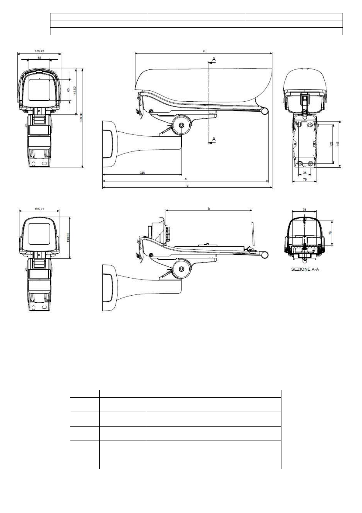
a (mm)
Senza
risca
ld
amento
c (mm)
d (mm)
532.34
Peso del
l
a custodia (
Kg)
Peso del tettu
ccio (Kg)
Peso del supporto e snodo (Kg)
Dimensioni utili
Internal dimensions
100 x 75 x 2
7
0 mm
Grado di protezione
Weatherproof rating
IP 66
Temper
a
tura di funzionamento
Operating temper
a
ture
-20°
C ÷ +
50°
C
b (mm)
520.61
270.00
430
2.79
0.89
1.10
With no heater
Weight of the housing (Kg)
Weight of the sunshield (Kg)
Weight of the bracket and swivel head (Kg)
Page 5
6
2
IT
LEGGERE ATTENTAMENTE TUTTE LE AVVERTENZE E LE ISTRUZIONI RIPORTATE NEL MANUALE, PRIMA DI
PROCEDERE ALL’INSTALLAZIONE DEL PRODOTTO
• TUTT
• QUESTO DOCUMENTO NON PUO’ ESSERE COPIATO IN PARTE, O ESSERE RIPRODOTTO, SENZA PREVIO CONSENSO SCRITTO DA
• IL PRODUTTORE NON SI ASSUME ALCUNA RESPONSABILITA’ PER LE CONSEGUENZE DERIVANTI DALL’USO IMPROPRIO DI QUESTO
• LE ISTRUZIONI DEVONO ESSERE CONSERVATE PER USO FUTURO
• LE INFORMAZIONI DI SEGUITO RIPORTATE POSSONO ESSERE SOGGETTE A CAMBIAMENTI SENZA PREAVVISO
CONTENUTI:
I I
DIRITTI RISERVATI.
PARTE DEL PRODUTTORE.
MANUALE
.
.
.
1. DATI TECNICI
2. AVVERTENZE
3.
FISSAGGIO DEL SUPPORTO ALLA PARETE
Pag: 1
Pag: 2
Pag: 7
4. INGRESSO DEI CAVI E FISSAGGIO DELLO SNODO AL SUPPORTO Pag: 8
5. APERTURA DELLA CUSTODIA
6. INGRESSO DEI CAVI
7. ASSEMBLAGGIO DELLA TELECAMERA
8. COLLEGAMENTI ELETTRICI
9.
10.
POSIZIONAMENTO E CHIUSURA DELLA CUSTODIA
SCHEMI DEI COLLEGAMENTI ELETTRICI
Pag: 9
Pag: 10
Pag: 11
Pag: 12
Pag: 12
Pag: 13
AVVERTENZE:
l’installazione e l’uso del prodotto deve essere eseguita da personale tecnico qualificato, nel rispetto delle
leggi previste nel luogo dove tale prodotto viene utilizzato.
Prima di iniziare qualsiasi operazione di installazione o di manutenzione, assicurarsi che siano stati azionati
tutti i dispositivi di sezionamento, (dei quali deve essere provvista la rete di alimentazione) con una distanza fra
i contatti di almeno 3 mm.
Se disattivata da poco tempo, la resistenza potrebbe conservare elevate temperature
Utilizzare solo parti di ricambio originali.
La custodia, se correttamente installata, non necessita di manutenzione.
Sul prodotto, o sul presente manuale, potreste trovare alcuni simboli di seguito riportati e spiegati:
PERICOLO
Si allerta l’utente della presenza di tensioni
pericolose per l’incolumità di persone e/o animali
domestici
ATTENZIONE
Si allerta l’utente della presenza di importanti
istruzioni, da leggere, comprendere e seguire
scrupolosamente, al fine di evitare il rischio di
danneggiamento del prodotto durante le
operazioni di installazione e/o manutenzione.
Page 6
1
3
EN
READ CAREFULLY ALL THE CAUTIONS AND INSTRUCTIONS IN THE MANUAL BEFORE INSTALLING THE
PRODUCT
•
ALL RIGHTS RESERVED.
•
THIS DOCUMENT MAY NOT BE COPIED IN WHOLE OR IN PART, OR OTHERWISE REPRODUCED WITHOUT THE PRIOR WRITTEN
CONSENT F.ROM THE MANUFACTURER.
•
THE MANUFACTURER DECLINES ANY LIABILITIES INCURRED AS A CONSEQUENCE, DIRECTLY OR INDIRECTLY, OF THE
IMPROPER USE OR APPLICATION OF ANY OF THE CONTENTS OF THIS MANUAL.
•
KEEP THIS MANUAL IN A SAFE PLACE FOR FUTURE REFERENCE.
•
THE INFORMATION GIVEN BELOW IS SUBJECT TO CHANGE WITHOUT NOTICE.
CONTENTS:
1. TECHNICAL DATA
2. CAUTIONS
3. MOUNTING THE BRACKET TO THE WALL
4. FITTING THE CABLE AND ATTACHING THE SWIVEL HEAD
TO THE BRACKET
5. OPENING THE HOUSING
6. FITTING THE CABLES
7. MOUNTING THE CAMERA
8. ELECTRICAL WIRING
9. CLOSING THE HOUSING
10. ELECTRICAL WIRING DIAGRAMS
CAUTIONS:
The product must only be installed and used by qualified technicians, in compliance with statutory regulations of the
place where the product is used.
Before beginning any installation or maintenance work shut-off all safety cut-outs on the mains power supply with a
contact breaker gap of at least 3 mm.
If the heating element has been shut off recently, it may still be hot
Only use genuine spare parts.
If properly installed, the housing is completely maintenance free.
On the product or in this manual you may find the symbols indicated and explained as follows:
DANGER
ATTENTION
The user is warned of the presence of
dangerous tensions for people and domestic
animals.
The user is warned of the presence of important
instructions to read, understand and follow
carefully in order to avoid the risk of improper
use that may result in damages to the product.
Pag: 1
Pag: 3
Pag: 7
Pag: 8
Pag: 9
Pag: 10
Pag: 11
Pag: 12
Pag: 12
Pag: 13
Page 7

6
Der B
e
nutzer wird dav
or gewa
rnt, dass
da eine
4
DE
LESEN SIE BITTE AUFMERKSAM DIE IM HANDBUCH GESCHRIEBENE GEBRAUCHSEINWEISUNG DURCH,
BEVOR SIE DIE MONTAGE DES PRODUKTS BEGINNEN
• ALLE RECHTE VORBEHALTEN.
• DIESES DOKUMENT KANN NICHT OHNE NACH VORHERIGER GESCHRIEBENER ZUSTIMMUNG DES HERSTELLERS, ALLES ODER
TEILWEISE, KOPIERT ODER REPRODUZIERT WERDEN.
• DER HERSTELLER NIMMT AUF SICH KEINE VERANTWORTUNG FÜR DIE FOLGEN, DIE AUS MISSBRÄUCHLICH VERWENDUNG
DIESES HANDBUCHS ENTSTEHEN SOLLTEN.
• DIE NACHSTEHEND ANGEFÜHRTEN INFORMATIONEN KÖNNEN OHNE VORANKÜNDIGUNG VERÄNDERT WERDEN.
• DIE GEBRAUCHSEINWEISUNG SOLL FÜR ZUKUNFTIG VERVENDUNG VERWAHRT WERDEN.
INHALTSVERZEICHNIS:
1. TECHNISCHEN ANGABEN
2. HINWEISE
3. BEFESTIGUNG DER SCHUTZGEHÄUSES AN DER HALTERUNG
4. KABELEINGANG UND BEFESTIGUNG DES GELENKS AN DER
HALTERUNG
5. ÖFFNEN DES GEHÄUSES
6. KABELEINGANG
7. MONTIEREN DER KAMERA
8. ELEKTRONASCLŮSSE
9. POSITIONIEREN UND SCHLIESSEN DES GEHÄUSES
10. SCHALTPLAN
Seite: 1
Seite: 4
Seite: 7
Seite: 8
Seite: 9
Seite: 10
Seite: 11
Seite: 12
Seite: 12
Seite: 13
HINWEISE:
Installation und Gebrauch des Produktes müssen durch qualifiziertes Fachpersonal und unter Befolgung der am
Installationsort geltenden Gesetzesvorschriften erfolgen.
Bevor irgendwelche Installations-oder Wartungsarbeiten ausgeführt werden, muss sichergestellt werden, dass
sämtliche Trennvorrichtungen (mit einem Abstand der Kontaktöffnung von mindestens 3 mm), mit denen das
Versorgungsnetz ausgestattet sein muss, ausgelöst wurden.
Falls der Widerstand erst seit kurzer Zeit deaktiviert ist, kann er noch sehr hohe Temperaturen haben.
Verwenden Sie ausschließlich Original-Ersatzteile.
Sofern das Gehäuse korrekt installiert wurde, erfordert es keinerlei Wartung.
Sie könnten die nachstehend dargestellten und erklärten Symbole auf dem Produkt oder in diesem Handbuch finden:
GEFAHR
Der Benutzer wird davor gewarnt, dass da
Spannungen sind, die für Menschen und/oder
Haustiere gefährlich sind.
ACHTUNG!
wichtige Gebrauchseinweisung ist, die gelesen,
und verstanden werden muss und an die man
sich streng halten muss, um das Produkt
während der Montage und/oder der
Wartungsarbeit nicht zu schaden.
Page 8

1
5
FR
LIRE AVEC ATTENTION TOUS LES AVERTISSEMENTS ET LES INSTRUCTIONS DANS LE MANUEL, AVANT DE
PROCÉDER A L’INSTALLATION DU PRODUIT
• TOUT DROIT RÉSERVÉ.
• CE DOCUMENT NE PEUT PAS ÊTRE COPIE, EN TOUT OU EN PARTIE, OU ÊTRE RÉPRODUIT, AVANT D’AVOIR OBTENU LE CONSENTEMENT
ÉCRIT DU PRODUCTEUR.
• LE PRODUCTEUR NE S'ASSUME AUCUNE RESPONSABILITÉ POUR TOUTE CONSEQUENCE QUI DÉRIVE D’UN USAGE INAPPROPRIÉ DE
CE MANUEL.
• LES INFORMATIONS DONNÉES CI-APRÈS PEUVENT SUBIR DES CHANGEMENTS SANS PRÉAVIS.
• LES INSTRUCTIONS DOIVENT ÊTRE CONSERVÊES POUR TOUT EMPLOI FUTURE.
CONTENUS:
1. DONNÉES TECHNIQUES
Page : 1
2. AVVERTISSEMENTS
Page : 5
3. FIXATION DU SUPPORT AU MUR
4. ENTRÉE CÂBLES ET FIXATION DE L’ARTICOLATION
AU SUPPORT
5. OUVERTURE DU CAISSON
Page: 7
Pa ge : 8
Page : 9
6. ENTRÉE DES CÂBLES
Page : 10
7. ASSEMBLAGE CAMÉRA
Page : 11
8. CONNEXIONS ÉLECTRIQUES
Page : 12
9. FERMETURE DU CAISSON
Page : 12
10. PLAN DES CONNEXIONS ÉLECTRIQUES
AVVERTISSEMENTS :
Le produit doit être installé et utilisé par du personnel technique qualifié, dans le respect des lois en vigueur dans le
lieu où le produit est utilisé.
Avant de commencer n’importe quelle opération d’installation ou d’entretien, s’assurer que tous les dispositifs de
déconnexion qui doivent être présents sur la ligne d’alimentation ont bien été actionnés (la distance d’ouverture entre
les contacts de ces dispositifs doit être d’au moins 3 mm).
Si la résistance a été désactivée depuis peu de temps, elle pourrait être encore à une température élevée.
N’utiliser que des pièces de rechange originales.
Le caisson, s’il est installé correctement, ne demande pas d’entretien.
Sur le produit, ou sur ce manuel, vous pourriez trouver certains symboles indiqués et expliqués ci-dessous:
DANGER
On alerte l’usager de la présence de tensions
dangereuses pour la sécurité de personnes et/ou
animaux domestiques
Page : 13
ATTENTION
On alerte l’usager de la présence d’instructions
importantes, à lire, comprendre, et suivre
scrupuleusement, au fin d’éviter le risque
d’endommagement du produit durant les
opérations d’installation et/ou entretien.
Page 9

6
6
ES
ANTES DE INSTALAR EL PRODUCTO, LEER ATENTAMENTE TODAS LAS ADVERTENCIAS E INSTRUCCIONES
• TODOS LOS DERECHOS RESERVADOS
• ESTE DOCUMENTO NO PUEDE SER COPIADO ENTERAMENTE O EN PARTE, O SER REPRODUCIDO, SIN EL PREVIO CONSENTIMIENTO
ESCRITO DEL FABRICANTE.
• EL FABRICANTE NO ASUME RESPONSABILIDAD ALGUNA POR LAS CONSECUENCIAS CAUSADAS POR UN USO IMPROPIO DE ESTE
MANUAL.
• GUARDAR ESTE MANUAL PARA FUTURAS CONSULTACIONES
• LAS INFORMACIONES INDICADAS A CONTINUACIÓN ESTÁN SUJETAS A MODIFICACIONES SIN AVISO PREVIO
.
CONTENIDAS EN EL MANUAL
.
.
CONTENUTI:
1. DATOS TECNICOS
2. ADVERTENCIAS
3. FIJACIÓN DEL SOPORTE EN LA PARED
4. ENTRADA DE LOS CABLES Y
FIJACIÓN DE LA ROTULA
EN EL SOPORTE
5. APERTURA DE LA CARCASA
6. ENTRADA DE LOS CABLES
7. ENSAMBLAJE DE LA CAMARA
8. CONEXIONES ELÉCTRICAS
9. CIERRE DE LA CARCASA
10. ESQUEMAS PARA LAS CONEXIONES ELÉCTRICAS
Pag: 1
Pag: 6
Pag: 7
Pag: 8
Pag: 9
Pag: 10
Pag: 11
Pag: 12
Pag: 12
Pag: 13
ADVERTENCIAS:
La instalación del producto y su manejo estarán a cargo de personal técnico cualificado, en observancia de las
leyes locales.
Antes de comenzar cualquier operación de instalación o mantenimiento, comprobar que se hayan accionado todos
los dispositivos de desconexión (con los que la red de alimentación estará provista), con una distancia de apertura
de los contactos de al menos 3 mm.
Si hace poco tiempo que se ha desactivado la resistencia, su temperatura podría ser todavía elevada.
Utilizar sólo piezas de recambio originales.
Si la carcasa está instalada correctamente no necesita mantenimiento.
Sobre el producto o en este manual se pueden encontrar los siguientes símbolos explicados en seguida:
PELIGRO
Se informa al usuario de la presencia de
tensiones peligrosas para la incolumidad de las
personas y/o de los animales domésticos .
ATTENCIÓN
Se informa al usuario de la presencia de
importantes instrucciones, a leer, comprender, y
a seguir escrupulosamente, para evitar el riesgo
de dañar el producto durante las operaciones de
instalación y/o manutención.
Page 10

1
7
FISSAGGIO DEL SUPPORTO ALLA PARETE
Tenere una riserva di cavo/i di almeno 70 cm dalla parete.
Porre il supporto nella posizione desiderata, contro la parete verticale.
Marcare la posizione dei fori di fissaggio.
Realizzare i fori di fissaggio tenendo conto del materiale costituente la parete e del tipo di tasselli di fissaggio che si andranno ad
utilizzare.
Passare i cavi attraverso il supporto e fissare saldamente il supporto alla parete.
Se i cavi sono applicati esternamente alla parete è possibile rimuovere uno dei fianchetti laterali al supporto per passare i cavi
all’interno del supporto.
MOUNTING THE BRACKET
There must be an adequate length of free cable (70 cm approx.) to run through the housing and make connections.
Place the mounting plate against the vertical mounting surface, ensure that it is level, and mark the location of the four mounting
holes.
Prepare the mounting holes appropriately according to the type of surface (concrete, wood, etc.) and fasteners used.
Feed the cables through the mounting bracket and attach the bracket to the mounting surface with appropriate fasteners.
If the cables are attached externally to the mounting surface, remove one of the slot covers on the mounting bracket to provide an
opening for the cable to enter.
BEFESTIGUNG DES SCHUTZGEHÄUSES AN DER HALTERUNG
Eine Kabelreserve von mindestens 70 cm von der Wand sicherstellen.
Die Halterung an der gewünschten Stelle, an die Wand setzen.
Die Position der Bohrlöcher markieren.
Nun je nach Beschaffenheit der Wand und der zu verwendenden Dübel die Bohrlöcher ausführen.
Die Kabel durch die Halterung führen und die Halterung sicher an der Wand befestigen.
Falls die Kabel außen an der Wand angebracht sind, kann eines der Seitenteile der Halterung abgenommen werden, damit
die Kabel durch das Innere der Halterung geführt werden können.
FIXATION DU SUPPORT AU MUR
Garder au moins 70 cm de réserve de câble par rapport au mur.
Placer le support dans la position désirée, contre le mur vertical.
Marquer la position des trous de fixation.
Percer les trous en tenant compte du matériau constituant le mur ou la cloison et du type de cheville qu’il faudra utiliser.
Passer les câbles à travers le support et fixer solidement celui-ci au mur.
Si les câbles ne proviennent pas de l’intérieur du mur, il est possible d’enlever l’un des petites trappes du support pour passer
les câbles à l’intérieur de ce dernier.
FIJACIÓN DEL SOPORTE EN LA PARED
Dejar que salgan de la pared trozos de cables de al menos 70 cm.
Situar el soporte en la posición deseada, contra la pared.
Marcar la posición de los agujeros de fijación.
Taladrar los agujeros de fijación teniendo en cuenta tanto el material con que está construida la pared como el tipo de
tornillos de expansión a utilizar.
Pasar los cables por el soporte y fijarlo firmemente a la pared.
De instalar los cables en la parte exterior de la pared, es posible desmontar uno de los laterales del soporte y pasar los cables por
su interior.
Page 11

6
INGRESSO CAVI E FISSAGGIO DELLO SNODO AL SUPPORTO
8
Lasciare, per ora, chiusa la custodia ma svitare le due viti di fissaggio tra custodia e snodo.
Tenendo lo snodo nella posizione della figura, passare i cavi attraverso lo snodo.
Posizionare e, tramite la vite in dotazione, fissare lo snodo al supporto.
Effettuare un posizionamento di massima della custodia, fissando temporaneamente le viti dello snodo.
Alzare ora la custodia e, a seconda dei cavi che si stanno utilizzando, perforare i pressacavi e passare attraverso di essi i cavi.
FITTING THE CABLES AND ATTACHING THE SWIVEL HEAD TO THE BRACKET
Keep the housing closed and loosen the two screws that fix the swivel head to the housing itself.
Feed the cables through the swivel head, keeping the housing as shown in the figure below.
Line the base of the swivel head up over the cable opening and tighten the attachment screw into the swivel head.
Fix the housing in the approx. intended position by tightening the screws of the swivel head.
Open the housing and, according to the number and size of the cables to be used, perforate the cable glands and feed the cables
through them.
KABELEINGANG UND BEFESTIGUNG DES GELENKS AN DER HALTERUNG
Bei geschlossenem Gehäuse die beiden Befestigungsschrauben zwischen Gehäuse und Gelenk aufschrauben.
Das Gelenk in der abgebildeten Position halten und die Kabel durch das Gelenk führen.
Das Gelenk ausrichten und mit Hilfe der mitgelieferten Schraube an der Halterung befestigen.
Das Gehäuse ungefähr ausrichten, indem die Schrauben des Gelenks vorläufig festgezogen werden.
Nun das Gehäuse anheben und je nach Zahl der verwendeten Kabel die Kabelschellen anbohren und die Kabel durch sie
hindurchführen.
ENTRÉE CÂBLES ET FIXATION DE L’ARTICULATION AU SUPPORT
Avec le caisson fermé, dévisser les deux vis de fixation entre le caisson et l’articulation.
En gardant l’articulation dans la position de la figure, passer les câbles à travers l’articulation.
Positionner l’articulation sur le support et l’y fixer avec la vis fournie.
Effectuer un positionnement approximatif du caisson, en fixant de manière temporaire les vis de l’articulation
Soulever maintenant le caisson et suivant le nombre de câbles que l’on doit utiliser, percer les passe-câbles et y faire passer
les câbles.
ENTRADA DE LOS CABLES Y FIJACIÓN DE LA ROTULA EN EL SOPORTE
Manteniendo la carcasa cerrada, soltar los dos tornillos de fijación entre la carcasa y la rotula.
Situar la rotula como en la figura y pasar los cables a través de ella.
Colocar y fijar la rotula en el soporte, con el tornillo suministrado.
Colocar temporalmente la carcasa, fijándo los tornillos de la rotula.
Levantar ahora la carcasa y, conforme a la cantidad de cables que se están utilizando, perforar los prensaestopas y pasar los
cables a través de ellos.
Page 12

1
9
APERTURA DELLA CUSTODIA
Aprire la chiusura a leva e, ruotando la parte superiore della chiusura, liberare il coperchio dalla base , permettendo così l’apertura
della custodia.
ATTENZIONE: pericolo di scossa elettrica. Assicurarsi di aver
azionato tutti i dispositivi di sezionamento.
Sollevare il coperchio e dopo aver scollegato il cavo di messa a terra, facendo perno sulla vite anteriore, ruotare il coperchio per
aprire completamente la custodia.
OPENING THE HOUSING
Release the latch, swing the lid up from the base to open the housing.
WARNING: danger of electric shock. Make sure that all safety
-
cut
outs on the main power suppl
Lift the lid and disconnect the earthing cable, then swing the lid over its front screw to fully open the housing.
ÖFFNEN DES GEHÄUSES
Den Bügelverschluss öffnen und den Deckel von der Basis befreien, indem der obere Teil des Verschlusses hochgeklappt wird, so
dass das Gehäuse geöffnet werden kann.
ACHTUNG!: elektrischer Schlag-Gefahr. Versichern Sie
sich, dass Sie alle Leitungsunterteilungen betrieben
haben.
Den Deckel anheben, das Erdkabel abtrennen, an der vorderen Schraube ansetzen und den Deckel hochklappen, so dass das
Gehäuse ganz geöffnet werden kann.
OUVERTURE DU CAISSON
Ouvrir la fermeture à levier et libérer le couvercle de la base pour pouvoir ainsi ouvrir le caisson.
ATTENTION: danger de décharge électrique. Assurezvous d’avoir activé tous les dispositifs de sectionnement.
Soulever le couvercle et après avoir déconnecté le câble de mise à la terre en faisant pivot sur la vis frontale, rabattre le couvercle
pour ouvrir complètement le caisson.
APERTURA DE LA CARCASA
Desenganchar el cierre y soltar la tapa para poder abrir la carcasa.
ATENCIÓN: peligro de choque eléctrico.
Asegurarse de accionar todos los dispositivos de
seccionamiento
Levantar la tapa y desconectar el cable de puesta a tierra, luego, abrir la carcasa completamente.
are shutt
y
Nota: se si adotta il kit di sicurezza con vite torx (fornito come
accessorio), smontare preventivamente il suddetto kit per mezzo
della chiave in dotazione.
-
off.
Note: when using the security kit with Torx screws, first remove
the kit using the spanner provided.
NB: wenn das Sicherheits-Kit mit Torx-Schraube
verwendet wird, muss dieses zuvor mit dem mitgelieferten
Schlüssel ausgebaut werden.
Note: Si l’on opte pour le kit de sûreté avec vis Torx,
démonter au préalable le kit en question avec la clé
fournie.
Nota: si se adopta el kit de seguridad con tornillo Torx,
hay que desmontar previamente el citado kit utilizando la
llave en equipamiento.
Page 13

6
10
INGRESSO CAVI
Recuperare la riserva di cavo verso l’interno della custodia evitando di tirare eccessivamente, per non impedire futuri movimenti
dello snodo in fase di puntamento dell’area da sorvegliare.
Fissare le viti di chiusura dei pressacavi.
Nota: per facilitare l’ingresso dei cavi, sollevare e far
ruotare indietro il supporto per accessori.
CABLE ENTRY
Pull the cables inside the housing leaving enough slack to allow for adjustments in the position of the housing.
Tighten the two screws of the cable glands.
Note: to make it easier to feed the cables, lift and swing
backward the accessory holder.
KABELEINGANG
Die Kabel in das Innere des Gehäuses ziehen, wobei sie im Innern des Gelenks nicht zu stark gespannt sein dürfen, damit bei
der endgültigen Positionierung des Gehäuses die Bewegungen des Gelenks nicht behindert werden.
Die Verschlussschrauben der Kabelschellen befestigen.
NB: Um den Eintritt der Kabel zu erleichtern, die Halterung
der Zuberhörteile anheben und verschieben.
ENTRÉE CÂBLES
Tirer les câbles vers l’intérieur du caisson en faisant en sorte qu’ils ne soient pas trop tendus à l’intérieur de l’articulation; cela
pour éviter que les mouvements de l’articulation puissent être en quelque sorte entravés quand on devra effectuer
le positionnement final du caisson.
Fixer les vis de fermeture des passe-câbles.
Note: pour faciliter l’entrée des câbles, soulever et
tourner le support pour accessoires
ENTRADA DE LOS CABLES
Tirar de los cables hacia el interior de la carcasa pero sin tensarlos demasiado dentro de la rotula, para que ésta se pueda
mover sin impedimentos al posicionar la carcasa definitivamente.
Fijar los tornillos de cierre de los prensaestopas.
Nota: para facilitar la entrada de los cables, levantar y
girar el porta-accesorios.
Page 14

1
11
ASSEMBLAGGIO DELLA TELECAMERA
In funzione della dimensione della telecamera da installare, assemblare la slitta interna nella configurazione desiderata seguendo
lo schema sotto riportato.
Fissare la telecamera per mezzo della vite da 1/4”
Posizionare e fissare l’assieme telecamera più slitta, facendo attenzione che l’obbiettivo non superi la tacca “LENS” per non
interferire con il vetro in fase di chiusura della custodia.
MOUNTING THE CAMERA
The sled position depends on the camera size, select one of the configurations shown in the diagram below.
Attach the camera using the 1/4” screw.
Position and mount the camera and sled assembly, making sure that the lens does not pass the “LENS” mark, so it does not hit
the glass when closing the housing.
MONTIEREN DER KAMERA
Je nach Größe der zu installierenden Kamera die innere Montageschiene gemäß der gewünschten Konfiguration unter
Zuhilfenahme des Schemas hier unten anbringen.
Die Kamera mit Hilfe der 1/4” Schraube befestigen.
Die Kamera und die Montagschiene so ausrichten, dass das Objektiv nicht über die Kerbe “LENS” hinausgeht, damit beim
Schließen des Gehäuses keine Interferenzen mit dem Glas entstehen.
ASSEMBLAGE CAMÉRA
En fonction de la dimension de la caméra à installer, assembler la glissière interne dans la configuration désirée en suivant le
schéma ci-dessous.
Fixer la caméra avec la vis d’1/4”.
Positionner et fixer le groupe caméra plus glissière, en faisant attention que l’objectif ne dépasse pas l’encoche “LENS” pour éviter
toute interférence avec le verre en phase de fermeture du caisson.
ENSAMBLAJE DE LA CÁMARA
Según el tamaño de la cámara a montar, ensamblar el patín interior con la configuración deseada siguiendo el esquema de
abajo.
Fijar la cámara con el tornillo de 1/4”.
Posicionar y fijar el conjunto cámara más patín, teniendo cuidado de que el objetivo no sobrepase la marca “LENS” y no interfiera
con el cristal al cerrar la carcasa.
H O U S IN G C A P A C ITY WxH (mm-Inch)
LEVEL -1 75x81 - 2.95x3.18
LEVEL 0 76x76 - 2.99x2.99
LEVEL +1 81x67 - 3.18x2.63
LEVEL +2 81x62 - 3.18x2.44
Page 15

6
12
COLLEGAMENTI ELETTRICI
Effettuare i collegamenti elettrici secondo lo schema di pag. 13
ELECTRICAL WIRING
Make cable connections according to the electrical wiring diagrams provided on page 13
ELKEKTROANSCHLÜSSE
Die Elektroanschlüsse gemäss Schaltplan auf Seite 13 herstellen.
CONNEXIONS ÉLECTRIQUES
Effectuer les connexions électriques selon le schéma de la page 13.
CONEXIONES ELÉCTRICAS
Realizar las conexiones eléctricas con arreglo al esquema de la pág. 13.
POSIZIONAMENTO E CHIUSURA DELLA CUSTODIA
Posizionare definitivamente la custodia e fissare tutte le viti dello snodo.
Verificare posizionamento e pulizia della guarnizione.
Se mosso in precedenza, ruotare il supporto per accessori , riportandolo nella posizione iniziale.
Far ruotare il coperchio in modo opposto rispetto all’apertura.
Collegare il cavetto di messa a terra precedentemente scollegato dal coperchio.
Completare la rotazione del coperchio e per mezzo della chiusura a leva chiudere la custodia facendo attenzione a non pizzicare
qualche cavo di collegamento tra coperchio e guarnizione.
CLOSING THE HOUSING AND FIXING ITS POSITION
Place the housing in the desired position and tighten all the screws of the swivel head.
Check the gasket is clean and in position.
If the accessory holder was moved, turn it back to its original position.
Swing the lid back towards its original place.
Connect the earthing cable that was disconnected earlier from the lid.
Close the lid completely and lock the housing shut by the latch, making sure that no cables are being pinched between the lid and
gasket.
POSITIONIEREN UND SCHLIEßEN DES GEHÄUSES
Das Gehäuse definitiv positionieren und alle Schrauben des Gelenks festziehen.
Die Position und den Reinigungszustand der Dichtung kontrollieren.
Falls die Zubehörhalterung zuvor verstellt wurde, muss sie wieder in ihre ursprüngliche Position gebracht werden.
Den Deckel nach unten klappen.
Den zuvor vom Deckel getrennten Erddraht anschließen.
Den Deckel zuklappen und das Gehäuse mit Hilfe des Bügelverschluss verschließen, dabei darauf achten, dass zwischen Deckel
und Dichtung keine Kabel eingeklemmt werden.
POSITIONNEMENT ET FERMETURE DU CAISSON
Positionner définitivement le caisson et fixer toutes les vis de l’articulation.
Vérifier que la garniture est bien positionnée et propre.
S’il a été préalablement bougé, tourner le support pour accessoires en le remettant dans la position initiale.
Rabattre le couvercle dans le sens contraire par rapport à l’ouverture.
Connecter le câble de mise à la terre précédemment déconnecté du couvercle.
Compléter la rotation du couvercle et au moyen de la fermeture à levier, fermer le caisson en veillant à ne coincer aucun câble de
connexion entre le couvercle et le joint.
POSICIONAMIENTO Y CIERRE DE LA CARCASA
Colocar la carcasa en la posición elegida y apretar todos los tornillos de la rotula.
Verificar que la junta esté bien colocada y limpia.
De haber desplazado antes el porta-accesorios, girarlo hasta su posición original.
Levantar la tapa hasta casi cerrar la carcasa.
Conectar el cable de puesta a tierra desconectado antes de la tapa.
Completar la rotación de la tapa y, por medio del gancho, cerrar la carcasa teniendo cuidado de no apretar ningún cable de
conexión entre la tapa y la junta.
Page 16

1
L
N
N
L
L
N
L
N
COLLEGAMENTI ELETTRICI
RISCALDAMENTO
VENTILAZ
I
ONE
ALIMENTAT
ORE
Art. 4412
2 Art. 44120
Art. 44121
Art. 44194
Art. 44195
INPUT
24
VAC
100
-
240
VAC 230
VAC 24 V
AC 230
VAC 230
VAC
P
35
W 40
W 1 W 1W 5 W 10
W
I
400
mA
400
mA
OUTPUT
INPUT
230
VAC (art. 44120)
13
WIRING DIAGRAM
BELEGUNGS-SCHEMA
BRANCHEMENTS ELECTRIQUES
CONEXIONES ELECTRICAS
CON ALIMENTATORE (accessorio)
WITH POWER SUPPLY UNIT (optional)
INPUT 230 VAC (art. 44120)
OUTPUT 24 VAC (art. 44195) or 12
VDC (art. 44194)
SENZA ALIMENTATORE
WITHOUT POWER SUPPLY
INPUT 24 VAC (art. 44122)
UNIT
HEATER
HEIZUNG
CHAUFFAGE
CALEFACTOR
Art.44194/
Art. 44195
HEATER
230 VAC
FAN BOARD
230 VAC
HEA
TER
FAN
OUTPUT
L N
INPUT
-
PS
+
IN
PS
OUT
CAMERA
12 VDC or
24 VAC
-
+
INPUT
230 VAC (art. 44120)
HEATER
230 VAC or
24 VAC
FAN BOARD
230 VAC or
24 VAC
CAMERA
230 VAC or
24 VAC
BLOWER
LÜFTERSET
VENTILATION
VENTILADOR
HEA
L
TER
N
N
FAN
L
OUTPUT
L N
INPUT
INPUT
230 VAC (art. 44120) or
24 VAC (art. 44122)
-
PS
+
IN
-
PS
+
OUT
POWER SUPPLY UNIT
STROMVERSORGUNG
ALIMENTATIO
ALIMENTACIÓ
N
N
12 VDC
24 VAC
Page 17

Via Don Arrigoni, 5 24020 Rovetta S. Lorenzo (Bergamo)
http://www.comelitgroup.com e-mail: commerciale.italia@comelit.it
export.department@comelit.it
 Loading...