

Page 1
EN
TECHNICAL
MANUAL
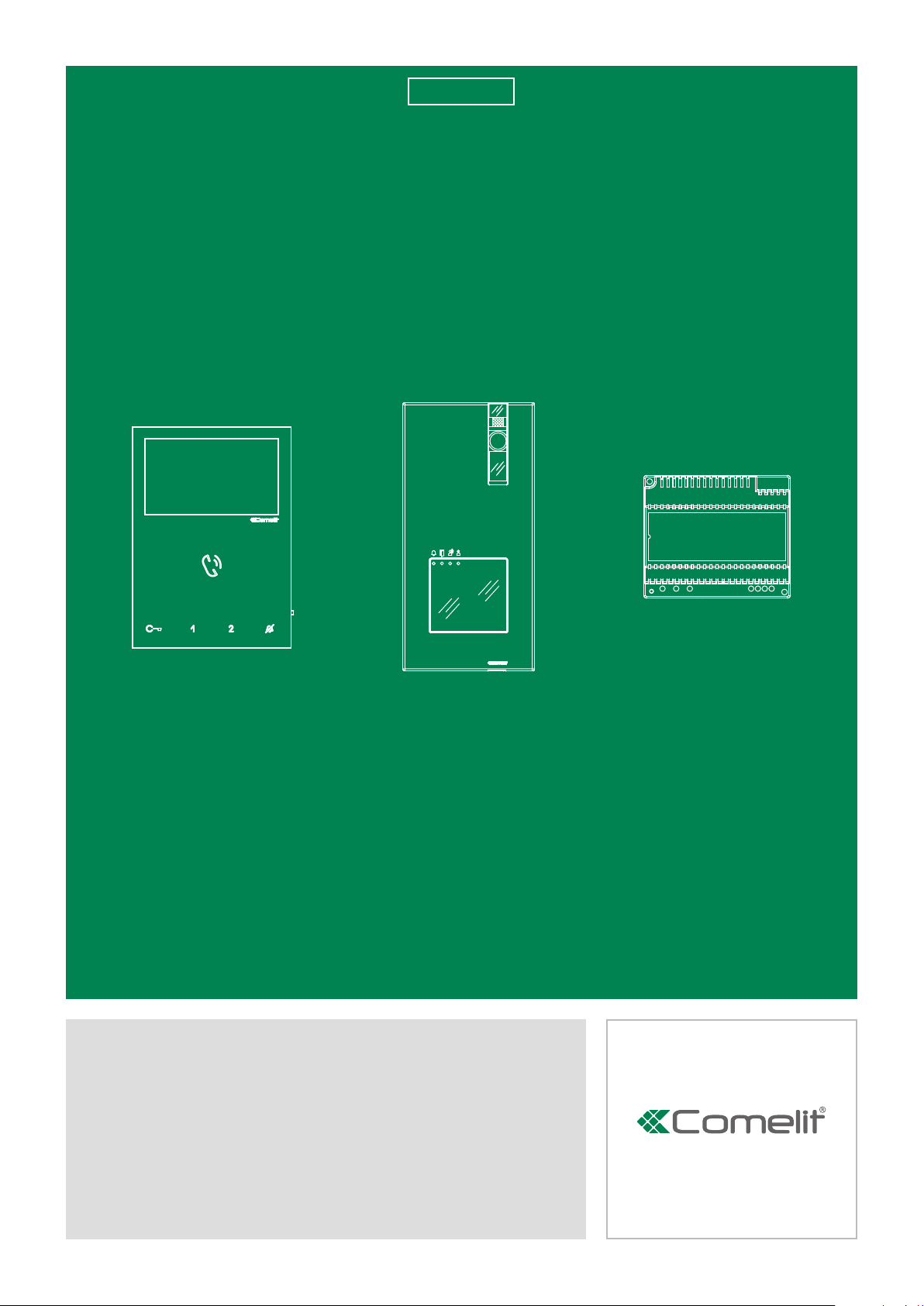
Single-family KIT
art. 8461V
Passion.Technology.Design.
Page 2

Warning
• Install the equipment by carefully following the instructions given by the manufacturer and in compliance with the
standards in force. Do not tamper with the internal elements offering protection against short circuits and overcurrents.
• All the equipment must only be used for the purpose it was designed for. Comelit Group S.p.A. declines any
responsibility for improper use of the apparatus, for any alterations made by others for any reason or for the use of
non-original accessories or materials.
• All the products comply with the requirements of the 2014/30/UE, 2014/35/UE directives, as certified by the CE mark
they carry.
• Do not route the riser wires in proximity to power supply cables (230/400V).
• Do not insert objects or pour liquids into the device.
• Installation, mounting and assistance procedures for electrical devices must only be performed by specialised
electricians.
• Cut off the power supply before carrying out any maintenance work.
• The camera must not be installed opposite bright light sources, or in places where the filmed subject is against the
light. To resolve the aforementioned problem, we recommend changing the installation height of the camera.
• Cameras with colour sensor have poorer sensitivity in low light conditions than black/white cameras. We therefore
recommend, in dimly lit environments, to install an additional light source.
• IMPORTANT: to prevent a malfunction of the device, make sure that the metal fascia of Art. 4893 does not rub against
any other metal parts and damage their insulation.
2
Page 3

Table of contents
Warning ............................................................................................ 2
Package Contents ........................................................................... 4
Operating distances ........................................................................ 5
Power supply unit Art. 1209 ............................................................ 6
Description ...............................................................................................6
External unit Art. 4893 ..................................................................... 7
Description ...............................................................................................7
Installation ................................................................................................8
External unit settings .............................................................................10
Call address programming for 2-4 users
and additional external unit ...................................................................11
Programming a generic call address ...................................................12
Riser addresses ......................................................................................13
Description of Monitor Art. 6721W .............................................. 14
Soft-touch key description ....................................................................15
Indicator LED description......................................................................15
Installation ...................................................................................... 16
Removing / Fitting the terminal ............................................................17
Fitting upgrade KIT Art. 6734W .............................................................17
Operation ........................................................................................ 18
Answer incoming call.............................................................................18
Activation/deactivation automatic answer mode ...............................18
Monitor configuration ................................................................... 18
Standard configuration for soft-touch keys ........................................18
Advanced monitor configuration ..........................................................19
Warning .............................................................................................19
Programming for intercom call ..........................................................19
Programming/deleting intercom address .................................. 19
Programming buttons for intercom call ..................................... 20
Direct programming of intercom call .........................................21
Programming keys for generic or coded actuator ............................22
Programming buttons for other functions .........................................23
Programming range ..........................................................................24
Monitor ringtone selection ................................................................24
Programming reset ...........................................................................25
Operation ........................................................................................ 26
To make a call from an external unit ....................................................26
Self-ignition .............................................................................................26
Operation with additional internal units ...............................................26
Operation with additional external units ..............................................26
Additional door-entry phones Art. 2638 ...................................... 27
Installation of door-entry phone Art. 2638 ...........................................28
Programming of door-entry phone Art. 2638.......................................28
Wiring diagrams............................................................................. 29
KIT 8461V: standard single-family system.
Switching on/voltage check with system in standby .........................29
KIT 8461V: expansion for two-family system ......................................30
KIT 8461V: expansion for 4-user system..............................................31
KIT 8461V: expansion with second external unit 4893
and switching device Art. 1405 .............................................................32
KIT 8461V: expansion with 3 external units 4893
and switching device Art. 1404 .............................................................33
Wiring diagram for system with 2 single-family KITS KIT 8461V
and main external unit Art. 4893 ...........................................................34
KIT 8461V: additional actuator relay Art. 1256 ....................................35
KIT 8461V: additional remote camera module Art. 1409 ....................36
KIT 8461V: additional 2 secondary monitors
in cascade connection ...........................................................................37
Connection diagram for two-family system with one main monitor
and 2 secondary monitors (cascade connection) ...............................37
Connection diagram for system with maximum expansion
in branch connection for single call address ......................................38
Connection diagram for cascade connection
from internal video unit of additional door-entry phones
Art. 2610 and Art. 6228(B)(W) ................................................................38
Connection diagram for branch connection
from internal video unit of additional door-entry phones
Art. 2610 and Art. 6228(B)(W) ................................................................38
Connection diagram for branch connection from riser of additional
door-entry phones Art. 2738W and Art. 6228(B)(W) ............................39
Door open indication use variant..........................................................39
Variant with security door lock and additional power supply ............40
Floor door call connection variant........................................................40
Using the RC network for door lock filter on relay contacts .............40
3
Page 4
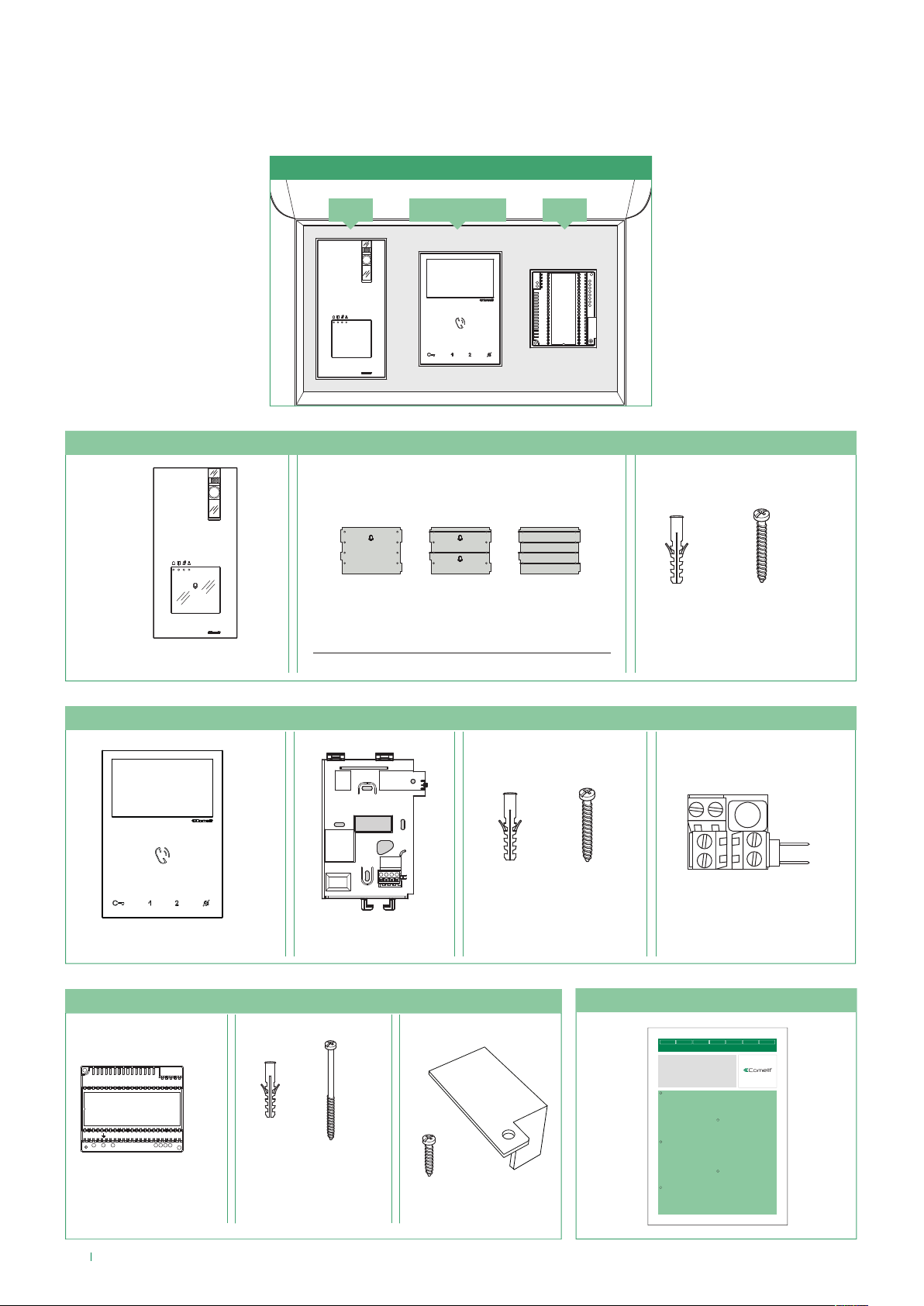
Package Contents
The KIT components are supplied preconfi gured for use with the basic version; this manual also includes information for any
system confi guration and customisation perceived as necessary by the installer.
8461V (/BM)
6721W(/BM) 12094893
4893 External unit
×1
Replaceable nameplates
for 1 user
6721W(/BM) - Monitor
×1 ×1
1209 - Power supply unit
×1 ×1 ×1 ×3 ×3
for 2 users for 3 users
×4
×4
1214-2C
Technical manual
×1
IT
EN
FR
NL
DE
ES
MANUALE
TECHNICAL
MANUEL
TECNICO
Manuale tecnico KIT monofamiliare Art. 8461V
Technical manual for single-family KIT Art. 8461V
Manuel technique KIT un appel Art. 8461V
Technische handleiding enkelvoudige installatieKIT Art. 8461V
Technisches Handbuch KIT Einteilnehmerinstallation Art. 8461V
Manual técnico del KIT unifamiliar Art. 8461V
×2
×2
×1
L2L L1N
×1
Manual técnico KIT monofamiliar Art. 8461V
Avvertenze
IT
• Effettuare l’installazione seguendo scrupolosamente le istruzioni fornite dal
costruttore ed in conformità alle norme vigenti. Non manomettere le protezioni
interne contro cortocircuiti e sovracorrenti.
• Tutti gli apparecchi devono essere destinati esclusivamente all’uso per cui sono
stati concepiti. Comelit Group S.p.A. declina ogni responsabilità per un utilizzo
improprio degli apparecchi, per modifiche effettuate da altri a qualunque titolo e
scopo, per l’uso di accessori e materiali non originali.
• Tutti i prodotti sono conformi alle prescrizioni delle direttive 2014/30/UE, 2014/35/
UE e ciò è attestato dalla presenza della marcatura CE sugli stessi.
• Evitare di porre i fili di montante in prossimità di cavi di alimentazione (230/400V).
• Non inserire oggetti né versare liquidi all’interno del dispositivo.
• Gli interventi di installazione, montaggio e assistenza agli apparecchi elettrici
devono essere eseguiti esclusivamente da elettricisti specializzati.
• Togliere l’alimentazione prima di effettuare qualsiasi manutenzione.
• La telecamera non deve essere installata di fronte a grandi sorgenti luminose,
oppure in luoghi dove il soggetto ripreso rimanga molto in controluce. Per risolvere
il problema precedentemente descritto, si consiglia di modificare l’altezza di
installazione della telecamera.
• Le telecamere con sensore a colori, presentano in condizioni di scarsa luminosità,
una sensibilità inferiore rispetto alle telecamere in bianco e nero. Si consiglia
pertanto, in ambienti poco illuminati di prevedere una fonte di illuminazione
aggiuntiva.
• IMPORTANTE: per non compromettere il funzionamento del dispositivo assicurarsi
che il frontale in metallo dell'articolo 4893 non sfreghi su altre parti metalliche
danneggiando il proprio rivestimento isolante.
Warning
EN
• Install the equipment by carefully following the instructions given by the
manufacturer and in compliance with the standards in force. Do not tamper with
the internal elements offering protection against short circuits and overcurrents.
• All the equipment must only be used for the purpose it was designed for. Comelit
Group S.p.A. declines any responsibility for improper use of the apparatus,
for any alterations made by others for any reason or for the use of non-original
accessories or materials.
• All the products comply with the requirements of the 2014/30/UE, 2014/35/UE
directives, as certified by the CE mark they carry.
• Do not route the riser wires in proximity to power supply cables (230/400V).
• Do not insert objects or pour liquids into the device.
• Installation, mounting and assistance procedures for electrical devices must only
be performed by specialised electricians.
• Cut off the power supply before carrying out any maintenance work.
• The camera must not be installed opposite bright light sources, or in places where
the filmed subject is against the light. To resolve the aforementioned problem, we
recommend changing the installation height of the camera.
• Cameras with colour sensor have poorer sensitivity in low light conditions than
black/white cameras. We therefore recommend, in dimly lit environments, to install
an additional light source.
• IMPORTANT: to prevent a malfunction of the device, make sure that the metal
fascia of Art. 4893 does not rub against any other metal parts and damage their
insulation.
Avertissements
FR
• Effectuer l'installation en suivant scrupuleusement les instructions fournies par
le constructeur et conformément aux normes en vigueur. Ne pas toucher les
protections internes contre les courts-circuits et les surcharges.
• Tous les appareils doivent être strictement destinés à l'emploi pour lequel ils ont
été conçus. La société Comelit Group S.p.A. décline toute responsabilité en cas
de mauvais usage des appareils, pour des modifications effectuées par d’autres
personnes pour n’importe quelle raison et pour l'utilisation d’accessoires et
matériaux non d'origine.
• Tous les produits sont conformes aux prescriptions des directives 2014/30/UE,
2014/35/UE. L'application du marquage CE atteste cette conformité.
• Éviter de placer les fils de montant à proximité des câbles d'alimentation
(230/400V).
• Ne jamais introduire d'objets ni verser de liquides à l'intérieur du dispositif.
• Les interventions d'installation, de montage et d'assistance aux appareils
TECHNISCHE
MANUAL
TECHNIQUE
HANDLEIDING
NL
DE
TECHNISCHES
MANUAL
HANDBUCH
TÉCNICO
Passion.Technology.Design.
électriques sont réservées à des électriciens spécialisés.
• Couper l'alimentation avant d'effectuer toute opération d'entretien.
• Installeer de camera niet tegenover felle lichtbronnen of op plaatsen waar de
opgenomen persoon met de rug naar het licht staat. Om het hierboven beschreven
probleem op te lossen, is het raadzaam de installatiehoogte van de camera aan
te passen.
• Camera's met kleurensensor hebben in schaars verlichte omstandigheden een
lagere gevoeligheid dan zwart-witcamera's. Het is daarom raadzaam om in
schaars verlichte omgevingen een extra lichtbron te plaatsen.
• IMPORTANT : pour ne pas compromettre le fonctionnement du dispositif,
s'assurer que la façade en métal de l'article 4893 n'entre pas en contact avec
d'autres parties métalliques, ce qui risquerait d'endommager son revêtement
isolant.
Waarschuwingen
• Voer de installatiewerkzaamheden zorgvuldig uit volgens de door de fabrikant
geleverde instructies en met inachtneming van de geldende normen. De interne
beveiligingen tegen kortsluiting en overstroom niet forceren.
• Alle apparaten mogen alleen gebruikt worden voor het beoogde doel waarvoor
ze zijn ontworpen. Comelit Group S.p.A. is niet verantwoordelijk voor oneigenlijk
gebruik van de apparatuur, voor wijzigingen die om welke reden dan ook door
derden zijn aangebracht, en voor het gebruik van accessoires en materialen die
niet door de fabrikant zijn aangeleverd.
• Alle producten voldoen aan de eisen van de richtlijn 2014/30/UE, 2014/35/UE. Dit
wordt bevestigd door het CE-label op de producten.
• Monteer de draden van de stamleiding niet in de buurt van voedingskabels
(230/400V).
• Voorkom het binnendringen van vreemde voorwerpen of vloeistoffen in het toestel.
• De installatie-, montage- en servicewerkzaamheden aan de elektrische apparaten
mogen uitsluitend door gespecialiseerde elektriciens worden verricht.
• Sluit de voeding af voordat u onderhoudswerkzaamheden uitvoert.
• Installeer de camera niet tegenover felle lichtbronnen of op plaatsen waar de
opgenomen persoon met de rug naar het licht staat. Om het hierboven beschreven
probleem op te lossen, is het raadzaam de installatiehoogte van de camera aan
te passen.
• Camera's met kleurensensor hebben in schaars verlichte omstandigheden een
lagere gevoeligheid dan zwart-witcamera's. Het is daarom raadzaam om in
schaars verlichte omgevingen een extra lichtbron te plaatsen.
• BELANGRIJK: om de werking van het toestel niet in gevaar te brengen, dient
u ervoor te zorgen dat het metalen frontpaneel, Art. 4893, niet over de andere
metalen onderdelen schuurt en daarmee de isolerende bekleding beschadigt.
Hinweise
• Der Einbau muss strikt nach Herstelleranweisungen und unter Einhaltung
der einschlägigen Vorschriften erfolgen. Nicht den internen Kurzschluss- und
Überlastungsschutz verändern.
• Alle Geräte dürfen nur für den Zweck eingesetzt werden, für den sie entwickelt
worden sind. Comelit Group S.p.A. übernimmt keine Haftung für unsachgemäßen
Gebrauch der Geräte, für durch Dritte vorgenommene Änderungen oder die
Verwendung von Nicht-Original-Zubehör und -Ersatzteilen.
• Alle unsere Produkte erfüllen die Anforderungen der Richtlinie 2014/30/UE,
2014/35/UE, was durch die CE-Kennzeichnung bestätigt wird.
• Die Kabel der Steigleitung nicht in Nähe der Stromkabel (230/400 V) verlegen.
• Keine spitzen Gegenstände in das Gerät einführen und dieses gegen das
Eindringen von Flüssigkeiten schützen.
• Installation, Einbau und Wartung der elektrischen Geräte dürfen nur von einem
Elektrofachmann ausgeführt werden.
• Vor Wartungseingriffen immer die Stromversorgung unterbrechen.
• Die Kamera darf nicht vor großen Lichtquellen oder an Stellen installiert werden,
an denen das Motiv zu sehr im Gegenlicht steht. Zur Lösung des Problems ist es
angebracht, die Installationshöhe der Kamera zu ändern.
• Die Kameras mit Farbsensor haben bei schlechten Lichtverhältnissen eine
geringere Empfindlichkeit als Schwarz/Weiß-Kameras. In schlecht beleuchteter
Umgebung wird daher empfohlen, für eine zusätzliche Lichtquelle zu sorgen
• WICHTIG: Um die Funktionsweise des Gerätes nicht zu beeinträchtigen,
sicherstellen, dass die Metallfrontblende des Artikels 4893 nicht gegen andere
Metallteile reibt und dadurch die eigene Isolierung beschädigt.
PT
MANUAL
TÉCNICO
4
Page 5
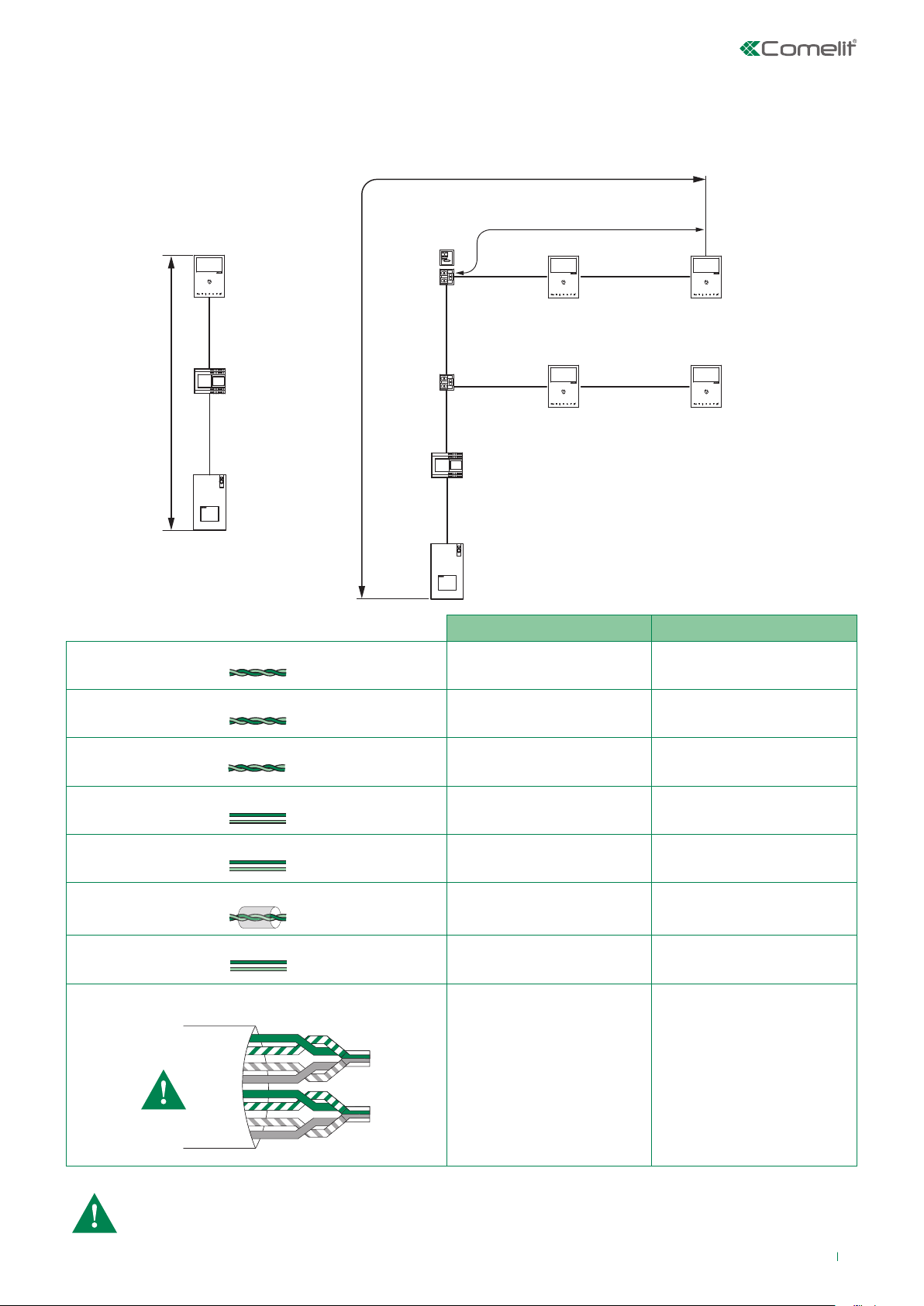
Operating distances
GREEN
ORANGE
BLU
GREEN / WHITE
ORANGE / WHITE
BLU / WHITE
BROWN / WHITE
BROWN
A
6721W
6721W
The total number of internal units with the same user code and call repetition devices (additional ringtone Art. 1229A)
connected to these internal units cannot exceed 4 (with a maximum of 1 main internal unit and 3 secondary internal units).
Connect only one call repetition device for each internal unit.
B
6721W
1209
1216
1214/2C
1214/2C
A
1209
4893
4893
A MAX B MAX
Comelit Art. 4577/4579 1 mm2 (Ø 1,2 mm AWG 17) 200 m
(655 feet)
UTP5 cat. 5 0,2 mm2 (Ø 0,5 mm AWG 24) 100 m
(330 feet)
100 m
(330 feet)
60 m
(195 feet)
0,28 mm2 (Ø 0,6 mm AWG 23)
0,5 mm2 (Ø 0,8 mm AWG 20)
1 mm2 (Ø 1,2 mm AWG 17)
1 mm2 (Ø 1,2 mm AWG 17)
1,5 mm2 (Ø 1,4 mm AWG 15)
100 m
(330 feet)
100 m
(330 feet)
100 m
(330 feet)
80 m
(260 feet)
100 m
(330 feet)
60 m
(195 feet)
60 m
(195 feet)
60 m
(195 feet)
40 m
(130 feet)
60 m
(195 feet)
*UTP5 cat. 5 0,2 mm2 (Ø 0,5 mm AWG 24)
MULTI PAIR CABLE
200 m
(660 feet)
70 m
(230 feet)
UTP cable with multi-cable connection: FOLLOW THE COLOURS SHOWN IN THE DIAGRAM!
5
Page 6
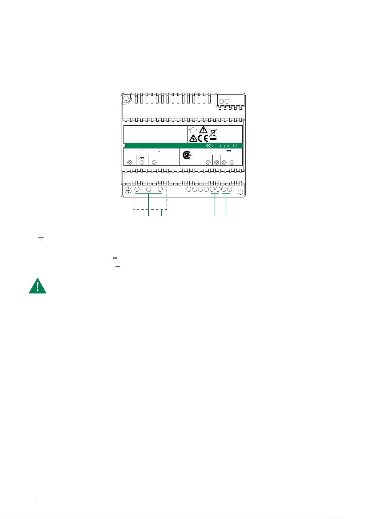
Power supply unit Art. 1209
Description
31 Vdc power supply unit for 2-wire KIT, for direct connection to the external unit and internal unit.
Equipped with overload and short circuit protection.
Input voltage 110-240 VAC.
Dimensions: 108x90x62 mm (6 DIN modules).
Dopo un cortocircuito,per ripristinare l'apparecchio,
interrompere l'alimentazione per circa 1 minuto.
To reset the operation after a short circuit,cut o mains
voltage for about 1 minute.
Apres un court circuit, pour remettre en fonction l'appareil,
interrompre l'alimentation pendant environs une minute.
INPUT/D'ENTREE
110V-240V
L
800mA
50-60Hz
N
ta=40°C
C US
257258
OUTPUT/SORTIE 31V 0.5A
1.2A 1'on/5'o
R
L1
L1
t.
Ar 1209
L2
L2
1. L N mains power input 110-240 V~
2. Terminal protection
3. L1 L1 main bus line input (31 V )
4. L2 L2 riser bus line output (31 V )
The electrical system of the building must be fitted with an (easily accessible) omnipolar mains switch with a
contact opening of at least 3 mm, which is capable of cutting off the power supply of the device.
1 2 43
6
Page 7
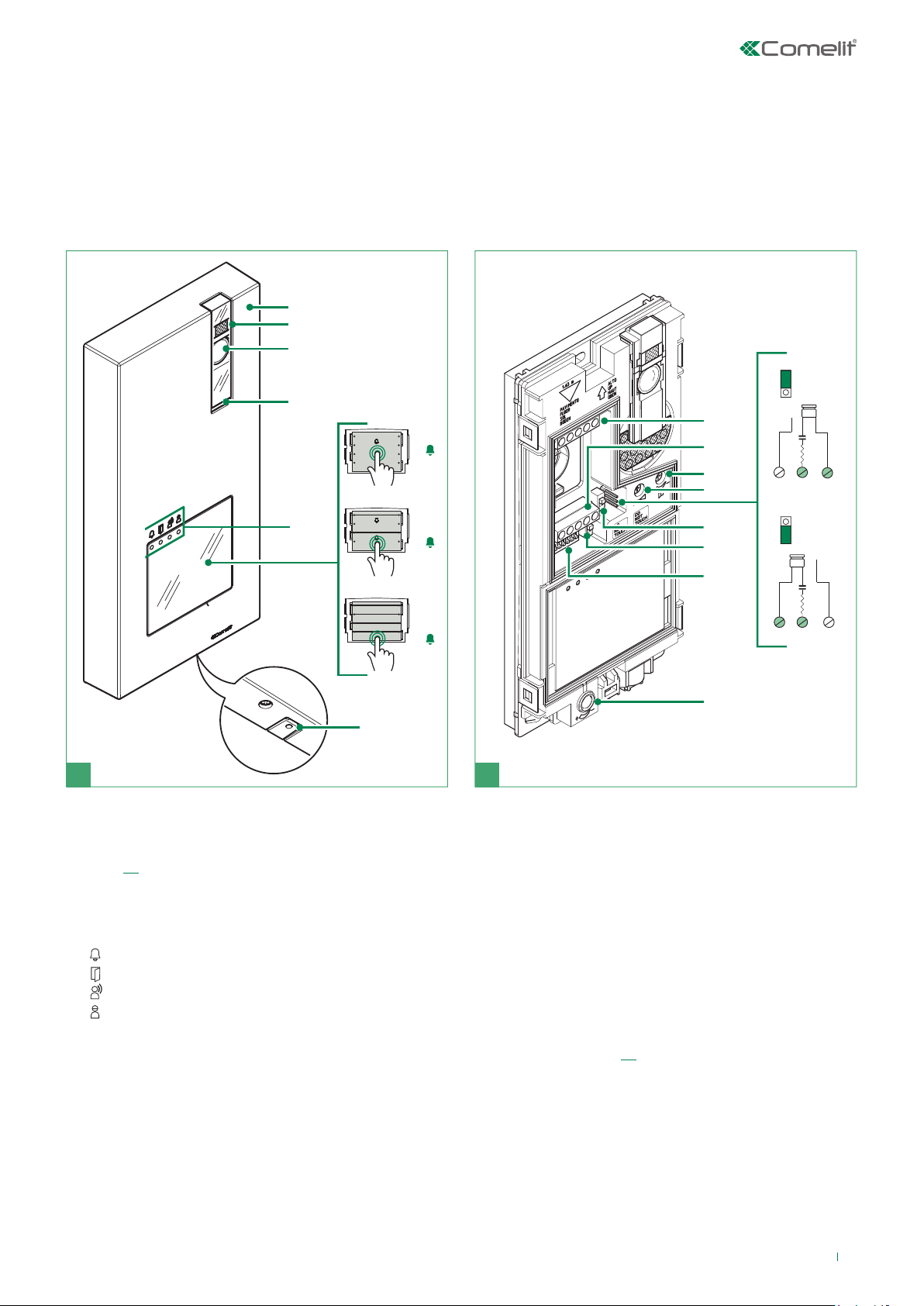
External unit Art. 4893
Description
Wall-mounted external unit for Quadra series door entry monitor. Die-cast aluminium front panel, wide-angle colour camera
and single LED for lighting at night.
Capacitive buttons with the option of setting 1 to 4 call buttons via dip switch.
Indicator LED for call sent, lock-release activated, audio activated and system busy.
Loudspeaker volume adjustment and audio balancing. Bus line power supply.
External unit dimensions: 95x195x23 mm.
1
2
3
4
8
JP1
NC
NO
1
5
1
2
6
1
2
3
4
7
1
1. Die-cast aluminium cover
2. Camera lighting LED set by default to activate in response
to a call (can be disabled by setting DIP 7 to ON, see
page 10)
3. Wide-angle colour camera
4. Loudspeaker
5. Indicator LED
call sent
lock-release enabled
audio enabled
system engaged
6. Transparent front panel with label-holder in 1 / 2 / 4
button versions (default 1 button)
f To send the call, touch the button corresponding to
the user you want to contact
7. Microphone
9
10
11
13
14
12
NO
C
JP1
NC
NO
15
NO
C
16
2
8. Terminal block M1
LL bus line connection
RTE timed local lock-release input
COM common input for RTE and DO contacts
DO door open indication input
9. Terminal block M2
SE- SE+ connection for electric door lock
NC relay normally closed contact
NO relay normally open contact
C relay common contact
10. Loudspeaker volume control
11. Audio balance
12. JP1 enable RC network for door lock fi lter on relay
contacts (see page 40)
13. CNF programming confi rmation switch
14. PR programming input/output switch
15. DIP SWITCH for function programming
16. Microphone volume control
NC
NC
7
Page 8
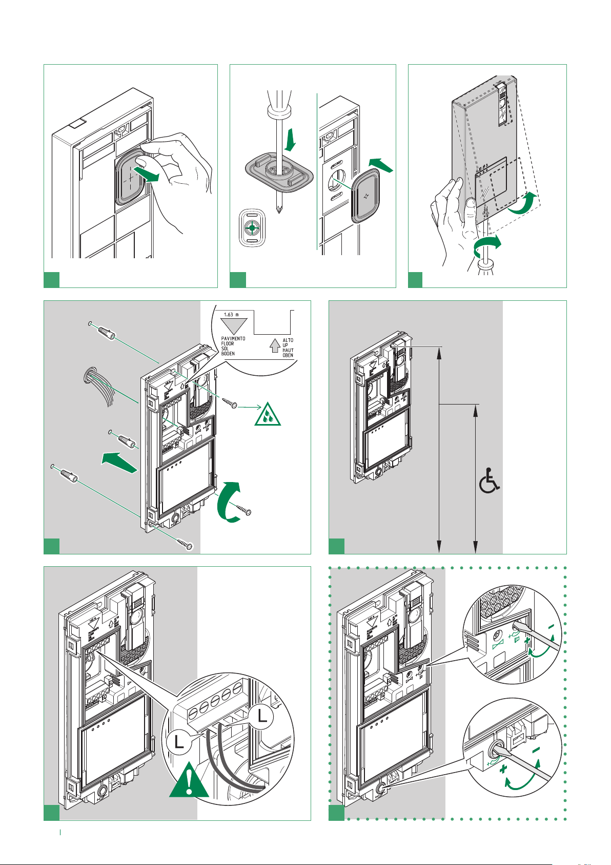
Installation
COM
L L
RTE
1
2
2
OPEN
1
21
CAUTION!
Tighten
properly to
avoid leaks
1
3
163 cm
130 cm
2
4
5
6 7
8
optional
Page 9
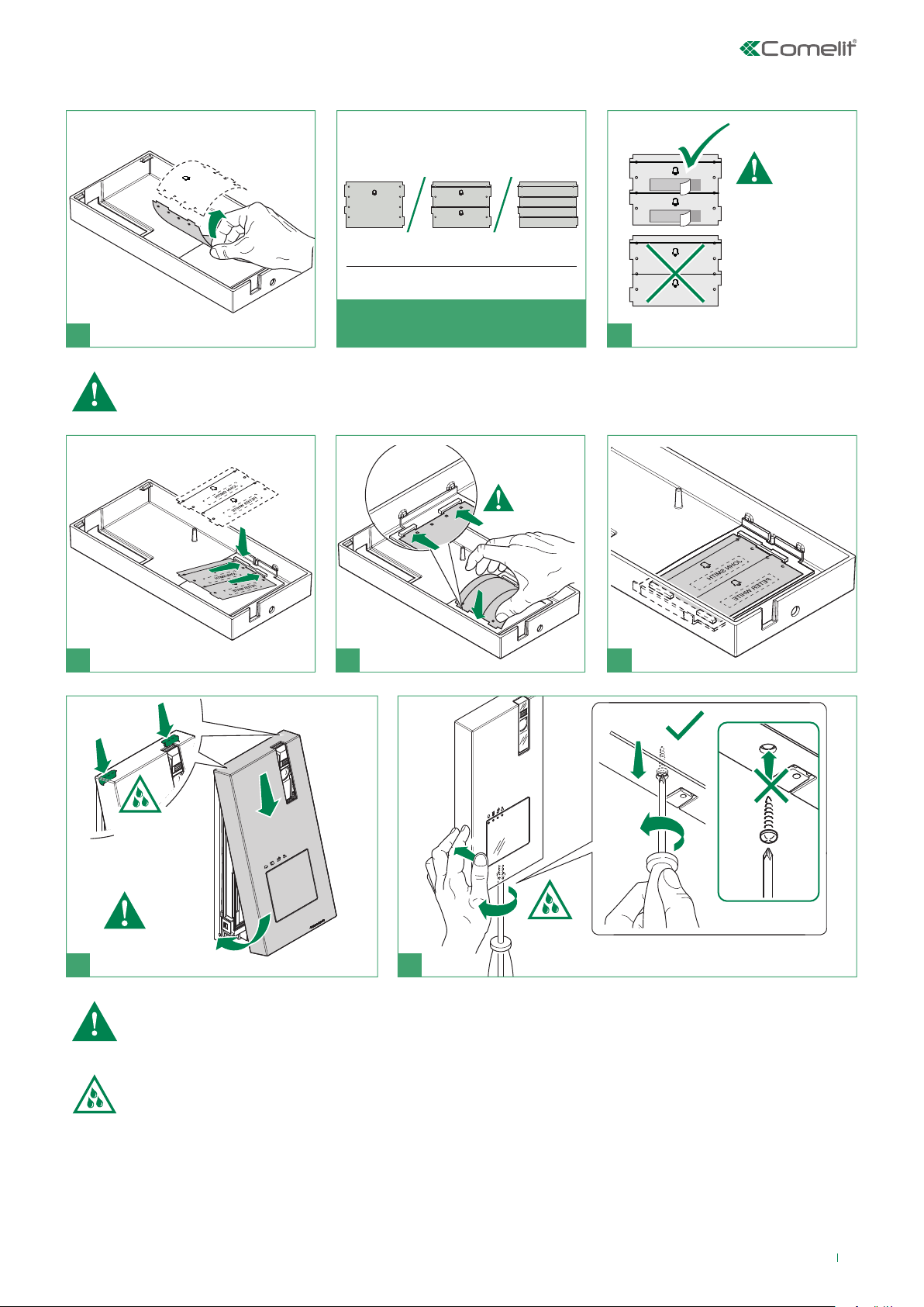
You can download the free software (Art. 1235A) from the website www.comelitgroup.com to print the entrance panel name
tags, using the adhesive pre-cut sheets available in our catalogue (Art. 1217)
REMOVE
JOHN SMITH
PETER WHIT
Replaceable nameplates
MAKE SURE THE
POSITIONING IS
CORRECT
BEFORE GLUEING
THE NAMES IN PLACE
for 1 user for 2 users for 3 users
8 9
AVAILABLE NAMEPLATES
Labels must be made of non-conductive material so as not to compromise the operation of the soft-touch buttons
1
2
10 11 12
1
1
1
Leakage
risk
2
13 14
Before fixing the screw, make sure that you do not need to programme the external unit and make sure that the
metal front panel does not rub against other metal parts, with consequent risk of damage to its insulating coating
CAUTION!: To ensure that the product remains water-tight: make sure that the fixing procedure is carried out
correctly
1
2
CLOSE
9
Page 10
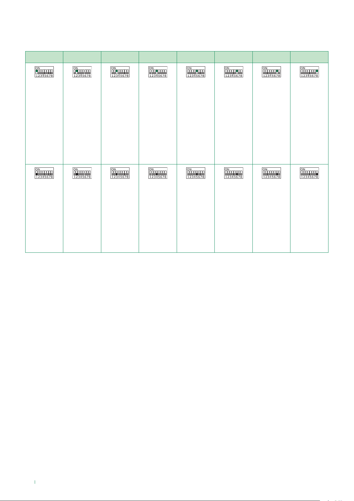
External unit settings
f Set the DIP-switches of S1 corresponding to the function that you want to programme as shown in the table below
DIP 1 DIP 2 DIP 3 DIP 4 DIP 5 DIP 6 DIP 7 DIP 8
ON
The lock-
release relay
and the
second relay
are controlled
by 2 separate
buttons (e.g.
lock-release
button and
actuator
button)
OFF
The lock-
release relay
and the
second relay
are controlled
by a single
button (e.g.
lock-release
button)
ON
lock-release
activation time:
8 sec.
OFF
lock-release
activation time:
2 sec.
ON
relay activation
time: 8 sec.
OFF
relay activation
time: 2 sec.
ON
reset wait time:
1 sec.
OFF
reset wait time:
10 sec.
ON
Call
transmission:
triple
OFF
Call
transmission:
single
ON
confirmation
tones (call,
lock-release,
relay, audio
enabled):
disabled
OFF
confirmation
tones (call,
lock-release,
relay, audio
enabled):
enabled
ON
Camera
lighting LED:
disabled
OFF
Camera
lighting LED:
enabled
ON
LED lighting
of nameholder
front panels:
OFF
OFF
LED lighting
of nameholder
front panels:
ON
10
Page 11
Call address programming for 2-4 users and additional external unit
21
√ Take note of the DIP-switch settings.
example:
3 4
NOTE Fig. 3 - On the DIP-switch, set the code corresponding to the
function you want to program as shown in the table on page 11.
5
6
Reset the configuration of the DIP-switches of S1
Code Dip-Switch ON Function
1 1 button 1 enabled with call address 1 (default)
2 2 buttons 1-2 enabled with call addresses 1-2
4 3 buttons 1-2-3-4 enabled with call addresses 1-2-3-4
8 4 Porter with switching (secondary)
16 5 Secondary porter
32 6 Main porter
254 2,3,4,5,6,7,8 Restore default
11
Page 12
Programming a generic call address
example:
√ Take note of the DIP-switch settings.
21
3 4
NOTE Fig. 3 - Set the user code on Dip Switches S1
(see table A on page 13).
1
2
3
4B
Reset the configuration of the DIP-switches of S1
5
12
Page 13

Riser addresses
TAB. A
Dip switch
Code
ON
1 1 31 1,2,3,4,5 61 1,3,4,5,6 91 1,2,4,5,7 121 1,4,5,6,7 151 1,2,3,5,8 181 1,3,5,6,8 211 1,2,5,7,8
2 2 32 6 62 2,3,4,5,6 92 3,4,5,7 122 2,4,5,6,7 152 4,5,8 182 2,3,5,6,8 212 3,5,7,8
3 1,2 33 1,6 63 1,2,3,4,5,6 93 1,3,4,5,7 123 1,2,4,5,6,7 153 1,4,5,8 183 1,2,3,5,6,8 213 1,3,5,7,8
4 3 34 2,6 64 7 94 2,3,4,5,7 124 3,4,5,6,7 154 2,4,5,8 184 4,5,6,8 214 2,3,5,7,8
5 1,3 35 1,2,6 65 1,7 95 1,2,3,4,5,7 125 1,3,4,5,6,7 155 1,2,4,5,8 185 1,4,5,6,8 215 1,2,3,5,7,8
6 2,3 36 3,6 66 2,7 96 6,7 126 2,3,4,5,6,7 156 3,4,5,8 186 2,4,5,6,8 216 4,5,7,8
Code
Dip switch
ON
Code
Dip switch
ON
Code
Dip switch
ON
Code
Dip switch
ON
Code
Dip switch
ON
Code
Dip switch
ON
Code
Dip switch
ON
1,2,3
7
8 4 38 2,3,6 68 3,7 98 2,6,7 128 8 158 2,3,4,5,8 188 3,4,5,6,8 218 2,4,5,7,8
9 1,4 39 1,2,3,6 69 1,3,7 99 1,2,6,7 129 1,8 159 1,2,3,4,5,8 189 1,3,4,5,6,8 219 1,2,4,5,7,8
10 2,4 40 4,6 70 2,3,7 100 3,6,7 130 2,8 160 6,8 190 2,3,4,5,6,8 220 3,4,5,7,8
1,2,4
11
12 3,4 42 2,4,6 72 4,7 102 2,3,6,7 132 3,8 162 2,6,8 192 7,8 222 2,3,4,5,7,8
13 1,3,4 43 1,2,4,6 73 1,4,7 103 1,2,3,6,7 133 1,3,8 163 1,2,6,8 193 1,7,8 223 1,2,3,4,5,7,8
14 2,3,4 44 3,4,6 74 2,4,7 104 4,6,7 134 2,3,8 164 3,6,8 194 2,7,8 224 6,7,8
1,2,3,4
15
16 5 46 2,3,4,6 76 3,4,7 106 2,4,6,7 136 4,8 166 2,3,6,8 196 3,7,8 226 2,6,7,8
17 1,5 47 1,2,3,4,6 77 1,3,4,7 107 1,2,4,6,7 137 1,4,8 167 1,2,3,6,8 197 1,3,7,8 227 1,2,6,7,8
18 2,5 48 5,6 78 2,3,4,7 108 3,4,6,7 138 2,4,8 168 4,6,8 198 2,3,7,8 228 3,6,7,8
19 1,2,5 49 1,5,6 79 1,2,3,4,7 109 1,3,4,6,7 139 1,2,4,8 169 1,4,6,8 199 1,2,3,7,8 229 1,3,6,7,8
20 3,5 50 2,5,6 80 5,7 110 2,3,4,6,7 140 3,4,8 170 2,4,6,8 200 4,7,8 230 2,3,6,7,8
1,3,5
21
1,3,6
37
1,4,6
41
1,3,4,6
45
1,2,5,6
51
1,2,7
67
1,2,3,7
71
1,2,4,7
75
1,5,7
81
101
105
111
1,6,7
97
1,3,6,7
1,4,6,7
1,2,3,4,6,7
127
131
135
141
1,2,3,4,5,6,7
1,2,8
1,2,3,8
1,3,4,8
157
161
165
171
1,3,4,5,8
1,6,8
1,3,6,8
1,2,4,6,8
187
191
195
201
1,2,4,5,6,8
1,2,3,4,5,6,8
1,2,7,8
1,4,7,8
217
221
225
231
1,4,5,7,8
1,3,4,5,7,8
1,6,7,8
1,2,3,6,7,8
22 2,3,5 52 3,5,6 82 2,5,7 112 5,67 142 2,3,4,8 172 3,4,6,8 202 2,4,7,8 232 4,6,7,8
23 1,2,3,5 53 1,3,5,6 83 1,2,5,7 113 1,5,6,7 143 1,2,3,4,8 173 1,3,4,6,8 203 1,2,4,7,8 233 1,4,6,7,8
24 4,5 54 2,3,5,6 84 3,5,7 114 2,5,6,7 144 5,8 174 2,3,4,6,8 204 3,4,7,8 234 2,4,6,7,8
1,4,5
25
2,4,5
26
27
1,2,4,5
28 3,4,5 58 2,4,5,6 88 4,5,7 118 2,3,5,6,7 148 3,5,8 178 2,5,6,8 208 5,7,8 238 2,3,4,6,7,8
29 1,3,4,5 59 1,2,4,5,6 89 1,4,5,7 119 1,2,3,5,6,7 149 1,3,5,8 179 1,2,5,6,8 209 1,5,7,8 239 1,2,3,4,6,7,8
30
2,3,4,5
1,2,3,5,6
55
4,5,6
56
57
1,4,5,6
60
3,4,5,6
1,3,5,7
85
2,3,5,7
86
87
1,2,3,5,7
90
2,4,5,7
115
116
117
120
1,2,5,6,7
3,5,6,7
1,3,5,6,7
4,5,6,7
145
146
147
150
1,5,8
2,5,8
1,2,5,8
2,3,5,8
175
176
177
180
1,2,3,4,6,8
5,6,8
1,5,6,8
3,5,6,8
205
206
207
210
1,3,4,7,8
2,3,4,7,8
1,2,3,4,7,8
2,5,7,8
235
236
237
240
1,2,4,6,7,8
3,4,6,7,8
1,3,4,6,7,8
5,6,7,8
13
Page 14

Description of Monitor Art. 6721W
7
8
2
1
3
4
6
9
10
11
12
13
1
5
2
1. Brightness control
f To increase the value, turn clockwise
2. Loudspeaker volume control
f To increase the value, turn clockwise
3. 4.3’’LCD colour screen
4. Call volume adjustment (high - medium - low)
5. Soft-touch keys
6. Speaker and audio activation key
7. S1 Micro-switches for user code setting (see table on page 13)
8. S2 Micro-switches for programming keys and functions
DIP 1-2-3-4 for key function programming
DIP 5-6 access to programming
DIP 7 for power supply voltage management (see diagrams and variants on page 29) default = ON
DIP 8:
ON secondary monitor
OFF main monitor (default)
A maximum of 1 main monitor can be set
9. Factory setting - DO NOT CHANGE!
10. Factory setting - DO NOT CHANGE!
11. CV 5 Video closing jumper
12. Pin for securing terminal block
13. Space for housing additional keys (Art. 6734W)
Terminal block for system connection
LL Bus line connection terminals
CFP1 CFP2 Outside door call input
14
Page 15

Soft-touch key description
f Press the desired key once to activate the function associated with it
Wait for approximately 1 sec. before pressing the same key again. Pressing the same key several times in quick
succession will cancel the command.
Lock-release key
Key 1 Actuator function (programmable)
Key 2 Self-ignition function (programmable)
Privacy key
Additional keys (programmable)
KIT with additional keysi Art. 6734W sold separately
Audio activation key
Indicator LED description
Lock-release LED
slow flashing: door open;
1 flash after pressing: door opening confirmation
continuous flashing: call in progress.
Privacy LED (red)
steady: privacy function enabled
3 flashes (every 5 sec.): doctor function enabled
continuous flashing: device in programming mode
4 flashes: system engaged
LED AUDIO (6)
steady (with call): audio activated
steady (idle): automatic answer activated
continuous flashing: incoming call
15
Page 16

Installation
115 mm
160 mm
optional
fixing
1C1B1A
32
1
4
16
5
2
6
Page 17

Removing / Fitting the terminal
L L
C
F
P
1
C
F
P
2
1
2
3
(to remove)
2
1
1
3
Fitting upgrade KIT Art. 6734W
2
2
1
1
3
2
,-.'
,-.$
+ +
3
1
1
2
2
2
2
2
1
4
5
6
7 8
17
Page 18

Operation
Answer incoming call
Press the soft-touch audio activation key to answer incoming call.
Activation/deactivation automatic answer mode
f Press on the audio activation key for 10 sec
» (ACTIVATION) + audio LED with FIXED ILLUMINATION
» (DEACTIVATION) + audio LED OFF
Monitor configuration
Standard configuration for soft-touch keys
DIP S2 Art. 6721W(/BM) + Art. 6734
DIP 1 DIP 2 DIP 3 DIP 4 P1 P2 P3 P4 P5
0 0 0 0 ACT AI NULL D NULL
1 0 0 0 NULL AI INT INTb D
0 1 0 0 INT AI INTb ACT NULL
1 1 0 0 ACT NULL NULL NULL K
0 0 1 0 ACT ACT ACT ACT ACT ACT
1 0 1 0 INT ACT NULL NULL INTb
0 1 1 0 AI D K NULL NULL
1 1 1 0 INTb INT AI INT NULL
0 0 0 1 NULL NULL D AI INTb
1 0 0 1 K NULL NULL NULL AI
0 1 0 1 NULL K NULL ACT INT
1 1 0 1 NULL NULL NULL K ACT
0 0 1 1 INTb AI INT ACT D
1 0 1 1 INT INT INT INT INT
0 1 1 1 NULL NULL NULL NULL NULL NULL
1 1 1 1 PROG
Standard configuration for DIP switches 1-2-3-4
Legend
Lock- release
ACT Actuator
AI Self-ignition
K Guardian door-entry phone call
D Doctor
INT General or selective programmable intercom - singlefamily call standard for KIT 8461
INTb General or selective programmable intercom - two-family call standard for KIT 8461
NULL No function or DO NOT use
Programmed functions, see pages 19-23.
PROG
18
In this Dip switch setting, the buttons control the programmed functions; the NON-programmed buttons
control functions referred to on line 0000 (default).
Page 19

Advanced monitor configuration
DIP OFF
DIP ON
Warning
If the default settings (see table on page 18) do not reflect requirements, the keys can be programmed dierently by carrying
out the steps below.
At the end, set S2 DIP switches 1-2-3-4 to the combination 1111 (PROG setting in the configuration tables on pages
19-23). In this dip switch setting, the keys control the programmed functions; the NON-programmed keys control
functions referred to on line 0000 (see table on page 18). Restore the user code setting on S1, see table A on page 13.
Programming for intercom call
General intercom: function allowing calls to one or more internal units identified by the same call address as used
by the external unit.
Selective intercom: function allowing calls to one or more internal units identified by a dedicated call address (see
table B, page 19) which is different from the one used by the external unit.
General and selective intercoms CANNOT be used together on the same riser.
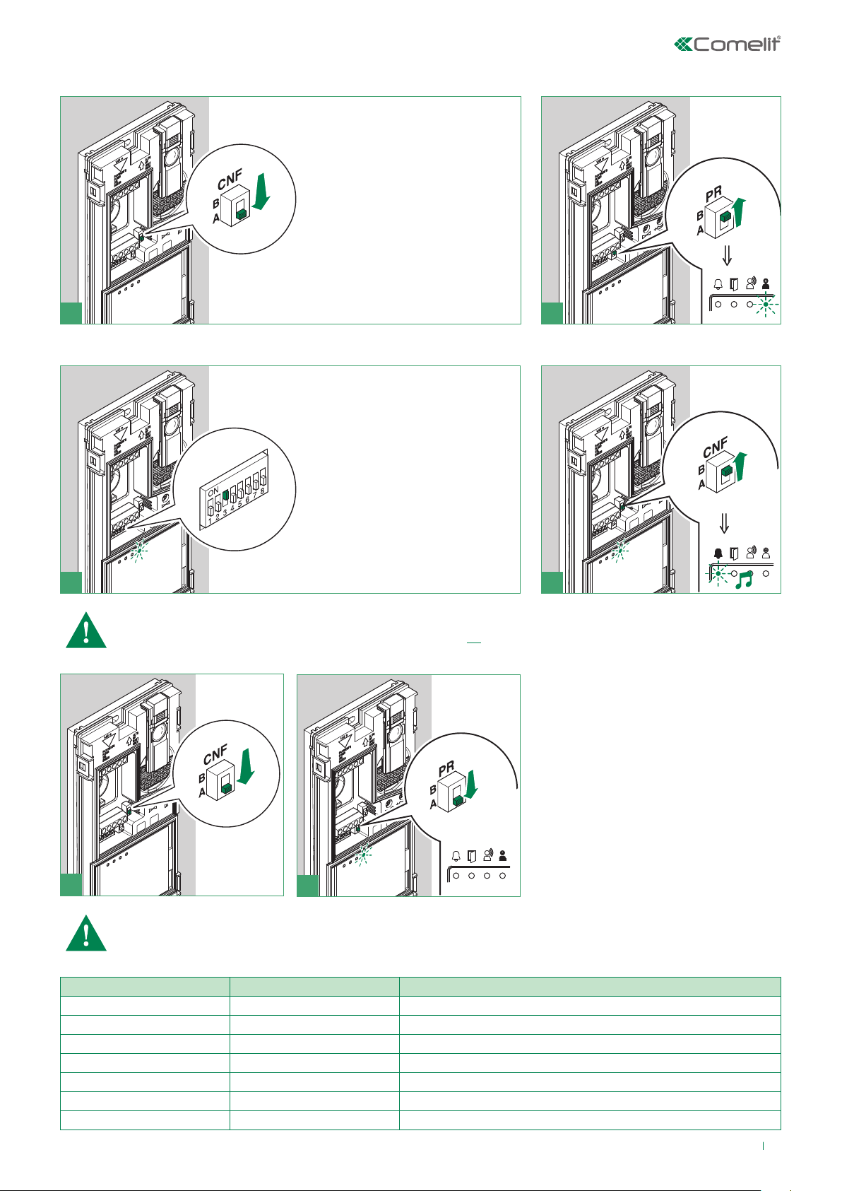
Programming/deleting intercom address
Take note of the S2, S1 setting and restore it when programming is complete
1) 2) 3)
Programming; set code,
TAB. B on page 19
S1
Cancellation
S1
Selective intercom addresses
You must set the intercom address on all the riser’s internal units.
You can assign the same intercom address to a maximum of 3 internal units.
For group calls, select the desired intercom codes simultaneously (max. 3).
Code Dip switch ON S1 Code Dip switch ON S1
S2 DIP
1 2 3 4 5 6
0 0 0 1 1 1
S2 DIP
1 2 3 4 5 6
1 1 1 1 1 1
TAB. B
S2
S2
1 1 5 5
2 2 6 6
3 3 7 7
4 4 8 8
19
Page 20

Programming buttons for intercom call
DIP S2 Art. 6721W(/BM) + Art. 6734 DIP S1
DIP 1 DIP 2 DIP 3 DIP 4 P1 P2 P3 P4 P5
0 0 0 0
1 0 0 0 INT INTb
0 1 0 0 INT INTb
1 1 0 0
0 0 1 0
1 0 1 0 INT INTb
0 1 1 0
ADDRESS
1 1 1 0 INTb INT INT
0 0 0 1 INTb
1 0 0 1
0 1 0 1 INT
1 1 0 1
0 0 1 1 INTb INT
1 0 1 1 INT INT INT INT INT
0 1 1 1
1 1 1 1 PROG
Example 1 - General intercom
on a monitor with user code 5, P3 programming = general internal call, P4 = general intercom with address 9
Example 2 - Selective intercom
on a monitor with user code 1 and intercom address 1, P3 programming = selective intercom with address 2, P4 = selective
intercom with address 3
1. Set S2 DIP switch 6 to the combination 01.
» the privacy LED flashes.
S2 DIP
1 2 3 4 5 6
0 0 0 0 0 1
S2
2. Refer to the table on page 20 and select a combination in which the intercom function (either INT or INTb) is listed for the
keys you wish to program.
E.g. 1: for P3= general internal call, set S2 DIP switches 1-2-3-4 to the combination 1000 or 0011 or 1011 (P3=INT), set S1
with address 5 in accordance with table A on page 13, go to point 3.
E.g. 1: for P4= general intercom, set S2 DIP switches 1-2-3-4 to the combination 1110 or 1011 (P4=INT), set S1 with
address 9 in accordance with table A on page 13, go to point 3.
E.g. 2: for P3= single-family intercom, set S2 DIP switches 1-2-3-4 to the combination 1000 or 0011 or 1011 (P3=INT), set
S1 with address 2 in accordance with table B on page 19, go to point 3.
E.g. 2: for P4= selective intercom, set S2 DIP switches 1-2-3-4 to the combination 1110 or 1011 (P4=INT), set S1 with
address 3 in accordance with table B on page 19, go to point 3.
3. Press and release the key to be associated with the function
» the lock-release LED lights up.
» a confirmation tone will sound.
4. To exit programming mode, set S2 DIP switches 5-6 to the combination 00
f the privacy LED switches o
5. When programming is complete, set S2 DIP switches 1-2-3-4 to the combination 1111. Restore the user code
setting on S1, see table A on page 13.
20
Page 21

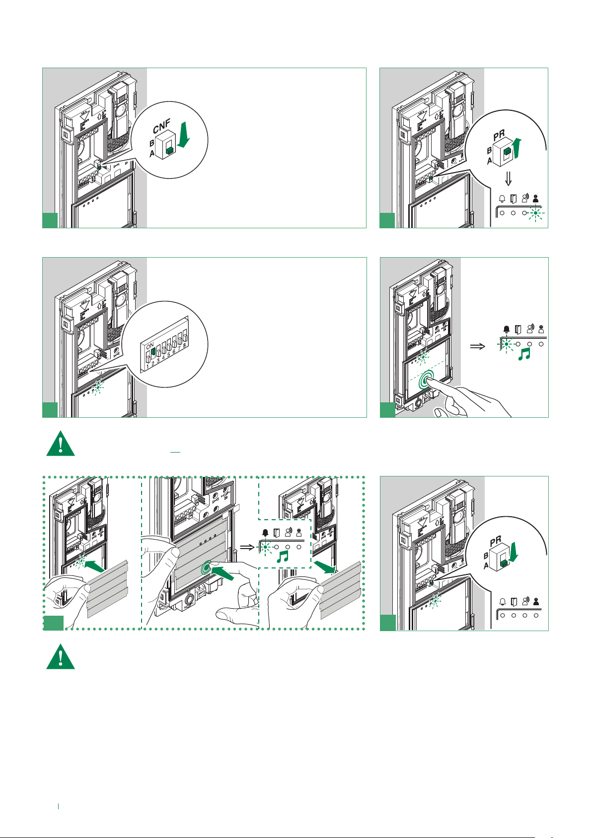
Direct programming of intercom call
Allows direct programming of intercom call via the internal units.
√ Requires 2 operators
Step 1: enter programming mode
Operator 1 and Operator 2 carry out the following procedures on 2 internal units:
1. Set S2 DIP switches 1-2 -3-4 to the combination 1111
2. Press the audio key
3. Press and hold the privacy and lock-release keys for 3 sec.
» The internal unit emits 1 tone.
» The privacy LED flashes.
» The internal unit enters audio mode.
» At this point the 2 operators will be communicating with each other.
Step 2: intercom call programming
Operator 1:
f Press the key you want to program to call operator 2 (e.g. 2).
» The internal unit manned by operator 1 emits a confirmation tone.
Operator 2:
f Press the key you want to program to call operator 1 (e.g. 1).
» The internal unit manned by operator 2 emits a confirmation tone.
Operator 1/ Operator 2:
f Press the audio key.
» The internal unit emits 1 tone.
» Programming of the 2 internal units is now complete.
To program another internal unit, move on to STEP 3.
Step 3: programming other internal units
Operator 1/ Operator 2:
1. Once the new station has been reached, carry out step 1 to begin communication
2. Repeat step 2
NOTE If a call is received during programming, it must be answered and the programming procedure resumed
afterwards.
21
Page 22

Programming keys for generic or coded actuator
DIP S2 Art. 6721W(/BM) + Art. 6734 DIP S1
DIP 1 DIP 2 DIP 3 DIP 4 P1 P2 P3 P4 P5
0 0 0 0 ACT
1 0 0 0
0 1 0 0 ACT
1 1 0 0 ACT
0 0 1 0 ACT ACT ACT ACT ACT ACT
1 0 1 0 ACT
0 1 1 0
1 1 1 0
0 0 0 1
1 0 0 1
0 1 0 1 ACT
1 1 0 1 ACT
0 0 1 1 ACT
1 0 1 1
0 1 1 1
1 1 1 1 PROG
Example:
on a monitor with user code 5, P1 programming = generic actuator, P2 = coded actuator (code 125)
Take note of the DIP-switch settings
1. Set S2 DIP switch 6 to the combination 01.
» the privacy LED flashes.
S2 DIP
1 2 3 4 5 6
0 0 0 0 0 1
S2
ADDRESS
2. Refer to the table on page 22 and select a combination in which the actuator function (ACT) is listed for the keys you
wish to program.
E.g.: for P1= generic actuator, set S2 DIP switches 1-2-3-4 to the combination 0000 or 1100 or 0010 (P1=ACT), set S1 DIP
switches to the combination 11111111, go to point 3.
E.g.: for P2= coded actuator (code 125), set S2 DIP switches 1-2-3-4 to the combination 0010 or 1010 (P2=ACT), set S1
with address 125 in accordance with table A on page 13, go to point 3.
3. Press and release the key to be associated with the function.
» the lock-release LED lights up.
» a confirmation tone will sound.
4. To exit programming mode, set S2 DIP switches 5-6 to the combination 00.
» the privacy LED switches o.
5. When programming is complete, set S2 DIP switches 1-2-3-4 to the combination 1111. Restore the user code
setting on S1, see table A on page 13.
22
Page 23

Programming buttons for other functions
DIP S2 Art. 6721W(/BM) + Art. 6734
DIP 1 DIP 2 DIP 3 DIP 4 P1 P2 P3 P4 P5
0 0 0 0 AI D
1 0 0 0 AI D
0 1 0 0 AI
1 1 0 0 K
0 0 1 0
1 0 1 0
0 1 1 0 AI D K
1 1 1 0 AI
0 0 0 1 D AI
1 0 0 1 K AI
0 1 0 1 K
1 1 0 1 K
0 0 1 1 AI D
1 0 1 1
0 1 1 1
1 1 1 1 PROG
Legend
Lock- release
AI Self-ignition
K Guardian doorentry phone call
D Doctor
PROG Programmed functions
Example:
on a monitor with user code 5, P1 programming = self-ignition, P2= Doctor.
1. Set S2 DIP switch 6 to the combination 01.
» the privacy LED flashes.
S2 DIP
1 2 3 4 5 6
0 0 0 0 0 1
S2
2. Refer to the table on page 23 and select a combination in which the desired/necessary functions are listed for the keys
you wish to program.
E.g. 1: for P1= self-ignition, P2= Doctor, set S2 DIP switches 1-2-3-4 to the combination 0110 (P1=AI,P2=D).
3. Press and release the keys to which you wish to assign the functions
» the lock-release LED lights up.
» une tonalité de confirmation retentit.
4. To exit programming mode, set S2 DIP switches 5-6 to the combination 00
» the privacy LED switches o.
5. When programming is complete, set S2 DIP switches 1-2-3-4 to the combination 1111.
23
Page 24

Programming range
DIP OFF
DIP ON
Take note of the S2, S1 setting and restore it when programming is complete
Carry out steps 1 to 4
1) 2) 3) 4)
Range minimum
address
Range maximum
address
Enable range
Disable range
Deleting the range
S1
set code, TAB. A
on page 13
S1
1 2 3 4 5 6
0 0 0 0 1 0
S2
1 2 3 4 5 6
1 1 1 1 1 0
S2
S2 DIP
S2
S2 DIP
2 sec
Monitor ringtone selection
1. Press and hold for 6 sec.
» a confirmation tone will sound
» the privacy LED will flash to indicate “programming” mode.
√ The procedure can only take place while the system is in standby; otherwise the privacy LED will flash 4 times to inform the
user that the system is engaged
2. Press and release
Once (1 confirmation tone is emitted) to change the ringtone for calls from the external unit.
Twice (2 confirmation tones are emitted) to change the ringtone for calls from the switchboard.
3 times (3 confirmation tones are emitted) to change the ringtone for intercom calls made from the internal unit.
4 times (4 confirmation tones are emitted) to change the floor door call ringtone.
Any further pressing of the key repeats the sequence described above.
3. Press and release to scroll through the various available ringtones in sequence.
4. Press to confirm selection of the last ringtone heard and to exit (at any time) change monitor ringtone mode.
» one confirmation tone is emitted
» the privacy LED switches o
5. Repeat steps 1 to 4 to change the other ringtones.
24
Page 25

Programming reset
DIP OFF
DIP ON
Factory settings:
• Button functions for the S2 DIP switch 1-2-3-4 combination;
• Intercom address absent;
• Range function and min./max. addresses absent;
• Ringtone reset.
Take note of the S2, S1 setting and restore it when programming is complete
1) 2) 3)
S1
S2 DIP
1 2 3 4 5 6
1 1 1 1 1 1
S2
5 sec
25
Page 26

Operation
To make a call from an external unit
f To send the call from an external unit, touch the button corresponding to the user you want to contact.
If the system is not busy: on the external unit the caller illumination LED will light up, the LED will flash and the
confirmation tone will sound. The video image from the external unit will appear automatically on the main internal
monitor/s. The video image can be displayed on secondary monitors (without answering the call) by pressing button 2
(programmed by default for the self-ignition function).
» If the user responds to the call: the LED will illuminate on the external unit.
» If the user presses the lock-release control: the LED will illuminate on the external unit.
If the system is busy: the led will flash and the external unit will emit the system busy tone.
When a call is made from the external unit, the monitor switched on will be the main door entry monitor.
Any other secondary monitors in the same family unit will remain o.
When responding to a call from the external unit using a secondary door entry monitor, the image is automatically displayed on
the monitor (and the main door entry monitor is switched o).
To display the image without activating audio communication with the external unit, press button 2 -self-ignition/video request.
Self-ignition
√ Self-ignition is possible only when the system is in standby
f Press the self-ignition button (button 2 by default) to display on the monitor the image transmitted from the external unit.
Operation with additional internal units
GENERAL INTERNAL CALL
General intercom: function allowing calls to one or more internal units identified by the same call address as used by the
external unit.
f Press the programmed button to send the call
If the system is not busy: The receiver of the call can press the audio key (or pick up the handset) to communicate with
the caller. Press the audio button again (or hang up the handset) to terminate the call.
If the system is busy: the LED indicator light will flash for a few seconds (on Mini monitors the privacy LED will flash 4
times).
A call from the external unit always takes priority over an intercom communication. In this case, users who are already
speaking will hear a tone similar to the ringtone, if the call is addressed to them, or otherwise a triple signalling tone will sound
and the video image from the external unit from which the call was made will appear (in the case of a main monitor).
f Press the audio button twice (or hang up the handset and pick it up again) to terminate the call in progress or establish a
communication with the external unit.
SELECTIVE INTERCOM
Selective intercom: function allowing calls to one or more internal units identified by a dedicated call address (see table B,
page 19), which is dierent to the call address used for external unit calls.
MAIN/SECONDARY MONITORS
The KIT can manage up to a maximum of 4 door entry monitors or door-entry phones for each call button, including a
maximum of 1 main door entry monitor.
Operation with additional external units
Consult page 11 onwards for programming information.
• External unit (Porter) with switching (secondary): default function to be used also in systems with switching device Art.
1404 (for installations with 3 or more entrances) (see diagrams MNVK/017QC, MNVK/017CQC).
• Secondary external unit (Porter): function to be used in systems with switching device Art. 1405 and 2 external units (see
diagram MNVK/017AQC).
• Main external unit (Porter): function to be used in systems with switching device Art. 1405 and 2 external units (see
diagram MNVK/017AQC).
26
Page 27

OPERATION WITH SWITCHING DEVICE ART. 1404 (DEFAULT)
In the configuration of Art. 1404, the MIN and MAX Dip switches define respectively the lowest and highest user codes
which can be connected to the riser. For information on setting the desired values, refer to the table on page 13. Separate
switching devices for dierent risers must manage code ranges which are not overlapping.
The self-ignition function is only available for systems as depicted in diagram MNVK/017CQC (for each internal unit, it is
possible to toggle between the external unit of the KIT and the main external unit).
OPERATION WITH SWITCHING DEVICE ART. 1405
With the switching device Art. 1405 it is possible to install only 1 main external unit and 1 secondary external unit.
In “Main external unit” mode, lock release (or actuator) commands are only executed if the external unit is in call or self-ignition
mode. The “door-open” function is always deactivated.
In “Secondary external unit” mode, lock release (or actuator) commands are executed if the system is in standby mode or if the
external unit is active.
If the system is in standby mode the first self-ignition command will activate the camera of the secondary external unit. Further
commands will toggle between the external units, activating alternately the main external unit and the secondary external unit.
Additional door-entry phones Art. 2638
1
2
3
1
1. Privacy function indicator
2. Key button
3. Button P1 generic actuator / button for various uses
present on terminal block (P1 C1)
4. 3-position ringtone/Privacy service selector:
High position: Maximum ringtone volume.
Middle position: Medium ringtone volume.
Low position: Privacy service activation. (Privacy service
means exclusion of the call ringtone from the external
unit and switchboard; activation of the Privacy function is
signalled by a red indicator appearing at the top righthand side).
4
2
5. Trimmer for adjusting the microphone volume
6. U2 DIP switch for setting user code
7. System connection terminals:
L L bus line connection.
CFP CFP Floor door call input.
P1 C1 terminals for pushbutton P1 C.NO. 24V 100mA
dedicated to various services (remove CV1 and CV2).
S+ S- terminals for call repetition device
8. JP2 jumper for selecting the Switchboard call (position C)
/ Generic actuator (position A) function of button P1
9. CV1 CV2 jumpers to be removed in order to obtain a
voltage free C. NO contact on button P1
5
6
7
8
9
27
Page 28

Installation of door-entry phone Art. 2638
140-145 cm
115-125 cm
21
4
5
3
6
87
Programming of door-entry phone Art. 2638
Set the user code on Dip Switches U2 as indicated in the table on page 13.
28
9
Page 29

Wiring diagrams
6721W
KIT 8461V: standard single-family system.
Switching on/voltage check with system in standby
C
C
F
F
1
6721W/BM
LL
2
P
P
110-240V
1209
L2
L2
L1
L1
ON
S1 S2
L
N
85 764321
A
30 Vdc
30 Vdc
ON
12 34 675 8
P
SE
-
SE
+
NO
NC C
LL
*
R
C
T
O
E
M
4893
Local lock release button.
*
D
O
MNVK/039QC
29
Page 30

KIT 8461V: expansion for two-family system
C
6721W
6721W/BM
+6710
ON
85 764321
A
S1 S2
ON
123 4 675 8
P
C
F
F
2
1
LL
P
P
LM
LM
1214/2C
1216
L
OUT
OUT
L
INLIN
L
OUT
OUT
INLIN
LL
1214/2C
L
L
LM
L
LM
6721W
6721W/BM
C
F
1
LL
P
ON
S1 S2
C
F
2
P
ON
85 764321
123 4 675 8
A
P
110-240V
1209
L
N
L2
L2
L1
L1
R
C
SE
SE
NO
NC C
+
-
D
T
O
LL
O
E
M
4893
8461V
Additional monitors Art. 6721W/BM do not include a backplate.
# To program the special function “buttons 1-2 enabled with call addresses 1-2” see page 11.
Local lock release button.
*
30
MNVK/040QC
Page 31

KIT 8461V: expansion for 4-user system
1216
6721W
6721W/BM
+6710
ON
85 764321
A
S1 S2
6721W
6721W/BM
+6710
ON
85 764321
A
S1 S2
ON
123 4 6 75 8
ON
123 4 6 75 8
C
C
F
F
1
2
LL
P
P
LL
1214/2C
L
P
1214/2C
C
C
F
F
2
1
LL
P
P
L
OUT
OUT
LM
L
LM
L
OUT
INLIN
OUT
INLIN
L
L
6721W
6721W/BM
+6710
LM
LM
C
F
1
LL
P
ON
S1 S2
C
F
2
P
ON
85 764321
123 4 6 75 8
A
P
1214/2C
L
P
1214/2C
L
OUT
OUT
LM
L
LM
INLIN
C
C
F
1
LL
P
ON
S1 S2
F
2
P
ON
85 764321
123 4 6 75 8
A
P
L
OUT
INLIN
OUT
L
L
6721W
6721W/BM
LM
LM
Additional monitors Art.
6721W/BM do not include a
backplate.
# To program the special
function “buttons 1-2-3-4
enabled with call addresses
1-2-3-4” see page 11.
Local lock release button.
*
110-240V
1209
L
N
L2
L2
L1
L1
*
R
C
SE
SE
NO
NC C
+
-
D
T
O
LL
O
E
M
4893
8461V
#
MNVK/041QC
31
Page 32

KIT 8461V: expansion with second external unit 4893 and switching device Art. 1405
C
6721W
6721W/BM
L1 L1 L2 L2
LMLMLSL
C
F
F
1
LL
P
P
ON
S1 S2
L
110-240V
LPL
S
2
A
1405
P
85 764321
N
ON
123 4 675 8
P
1209
SE
SE
+
-
4893
NO
NC C
C
D
T
O
LL
O
E
M
SE
SE
NO
NC C
+
-
R
C
D
T
O
LL
O
E
M
4893
R
MAINSLAVE
8461V
# To program the special functions “Main external unit (Porter)” and “Secondary external unit (Porter)”, see page 11.
For further information regarding operating modes, please refer to Operation section, page 26.
Local lock release button.
*
N.C. contact for door open indication.
**
Door open indication not available.
***
MNVK/017AQC
32
Page 33

KIT 8461V: expansion with 3 external units 4893 and switching device Art. 1404
110-240V
6721W
C
C
F
F
2
1
LL
P
6721W/BM
P
ON
85 764321
A
S1 S2
ON
1234 675 8
P
1209
IN
LP
OUT
110-240V
1404
JP1
A
B
L
N
L2
L2
L1
L1
ON
85 764321
LMLMLSLSLP
85 764321
MAX
MIN
ON
ON
85 764321
L
N
L2
L2
L1
L1
LMLMLSLSLP
85 764321
MAX
MIN
ON
1209
1404
LP
IN
OUT
JP1
A
B
L
110-240V
N
L2
L2
L1
L1
1209
** *
R
C
SE
SE
NO
NC C
+
-
D
T
O
LL
O
E
M
SE
SE
NO
NC C
+
-
4893
R
C
D
T
O
LL
O
E
M
SE
SE
NO
NC C
+
-
4893
R
C
D
T
O
LL
O
E
M
4893
Local lock release button.
*
The function “External unit (Porter) with switching (secondary)” is active by default (see Operation section,
page 26).
The self-ignition and door open indication functions are not available.
8461V
MNVK/017QC
33
Page 34

Wiring diagram for system with 2 single-family KITS KIT 8461V and main external unit Art.
1216
1216
4893
ON
MIN
1214/2C
ON
85 764321
MAX
L
OUT
OUT
INLIN
LMLMLSLSLP
85 764321
LL
L
L
6721W
6721W/BM
LM
LM
LL
C
C
F
1
LL
P
ON
S1 S2
F
2
P
ON
85 764321
1234 675 8
A
P
6721W
6721W/BM
C
F
1
LL
P
ON
S1 S2
C
F
2
P
ON
85 764321
1234 675 8
A
P
1214/2C
L
L
OUT
OUT
LM
L
LM
INLIN
1404
LP
IN
OUT
JP1
A
B
ON
MIN
MAX
ON
LMLMLSLSLP
85 764321
85 764321
1404
LP
IN
OUT
JP1
A
B
110-240V
1209
L
N
L2
L2
L1
L1
R
C
SE
SE
NO
NC C
+
-
D
T
O
LL
O
E
M
SE
SE
NO
NC C
+
-
LL
4893
R
T
E
4893
L
110-240V
N
L2
L2
L1
L1
1209
C
D
O
O
M
SE
SE
NO
NC C
+
-
8461V8461V
# To program the special function “buttons 1-2 enabled with call addresses 1-2” see page 11.
## To program the call address, see page 12 - 13.
Local lock release button.
*
The function “External unit (Porter) with switching (secondary)” is active by default (see page 26).
The door open indication function is not available.
The self-ignition function is available (with toggle function between 2 external units)
L
110-240V
N
L2
L2
L1
L1
1209
R
C
D
T
O
LL
O
E
M
4893
34
MNVK/017CQC
Page 35

KIT 8461V: additional actuator relay Art. 1256
C
L
LINL
OUT
LL
L
IN
C
F
F
1
2
P
P
ON
85 764321
A
S1 S2
1256
1
JP4
2
1214/2C
LM
LM
ON
123 4 675 8
N
CNL L
C
6721W
6721W/BM
OUT
P
JP3
O
JP2
12
2 1
1200
~-~
230V~
+
12V~
12/24V
AC/DC
110-240V
1209
L
N
L2
L2
L1
L1
# For further information see the respective
manual.
Local lock release button.
*
R
C
SE
SE
NO
NC C
+
-
D
T
O
LL
O
E
M
4893
8461V
MNVK/EQC
35
Page 36

KIT 8461V: additional remote camera module Art. 1409
C
6721W
6721W/BM
C
F
LL
P
ON
S1 S2
F
1
2
P
ON
85 764321
123 4 6 75 8
A
P
110-240V
1209
L
N
L2
L2
L1
L1
OUT
1409
G
I
OUT
IN IN
LLL
~ ~
-
+
L
V
NDAN
V S
3
32SV2S11
ON
123 4 6 75 8
230V~
1200
12V~
R
C
SE
-
SE
+
NO
NC C
LL
D
T
O
O
E
M
4893
8461V
# To be powered separately. For the setting and operation of Art.1409 see the respective manual.
Local lock release button.
*
36
MNVK/015QC
Page 37

KIT 8461V: additional 2 secondary monitors in cascade connection
1209
CV5
6721W
6721W/BM
CV5
1214/2C
1214/2C
C
LL
C
F
F
2
1
P
P
ON
85 764321
A
S1 S2
ON
123 4 675 8
P
P
6721W
6721W/BM
+6710
LL
C
C
F
F
1
2
P
P
ON
85 764321
A
S1 S2
ON
123 4 675 8
P
S
6721W
6721W/BM
+6710
LL
C
C
F
F
1
2
P
P
ON
85 764321
A
S1 S2
Additional monitors Art. 6721W/BM do not include a backplate.
MNVK/Q23
Connection diagram for two-family system with one main monitor and 2 secondary
monitors (cascade connection)
ON
123 4 675 8
P
S
1216
L
OUT
INLIN
L
OUT
INLIN
LL
L
OUT
L
L
OUT
L
6721W
6721W/BM
LM
LM
6721W
6721W/BM
LM
LM
LL
LL
CV5
C
C
F
F
1
2
P
P
ON
A
S1 S2
CV5
C
C
F
F
1
2
P
P
ON
A
S1 S2
85 764321
85 764321
ON
1234 675 8
P
ON
1234 675 8
P
P
P
6721W
6721W/BM
+6710
6721W/BM
+6710
LL
LL
CV5
C
C
F
F
1
2
P
P
ON
1234 675 8
A
S1 S2
CV5
C
C
F
F
1
2
P
P
ON
1234 675 8
A
S1 S2
C
LL
C
F
F
1
2
P
P
ON
1234 675 8
S1 S2
ON
1234 675 8
6721W
6721W/BM
+6710
P
S S
C
LL
C
F
F
1
2
P
P
ON
1234 675 8
S1 S2
ON
1234 675 8
6721W6721W
6721W/BM
+6710
P
S S
A
A
ON
1234 675 8
ON
1234 675 8
P
P
1209
Additional monitors Art. 6721W/BM do not include a backplate.
MNVK/Q21
37
Page 38

Connection diagram for system with maximum expansion in branch connection for single
CV5
1214/2C
CV5
CV5
6228W
1214/2C
call address
C
1214/2C
1214/2C
1216
L
OUT
INLIN
L
OUT
INLIN
1209
LL
L
OUT
L
L
OUT
L
6721W
6721W/BM
+6710
LM
LM
6721W
6721W/BM
LM
LM
LL
LL
C
F
F
1
2
P
P
ON
A
S1 S2
CV5
C
C
F
F
2
1
P
P
ON
A
S1 S2
ON
85 764321
1234 6 75 8
ON
85 764321
1234 6 75 8
6721W
6721W/BM
+6710
P
6721W
6721W/BM
+6710
P
P
LL
LL
C
C
F
F
1
2
P
P
ON
1234 6 75 8
A
S1 S2
C
C
F
F
2
1
P
P
ON
1234 6 75 8
A
S1 S2
ON
1234 6 75 8
P
SS
ON
1234 6 75 8
P
S
Additional monitors Art. 6721W/BM do not include a backplate.
MNVK/Q22
Connection diagram for cascade connection from internal video unit of additional doorentry phones Art. 2610 and Art. 6228(B)(W)
C
6721W
6721W/BM
ON
85 764321
A
S1 S2
ON
1234 675 8
C
C
6721W
F
F
2
1
LL
P
P
6721W/BM
+6710
ON
P
P
85 764321
A
S1 S2
ON
1234 675 8
S
P
C
C
F
F
2
1
LL
P
P
L L
1216
L
L
OUT
OUT
LM
L
LM
INLIN
1214/2C
L L
C
F
P
C
P C S
F
P
ON
S1
S
33
+
2610
-
SW3
S2 S1
85 764321
L L
C
S+S
F
F
P
P
ON
S1
6228B
-
6228W
SW1
S2 S1
85 764321
1209
Additional monitors Art. 6721W/BM do not include a backplate.
Connection diagram for branch connection from internal video unit of additional door-
MNVK/AAD
entry phones Art. 2610 and Art. 6228(B)(W)
38
1209
6721W
6721W/BM
L
OUT
LINL
LL
L
OUT
LM
LM
IN
1214/2C
C
C
F
F
1
P
P
ON
2
S1 S2
A
85 764321
ON
1234 675 8
C
C
C
P C S
S
F
F
L L
P
33
+
P
-
P
SW3
S2 S1
2610
C
F
F
LL
-
P
P
6228B
S+S
SW1
S1S2
MNVK/AAE
Page 39

Connection diagram for branch connection from riser of additional door-entry phones
1214/2C
1214/2C
1214/2C
6228W
1209
6721W
Art. 2738W and Art. 6228(B)(W)
6721W/BM
1214/2C
C
OUT
OUT
OUT
L
L
L
LINL
L
L
C
F
F
L L
P
P
L
OUT
LM
LM
INLIN
C
C
S+S
F
F
LL
L
OUT
LM
LM
IN
LL
L
OUT
LM
LM
INLIN
-
P
P
C
C
F
P
S
F
+
2 2
P
2738W
6228B
SW1
S1S2
SCP
-
2610
SW3
S2 S1
Door open indication use variant
110-240V
1209
SE
SE
+
-
L
N
L2
L2
L1
L1
NO
NC C
MNVK/FC
# active input closed for DOOR OPEN
#
R
C
D
T
O
LL
O
E
M
signal.
4893
In systems with Art. 1405 the “door open indication” function can only be used on the secondary external unit.
In systems with Art. 1404 the “door open indication” function cannot be used.
MNVK/DO
39
Page 40

Variant with security door lock and additional power supply
4893
L
L
CFP
CFP
JP1
JP1
NO
JP1
NO
12/24V
AC/DC
Local lock release button.
*
*
R
C
SE
-
SE
NC C
+
NO
LL
D
T
O
O
E
M
SB2/SNPQ
Floor door call connection variant
If there are a number of door-entry phones or monitor brackets with the same user code, connect the CFP button to one
only; all the devices will ring simultaneously.
20 m MAX - Use screened cable for the connection and do not run cables near heavy inductive loads or power supply
*
cables (230V / 400V).
Using the RC network for door lock filter on relay contacts
On contacts C. NO. On contacts C. NC. Disabled: clean contact
NC
NO
NO
C
NC
C
40
NC
NO
NC
NC
NO
C NC
Page 41

41
Page 42

2 ed. - 1rev. 04/2017
cod. 2G40001601
CERTIFIED MANAGEMENT SYSTEMS
www.comelitgroup.com
Via Don Arrigoni, 5 - 24020 Rovetta (BG) - Italy
 Loading...