

Page 1
!
Installation Instructions
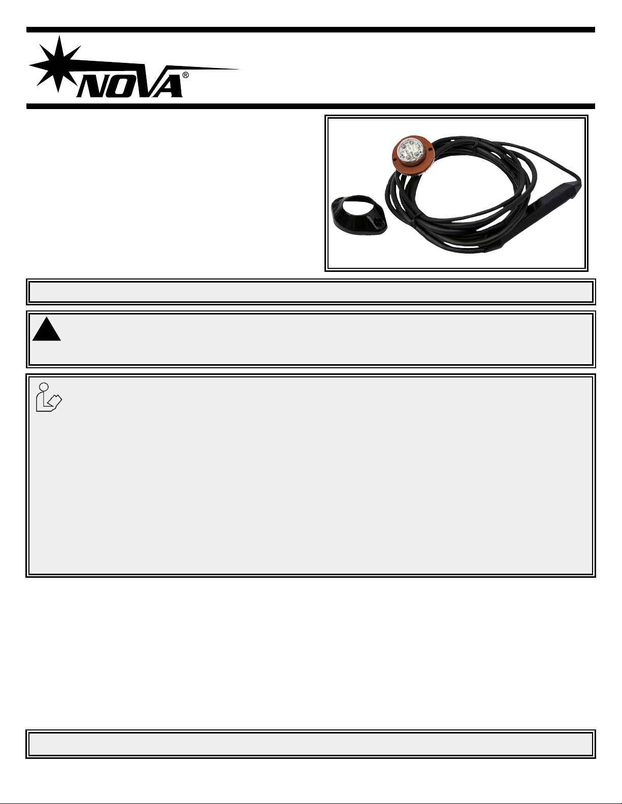
V Series Hide-A-LEDs
The V Series Hide-A-LED™provides exceptional warning capability
in a compact light that can be either mounted inside a head/tail light
casing or surface mounted using the included bezel. Using 6 high
intensity LEDs the V Series features 12 or 24 VDC operation, 16
ash patterns, the ability to synchronize with additional units and a
9’ cable.
IMPORTANT! Read all instructions before installing and using. Installer: This manual must be delivered to the end user.
WARNING!
Failure to install or use this product according to manufacturer’s recommendations may result in property damage, serious
bodily/personal injury, and/or death to you and those you are seeking to protect!
Do not install and/or operate this safety product unless you have read and understand the safety
information contained in this manual.
1. Proper installation combined with operator training in the use, care, and maintenance of emergency warning devices are
essential to ensure the safety of you and those you are trying to protect.
2. Exercise caution when working with live electrical connections.
3. This product must be properly grounded. Inadequate grounding and/or shorting of electrical connections can cause high
current arcing, which can cause personal injury and/or severe vehicle damage, including re.
4. Proper placement and installation are vital to the performance of this warning device. Install this product so that output
performance of the system is maximized and the controls are placed within convenient reach of the operator so that s/he can
operate the system without losing eye contact with the roadway.
5. It is the responsibility of the vehicle operator to ensure during use that all features of this product work correctly. In use, the
vehicle operator should ensure the projection of the warning signal is not blocked by vehicle components (i.e., open trunks
or compartment doors), people, vehicles, or other obstructions.
6. The use of this or any other warning device does not ensure all drivers can or will observe or react to a warning signal.
Never take the right-of-way for granted. It is your responsibility to be sure you can proceed safely before entering an
intersection, driving against trafc, responding at a high rate of speed, walking on or around trafc lanes.
7. This equipment is intended for use by authorized personnel only. The user is responsible for understanding and obeying
all laws regarding warning signal devices. Therefore, the user should check all applicable city, state, and federal laws and
regulations. The manufacturer assumes no liability for any loss resulting from the use of this warning device.
Contents:Specications:
Size: 0.87H x Dia. 1.51
Input Voltage: 12/24 VDC
Current Draw: 0.7A Max
Operating temperature range: -30 to +50ºC
Lumens: VA(Amber) 200
VB(Blue) 100
VR(Red) 200
VW(White) 460
1 X HIDE-A-LED head with built-in power module and cable
1 X Mounting Gasket
2 X #6 X 1/2” Screws
1 X Bezel
Installation & Mounting:
Before installation, examine the LED heads for transit damage. Do not use damaged or broken parts.
Important! This unit is a safety device, and it must be connected to its own separate, fused power point to assure its continued operation
should any other electrical accessory fail.
920-0211-00 Rev. A Page 1 of 3
Page 2
SURFACE MOUNTING
DO NOT USE LED HEAD
WITHOUT DRIVER MODULE!
0.575”
[14.61]
1.65”
[41.91]
DRIVER MODULE
MOUNTING SURFACE
0.688”
[17.46]
1.8”
[45.72]
0.094”
[2.38]
2.27”
[57.66]
BEZEL
SCREWS
MOUNTING HOLE
BEZEL OUTLINE
3/32” DRILL
Lamp Mounting:
Pick a location in the vehicle lamp housing that is at least 1” away from any
existing bulbs. Drill 1” hole in vehicle lamp reector housing with hole saw.
Mark the two screw hole locations and drill with 3/32” bit. Install the LED
head into lamp housing with gasket as shown in Figure 1. Use silicone RTV
Surface Mounting:
Mark and drill mounting hole locations in mounting surface. Make the
electrical connections described below and feed the driver module through
the mounting hole. Silicone RTV sealant should be used around the
mounting and screw holes. Install the bezel using the two screws provided.
on the screws to seal the threads.Strap the driver module to a nearby wire
harness or body structure. Make electrical connections as described below.
1.28”
[32.51]
[25.40]
1.0”
MOUNTING HOLE
The LED heatsink will get hot during
operation but will NOT melt any of the
plastic parts of the lens assembly.
DO NOT TOUCH the heatsink
during operation.
0.094”
[2.38]
3/32” DRILL
3.12”
[79.25]
DRIVER MODULE
DO NOT USE LED HEAD
WITHOUT DRIVER MODULE!
SCREWS
0.345”
[8.75]
FIGURE 1
LAMP MOUNTING
1.505”
[38.23]
[4.45]
0.175”
[17.65]
0.695”
GASKET
MOUNTING
SURFACE
FIGURE 2
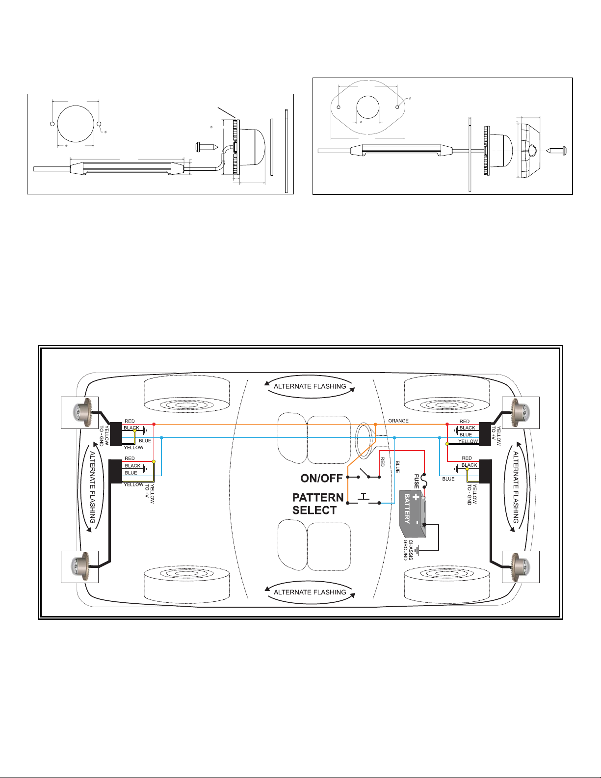
Electrical Connections:
RED: Connect to +V through an ON/OFF switch. The use of a fuse located close to the voltage source is recommended. Size the fuse according to the
number of heads used in the system. 18AWG or larger wire is recommended.
BLACK: Connect to - GROUND vehicle chassis. 18AWG or larger wire is recommended.
BLUE: Flash pattern SYNC and SELECTION wire. If you wish to have all the LED heads synchronize their ash timings and patterns with each other then all
the BLUE wires must be connected together. (64 Heads Maximum) The BLUE wire is also used to select the ash pattern. Touch the BLUE wire to +V to
select the next pattern in the FLASH PATTERN LIST. The BLUE wire can also be run to a momentary push-button located on the dashboard to allow the
ash pattern to be changed when desired. Note: Do not connect the BLUE wire to - Ground. It will disrupt the ash pattern sync signal.
YELLOW: Alternating / Simultaneous selection. Connect to either +V or GROUND (GND).
The YELLOW wire makes the head re AT THE SAME TIME or ALTERNATING with the other heads in the system.
Heads with YELLOW connected to +V re at the same time. Heads with YELLOW connected to GND re at the same time.
Heads with YELLOW connected to +V will ALTERNATE with heads that have YELLOW connected to GND.
The YELLOW wire has no function in STEADY ON mode.
INSTALLATION OF 4 HIDE-A-LED™ USING PATTERN SELECT SWITCH PANEL (OPTIONAL) ON DASHBOARD.
Operation:
After installing the system it is best to do a POWER-UP RESET the rst time to ensure that all heads are in sync. Touch BLUE wires to +V (RED wire) while
applying power. Wait 1 second and then release the BLUE wires. All heads will reset to Pattern #2. (If you have installed a pattern select pushbutton, press
and hold pattern select while turning power switch ON.) To select a ash pattern, touch BLUE to +V or press pattern select switch to increment the ash
pattern. The heads will remember the ash pattern you have selected until it is changed again. When you increment past pattern #16 it will roll back around to
pattern #1.
Flash patterns 9 to 16 in the ash pattern list run through the patterns
listed in a continuous cycle.
If you are using this product to synchronize with an older product which only has ash patterns 1 through 8 then you may program this product to limit it’s ash
pattern list. Perform the following: Connect BLUE to RED (or press and hold pattern select button if installed. Connect to power and hold for 5 seconds. The
LED head will blink 1 time to indicate it is set for the old 8 pattern set, twice to indicate the 16 pattern set.
920-0211-00 Rev. A Page 2 of 3
Page 3

# Pattern: Frequency: Description:
1 Quad Flash 1.25 Hz 75 Quad Flashes Per Minute
2 Double Flash 1.25 Hz 75 Double Flashes Per Minute
3 Triple Flash 1.53 Hz 92.3 Triple Flashes Per Minute
4 DeciBlast 1.42 Hz 85.5 Deci Flashes Per Minute
5 Single Flash 1.25 Hz 75 Single Flashes Per Minute
6 Mega Flash 1.90 Hz 114 Single Flashes Per Minute
7 Triple+Burst 1.37 Hz 82.5 Triple+Burst Flashes Per Minute
8 Steady On Steady On
9 Cycle All Cycle through patterns 1 to 7
10 Double-Triple+Burst 2 Double, 2 Triple+Burst cycle
11 Cycle Classic 1 Double, 1 Quad, 2 Mega cycle
12 Quad-Mega 3 Quad, 4 Mega cycle
13 Single-Quad 2 Single, 2 Quad cycle
14 DeciBlast-Quad 2 DeciBlast, 2 Quad cycle
15 Single-Triple-DeciBlast 2 Single, 2 Triple, 2 DeciBlast cycle
16 Mega-Triple+Burst 1 Mega, 1 Triple+Burst cycle.
Manufacturer Limited Warranty and Limitation of Liability:
TroubleShooting:
HEAD NOT FLASHING:
Check the RED and BLACK wires for a reversed connection.
(Reverse connection will not damage the unit).
Check RED and BLACK wires for either a bad splice or a corroded
ground connection.
HEADS NOT SYNCHRONIZING:
Check for a short circuit on the BLUE wire to either +V or GROUND.
Salt water on the wire connections will short circuit the sync signal on
the BLUE wire. Check for non-functional heads in the system. If any
one of the heads has a bad GROUND connection it can cause the
sync signal to become corrupted. If any one of the heads has it’s RED
and BLACK wires reverse connected it will corrupt the sync signal.
FLASH PATTERN CHANGING:
If the ash pattern changes on it’s own there may be an intermittent
short between the BLUE wire and +V. Check for water in the wiring
connections. If any one of the heads in the system has an intermittent
GROUND connection it can also cause the ash pattern to change.
Manufacturer warrants that on the date of purchase this product will conform to Manufacturer’s specications for this product (which are available from the
Manufacturer upon request), and Manufacturer further warrants that this product is free from defects in materials and workmanship. This Limited Warranty
extends for twenty-four (24) months from the date of purchase. Other warranties may apply, call Manufacturer for details. Manufacturer will, at its discretion,
repair or replace any product found by the Manufacturer to be defective and subject to this Limited Warranty.
DAMAGE TO PARTS OR PRODUCTS RESULTING FROM TAMPERING, ACCIDENT, ABUSE, MISUSE, NEGLIGENCE, UNAPPROVED MODIFICATIONS,
FIRE OR OTHER HAZARD; IMPROPER INSTALLATION OR OPERATION; OR NOT BEING MAINTAINED IN ACCORDANCE WITH THE MAINTENANCE
PROCEDURES SET FORTH IN MANUFACTURER’S INSTALLATION AND OPERATING INSTRUCTIONS VOIDS THIS LIMITED WARRANTY.
ORAL STATEMENTS OR REPRESENTATIONS ABOUT THE PRODUCT WHICH MAY HAVE BEEN MADE BY SALESPEOPLE, DEALERS, AGENTS OR
OTHER MANUFACTURER’S REPRESENTATIVES DO NOT CONSTITUTE WARRANTIES. THIS LIMITED WARRANTY MAY NOT BE AMENDED, MODIFIED, OR ENLARGED EXCEPT BY A WRITTEN AGREEMENT SIGNED BY AN AUTHORIZED OFFICIAL OF MANUFACTURER WHICH EXPRESSLY
REFERS TO THIS LIMITED WARRANTY.
Exclusion of Other Warranties:
MANUFACTURER MAKES NO OTHER WARRANTIES, EXPRESS OR IMPLIED. THE IMPLIED WARRANTIES FOR MERCHANTABILITY OR FITNESS
FOR A PARTICULAR PURPOSE ARE HEREBY EXCLUDED AND SHALL NOT APPLY TO THE PRODUCT. BUYER’S SOLE AND EXCLUSIVE REMEDY
IN CONTRACT, TORT, OR UNDER ANY OTHER THEORY AGAINST MANUFACTURER REGARDING THE PRODUCT AND ITS USE SHALL BE THE
REPLACEMENT OR REPAIR OF THE PRODUCT AS DESCRIBED ABOVE.
Limitation of Liability:
IN THE EVENT OF LIABILITY FOR DAMAGES ARISING OUT OF THIS LIMITED WARRANTY OR ANY OTHER CLAIM RELATED TO THE MANUFACTURER’S PRODUCTS, MANUFACTURER’S LIABILITY FOR DAMAGES SHALL BE LIMITED TO THE AMOUNT PAID FOR THE PRODUCT AT THE TIME
OF THE ORIGINAL PURCHASE. IN NO EVENT SHALL MANUFACTURER BE LIABLE FOR LOST PROFITS, THE COST OF SUBSTITUTE EQUIPMENT
OR LABOR, PROPERTY DAMAGE, OR OTHER SPECIAL, CONSEQUENTIAL, OR INCIDENTAL DAMAGES BASED UPON ANY CLAIM FOR BREACH OF
CONTRACT, IMPROPER INSTALLATION, NEGLIGENCE, OR OTHER CLAIM, EVEN IF MANUFACTURER OR A MANUFACTURER’S REPRESENTATIVE
HAS BEEN ADVISED OF THE POSSIBILITY OF SUCH DAMAGES. MANUFACTURER SHALL HAVE NO FURTHER OBLIGATION OR LIABILITY WITH
RESPECT TO THE PRODUCT OR ITS SALE, OPERATION AND USE, AND MANUFACTURER NEITHER ASSUMES NOR AUTHORIZES THE ASSUMPTION OF ANY OTHER OBLIGATION OR LIABILITY IN CONNECTION WITH SUCH PRODUCT.
This Limited Warranty denes specic legal rights. You may have other legal rights which vary from state to state. Some states do not allow the exclusion or
limitation of incidental or consequential damages.
833 West Diamond St
Boise, Idaho 83705
Customer Service
USA 888-844-6682
www.novawarning.com
920-0211-00 Rev. A Page 3 of 3
 Loading...