

Page 1
USER
MANUAL
vLinkTM Series
Models:
VLNK-Z3
VLNK-RLS
VLNK-U
Contents:
Introduction------------------------------------ 2
vLink Remote Mounted Antenna--------- 3
Z3 Siren Application------------------------- 6
Schematic Z3 Version--------------- 9
RLS Siren Application----------------------10
Schematic RLS Version------------13
Universal Application---------------------- -14
Schematic Unviersal Version---- 17
Connecting to vLink------------------------ 18
iOS Products------------------------ 18
Android Products------------------- 20
Customizing Settings and Security---- 23
RLS and Z3 Versions------------- 23
Universal Version------------------ 25
Specications-------------------------------26
Compliance and Approvals-------------- 27
Troubleshooting Guide-------------------- 28
Example Installations and Tips--------- 29
Warranty-------------------------------------- 30
Product Returns---------------------------- 30
IMPORTANT:
Read all instruction and warnings before installing and using.
INSTALLER: This manual must be delivered to the end user of this equipment.
Note: For more up-to-date User Manual, check C3vLink.com
Page 2
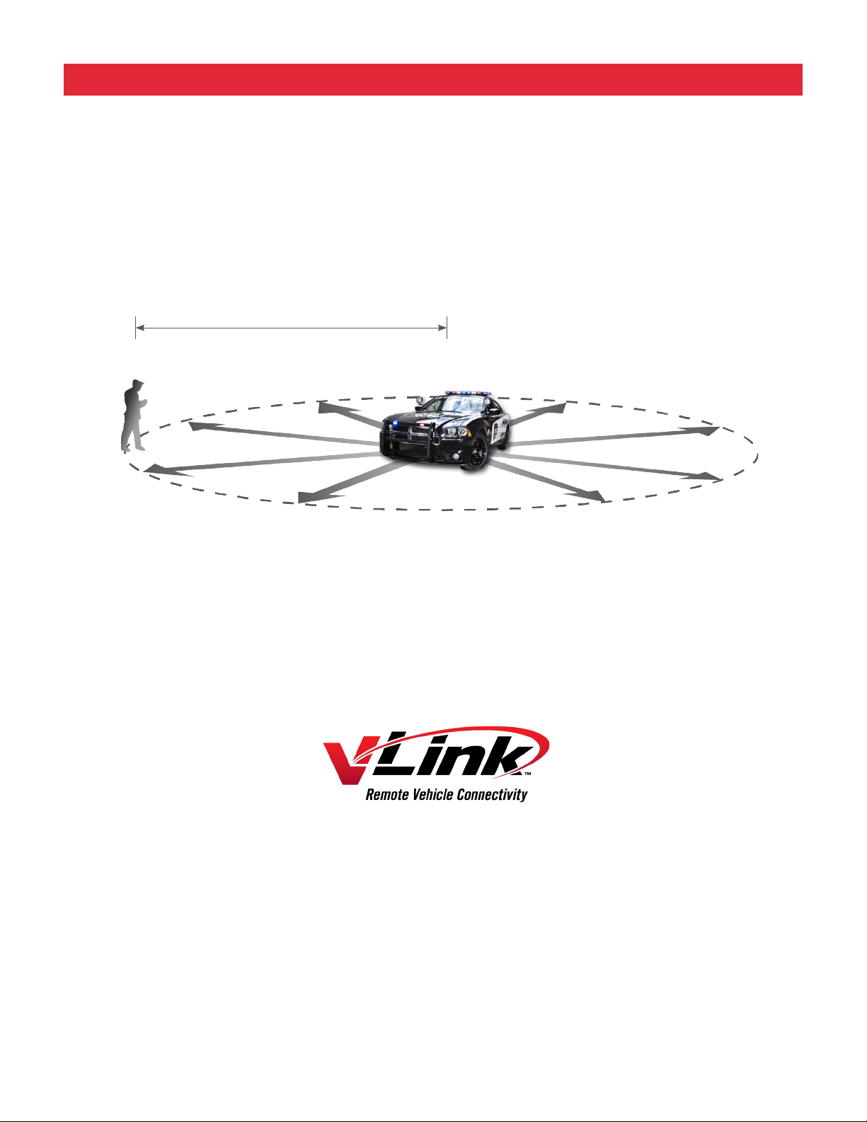
INTRODUCTION
The vLink system takes advantage of the Wi-Fi capability of your Smartphone and allows you to control your
Emergency Warning Light system up to 300 feet from the vehicle. The purpose of this document is to aid in the
setupandinstallationofthevLinksystem,andtoprovideinstructionsforitspropercongurationandoperation.
Also, refer to the Installation/User Manuals for the Z3 or RLS Siren and other products installed in conjunction
with the vLink.
range 300 feet
2
Page 3
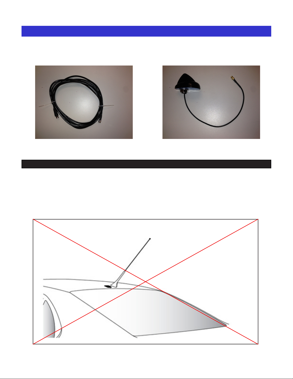
REMOTE MOUNTED ANTENNA
10’ Long ultra low loss antenna coax cable. Remote mounted antenna
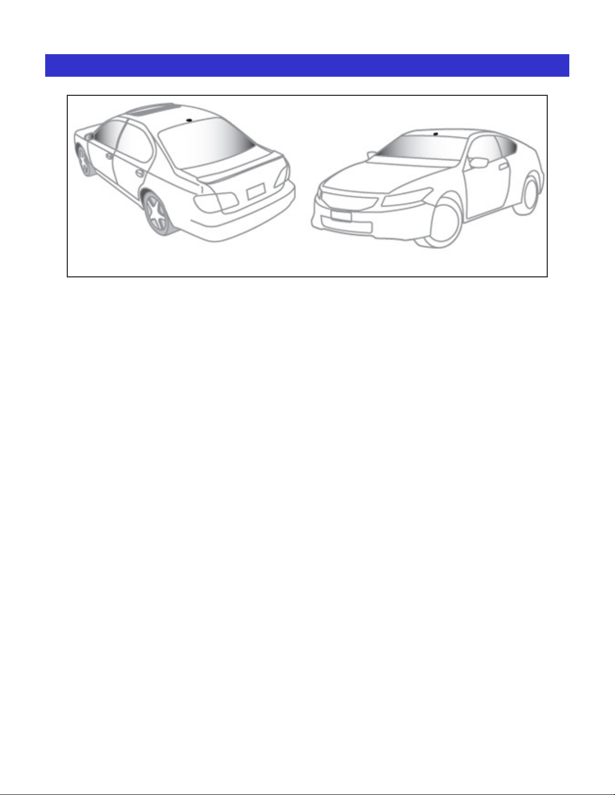
Mounting Location
For best performance, the antenna should be mounted on the roof of the car.
Select a location on the roof of the vehicle that has the fewest obstructions to the view of the antenna. The
antenna cable is 10 feet long, make sure your selected mounting location will allow you to route the cable to
the location where you plan to mount the vlink box.
Mount the antenna at least three inches away from other antennas.
3
Page 4
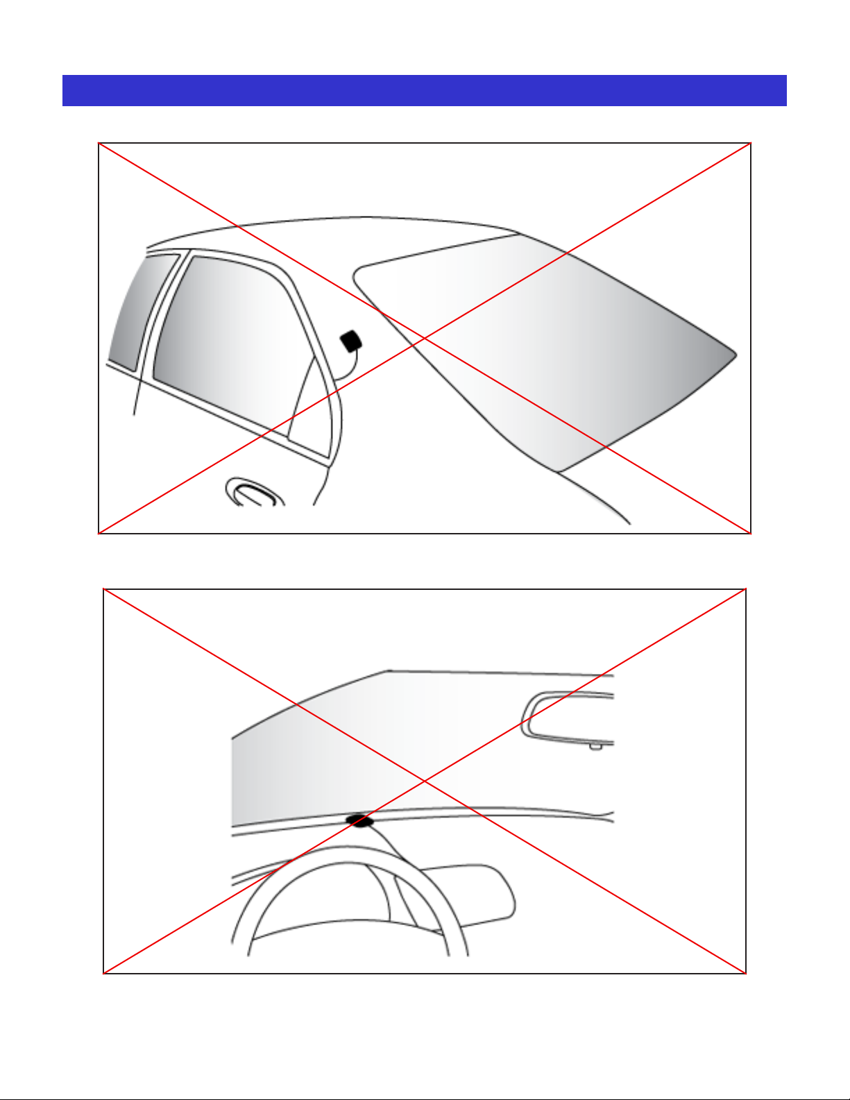
REMOTE MOUNTED ANTENNA (cont.)
Do not mount the antenna on any of the vehicle’s front, back or side
pillars.
Do not mount the antenna inside the vehicle.
4
Page 5
REMOTE MOUNTED ANTENNA (cont.)
You will need to drill a 5/8” hole in the roof at the location you selected. In order to avoid metal shavings
being left inside your headliner, place a small container inside the headliner underneath where the hole will
be drilled to catch any metal shavings.
5
Page 6
Z3 SIREN APPLICATION
Unpacking & Pre-Installation
After unpacking the vLink, carefully inspect the unit and
associated parts for any damage that may have been
caused in transit. Report any damage to the carrier
immediately.
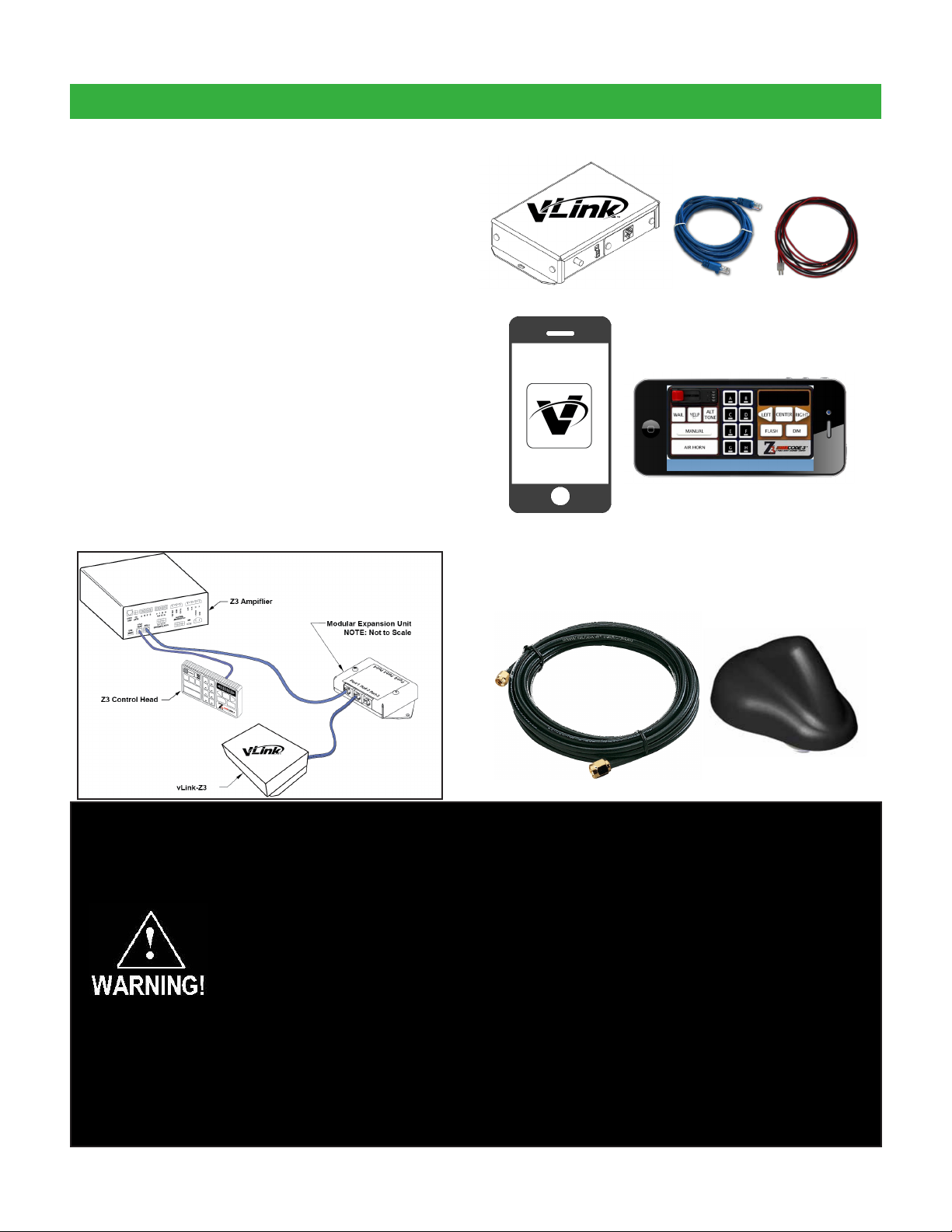
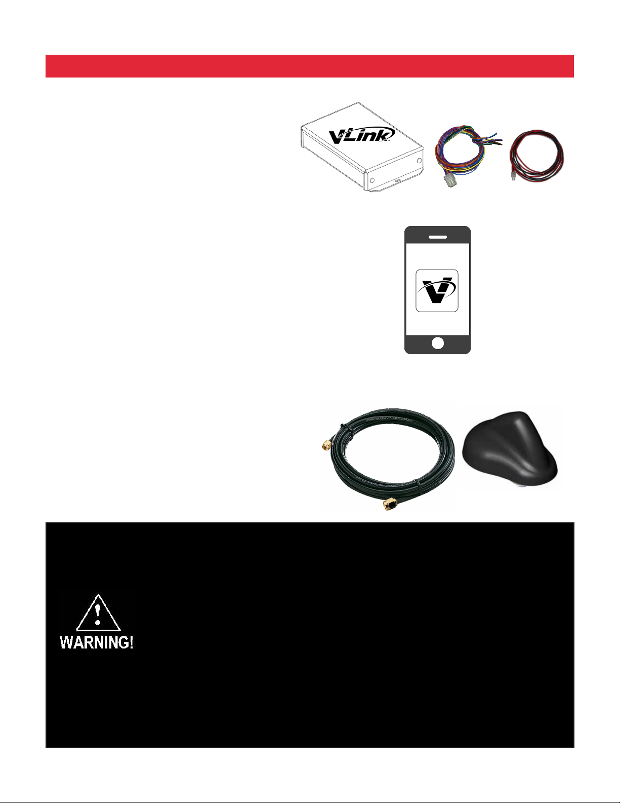
Contents of vLink™ Z3 package:
vLink Z3 controller
Communications cable
Power cable
vLink app for Z3 siren menu screen
Coax antenna cable
Remote mounted antenna
Installation & Mounting
The vLink Controller may be mounted in various
locations in the vehicle. When selecting a mounting
location, also consider the wiring requirements. Be
certain that the vLink controller is securely fastened to
the vehicle in a location that will not cause a hazard or
injury to the occupants in case of accident.
CABLE MAY LOOK
DIFFERENT
All devices should be mounted in accordance with the manufacturer's instructions and
securelyfastenedtovehicleelementsofsufcientstrengthtowithstandtheforcesapplied
to the device. Ease of operation and convenience to the operator should be the prime
consideration when mounting the siren and controls. Adjust the mounting angle to allow
maximum operator visibility. Do not mount the Hand-Held Controller in a location that will
obstruct the drivers view. Mount the Hand-Held Controller mounting base in a convenient
location to allow the operator easy access. Devices should be mounted only in locations
thatconformtotheirSAEidenticationcodeasdescribedinSAEStandardJ1849.For
example, electronics designed for interior mounting should not be placed underhood, etc.
Controls should be placed within convenient reach* of the driver, or if intended for two person
operation, the driver and/or passenger. In some vehicles, multiple control switches and/or
using methods such as “horn ring transfer” which utilizes the vehicle horn switch to toggle
between siren tones may be necessary for convenient operation from two positions.
*Convenient reach is dened as the ability of the operator of the siren system to manipulate
the controls from their normal driving/riding position without excessive movement away from
the seat back or loss of eye contact with the roadway.
6
Page 7
Z3 SIREN APPLICATION (c o n t .)
Connections
Wiring varies according to which model variant of
vLink you are installing. In all cases, +12VDC power
and system ground connections must be routed to the
location where the vLink controller will be mounted.
Using the supplied Power Cable assembly, connect
the red wire to a +12VDC Ignition Power source
that is fused at 1A. It’s important that the vLink be
powered from an Ignition switch power source so that
a Power On Reset occurs each time the vehicle is
started. Connect the black wire to vehicle ground at a
point that offers a low resistance path to the battery’s
negative terminal.
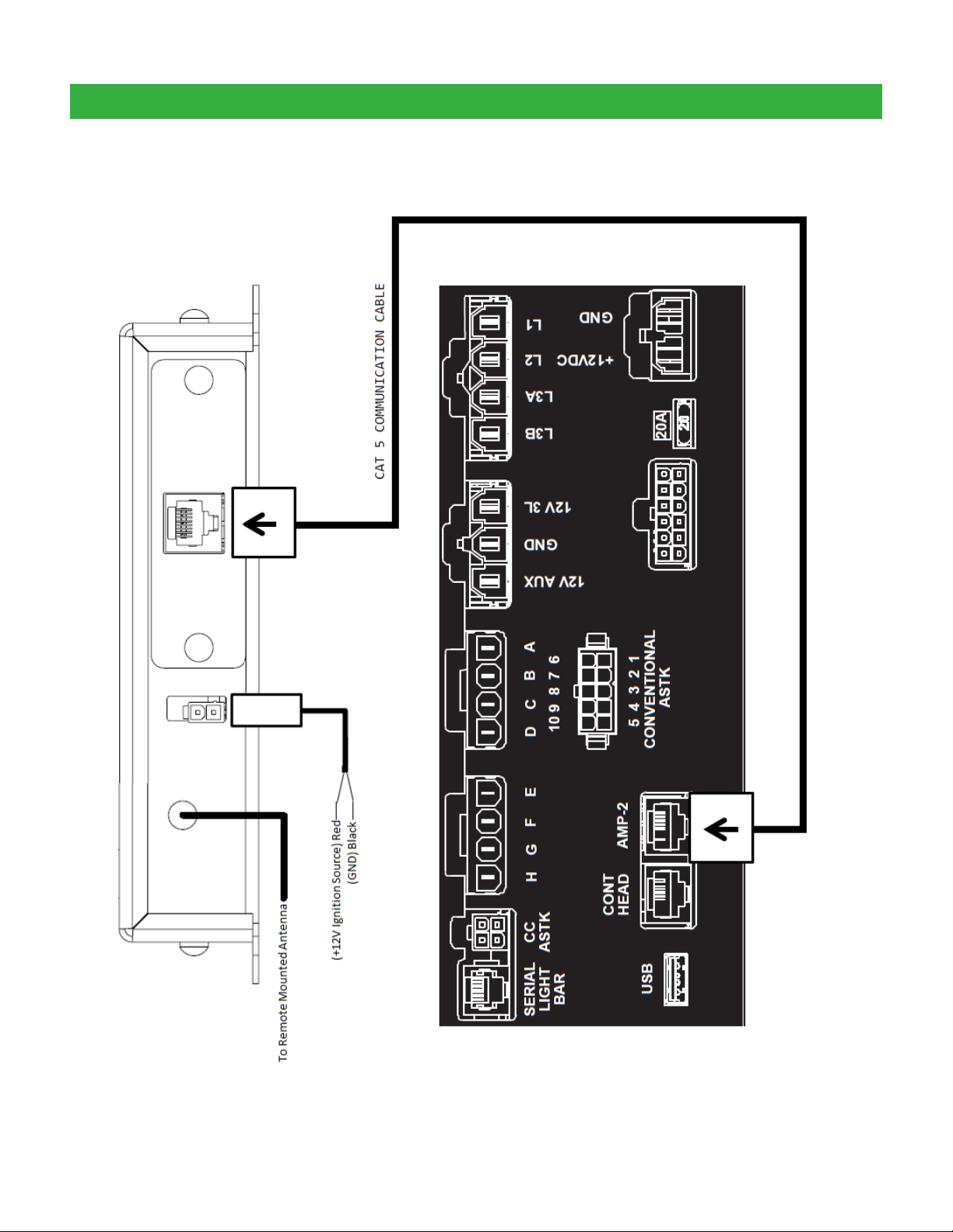
Route the control cable from the vLink Controller to
the Z3 Siren and connect per the User Manual. For
Z3 installations, route the CAT5 cable from the vLink
Controller to the Z3. Connect the CAT5 cable to the
“AMP-2” port on the Z3.
When all connections are made, turn on the vehicle’s
ignition and continue on page 18.
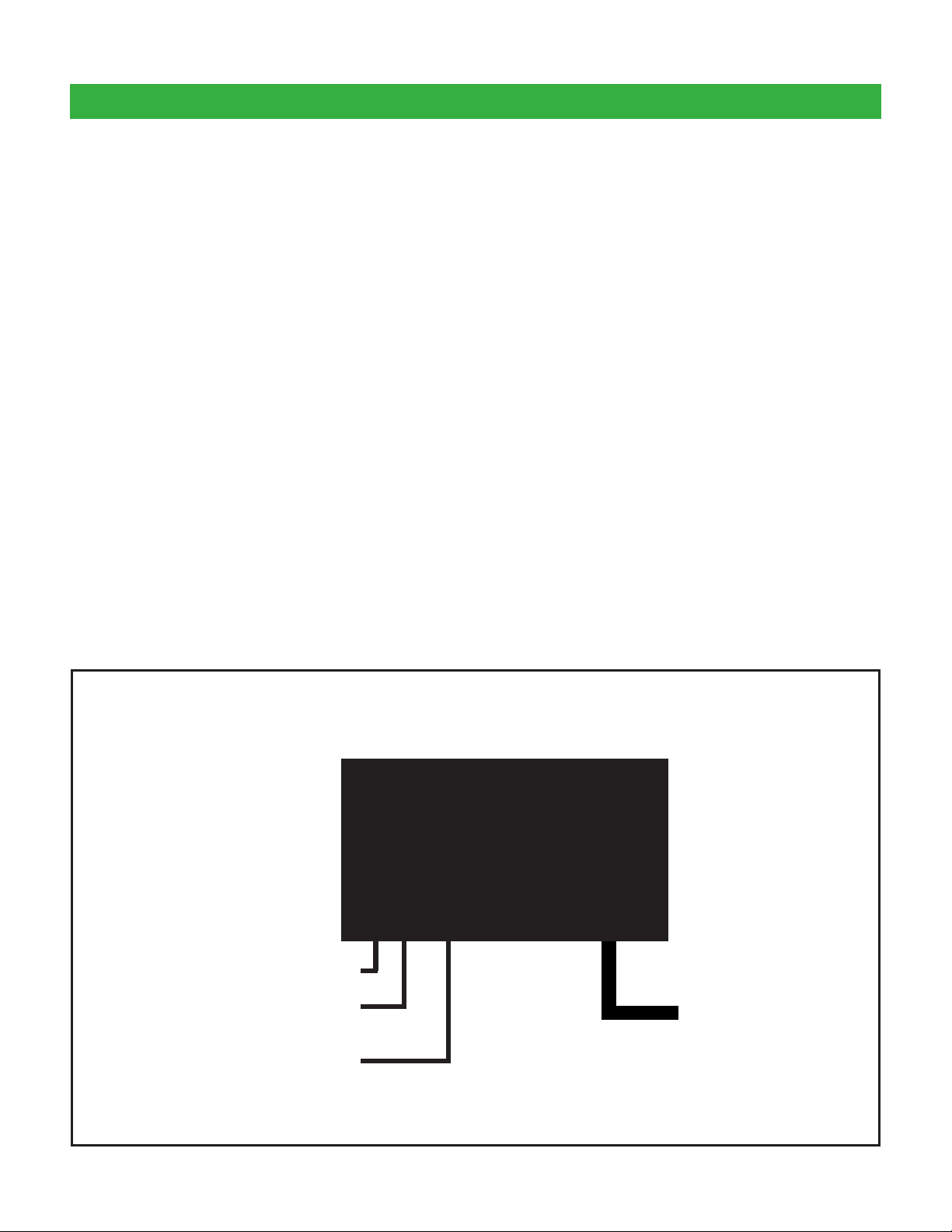
Typical Wiring for vLink-Z3
Coax Antenna Cable Connection
Ignition Switched +12VDC (fused
@ 1A)
Ground
vLink
TM
Z3 Siren Connection
(CAT 5)
7
Page 8
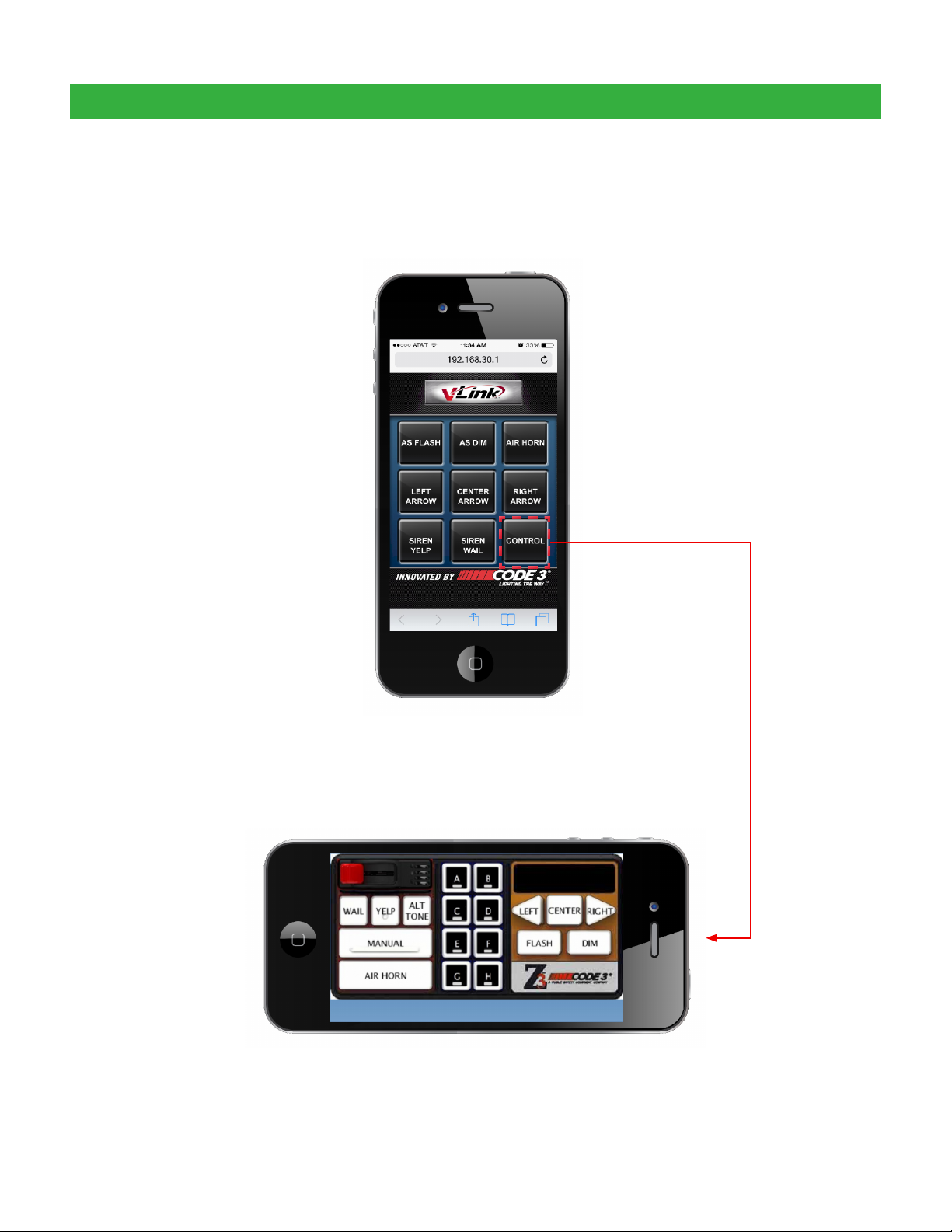
Z3 SIREN DEFAULT MENU
Z3 Default Menu Screen
Initial activation of your Z3 vLink app will show the
screen below.
Z3 Control Button
Pressing the Z3 Control button activates the
Z3 Virtual Control Head
8
continue on to page 18
Page 9
Z3 VERSION SCHEMATIC
9
Page 10

RLS SIREN APPLICATION
Unpacking & Pre-Installation
After unpacking the vLink, carefully inspect the unit and
associated parts for any damage that may have been
caused in transit. Report any damage to the carrier
immediately.
Contents of vLink™ RLS package:
vLink RLS controller
Communications cable
Power cable
vLink app for RLS siren menu screen
Coax antenna cable
Remote mounted antenna
Modular expansion unit
Installation & Mounting
The vLink Controller may be mounted in various
locations in the vehicle. When selecting a mounting
location, also consider the wiring requirements. Be
certain that the vLink controller is securely fastened to
the vehicle in a location that will not cause a hazard or
injury to the occupants in case of accident.
CABLE MAY LOOK
DIFFERENT
All devices should be mounted in accordance with the manufacturer's instructions and
securelyfastenedtovehicleelementsofsufcientstrengthtowithstandtheforcesapplied
to the device. Ease of operation and convenience to the operator should be the prime
consideration when mounting the siren and controls. Adjust the mounting angle to allow
maximum operator visibility. Do not mount the Hand-Held Controller in a location that will
obstruct the drivers view. Mount the Hand-Held Controller mounting base in a convenient
location to allow the operator easy access. Devices should be mounted only in locations
thatconformtotheirSAEidenticationcodeasdescribedinSAEStandardJ1849.For
example, electronics designed for interior mounting should not be placed underhood, etc.
Controls should be placed within convenient reach* of the driver, or if intended for two person
operation, the driver and/or passenger. In some vehicles, multiple control switches and/or
using methods such as “horn ring transfer” which utilizes the vehicle horn switch to toggle
between siren tones may be necessary for convenient operation from two positions.
*Convenient reach is dened as the ability of the operator of the siren system to manipulate
the controls from their normal driving/riding position without excessive movement away from
the seat back or loss of eye contact with the roadway.
10
Page 11
RLS SIREN APPLICATION (c o n t .)
Connections
Wiring varies according to which model variant of
vLink you are installing. In all cases, +12VDC power
and system ground connections must be routed to the
location where the vLink controller will be mounted.
Using the supplied Power Cable assembly, connect
the red wire to a +12VDC Ignition Power source
that is fused at 1A. It’s important that the vLink be
powered from an Ignition switch power source so that
a Power On Reset occurs each time the vehicle is
started. Connect the black wire to vehicle ground at a
point that offers a low resistance path to the battery’s
negative terminal.
Route the control cable from the vLink Controller to
the RLS Siren and connect per the User Manual. The
RLS installation will require the use of the RLSEXP
Modular Expansion Unit and a T11940 Modular
Cable. Route the T11940 cable from the vLink to the
PC Port on the RLSEXP. Connect the RLSEXP to the
RLS Siren using the cables provided with the kit.
When all connections are made, turn on the vehicle’s
ignition and continue on page 18.
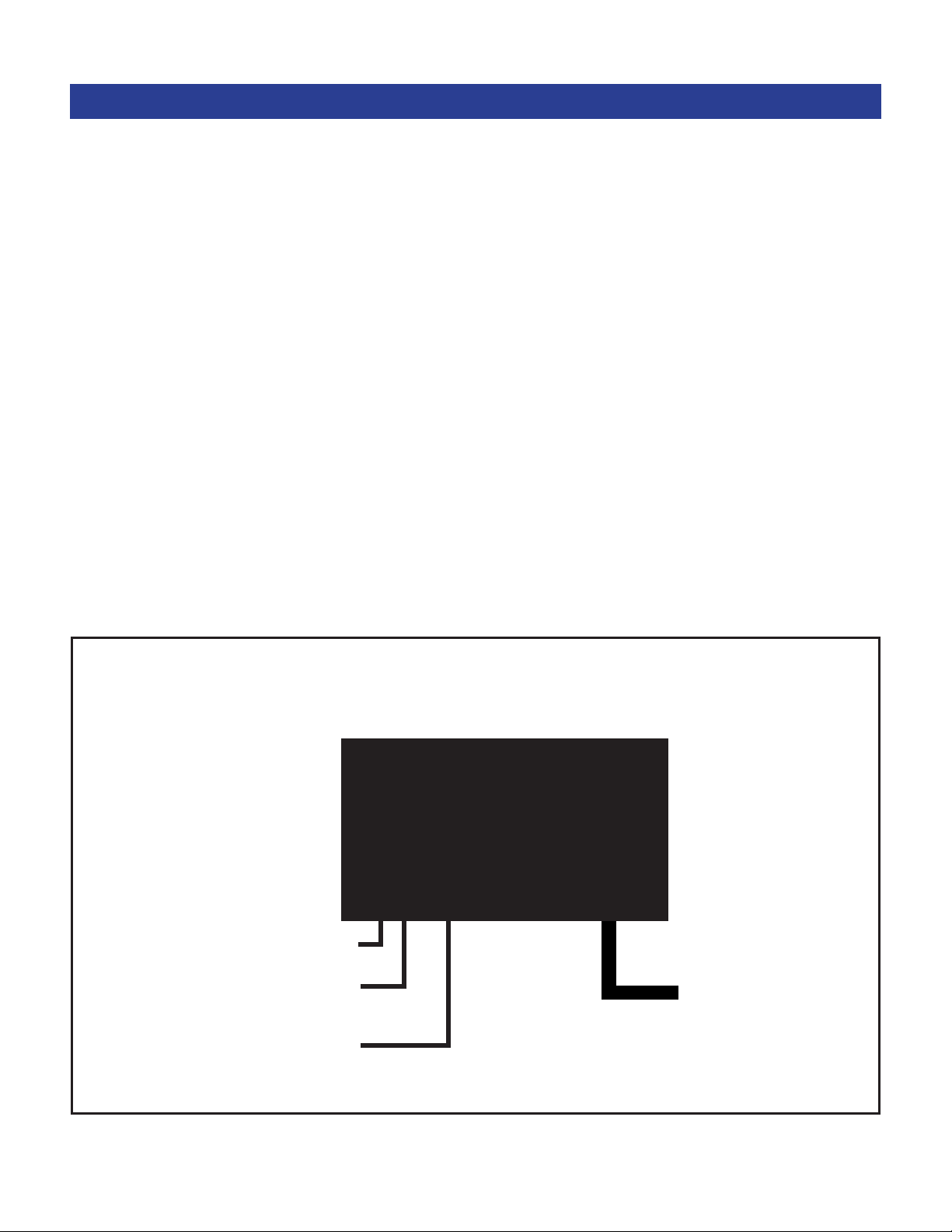
Typical Wiring for vLink-RLS
Coax Antenna Cable Connection
Ignition Switched +12VDC (fused @
1A)
Ground
vLink
TM
RLS Siren Connection
(RLSEXP PC Port)*
*RLS Modular Expansion Unit and T11940 cable required.
11
Page 12

RLS SIREN DEFAULT MENU
RLS Default Menu Screen
Initial activation of your RLS vLink app will show the
screen below.
RLS Control Button
Pressing the Control button activates the
RLS Virtual Control Head.
12
continue on to page 18
Page 13

RLS VERSION SCHEMATIC
13
Page 14
UNIVERSAL APPLICATION
Unpacking & Pre-Installation
After unpacking the vLink, carefully inspect the unit and
associated parts for any damage that may have been
caused in transit. Report any damage to the carrier
immediately.
Contents of vLink™ Universal package:
vLink Universal controller
Communications cable
Power cable
vLink app for Universal menu screen
Coax antenna cable
Remote mounted antenna
Installation & Mounting
The vLink Controller may be mounted in various
locations in the vehicle. When selecting a mounting
location, also consider the wiring requirements. Be
certain that the vLink controller is securely fastened to
the vehicle in a location that will not cause a hazard or
injury to the occupants in case of accident.
CABLE MAY LOOK
DIFFERENT
All devices should be mounted in accordance with the manufacturer's instructions and
securelyfastenedtovehicleelementsofsufcientstrengthtowithstandtheforcesapplied
to the device. Ease of operation and convenience to the operator should be the prime
consideration when mounting the siren and controls. Adjust the mounting angle to allow
maximum operator visibility. Do not mount the Hand-Held Controller in a location that will
obstruct the drivers view. Mount the Hand-Held Controller mounting base in a convenient
location to allow the operator easy access. Devices should be mounted only in locations
thatconformtotheirSAEidenticationcodeasdescribedinSAEStandardJ1849.For
example, electronics designed for interior mounting should not be placed underhood, etc.
Controls should be placed within convenient reach* of the driver, or if intended for two person
operation, the driver and/or passenger. In some vehicles, multiple control switches and/or
using methods such as “horn ring transfer” which utilizes the vehicle horn switch to toggle
between siren tones may be necessary for convenient operation from two positions.
*Convenient reach is dened as the ability of the operator of the siren system to manipulate
the controls from their normal driving/riding position without excessive movement away from
the seat back or loss of eye contact with the roadway.
14
Page 15
UNIVERSAL APPLICATION (c o n t .)
Connections
Wiring varies according to which model variant of
vLink you are installing. In all cases, +12VDC power
and system ground connections must be routed to the
location where the vLink controller will be mounted.
Using the supplied Power Cable assembly, connect
the red wire to a +12VDC Ignition Power source
that is fused at 1A. It’s important that the vLink be
powered from an Ignition switch power source so that
a Power On Reset occurs each time the vehicle is
started. Connect the black wire to vehicle ground at a
point that offers a low resistance path to the battery’s
negative terminal.
Consult lightbar user manual for applicable control
switch inputs and connect accordingly.
When all connections are made, turn on the vehicle’s
ignition and continue on page 18.
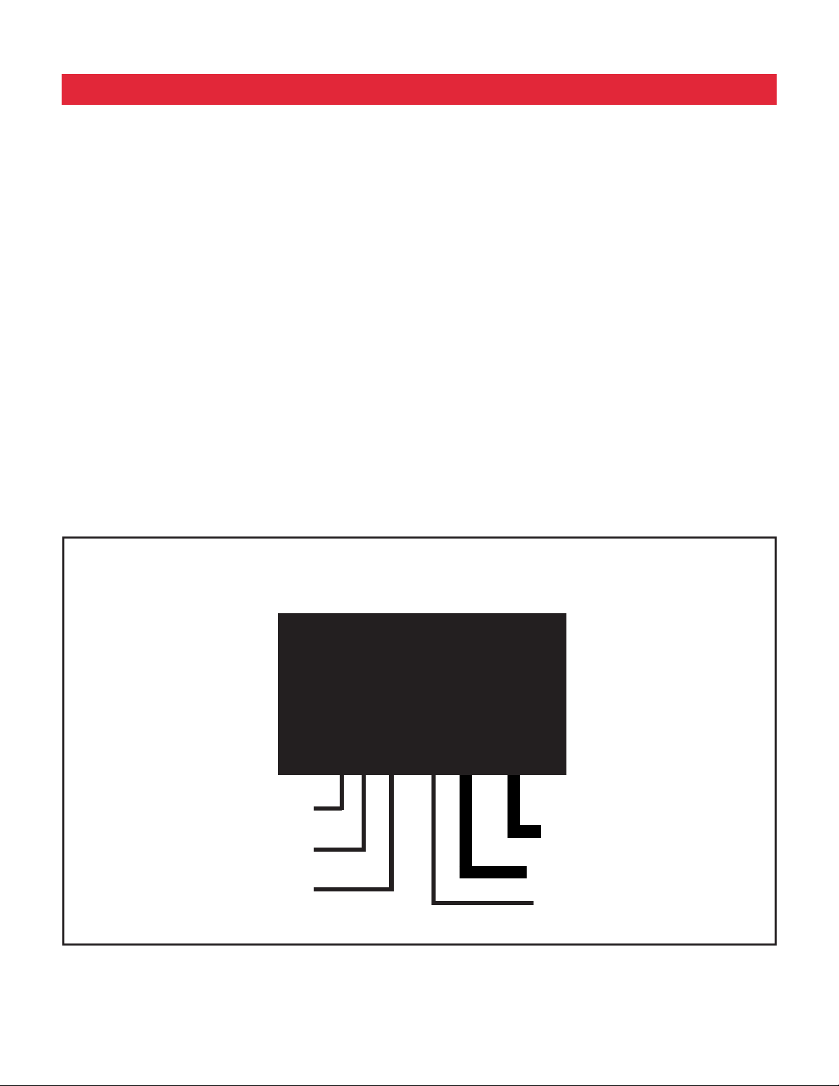
Typical Wiring for vLink-Universal
vLink
Coax Antenna Cable Connection
Ignition Switched +12VDC
(fused @ 1A)
Ground
*Route the red 10AWG wire to a high current +12VDC power source. You may extend this wire by
splicing a longer section of like wire as necessary. It’s very important that this wire be protected by a
user supplied fuse installed near the +12VDC source. The fuse rating should be about 125% of the total
current for all outputs combined but must not exceed 30A.
TM
8 Switched +12VDC Inputs
Control Switch Inputs
8 Outputs, High Side Switched
10 AWG 30 Fused Power Input*
15
Page 16

UNIVERSAL DEFAULT MENU
Initial activation of your Universal vLink app will show
Universal Default Menu Screen
the screen below.
The vLink Universal version Setup button takes you to
the settings screen as described beginning on page
20
16
continue on to page 18
Page 17

UNIVERSAL SCHEMATIC
17
Page 18

Connecting to vLink
iOS Products (iPhone and iPad)
Make sure your iPhone is upgraded to the lastest software which is currently iOS 7 and then continue with
the following steps which will show you how to connect to vLink and save the app to you home screen.
1 2 3 4
Select the Settings
application
5 6 7 8
You are now connected
to Code3CTL Press the
Home Button
Tap on Wi-Fi to view
available networks
Select the Safari
application
Tap on Code3CTL from
the list of networks
Tap on the URL entry
location
Your phone is connecting
to Code3CTL
Enter 192.168.30.1 an
then tap GO
18
Page 19

iOS Products (cont.)
9 10 11 12
Tap the center icon at the
bottom of the screen
Tap the “Add to Home
Screen” icon
Tap “Add” at the top right
of the screen
The vLink app has now
been added to your Home
Screen
PLEASE CONTINUE ON PAGE 22 TO SETUP SECURTIY FOR YOUR VLINK
AND CUSTOMIZE SETTINGS
Any electronic device may create or be affected by electromagnetic interference. After
installation of any electronic device, operate all equipment simultaneously to insure that operation
is free of interference.
19
Page 20
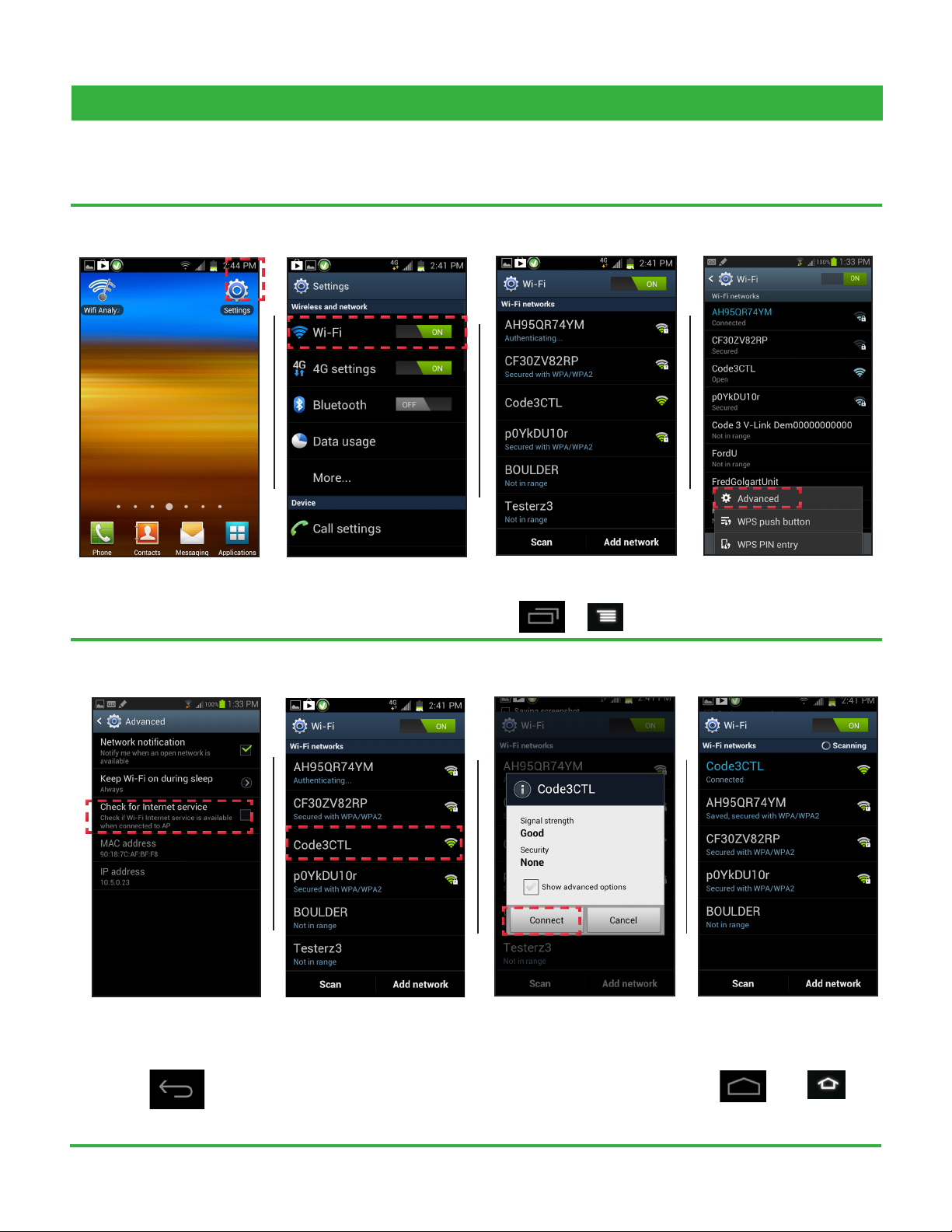
Android Products
The instructions below will take you through the necessary steps to connect to vLink and save the app to the
homescreen on your android phone.
1 2 3
Select the Settings
application
5
Tap on Wi-Fi to view
available networks
6
Select the list icon at the
bottom of your screen
7
4
Tap on advanced
8
Make sure this option is
not selected. Now hit the
back button
Tap on “Code3CTL”
20
Tap connect
You are now connected
to Code3CTL Press the
Home Button
Page 21

Android Products (cont.)
9 10 11
Select the Internet browser
application
Enter 192.168.30.1 and
then tap enter
Select the list icon at the
bottom of your screen
12
Tap “Add bookmark”
13 14 15
Tap the checkmark to save The bookmark has been
added
Tap the bookmarks icon at
the top right of your screen
16
Find the vLink bookmark
you just created. Now tap
and hold the bookmark
21
Page 22

Android Products (cont.)
17 18 19
The options list will appear.
Select “Add Shortcut to
home screen”
A shortcut has now been
added to your home
screen
Tap the vLink icon to begin
using vLink
PLEASE CONTINUE ON PAGE 23 TO SETUP SECURTIY FOR YOUR VLINK
AND CUSTOMIZE SETTINGS
Any electronic device may create or be affected by electromagnetic interference. After
installation of any electronic device, operate all equipment simultaneously to insure that operation
is free of interference.
22
Page 23

Customizing vLink Settings and Security (iOS and Android)
Z3 and RLS Versions (Z3 Version shown, RLS are congured the same)
The following instructions will take you through the steps required to setup security and make changes to vLink’s
settings.
1 2 3 4
Tap on the vLink icon
within 10 seconds of
loading to enter into
settings
5 6 7 8
Now Level Switch 1 has
been set for Button A.
Each button has a drop-
down list of available
functions. Tap the drop-
down list for button A
The change the name for
Button A, enter it into the
Name:eld.Ichosetoset
it to “LEVEL 1”
You can now see the
available functions to
select. Scroll down to
Level Switch 1.
Each button can be set as
time latched (seconds) or
momentary. Leave Timer
Delay set to 0 for regular
latched operation
Select Level Switch 1 and
then tap done.
NOTE: IMAGES TAKEN USING IPHONE, MENUS ON ANDROID DEVICES WILL LOOK DIFFERENT
Scroll down to SYSTEM
PREFERENCES.
23
Page 24

Z3 and RLS Versions (cont.)
9 10 11
If you changed the network name, go
back into Wi-Fi settings on your phone
and connect to the new name then open
the vLink app on your home screen to
start using vLink
Set a new network name
(SSID) and password. I
chose “NewName” for
the netwok name and
“NewPassword” for
password
Select submit changes
to save any changes you
may have made
NOTE: IMAGES TAKEN USING IPHONE, MENUS ON ANDROID DEVICES WILL LOOK DIFFERENT
24
Page 25
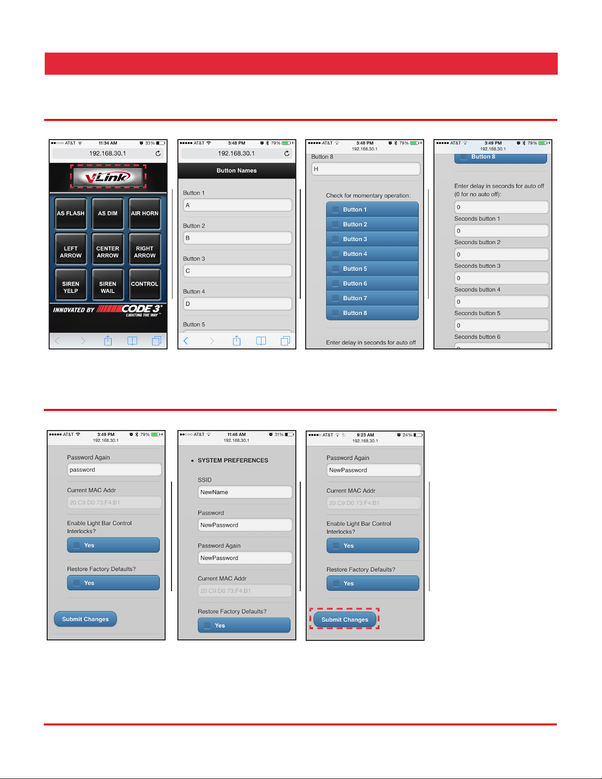
Universal version
The following instructions will take you through the steps required to setup security and make changes to vLink’s
settings.
1 2 3 4
Tap on the Settings button
on the bottom right of the
menu
5 6
Each of the 8 buttons
can be re-named by your
choosing
Each button can be set as
momentary.
7 8
Additionaly each button
can be set as time latched
(seconds). Leave timer
delay set to 0 for regular
latched operation
If you changed the
network name, go back
into Wi-Fi settings on
your phone and connect
to the new name then
open the vLink app on
your home screen to
start using vLink
NOTE: IMAGES TAKEN USING IPHONE, MENUS ON ANDROID DEVICES WILL LOOK DIFFERENT
The center row of buttons
can be set for arrowstik
operation, which only
allows one of the three
buttons to be on at a time
Set a new network name
(SSID) and password. I
chose “NewName” for
the netwok name and
“NewPassword” for
password
Select submit changes
to save any changes you
may have made
25
Page 26

Technical Specications:
Unit Weight: .84 lbs (.38 kg)
Packaged Weight: ~1.6 lbs (.8 kg)
Input Voltage: 10 to 16VDC
Operating Current: <.14 A @ 13.8VDC*
Approvals: FCC(USA),IC(Canada),ETSI(Europe)Certied
Inputs: 8**
Input Control Current: <.01A @ 13.8VDC nominal
Outputs: 8**
Output Current: 5A Max per output (30A combined total all outputs)
Dimensions:
*Excluding output load current for Universal Output version
**Universal Output version only
***Route the red 10AWG wire to a high current +12VDC power source. You may extend this wire by splicing a longer section of like wire as
necessary. It’s very important that this wire be protected by a user supplied fuse installed near the +12VDC source. The fuse rating should be
about 125% of the total current for all outputs combined but must not exceed 30A.
26
Page 27

Compliance and Approvals
Contains FCC ID: W7OMRF24WG0MAMB
This device complies with Part 15 of the FCC Rules. Operation is subject to the following two conditions:
(1) This device may not cause harmful interference, and
(2) This device must accept any interference received, including interference that may cause undesired
operation.
This equipment has been tested and found to comply with the limits for a Class B digital device, pursuant to part
15 of the FCC Rules. These limits are designed to provide reasonable protection against harmful interference
in a residential installation. This equipment generates, uses and can radiate radio frequency energy, and if not
installed and used in accordance with the instructions, may cause harmful interference to radio communications.
However, there is no guarantee that interference will not occur in a particular installation. If this equipment does
cause harmful interference to radio or television reception, which can be determined by turning the equipment
off and on, the user is encouraged to try to correct the interference by one or more of the following measures:
• Reorient or relocate the receiving antenna.
• Increase the separation between the equipment and receiver.
• Connect the equipment into an outlet on a circuit different from that to which the receiver is connected.
• Consult the dealer or an experienced radio/TV technician for help.
To satisfy FCC RF exposure requirements for mobile and base station transmission devices, a separation
distance of 20 cm or more should be maintained between the antenna of this device and persons during
operation. To ensure compliance, operation at closer than this distance is not recommended. The antenna(s)
used for this transmitter must not be co-located or operating in conjunction with any other antenna or transmitter.
Canada - Contains IC: 7693A-24WG0MAMB
TheMRF24J40MBmodulehasbeencertiedforuseinEuropeancountries.Thefollowingtestinghasbeen
completed:
Test standard ETSI EN 300 328 V1.7.1 (2006-10):
• Maximum Transmit Power
• Maximum EIRP Spectral Density
• Frequency Range
• Radiated Emissions
Test standards ETSI EN 301 489-1:2008 and ETSI EN 301 489-17:2008:
• Radiated Emissions
• Electrostatic Discharge
• Radiated RF Susceptibility
27
Page 28

Troubleshooting Guide
Problem Probable Cause Remedy
I cannot connect to my vLink. • Attempting to connect to the
wrong vLink.
• Attempting to connect to a
vLink that has the password
set.
• vLink already in use.
I start to connect, but the phone asks
me for the SSID and a password.
Each time I try to connect to vLink a
screen pops-up which says login.
During the setup process, when I
type in the IP address, the vLink main
menu (as shown in the manual) never
loads.
I have successfully completed the
setup process and tested the vLink
with my system installation, but while
demonstrating it later, I couldn’t
connect.
I have changed my vLink password
from the default “password” to
“password1” but I’ve found that others
can still join my vLink.
Even though my car is off, I can still
connect to my vLink.
When I push the air horn button, the
air horn locks on and I have to push
the button again to turn the airhorn off.
I can join the network on my VLNK-U.
Why don’t I get an output when I
energize any of the switches?
• vLink SSID and password
have been set by user.
• This is seen on the Apple
iPhone. Apple auto login
feature is set to on.
• Phone is not connected to
the vLink network.
• vLink address is being typed
wrong.
• You may not have completed
the setup process by
entering a unique password.
Under this condition, others
would be able to join your
vLink. Note: only one phone
at a time may be connected
to vLink. So, if someone else
connects to your vLink, you
will not be able to connect.
• Your unique password
cannot include any form
of the default password
“password”.
• vLink is not powered from
a switched ignition power
source.
• The air horn button is not
conguredasamomentary
switch.
• +12VDC is not connected to
the 30A input terminal
Several factors could cause this. Be
certain that you are attempting to
connect to the vLink network; in a
shop environment, check that others
within range have not connected.
SSID and password are required info
to connect. This is normal.
Go to the apple settings utility and edit
the vLink network settings by turning
off the auto login option.
Check to be certain that you are
connected to the vLink network.
Check to be sure that you are typing
the correct ip address “192.168.30.1”.
Turn the vLink OFF/ON and then
quickly connect. Once connected,
complete the setup process by
creating a unique ssid and password.
Change the SSID and password
to something that is unique and
meaningful to you.
Correct wiring connection.
Entercongurationmodeandcheck
the momentary box for the air horn
button.
Using a 10AWG wire terminated with
an appropriately sized ring terminal
and user supplied fuse, connect
+12VDC to the terminal stud on the
VLNK-U circuit board.
28
Page 29

Example Installation Photos
29
Page 30
WARRANTY
Code 3®, Inc.’s emergency devices are tested and found to be operational at the time of manufacture. Provided
they are installed and operated in accordance with manufacturer’s recommendations, Code 3®, Inc. guarantees all parts
and components (except the lamps) to a period of 1 year, LED Lighthead modules to a period of 5 years (unless otherwise
expressed) from the date of purchase or delivery, whichever is later. Units demonstrated to be defective within the warranty
period will be repaired or replaced at the factory service center at no cost.
Use of lamp or other electrical load of a wattage higher than installed or recommended by the factory, or use of
inappropriate or inadequate wiring or circuit protection causes this warranty to become void. Failure or destruction of the
product resulting from abuse or unusual use and/or accidents is not covered by this warranty. Code 3®, Inc. shall in no way
be liable for other damages including consequential, indirect or special damages whether loss is due to negligence or breach
of warranty.
CODE 3®, INC. MAKES NO OTHER EXPRESS OR IMPLIED WARRANTY INCLUDING, WITHOUT LIMITATION,
WARRANTIES OF FITNESS OR MERCHANTABILITY, WITH RESPECT TO THIS PRODUCT.
PRODUCT RETURNS
If a product must be returned for repair or replacement*, please contact our factory to obtain a Return Goods Authorization
Number (RGA number) before you ship the product to Code 3®, Inc. Write the RGA number clearly on the package near the
mailing label. Be sure you use sucient packing materials to avoid damage to the product being returned while in transit.
*Code 3®, Inc. reserves the right to repair or replace at its discretion. Code 3®, Inc. assumes no responsibility or liability for expenses incurred for the removal and /or reinstallation
of products requiring service and/or repair.; nor for the packaging, handling, and shipping: nor for the handling of products returned to sender aer the service has been rendered.
Problems or Questions? Call The Technical Assistance HOTLINE - (314) 996-2800
10986 N. Warson Road
www.code3pse.com
Code 3,® Inc., a subsidiary of
Public Safety Equipment, Inc.
iPhone is a registered trademark of Apple, Inc.
Android is a registered trademark of Google, Inc.
St. Louis, Missouri 63114-2029—USA
Ph. (314) 426-2700 Fax (314) 426-1337
Revision 0, 6/13 - Instruction Book Part No. T11892
©2013 Public Safety Equipment, Inc. Printed in USA
Code 3, Inc.
Code 3 is a registered trademark of
Code 3, Inc.
30
 Loading...