

Page 1
INSTALLATION &
OPERATION
MANUAL
IMPORTANT:
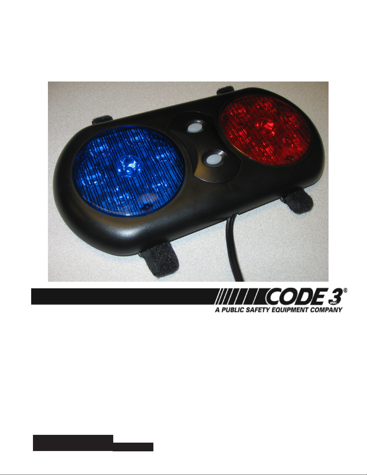
LED VISOR LIGHT
Contents:
Introduction................................................................................2
Features and Specications.....................................................2-3
Installation.................................................................................3
Synchronization.........................................................................4
Setting the Flash Pattern..............................................................4
Maintenance..............................................................................4
Troubleshooting.........................................................................4
Notes......................................................................................5-7
Warranty....................................................................................8
Read all instructions and warnings before installing and using.
INSTALLER: This manual must be delivered to the end user of this equipment.
1
Page 2
Introduction:
The LED Visor Light is a new visor mounted light that incorperates (2) PAR36 modules. The LED based warning light modules contain state-of-the-art high intensity LEDs. These products provide twenty six different
operation modes including a steady-burn mode. The LED Visor Light is SAE J595 compliant and CA Title 13
compliant when the proper ash pattern is selected (see table below).
This Product contains high intensity LED devices. To prevent eye damage, DO NOT stare
WARNING!
WARNING!
The use of this or any warning device does not insure that all drivers can or will observe or react to an emergency
warning signal. Never take the right-of-way for granted. It is your responsibility to be sure you can proceed
safely before entering an intersection, driving against trafc, responding at a high rate of speed, or walking on
or around trafc lanes.
The effectiveness of this warning device is highly dependent upon correct mounting and wiring. Read and follow
the manufacturer’s instructions before installing or using this device. The vehicle operator should insure daily that
all features of the device operate correctly. In use, the vehicle operator should insure the projection of the warning
signal is not blocked by vehicle components (i.e.: open trunks or compartment doors), people, vehicles, or other
obstructions. This equipment is intended for use by authorized personnel only. It is the user’s responsibility to
understand and obey all laws regarding emergency warning devices. The user should check all applicable city,
state and federal laws and regulations.
Code 3 , Inc., assumes no liability for any loss resulting from the use of this warning device.
Proper installation is vital to the performance of this warning device and the safe operation of the emergency
vehicle. It is important to recognize that the operator of the emergency vehicle is under psychological and physiological stress caused by the emergency situation. The warning device should be installed in such a manner as
to: A) Not reduce the output performance of the system, B) Place the controls within convenient reach of the
operator so that he can operate the system without losing eye contact with the roadway.
Emergency warning devices often require high electrical voltages and/or currents. Properly protect and use caution around live electrical connections. Grounding or shorting of electrical connections can cause high current
arcing, which can cause personal injury and/or severe vehicle damage, including re.
PROPER INSTALLATION COMBINED WITH OPERATOR TRAINING IN THE PROPER USE OF EMERGENCY
WARNING DEVICES IS ESSENTIAL TO INSURE THE SAFETY OF EMERGENCY PERSONNEL AND THE
PUBLIC.
into light beam at close range.
Features and Specications:
5 3/8” tall x 11” wide x 1” thick --- weight = 1.4 lbs
Operating Voltage: DC10V-30V, Reverse Polarity1 Protected
Flash Rate: 70 fpm minimum
Flash Modes:
PATTERN NO. PATTERNS SYNCHRONIZE
1 SINGLE FLASH 75FPM PHASE 1 YES
2 SINGLE FLASH 75FPM PHASE 2 YES
3 SINGLE FLASH 120FPM PHASE 1 YES
4 SINGLE FLASH 120FPM PHASE 2 YES
5 SINGLE FLASH 375FPM PHASE 1 YES
6 SINGLE FLASH 375FPM PHASE 2 YES
7 DOUBLE FLASH 75FPM PHASE 1 YES
2
Page 3

PATTERN NO. PATTERNS SYNCHRONIZE
8 DOUBLE FLASH 75FPM PHASE 2 YES
9 DOUBLE FLASH 130FPM PHASE 1 YES
10 DOUBLE FLASH 130FPM PHASE 2 YES
11 TRIPLE FLASH 75FPM PHASE 1 YES
12 TRIPLE FLASH 75FPM PHASE 2 YES
13 QUAD FLASH 75FPM PHASE 1 YES
14 QUAD FLASH 75FPM PHASE 2 YES
15 QUAD FLASH 150FPM PHASE 1 YES
16 QUAD FLASH 150FPM PHASE 2 YES
17 FIVE FLASH 150FPM PHASE 1 YES
18 FIVE FLASH 150 FPM PHASE 2 YES
19 QUAD FLASH 75FPM NFPA NO
20 SINGLE FLASH 75FPM, T13 NO
21 DOUBLE FLASH 75FPM, T13 NO
22 MODUFLASH SIM. NO
23 ACTION FLASH NO
24 AUTORUN (RANDOM) NO
25 STEADY BURN NO
26 OFF NO
Flashing Current Draw: Steady Burn Current Draw:
Red/Amber: .85A Avg. each lamp .85A Avg. each lamp
Blue/White: 1.0A Avg. each lamp 1.0A Avg. each lamp
Available colors - Red, Amber or Blue
Installation:
This unit is designed to be mounted on the vehicle's OEM sun visors via the adjustable attachement straps.
Wiring:
The LED Visor Light simply plugs into any standard 12/24VDC cigarette lighter socket. The plug has a 4 amp fuse
inside.
WARNING!
If the product is to be used inside the vehicle, it may cause severe personal injury if not properly
mounted and secured. Objects used in vehicle may become airborne during a collision or other
sudden changes in vehicle speed or direction, such as braking, acceleration or turns.
3
Page 4

Setting the Flash Pattern:
Push and hold either of the white oblong buttons in the center of the Visor Light as follows
- Less than 1 second for the NEXT pattern
- 1 to 3 seconds for the PREVIOUS pattern
- 3 to 5 seconds for the P13 QUAD FLASH 75FPM PHASE 1 pattern
- Greater than 5 seconds to TURN OFF the LED Light Head
Synchronization:
The (2) Par 36 lightheads in the LED Visor Light are synchronized from the factory. To congure the two lightheads to alternate their patterns, advance the pattern of either beacon to the Phase 2 mode of the current pattern. Please note that some ash patterns do no synchronize well together due to the timing required between
ash sequences. The user should visually conrm that the selected ash patterns are providing the desired
result.
Maintenance:
The LED Visor Light with PAR36 Modules is designed to be maintenance free. Refer to the guide below for
help with troubleshooting. Should the unit be diagnosed as malfunctioning, remove unit and replace with a new
module.
LED module housings may become hot with extended use. Allow modules to cool complete-
WARNING!
Problem Probable Cause Remedy
Lighthead does not activate a. No power to unit a. Check wire for loose connection
Lighthead is constantly ON a. Control wire permanently
ly before attempting to remove.
TROUBLESHOOTING
b. Power input wire reversed b. Reverse power wires
c. Damaged or shortaged cabling c. Check cables for damage
d. Defective lighthead d. Replace lighthead module
a. Avoid permanent grounding of
grounded or shorted to GND
control wire
4
Page 5

NOTES
5
Page 6

NOTES
6
Page 7

NOTES
7
Page 8

WARRANTY
Code 3, Inc.'s L.E.D. emergency devices are tested and found to be operational at the time of manufacture.
Provided they are installed and operated in accordance with manufacturer's recommendations, Code 3, Inc. guarantees
all parts and components except the lamps to a period of 1 year, LED Lighthead modules to a period of 5 years (unless
otherwise expressed) from the date of purchase or delivery, whichever is later. Units demonstrated to be defective
within the warranty period will be repaired or replaced at the factory service center at no cost.
Use of lamp or other electrical load of a wattage higher than installed or recommended by the factory, or use
of inappropriate or inadequate wiring or circuit protection causes this warranty to become void. Failure or destruction
of the product resulting from abuse or unusual use and/or accidents is not covered by this warranty. Code 3, Inc.
shall in no way be liable for other damages including consequential, indirect or special damages whether loss is due
to negligence or breach of warranty.
CODE 3, INC. MAKES NO OTHER EXPRESS OR IMPLIED WARRANTY INCLUDING, WITHOUT LIMITATION, WARRANTIES OF FITNESS OR MERCHANTABILITY, WITH RESPECT TO THIS PRODUCT.
If a product must be returned for repair or replacement*, please contact our factory to obtain a Return
Goods Authorization Number (RGA number) before you ship the product to Code 3, Inc. Write the RGA number
clearly on the package near the mailing label. Be sure you use sufcient packing materials to avoid damage to
the product being returned while in transit.
*Code 3, Inc. reserves the right to repair or replace at its discretion. Code 3, Inc. assumes no responsibility or liability for expenses incurred for the removal and /or
reinstallation of products requiring service and/or repair.; nor for the packaging, handling, and shipping: nor for the handling of products return to sender after the service has been
rendered.
Code 3 is a registered trademark of Code
3, Inc.
PRODUCT RETURNS
8
St. Louis, Missouri 63114-2029—USA
Ph. (314) 426-2700 Fax (314) 426-1337
Code 3®, Inc., a subsidiary of Public
Safety Equipment, Inc.
Revision 0, 11/09 - Instruction Book Part No. T15227
©2009 Public Safety Equipment, Inc. Printed in USA
10986 N. Warson Road
Code 3, Inc.
www.code3pse.com
 Loading...