

Page 1
INSTALLATION
& OPERATION
MANUAL
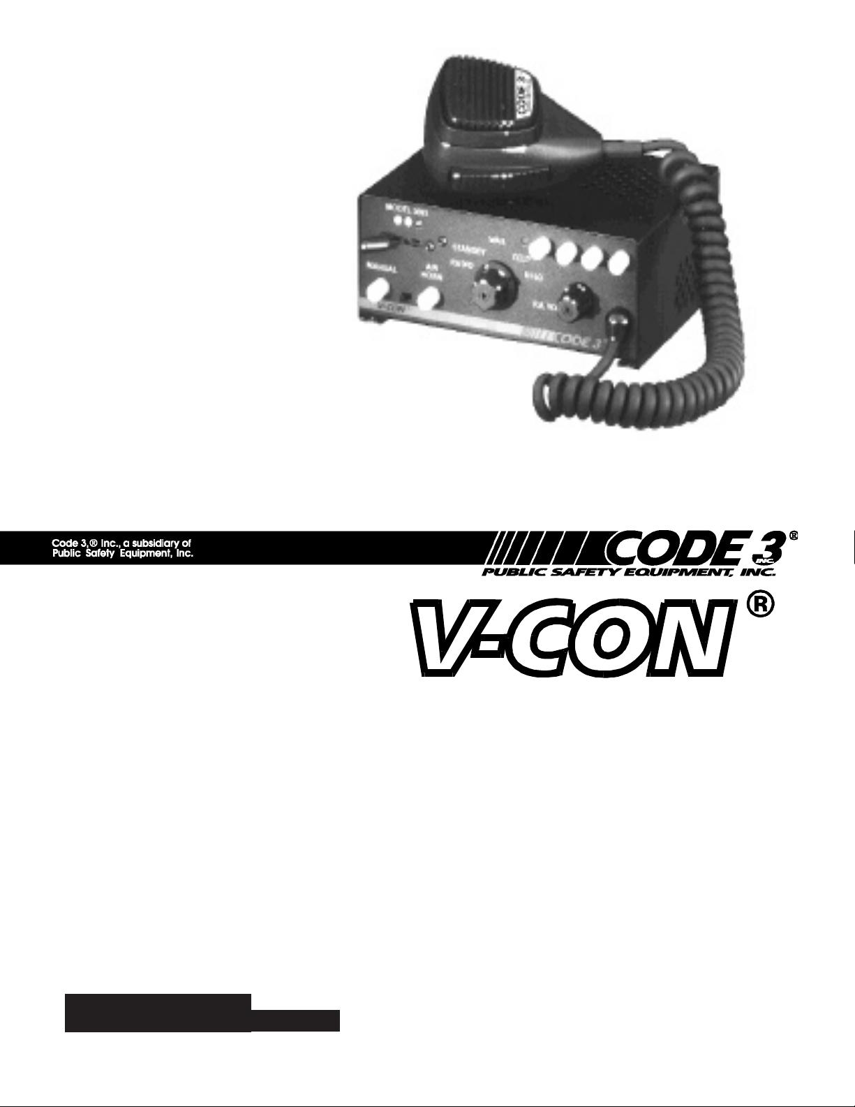
3600 SERIES SIREN
IMPORTANT:
SIRENS AND CONTROLS
Contents:
Introduction ..........................................................2
Standard Features ...............................................2
Unpacking & Pre-Installation ...............................4
Installation & Mounting ........................................4
Set-Up and Adjustment........................................7
Operation .............................................................9
Maintenance ...................................................... 11
Troubleshooting .................................................12
Parts List (Replacement Parts/Exploded View) 14
Wiring Diagram ..................................................16
Options ..............................................................17
Specications ....................................................17
Warranty ............................................................20
Read all instructions and warnings before installing and using.
INSTALLER This manual must be delivered to the end user of this equipment.
Page 2

Introduction
The 3600 series electronic siren has been designed to meet the needs of all emergency vehicles. This series of sirens incorporates
the popular packaging and features of the V-CON siren with completely new MOSFET technology. Specications are subject to
change without notice.
Sirens are an integral part of an effective audio/visual emergency warning system. However, sirens are only short
range secondary warning devices. The use of a siren does not insure that all drivers can or will observe or react
to an emergency warning signal, particularly at long distances or when either vehicle is traveling at a high rate
of speed. Sirens should only be used in a combination with effective warning lights and never relied upon as a
sole warning signal. Never take the right of way for granted. It is your responsibility to be sure you can proceed
safely before entering an intersection driving against trafc, or responding at a high rate of speed.
SIREN PRODUCTS
The effectiveness of this warning device is highly dependent upon correct mounting and wiring. Read and follow
the manufacturer’s instructions before installing this device. The vehicle operator should check the equipment
daily to insure that all features of the device operate correctly.
To be effective, sirens must produce high sound levels that potentially can inict hearing damage. Installers
should be warned to wear hearing protection, clear bystanders from the area and not to operate the siren indoors
during testing. Vehicle operators and occupants should assess their exposure to siren noise and determine what
steps, such as consultation with professionals or use of hearing protection should be implemented to protect
their hearing.
This equipment is intended for use by authorized personnel only. It is the user’s responsibility to understand
and obey all laws regarding emergency warning devices. The user should check all applicable city, state and
federal laws and regulations. Code 3, Inc., assumes no liability for any loss resulting from the use of this warning
device.
Proper installation is vital to the performance of the siren and the safe operation of the emergency vehicle. It
is important to recognize that the operator of the emergency vehicle is under psychological and physiological
stress caused by the emergency situation. The siren system should be installed in such a manner as to: A) Not
reduce the acoustical performance of the system, B) Limit as much as practical the noise level in the passenger
compartment of the vehicle, C) Place the controls within convenient reach of the operator so that he can operate
the system without losing eye contact with the roadway.
Emergency warning devices often require high electrical voltages and/or currents. Properly protect and use caution
around live electrical connections. Grounding or shorting of electrical connections can cause high current arcing,
which can cause personal injury and/or severe vehicle damage, including re.
PROPER INSTALLATION COMBINED WITH OPERATOR TRAINING IN THE PROPER USE OF EMERGENCY
WARNING DEVICES IS ESSENTIAL TO INSURE THE SAFETY OF EMERGENCY PERSONNEL AND THE
PUBLIC.
Standard Features
The 3690 series sirens consist of integrated controls and amplier in a single package with 7 circuit lighting controls available as well.
The models are as follows:
3672 - Primary Tones: Wail, Yelp, HyperYelp, Air Horn
- Secondary Tones: HyperYelp, Yelp
3692 - Primary Tones: Wail, Yelp, Hi-Lo, Air Horn
- Secondary Tones: Yelp
3696P - Air Horn, PA & Radio Rebroadcast only
3622 - Same as 3692 but 24 Volt rated
2
2
Page 3

3672L4 - Same as 3672 plus Light Controls
Horn Ring Select
Slide Switch
3-Level
Switch
Auxiliary
Switches
3692L4 - Same as 3692 plus Light Controls
3696PL - Same as 3696P plus Light Controls
1 2
A
B
C D
3
3694- Same features as 3692 with addition of a rear panel connector
to accommodate single microphone systems
3694L4 - Same as 3694 model plus Lighting Controls
The following features are standard in the 3690 series (tones and
sequences may differ by model number):
Automatic Short Circuit Protection- The siren will sense a short
circuit on the speaker terminals and automatically go to standby until
Manual/Air Horn
Push-buttons
Figure 1 - Control Panel
Rotary
Selector
Switch
PA/RRB
Volume Con-
trol
Switch
Mic Jack
the fault is removed. Once the fault is removed the siren will return to
normal operation.
Hit-n-Go Mode - Setting the slide switch (DETAIL B, 4) inside, on the V-CON amplier board toward the front panel will put the siren
in the Hit-n-Go mode. This mode will be most familiar to existing V-CON users. A seven second override is standard for all tones
when activated by the Manual button or the Remote input.See OPERATION section for details.
Siren Tones - Industry standard Wail, Yelp, and Hi-Lo tones.
AIR HORN Tone - Electronic AIR HORN sound.
Public Address - Public Address override of all siren functions when the microphone Push-to-Talk key is pressed.
Auxiliary Switch, Status LED - An indicator LED, visible on the front panel that informs the operator of the status of the A,B,C & D
Auxiliary switches (LED on indicates a switch is on).
Radio Rebroadcast - Broadcast Two-way radio reception over siren speakers. These inputs are transformer coupled to prevent loading of the radio.
Remote Siren Switching – The siren can be connected to the vehicle’s horn switch (or other user supplied switch) and remotely activates either the MANUAL or AIR HORN function (if equipped). Selection is made via the front panel slide switch.
The siren is factory set as a Tri-State input and will accept a positive (+12V) signal or a ground (earth) signal, but may be
recongured to accept a positive only signal or a ground only signal. See SET-UP AND ADJUSTMENT section for details.
Tone Priority/Manual Wail - The following tones are produced while pushing the MANUAL Push-button or triggering the user-supplied REMOTE siren switch:
Manual Wail when the MANUAL Push-button is depressed while the rotary switch is in the STANDBY position.
Yelp when the MANUAL Push-button is depressed while the rotary switch is in the WAIL, YELP, HYPERYELP or HILO position.
Noise Cancelling Microphone - Wired in microphone that is easily unplugged internally for service or replacement.
Power Distribution Section (L4 Models only) - A three level progressive switch for primary warning light system control plus 4
auxiliary switches.
3
Page 4
Unpacking & Pre-installation
After unpacking your 3690 series siren, carefully inspect the unit and associated parts for any damage that may have been caused in
transit. Report any damage to the carrier immediately.
All devices should be mounted in accordance with the manufacturer's instructions and securely fastened to vehicle
elements of sufcient strength to withstand the forces applied to the device. Ease of operation and convenience to the
operator should be the prime consideration when mounting the siren and controls. Adjust the mounting angle to allow
maximum operator visibility. Do not mount the Hand-Held Controller in a location that will obstruct the drivers view.
Mount the Hand-Held Controller mounting base in a convenient location to allow the operator easy access. Devices
should be mounted only in locations that conform to their SAE identication code as described in SAE Standard
J1849. For example, electronics designed for interior mounting should not be placed underhood, etc. Controls should
be placed within convenient reach* of the driver or if intended for two person operation the driver and/or passenger. In
some vehicles, multiple control switches and/or using methods such as “horn ring transfer” which utilizes the vehicle
horn switch to toggle between siren tones may be necessary for convenient operation from two positions.
*Convenient reach is dened as the ability of the operator of the siren system to manipulate the controls from hir
normal driving/riding position without excessive movement away from the seat back or loss of eye contact with the
roadway.
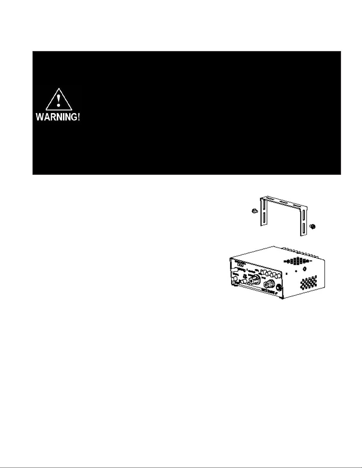
Installation & Mounting
The 3690 series siren may be mounted above the dash, below the dash, on a
tunnel or in a rack with the mounting bracket (bail) and the hardware supplied
(see Fig. 2). Ease of operation and convenience to the operator should be the
prime consideration when mounting the siren and controls.
Install the siren on the bail bracket using the 1/4-20 x 1/2" bolts and
1/4" at washers supplied. Longer bolts will prevent removal of
the chassis from the cover and may damage internal components. See Figure 2 for assembly and positioning details.
NOTE: Set-ups and adjustments will be made in subsequent steps,
depending upon the model and options purchased, that may require
access to the rear area of the unit. Plan the installation and wiring
accordingly.
Amplier Connections
Siren Amplier Connector - As a standard feature, the Siren and Auxiliary sections (L4 models) of your unit come
equipped with a screw terminal block. To terminate the wires, strip approximately 1/4" of insulation from the end of each
wire and insert it in the appropriate terminal. Tighten the screw and proceed to the next connection.
Figure 2
4
Page 5

Terminal Block Connections
8 Position Terminal Block- ( see wiring diagram page 16 )
S1 - +12VDC, connect to a positive +12 volt DC source. It is recommended that the user protect this wire with a 20 Amp
fuse or circuit breaker located at the source. Use #14 gauge wire.
S2 - GROUND, connect to the negative terminal of the battery. This supplies ground (earth) to the siren. Use #14 gauge
wire.
S3 - Speaker Common, connect to one of the wires from speaker.
S4 - 58W Speaker, connect to the remaining speaker lead for 58W speaker only.
S5 - 100/200W Speaker, connect to the remaining speaker lead for 100/200W operation (1-100W, 11 ohm speaker or
2-100W, 11 ohm speakers connected in parallel).
S6 – Remote input (Horn Ring or foot switch) is factory set as a Tri-State input (accepts a positive (+12V) signal
or a ground (earth) signal). It can be recongured to accept a positive only signal or a ground only signal. See
SET-UP AND ADJUSTMENT section for details.
S7 - RRB, connect to one side of the two-way radio speaker.
S8 - RRB, connect to the second side of the two-way radio speaker.
Larger wires and tight connections will provide longer service life for components. For high current wires it is highly
recommended that terminal blocks or soldered connections be used with shrink tubing to protect the connections.
Do not use insulation displacement connectors (e.g. 3M® ) Scotchlock type connectors). Route wiring using grommets and sealant when passing through compartment walls. Minimize the number of splices to reduce voltage
drop. High ambient temperatures (e.g. underhood) will signicantly reduce the current carrying capacity of wires,
fuses, and circuit breakers. Use "SXL" type wire in engine compartment. All wiring should conform to the minimum
wire size and otherrecommendations of the manufacturer and be protected from moving parts and hot surfaces.
Looms, grommets, cable ties, and similiar installation hardware should be used to anchor and protect all wiring.
Fuses or circuit breakers should be located as close to the power takeoff points as possible and properly sized to
protect the wiring and devices. Particular attention should be paid to the location and method of making electrical
connections and splices to protect these points from corrosion and loss of conductivity. Ground (Earth)terminations should only be made to substantial chassis components, preferably directly to the vehicle battery.
The user should install a circuit breaker sized to approximately 125% of the maximum Amp capacity in the supply
line to protect against short circuits. For example, a 30 Amp circuit breaker should carry a maximum of 24 Amps.
DO NOT USE 1/4" DIAMETER GLASS FUSES AS THEY ARE NOT SUITABLE FOR CONTINUOUS DUTY
IN SIZES ABOVE 15 AMPS. Circuit breakers are very sensitive to high temperatures and will "false trip" when
mounted in hot environments or operated close to their capacity.
5
Page 6

The speaker's sound projecting opening should be pointed forward, parallel to the ground, and not obstructed or
mufed by structural components of the vehicle. Concealed or under-hood mountings in some cases will result in a
dramatic reduction in performance. To minimize this reduction, mount the speaker so the sound emitted is projected
directly forward and obstruction by vehicle components such as hoses, brackets, grille, etc. is minimized.
Electromechanical sirens and electronic siren speakers should be mounted as far from the occupants as possible
using acoustically insulated compartments and isolation mountings to minimize the transmission of sound into the
vehicle. It may be helpful to mount the device on the front bumper, engine cowl or fender; heavily insulate the passenger compartment; and operate the siren only with the windows closed.
Each of these approaches may cause signicant operational problems, including loss of siren performance from road
slush, increased likelihood of damage to the siren in minor collisions, and the inability to hear the sirens on other
emergency vehicles.
APPROPRIATE TRAINING OF VEHICLE OPERATORS IS RECOMMENDED TO ALERT THEM TOTHESE PROBLEMS AND MINIMIZE THE EFFECT OF THESE PROBLEMS DURING OPERATIONS.
Power Distribution Connections ("L4" Models)
A #8 stud is provided on the rear of the unit and is intended for use ONLY as a convenient ground (earth) " tie-point " for
the light bar wiring. It is not an adequate ground (earth) for the siren or the light bar. It is recommended all ground
(earth) wires attached here be terminated with a crimp-on ring terminal.
11-Position Terminal Block - Lighting Control - (See Wiring Diagram page 16)
IMPORTANT!
Remember auxillary outputs A, B & D on L4 models can supply a maximum of 20 Amps each for a combined total
of 30 Amps. Install appropriate fuses in each output wire as close to the siren as possible.
T1 - SW C COM - Common or power feed for Auxiliary Switch "C". Terminals are a SPDT circuit that may be connected
as a momentary (or latching depending on the switch ordered) ignition controlled circuit, or used for switching auxiliary
circuits. It will Handle 10 Amps, and should be protected with a fuse at the battery if individually fed.
T2 - SW C NC - Connect to the load to be controlled by the normally-closed contact on Auxiliary Switch "C".
T3 - SW C NO - Connect to the load to be controlled by the normally-open contact on Auxiliary Switch "C".
T4 - AUXILIARY SW A, connect to the load to be controlled by Auxiliary Switch "A".
T5 - AUXILIARY SW B - Connect to the load to be controlled by Auxiliary Switch "B".
T6- AUXILIARY SW D - Connect to the load to be controlled by Auxiliary Switch "D".
IMPORTANT!
The total combined current for the auxillary outputs A,B & D Must not exceed 30 Amps total.
6
Page 7

T7 - +12VDC - Connect to the positive terminal of the battery with 30 Amp circuit protection. Locate the fuse or circuit
breaker at the battery and use size 10 AWG wire minimum. This terminal powers switches A,B & D only.
T8 - LEVEL 1, connect to the rst level of warning lights (Green LED) position "1" on level switch.
T9 - LEVEL 2, connect to the second level of warning lights (Yellow LED) position "2" on level switch.
T10 - LEVEL 3, connect to the third level of warning lights (Red LED) position "3" on level switch.
T11 - +12VDC - Connect to the positive terminal of the battery with 30 Amp circuit protection. Locate the fuse or circuit
breaker at the battery and use size 10 AWG wire minimum. This terminal powers the 3-Level lighting control switch only.
NOTE: LEVEL 1, LEVEL 2, LEVEL 3, switch progressively. Switch position 1 provides +12 volts at terminal T8.
Switch position 2 provides +12 volts at terminals T8 & T9. Switch position 3 provides +12 volts at terminals T8,
T9 & T10.
SET-UP AND ADJUSTMENT
Make these adjustments and position the set-up switches prior to nal mounting.
Audio Adjustments
PA/RRB Volume Adjustment - This is the main volume control located on the right side of the front panel. This control
sets the PA and RRB volume. Set the front panel volume control to the point that the PA volume from the siren speaker is
such that there is no feedback and the PA audio is intelligible.
Radio Rebroadcast Adjustment - Place the selector switch in the RADIO position. The MAX RRB trimmer located on the
rear panel of the siren and is accessible through the small hole labeled RRB. This control sets the maximum RRB level
that will reach with the front panel volume control. To adjust properly, set the volume knob fully clockwise and adjust the
RRB trimmer such that with the two-way radio volume inside the vehicle set to it's normal level, the the desired volume
level is produced outside the vehicle by the siren speaker.
Remote Input
The Remote input can be congured to activate in one of three modes: 1) Tri-State Input - accepts
a positive (+12V) signal or a ground (earth) signal, 2) Positive Only Input – accepts only a positive
(+12V) signal or 3) Ground Only Input – accepts only a ground (earth) signal. All 3600 series sirens
are factory set as a Tri-State Input. To recongure the Remote input to accept a Positive Only Input,
power up the siren while pressing the MANUAL button and holding it for approximately three (3)
seconds. When the MANUAL button is released the siren will be recongured to accept a Positive
Only Signal. To recongure the Remote input to accept a Negative Only Input, power up the siren
while pressing the AIR HORN button and holding it for approximately three (3) seconds. When the
AIR HORN button is released the siren will be recongured to accept a Negative Only Signal. To
restore the Remote input to the factory setting, power up the siren while pressing the MANUAL and
AIR HORN buttons and holding them for approximately three (3) seconds. When the MANUAL and
AIR HORN buttons are released the siren will be restored to the factory setting (Tri-State Input).
NOTE: The siren will not generate the MANUAL or AIR HORN tones during the conguration pro-
cess.
7
Page 8

Conguration Switches
1
2
3
SIRENLOCK - OFF ON
LIGHT LEVEL - 3 ONLY 2 & 3
HIT & GO - OFF ON
TO DEFEAT INDICATOR LED
FOR ANY AUXILARY SWITCH,
BREAK FOIL CORRESPONDING
TO SWITCH
A
B
C
D
A
D
B
C
Referring to DETAIL B below, gently set the Hit & Go, LightAlert and SirenLock set-up switches to the desired position. These switches are present even if the options were not purchased. If the SirenLock option was purchased and is
switched on, all of the tones except AIR HORN, are disabled until the 3-Level Warning Light Switch is moved to either the
Level-2 or the Level-3 positions.
Hit & Go - Slide the switch (#4) forward to allow the feature to operate, to the rear to defeat it.
SirenLock - The SirenLock option, when not defeated by means of the internal switches, allows siren tones (Wail, Yelp,
and Hi-Lo) to be produced only when the 3-Level Warning Light Switch is in the Lighting Level 2 (Green and Yellow LED's)
or Lighting Level 3 (Green, Yellow, and Red LED's) position. Air Horn, Radio Rebroadcast, and Public Address are unaffected by this option.
Slide the switch (#1) forward to allow the feature to operate, to the rear to defeat the feature.
To select SirenLock in level 3 only, slide the level select switch (#2) toward the rear of the siren; slide it toward the front of
the siren to enable siren tones operation in both Levels 2 and 3.
Detail B
8
Page 9

Operation
Rotary Function Selector Switch
RADIO - In the RADIO position, the audio from the 2-way radio is rebroadcast over the siren speaker. The siren tones (Wail, Yelp, &
Hi-Lo) do not operate in this position.
STANDBY - This is the standby mode. If the MANUAL button is depressed , the Manual wail tone will ramp up until it reaches a peak
then ramp down when released. If the AIR HORN button is depressed, the Air Horn sound will be produced.
WAIL - This position produces the Wail tone. Depressing the MANUAL button will now produce the Yelp tone for 7 seconds. Depressing the AIR HORN button will produce the Air Horn sound and when released will return siren to Wail tone.
"Wail" and "Yelp" tones are in some cases (such as in the state of California) the only recognized siren
tones for calling for the right of way. Ancillary tones such as "Air Horn", "Hi-Lo", "Hyperyelp", and "Hyperlo" in some cases do not provide as high a sound pressure level. It is recommended that these tones
beused in a secondary mode to alert motorists to the presence of an emergency vehicle.
YELP - This position produces the Yelp tone. Pushing the MANUAL button will continue to produce the Yelp tone. If the AIRHORN
button is pushed, the Airhorn sound will be produced and when released will return the siren to Yelp.
HI-LO - This position produces the Hi-Lo tone. Pushing the MANUAL button will now produce the Yelp tone for 7 seconds. If the
AIRHORN button is pushed, the Airhorn sound will be produced and when released will return siren to Hi-Lo.
P.A. VOLUME Knob - This control adjusts the level of the P.A. audio produced when keying the microphone and speaking into it.
This control also controls the Radio Re-broadcast level when in the " Radio " position (see SET-UP, Radio Rebroadcast Adjustment).
Push-to-Talk (PTT) Microphone Switch - Keying the microphone will automatically override whatever mode the siren is in and broadcast public address messages over the siren speaker. PTT operates in all positions of the Selector switch.
MANUAL Pushbutton Momentary Switch -Has no effect when the selector switch is in RADIO, produces the effects described above
for each selector position.
AIR HORN Pushbutton Momentary Switch (Models 3692, 3694, 3692L4 & 3694L4 only) - Produces the Air Horn tone in all selector
switch settings except RADIO.
SLIDE SWITCH (Models 3692, 3694, 3692L4 & 3694L4 only) - The slide switch located between the AIR HORN and MANUAL buttons selects the function for the REMOTE (external switch) circuitry. When the switch is to the right, the Horn Ring circuitry remotely
"depresses" the AIR HORN button and generate the AIR HORN tone. When the slide switch is to the left, it
allows the REMOTE circuitry to remotely "depress" the MANUAL pushbutton and generate the
MANUAL tone.
9
Page 10

Lighting Controls (For L4 Models Only)
WARNING LIGHTS 3-LEVEL PROGRESSIVE SLIDE SWITCH:
POSITION 1 - Supplies power to Lighting Level 1. Illuminates Green LED. Activates LightAlert if supplied
POSITON 2 - Supplies power to Lighting Levels 1 & 2. Illuminates Green and Yellow LED's. Activates LightAlert and SirenLock options if supplied.
Position 3- Supplies power to Lighting Levels 1,2, & 3. Illuminates Green, Yellow, AND Red LED's. Activates LightAlert and SirenLock
if supplied.
Auxiliary Switches:
AUXILIARY SWITCH "A" - Supplies power to the load connected to terminal SW A.
AUXILIARY SWITCH "B" - Supplies power to the load connected to terminal SW B.
AUXILIARY SWITCH "C" - Operates circuit connected to terminals SWC NO, SWC NC, SWC COM.
Functions as a latching or momentary output, depending on the type of switch installed.
AUXILIARY SWITCH "D" - Supplies power to the load connected to terminal SW D.
SirenLock - The SirenLock option, when not defeated by means of the internal switches, allows siren tones (Wail, Yelp, and Hi-Lo) to
be produced only when the Warning Light Switch is in the Lighting Level 2 (Green and Yellow LED's) or Lighting Level 3 (Green, Yel-
low, and Red LED's) position. Air Horn, Radio Rebroadcast, and Public Address are unaffected by this option.
10
Page 11

CABLE AND RECONNECT AS SHOWN ABOVE.
6 WIRE, SHIELDED CABLE (COMMON MIC ONLY)
RRB ADJUSTMENT
LIGHT BAR CABLE GROUND
S-1
20 A.
CIRCUIT
S-6
CIRCUIT (OPTIONAL)
S-8
INTERCLEAR
S-7
SPEAKER
OPTIONAL 2nd 100W
SPEAKER FOR 200W
S-5
S-3
HORN RING
S-2
BREAK MIC HI, MIC LO, & PTT WIRES IN
RADIO CONTROL HEAD TO TRANSMITTER
12 GA.
12 GA.
12 GA.
10 GA.
12 GA.
30 A.
20 A.
T-1
10 GA.
T-11
T-7
T-9, LIGHTING LEVEL 2
T-10, LIGHTING LEVEL 3
T-8, LIGHTING LEVEL 1
T-6, ACCESSORY D
T-4, ACCESSORY A
T-5, ACCESSORY B
T-3, ACCESSORY C
11
Page 12

Parts List
Ref No. Description Part No. Qty.
1 MS, #4-40 x 3/8", FLAT HD PHIL, BLK OXIDE T01101 2
2 MS, #4-40 X 1/4, RND HD, BLK OXIDE T01128 3
3 KNOB, SELECTOR T01097 1
4 KNOB, VOLUME CONTROL T01098 1
5 NUT, 3/8-32 X 1/2" X .090 T01082 3
6 FLAT WASHER, 3/8" X 0.02" T00667 3
7 KNOB, ROTARY SWITCH T01359 1
8 FACEPLATE LABEL T00664 1
MODEL 3672 T01900
MODEL 3672L4 T01901
MODEL 3692 T01337
MODEL 3692L4 T01449
MODEL 3694 T01410
MODEL 3694L4 T01453
9 MS, #6-32 X 1/4", RND HD PHIL, ZINC T01030 4
10 SCREW, #6-32 X 3/8" PAN HD T04250 2
11 TINNERMAN CLIP - #6 MS, ZINC T01058 5
12 CHASSIS FOR 3600 VCON SIREN T56436 1
13 LIGHT BOARD SUPPORT BRACKET T08640 1
14 SWITCH, 4-POSITION, LEVER T01116 1
15 MS, #8-32 X 5/8, HEX HD T00763 1
16 QUICKSLIDE, STUD MTG., 1/4" T11109 1
17 SPACER, HEAT SINK S71651 1
18 TRANSISTOR INSULATOR PAD T06363 2
19 NUT, KEP, #8-32, STEEL, ZINC T00674 2
20 SIREN AMP BOARD T11722 1
MODEL 3672 W/ WIRED MIC T11742
MODEL 3672 W/ MIC JACK T11751
MODEL 3622 W WIRED MIC T11752
MODEL 3622 W MIC JACK T11753
MODEL 3696P W/ WIRED MIC T11754
MODEL 3696P W/ MIC JACK T11755
MODEL 3692 W/ WIRED MIC T11757
MODEL 3692 W/ MIC JACK T11758
21 MS #6-32 X 3/8", PAN HD, ZINC T10290 2
22 SWITCH ACTUATOR (PUSH BUTTON) T01095 6
23 VCON RELAY BOARD 1
VCON LIGHT BOARD T55308
VCON LIGHT BOARD W/ MOM. SWITCH T55309
24 RELAY CIRCUIT BOARD INSULATOR T55318 1
25 SMS, #6 X 3/8", HEX HD T01031 1
26 SMS, #6 X 3/4", HEX HD T01169 2
27 CS 1/4-20 X 1/2", ZINC T00671 2
28 BAIL BRACKET, 7 SLOT T05389 1
29 AIR BAG DEPLOYMENT WARNING LABEL T09937 1
30 VCON COVER T05798 1
31 CHASSIS LABEL SET, USED ON ALL VCON T01454 1
32 MICROPHONE W/ PHONO JACK (OPTIONAL) T07309 1
33 MICROPHONE, HARD WIRED T07311 1
12
Page 13

1
1
2
2
2
3
4
5
5
5
6
6
6
7
8
9
9
9
9
10
10
25
11
11
11 11
11
12
13
14
15
16
17
18
18
19
19
20
21
21
22
22
22
22
24
26
26
27
27
28
29
30
31
32
33
23
EXPLODED VIEW
13
Page 14

Options
SirenLock TM (L4 and L6 Models Only)- An interlock circuit between the siren and the light control circuits that permits automatic siren
tones only when the progressive switch is in Level 3 or in Level 2 or 3 (user selectable - works in conjunction with the horn transfer
relay). This feature is used in jurisdictions that
require warning lights to be on before the siren is activated.
InterClear® This unique feature can be used to activate additional warning lights for 7 seconds when in an Hit-N-Go override or "
scrolling " by pushing a single button or the vehicle horn ring, thus allowing an additional level of warning in situations such as intersections without the operator having to take his hands off the wheel or his eyes off the road.
Pluggable Microphone - A plug-in microphone jack in lieu of the standard wired-in microphone may be specied. A plug-in noise-
canceling microphone must be ordered seperately if needed.
Specications
Siren Section
Input Voltage - 10 to 16 VDC, negative ground (earth).
(Note: Operation above 14 VDC for an extended period of time may result in speaker damage.)
Operating Current: 5 Amps @ 13.6V with 19-ohm load ( 58 W Spkr )
8 Amps @ 13.6V with 11-ohm load ( 1 - 100 W Spkr )
16Amps @ 13.6V with 5.5-ohm load ( 2 - 100 W Spkrs )
Standby Current: 18 mA excluding backlighting
Cycle Rate: WAIL - 11 cycles/minute.
YELP - 200 cycles/minute.
Voltage Output ( approx. ) 64 V peak-to-peak
Audio Section
Audio Response: 3 dB down points - 500 to 3000 hz.
1000 hz. 0 dB Reference
Audio Distortion: 10% or less below clipping.
Lighting Section ("L4" Models Only)
Warning Light Control: Progressive switching, 3 levels
30 Amps. maximum combined total for Levels 1,2 & 3
Level 1 30A maximum
Green LED Indication
Level 2 30A maximum
Yellow LED Indication
Level 3 30A maximum
Red LED indication.
14
Page 15

Auxiliary Controls A, B, C, D switches
TO TERMINAL T-9/
LIGHTING LEVEL-2
TO VEHICLE HORN
TO TERMINAL S-6
WIRING DIAGRAM, CODE 3 HORNTR, HORN RING
30
CONTROLS HORN
RING TRANSFER
LIGHTING LEVEL 2
86
TRANSFER KIT
87
85
HORN RING
ALTERNATE HORN RING TRANSFER METHOD
"C" CONTROLS HORN
ACCESSORY SWITCH
VEHICLE HORN
HORN RING
RING TRANSFER
T-1
T-2
T-7
S-6
T-3
TO BATTERY
A,B, C & D switches are latching, Push-on/off (standard), may be ordered as momentary
Independent circuits
30 Amps. maximum combined total for switches A,B & D
20 Amps. maximum load for any single output A,B, C, or D
Audible alarm (optional)
15
Page 16

TROUBLESHOOTING
(Refer to wiring diagram page 20)
PROBLEM
NO SIREN OUTPUT.
EXTERNAL 20A
FUSE BLOWS.
NO OUTPUT FROM
SPEAKER, TONES
HEARD INSIDE
AMP. MODULE.
SIREN TONES
VOLUME TOO
LOW/GARBLED.
PROBABLE CAUSE
A. SHORTED SPEAKER OR SPEAKER
WIRES. SIREN IN OVER CURRENT PROTECTION MODE.
A. AMPLIFIER POWER WIRES REVERSED
POLARITY
A. SPEAKER NOT CONNECTED/ OPEN
CIRCUIT IN SPEAKER WIRING
B. DEFECTIVE SPEAKERS
A. LOW VOLTAGE TO SIREN AMPLIFIER
B. HIGH RESISTANCE IN WIRING/DEFECTIVE SPEAKER
C. SPEAKERS PHASED IMPROPERLY
REMEDY
A. CHECK CONNECTIONS
A. CHECK POLARITY
B. REPLACE SPEAKER(S)
A. CHECK SPEAKER WIRING
B. REPLACE SPEAKER(S)
A. CHECK WIRING FOR BAD
CONNECTIONS/ CHECK VEHICLE CHARGING SYSTEM
B. CHECK SPEAKER(S) WIRING/REPLACE SPEAKER(S)
C. REFER TO PAGE 5 FOR
PROPER PHASING
HIGH RATE OF
SPEAKER FAILURE.
SIREN CONTINUES
TO OPERATE FOR
7 SEC. AFTER
MANUAL BUTTON/
HORN RING IS RELEASED.
INTERCLEAR WILL NOT
POWER AUXILIARY DEVICES.
P.A. VOLUME LOW OR NO
P.A. AT ALL. VOLUME CONTROL FULLY CLOCKWISE.
A. VEHICLE BATTERY VOLTAGE TOO HIGH
B. 58 WATT SPEAKER CONNECTED TO 100
WATT TERMINAL.
A. "HIT-N-GO" FEATURE ENGAGED. NORMAL OPERATION
A. THERE IS A SHORT IN THE WIRING, OR
THE LOAD IS GREATER THAN 1 A.
A. DEFECTIVE MICROPHONE
B. MICROPHONE NOT COMPLETELY
PLUGGED IN.
C. COMMON MICROPHONE CIRCUIT NOT
PROPERLY WIRED.
D. INCORRECT MICROPHONE.
A. CHECK VEHICLE CHARGING SYSTEM
B. USE CORRECT SPEAKER
C. CHECK TERMINALS
A. CHECK FOR SHORTS. INSTALL INTERCLEAR BOOSTER KIT (PART #INTBS)
A. REPLACE MICROPHONE
B. PLUG MICROPHONE IN
SECURELY
C. CHECK WIRING
D. CALL PSE FOR LIST OF
ADAPTABLE MICROPHONES
16
Page 17

PROBLEM
PROBABLE CAUSE
REMEDY
RRB VOLUME LOW, OR NO
RRB AT ALL. VOLUME CONTROL FULLY CLOCKWISE.
SIREN SOUNDS BY ITSELF
POWER DISTRIBUTION SECTION NOT WORKING
SIREN RUNS PROPERLY
BUT SHUTS DOWN WHILE
RUNNING, THEN STARTS
RUNNING AGAIN AFTER A
FEW MINUTES
A. MAXIMUM RADIO REBROADCAST TRIMMER MIS-ADJUSTED
B. RRB WIRES NOT CONNECTED TO TWOWAY RADIO EXTERNAL SPEAKER
A. REMOTE SWITCH (HORN RING) WIRING
FROM TERMINAL REMOTE SHORTING TO
POSITIVE OR TO GROUND (EARTH).
A. SUPPLY FUSE OPEN
B. SIREN TERMINAL NEGATIVE NOT
GROUNDED
A. VEHICLE CIRCUIT BREAKERS NOT RATED PROPERLY, AND ARE OVERHEATING,
OR ARE NOT FUNCTIONING PROPERLY
A. REFER TO SET-UP AND
ADJUSTMENT SECTION
B. CHECK RRB CONNECTIONS
A. CHECK WIRING FOR
ANY SHORTING.
A. REPLACE FUSE.
B. RECONNECT TERMINAL
NEGATIVE TO GROUND.
A. REFER TO SPECIFICATIONS SECTION, PAGE 18.
USE A BREAKER WITH 1.25x
THE AMPERAGE RATING
FOR THE WATTAGE BEING
USED.
17
Page 18

NOTES
18
Page 19

NOTES
19
Page 20

WARRANTY
Code 3, Inc.'s emergency devices are tested and found to be operational at the time of manufacture. Provided
they are installed and operated in accordance with manufacturer's recommendations, Code 3, Inc. guarantees all parts
and components except the lamps to a period of 1 year (unless otherwise expressed) from the date of purchase or
delivery, whichever is later. Units demonstrated to be defective within the warranty period will be repaired or replaced
at the factory service center at no cost.
Use of lamp or other electrical load of a wattage higher than installed or recommended by the factory, or use
of inappropriate or inadequate wiring or circuit protection causes this warranty to become void. Failure or destruction
of the product resulting from abuse or unusual use and/or accidents is not covered by this warranty. Code 3, Inc.
shall in no way be liable for other damages including consequential, indirect or special damages whether loss is due
to negligence or breach of warranty.
CODE 3, INC. MAKES NO OTHER EXPRESS OR IMPLIED WARRANTY INCLUDING, WITHOUT LIMITATION, WARRANTIES OF FITNESS OR MERCHANTABILITY, WITH RESPECT TO THIS PRODUCT.
PRODUCT RETURNS
If a product must be returned for repair or replacement*, please contact our factory to obtain a Return
Goods Authorization Number (RGA number) before you ship the product to Code 3, Inc. Write the RGA number
clearly on the package near the mailing label. Be sure you use sufcient packing materials to avoid damage to
the product being returned while in transit.
*Code 3, Inc. reserves the right to repair or replace at its discretion. Code 3, Inc. assumes no responsibility or liability for expenses incurred for the removal and /or
reinstallation of products requiring service and/or repair.; nor for the packaging, handling, and shipping: nor for the handling of products return to sender after the service has been
rendered.
PROBLEMS OR QUESTIONS? CALL OUR TECHNICAL ASSISTANCE HOTLINE (314) 996-2800
St. Louis, Missouri 63114-2029—USA
Ph. (314) 426-2700 Fax (314) 426-1337
10986 N. Warson Road
www.code3pse.com
Code 3, Inc.
Code 3 is a registered trademark of Code 3, Inc. a subsidiary of Public Safety Equipment, Inc.
Revision 0, 07/10 - Instruction Book Part No. T55363
©2010 Public Safety Equipment, Inc. Printed in USA
 Loading...