

Page 1
INSTALLATION &
OPERATION
MANUAL
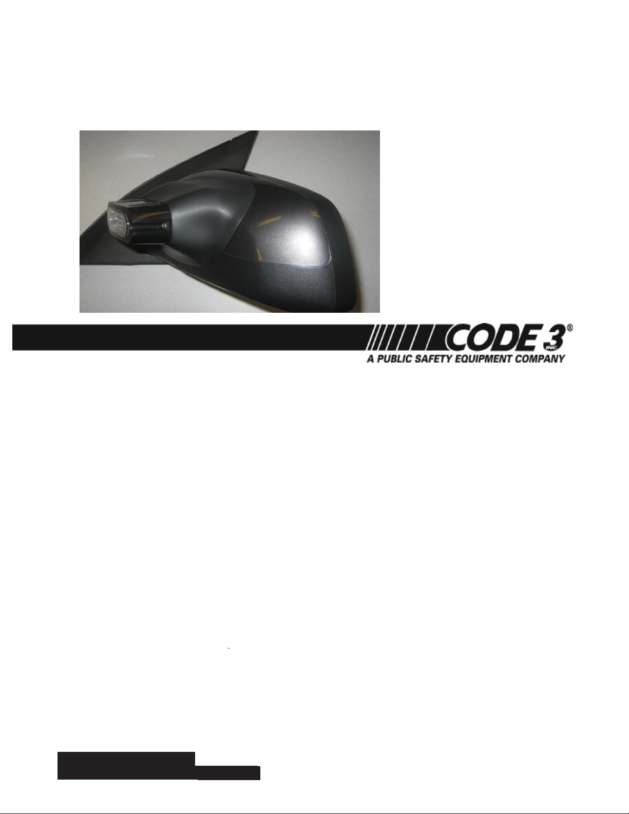
(2011 Caprice Shown)
NEW FOR
'2011'
ONE ASSEMBLY FITS
DRIVER & PASSENGER
SIDES ON THE
FOLLOWING VEHICLES:
1. CHEVROLET CAPRICE
2. CHEVROLET TAHOE
3. CHEVROLET IMPALA
4. FORD NGPI
5. FORD UTILITY INTERCEPTOR
6. FORD EXPLORER
7. FORD EXPEDITION
8. FORD CROWN VICTORIA
9. DODGE CHARGER
(Plus More!)
UNIVERSAL
OUTSIDE MIRROR MOUNTING
SYSTEM AND ALL-WEATHER
COVER FOR T-REX™ EXTERIOR
LED LIGHTS
TABLE OF CONTENTS:
PAGE: DESCRIPTION:
2. Placement of lighthead to mirror
2. Installation of Mounting System to mirror
3. Cable wiring routing and connections
4. Light head preparation
5. Final installation steps
6. Parts list & exploded view
7. Installation examples & extended bracket use
8. Warranty Information
(patent pending)
IMPORTANT:
IMPOR-
Read all instructions and warnings before installing and using.
This manual must be delivered to the end user of this equipment.
INSTALLER:
INSTALLER:
1
Page 2
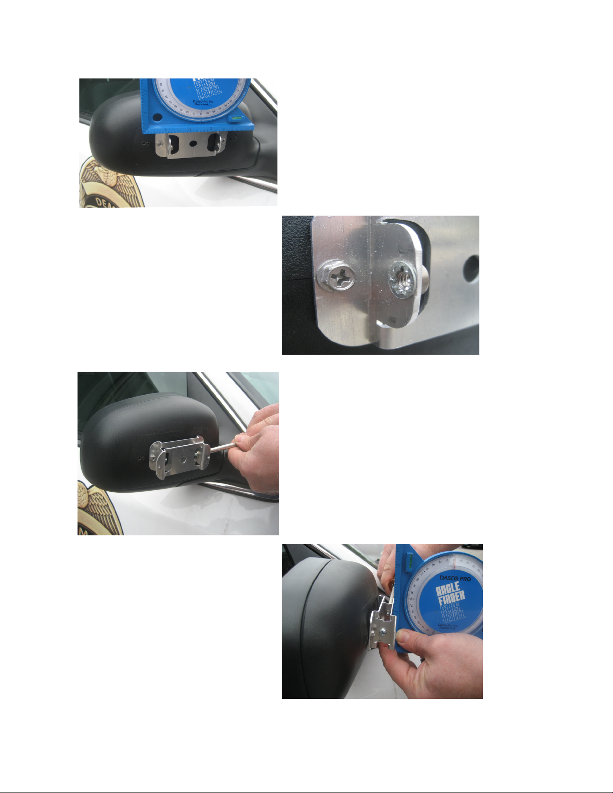
Vehicle must be parked on level surface during installation
Step 1. Select mounting area
and drill 1/2" dia. cable hole
into center of area.
Align Horizontally on mirror
housing using level as shown.
Step 2. secure lower
mounting bracket to
mirror housing using (2)
star washers and self taping S.S. screws supplied
Step 4. Align Vertically
by placing level across
face of pivot bracket
as shown, then tighten
screws on ends of pivot
bracket
Step 3. Attach pivot bracket
to mounting bracket, making
sure to place star washer between bracket faces as shown.
(a small amount of adhesive can be
used to hold star washer in place if de-
sired during assembly)
(Do not tighten until step 4)
2
Page 3
Wiring Installation:
1. Use 11" wire tie wrap included in kit as a wiring snake for installing cable
through mirror housing.
2. Cut off the clinching end of the wire tie and discard (g 1)
3. Using electrical tape, tightly wrap the cable to the wire tie (2-3 inches along
cable. (g 2 & g 3)
4.Push wire tie end through wireways between the door jam connection and the
mirror mounting locations in the assembly.
5. Depending on the model of vehicle being installed on, the mirror assmbly may
need to be removed from the door in order to feed wiring through the OEM wire
path and into the vehicle interior. Some models are easier to feed from the
door attaching point into the mirror rather than from the mirror inward.
6. Refer to the vehicle wiring guide to determine proper routing and interface for
the light head assembly being installed.
7. Refer to the T-Rex LED light head installation manual to determine setting of
(4) ash patterns available.
Wire functions:
a. Red- Power
b. Black- Ground
c. White- Pattern
d. Purple- Syncronization
g 1
g 3
g 2
3
Page 4

Light head preparation:
1. Feed wires from light head through to inside of rubber cover (g 4)
2. Terminate cable ends under pivot bracket on mirror assembly (g 5) using either the male
or female quick slide connectors supplied.
3. Feed wires from light head through or over the pivot bracket and terminate light head
assembly under pivot bracket using quick slide connectors of the opposite type used on the
cable assemblysupplied in mounting kit.
4. Mate connectors such that Power is to the Red wire from the light head, Black to ground
and either Purple for syncronization, or White for pattern selection to the third wire provided.
(g. 6)
4. Tuck wire connectors under mounting bracket assembly and proceed with cover
installation as shown. (g 7)
5. Proceed with installation in Step 5- page 5 of installation manual.
g 4
g 5
g 7
g 6
4
Page 5
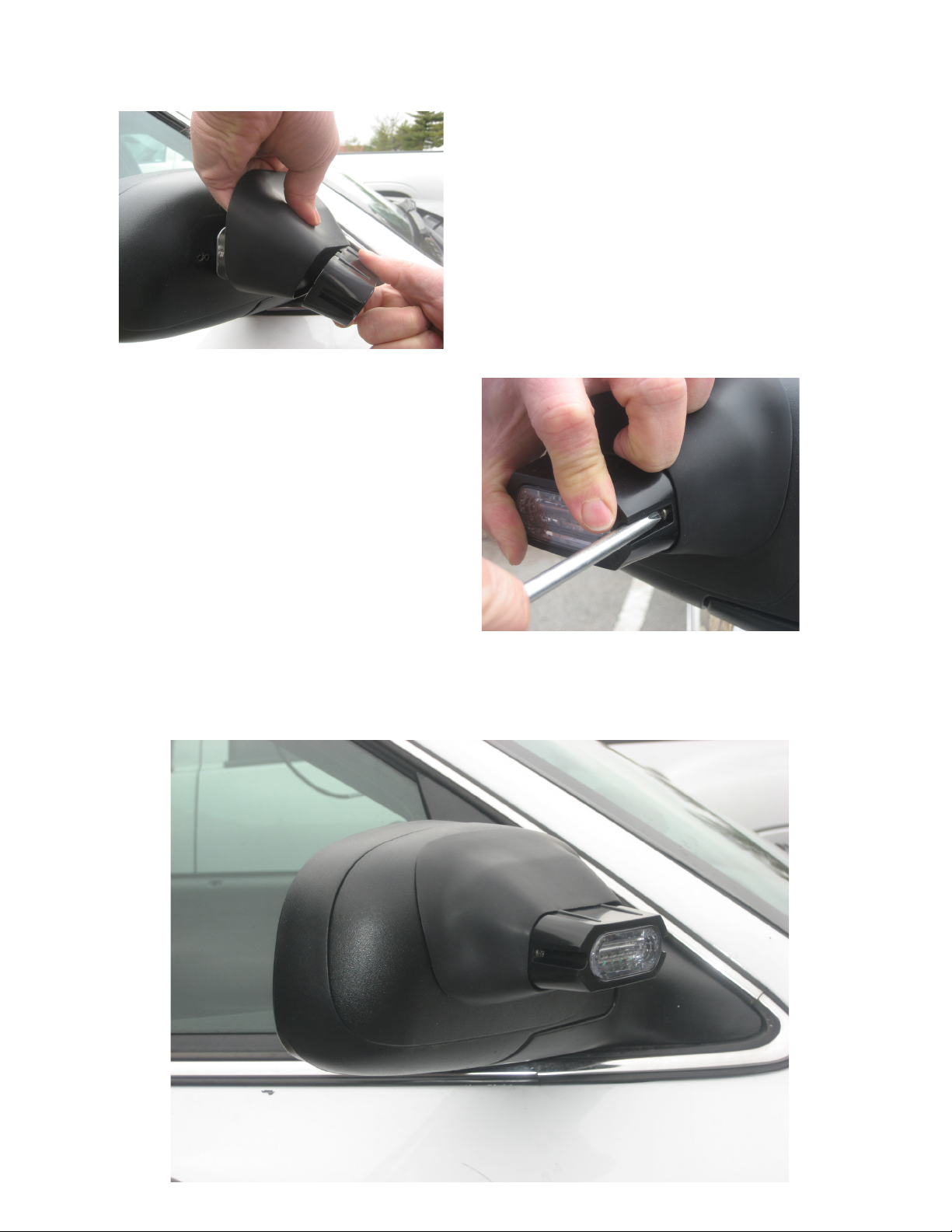
Step 6. Apply front-to-back
pressure to light head and
cover in order to seal cover
to mirror housing and seat
light head against bracket
assembly. Install screws
Step 5. Place light head and
cover over bracket assembly
installed on mirror housing
through front of light head
bezel and into bracket assy.
(Torque light head screws to 6-13 inch lbs)
(DO NOT exceed 13 inch lbs of torque)
(Completed Installation)
(Crown Vic Shown)
5
Page 6

Parts List:
(Kit is sold as a pair)
Component Description: Qty: Part No:
1. All weather cover 2 T56487
2. Bracket (used as mounting and pivot bracket) 4 T56484
3. Star washer 8 T10496
4. Pivot screw 4 T13449
5. Self taping Installation screw 4 T05336
6. Female quick slide connector 6 T04251
7. Male quick slide connector 6 T03383
8. 15 ft cable assembly 2 T09519
9. 11" tie wrap (wiring snake) 2 T00961
10. Mounting bracket for Extended applications 2 T56499
(such as the Ford Expedition)
NOTE:
Light Heads, (purchased separately), contain TRex Exterior LED light, Black bezel
and installation screws used with this kit to perform nal installation of system to
mirror assembly.
Star Washer (x2)
Pivot Screw (x2)
Pemsert on Brackets
Light Head (ordered separately)
Weather Cover
Pivot Bracket
(mounts to light head)
Mounting Bracket
(mounts to mirror) In
applications of a greater
slope than 58 degrees, use
the extended mounting
bracket T56499 included.
6
Page 7

FORD EXPLORER
Installation Examples:
CHEVROLET CAPRICE- (SHOWN ON
FRONT COVER OF MANUAL)
FORD CROWN VIC- (SHOWN ON
PAGE 5 IN MANUAL)
CHEVROLET TAHOE
FORD EXPEDITION
DODGE CHARGER
CHEVROLET IMPALA
(Extended depth mounting bracket used on
vehicles with a greater slope than 32 deg.
off of vertical or 58 degrees horizontal)
(Common pivot bracket is used in all
installations)
Extended mounting
bracket assembly
(Using T56499
Bracket)
7
Page 8
Maintenance:
SANTOPRENE™ and NEOPRENE
Santoprene and Neoprene nishes are very durable and do not require special maintenance. Routine dirt and grime can be removed using a soft, clean cloth or brush and a mild
soap solution. Avoid the use of abrasive cleaners.
WARRANTY
Code 3, ®Inc.'s emergency devices are tested and found to be operational at the time of manufacture. Provided they are installed and
operated in accordance with manufacturer's recommendations, Code 3, Inc. guarantees all parts and components except the lamps to a period
of 1 year (unless otherwise expressed) from the date of purchase or delivery, whichever is later. Units demonstrated to be defective within the
warranty period will be repaired or replaced at the factory service center at no cost.
Use of lamp or other electrical load of a wattage higher than installed or recommended by the factory, or use of inappropriate or inadequate
wiring or circuit protection causes this warranty to become void. Failure or destruction of the product resulting from abuse or unusual use and/or
accidents is not covered by this warranty. Code 3, Inc. shall in no way be liable for other damages including consequential, indirect or special
damages whether loss is due to negligence or breach of warranty.
CODE 3, INC. MAkES NO OTHER ExPRESS OR IMPLIED WARRANTY INCLUDINg, WITHOUT LIMITATION, WARRANTIES Of
fITNESS OR MERCHANTABILITY, WITH RESPECT TO THIS PRODUCT.
PRODUCT RETURNS
If a product must be returned for repair or replacement*, please contact our factory to obtain a Return Goods Authorization Number
(RGA number) before you ship the product to Code 3, Inc. Write the RGA number clearly on the package near the mailing label. Be sure you
use sufcient packing materials to avoid damage to the product being returned while in transit.
*Code 3, Inc. reserves the right to repair or replace at its discretion. Code 3, Inc. assumes no responsibility or liability for expenses incurred for the removal and /or reinstallation of products requiring
service and/or repair.; nor for the packaging, handling, and shipping: nor for the handling of products return to sender after the service has been rendered.
PROBLEMS OR QUESTIONS? CALL OUR TECHNICAL ASSISTANCE HOTLINE (314) 996-2800
WWW.CODE3PSE.COM
Code 3® is a registered trademark of Code 3, Inc., a subsidiary of Public Safety Equipment, Inc.
8
Code 3®, Inc.
St. Louis, Missouri 63114-2029—USA
Ph. (314) 426-2700 Fax (314) 426-1337
10986 N. Warson Road
Part No. T56496 Rev. 0 03/2011
© 2011 Code 3, Inc
 Loading...