

Page 1
INST ALLA TION
& OPERATION
MANUAL
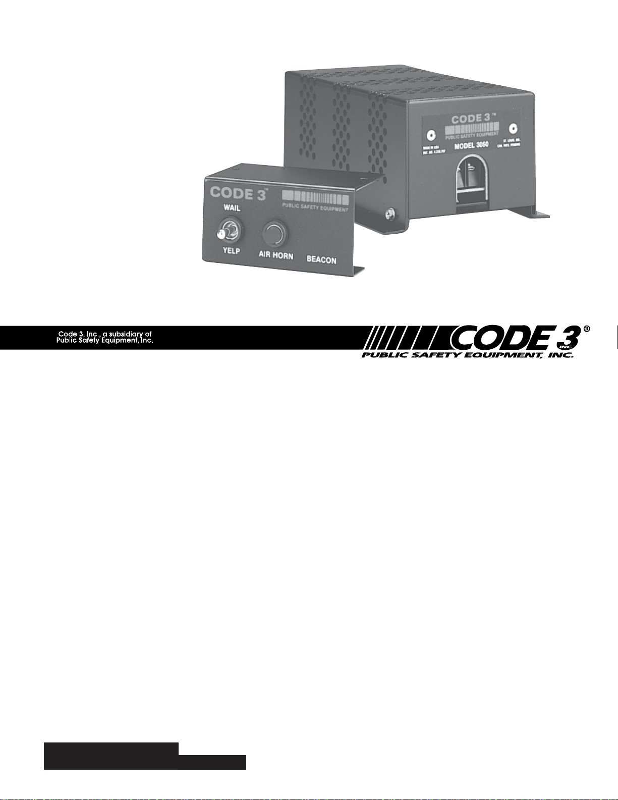
MODEL 3000 & 3050
SIRENS
MODEL 3000 & 3050
UNDERCOVER SIRENS
Contents:
Introduction........................................................... 2
Unpacking & Pre-Installation ............................... 2
Installation & Mounting ........................................ 2
Wiring .............................................................. 3
Speaker Connections...................................... 4
Terminal Block Connections ........................... 4
Set-Up and Adjustment........................................ 4
Operation.............................................................. 5
Wiring Diagram .................................................... 5
Maintenance ........................................................ 6
Troubleshooting ................................................... 6
Parts List (Replacement Parts / Exploded View)7-8
Specifications....................................................... 9
Notes .................................................................... 9
Warranty .............................................................10
IMPORTANT:
Read all instructions and warnings before installing and using.
INSTALLER: This manual must be delivered to the end user of this equipment.
Page 2
Introduction
!
The Code 3® Model 3000 Electronic Siren produces two distinct tones, "Wail" and "Yelp". Model 3050
produces three distinct tones, "Wail", "Yelp" and "Air Horn".
Sirens are an integral part of an effective audio/visual emergency warning system. However, sirens are only short range secondary warning devices. The use of a siren does not
insure that all drivers can or will observe or react to an emergency warning signal, particu-
WARNING!
SIREN PRODUCTS:
larly at long distances or when either vehicle is traveling at a high rate of speed. Sirens
should only be used in a combination with effective warning lights and never relied upon as
a sole warning signal. Never take the right of way for granted. It is your responsibility to
be sure you can proceed safely before entering an intersection, driving against traffic, or
responding at a high rate of speed.
The effectiveness of this warning device is highly dependent upon correct mounting and
wiring. Read and follow the manufacturer’s instructions before installing or using this
device. The vehicle operator should check the equipment daily to insure that all features of
the device operate correctly.
To be effective, sirens must produce high sound levels that potentially can inflict hearing
damage. Installers should be warned to wear hearing protection, clear bystanders from the
area and not to operate the siren indoors during testing. Vehicle operators and occupants
should assess their exposure to siren noise and determine what steps, such as consultation with professionals or use of hearing protection should be implemented to protect their
hearing.
This equipment is intended for use by authorized personnel only. It is the user’s responsibility to understand and obey all laws regarding emergency warning devices. The user
should check all applicable city, state and federal laws and regulations.
Public Safety Equipment, Inc., assumes no liability for any loss resulting from the use of
this warning device.
Proper installation is vital to the performance of the siren and the safe operation of the
emergency vehicle. It is important to recognize that the operator of the emergency vehicle
is under psychological and physiological stress caused by the emergency situation. The
siren system should be installed in such a manner as to: A) Not reduce the acoustical
performance of the system, B) Limit as much as practical the noise level in the passenger
compartment of the vehicle, C) Place the controls within convenient reach of the operator
so that he can operate the system without losing eye contact with the roadway.
Emergency warning devices often require high electrical voltages and/or currents. Properly protect and use caution around live electrical connections. Grounding or shorting of
electrical connections can cause high current arcing, which can cause personal injury and/
or severe vehicle damage, including fire.
PROPER INSTALLATION COMBINED WITH OPERATOR TRAINING IN THE PROPER
USE OF EMERGENCY WARNING DEVICES IS ESSENTIAL TO INSURE THE SAFETY
OF EMERGENCY PERSONNEL AND THE PUBLIC.
Unpacking & Pre-installation
After unpacking your 3000 or 3050 series siren, carefully inspect the unit and
associated parts for any damage that may have been caused in transit.
Report any damage to the carrier immediately. Before discarding the
packaging material, check to see that you have the following:
1. Siren and Cover
2. User Parts Bag (#S91017 - Model 3000 or #S91018 Model 3050)
Installation & Mounting
Mounting
The 3000 and 3050 series sirens can be mounted anywhere in the passenger compartment that will
provide adequate ventilation. It is not recommended that the unit be placed in the direct path of heater
duct discharge. Do not mount in the engine compartment or any other area subject to high heat or
moisture.
2
Fig. 1
Page 3
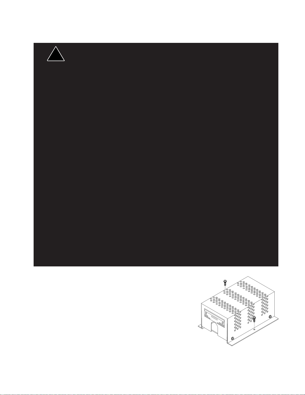
Mount the siren with the (2) supplied #8 screws into a secured portion of
!
!
sheet metal. See Fig. 1.
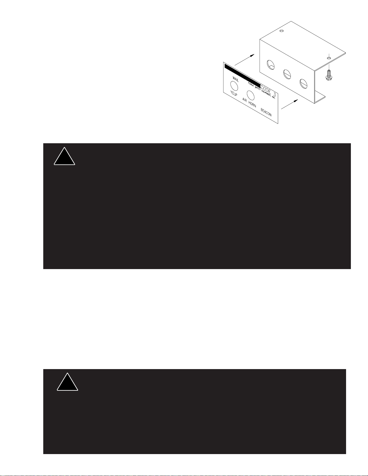
Remove the backing from the adhesive faceplate and place the
faceplate over the three hole bracket, see Fig. 2. Should you wish
to install a switch for a beacon, carefully cut the faceplate with a
sharp knife from the front to expose the extra hole in the bracket
and then mount the bracket with the remaining (2) #8 screws. The
bracket should be mounted in a location that will provide
convenience for the operator.
For custom installations, such as in a console or in-dash mounting, the
three hole bracket may be used as a drilling template and the faceplate then
applied directly to the dash or console surface.
All devices should be mounted in accordance with the manufacturer's instructions and
securely fastened to vehicle elements of sufficient strength to withstand the forces applied to
the device.
WARNING!
Ease of operation and convenience to the operator should be the prime consideration when
mounting the siren and controls. Adjust the mounting angle to allow maximum operator
visibility.
Do not mount the Control Head Module in a location that will obstruct the drivers view.
Devices should be mounted only in locations that conform to their SAE identification code as
described in SAE Standard J1849. For example, electronics designed for interior mounting
should not be placed underhood, etc.
Controls should be placed within convenient reach* of the driver or if intended for two person
operation the driver and/or passenger. In some vehicles, multiple control switches and/or
using methods such as "horn ring transfer" which utilizes the vehicle horn switch to toggle
between siren tones may be necessary for convenient operation from two positions.
*
Convenient reach is defined as the ability of the operator of the siren systems to manipulate
the controls from his normal driving/riding position without excessive movement away from
the seat back or loss of eye contact with the roadway.
Fig. 2
Wiring
Wire should be #16 gauge, or larger for all connections to the switch, push-button (3050), and the
siren unit. Speaker wire should be #18 gauge or larger. For protection of the wiring and the siren
unit, the in-line fuse and fuseholder supplied should be located as close to the battery as practical.
For proper operation, ground the siren unit negative (earth) terminal to the vehicle frame as close to
the unit as possible. Be sure to scrape away the paint down to the bare metal.
For maximum reliability, it is recommended that all connections be soldered with 60/40 resin core
solder. Should you prefer to crimp the terminals to the wires, be sure that all crimp connections are
tight and that the wire cannot be pulled loose from the terminal. It is further recommended that
wirenut connections be soldered first.
Route all wiring in such a manner as to prevent abrasion between the wires and the metal vehicle
surfaces. Cut off and discard any excess wire.
WARNING!
Larger wires and tight connections will provide longer service life for components. For high
current wires it is highly recommended that terminal blocks or soldered connections be used
with shrink tubing to protect the connections. Do not use insulation displacement
connectors (e.g. 3M® Scotchlock type connectors). Route wiring using grommets and
sealant when passing through compartment walls. Minimize the number of splices to
reduce voltage drop. High ambient temperatures (e.g. underhood) will significantly reduce
the current carrying capacity of wires, fuses, and circuit breakers. Use "SXL" type wire in
engine compartment. All wiring should conform to the minimum wire size and other
recommendations of the manufacturer and be protected from moving parts and hot
surfaces. Looms, grommets, cable ties, and similar installation hardware should be used to
anchor and protect all wiring.
3
Page 4

!
!
Fuses or circuit breakers should be located as close to the power takeoff points as possible
!
and properly sized to protect the wiring and devices.
Particular attention should be paid to the location and method of making electrical
WARNING!
CONTINUED
connections and splices to protect these points from corrosion and loss of conductivity.
Ground terminations should only be made to substantial chassis components, preferably
directly to the vehicle battery.
The user should install a fuse sized to approximately 125% of the maximum Amp capacity
in the supply line to protect against short circuits. For example, a 30 Amp fuse should
carry a maximum of 24 Amps. DO NOT USE 1/4" DIAMETER GLASS FUSES AS THEY
ARE NOT SUITABLE FOR CONTINUOUS DUTY IN SIZES ABOVE 15 AMPS. Circuit
breakers are very sensitive to high temperatures and will "false trip" when mounted in hot
environments or operated close to their capacity.
Speaker Connections
Determine the power rating of your speaker(s) at this point.
Speaker Phasing - Whenever two speakers are used from one amplifier (two 58 watt, two 100 watt,
or two 100 watt in the PSE200 configuration), they must be phased for maximum performance.
Phasing involves connecting both speaker terminals marked #1 on the speaker together and
connecting both speaker terminals marked #2 on the speaker together. Be sure to check the
speaker terminals for the numbers, as the wire colors or speaker installation may be arbitrary.
CONNECTION OF A 58 WATT SPEAKER TO THE 100 WATT TERMINAL WILL CAUSE
THE SPEAKER TO BURN OUT, AND WILL VOID THE SPEAKER WARRANTY!
The sound projection opening should be pointed forward, parallel to the ground, and not
WARNING!
obstructed or muffled by structural components of the vehicle. Concealed or under-hood
mounting in some cases will result in a dramatic reduction in performance. To minimize this
reduction, mount the speaker so the sound emitted is projected directly forward and
obstruction by vehicle components such as hoses, brackets, grille, etc. is minimized.
Electromechanical sirens and electronic siren speakers should be mounted as far from the
occupants as possible using acoustically insulated compartments and isolation mounting to
minimize the transmission of sound into the vehicle. It may be helpful to mount the device on
the front bumper, engine cowl or fender; heavily insulate the passenger compartment; and
operate the siren only with the windows closed.
Each of these approaches may cause significant operational problems, including loss of siren
performance from road slush, increased likelihood of damage to the siren in minor collisions,
and the inability to hear the sirens on other emergency vehicles. APPROPRIATE TRAINING
OF VEHICLE OPERATORS IS RECOMMENDED TO ALERT THEM TO THESE
PROBLEMS AND MINIMIZE THE EFFECT OF THESE PROBLEMS DURING
OPERATIONS.
Terminal Block Connections
(-) - Negative (ground/earth) source of supply.
(+) - Application of +12 VDC to this terminal will cause the siren to activate and produce the "Wail"
tone.
A - (3050 Only) Application of +12 VDC to this terminal will produce "Air Horn" tone. Power need
not be supplied to (+) to terminal B.
B - Application of +12 VDC to this terminal while the siren is energized [+12 VDC on terminal (+)]
will produce the Yelp tone.
Common - Speaker common terminal.
58 - 58 watt speaker(s) terminal.
100 - 100 watt speaker(s) terminal. Note: Connection of a 58 watt speaker to this terminal and the
common terminal may destroy the speaker.
SET-UP AND ADJUSTMENT
Any electronic device may create or be affected by electromagnetic interference. After
installation of any electronic device, operate all equipment simultaneously to insure that
WARNING!
operation is free of interference. The speaker to Common and 58 (58 watt) or common
4
Page 5

Wire the speaker to Common and 58 (58 watt) or Common and 100 (100 watt) using the #18 "Zip
!
Cord" supplied. Connect the "Zip Cord" to the speaker wires with (2) wirenuts. Determine which
speaker you have prior to connection. Connection of a 58 watt speaker to the 100 watt terminal will
destroy the speaker. Ground [earth or (-) terminal] the unit to the vehicle frame using the #16 gauge
black wire and #8 ring terminal. Install #16 fork terminals on the red, white and yellow wires (one end
only). For Model 3050, also install a terminal on the green wire in a similar manner. Install the red,
yellow and white wires on the center off switch as shown in Fig 3. On Model 3050, also install the red
jumper wire (between the switch and the push-button), and install the green wire on the push-button.
After making sure that all connections are tight, install the switch (and push-button for Model 3050) in
the mounting bracket. If mounting the Beacon switch in the siren switch bracket, install and wire it at
this time. Do Not Wire the Beacon and Siren on the Same Power Feed Line. Use separate
supply wires and fuses. Connect the white wire to the terminal marked (+) in the siren. Connect the
yellow wire to terminal B at the siren. For Model 3050, connect the green wire to terminal A at the
siren. Replace the siren cover. Be certain the wires are not caught between the cover and chassis.
Replace the four cover screws. Place the center off toggle switch in the center position. Using a
wirenut, connect one end of the in-line fuseholder to the red wire coming from the center off switch,
as close to the power take off point as possible. Connect the other end of the in-line fuseholder to
either the battery positive terminal or to the starter solenoid positive post. A 3/8" ring terminal is
supplied (if needed) for this purpose. Insert the 14 amp fuse in the in-line fuseholder.
Fig. 3
OPERATION
"Wail" and "Yelp" tones are in some cases (such as in the state of California) the only
recognized siren tones for calling for the right of way. Ancillary tones such as "Air Horn" in
some cases do not provide as high a sound pressure level. It is recommended that these
tones be used in a secondary mode to alert motorists to the presence of multiple emergency
WARNING!
Model 3000 - This siren is controlled by a center off, remotely mounted switch. Up is the wail option and
down is the Yelp option.
Model 3050 - Same as Model 3000, it also has a push-button for the Airhorn option.
Testing the Siren
vehicles or to momentarily shift from the primary tone as an indication of the imminent
presence of an emergency vehicle.
For Model 3050, with the switch in the Off position, depress the Air Horn button. The Air Horn
should be heard.
5
Page 6

Place the switch in the wail or Yelp position and depress the Air Horn button. The Air Horn
should override the wail and Yelp tones.
MAINTENANCE
Your Code 3® 3000/3050 SERIES siren has been designed to provide trouble free service. In case of
difficulty, see the troubleshooting guide below. Also check for shorted or open wires. The primary cause of
short circuits has been found to be wires passing through firewalls, roofs, etc. The following periodic
maintenance is, recommended:
A. Check all terminals and connections to insure that they are tight.
B. Remove the siren cover and blow out any accumulated dust or dirt.
C. Inspect the speaker to insure that it is not clogged with dirt, leaves, etc.
A schematic wiring diagram and technical description are available from the factory upon request.
TROUBLESHOOTING
(Refer to wiring diagram page 5)
PROBLEM
NO OUTPUT
EXTERNAL 14A
FUSE BLOWS.
NO OUTPUT FROM
SPEAKER, TONES
HEARD INSIDE
AMP. MODULE.
SIREN TONES
VOLUME TOO
LOW/GARBLED.
PROBABLE CAUSE
A. SIREN NOT CONNECTED TO
POWER SOURCE
B. EXTERNAL 14A FUSE MISSING/
OPEN
C. VEHICLE SUPPLY FUSE OPEN
A. SPEAKER(S) SHORTED
A. SPEAKER NOT CONNECTED/
OPEN CIRCUIT IN SPEAKER WIRING
B. SPEAKER(S) OPENED
A. LOW VOLTAGE TO SIREN
AMPLIFIER
B. DEFECTIVE SPEAKER/ HIGH
RESISTANCE IN WIRING
C. SPEAKERS PHASED IMPROPERLY
REMEDY
A. CHECK
CONNECTIONS
B. REPLACE FUSE
C. REPLACE FUSE
A. REPLACE
SPEAKER(S)
A. CHECK SPEAKER
WIRING
B. REPLACE
SPEAKER(S)
A. CHECK WIRING FOR
BAD CONNECTIONS/
CHECK VEHICLE
CHARGING SYSTEM
B. CHECK SPEAKER(S)
WIRING/REPLACE
SPEAKER(S)
C. REFER TO PAGE 4
FOR PROPER PHASING
SIREN RUNS PROPERLY
BUT SHUTS DOWN
WHILE RUNNING, THEN
STARTS RUNNING
AGAIN AFTER A FEW
MINUTES
A. VEHICLE CIRCUIT BREAKERS
NOT RATED PROPERLY, AND ARE
OVERHEATING
6
A. REFER TO
SPECIFICATIONS
SECTION, PAGE 9. USE
A BREAKER WITH AT
LEAST TWICE THE
AMPERAGE RATING
FOR THE WATTAGE
BEING USED. (I.E. 200
WATT = 30 A MIN.)
Page 7

Parts List
Ref No. Description Part No. Qty.
1 Siren Cover - Model 3000 S91010M 1
- Model 3050 S91011M
2 #8 x 3/8 Sheet Metal Screw T00243 4
3 Circuit Board - Model 3000 T50054 1
- Model 3050 T50055
4 #4-40 Nut T00393 6
5 #8-32 Nut T00674 2
6 #8 Spacer T00762 2
7 #4-40 Hex Spacer T00760 4
8 #4-40 Ext. Tooth Screw T01086 2
9 #4 Lockwasher T00677 2
10 Rivet Burr (Washer) T00095 6
11 Power Transistor Insulator Pad T00618 2
12 Electrical Transistor Paper Insulator T01067 2
13 Transistor T07639 2
14 #4-40 Machine Screw T00679 4
15 #8-32 Machine Screw T00763 2
16 Transistor Cover T00952 2
Parts Not Shown
Siren ID Serial Number T00765 1
Teflon Sleeve T01233 4
Parts Bag - Model 3000 T04672 1
- Model 3050 T04673 1
Switch, DPDT, Center Off W/Jumper (3000 and 3050) T00766 1
Switch, SPST, White Push Button (3050 Only) T00773 1
7
Page 8

Fig. 4
8
Page 9

Specifications
Input Voltage - 10 to 16 VDC, negative ground (earth).
(Note: Operation above 15 VDC for an extended period of time may result in speaker damage.)
Operating Current: One 58 watt speaker - 5.5 Amps
Two 58 watt speakers - 9 Amps
One 100 watt speaker - 9 Amps
Two 100 watt speakers - 15 Amps
Cycle Rate: WAIL - 11 cycles/minute.
YELP - 200 cycles/minute.
Frequency: WAIL - 650 to 1800 Hz.
YELP - 650 to 1800 Hz.
Notes:
9
Page 10

WARRANTY
This product was tested and found to be operational at the time of manufacture. Provided this product is
installed and operated in accordance with the manufacturer's recommendations, Code 3, Inc. guarantees all parts
and components except the lamps for a period of 1 year from the date of purchase or delivery, whichever is later.
Units demonstrated to be defective within the warranty period will be repaired or replaced at the factory service
center at no cost.
Use of a lamp or other electrical load of a wattage higher than installed or recommended by the factory, or
use of inappropriate or inadequate wiring or circuit protection causes this warranty to become void. Failure or
destruction of the product resulting from abuse or unusual use and/or accidents is not covered by this warranty.
Code 3, Inc. shall in no way be liable for other damages including consequential, indirect or special damages
whether loss is due to negligence or breach of warranty.
CODE 3, INC. MAKES NO OTHER EXPRESS OR IMPLIED WARRANTY INCLUDING, WITHOUT
LIMITATION, WARRANTIES OF FITNESS OR MERCHANTABILITY, WITH RESPECT TO THIS PRODUCT.
PRODUCT RETURNS
In order to provide you with significantly faster service, if you are going to return a product for repair or
replacement*, please contact our factory to obtain a Return Goods Authorization Number (RGA number) before you
mail the product to Code 3, Inc. Write the RGA number clearly on the package near the mailing label. Be sure you
use sufficient packing materials to avoid damage to the product being returned while in transit. All plastic domes and
optical lenses are NOT returnable for credit or exchange.
*Code 3, Inc. reserves the right to repair or replace product at its discretion. PSE assumes no responsibility or liability for expenses incurred for the removal and/or
reinstallation of products requiring service and/or repair.
PROBLEMS OR QUESTIONS? CALL OUR TECHNICAL ASSISTANCE HOTLINE (314) 996-2800
St. Louis, Missouri 63114-2029—USA
Ph. (314) 426-2700 Fax (314) 426-1337
10986 N. Warson Road
Code 3, Inc.
www.code3pse.com
Code 3 is a registered trademark of Code 3, Inc. a subsidiary of Public Safety Equipment, Inc.
3M is a registered trademark of 3M Company, Inc.
Revision 9, 11/05- Instruction Book Part No. T00820
©2005 Public Safety Equipment, Inc. Printed in USA
 Loading...