

Page 1
INSTALLATION
& OPERATION
MANUAL
HB6PAKX & HB6PAKXX
HIDE-A-BLAST
HB6PAK-PI-X
NGPI TWIST LOCK
HIDE-A-BLAST
LED WARNING LIGHT
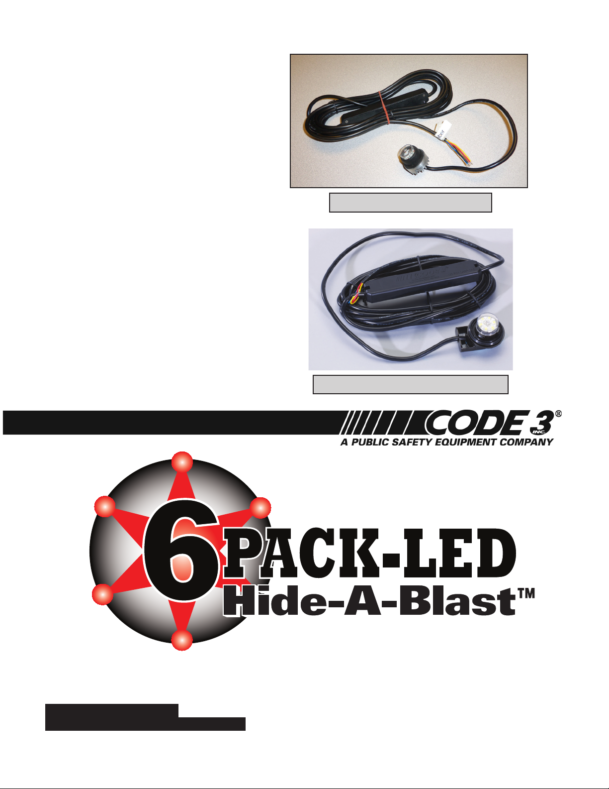
STANDARD HIDE A BLAST UNIT
NGPI TWIST LOCK HIDE A BLAST UNIT
6 LED
IMPORTANT:
WARNING LIGHT
Read all instructions and warnings before installing and using.
INSTALLER: This manual must be delivered to the end user of this equipment.
Page 2

Introduction
The HB Series LED light represents the latest in state-of-the-art LED warning technology. The latest in
MOSFET technology and advanced design provide efcient operation, superior performance, reliability
and long life. The use of microprocessor control allows the HB Series to offer more light pattern options
and versatility than any other remote system available. The user may select Single, Double, Triple, Quad,
Variable Flash, Double-Double or Triple Flash Patterns.
Standard Features
The HB Series HIDE-A-BLAST LED light is available in a single unit package complete with
installation instructions. Multiple HB Series LED Lights can be connected together and operated
from the same control switch. All HB Series LED Lights have the following features:
12 OR 24 VDC OPERATION
REVERSE POLARITY PROTECTED
MULTIPLE USER SELECTABLE FLASH PATTERNS
See Flash Pattern Selection, page 6.
Note: A user supplied fuse must be installed in series with the red wire. Install the fuse near the
power source. The fuse should be sized to the nearest standard size fuse that is approximately
125% of the combined total current of all HB Series LED Lights installed on the circuit. As
an example, two HB Series LED Lights should be fused at 3A for 12VDC operation, 1A for 24V
operation.
Specications
MODEL VARIANTS:
HB6PAKX & HB6PAKXX = 6 LEDs
X denotes the LED color, Red, Blue, Amber or White (R, B, A or W) and dual color
combinations of Amber/White, Red/Blue, Red/White or Blue/White (AW, BR, RW or BW).
i.e. HB6PAKW has six white LEDs.
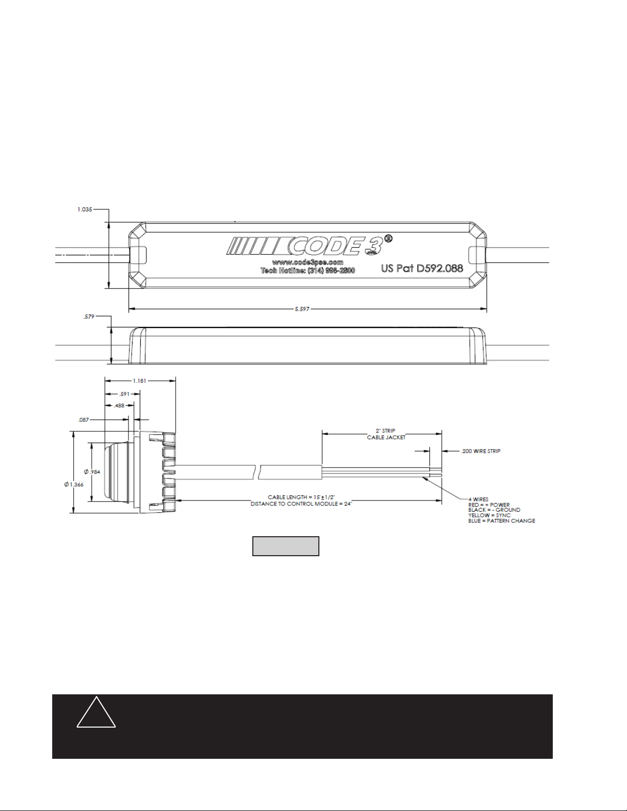
MECHANICAL SPECIFICATIONS:
CABLE LENGTH: 15 feet
DIMENSIONS: See gure A
BOXED WEIGHT: 0.9lb
UNBOXED WEIGHT: 0.8lb
LED COLOR: Red, Blue, Amber or White (mixing of colors in the same unit is not supported)
LENS COLOR: clear
ELECTRICAL SPECIFICATIONS:
OPERATING VOLTAGE & POLARITY: 11-30VDC, Neg or Pos ground
AVERAGE CURRENT: 0.6A @ 13.8VDC
OPERATING TEMPERATURE: -30 to 150 F
INPUT POWER: 8W
OPERATING MODES: Synchronous and Non-Synchronous
Page 3

WARNING!
The use of this or any warning device does not ensure that all drivers can or will observe or react to an
emergency warning signal. Never take the right-of-way for granted. It is your responsibility to be sure you can
proceed safely before entering an intersection, driving against trafc, responding at a high rate of speed, or
walking on or around trafc lanes. The effectiveness of this warning device is highly dependent upon correct
mounting and wiring. Read and follow the manufacturer’s instructions before installing or using this device. The
vehicle operator should insure daily that all features of the device operate correctly. In use, the vehicle operator
should insure the projection of the warning signal is not blocked by vehicle components (i.e.: open trunks or
compartment doors), people, vehicles, or other obstructions. This equipment is intended for use by authorized
personnel only. It is the user’s responsibility to understand and obey all laws regarding emergency warning
devices. The user should check all applicable city, state and federal laws and regulations. Code 3, Inc., assumes
no liability for any loss resulting from the use of this warning device. Proper installation is vital to the performance
of this warning device and the safe operation of the emergency vehicle. It is important to recognize that the
operator of the emergency vehicle is under psychological and physiological stress caused by the emergency
situation. The warning device should be installed in such a manner as to: A) Not reduce the output performance
of the system, B) Place the controls within convenient reach of the operator so that he can operate the system
without losing eye contact with the roadway. Emergency warning devices often require high electrical voltages
and/or currents. Properly protect and use caution around live electrical connections. Grounding or shorting of
electrical connections can cause high current arcing, which can cause personal injury and/or severe vehicle
damage, including re. Any electronic device may create or be affected by electromagnetic interference. After
installation of any electronic device operate all equipment simultaneously to insure that operation is free of
interference. Never power emergency warning equipment from the same circuit or share the same grounding
circuit with radio communication equipment. All devices should be mounted in accordance with the manufacturer's
instructions and securely fastened to vehicle elements of sufcient strength to withstand the forces applied to the
device. Driver and/or passenger air bags (SRS) will affect the way equipment should be mounted. This device
should be mounted by permanent installation and within the zones specied by the vehicle manufacturer, if any.
Any device mounted in the deployment area of an air bag will damage or reduce the effectiveness of the air
bag and may damage or dislodge the device. Installer must be sure that this device, its mounting hardware and
electrical supply wiring does not interfere with the air bag or the SRS wiring or sensors. Mounting the unit inside
the vehicle by a method other than permanent installation is not recommended as unit may become dislodged
during swerving, sudden braking or collision. Failure to follow instructions can result in personal injury. PROPER
INSTALLATION COMBINED WITH OPERATOR TRAINING IN THE PROPER USE OF EMERGENCY WARNING
DEVICES IS ESSENTIAL TO INSURE THE SAFETY OF EMERGENCY PERSONNEL AND THE PUBLIC.
Unpacking and Pre-installation
Remove the product from the box and examine the unit for any shipping damage. Report any damage to the
carrier immediately. Inspect the contents to be certain that the following items are included:
A. 1 HB6PAK Series LED Light with 15 ft. Cable
B. 1 Installation Manual
3
Page 4
Installation and Mounting
1. First, carefully plan the installation so that the HB Series LED Lights will not interfere with the mounting or
operation of the vehicle's existing light xtures. Using a 1 inch hole saw, cut a hole in the vehicle's light xture
in a location that will allow the HB Series LED light to be mounted in such a way that it will provide maximum
light inside the reector (see Figure B). Use a deburring tool to remove burrs and to chamfer the edge of the
hole before inserting the HB6PAK. Proper installation will provide an excellent seal and prevent water from
entering the light xture.
FIGURE A
Wiring
1. Install the LED light heads in the desired locations.
2. Route the cables between the light heads and the control switch panel. Make sure the cable is secure along
the chosen routing inside the vehicle to prevent damage by chang or binding. Be sure to keep the cables away
from engine hot spots.
3. Secure the cables and the HB Series asher module using plastic wire ties.
!
WARNING!
The HB Series LED Light components are water resistant but NOT waterproof and should
be located in an area protected from the weather and water.
4
Page 5

4. For synchronized operation of multiple HB Series lights
the yellow wires from each unit's cable must be connected
together. Insulate this connection using an insulated butt splice
to prevent accidental contact with power or ground.
Connections:
Red +Power (11-30VDC)
Black Ground
Yellow Synchronization
Blue Pattern Selection
The HB6PAK light should be fully inserted into the hole so
that the aluminum heatsink is against the light housing and
the grove of the rubber seal is locked into the hole. This will
provide a secure installation and a highly water resistant
seal.
FIGURE B
IMPORTANT: To extend the power (+) and ground (-) wires, use the following as a guide.
1 to 10 ft. use 20AWG wire
10 to 50 ft. use 18AWG wire
Pattern Selection Timing
Time Function
0~1 sec NEXT PATTERN / ON
1~3 sec PREVIOUS PATTERN
3~5 sec P19 CYCLE FLASH
>5 sec OFF
5
Page 6

FLASH PATTERN SELECTION
FLASH MODE
Any one of the 20 Flash Patterns may be selected by using the blue wire to scroll through the patterns. Touch the blue wire to ground for about 1 second and then remove it. The ash pattern will
switch to the next pattern. When the yellow wires (SYNC) from each light are connected, lights
with Phase 1 patterns selected will ash in an alternating sequence with lights that have a Phase 2
pattern selected. The following patterns are available.
Description
1. signal alert alternating (Factory Default)
2. signal alert simultaneous phase1
3. signal alert simultaneous phase2
4. rapid ash alternating
5. rapid ash simultaneous phase1
6. rapid ash simultaneous phase2
7. single ash 75 alternating
8. single ash 75 simultaneous phase1
9. single ash 75 simultaneous phase2
10. single ash 375 alternating
11. single ash 375 simultaneous phase1
12. single ash 375 simultaneous phase2
13. action ash alternating
14. action ash simultaneous
15. modul ash alternating
16. modul ash simultaneous
17. action scan
18. STEADY
19. Cycle Flash
20. off
1. Connect the Power/Control wire harness assembly to a switch. To select one of the 30 different ash functions, turn the light on and touch the bare end of the blue wire to ground for about one second. You can also
scroll backward through the ash pattern table (see the PATTERN SELECTION TIMING section for complete
details. Repeat this process until you reach the desired ash pattern. After you have selected the desired
ash pattern, you should cover the bare end of the blue wire with heat shrinkable tubing to prevent an ac-
6
Page 7

cidental pattern change or short circuit. The ash pattern may also be selected remotely by the operator by
connecting the blue wire to the ground through a Normally Open (NO) Momentary Push Button Switch. For
synchronized simultaneous ashing, set all HB Series LED lights to a Phase 1 ash pattern. For synchronized - alternating ashing, set a Phase 1 pattern on one HB Series LED light and a Phase 2 pattern on
the other unit. The factory default ash pattern may be restored by holding the blue wire to ground for 3~5
seconds.
MAINTENANCE
The HB Series LED light has been designed to provide trouble free service. In case of difculty, refer to the
Troubleshooting section. Periodic inspection of product's wiring connections for shorted or open wires will
assure trouble free operation. The primary cause of short circuits has been found to be wires passing through
rewalls, roofs, etc.
Troubleshooting
NOTE: DO NOT TAMPER WITH THE LED OR FLASHER MODULES. THIS PRODUCT IS SOLD
AS A COMPLETE SYSTEM, AND IS NOT DESIGNED FOR FIELD REPAIR. ANY ATTEMPT TO
DISASSEMBLE THE PRODUCT WILL VOID THE WARRANTY.
All HB Series LED lights are thoroughly tested before shipment. However, should you encounter a
problem during installation or during the life of the product, refer to the guide below for information on
troubleshooting. In most cases problems that occur will be related either to the power/control wiring.
PROBLEM
External fuse blows
Light heads do not ash
Incorrect ash pattern
TROUBLESHOOTING GUIDE
1. Power input wires shorted
2. Incorrect fuse size
3. Flasher Module Failed
1. Wire connections loose at
switch panel or power source
2. Cable to light heads dam-
aged and shorting to chassis
3. Flash Pattern is set to OFF
1. Wrong Flash Pattern is
selected.
1. Check power connections
2. Replace with correct size fuse
3. Return for Service
1. Check all connections
2. Isolate damaged cable by disconnecting
and reconnecting outputs one at a time.
Repair the damaged cable.
3. Select valid ashing pattern
1. See FLASH PATTERN SELECTION.
SOLUTION
Flash patterns change
continuously
1. Unit is in CYCLE FLASH
mode. Proper operation.
1. This is normal operation for this mode. If
CYCLE FLASH MODE is not desired see
FLASH PATTERN SELECTION.
7
Page 8

Installation & Mounting-NGPI Twist Lock Version
Step-1. Locate the NGPI light bulb plug (see Figure 1).
Step-2. Remove the NGPI light bulb plug by rotating it counter clockwise until the bulb plug relsases (see
Figure 2).
Step-3. Take note of the positions of the retention cam clearance notches and Insert the Twist Lock Hide A
Blast unit so that the retention cams t through the holes in the NGPIs headlight assembly (see Figure 3 and
then 4).
Step-4. Rotate the Twist Lock Hide A Blast Unit clockwise as far as it goes to lock it into place in the NGPI
headlight housing (see Figure 5 page 9)
FIGURE 1
FIGURE 3
FIGURE 2
FIGURE 4
8
Page 9

FIGURE 5
9
Page 10

NOTES:11NOTES:
10
Page 11

Page 12

WARRANTY
This product was tested and found to be operational at the time of manufacture. Provided this
product is installed and operated in accordance with the manufacturer's recommendations, Public
Safety Equipment guarantees the HB Series LED Light for a period of 5 years from the date of purchase or delivery, whichever is later. Units demonstrated to be defective within the warranty period will
be repaired or replaced at the factory service center at no cost.
Improper installation or use of inappropriate or inadequate wiring or circuit protection causes
this warranty to become void. Failure or destruction of the product resulting from abuse or unusual
use and/or accidents is not covered by this warranty. Use of non-PSE components and assemblies
may cause damage to the system and/or personal injury, and voids all warranties on PSE systems
and components.
PSE shall in no way be liable for other damages including consequential, indirect or special
damages whether loss is due to negligence or breach of warranty.
PSE MAKES NO OTHER EXPRESS OR IMPLIED WARRANTY INCLUDING, WITHOUT
LIMITATION, WARRANTIES OF FITNESS OR MERCHANTABILITY, WITH RESPECT TO THIS
PRODUCT.
PRODUCT RETURNS
In order to provide you with faster service, if you are going to return a product for repair or
replacement*, please contact our factory to obtain a Return Goods Authorization Number (RGA
number) before you ship the product to PSE. Write the RGA number clearly on the package near
the mailing label. Be sure you use sufcient packing materials to avoid damage to the product being
returned while in transit.
*PSE reserves the right to repair or replace product at its discretion. PSE assumes no responsibility or liability for expenses incurred for the removal and/or reinstallation of products requiring service and/or repair.
For Technical Support / Service, please call 314-996-2800
Public Safety Equipment, Inc.
10986 N. Warson Road
St. Louis, Missouri 63114-2029—USA
Ph. (314) 426-2700 Fax (314) 426-1337
Code 3 is a registered trademark of Public Safety Equipment, Inc. a subsidiary of Public Safety Equipment, Inc.
CycleFlash is a trademark of Public Safety Equipment, Inc.
Revision 1, 10/12- Instruction Book Part No. T11788
©2012 Public Safety Equipment, Inc. Printed in USA
 Loading...