

Page 1
INSTALLATION
& OPERATION
MANUAL
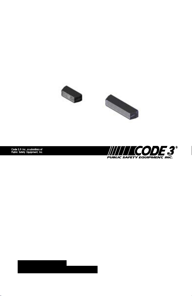
EXTERIOR CODE 3® TORUSTM
MODULES
3-LED
6-LED
TORUS
Contents:
IMPORTANT:
TM
EXTERNAL
MODULES
Introduction........................................................ 3
Features and Specications................................ 3
Installation......................................................... 4
Wiring............................................................... 5
Programming................................................... 5-6
Maintenance.......................................................7
Warranty........................................................... 8
Read all instructions and warnings before installing and using.
INSTALLER: This manual must be delivered to the end
user of this equipment.
Page 2

This Product contains high intensity LED
devices. To prevent eye damage, DO NOT
stare into light beam at close range.
The use of this or any warning device does not insure that all drivers can or will observe or react to an emergency warning signal.
Never take the right-of-way for granted. It is your responsibility
to be sure you can proceed safely before entering an intersec-
tion, driving against trafc, responding at a high rate of speed,
or walking on or around trafc lanes.
The effectiveness of this warning device is highly dependent upon
correct mounting and wiring. Read and follow the manufacturer’s
instructions before installing or using this device. The vehicle
operator should insure daily that all features of the device operate
correctly. In use, the vehicle operator should insure the projection
of the warning signal is not blocked by vehicle components (i.e.:
open trunks or compartment doors), people, vehicles, or other
obstructions. This equipment is intended for use by authorized
personnel only. It is the user ’s responsibility to understand and obey
all laws regarding emergency warning devices. The user should
check all applicable city, state and federal laws and regulations.
Code 3 , Inc., assumes no liability for any loss resulting from
the use of this warning device. Proper installation is vital to the
performance of this warning device and the safe operation of the
emergency vehicle. It is important to recognize that the operator
of the emergency vehicle is under psychological and physiological
stress caused by the emergency situation. The warning device
should be installed in such a manner as to: A) Not reduce the
output performance of the system, B) Place the controls within
convenient reach of the operator so that he can operate the system
without losing eye contact with the roadway.
Emergency warning devices often require high electrical voltages
and/or currents. Properly protect and use caution around live
electrical connections. Grounding or shorting of electrical connections can cause high current arcing, which can cause personal
injury and/or severe vehicle damage, including re.
PROPER INSTALLATION COMBINED WITH OPERATOR
TRAINING IN THE PROPER USE OF EMERGENCY WARNING DEVICES IS ESSENTIAL TO INSURE THE SAFETY OF
EMERGENCY PERSONNEL AND THE PUBLIC.
2
Page 3

Introduction:
The TORUSTM-EX LED modules are weatherproof LED based warning
light modules that contain state-of-the-art high intensity LEDs. These
products provide multiple operation modes including a steady-burn
mode. These products may be adapted to a variety of exterior applica-
tions such as motorcycle applications, OEM re truck, grill light and back-
deck applications.
Features and Specications:
Operating Voltage: 10-16Vdc Reverse Polarity Protection.
Flashing Current Draw: Red/Amber:
Single - .25A Avg.
Dual - .5A Avg.
Blue/White:
Single - .4A Avg.
Dual - .8A Avg.
Steady Burn Current Draw: Red/Amber:
Single - .5A Avg.
Dual - 1.0A Avg.
Blue/White:
Single - .8A Avg.
Dual - 1.6A Avg.
Available colors - Red, Amber, White or Blue or any combination for dual
modules.
Available congurations - 3 or 6 LED modules, Black or Chrome bezels.
Directional, wide, hybrid (combination of directional and wide individual
optics) and vertical optics.
Options:
The TORUS-EX is available in two basic models:
6-LED-A unit with 6 LEDs and TORUS units. The 6 LEDs are oper-
ated in two sets of three LEDs. This allows dual color units as well
as the abililty to wig-wag the ash patterns. One side can be steady
burned while the other side will ash as well. Directional, wide, hybrid
and vertical hybrid optics are available. An option is available to
allow each side to be controlled independently. In this option, the
6-LED unit is essentially two 3-LED units combined in a single housing. Review the instructions for the 3-LED module to wire these units.
3-LED The 3 LED model will be a single color and is available in di-
rectional, wide, hybrid or vertical hybrid optics. Multiple ash patterns
are available, along with the ability of the units to communicate with
other 3 LED model units.
3
Page 4

Installation:
This unit can be mounted to metal surfaces using two #8 x 1/2 pan head
sheet metal screws (included). This unit can also be mounted to plastic
surfaces using two #8 x 1/2 pan head machine screws (included). The
cable routing hole (3/8" minimum diameter) can be drilled to match the
wire exit. An optional rubber gasket, included with the unit, may be used
to prevent oxidization and galvanization of the mounting surface due to
metal-on-metal contact.
Figure 1 6-LED
Figure 2 3-LED
If the product is to be used inside the vehicle, it may cause severe
personal injury if not properly mounted and secured. Objects
used in vehicle may become airborne during a collision or other
sudden changes in vehicle speed or direction, such as braking,
acceleration or turns.
3-LED Operation
The 3-LED model can communicate with other 3-LED units via a
PARENT / CHILD relationship as described in the following sections.
Wiring
The Black wire is the Ground wire and the Red wire is the Power (+)
wire. The White wire is used for ash pattern selection and it is also used
to set the PARENT or CHILD mode. The Grey wire is used for communications between the PARENT and CHILD. Attach the Grey wire of the
PARENT to the Grey wire of any other head (s) set in CHILD mode to
coordinate Alternating or Simultaneous ash patterns between heads.
4
Page 5

Setting Parent / Child Mode
All units shipped will be in the PARENT mode with the factory default,
Cycleash pattern. To change a head to the CHILD mode hold the
White wire to Ground for 5 seconds or more. When in the CHILD mode
the head will need the Grey communications wire connected the PAR-
ENT Grey wire to enable ashing, unless in Steady Burn. Alternatively,
the Grey communications wire of a CHILD can be connected to +12V
to enable ashing during set-up. If communications is lost between the
PARENT/CHILD for over 15 seconds the CHILD head will independently
ash until the communications is restored. A head set to the CHILD mode
can be reset to a PARENT again by holding the White wire to Ground for
5 seconds or longer.
Setting Flash Patterns
To change the ash pattern of any PARENT or CHILD hold the White
wire to Ground for at least 1 second, and less than 3 seconds, and then
release. While holding the White wire to Ground the head will stop ashing until released. Remember that the Grey wire of a CHILD must be
connected to the Grey wire of a PARENT, or to +12V, to enable ashing.
When setting ash patterns, the CHILD will require selecting between Alternating
or Simultaneous patterns, while the PARENT will only require selecting the pat-
tern desired. The tables below show the available ash options and their selection order for each mode. Simultaneous and Alternating ash patterns are exactly
the same ash patterns but will either alternate or ash simultaneously when
connected to a PARENT. Heads will come from the factory preset to the PARENT
mode with the default Cycleash pattern. When changing a factory preset PARENT head to a CHILD the head will default to the Alternating Cycleash pattern,
position 1, as shown in the table below:
Flash Pattern Description
1 Alternating Cycleash ( Factory default)
2 Alternating Quadash
3 Alternating Doubleash
4 Alternating Singleash
5 Simultaneous Cycleash
6 Simultaneous Quadash
7 Simultaneous Doubleash
9 Simultaneous Singleash
10 Steady Burn
3-LED Flash Options Available in PARENT Mode
Flash Pattern Description
1 Cycleash (Factory default)
2 Quadash
3 Doubleash
4 Singleash
5 Steady Burn
Note: When using the Cycleash pattern, all heads must be in Cycleash. All ash patterns are 70 fpm.
5
Page 6

3-LED Communications Set-up and Connections
With the Grey wires connected between the PARENT and one or more
heads set to CHILD mode, all CHILD heads will either ash Alternately
with the PARENT head or Simultaneously with the PARENT head
depending on the ash pattern selected. The following example shows
how to set-up a basic system with one PARENT head and three CHILD
heads. For this example two CHILD heads will ash Alternatively with the
PARENT head and one CHILD head will ash Simultaneously with the
PARENT head. All heads will be in the Cycleash pattern.
Step 1
One head will need to be selected to be in the PARENT mode. As
mentioned above, the heads are shipped in PARENT mode in the
factory default, Cycleash pattern. Select the desired head to be the
PARENT head. Power the head to verify that it is in Cycleash.
Step 2
Select one head to be the Simultaneous CHILD. Power the heads
and set this head to CHILD mode by holding the White wire to
Ground for 5 seconds or longer. If desired, you can test that it is
actually in the CHILD mode by temporarily disconnecting the GREY
wire. The head should stop ashing until reconnected. The head will
now be in CHILD mode in the Alternating Cycleash pattern.
Step 3
Set the ash pattern of the Simultaneous Child to Simultaneous
Cycleash. This can be done by momentarily touching the White wire
to Ground and releasing until the Simultaneous Cycleash pattern is
reached. To go from the factory default pattern of Alternating Cycle-
ash to the Simultaneous Cycleash pattern you will need to step
from pattern 1 ( Alternating Cycleash) to pattern 5 ( Simultaneous
Cycleash) as shown in the CHILD ash pattern table above. This
will require momentarily touching the White wire to Ground for 1 to 3
seconds, and releasing, four times. Remove and re-apply power to
the Parent and the Simultaneous Child. These two heads should now
be ashing together in Cycleash.
Step 4
Set the remaining two heads to CHILD mode by holding each of
their White wires to Ground for 5 seconds or longer. These heads
should now be in CHILD mode and in the factory default, Alternating
Cycleash, pattern. Remove and re-apply power to the PARENT and
CHILD heads. These heads should now be Alternately Cycleashing
with the PARENT head.
Note: Anytime you are not sure if a CHILD head is in an Alternating or Simultaneous pattern
you can always get back to the Alternating Cycleash pattern by stepping through patterns
until the SteadyBurn mode is reached. The next step will put the head into the Alternat-
ing Cycleash pattern. Remember that any CHILD head must be connected to a PARENT
head via the Grey wire, or to +12V, to enable ashing. PARENT heads will ash without any
communications connections.
6
Page 7

6-LED Flash Pattern Selection
This unit will provide up to twenty one different ash modes. Each of
these modes can be selected by grounding and releasing the white wire.
As each ash mode is selected it is automatically programmed into the
unit such that when power is removed it will always return to the selected
mode the next time power is applied.
6-LED Flash Modes:
Alternating Simultaneous Steady with Flashing
Cycle Flash Quad Flash Fast Double Flash w/Steady
Single Flash Triple Flash Quad Flash w/Steady
Double Flash Double Flash
Triple Flash Single Flash
Quad Flash Pursuit Flash
Five Flash
Fast Single Flash
Fast Double Flash
Fast Triple Flash
Fast Quad Flash
Quad Pop Flash
Triple Pop Flash
Double Pop Flash
Wig-Wag Flash Alt.
Note: All modes ash at a rate of 70 fpm minimum. Fast modes ash at a rate of 100 fpm
minimum.
Maintenance:
The Exterior LED Modules are completely sealed units designed to be
WARNING!
trouble and maintenance free. Refer to the guide below for help with
troubleshooting. Should the unit be diagnosed as malfunctioning, remove
unit and replace with a new module.
TROUBLESHOOTING
Problem Probable Cause Remedy
Lighthead does not
activate
Lighthead is constantly ON
WARNING!
a. No Power to unit
b. Power input wire
reversed
c. Damaged or shorted
cabling
d. Defective Lighthead
e. Control wire permanently
grounded or shorted to
GND
a. Control wire permanently
grounded or shorted to GND
LED module housings may become hot with ex-
a. Check wiring for
loose connection
b. Reverse Power wires
c. Check cables for
damage
d. Replace lighthead
module
e. Avoid permanent
grounding of control
wire
tended use. Allow modules to cool completely before
attempting to remove.
7
Page 8

WARRANTY
Code 3, Inc.'s L.E.D. emergency devices are tested and found to be
operational at the time of manufacture. Provided they are installed and
operated in accordance with manufacturer's recommendations, Code 3,
Inc. guarantees all parts and components to a period of 5 years (unless
otherwise expressed) from the date of purchase or delivery, whichever is
later. Units demonstrated to be defective within the warranty period will be
repaired or replaced at the factory service center at no cost.
Use of inappropriate or inadequate wiring or circuit protection
causes this warranty to become void. Failure or destruction of the product
resulting from abuse or unusual use and/or accidents is not covered by
this warranty. Code 3, Inc. shall in no way be liable for other damages
including consequential, indirect or special damages whether loss is due
to negligence or breach of warranty.
CODE 3, INC. MAkES NO OTHER EXPRESS OR IMPLIED WARRANTY
INCLUDING, WITHOUT LIMITATION, WARRANTIES OF FITNESS OR MERCHANTABILITY, WITH RESPECT TO THIS PRODUCT.
PRODUCT RETURNS
If a product must be returned for repair or replacement*, please contact
our factory to obtain a Return Goods Authorization Number (RGA number)
before you ship the product to Code 3, Inc. Write the RGA number clearly
on the package near the mailing label. Be sure you use sufcient packing
materials to avoid damage to the product being returned while in transit.
*Code 3, Inc. reserves the right to repair or replace at its discretion. Code 3, Inc. assumes no
responsibility or liability for expenses incurred for the removal and /or reinstallation of products requiring service
and/or repair.; nor for the packaging, handling, and shipping: nor for the handling of products return to sender
after the service has been rendered.
PROBLEMS OR QUESTIONS? CALL OUR TECHNICAL ASSISTANCE HOTLINE (314) 996-2800
WWW.CODE3PSE.
10986 N. Warson Road
Part No. T07593 Rev. 2 2/21013
©2013 Code 3, Inc
®
Code 3
is a registered trademark of Code 3, Inc., a subsidiary of Public Safety Equipment,
St. Louis, Missouri 63114-2029—USA
Ph. (314) 426-2700 Fax (314) 426-1337
8
Code 3®, Inc.
 Loading...