

Page 1
INSTALLATION
& OPERATION
MANUAL
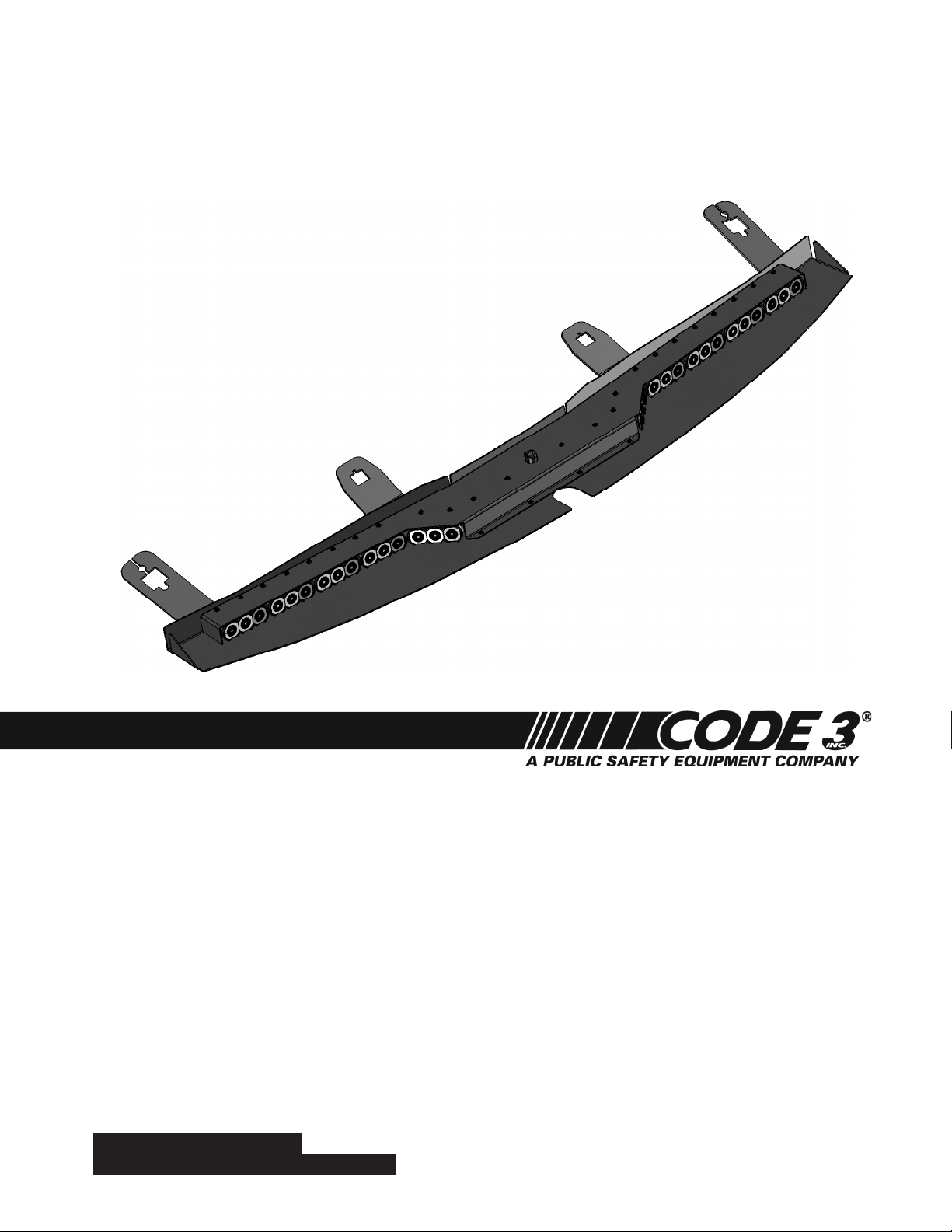
SUPERVISORTL™
SuperVisorTL™
Interior Lighting System
2011 Ford F150
CONTENTS:
Introduction ...........................................................................2
Unpacking & Pre-Installation ................................................2
Installation & Mounting ......................................................3-4
Wiring Instructions & Fusing .............................................4-5
Wiring Diagram .....................................................................5
LED Flash Pattern Selection & Troubleshooting ..................6
Exploded View & Parts List ..................................................7
Warranty ............................................................................... 8
For future reference, record your product's serial no. here __________________________________________
IMPORTANT:
Read all instructions and warnings before installing and using.
This manual must be delivered to the end user of this equipment.
INSTALLER:
Page 2

Introduction
The SuperVisor TL™ is an interior lighting system that ts in the visor area near the top of the windshield. The SuperVisor has room
for up to ten light heads.
Product Features
TL light head options: Red, Blue, Amber, and White------------------------------Flashing or Steady Burn Control
Size: 48.29" long x 2.00" tall x 8.04" deep--------------------------------------------------Weight: 7.5 lbs
The use of this or any warning device does not ensure that all drivers can or will observe or react to an
emergency warning signal. Never take the right-of-way for granted. It is your responsibility to be sure you can
proceed safely before entering an intersection, driving against trafc, responding at a high rate of speed, or
walking on or around trafc lanes. The effectiveness of this warning device is highly dependent upon correct
mounting and wiring. Read and follow the manufacturer’s instructions before installing or using this device. The
vehicle operator should insure daily that all features of the device operate correctly. In use, the vehicle operator
should insure the projection of the warning signal is not blocked by vehicle components (i.e.: open trunks or
compartment doors), people, vehicles, or other obstructions. This equipment is intended for use by authorized
personnel only. It is the user’s responsibility to understand and obey all laws regarding emergency warning
devices. The user should check all applicable city, state and federal laws and regulations. Code 3, Inc., assumes
no liability for any loss resulting from the use of this warning device. Proper installation is vital to the performance
of this warning device and the safe operation of the emergency vehicle. It is important to recognize that the
operator of the emergency vehicle is under psychological and physiological stress caused by the emergency
situation. The warning device should be installed in such a manner as to: A) Not reduce the output performance
of the system, B) Place the controls within convenient reach of the operator so that he can operate the system
without losing eye contact with the roadway. Emergency warning devices often require high electrical voltages
and/or currents. Properly protect and use caution around live electrical connections. Grounding or shorting of
electrical connections can cause high current arcing, which can cause personal injury and/or severe vehicle
WARNING!
damage, including re. Any electronic device may create or be affected by electromagnetic interference. After
installation of any electronic device operate all equipment simultaneously to insure that operation is free of
interference. Never power emergency warning equipment from the same circuit or share the same grounding
circuit with radio communication equipment. All devices should be mounted in accordance with the manufacturer's
instructions and securely fastened to vehicle elements of sufcient strength to withstand the forces applied to the
device. Driver and/or passenger air bags (SRS) will affect the way equipment should be mounted. This device
should be mounted by permanent installation and within the zones specied by the vehicle manufacturer, if any.
Any device mounted in the deployment area of an air bag will damage or reduce the effectiveness of the air
bag and may damage or dislodge the device. Installer must be sure that this device, its mounting hardware and
electrical supply wiring does not interfere with the air bag or the SRS wiring or sensors. Mounting the unit inside
the vehicle by a method other than permanent installation is not recommended as unit may become dislodged
during swerving, sudden braking or collision. Failure to follow instructions can result in personal injury. PROPER
INSTALLATION COMBINED WITH OPERATOR TRAINING IN THE PROPER USE OF EMERGENCY WARNING
DEVICES IS ESSENTIAL TO INSURE THE SAFETY OF EMERGENCY PERSONNEL AND THE PUBLIC.
Unpacking & Pre-installation
Carefully remove the SuperVisor and place it on a at surface, taking care not to scratch the lenses or damage the cable coming out of
the top. Examine the unit for transit damage, broken lamps, etc. Report any damage to the carrier and keep the shipping carton.
Standard light bars are built to operate on 12 volt D.C. negative ground (earth) vehicles. If you have an electrical system other than 12
volt D.C. negative ground (earth), and have not ordered a specially wired light bar, contact the factory for instructions.
Test the unit before installation. To test, touch the black wire to the ground (earth) and the other wires to +12 volts D.C., in accordance
with the instructions attached to the cable (an automotive battery is preferable for this test). A battery charger may be used, but note that
some electronic options may not operate normally when powered by a battery charger. If problems occur at this point, contact the factory.
Note: Before beginning the installation process, be absolutely certain
that the Light Bar functions as desired (See page 6 for options)!
WARNING!
Mounting Hardware - All mounting hardware is packed in a small bag inside the main carton. There are four brackets used to mount
the SuperVisor to the vehicle. These are discussed in detail later.
Utilizing non-factory supplied screws and/or mounting brackets and/or the improper
number of screws may result in loss of warranty coverage on the equipment.
2
Page 3
Installation and Mounting Instructions
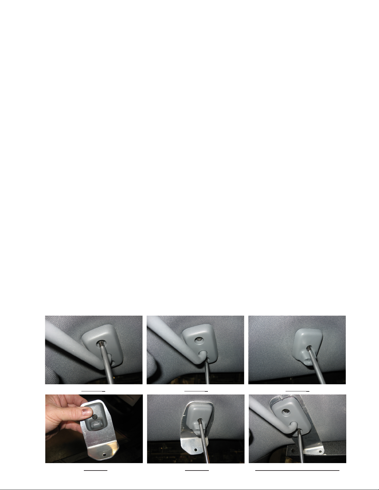
Step 1 Remove the (2) small Phillips screws as shown in Figures 1 and 2 from each pivot bracket. Pull the visor pivot brackets down
from the headliner and carefully allow the sun visors to hang by the vehicle's attached vanity mirror light wires if so equiped.
Step 2 Unscrew the single Phillips screw holding each of the vehicle's (2) inner visor clips in place as shown in Figure 3.
Step 3 Attach the vehicle's inner visor clips to the SuperVisor Inner Mounting Brackets as shown in Figure 4. Thread each of the vehi-
cles Phillips screws you removed in step 2 above all the way up into the vehicle's plastic inner visor clip (this makes it easier to see the
end of the screw so you can thread the screw into it's hole in the headliner). Position the SuperVisor Inner Mounting Brackets up to
the headliner as shown in gure 5 and loosely thread the screws into the screw hole in the vehicle's headliner. Tighten the screws until
the brackets are within about 1/8" of the headliner. Allow the brackets to remain loose and do not fully tighten the screws at this time.
Step 4 Attach the vehicle's plastic outer visor pivot brackets to the supplied SuperVisor Outer Mounting Brackets and thread the (2)
supplied #8 X 1" Black Phillips Truss Head Sheet Metal Screws as shown in Figure 6 (Drivers Side Shown). Note: Be very careful to
tuck the vanity mirror light wires, if so equiped up in the hole in the headliner and out of the way to avoid pinching the wires.
Tighten the mounting screws until the brackets are within about 1/8" of the headliner. Allow the brackets to remain loose and do not fully
tighten the screws at this time.
Step 5 Route the SuperVisor's cable to the desired side of the vehicle and out the end of the SuperVisor's Outer Panel. Make sure
the cable will not interfere with the vehicle's headliner and windshield as you position the SuperVisor up to the headliner in front of the
SuperVisor Inner and Outer Mounting Brackets as shown in Figure 7 page 4.
Step 6 Line up the slots in the SuperVisor Inner Mounting Brackets with the threaded holes in the SuperVisor, and thread the supplied
1/4"-20 screws and internal tooth lock washers through the slots and into the SuperVisor's Outer Panel (see Figure 8 page 4).
Step 7 Line up the slots in the SuperVisor's Outer Mounting Brackets with the threaded holes in the SuperVisor, and Thread the sup-
plied 1/4"-20 screws and internal tooth lock washers through the slot in the SuperVisor's Outer Mounting Brackets and into the SuperVisor's Outer Panel (see Figure 9 page 4).
Step 8 Make sure the SuperVisor is exactly centered in the vehicle and tighten all (4) of the #8 X 1" Black Phillips Truss Head Sheet
Metal Screws in the Outer Mounting Brackets and the vehicle's (2) small Phillips screws in the Inner Mounting Brackets (See Figure 10
page 4 for the Outer Mounting Brackets see Figure 11 page 4 for the Inner Mounting Brackets).
Step 9 While pushing the SuperVisor very tightly up against the headliner, tighten the (2) 1/4"-20 SuperVisor Inner Mounting Bracket
screws as shown in Figure 12 then again while pushing the SuperVisor very tightly up against the headliner, tighten the (2) 1/4"-20
SuperVisor Outer Mounting Bracket screws as shown in Figure 13 page 4. Note: It is best to have an assistant push up on the
SuperVisor while you tighten the screws to assure that the SuperVisor is tight against the vehicle's headliner.
FIGURE 1 FIGURE 2 FIGURE 3
FIGURE 4 FIGURE 5 FIGURE 6-DRIVER SIDE SHOWN
3
Page 4

Installation and Mounting Instructions: Cont.
FIGURE 7 FIGURE 8 FIGURE 9
FIGURE 10 FIGURE 11 FIGURE 12
FIGURE 13
This unit must be mounted within the interior passenger compartment of the vehicle only. It is not intended for
use in exterior applications. All devices should be mounted in accordance with the manufacturer’s instructions
and securely fastened to vehicle elements of sufcient strength to withstand the forces applied to the device.
Driver and/or passenger air bags (SRS) will affect the way equipment should be mounted. This device should
be mounted by permanent installation and within the zones specied by the vehicle manufacturer, if any. Any
WARNING:
device mounted in the deployment area of an air bag will damage or reduce the effectiveness of the air bag and
may damage or dislodge the device. Installer must be sure that this device, its mounting hardware and electrical supply wiring does not interfere with the air bag or the SRS wiring or sensors. Mounting the unit inside
the vehicle by a method other than permanent installation is not recommended as unit may become dislodged
during swerving, sudden braking or collision. Failure to follow instructions can result in personal injury.
Caution: Drilling into the housing of the light bar could damage wiring or other internal
components.
Wiring Instructions
Finish routing the cable as desired. It is advisable to leave an extra loop of cable when installing the light bar to allow for future
changes or reinstallations. Connect the black lead to a solid frame ground (earth), preferably the (-) or ground (earth) side of the
battery, and the power wire to the +12V terminal of the battery. Connect the remaining wires as shown on page 5.
4
Page 5

PASSENGER
SIDE
DRIVER
SIDE
LT BLUE
PURPLE
WHITE
RED
ORANGE
GREEN/WHT
BROWN
BROWN/WHT
BLACK----------NEGATIVE GROUND
BLUE/WHT---------NOT USED
GREEN------------NOT USED
YELLOW-----------NOT USED
FUSE SIZE CALCULATION:
USE .5 AMP FOR EACH LED HEAD
WIRING DIAGRAM
PINK
RED/WHITE
WARNING!
Larger wires and tight connections will provide longer service life for components. For high current wires it
is highly recommended that terminal blocks or soldered connections be used with shrink tubing to protect
the connections. Do not use insulation displacement connectors (e.g. 3M® Scotchlock type connectors).
Route wiring using grommets and sealant when passing through compartment walls. Minimize the
number of splices to reduce voltage drop. High ambient temperatures (e.g. under hood) will signicantly
reduce the current carrying capacity of wires, fuses, and circuit breakers. Use "SXL" type wire in engine
compartment. All wiring should conform to the minimum wire size and other recommendations of the
manufacturer and be protected from moving parts and hot surfaces. Looms, grommets, cable ties, and
similar installation hardware should be used to anchor and protect all wiring. Fuses or circuit breakers
should be located as close to the power takeoff points as possible and properly sized to protect the wiring
and devices. Particular attention should be paid to the location and method of making electrical connections
and splices to protect these points from corrosion and loss of conductivity. Ground terminations should
only be made to substantial chassis components, preferably directly to the vehicle battery. The user should
install a fuse sized to approximately 125% of the maximum Amp capacity in the supply line to protect
against short circuits. For example, a 30 Amp fuse should carry a maximum of 24 Amps. DO NOT USE
1/4" DIAMETER GLASS FUSES AS THEY ARE NOT SUITABLE FOR CONTINUOUS DUTY IN SIZES
ABOVE 15 AMPS. Circuit breakers are very sensitive to high temperatures and will "false trip" when
mounted in hot environments or operated close to their capacity.
LED Fusing Considerations
Although the average current draw per module is very low, due to the type of circuit used to power each module, the instantaneous peak current to a module can be signicantly higher during low voltage conditions. To avoid prematurely blowing
ATO style fuses or tripping breakers it is recommended the following rule-of-thumb be used to size fuses or breakers. This is
especially important in lightbars with many LED modules running off a single fused source.
Minimum fuse size calculation: (See Wiring Diagram page 5)
For LED 12 volt electrical current only
.5 X (number of 3 LED modules being fused) = Total Electrical Current at 12.8 VDC
WARNING!
This Product contains high intensity LED devices. To prevent eye damage,
DO NOT stare into light beam at close range.
5
Page 6

Changing Flash Patterns
To change the ash patterns on the LED Light Heads, remove the mounting screws that attach the SuperVisor's Cover to the Outer
Panel to gain access to the printed circuit boards inside (see the exploded view on page 7). Momentarily short and release the pattern change prongs as shown below to change patterns. Carefully replace the SuperVisor's Cover over the Outer Panel and replace
the Cover Mounting Screws.
Note: Be extremely careful to replace the wiring such that you don't pinch a wire when you replace the SuperVisor's Cover. Test the unit to be sure that it works properly.
Directional module Flash Pattern - Table 2
CycleFlash (DEFAULT) Quad Pop Flash75
NFPA QuadFlash75 Triple Pop Flash75
Steadyburn SingleFlash375
ModelFlash SingleFlash250
ActiveFlash SingleFlash150
FiveFlash70 FiveFlash150
QuadFlash70 QuadFlash150
TripleFlash70 DoubleFlash150
DoubleFlash70 TripleFlash150
SingleFlash75
Momentarily short and release
to change patterns
J1
PCB
Flash Pattern Header for OPTIX
Troubleshooting
All SuperVisorTLs are thoroughly tested prior to shipment. However, should you encounter a problem during installation or during the
life of the product, follow the guide below for information on repair and troubleshooting. Additional information may be obtained from
the factory technical help line at 314-996-2800.
Follow the guide below for information on repair and troubleshooting.
TROUBLESHOOTING GUIDE
Note: LED modules must be replaced as a module. There are no user serviceable parts.
PROBLEM
LED module not
operating when
powered.
QUESTIONS POSSIBLE CAUSE
N/A
a. Bad power/ground
connection.
b. Defective module.
6
SOLUTION
a. Fix connection.
b. Replace module
Page 7

Parts List
1
2
3
4
5
6
Reference Number Part Description Part Number
1 Outer Mtg. Brkt. Ford F150 Pass Side T15465
2 Chassis TL-Ford F150 T15462
3 Inner Mtg. Brkt. Ford F150 T15460
4 Outer Mtg. Brkt. Ford F150 Drivr Side T15464
5 Outer Panel-Ford F150 T15457
6 OPTIX Module Contact Code 3, Inc for P/N
Note: Some of the above listed parts may not be available for purchase!
7
Page 8

WARRANTY
Code 3, Inc.'s emergency devices are tested and found to be operational at the time of manufacture. Provided
they are installed and operated in accordance with manufacturer's recommendations, Code 3, Inc. guarantees all
parts and components except the lamps to a period of 1 year, LED Lighthead modules to a period of 5 years (unless
otherwise expressed) from the date of purchase or delivery, whichever is later. Units demonstrated to be defective
within the warranty period will be repaired or replaced at the factory service center at no cost.
Use of lamp or other electrical load of a wattage higher than installed or recommended by the factory, or use
of inappropriate or inadequate wiring or circuit protection causes this warranty to become void. Failure or destruction
of the product resulting from abuse or unusual use and/or accidents is not covered by this warranty. Code 3, Inc.
shall in no way be liable for other damages including consequential, indirect or special damages whether loss is due
to negligence or breach of warranty.
CODE 3, INC. MAKES NO OTHER EXPRESS OR IMPLIED WARRANTY INCLUDING, WITHOUT LIMITA-
TION, WARRANTIES OF FITNESS OR MERCHANTABILITY, WITH RESPECT TO THIS PRODUCT.
PRODUCT RETURNS
If a product must be returned for repair or replacement*, please contact our factory to obtain a Return
Goods Authorization Number (RGA number) before you ship the product to Code 3, Inc. Write the RGA number
clearly on the package near the mailing label. Be sure you use sufcient packing materials to avoid damage to
the product being returned while in transit.
*Code 3, Inc. reserves the right to repair or replace at its discretion. Code 3, Inc. assumes no responsibility or liability for expenses incurred for the removal and /or
reinstallation of products requiring service and/or repair.; nor for the packaging, handling, and shipping: nor for the handling of products returned to sender after the service has been
rendered.
NEED HELP? Call our Technical Assistance HOTLINE - (314) 996-2800
St. Louis, Missouri 63114-2029—USA
Ph. (314) 426-2700 Fax (314) 426-1337
10986 N. Warson Road
www.code3pse.com
Code 3®, Inc.
Code 3 is a registered trademark of Code 3, Inc. a Public Safety Equipment Company.
Revision 0, 09/11 - Instruction Book Part No. T15467
©2011 Public Safety Equipment, Inc. Printed in USA
8
 Loading...