

Page 1

INSTALLATION MANUALS FOR THE SUPERVISOR
Click below to go to the appropriate model. For all others, contact Customer Service at
(314) 426-2700.
Ford Crown Victoria
Chevy Impala
Ford Explorer
Chevy Tahoe
Page 2
INSTALLATION
& OPERATION
MANUAL
SUPERVISOR™
SuperVisor™
Interior Lighting System
Ford Crown Victoria
Including 2005 Model
CONTENTS:
Introduction..........................................................................2
Unpacking & Pre-Installation...............................................3
Installation & Mounting .....................................................3-7
Wiring Diagram & Instructions .......................................... 8-9
Fusing and MR8 Lamp Installation.................................... 10
LED Flash pattern selection & Troubleshooting............... 11
Exploded View & Parts List.............................................. 12
Notes............................................................................ 13 -15
Warranty ............................................................................ 16
For future reference record your product's serial no. here __________________________________________
Read all instructions and warnings before installing and using.
INSTALLER:
This manual must be delivered to the end user of this equipment.IMPORTANT:
Page 3

Introduction
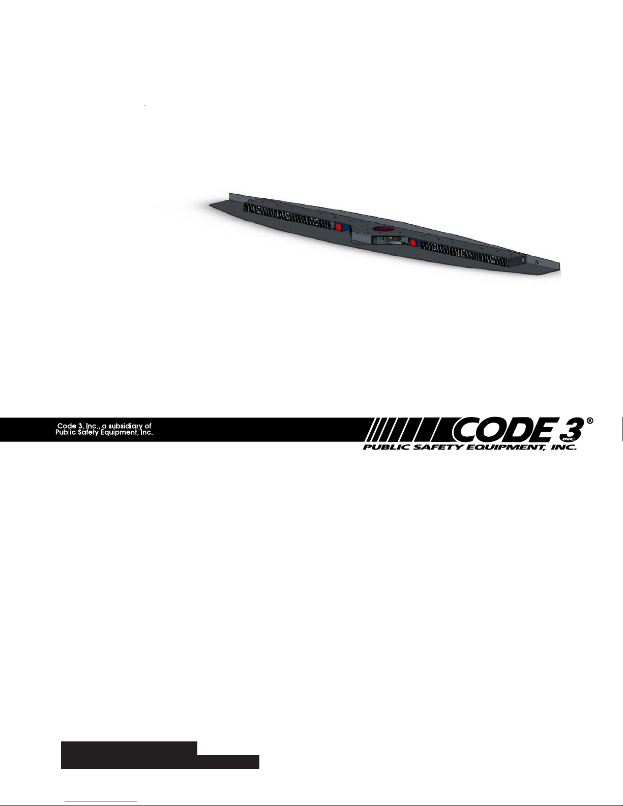
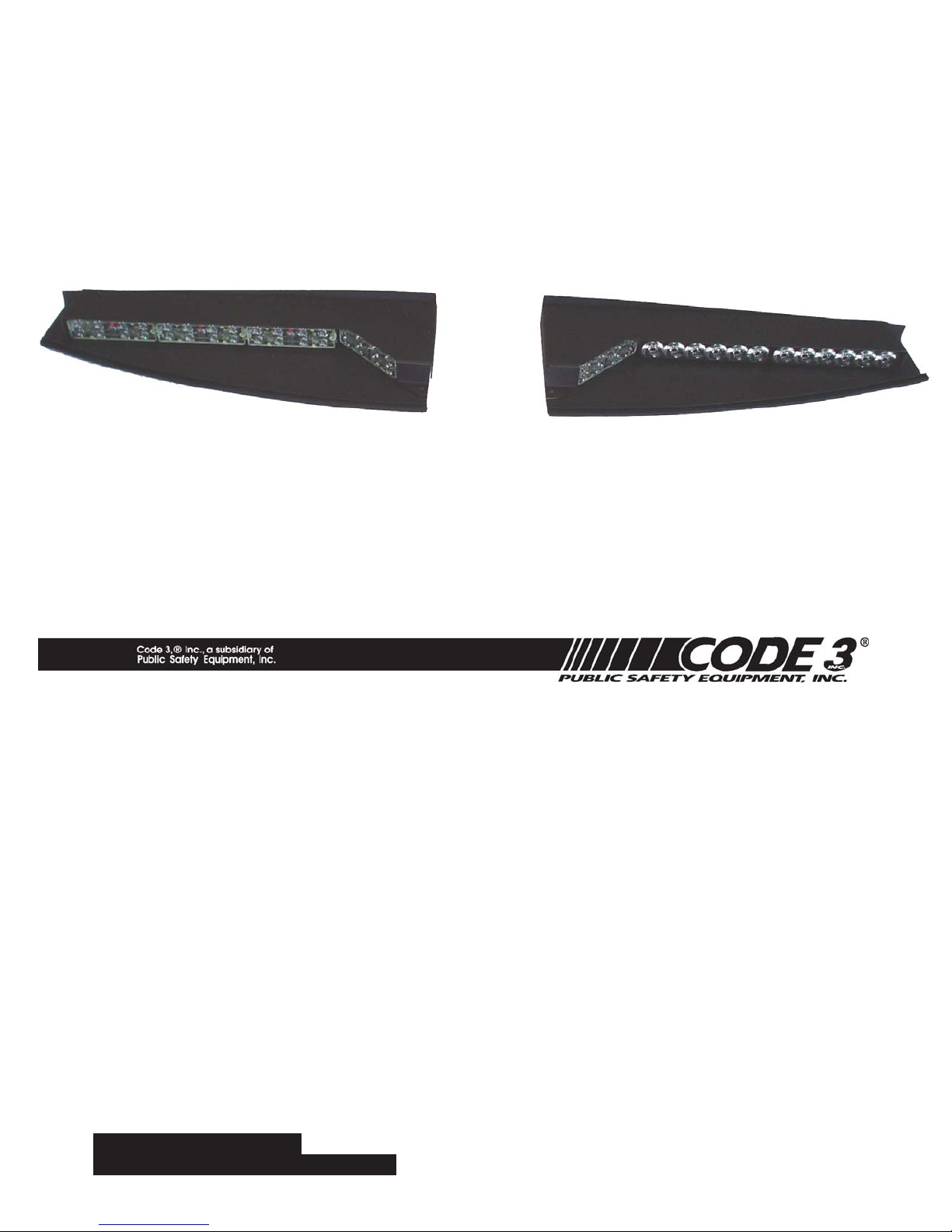
The SuperVisor™ is an interior lighting system that fits in the visor area near the top of the windshield. It delivers an amazing warning
signal, including MR8 powered takedown lights.
The SuperVisor is designed on a modular basis, which means that the light bar can be customized to meet most any requirements.
The SuperVisor has room for up to eight LED lightheads plus two MR8 takedowns. Each lighthead is individually wired for any flash
pattern or combination of flash patterns required.
The use of this or any warning device does not ensure that all drivers can or will observe or react to an emergency
warning signal. Never take the right-of-way for granted. It is your responsibility to be sure you can proceed safely
before entering an intersection, driving against traffic, responding at a high rate of speed, or walking on or around
traffic lanes.
The effectiveness of this warning device is highly dependent upon correct mounting and wiring. Read and follow
the manufacturer’s instructions before installing or using this device. The vehicle operator should insure daily that all
features of the device operate correctly. In use, the vehicle operator should insure the projection of the warning
signal is not blocked by vehicle components (i.e.: open trunks or compartment doors), people, vehicles, or other
obstructions.
This equipment is intended for use by authorized personnel only. It is the user’s responsibility to understand and
!
WARNING!
obey all laws regarding emergency warning devices. The user should check all applicable city, state and federal
laws and regulations.
Code 3, Inc., assumes no liability for any loss resulting from the use of this warning device.
Proper installation is vital to the performance of this warning device and the safe operation of the emergency
vehicle. It is important to recognize that the operator of the emergency vehicle is under psychological and physiological stress caused by the emergency situation. The warning device should be installed in such a manner as to:
A) Not reduce the output performance of the system, B) Place the controls within convenient reach of the operator
so that he can operate the system without losing eye contact with the roadway.
Emergency warning devices often require high electrical voltages and/or currents. Properly protect and use caution
around live electrical connections. Grounding or shorting of electrical connections can cause high current arcing,
which can cause personal injury and/or severe vehicle damage, including fire.
Any electronic device may create or be affected by electronmagnetic interference. After installation of any electronic
device operate all equipment simultaneously to insure that operation is free of interference. Never power emergency warning equipment from the same circuit or share the same grounding circuit with radio communication
equipment.
PROPER INSTALLATION COMBINED WITH OPERATOR TRAINING IN THE PROPER USE OF EMERGENCY
WARNING DEVICES IS ESSENTIAL TO INSURE THE SAFETY OF EMERGENCY PERSONNEL AND THE
PUBLIC.
All devices should be mounted in accordance with the manufacturer's instructions and securely fastened to vehicle
elements of sufficient strength to withstand the forces applied to the device. Driver and/or passenger airbags (SRS)
will affect the way equipment should be mounted. This device should be mounted by permanent installation and
within the zones specified by the vehicle manufacturer, if any. Any device mounted in the deployment area of an air
bag will damage or reduce the effectiveness of the air bag and may damage or dislodge the device. Installer must
be sure that this device, its mounting hardware and electircal supply wiring does not interfere with the air bag or the
SRS wiring or sensors. Mounting the unit inside the vehicle by a method other than permanent installation is not
recommended as unit may become dislodged during swerving, sudden braking or collision. Failure to follow
instructions can result in personal injury.
2
Page 4
Unpacking & Pre-installation
Carefully remove the SuperVisor™ and place it on a flat surface, taking care not to scratch the lenses or damage the cable coming out of the
side. Examine the unit for transit damage, broken lamps, etc. Report any damage to the carrier and keep the shipping carton.
Standard light bars are built to operate on 12 volt D.C. negative ground (earth) vehicles. If you have an electrical system other than 12
volt D.C. negative ground (earth), and have not ordered a specially wired light bar, contact the factory for instructions.
Test the unit before installation. To test, touch the black wire to the ground (earth) and the other wires to +12 volts D.C., in accordance with
the instructions attached to the cable (an automotive battery is preferable for this test). Some units may be factory wired for control by a LED
flasher in which case the cable's wire tag should be consulted. A battery charger may be used, but please note that some electronic options
(flashers, stingrays, etc.) may not operate normally when powered by a battery charger. If problems occur at this point, contact the factory.
Utilizing non-factory supplied screws and/or mounting brackets and/or the improper number
WARNING!
Mounting Hardware - All mounting hardware is packed in a small box inside the main carton. There are four brackets used to mount
the visor bar to the vehicle. These are discussed in detail later.
!
Removing Sun Visors
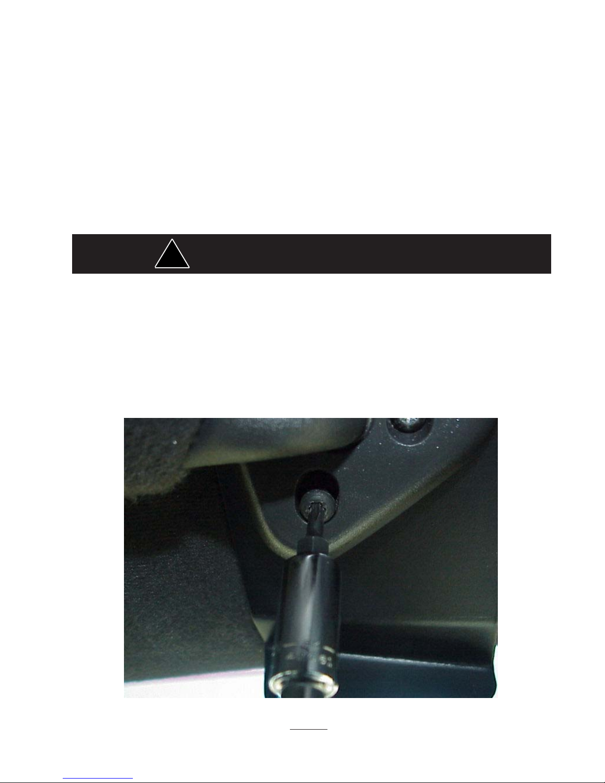
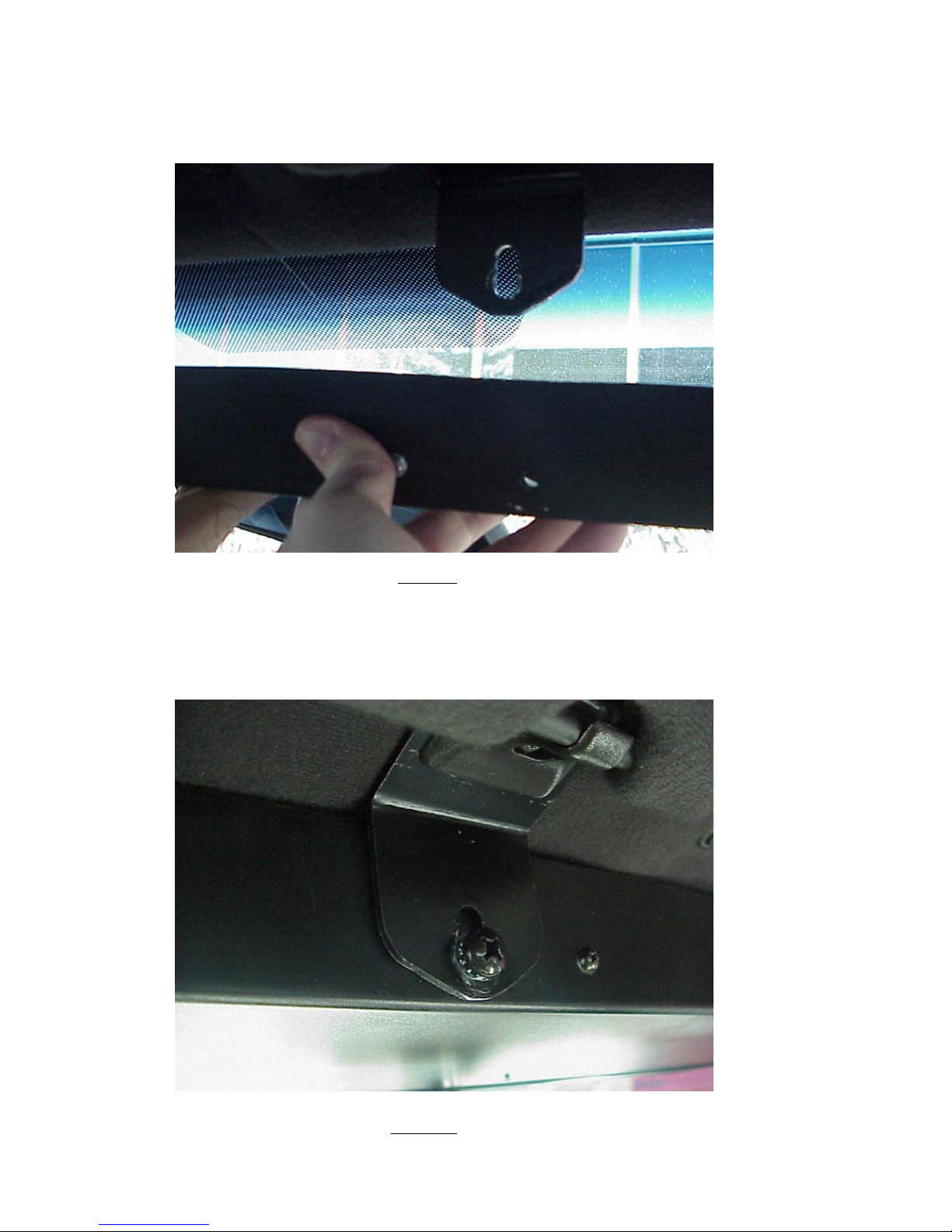
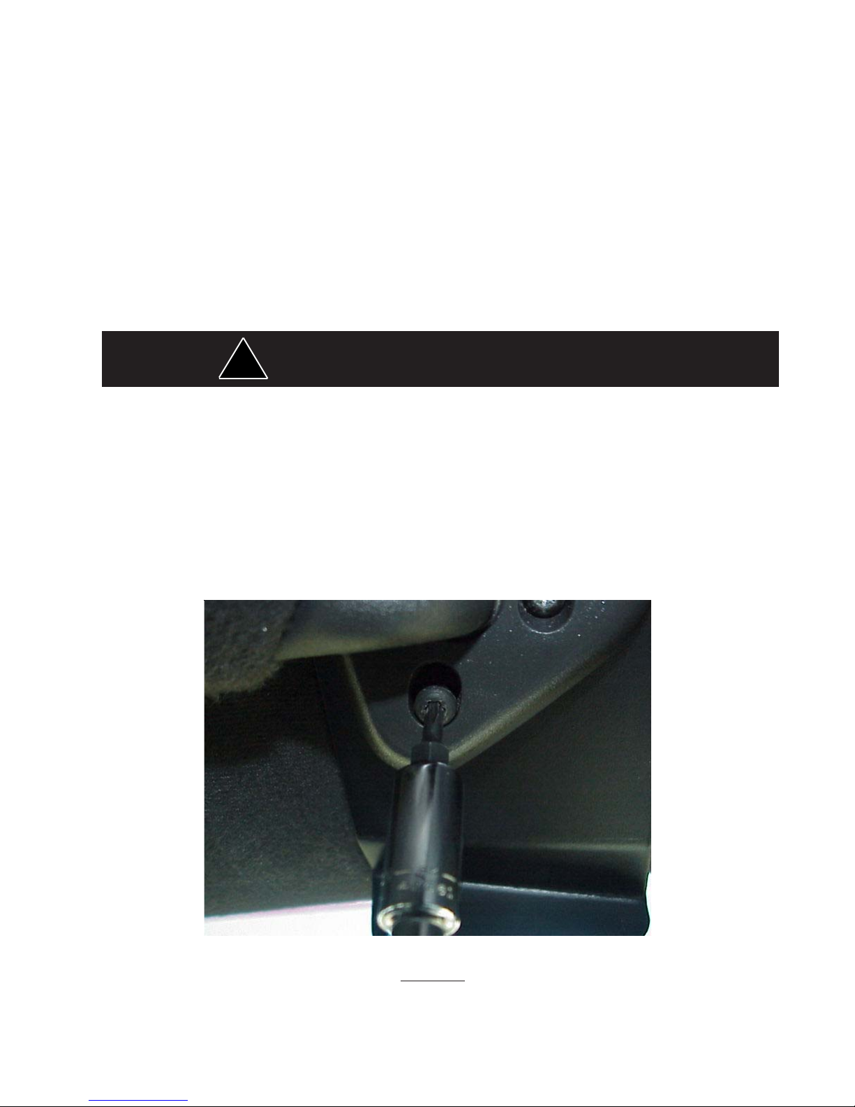
Begin the installation by removing the Crown Victoria's driver and passenger sun visors. Identify each visor with tape or other
marking to indicate the driver from the passenger side unit. They are not identical. There are three screws that hold the pivotal
arm of the sun visor to the headliner. Remove each screw using a small torx screwdriver starting with the lower screw as shown in
Figure 1. Then unclip the sun visor and rotate it over to expose the two upper screws.
of screws may result in loss of warranty coverage on the equipment.
FIGURE 1
3
Page 5
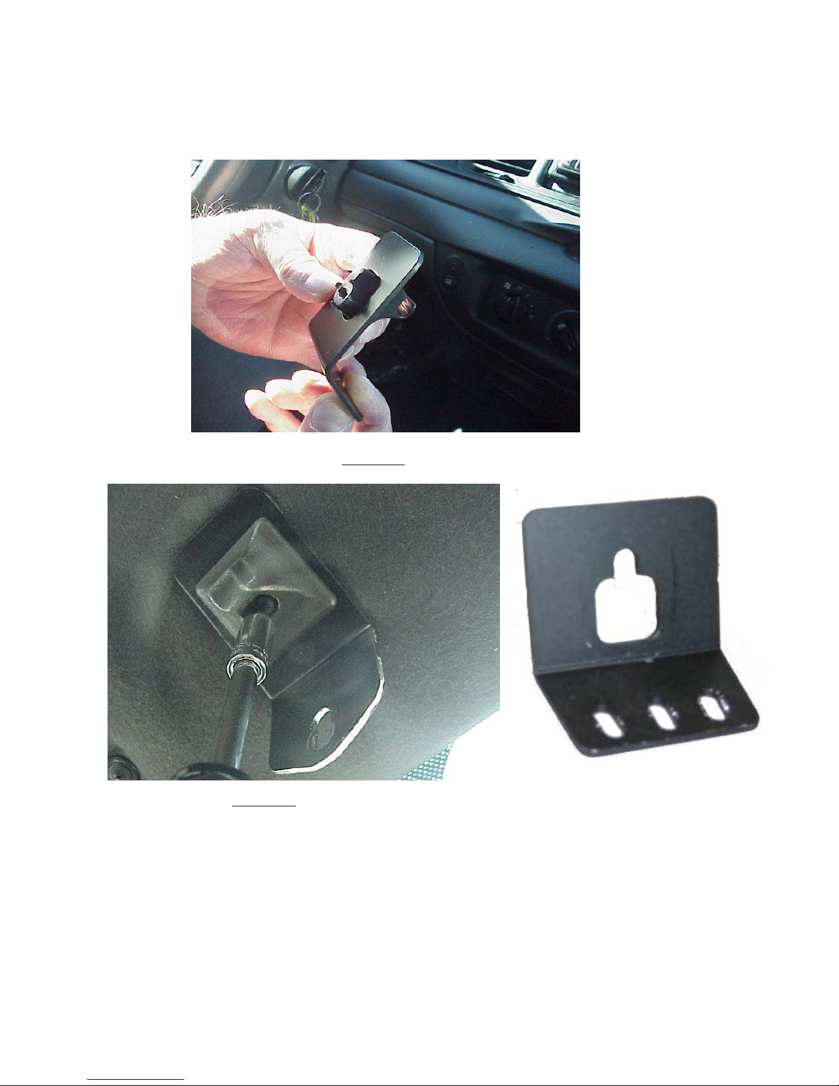
Attach brackets to sun visor retaining clips
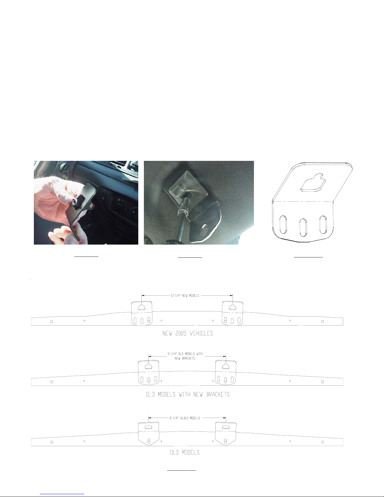
In order to remove the sun visor retaining clip, unscrew the one torx screw holding it in place. Place the inner bracket on the retaining
clip as shown in Figure 2. Attach to the inner bracket and retaining clip to the headliner as illustrated in Figure 3. Do not tighten these
screws at this time.
the Crown Vic. To confirm that you have a 2005 vehicle with the changes, measure the distance between the mounting screws
fastening the two inner sun visor clips, if the distance between the clips measures 11 1/4" the vehicle was built before the
change, if the distance measures 13 1/4" it is the new 2005 version and has the change
Figure 3 are for vehicles built before the change and will not work for the newer vehicles. The inner mounting brackets shown
in Figure 3A will work in both the new and old vehicles. The basic installation is the same except when mounting the
SuperVisor to the inner brackets install the 1/4-20 x1/2" mounting screws into the slot in the inner mounting bracket that is
nearest the mating hole in the SuperVisor's Outer panel see Figure 3B.
Note: Some time between January 1st and January 10th of 2005, Ford made changes to the 2005 model of
. The inner mounting brackets shown in
FIGURE 2
FIGURE 3
FIGURE 3A
FIGURE 3B
Page 6
Attaching the pivot arm brackets
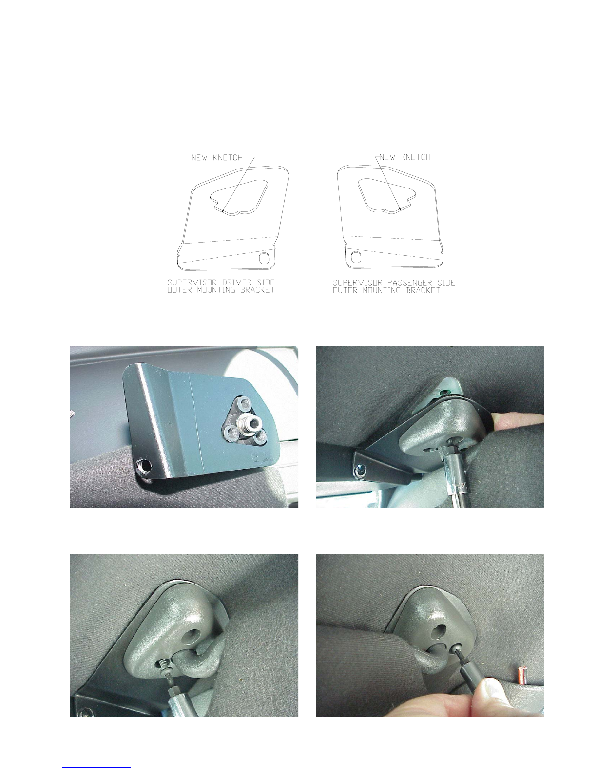
Attach the outer brackets that are supplied noting the difference between passenger and driver side brackets (see Figure 4).
Position the bracket on the passenger sun visor's pivot arm as shown in Figure 5. Rotate the pivot arm on the passenger sun visor
and verify the orientation of the bracket as shown in Figure 6. Note that the thicker portion of the pivot arm hinge aligns to the upper
inside hole. Attach the first two torx screws as shown in Figure 6 and Figure 7. Next, move the sun visor over in order to gain access
to install the final screw into the lower position as shown in Figure 8. Repeat this operation for the driver sun visor and outer bracket.
FIGURE 4
FIGURE 5
FIGURE 7 FIGURE 8
FIGURE 6
Page 7
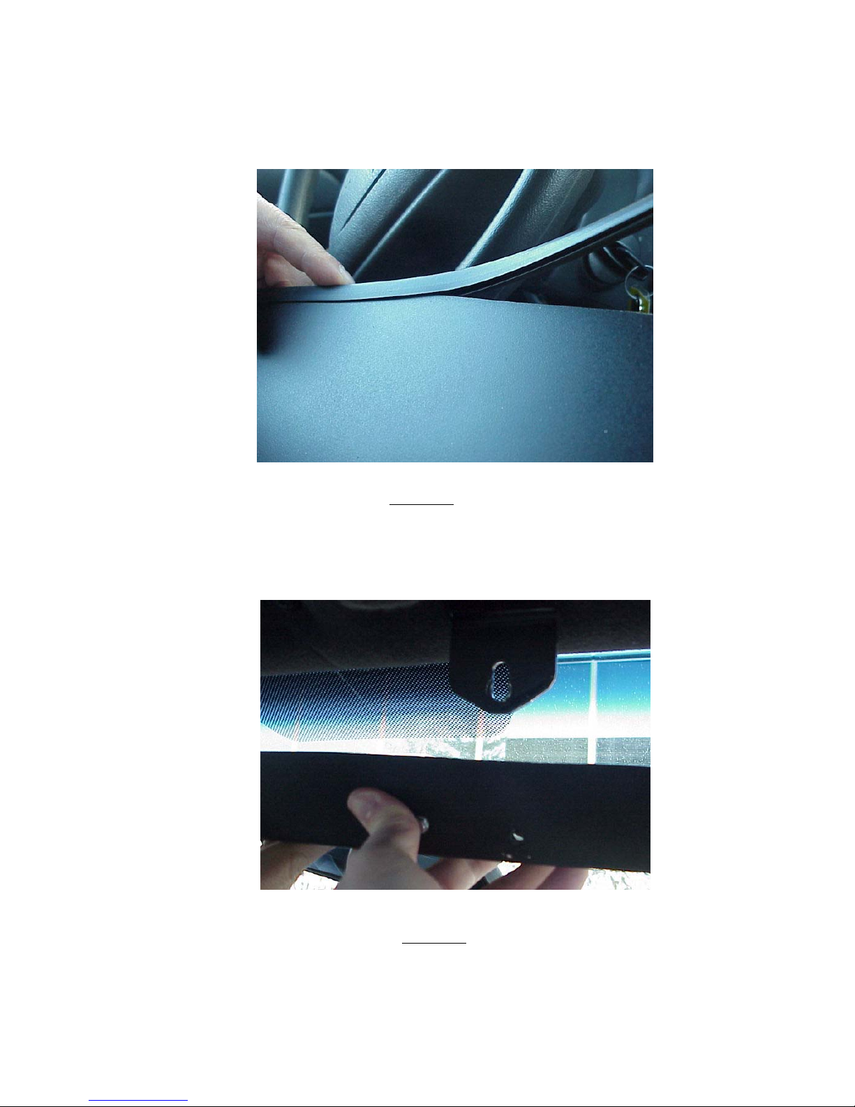
Mounting the SuperVisor™
Once all four brackets and sun visors are attached, the SuperVisor is now ready to be installed. Position the SuperVisor in the
center of the windshield as shown in Figure 9.
FIGURE 9
The two center brackets should line up with the holes in the SuperVisor's lower chassis. Using the supplied 1/4"-20 bolts and internal
tooth lock washers, loosely install them as shown in Figure 10.
FIGURE 10
6
Page 8

Mounting the SuperVisor™(continued)
Next, if necessary, slightly loosen the three pivot arm bracket and sun visor retaining clip torx screws in order to align the pivot arm
bracket's hole with the mating chassis hole on the end of the SuperVisor. Finally, thread the supplied bolts and the internal tooth
lock washers through the pivot arm bracket's hole into the hole on the end of the chassis, shown in Figure 11. Tighten all pivot arm
and sun visor retaining clip torx screws.Using a tape measure and a level, center the SuperVisor from side to side and locate a
position on the headliner where the SuperVisor is level. Finally, tighten all four bolts securely. Do not overtighten.
FIGURE 11
Caution: The bracket fasteners make excellent hard mounting points for radar guns and
video cameras etc. Drilling into the housing of the light bar could damage wiring or
other internal components.
7
Page 9
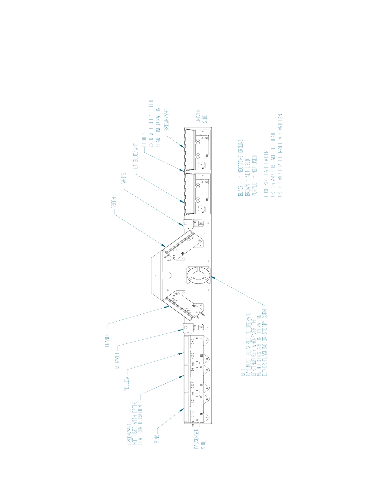
Wiring Diagram
8
Page 10

Wiring Instructions
Larger wires and tight connections will provide longer service life for components. For high current wires it is
highly recommended that terminal blocks or soldered connections be used with shrink tubing to protect the
!
WARNING!
connections. Do not use insulation displacement connectors (e.g. 3M® Scotchlock type connectors). Route
wiring using grommets and sealant when passing through compartment walls. Minimize the number of splices to
reduce voltage drop. High ambient temperatures (e.g. underhood) will significantly reduce the current carrying
capacity of wires, fuses, and circuit breakers. Use "SXL" type wire in engine compartment. All wiring should
conform to the minimum wire size and other recommendations of the manufacturer and be protected from moving
parts and hot surfaces. Looms, grommets, cable ties, and similar installation hardware should be used to
anchor and protect all wiring. Fuses or circuit breakers should be located as close to the power takeoff points as
possible and properly sized to protect the wiring and devices. Particular attention should be paid to the location
and method of making electrical connections and splices to protect these points from corrosion and loss of
conductivity. Ground terminations should only be made to substantial chassis components, preferably directly to
the vehicle battery. The user should install a fuse sized to approximately 125% of the maximum Amp capacity in
the supply line to protect against short circuits. For example, a 30 Amp fuse should carry a maximum of 24
Amps. DO NOT USE 1/4" DIAMETER GLASS FUSES AS THEY ARE NOT SUITABLE FOR CONTINUOUS
DUTY IN SIZES ABOVE 15 AMPS. Circuit breakers are very sensitive to high temperatures and will "false trip"
when mounted in hot environments or operated close to their capacity.
Route the wiring cable into the passenger compartment as shown in Figure 12. It is advisable to leave an extra loop of cable
when installing the light bar to allow for future changes or reinstallations. Connect the black lead to a solid frame ground
(earth), preferably, the (-) or ground (earth) side of the battery, and the remaining power wires to the +12V terminal of the
battery, power switches, siren or RLS controller. The MR8 takedowns may be installed to a flasher. The fan should be wired to
operate continuously whenever the takedowns are in operation, either flashing or steady burn. Each light head is wired
independently to allow complete flexibility of control.
FIGURE 12
9
Page 11
LED Fusing Considerations
Although the average current draw per module is very low, due to the type of circuit used to power each module, the
instantaneous peak current to a module can be significantly higher during low voltage conditions. To avoid prematurely blowing
ATO style fuses or tripping breakers it is recommended the following rule-of-thumb be used to size fuses or breakers. This is
especially important in light bars with many LED modules running off a single fused source,
Minimum fuse size calculation:
For LED 12 volt electrical current only
1.5 x (number of modules being fused)
Example: 2 intersection modules and 6 directional modules.
Minimum fuse requirement for single fuse - 1.5 (8) = 12 A
For MR8 takedown and fan 12 volt electrical current only
Total wattage (1 MR8's = 35W, fan = 5W) divided 12volts = Amperage
Example:2 MR8's and 1 fan = (75W/12) = 6.25 A
Total 12 volt electrical current
12A (for LED's) + 6.25A (for MR8's and fan) = 18.25 A
Product Features
LED-X light head options: Red, Blue, Amber, White;
Directional or Wide Optics;
Flashing or Steady Burn Control
6 LED Optix light head options: Red, Blue, Amber, White;
Directional or Wide Optics;
Flashing or Steady Burn Control
3 LED Optix light head options: Red, Blue, Amber, White;
Directional, Wide or Hybrid Optics;
Flashing or Steady Burn Control
33 Optix light head options: Two 3-LED Heads with one 6-LED Optic
Red, Blue, Amber, White;
Directional , Wide or Hybrid Optics;
Flashing or Steady Burn Control
LC-LED light head options: Red, Blue, Amber;
Flashing or Steady Burn Control
MR8 Specs: 35w Halogen with 13° spot
Size: 45.50" long x 2.00" tall x 7.25" deep
Weight: 7.5 lb
WARNING!
!
This Product contains high intensity LED devices. To prevent eye damage, DO NOT stare
into light beam at close range.
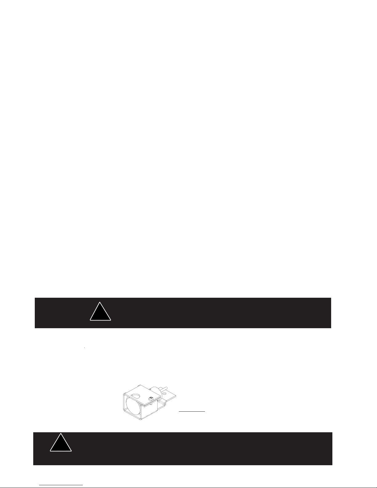
MR8 Takedown Light Assembly
Refer to Figure 13 for lamp replacement. Remove the lamp assembly from the product by disconnecting the two electrical wires and
removing the appropriate fastener. Remove the fastener clamping the lamp and then remove the lamp from the mounting bracket.
Disconnect the lamp from the ceramic connector and reinstall a new lamp. The lamp lens should be cleaned to remove fingerprints
then reinstall the lamp assembly in the light bar and reconnect the electrical wires. Reassemble the components in reverse order.
Lamps are extremely hot! Allow to cool completely before attempting to remove. Gloves and
!
eye protection should be worn when handling halogen lamps as they are pressurized and
accidental breakage can result in flying glass.
FIGURE 13
10
Page 12
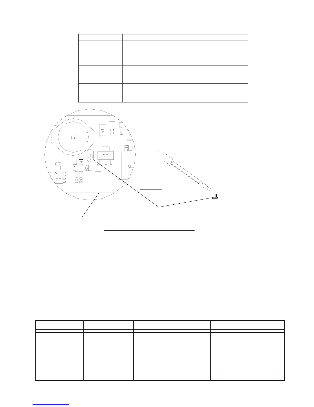
Directional module Flash Pattern - Table 2
Flash Pattern Description
Cycle Flash Cycles through various patterns @ 70 fpm
Steady-Burn Steady-Burn
Five Flash Five Pulses per flash @ 70 fpm
Quad Flash Four Pulses per flash @ 70 fpm
Triple Flash Three Pulses per flash @ 70 fpm
Double Flash Two Pulses per flash @ 70 fpm
Fast Double Flash Two Pulses per flash @ 85 fpm
NFPA Four Pulses, 70% Duty Cycle @ 75 fpm
Quad Pop Flash Four Pulses per flash ( 3 equal, 1 extended) @ 70 fpm
Triple Pop Flash Three Pulses per flash ( 2 equal, 1 extended) @ 70 fpm
Momentarily short and release
to change patterns
FIGURE 33
J1
PCB
Flash Pattern Header for OPTIX/LEDX
Troubleshooting
All SuperVisors are thoroughly tested prior to shipment. However, should you encounter a problem during installation or during the
life of the product, follow the guide below for information on repair and troubleshooting. Additional information may be obtained from
the factory technical help line at 314-996-2800.
Follow the guide below for information on repair and troubleshooting.
TROUBLESHOOTING GUIDE
Note: LED modules must be replaced as a module. There are no user serviceable parts.
PROBLEM
QUESTIONS POSSIBLE CAUSE
SOLUTION
LED module not
operating when
powered.
N/A
a. Bad power/ground
connection.
b. Defective module.
11
a. Fix connection.
b. Replace module
Page 13
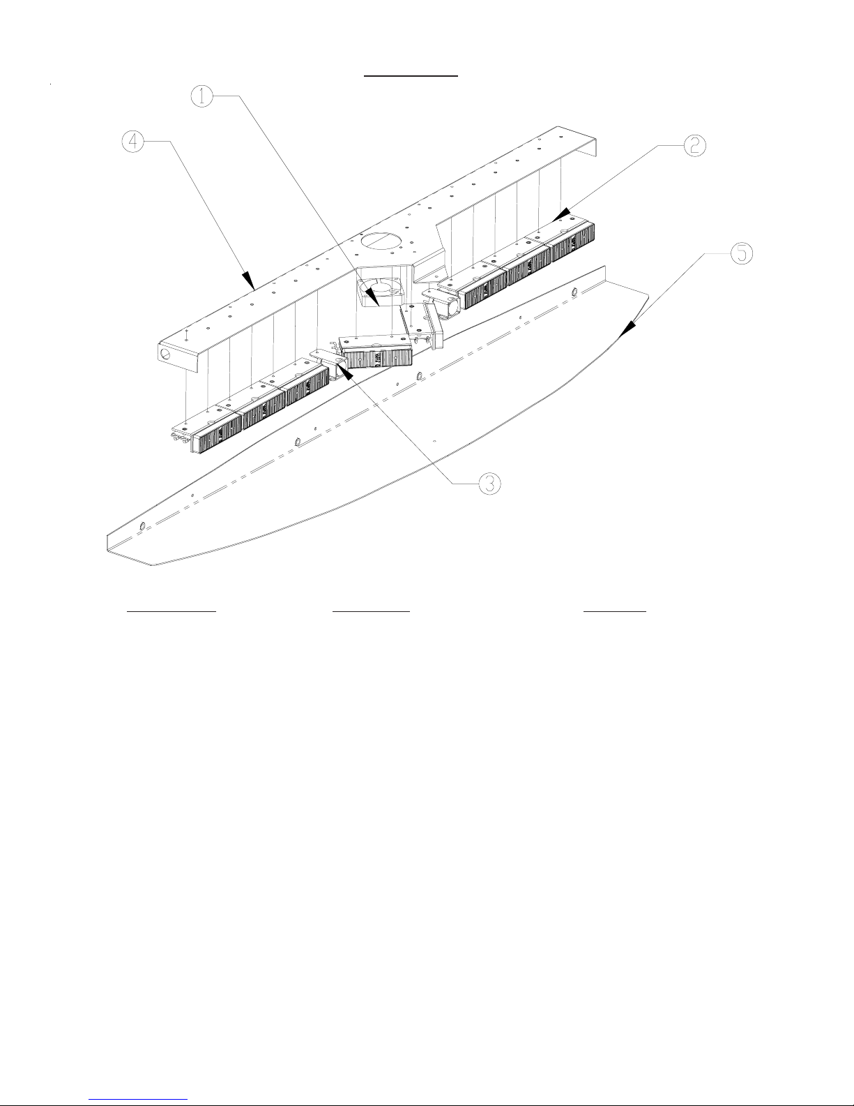
Parts List
Reference Number Part Description Part Number
1 +12V Cooling Fan T05612
2 *LED Module *Contact Code 3, Inc for P/N
3 MR8 lamp T09600
4 Chassis T09618
5 Outer Panel T09625
5 Outer Panel 2005 T09799
Not Shown Inner Mtg. Brkt. Crown Vic T09607
Not Shown Inner Mtg. Brkt. Crown Vic 2005 T09796
Not Shown Outer Mtg. Brkt. Crown Vic Pass T09608
Not Shown Outer Mtg. Brkt. Crown Vic Dr. T09610
Not Shown Outer Mtg. Brkt. Crown Vic Pass 2005 T09797
Not Shown Outer Mtg. Brkt. Crown Vic Dr.2005 T09798
12
Page 14

WARRANTY
Code 3, Inc.'s emergency devices are tested and found to be operational at the time of manufacture. Provided
they are installed and operated in accordance with manufacturer's recommendations, Code 3, Inc. guarantees all parts
and components except the lamps to a period of 1 year, LED Lighthead modules to a period of 5 years (unless otherwise
expressed) from the date of purchase or delivery, whichever is later. Units demonstrated to be defective within the
warranty period will be repaired or replaced at the factory service center at no cost.
Use of lamp or other electrical load of a wattage higher than installed or recommended by the factory, or use of
inappropriate or inadequate wiring or circuit protection causes this warranty to become void. Failure or destruction of
the product resulting from abuse or unusual use and/or accidents is not covered by this warranty. Code 3, Inc. shall
in no way be liable for other damages including consequential, indirect or special damages whether loss is due to
negligence or breach of warranty.
CODE 3, INC. MAKES NO OTHER EXPRESS OR IMPLIED WARRANTY INCLUDING, WITHOUT
LIMITATION, WARRANTIES OF FITNESS OR MERCHANTABILITY, WITH RESPECT TO THIS PRODUCT.
PRODUCT RETURNS
If a product must be returned for repair or replacement*, please contact our factory to obtain a Return Goods
Authorization Number (RGA number) before you ship the product to Code 3, Inc. Write the RGA number clearly
on the package near the mailing label. Be sure you use sufficient packing materials to avoid damage to the product
being returned while in transit.
*Code 3, Inc. reserves the right to repair or replace at its discretion. Code 3, Inc. assumes no responsibility or liability for expenses incurred for the removal and /or
reinstallation of products requiring service and/or repair.; nor for the packaging, handling, and shipping: nor for the handling of products returned to sender after the service has been
rendered.
NEED HELP? Call our Technical Assistance HOTLINE - (314) 996-2800
St. Louis, Missouri 63114-2029—USA
Ph. (314) 426-2700 Fax (314) 426-1337
10986 N. Warson Road
www.code3pse.com
Code 3®, Inc.
Code 3 is a registered trademark of Code 3, Inc. a subsidiary of Public Safety Equipment, Inc.
Revision 3, 11/05 - Instruction Book Part No. T09604
©2004 Public Safety Equipment, Inc. Printed in USA
16
Page 15
INSTALLATION &
OPERATION
MANUAL
SPLIT SUPERVISOR
™
Split SuperVisor
Interior Lighting System
Ford Crown Victoria
CONTENTS:
™
For future reference record your product's serial no. here
__________________________________________
Read all instructions and warnings before installing and using.
IMPORTANT:
INSTALLER:
Introduction ................................................................... 2
Unpacking & Pre-Installation ........................................ 3
Installation & Mounting ..............................................3-8
Wiring Diagram & Instructions ................................. 9-10
Fusing and MR8 Lamp Installation ............................. 11
LED Flash pattern selection & Troubleshooting......... 12
Exploded View & Parts List ........................................ 13
Warranty ..................................................................... 16
This manual must be delivered to the end user of this equipment.
Page 16

Introduction
The SuperVisor™ is an interior lighting system that fits in the visor area near the top of the windshield. It
delivers an amazing warning signal.
The SuperVisor is designed on a modular basis, which means that the light bar can be customized to meet
most any requirements. The SuperVisor has room for up to eight LED lightheads. Each lighthead is
individually wired for any flash pattern or combination of flash patterns required.
The use of this or any warning device does not ensure that all drivers can or will observe or
react to an emergency warning signal. Never take the right-of-way for granted. It is your
responsibility to be sure you can proceed safely before entering an intersection, driving
against traffic, responding at a high rate of speed, or walking on or around traffic lanes.
The effectiveness of this warning device is highly dependent upon correct mounting and
wiring. Read and follow the manufacturer’s instructions before installing or using this
device. The vehicle operator should insure daily that all features of the device operate
correctly. In use, the vehicle operator should insure the projection of the warning signal is
not blocked by vehicle components (i.e.: open trunks or compartment doors), people,
vehicles, or other obstructions.
!
WARNING!
This equipment is intended for use by authorized personnel only. It is the user’s responsibility to understand and obey all laws regarding emergency warning devices. The user
should check all applicable city, state and federal laws and regulations.
Code 3, Inc., assumes no liability for any loss resulting from the use of this warning device.
Proper installation is vital to the performance of this warning device and the safe operation
of the emergency vehicle. It is important to recognize that the operator of the emergency
vehicle is under psychological and physiological stress caused by the emergency situation.
The warning device should be installed in such a manner as to: A) Not reduce the output
performance of the system, B) Place the controls within convenient reach of the operator
so that he can operate the system without losing eye contact with the roadway.
Emergency warning devices often require high electrical voltages and/or currents. Properly
protect and use caution around live electrical connections. Grounding or shorting of
electrical connections can cause high current arcing, which can cause personal injury and/
or severe vehicle damage, including fire.
Any electronic device may create or be affected by electronmagnetic interference. After
installation of any electronic device operate all equipment simultaneously to insure that
operation is free of interference. Never power emergency warning equipment from the
same circuit or share the same grounding circuit with radio communication equipment.
PROPER INSTALLATION COMBINED WITH OPERATOR TRAINING IN THE PROPER
USE OF EMERGENCY WARNING DEVICES IS ESSENTIAL TO INSURE THE SAFETY
OF EMERGENCY PERSONNEL AND THE PUBLIC.
All devices should be mounted in accordance with the manufacturer's instructions and
securely fastened to vehicle elements of sufficient strength to withstand the forces applied
to the device. Driver and/or passenger airbags (SRS) will affect the way equipment should
be mounted. This device should be mounted by permanent installation and within the
zones specified by the vehicle manufacturer, if any. Any device mounted in the deployment
area of an air bag will damage or reduce the effectiveness of the air bag and may damage
or dislodge the device. Installer must be sure that this device, its mounting hardware and
electircal supply wiring does not interfere with the air bag or the SRS wiring or sensors.
Mounting the unit inside the vehicle by a method other than permanent installation is not
recommended as unit may become dislodged during swerving, sudden braking or collision.
Failure to follow instructions can result in personal injury.
2
Page 17
Unpacking & Pre-installation
Carefully remove the SuperVisor™ and place it on a flat surface, taking care not to scratch the lenses or
damage the cable coming out of the side. Examine the unit for transit damage, broken lamps, etc. Report
any damage to the carrier and keep the shipping carton.
Standard light bars are built to operate on 12 volt D.C. negative ground (earth) vehicles. If you have an
electrical system other than 12 volt D.C. negative ground (earth), and have not ordered a specially wired light
bar, contact the factory for instructions.
Test the unit before installation. To test, touch the black wire to the ground (earth) and the other wires to +12
volts D.C., in accordance with the instructions attached to the cable (an automotive battery is preferable for
this test). Some units may be factory wired for control by a LED flasher in which case the cable's wire tag
should be consulted. A battery charger may be used, but please note that some electronic options (flashers,
stingrays, etc.) may not operate normally when powered by a battery charger. If problems occur at this point,
contact the factory.
Utilizing non-factory supplied screws and/or mounting brackets and/or the
WARNING!
Mounting Hardware - All mounting hardware is packed in a small box inside the main carton. There are four
brackets used to mount the two visor bars to the vehicle. These are discussed in detail later.
!
improper number of screws may result in loss of warranty coverage on the
equipment.
Removing Sun Visors
Begin the installation by removing the Crown Victoria's driver and passenger sun visors. Identify each
visor with tape or other marking to indicate the driver from the passenger side unit. They are not identical.
There are three screws that hold the pivotal arm of the sun visor to the headliner. Remove each screw
using a small torx screwdriver starting with the lower screw as shown in Figure 1. Then unclip the sun
visor and rotate it over to expose the two upper screws.
FIGURE 1
3
Page 18
Attach brackets to sun visor retaining clips
In order to remove the sun visor retaining clip, unscrew the one torx screw holding it in place. Place the
inner bracket on the retaining clip as shown in Figure 2. Attach to the inner bracket and retaining clip to the
headliner as illustrated in Figure 3. Do not tighten these screws at this time.
FIGURE 2
FIGURE 3
Attaching the pivot arm brackets
Attach the outer brackets that are supplied noting the difference between passenger and driver side
brackets. Position the bracket on the passenger sun visor's pivot arm as shown in Figure 4. Rotate the
pivot arm on the passenger sun visor and verify the orientation of the bracket as shown in Figure 5. Note
that the thicker portion of the pivot arm hinge aligns to the upper inside hole. Attach the first two torx
screws as shown in Figure 5 and Figure 6. Next, move the sun visor over in order to gain access to install
the final screw into the lower position as shown in Figure 7. Repeat this operation for the driver sun visor
and outer bracket.
Inner mounting bracket modified
to fit all 2005 Crown Victorias
4
Page 19
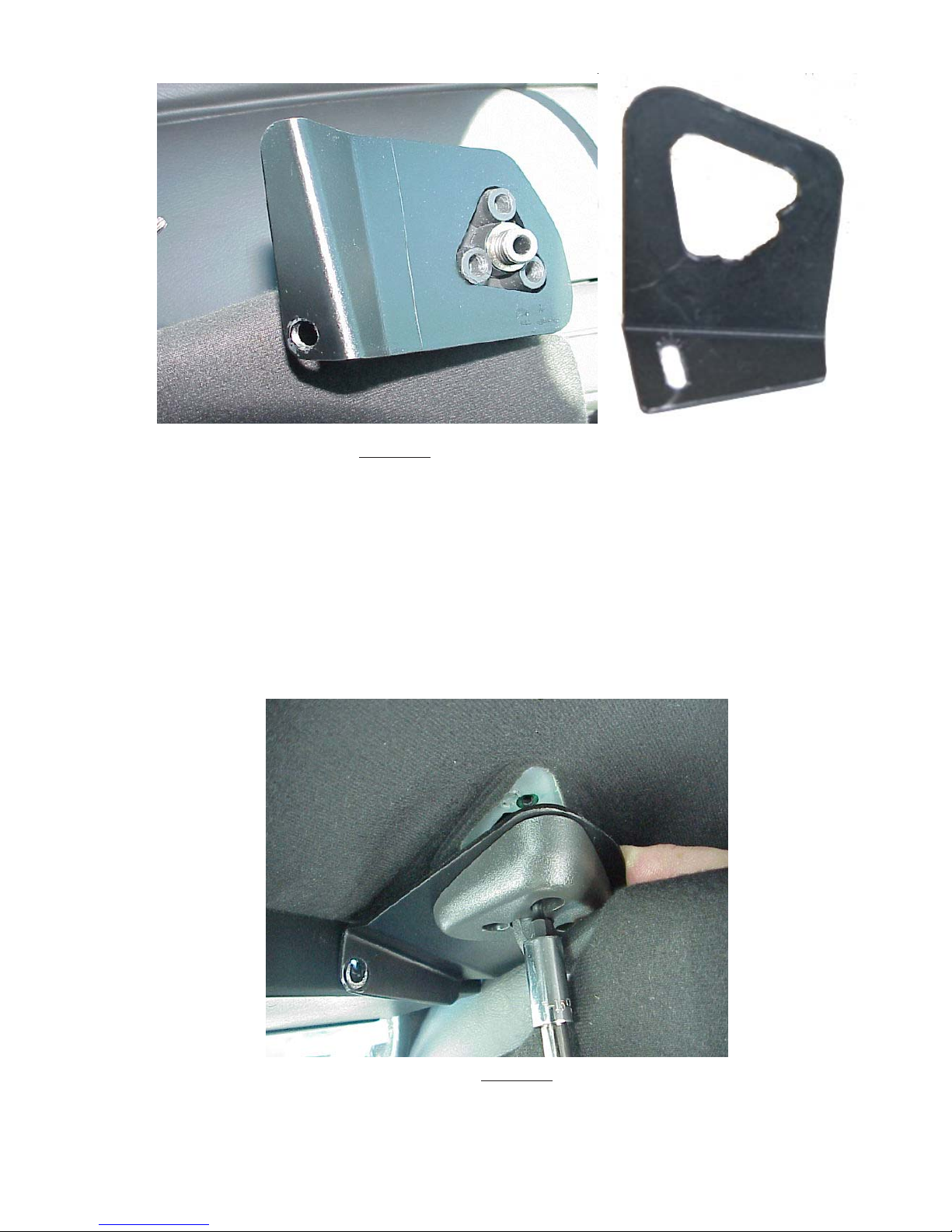
FIGURE 4
Outer mounting bracket modified
to fit all 2005 Crown Victorias
FIGURE 5
5
Page 20

FIGURE 6
FIGURE 7
6
Page 21
Mounting the SuperVisor™
Before mounting the SuperVisor, apply gasket stripping to the front edge of the lower chassis in order to
prevent scratching the windshield. See Figure 8. Once all four brackets and sun visors are attached, the
two SuperVisors are now ready to be installed. Position the Driver Side SuperVisor to center between the
Driver Side Brackets and align with the mounting holes as shown in Figure 9. Repeat for Passenger Side.
FIGURE 8
FIGURE 9
7
Page 22

Mounting the SuperVisor™ (continued)
The inside bracket should line up with the holes in the SuperVisor's lower chassis. Using the supplied 1/4"20 bolts and internal tooth lock washers, loosely install them as shown in Figure 10.
FIGURE 10
Next, if necessary, slightly loosen the three pivot arm bracket and sun visor retaining clip torx screws in
order to align the pivot arm bracket's hole with the mating chassis hole on the end of the SuperVisor.
Finally, thread the supplied bolts and the internal tooth lock washers through the pivot arm bracket's hole
into the hole on the end of the chassis, shown in Figure 11. Tighten all pivot arm and sun visor retaining
clip torx screws.Using a tape measure and a level, center the SuperVisor from side to side and locate a
position on the headliner where the SuperVisor is level. Finally, tighten both bolts securely. Do not
overtighten. Repeat these steps for the passenger side.
Caution: The bracket fasteners make excellent hard mounting points for
radar guns and video cameras etc. Drilling into the housing of the light
bar could damage wiring or other internal components.
FIGURE 11
8
Page 23

.
Wiring Diagram
9
Page 24

Wiring Instructions
Larger wires and tight connections will provide longer service life for components. For
high current wires it is highly recommended that terminal blocks or soldered connections
!
WARNING!
be used with shrink tubing to protect the connections. Do not use insulation displacement connectors (e.g. 3M® Scotchlock type connectors). Route wiring using grommets
and sealant when passing through compartment walls. Minimize the number of splices
to reduce voltage drop. High ambient temperatures (e.g. underhood) will significantly
reduce the current carrying capacity of wires, fuses, and circuit breakers. Use "SXL"
type wire in engine compartment. All wiring should conform to the minimum wire size
and other recommendations of the manufacturer and be protected from moving parts
and hot surfaces. Looms, grommets, cable ties, and similar installation hardware
should be used to anchor and protect all wiring. Fuses or circuit breakers should be
located as close to the power takeoff points as possible and properly sized to protect the
wiring and devices. Particular attention should be paid to the location and method of
making electrical connections and splices to protect these points from corrosion and loss
of conductivity. Ground terminations should only be made to substantial chassis
components, preferably directly to the vehicle battery. The user should install a fuse
sized to approximately 125% of the maximum Amp capacity in the supply line to protect
against short circuits. For example, a 30 Amp fuse should carry a maximum of 24
Amps. DO NOT USE 1/4" DIAMETER GLASS FUSES AS THEY ARE NOT SUITABLE
FOR CONTINUOUS DUTY IN SIZES ABOVE 15 AMPS. Circuit breakers are very
sensitive to high temperatures and will "false trip" when mounted in hot environments or
operated close to their capacity.
Route the wiring cable into the passenger compartment as shown in Figure 12. It is advisable to leave
an extra loop of cable when installing the light bar to allow for future changes or reinstallations. Connect
the black lead to a solid frame ground (earth), preferably, the (-) or ground (earth) side of the battery,
and the remaining power wires to the +12V terminal of the battery, power switches, siren or RLS
controller. Each light head is wired independently to allow complete flexibility of control.
FIGURE 12
10
Page 25

LED Fusing Considerations
Although the average current draw per module is very low, due to the type of circuit used to power each
module, the instantaneous peak current to a module can be significantly higher during low voltage
conditions. To avoid prematurely blowing ATO style fuses or tripping breakers it is recommended the
following rule-of-thumb be used to size fuses or breakers. This is especially important in light bars with
many LED modules running off a single fused source,
Minimum fuse size calculation:
For LED 12 volt electrical current only
1.5 x (number of modules being fused)
Example: 2 intersection modules and 6 directional modules.
Minimum fuse requirement for single fuse - 1.5 (8) = 12 A
Total 12 volt electrical current
12A (for LED's) = 12 A
Product Features
LED lighthead options: Red, Blue, Amber; Directional or Spreading; Flashing or Steady Burn Control
Size: 45.50" long x 2.00" tall x 7.25" deep
Weight: 7.5 lb
WARNING!
This Product contains high intensity LED devices. To prevent eye damage,
!
DO NOT stare into light beam at close range.
WARNING!
Lamps are extremely hot! Allow to cool completely before attempting to
remove. Gloves and eye protection should be worn when handling halogen
lamps as they are pressurized and accidental breakage can result in flying
glass.
11
Page 26

LED Light Head Flash Pattern
Place jumpers as shown to select flash pattern:
See Figure 14, for jumper installation.
Jumper Position Flash Pattern Description
J1 J2
Bottom (on) Bottom (0n) Steady-Burn Steady-burn
Bottom (on) Top (off) Single Flash Single Flashes @ 75 fpm min
Top (off) Bottom (on) Quad Flash Four Pulses per flash @ 70 fpm min
Top (off) Top (off) Cycle-Flash Cycles through various patterns @ 70 fpm minimum
Jumper Installation
FIGURE 14
Troubleshooting
All SuperVisors are thoroughly tested prior to shipment. However, should you encounter a problem during
installation or during the life of the product, follow the guide below for information on repair and troubleshooting. Additional information may be obtained from the factory technical help line at 314-426-2700 ext. 2132.
Follow the guide below for information on repair and troubleshooting.
TROUBLESHOOTING GUIDE
Note: LED modules must be replaced as a module. There are no user serviceable parts.
PROBLEM
LED module not
operating when
powered.
QUESTIONS POSSIBLE CAUSE
N/A
a. Bad power/ground
connection.
b. Defective module.
SOLUTION
a. Fix connection.
b. Replace module
12
Page 27

Parts List
Reference Number Part Description Part Number
1 Opti-X Module T05612
2 *LED Module *Contact Code 3 for P/N
3 Chassis- Driver Side T15859
4 Chassis - Passenger Side T15860
5 Outer Panel - Driver Side T15861
6 Outer Panel - Passenger Side T15862
Not Shown Inner Mtg. Brkt. Crown Vic T15917
Not Shown Outer Mtg. Brkt. Crown Vic Pass T15919
Not Shown Outer Mtg. Brkt. Crown Vic Dr. T15918
13
Page 28

WARRANTY
Code 3, Inc. emergency devices are tested and found to be operational at the time of
manufacture. Provided they are installed and operated in accordance with manufacturer's
recommendations, Code 3, Inc. guarantees all parts and components except the lamps to a period
of 1 year, LED Lighthead modules to a period of 5 years (unless otherwise expressed) from the
date of purchase or delivery, whichever is later. Units demonstrated to be defective within the
warranty period will be repaired or replaced at the factory service center at no cost.
Use of lamp or other electrical load of a wattage higher than installed or recommended by
the factory, or use of inappropriate or inadequate wiring or circuit protection causes this warranty
to become void. Failure or destruction of the product resulting from abuse or unusual use and/
or accidents is not covered by this warranty. Code 3, Inc. shall in no way be liable for other
damages including consequential, indirect or special damages whether loss is due to negligence
or breach of warranty.
CODE 3, INC. MAKES NO OTHER EXPRESS OR IMPLIED WARRANTY INCLUDING,
WITHOUT LIMITATION, WARRANTIES OF FITNESS OR MERCHANTABILITY, WITH
RESPECT TO THIS PRODUCT.
PRODUCT RETURNS
If a product must be returned for repair or replacement*, please contact our factory to
obtain a Return Goods Authorization Number (RGA number) before you ship the product to
Code 3, Inc. Write the RGA number clearly on the package near the mailing label. Be sure you
use sufficient packing materials to avoid damage to the product being returned while in transit.
*Code 3, Inc. reserves the right to repair or replace at its discretion. Code 3, Inc. assumes no responsibility or liability for expenses incurred for
the removal and /or reinstallation of products requiring service and/or repair.; nor for the packaging, handling, and shipping: nor for the handling of
products returned to sender after the service has been rendered.
NEED HELP? Call our Technical Assistance Hotline - (314) 996-2800
St. Louis, Missouri 63114-2029—USA
Ph. (314) 426-2700 Fax (314) 426-1337
10986 N. Warson Road
www.code3pse.com
Code 3, Inc.
Code 3 is a registered trademark of Code 3, Inc. a subsidiary of Public Safety Equipment, Inc.
16
Revision 2 12/2005 - Instruction Book Part No. T15863
©2005 Public Safety Equipment, Inc. Printed in USA
Page 29

INSTALLATION
& OPERATION
MANUAL
SUPERVISOR™
SuperVisor
CONTENTS:
Introduction. ........................................................... 2
Unpacking & Pre-Installation. ................................ 3
Installation & Mounting ....................................... 3-8
Wiring Diagram & Instructions .......................... 9-10
Fusing and MR8 Lamp Installation ...................... 11
LED Flash pattern selection & Troubleshooting .. 12
Exploded View & Parts List ................................. 13
Warranty .............................................................. 16
For future reference record your product's serial no. here
__________________________________________
IMPORTANT:
Read all instructions and warnings before installing and using.
INSTALLER:
This manual must be delivered to the end user of this equipment.
™
Interior Lighting System
Ford Explorer
Page 30

Introduction
The SuperVisor™ is an interior lighting system that fits in the visor area near the top of the windshield. It
delivers an amazing warning signal, including MR8 powered takedown lights.
The SuperVisor is designed on a modular basis, which means that the light bar can be customized to meet
most any requirements. The SuperVisor has room for up to eight LED lightheads plus two MR8 takedowns.
Each lighthead is individually wired for any flash pattern or combination of flash patterns required.
The use of this or any warning device does not ensure that all drivers can or will observe
or react to an emergency warning signal. Never take the right-of-way for granted. It is
your responsibility to be sure you can proceed safely before entering an intersection,
driving against traffic, responding at a high rate of speed, or walking on or around traffic
lanes.
The effectiveness of this warning device is highly dependent upon correct mounting and
wiring. Read and follow the manufacturer’s instructions before installing or using this
device. The vehicle operator should insure daily that all features of the device operate
correctly. In use, the vehicle operator should insure the projection of the warning signal
is not blocked by vehicle components (i.e.: open trunks or compartment doors), people,
!
WARNING!
vehicles, or other obstructions.
This equipment is intended for use by authorized personnel only. It is the user’s responsibility to understand and obey all laws regarding emergency warning devices. The user
should check all applicable city, state and federal laws and regulations.
Code 3, Inc., assumes no liability for any loss resulting from the use of this warning
device.
Proper installation is vital to the performance of this warning device and the safe operation of the emergency vehicle. It is important to recognize that the operator of the
emergency vehicle is under psychological and physiological stress caused by the emergency situation. The warning device should be installed in such a manner as to: A) Not
reduce the output performance of the system, B) Place the controls within convenient
reach of the operator so that he can operate the system without losing eye contact with
the roadway.
Emergency warning devices often require high electrical voltages and/or currents.
Properly protect and use caution around live electrical connections. Grounding or
shorting of electrical connections can cause high current arcing, which can cause personal injury and/or severe vehicle damage, including fire.
Any electronic device may create or be affected by electronmagnetic interference. After
installation of any electronic device operate all equipment simultaneously to insure that
operation is free of interference. Never power emergency warning equipment from the
same circuit or share the same grounding circuit with radio communication equipment.
PROPER INSTALLATION COMBINED WITH OPERATOR TRAINING IN THE PROPER
USE OF EMERGENCY WARNING DEVICES IS ESSENTIAL TO INSURE THE SAFETY
OF EMERGENCY PERSONNEL AND THE PUBLIC.
All devices should be mounted in accordance with the manufacturer's instructions and
securely fastened to vehicle elements of sufficient strength to withstand the forces
applied to the device. Driver and/or passenger airbags (SRS) will affect the way equipment should be mounted. This device should be mounted by permanent installation and
within the zones specified by the vehicle manufacturer, if any. Any device mounted in the
deployment area of an air bag will damage or reduce the effectiveness of the air bag and
may damage or dislodge the device. Installer must be sure that this device, its mounting
hardware and electircal supply wiring does not interfere with the air bag or the SRS
wiring or sensors. Mounting the unit inside the vehicle by a method other than permanent
installation is not recommended as unit may become dislodged during swerving, sudden
braking or collision. Failure to follow instructions can result in personal injury.
2
Page 31

Unpacking & Pre-installation
Carefully remove the SuperVisor™ and place it on a flat surface, taking care not to scratch the lenses or
damage the cables coming out of the sides. Examine the unit for transit damage, broken lamps, etc. Report
any damage to the carrier and keep the shipping carton.
Standard light bars are built to operate on 12 volt D.C. negative ground (earth) vehicles. If you have an
electrical system other than 12 volt D.C. negative ground (earth), and have not ordered a specially wired light
bar, contact the factory for instructions.
Test the unit before installation. To test, touch the black wire to the ground (earth) and the other wires to +12
volts D.C., in accordance with the instructions attached to the cable (an automotive battery is preferable for
this test). Some units may be factory wired for control by a LED flasher in which case the cable's wire tag
should be consulted. A battery charger may be used, but please note that some electronic options (flashers,
stingrays, etc.) may not operate normally when powered by a battery charger. If problems occur at this point,
contact the factory.
Utilizing non-factory supplied screws and/or mounting brackets and/or the
WARNING!
Mounting Hardware - All mounting hardware is packed in a small box inside the main carton. There are four
brackets used to mount the visor bars to the vehicle. These are discussed in detail later.
!
improper number of screws may result in loss of warranty coverage on the
equipment.
Removing Sun Visors
Begin the installation by removing the Explorer's driver and passenger sun visors. There are two screws
that hold the pivotal arm of the sun visor to the headliner. Unclip the screw cover as shown in Figure 1 and
remove each screw using a phillips screwdriver. If the sun visor has a lighted mirror, gently allow the sun
visor to hang by the attached wire, taking care not to damage this wire.
FIGURE 1
3
Page 32

Attach brackets to sun visor retaining clips
In order to remove the sun visor retaining clip, unscrew the phillips screw holding it in place. Place the
passenger side inner bracket on the passenger side retaining clip as shown in Figure 2, noting the
difference between passenger and driver side brackets. Attach the inner bracket and retaining clip to the
headliner as illustrated in Figure 3. Do not tighten these screws at this time.
FIGURE 2
FIGURE 3
4
Page 33

Attaching the pivot arm brackets
Attach the passenger side outer brackets that are supplied noting the difference between passenger and
driver side brackets. Slide the bracket in place using the notch in the bracket to clear the attached wire as
show in Figure 4. Position the bracket on the passenger sun visor's pivot arm and verify the orientation of
the bracket as shown in Figure 5. Attach the phillips screws as shown in Figure 6. Repeat this operation
for the driver side sun visor and outer bracket.
FIGURE 4
FIGURE 5
5
Page 34

FIGURE 6
FIGURE 7 (Passenger Side)
6
Page 35

Mounting the SuperVisor™
Before mounting the SuperVisor, apply gasket stripping to the front edges of the lower chassis in order to
prevent scratching the windshield. See Figure 8. Once all four brackets and sun visors are attached, the
SuperVisor is now ready to be installed. Position the passenger side SuperVisor in the center of the
passenger side brackets as shown in Figure 9.
FIGURE 8
FIGURE 9
7
Page 36

Mounting the SuperVisor™ (continued)
The two center brackets should line up with the holes in the SuperVisor's lower chassis. Using the supplied
1/4"-20 bolts and internal tooth lock washers, loosely install the retainer clip bracket as shown in Figure
10.
FIGURE 10
Next, if necessary, slightly loosen the pivot arm bracket and sun visor retaining clip screws in order to align
the pivot arm bracket's hole with the mating chassis hole on the end of the SuperVisor. Finally, thread the
supplied bolts and the internal tooth lock washers through the pivot arm bracket's hole into the hole on the
end of the chassis, shown in Figure 11. Tighten all pivot arm and sun visor retaining clip screws.Using a
tape measure, center the SuperVisor from side to side. Make sure the superVisor is pushed snug to the
headliner, as shown in Figure 12. Finally, tighten both bolts securely. Do not overtighten. Repeat the
mounting procedure for the driver side SuperVisor as show in figure 12A.
FIGURE 12
FIGURE 11
FIGURE 12A
Caution: The bracket fasteners make excellent hard mounting points for
radar guns and video cameras etc. Drilling into the housing of the light
bar could damage wiring or other internal components.
8
Page 37

Wiring Diagram
9
Page 38

Wiring Instructions
Larger wires and tight connections will provide longer service life for components. For
high current wires it is highly recommended that terminal blocks or soldered connections
!
WARNING!
be used with shrink tubing to protect the connections. Do not use insulation displacement connectors (e.g. 3M® Scotchlock type connectors). Route wiring using grommets
and sealant when passing through compartment walls. Minimize the number of splices
to reduce voltage drop. High ambient temperatures (e.g. underhood) will significantly
reduce the current carrying capacity of wires, fuses, and circuit breakers. Use "SXL"
type wire in engine compartment. All wiring should conform to the minimum wire size
and other recommendations of the manufacturer and be protected from moving parts
and hot surfaces. Looms, grommets, cable ties, and similar installation hardware
should be used to anchor and protect all wiring. Fuses or circuit breakers should be
located as close to the power takeoff points as possible and properly sized to protect the
wiring and devices. Particular attention should be paid to the location and method of
making electrical connections and splices to protect these points from corrosion and loss
of conductivity. Ground terminations should only be made to substantial chassis
components, preferably directly to the vehicle battery. The user should install a fuse
sized to approximately 125% of the maximum Amp capacity in the supply line to protect
against short circuits. For example, a 30 Amp fuse should carry a maximum of 24
Amps. DO NOT USE 1/4" DIAMETER GLASS FUSES AS THEY ARE NOT SUITABLE
FOR CONTINUOUS DUTY IN SIZES ABOVE 15 AMPS. Circuit breakers are very
sensitive to high temperatures and will "false trip" when mounted in hot environments or
operated close to their capacity.
Route the wiring cables into the passenger compartment as shown in Figure 13. It is advisable to leave
an extra loop of cable when installing the light bar to allow for future changes or reinstallations. Connect
the black lead to a solid frame ground (earth), preferably, the (-) or ground (earth) side of the battery,
and the remaining power wires to the +12V terminal of the battery, power switches, siren or RLS
controller. The MR8 takedowns may be installed to a flasher. The fan should be wired to operate
continuously whenever the takedowns are in operation, either flashing or steady burn. Each light head is
wired independently to allow complete flexibility of control.
FIGURE 13
10
Page 39

LED Fusing Considerations
Although the average current draw per module is very low, due to the type of circuit used to power each
module, the instantaneous peak current to a module can be significantly higher during low voltage
conditions. To avoid prematurely blowing ATO style fuses or tripping breakers it is recommended the
following rule-of-thumb be used to size fuses or breakers. This is especially important in light bars with
many LED modules running off a single fused source,
Minimum fuse size calculation:
For LED 12 volt electrical current only
1.5 x (number of modules being fused)
Example: 2 intersection modules and 6 directional modules.
Minimum fuse requirement for single fuse - 1.5 (8) = 12 A
For MR8 takedown and fan 12 volt electrical current only
Total wattage (1 MR8's = 35W, fan = 5W) divided 12volts = Amperage
Example: 2 MR8's and 1 fan = (75W/12) = 6.25 A
Total 12 volt electrical current
12A (for LED's) + 6.25A (for MR8's and fan) = 18.25 A
Product Features
LED lighthead options: Red, Blue, Amber; Directional or Spreading; Flashing or Steady Burn Control
MR8 Specs: 35w Halogen with 13° spot
Size: 45.50" long x 2.813" tall x 7.625" deep
Weight: 7.5 lb
WARNING!
!
This Product contains high intensity LED devices. To prevent eye damage,
DO NOT stare into light beam at close range.
MR8 Takedown Light Assembly
Refer to Figure 14 for lamp replacement. Remove the lamp assembly from the product by disconnecting the
two electrical wires and removing the appropriate fastener. Remove the fastener clamping the lamp and then
remove the lamp from the mounting bracket. Disconnect the lamp from the ceramic connector and reinstall a
new lamp. The lamp lens should be cleaned to remove fingerprints then reinstall the lamp assembly in the
light bar and reconnect the electrical wires. Reassemble the components in reverse order.
FIGURE 14
!
WARNING!
Lamps are extremely hot! Allow to cool completely before attempting to
remove. Gloves and eye protection should be worn when handling halogen
lamps as they are pressurized and accidental breakage can result in flying
glass.
11
Page 40

LED Light Head Flash Pattern
Place jumpers as shown to select flash pattern:
See Figure 14, for jumper installation.
Jumper Position Flash Pattern Description
J1 J2
Bottom (on) Bottom (0n) Steady-Burn Steady-burn
Bottom (on) Top (off) Single Flash Single Flashes @ 75 fpm min
Top (off) Bottom (on) Quad Flash Four Pulses per flash @ 70 fpm min
Top (off) Top (off) Cycle-Flash Cycles through various patterns @ 70 fpm minimum
Jumper Installation
FIGURE 15
Troubleshooting
All SuperVisors are thoroughly tested prior to shipment. However, should you encounter a problem during
installation or during the life of the product, follow the guide below for information on repair and troubleshooting. Additional information may be obtained from the factory technical help line at 314-426-2700 ext. 2132.
Follow the guide below for information on repair and troubleshooting.
TROUBLESHOOTING GUIDE
Note: LED modules must be replaced as a module. There are no user serviceable parts.
PROBLEM
LED module not
operating when
powered.
QUESTIONS POSSIBLE CAUSE
N/A
a. Bad power/ground
connection.
b. Defective module.
SOLUTION
a. Fix connection.
b. Replace module
12
Page 41

Parts List
Reference Number Part Description Part Number
1 +12V Cooling Fan T05612
2 *LED Module *Contact Code 3,Inc for P/N
3 MR8 lamp T09600
4 *Opti-X Light Module *Contact Code 3,Inc for P/N
5 Passenger Side Chassis T15841
6 Driver Side Chassis T15842
7 Passenger Side Outer Panel T15843
8 Driver Side Outer Panel T15844
9 MR8 Light Mounting Bracket T09601
Not Shown Passenger Side Outer Mtg. Bracket T15845
Not Shown Driver Side Outer Mtg. Bracket T15846
Not Shown Passenger Side Inner Mtg. Bracket T15847
Not Shown Driver Side Inner Mtg. Bracket T15848
13
Page 42

WARRANTY
Code 3, Inc.'s emergency devices are tested and found to be operational at the time of
manufacture. Provided they are installed and operated in accordance with manufacturer's
recommendations, Code 3, Inc. guarantees all parts and components except the lamps to a period
of 1 year, LED Lighthead modules to a period of 5 years (unless otherwise expressed) from the
date of purchase or delivery, whichever is later. Units demonstrated to be defective within the
warranty period will be repaired or replaced at the factory service center at no cost.
Use of lamp or other electrical load of a wattage higher than installed or recommended by
the factory, or use of inappropriate or inadequate wiring or circuit protection causes this warranty
to become void. Failure or destruction of the product resulting from abuse or unusual use and/
or accidents is not covered by this warranty. Code 3, Inc. shall in no way be liable for other
damages including consequential, indirect or special damages whether loss is due to negligence
or breach of warranty.
CODE 3, INC. MAKES NO OTHER EXPRESS OR IMPLIED WARRANTY INCLUDING,
WITHOUT LIMITATION, WARRANTIES OF FITNESS OR MERCHANTABILITY, WITH
RESPECT TO THIS PRODUCT.
PRODUCT RETURNS
If a product must be returned for repair or replacement*, please contact our factory to
obtain a Return Goods Authorization Number (RGA number) before you ship the product to
Code 3, Inc. Write the RGA number clearly on the package near the mailing label. Be sure you
use sufficient packing materials to avoid damage to the product being returned while in transit.
*Code 3, Inc. reserves the right to repair or replace at its discretion. Code 3, Inc. assumes no responsibility or liability for expenses incurred for
the removal and /or reinstallation of products requiring service and/or repair.; nor for the packaging, handling, and shipping: nor for the handling of
products returned to sender after the service has been rendered.
NEED HELP? CALL OUR TECHNICAL ASSISTANCE HOTLINE - (314) 996-2800
St. Louis, Missouri 63114-2029—USA
10986 N. Warson Road
www.code3pse.com
Code 3, Inc.
SuperVisor is a trademark of Code 3, Inc.
Code 3 is a registered trademark of Code 3, Inc. a subsidiary of Public Safety Equipment, Inc.
Revision 1, 12/2005 - Instruction Book Part No. T15849
©2004-5 Code 3, Inc. Printed in USA
Page 43

INSTALLATION &
OPERATION
MANUAL
SUPERVISOR™
SuperVisor™
Interior Lighting System
CHEVROLET IMPALA
CONTENTS:
Introduction..........................................................................2
Unpacking & Pre-Installation ...............................................3
Installation & Mounting .....................................................3-7
Wiring Diagram & Instructions .......................................... 8-9
Fusing and MR8 Lamp Installation.................................... 10
LED Flash pattern selection & Troubleshooting............... 11
Exploded View & Parts List.............................................. 12
Warranty ............................................................................ 16
For future reference record your product's serial no. here __________________________________________
Read all instructions and warnings before installing and using.
INSTALLER:
This manual must be delivered to the end user of this equipment.IMPORTANT:
Page 44

Introduction
The SuperVisor™ is an interior lighting system that fits in the visor area near the top of the windshield. It delivers an amazing warning
signal, including MR8 powered takedown lights.
The SuperVisor is designed on a modular basis, which means that the light bar can be customized to meet most any requirements.
The SuperVisor has room for up to eight LED lightheads plus two MR8 takedowns. Each lighthead is individually wired for any flash
pattern or combination of flash patterns required.
The use of this or any warning device does not ensure that all drivers can or will observe or react to an
emergency warning signal. Never take the right-of-way for granted. It is your responsibility to be sure you can
proceed safely before entering an intersection, driving against traffic, responding at a high rate of speed, or
walking on or around traffic lanes.
The effectiveness of this warning device is highly dependent upon correct mounting and wiring. Read and
follow the manufacturer’s instructions before installing or using this device. The vehicle operator should insure
daily that all features of the device operate correctly. In use, the vehicle operator should insure the projection
of the warning signal is not blocked by vehicle components (i.e.: open trunks or compartment doors), people,
vehicles, or other obstructions.
This equipment is intended for use by authorized personnel only. It is the user’s responsibility to understand
and obey all laws regarding emergency warning devices. The user should check all applicable city, state and
!
WARNING!
federal laws and regulations.
Code 3, Inc., assumes no liability for any loss resulting from the use of this warning device.
Proper installation is vital to the performance of this warning device and the safe operation of the emergency
vehicle. It is important to recognize that the operator of the emergency vehicle is under psychological and
physiological stress caused by the emergency situation. The warning device should be installed in such a
manner as to: A) Not reduce the output performance of the system, B) Place the controls within convenient
reach of the operator so that he can operate the system without losing eye contact with the roadway.
Emergency warning devices often require high electrical voltages and/or currents. Properly protect and use
caution around live electrical connections. Grounding or shorting of electrical connections can cause high
current arcing, which can cause personal injury and/or severe vehicle damage, including fire.
Any electronic device may create or be affected by electronmagnetic interference. After installation of any
electronic device operate all equipment simultaneously to insure that operation is free of interference. Never
power emergency warning equipment from the same circuit or share the same grounding circuit with radio
communication equipment.
PROPER INSTALLATION COMBINED WITH OPERATOR TRAINING IN THE PROPER USE OF EMERGENCY WARNING DEVICES IS ESSENTIAL TO INSURE THE SAFETY OF EMERGENCY PERSONNEL
AND THE PUBLIC.
All devices should be mounted in accordance with the manufacturer's instructions and securely fastened to
vehicle elements of sufficient strength to withstand the forces applied to the device. Driver and/or passenger
airbags (SRS) will affect the way equipment should be mounted. This device should be mounted by permanent
installation and within the zones specified by the vehicle manufacturer, if any. Any device mounted in the
deployment area of an air bag will damage or reduce the effectiveness of the air bag and may damage or
dislodge the device. Installer must be sure that this device, its mounting hardware and electircal supply wiring
does not interfere with the air bag or the SRS wiring or sensors. Mounting the unit inside the vehicle by a
method other than permanent installation is not recommended as unit may become dislodged during swerving,
sudden braking or collision. Failure to follow instructions can result in personal injury.
2
Page 45

Unpacking & Pre-installation
Carefully remove the SuperVisor™ and place it on a flat surface, taking care not to scratch the lenses or damage the cable coming
out of the side. Examine the unit for transit damage, broken lamps, etc. Report any damage to the carrier and keep the shipping
carton.
Standard light bars are built to operate on 12 volt D.C. negative ground (earth) vehicles. If you have an electrical system other than
12 volt D.C. negative ground (earth), and have not ordered a specially wired light bar, contact the factory for instructions.
Test the unit before installation. To test, touch the black, (and if present grey, purple, and brown) wire(s) to the ground (earth) and the
other wires to +12 volts D.C., in accordance with the instructions attached to the cable (an automotive battery is preferable for this
test). A battery charger may be used, but please note that some electronic options (flashers, stingrays, etc.) may not operate
normally when powered by a battery charger. If problems occur at this point, contact the factory.
Installation & Mounting
WARNING!
Mounting Hardware - All mounting hardware is packed in a small box inside the main carton. There are four brackets used to mount the
visor bar to the vehicle. These are discussed in detail later.
!
Utilizing non-factory supplied screws and/or mounting brackets and/or the improper number
of screws may result in loss of warranty coverage on the equipment.
Removing Sun Visors
Begin the installation by removing the Chevrolet Impala's driver and passenger sun visors. Identify each visor with tape or other
marking to indicate the driver from the passenger side unit. They are not identical. There are three screws that hold the pivotal arm of
the sun visor to the headliner. Remove the two outer screws using a small torx screwdriver. Then unclip the sun visor and rotate it over
to expose the last screw as shown in Figure 1.
FIGURE 1
3
Page 46

Attach brackets to sun visor retaining clips
In order to remove the sun visor retaining clip, unscrew the one torx screw holding it in place. Place the inner bracket on the retaining
clip as shown in Figure 2. Attach the inner bracket and retaining clip to the headliner as illustrated in Figure 3. Do not completely tighten
the screw at this time.
FIGURE 2
FIGURE 3
4
Page 47

Attaching the pivot arm brackets
Attach the outer brackets that are supplied noting the difference between passenger and driver side brackets. Position the driver's side
bracket on the driver's side sun visor's pivot arm as shown in Figure 4. Attach the driver's side bracket to the headliner with the inner
torx screw as shown in figure 5. Next, move the sun visor over to gain access to install the other two torx screws. Do not tighten the
screws at this time. Repeat the same proceedure to attach the passenger's side outer bracket.
FIGURE 4
FIGURE 5
5
Page 48

Mounting the SuperVisor™
Before mounting the SuperVisor, apply gasket stripping to the front edge of the lower chassis in order to prevent scratching the
windshield. See Figure 6. Once all four brackets and sun visors are attached, the SuperVisor is now ready to be installed. Position the
SuperVisor in the center of the windshield as shown in Figure 7.
FIGURE 6
FIGURE 7
6
Page 49

Mounting the SuperVisor™ (continued)
The two center brackets should line up with the holes in the SuperVisor's lower chassis. Using the supplied 1/4"-20 bolts and the internal
tooth lock washers, loosely install them as shown in Figure 8.
FIGURE 8
Next, if necessary, slightly loosen the three pivot arm bracket retaining screws in order to align the pivot arm bracket's hole with the
mating chassis hole on the end of the SuperVisor. Finally, thread the supplied bolts and internal tooth lock washers through the pivot arm
bracket's hole into the hole on the end of the chassis, shown in Figure 9. Tighten all visor mounting torx screws.Next using a tape
measure and a level, center the SuperVisor from side to side and locate a position on the headliner where the SuperVisor is level.
Finally, tighten all four bolts securely. Do not overtighten.
Note:Figure 8 and 9 brackets are excellant hard mounting points for radar guns,
video cameras, or etc.
Caution:Drilling into the housing of the light bar could damage internal wiring,
circuitry, or other internal components.
FIGURE 9
7
Page 50

Wiring Diagram
8
Page 51

Wiring Instructions
Larger wires and tight connections will provide longer service life for components. For high current wires it is
!
WARNING!
highly recommended that terminal blocks or soldered connections be used with shrink tubing to protect the
connections. Do not use insulation displacement connectors (e.g. 3M® Scotchlock type connectors). Route
wiring using grommets and sealant when passing through compartment walls. Minimize the number of splices to
reduce voltage drop. High ambient temperatures (e.g. underhood) will significantly reduce the current carrying
capacity of wires, fuses, and circuit breakers. Use "SXL" type wire in engine compartment. All wiring should
conform to the minimum wire size and other recommendations of the manufacturer and be protected from moving
parts and hot surfaces. Looms, grommets, cable ties, and similar installation hardware should be used to
anchor and protect all wiring. Fuses or circuit breakers should be located as close to the power takeoff points as
possible and properly sized to protect the wiring and devices. Particular attention should be paid to the location
and method of making electrical connections and splices to protect these points from corrosion and loss of
conductivity. Ground terminations should only be made to substantial chassis components, preferably directly to
the vehicle battery. The user should install a fuse sized to approximately 125% of the maximum Amp capacity in
the supply line to protect against short circuits. For example, a 30 Amp fuse should carry a maximum of 24
Amps. DO NOT USE 1/4" DIAMETER GLASS FUSES AS THEY ARE NOT SUITABLE FOR CONTINUOUS
DUTY IN SIZES ABOVE 15 AMPS. Circuit breakers are very sensitive to high temperatures and will "false trip"
when mounted in hot environments or operated close to their capacity.
Route the wiring cable into the passenger compartment as shown in Figure 10. It is advisable to leave an extra loop of cable when
installing the light bar to allow for future changes or reinstallations. Connect the black lead to a solid frame ground (earth), preferably,
the (-) or ground (earth) side of the battery, and the remaining power wires to the +12V terminal of the battery, power switches, siren
or RLS controller. The MR8 takedowns may be installed to a flasher. The fan should be wired to operate continuously whenever the
takedowns are in operation, either flashing or steady burn. Each light head is wired independently to allow complete flexibility of
control.
FIGURE 10
9
Page 52

LED Fusing Considerations
Although the average current draw per module is very low, due to the type of circuit used to power each module, the instantaneous
peak current to a module can be significantly higher during low voltage conditions. To avoid prematurely blowing ATO style fuses or
tripping breakers it is recommended the following rule-of-thumb be used to size fuses or breakers. This is especially important in light
bars with many LED modules running off a single fused source,
Minimum fuse size calculation:
For LED 12 volt electrical current only
1.5 x (number of modules being fused)
Example: 2 intersection modules and 6 directional modules.
Minimum fuse requirement for single fuse - 1.5 (8) = 12 A
For MR8 takedown and fan 12 volt electrical current only
Total wattage (1 MR8's = 35W, fan = 5W) divided 12volts = Amperage
Example: 2 MR8's and 1 fan = (75W/12) = 6.25 A
Total 12 volt electrical current
12A (for LED's) + 6.25A (for MR8's and fan) = 18.25 A
Product Features
LED-X light head options: Red, Blue, Amber, White;
Directional or Wide Optics;
Flashing or Steady Burn Control
6 LED Optix light head options: Red, Blue, Amber, White;
Directional or Wide Optics;
Flashing or Steady Burn Control
3 LED Optix light head options: Red, Blue, Amber, White;
Directional, Wide or Hybrid Optics;
Flashing or Steady Burn Control
33 Optix light head options: Two 3-LED Heads with one 6-LED Optic
Red, Blue, Amber, White;
Directional , Wide or Hybrid Optics;
Flashing or Steady Burn Control
LC-LED light head options: Red, Blue, Amber;
Flashing or Steady Burn Control
MR8 Specs: 35w Halogen with 13° spot
Size: 45.50" long x 2.18" tall x 7.95" deep
Weight: 7.5 lb
WARNING!
!
This Product contains high intensity LED devices. To prevent eye damage, DO NOT stare into
light beam at close range.
MR8 Takedown Light Assembly
Refer to Figure 13 for lamp replacement. Remove the lamp assembly from the product by disconnecting the two electrical wires and
removing the appropriate fastener. Remove the fastener clamping the lamp and then remove the lamp from the mounting bracket.
Disconnect the lamp from the ceramic connector and reinstall a new lamp. The lamp lens should be cleaned to remove fingerprints then
reinstall the lamp assembly in the light bar and reconnect the electrical wires. Reassemble the components in reverse order.
FIGURE 13
!
WARNING!
Lamps are extremely hot! Allow to cool completely before attempting to remove. Gloves and eye
protection should be worn when handling halogen lamps as they are pressurized and accidental
breakage can result in flying glass.
10
Page 53

Directional module Flash Pattern - Table 2
Flash Pattern Description
Cycle Flash Cycles through various patterns @ 70 fpm
Steady-Burn Steady-Burn
Five Flash Five Pulses per flash @ 70 fpm
Quad Flash Four Pulses per flash @ 70 fpm
Triple Flash Three Pulses per flash @ 70 fpm
Double Flash Two Pulses per flash @ 70 fpm
Fast Double Flash Two Pulses per flash @ 85 fpm
NFPA Four Pulses, 70% Duty Cycle @ 75 fpm
Quad Pop Flash Four Pulses per flash ( 3 equal, 1 extended) @ 70 fpm
Triple Pop Flash Three Pulses per flash ( 2 equal, 1 extended) @ 70 fpm
Momentarily short and release
to change patterns
FIGURE 33
J1
PCB
Flash Pattern Header for OPTIX/LEDX
FIGURE 14
Troubleshooting
All SuperVisors are thoroughly tested prior to shipment. However, should you encounter a problem during installation or during the life of
the product, follow the guide below for information on repair and troubleshooting. Additional information may be obtained from the factory
technical help line at 314-996-2800.
Follow the guide below for information on repair and troubleshooting.
TROUBLESHOOTING GUIDE
Note: LED modules must be replaced as a module. There are no user serviceable parts.
PROBLEM
QUESTIONS
POSSIBLE CAUSE
SOLUTION
LED module not
operating when
powered.
N/A
a. Bad power/ground
connection.
b. Defective module.
11
a. Fix connection.
b. Replace module
Page 54

Parts List
Reference Number Part Description Part Number
1 +12V Cooling Fan T05612
2 *LEDX LED Module *Contact Code 3, Inc for P/N
3 MR8 lamp T09600
4 Chassis T09614
5 Outer Panel S51410
6 *Optix LED Module *Contact Code 3, Inc for P/N
Not Shown Inner Mtg. Brkt. Impala T09615
Not Shown Outer Mtg. Brkt. Impala Pass. T09617
Not Shown Outer Mtg. Brkt. Impala Dr. T09616
12
Page 55

WARRANTY
Code 3, Inc.'s emergency devices are tested and found to be operational at the time of manufacture. Provided they
are installed and operated in accordance with manufacturer's recommendations, Code 3, Inc. guarantees all parts and
components except the lamps to a period of 1 year, LED Lighthead modules to a period of 5 years (unless otherwise expressed)
from the date of purchase or delivery, whichever is later. Units demonstrated to be defective within the warranty period will
be repaired or replaced at the factory service center at no cost.
Use of lamp or other electrical load of a wattage higher than installed or recommended by the factory, or use of
inappropriate or inadequate wiring or circuit protection causes this warranty to become void. Failure or destruction of the
product resulting from abuse or unusual use and/or accidents is not covered by this warranty. Code 3, Inc. shall in no way
be liable for other damages including consequential, indirect or special damages whether loss is due to negligence or breach
of warranty.
CODE 3, INC. MAKES NO OTHER EXPRESS OR IMPLIED WARRANTY INCLUDING, WITHOUT
LIMITATION, WARRANTIES OF FITNESS OR MERCHANTABILITY, WITH RESPECT TO THIS PRODUCT.
PRODUCT RETURNS
If a product must be returned for repair or replacement*, please contact our factory to obtain a Return Goods
Authorization Number (RGA number) before you ship the product to Code 3, Inc. Write the RGA number clearly on the
package near the mailing label. Be sure you use sufficient packing materials to avoid damage to the product being returned
while in transit.
*Code 3, Inc. reserves the right to repair or replace at its discretion. Code 3, Inc. assumes no responsibility or liability for expenses incurred for the removal and /or
reinstallation of products requiring service and/or repair.; nor for the packaging, handling, and shipping: nor for the handling of products returned to sender after the service has
been rendered.
NEED HELP? Call our Technical Assistance HOTLINE - (314) 996-2800
St. Louis, Missouri 63114-2029—USA
Ph. (314) 426-2700 Fax (314) 426-1337
10986 N. Warson Road
www.code3pse.com
Code 3®, Inc.
Code 3 is a registered trademark of Code 3, Inc. a subsidiary of Public Safety Equipment, Inc.
Revision 1, 11/05 - Instruction Book Part No. T09626
©2004 Public Safety Equipment, Inc. Printed in USA
16
Page 56

INSTALLATION
& OPERATION
MANUAL
SUPERVISOR™
SuperVisor™
Interior Lighting System
CHEVROLET TAHOE and other identical
interior cab GM vehicles
CONTENTS:
Introduction..............................................................................................2
Unpacking & Pre-Installation....................................................................3
Installation & Mounting..........................................................................3-7
Wiring Diagram & Instructions...............................................................8-9
Fusing and MR8 Lamp Installation.........................................................10
LED Flash pattern selection ..................................................................11
Troubleshooting......................................................................................12
Exploded View & Parts List....................................................................13
Notes.................................................................................................14-15
Warranty.................................................................................................16
For future reference record your product's serial no. here __________________________________________
Read all instructions and warnings before installing and using.
INSTALLER:
This manual must be delivered to the end user of this equipment.IMPORTANT:
Page 57

Introduction
The SuperVisor™ is an interior lighting system that fits in the visor area near the top of the windshield. It delivers an amazing warning
signal, including MR8 powered takedown lights.
The SuperVisor is designed on a modular basis, which means that the light bar can be customized to meet most any requirement.
The SuperVisor has room for up to eight LED lightheads plus two MR8 takedowns. Each lighthead is individually wired for any flash
pattern or combination of flash patterns required.
The use of this or any warning device does not ensure that all drivers can or will observe or react to an
emergency warning signal. Never take the right-of-way for granted. It is your responsibility to be sure you can
proceed safely before entering an intersection, driving against traffic, responding at a high rate of speed, or
walking on or around traffic lanes.
The effectiveness of this warning device is highly dependent upon correct mounting and wiring. Read and
follow the manufacturer’s instructions before installing or using this device. The vehicle operator should insure
daily that all features of the device operate correctly. In use, the vehicle operator should insure the projection
of the warning signal is not blocked by vehicle components (i.e.: open trunks or compartment doors), people,
vehicles, or other obstructions.
This equipment is intended for use by authorized personnel only. It is the user’s responsibility to understand
and obey all laws regarding emergency warning devices. The user should check all applicable city, state and
!
WARNING!
federal laws and regulations.
Code 3, Inc., assumes no liability for any loss resulting from the use of this warning device.
Proper installation is vital to the performance of this warning device and the safe operation of the emergency
vehicle. It is important to recognize that the operator of the emergency vehicle is under psychological and
physiological stress caused by the emergency situation. The warning device should be installed in such a
manner as to: A) Not reduce the output performance of the system, B) Place the controls within convenient
reach of the operator so that he can operate the system without losing eye contact with the roadway.
Emergency warning devices often require high electrical voltages and/or currents. Properly protect and use
caution around live electrical connections. Grounding or shorting of electrical connections can cause high
current arcing, which can cause personal injury and/or severe vehicle damage, including fire.
Any electronic device may create or be affected by electronmagnetic interference. After installation of any
electronic device operate all equipment simultaneously to insure that operation is free of interference. Never
power emergency warning equipment from the same circuit or share the same grounding circuit with radio
communication equipment.
PROPER INSTALLATION COMBINED WITH OPERATOR TRAINING IN THE PROPER USE OF EMERGENCY WARNING DEVICES IS ESSENTIAL TO INSURE THE SAFETY OF EMERGENCY PERSONNEL
AND THE PUBLIC.
All devices should be mounted in accordance with the manufacturer's instructions and securely fastened to
vehicle elements of sufficient strength to withstand the forces applied to the device. Driver and/or passenger
airbags (SRS) will affect the way equipment should be mounted. This device should be mounted by permanent
installation and within the zones specified by the vehicle manufacturer, if any. Any device mounted in the
deployment area of an air bag will damage or reduce the effectiveness of the air bag and may damage or
dislodge the device. Installer must be sure that this device, its mounting hardware and electircal supply wiring
does not interfere with the air bag or the SRS wiring or sensors. Mounting the unit inside the vehicle by a
method other than permanent installation is not recommended as unit may become dislodged during swerving,
sudden braking or collision. Failure to follow instructions can result in personal injury.
2
Page 58

Unpacking & Pre-installation
Carefully remove the SuperVisor™ and place it on a flat surface, taking care not to scratch the lenses or damage the cable coming out of the
side. Examine the unit for transit damage, broken lamps, etc. Report any damage to the carrier and keep the shipping carton.
Standard light bars are built to operate on 12 volt D.C. negative ground (earth) vehicles. If you have an electrical system other than 12
volt D.C. negative ground (earth), and have not ordered a specially wired light bar, contact the factory for instructions.
Test the unit before installation. To test, touch the black, (and if present grey, purple, and brown) wire(s) to the ground (earth) and the
other wires to +12 volts D.C., in accordance with the instructions attached to the cable (an automotive battery is preferable for this test). A
battery charger may be used, but please note that some electronic options (flashers, stingrays, etc.) may not operate normally when
powered by a battery charger. If problems occur at this point, contact the factory.
Installation & Mounting
WARNING!
Mounting Hardware - All mounting hardware is packed in a small box inside the main carton. There are four brackets used to mount
the visor bar to the vehicle. These are discussed in detail later.
!
Utilizing non-factory supplied screws and/or mounting brackets and/or the improper number
of screws may result in loss of warranty coverage on the equipment.
Removing Sun Visors
Begin the installation by removing the Chevrolet Tahoe's driver and passenger sun visors. There are three screws that hold the pivotal
arm of the sun visor to the headliner. Remove the two outer screws using a small torx screwdriver. Note: Reverse thread the screws
until they just release the visor pivot arm from the headliner, this keeps the screws attached to the visor pivot arm bracket so
that they are not easily lost. Unclip the sun visor and rotate it over to expose the last screw (as shown in Figure 1). It is not necessary
to unplug the visor vanity light wires (see figure 2). If the visor vanity light wires are unplugged identify each visor with tape or other
marking to indicate the driver from the passenger side unit (they are not identical).
FIGURE 1 FIGURE 2
3
Page 59

Attach brackets to sun visor retaining clips
In order to remove the sun visor retaining clip, unscrew the single torx screw holding it in place (see figure 3). Place the inner
bracket on the retaining clip (as shown in Figure 4). Attach the inner bracket and retaining clip to the headliner (as illustrated in
Figure 5). Do not completely tighten the screw at this time.
FIGURE 4
FIGURE 3
FIGURE 5
4
Page 60

Attaching the pivot arm brackets
Attach the outer brackets that are supplied noting the difference between passenger and driver side brackets. Position the driver's
side bracket on the driver's side sun visor's pivot arm (as shown in Figure 6). Check that the bracket fits flat against the plastic sun
visor's pivot arm bracket. If the outer bracket does not fit flat it may be necessary to trim some material from the wire staking area
which holds the visor vanity light wire in position (see figure 7). Attach the driver's side bracket to the headliner with the inner torx
screw (as shown in figure 8). Next, move the sun visor over to gain access to install the other two torx screws. Do not tighten the
screws at this time. Repeat the same proceedure to attach the passenger's side outer bracket.
FIGURE 6
------Wire staking area
----------------------------------------------
FIGURE 7
FIGURE 8
5
Page 61

Mounting the SuperVisor™
Before mounting the SuperVisor, apply gasket stripping to the front edge of the lower chassis in order to prevent scratching the windshield (see
Figure 9). Once all four brackets and sun visors are attached, the SuperVisor is now ready to be installed. Fold both sun visors in the up position
(see Figure 10). Fold the rear view mirror down as far as it will go to get it out of the way for the SuperVisor. Position the SuperVisor by pointing the
center front portion of the lower chassis up above the rear view mirror and raise the back of the lower chassis into a level position. Position the
SuperVisor in the center of the windshield (as shown in Figure 11). Note:it may be necessary to gently pull back on the mounting brackets to
slip the SuperVisor's lower chassis behind the mounting brackets.
FIGURE 9
FIGURE 10 FIGURE 11
6
Page 62

Mounting the SuperVisor™ (continued)
The two center brackets should line up with the holes in the SuperVisor's lower chassis. Using the supplied 1/4"-20 bolts and the
internal tooth lock washers, loosely install them (as shown in Figure 12).
FIGURE 12
Next, if necessary, slightly loosen the three pivot arm bracket retaining screws in order to align the pivot arm bracket's hole with the
mating chassis hole on the end of the SuperVisor. Finally, thread the supplied 1/4"-20 bolts and internal tooth lock washers through
the pivot arm bracket's hole into the hole on the end of the chassis (as shown in Figure 13). Tighten all visor mounting torx screws.
Next, using a tape measure and a level, center the SuperVisor from side to side and locate a position on the headliner where the
SuperVisor is level. Finally, tighten all four bolts securely. Do not overtighten.
Note: Figure 12 and 13 brackets are excellant hard mounting points for radar guns,
video cameras, or etc.
Caution: Drilling into the housing of the light bar could damage internal wiring, circuitry,
or other internal components.
FIGURE 13
7
Page 63

Wiring Diagram
8
Page 64

Wiring Instructions
Larger wires and tight connections will provide longer service life for components. For high current wires it
is highly recommended that terminal blocks or soldered connections be used with shrink tubing to protect
!
WARNING!
the connections. Do not use insulation displacement connectors (e.g. 3M® Scotchlock type connectors).
Route wiring using grommets and sealant when passing through compartment walls. Minimize the number
of splices to reduce voltage drop. High ambient temperatures (e.g. underhood) will significantly reduce the
current carrying capacity of wires, fuses, and circuit breakers. Use "SXL" type wire in engine compartment.
All wiring should conform to the minimum wire size and other recommendations of the manufacturer and be
protected from moving parts and hot surfaces. Looms, grommets, cable ties, and similar installation
hardware should be used to anchor and protect all wiring. Fuses or circuit breakers should be located as
close to the power takeoff points as possible and properly sized to protect the wiring and devices. Particular
attention should be paid to the location and method of making electrical connections and splices to protect
these points from corrosion and loss of conductivity. Ground terminations should only be made to
substantial chassis components, preferably directly to the vehicle battery. The user should install a fuse
sized to approximately 125% of the maximum Amp capacity in the supply line to protect against short
circuits. For example, a 30 Amp fuse should carry a maximum of 24 Amps. DO NOT USE 1/4" DIAMETER
GLASS FUSES AS THEY ARE NOT SUITABLE FOR CONTINUOUS DUTY IN SIZES ABOVE 15 AMPS.
Circuit breakers are very sensitive to high temperatures and will "false trip" when mounted in hot environments or operated close to their capacity.
Route the wiring cable into the passenger compartment (as shown in Figure 14). It is advisable to leave an extra loop of cable
when installing the light bar to allow for future changes or reinstallations. Connect the black lead to a solid frame ground
(earth), preferably, the (-) or ground (earth) side of the battery, and the remaining power wires to the +12V terminal of the
battery, power switches, siren or RLS controller. The MR8 takedowns may be installed to a flasher. The fan should be wired to
operate continuously whenever the takedowns are in operation, either flashing or steady burn. Each light head is wired
independently to allow complete flexibility of control.
FIGURE 14
9
Page 65

LED Fusing Considerations
Although the average current draw per module is very low, due to the type of circuit used to power each module, the
instantaneous peak current to a module can be significantly higher during low voltage conditions. To avoid prematurely blowing
ATO style fuses or tripping breakers it is recommended the following rule-of-thumb be used to size fuses or breakers. This is
especially important in light bars with many LED modules running off a single fused source,
Minimum fuse size calculation:
For LED 12 volt electrical current only
1.5 x (number of modules being fused)
Example: 2 intersection modules and 6 directional modules.
Minimum fuse requirement for single fuse - 1.5 (8) = 12 A
For MR8 takedown and fan 12 volt electrical current only
Total wattage (1 MR8's = 35W, fan = 5W) divided 12volts = Amperage
Example:2 MR8's and 1 fan = (75W/12) = 6.25 A
Total 12 volt electrical current
12A (for LED's) + 6.25A (for MR8's and fan) = 18.25 A
WARNING!
!
This Product contains high intensity LED devices. To prevent eye damage, DO NOT stare
into light beam at close range.
MR8 Alley Light Assembly
Refer to Figure 15 for lamp replacement. Remove the lamp assembly from the product by disconnecting the two electrical wires and
removing the appropriate fastener. Remove the fastener clamping the lamp and then remove the lamp from the mounting bracket.
Disconnect the lamp from the ceramic connector and reinstall a new lamp. The lamp lens should be cleaned to remove fingerprints
then reinstall the lamp assembly in the light bar and reconnect the electrical wires. Reassemble the components in reverse order.
Lamps are extremely hot! Allow to cool completely before attempting to remove. Gloves and
!
eye protection should be worn when handling halogen lamps as they are pressurized and
accidental breakage can result in flying glass.
WARNING!
FIGURE 15
10
Page 66

Directional module Flash Pattern - Table 2
Flash Pattern Description
Cycle Flash Cycles through various patterns @ 70 fpm
Steady-Burn Steady-Burn
Five Flash Five Pulses per flash @ 70 fpm
Quad Flash Four Pulses per flash @ 70 fpm
Triple Flash Three Pulses per flash @ 70 fpm
Double Flash Two Pulses per flash @ 70 fpm
Fast Double Flash Two Pulses per flash @ 85 fpm
NFPA Four Pulses, 70% Duty Cycle @ 75 fpm
Quad Pop Flash Four Pulses per flash ( 3 equal, 1 extended) @ 70 fpm
Triple Pop Flash Three Pulses per flash ( 2 equal, 1 extended) @ 70 fpm
Momentarily short and release
to change patterns
FIGURE 33
J1
PCB
Flash Pattern Header for OPTIX/LEDX
LC-LED Light Head Flash Pattern Selection
The LC-LED light heads are equipped with one steady burn and three flashing patterns. To select a different flash pattern, apply +12
or +24 VDC to the red wire and connect the black wire to the power supply ground. The unit will flash in whatever pattern was last set.
Change the pattern by momentarily touching the white wire to the power supply ground. The flash pattern will change to the next
pattern according to the following list:
-Steady Burn
-75 FPM Single
-75 FPM Quad
-Cycle Flash
Continue to cycle through the various patterns until the desired pattern is selected. The unit will retain this pattern even when power
is removed.
inadvertent changes to the flash pattern. This can be accomplished by sealing or capping the end of the wire.
Note: The white flash pattern selection wire must be protected from contact with the system ground to prevent
For units that are flashed with an external control system such as a multiplexer or a flasher unit, the heads should be set to steady
burn. Note: Regardless of the location in the program in the flash pattern list, the unit can be forced to steady burn by permanently
electrically tying the white wire to the black wire.
It is recommended that all heads be set to the desired pattern at a workbench prior to installation.
11
Page 67

Troubleshooting
All SuperVisors are thoroughly tested prior to shipment. However, should you encounter a problem during installation or during the life of
the product, follow the guide below for information on repair and troubleshooting. Additional information may be obtained from the factory
technical help line at 314-996-2800.
Follow the guide below for information on repair and troubleshooting.
TROUBLESHOOTING GUIDE
Note: LED modules must be replaced as a module. There are no user serviceable parts.
PROBLEM
LED module not
operating when
powered.
QUESTIONS
N/A
POSSIBLE CAUSE
a. Bad power/ground
connection.
b. Defective module.
Product Features
LED-X light head options: Red, Blue, Amber, White;
Directional or Wide Optics;
Flashing or Steady Burn Control
6 LED Optix light head options: Red, Blue, Amber, White;
Directional or Wide Optics;
Flashing or Steady Burn Control
3 LED Optix light head options: Red, Blue, Amber, White;
Directional, Wide or Hybrid Optics;
Flashing or Steady Burn Control
SOLUTION
a. Fix connection.
b. Replace module
33 Optix light head options: Two 3-LED Heads with one 6-LED Optic
LC-LED light head options: Red, Blue, Amber;
MR8 Specs: 35w Halogen with 13° spot
Size: 45.50" long x 2.00" tall x 7.25" deep
Weight: 7.5 lb
Red, Blue, Amber, White;
Directional , Wide or Hybrid Optics;
Flashing or Steady Burn Control
Flashing or Steady Burn Control
12
Page 68

Parts List
Reference Number Part Description Part Number
1 +12V Cooling Fan T05612
2 *LED Module *Contact Code 3, Inc for P/N
3 MR8 lamp, 13 degree spread T09600
4 Chassis T09630
Chassis LC-LED T09634
5 Outer Panel T09629
Not Shown Inner Mtg. Brkt. Tahoe T09631
Not Shown Outer Mtg. Brkt. Tahoe Pass. T09633
Not Shown Outer Mtg. Brkt. Tahoe Dr. T09632
13
Page 69

WARRANTY
Code 3, Inc.'s emergency devices are tested and found to be operational at the time of manufacture. Provided they
are installed and operated in accordance with manufacturer's recommendations, Code 3, Inc. guarantees all parts and
components except the lamps to a period of 1 year, LED Lighthead modules to a period of 5 years (unless otherwise expressed)
from the date of purchase or delivery, whichever is later. Units demonstrated to be defective within the warranty period will
be repaired or replaced at the factory service center at no cost.
Use of lamp or other electrical load of a wattage higher than installed or recommended by the factory, or use of
inappropriate or inadequate wiring or circuit protection causes this warranty to become void. Failure or destruction of the
product resulting from abuse or unusual use and/or accidents is not covered by this warranty. Code 3, Inc. shall in no way
be liable for other damages including consequential, indirect or special damages whether loss is due to negligence or breach
of warranty.
CODE 3, INC. MAKES NO OTHER EXPRESS OR IMPLIED WARRANTY INCLUDING, WITHOUT
LIMITATION, WARRANTIES OF FITNESS OR MERCHANTABILITY, WITH RESPECT TO THIS PRODUCT.
PRODUCT RETURNS
If a product must be returned for repair or replacement*, please contact our factory to obtain a Return Goods
Authorization Number (RGA number) before you ship the product to Code 3, Inc. Write the RGA number clearly on the
package near the mailing label. Be sure you use sufficient packing materials to avoid damage to the product being returned
while in transit.
*Code 3, Inc. reserves the right to repair or replace at its discretion. Code 3, Inc. assumes no responsibility or liability for expenses incurred for the removal and /or
reinstallation of products requiring service and/or repair.; nor for the packaging, handling, and shipping: nor for the handling of products returned to sender after the service has
been rendered.
NEED HELP? Call our Technical Assistance HOTLINE - (314) 996-2800
Code 3 is a registered trademark of Code 3, Inc. a subsidiary of Public Safety Equipment, Inc.
©2004 Code 3
St. Louis, Missouri 63114-2029—USA
Ph. (314) 426-2700 Fax (314) 426-1337
®
Revision 1, 11/05 - Instruction Book Part No. T09624
Inc., a subsidiary of Public Safety Equipment, Inc. Printed in USA
10986 N. Warson Road
Code 3®, Inc.
www.code3pse.com
16
 Loading...