

Page 1
Wiring
& Installation
Guide
415 Series
Rocker Switch
Control Panels
Contents:
DESCRIPTION .............................................. PAGE
GENERAL INSTRUCTIONS ................................. 2
MODEL 415F ......................................................... 2
MODEL 415PO ...................................................... 2
MODEL 415PR ...................................................... 2
MODEL 415PS ...................................................... 3
MODEL 415T ......................................................... 3
STINGRAY HOOK-UP .......................................... 3
PARTS AND SWITCHES ...................................... 5
WIRE REQUIREMENTS ....................................... 5
MOUNTING WITH SIREN ..................................... 6
PTO HOOK-UP...................................................... 6
USER NOTES ....................................................... 7
WARRANTY .......................................................... 8
Page 2
The Code 3 RockerPak Series Lighting Control is a reliable and versatile
unit with options that allow customized switch packages. The variety of final
products is too great to be shown here in its entirety, but factory wiring
makes the installation similar to the following examples in most cases.
R
The Code 3 RockerPak Series Lighting Control
is a reliable and versatile
General Instructions
1. Determine whether your control unit should be wired from the vehicle's
battery or ignition circuitry, depending on the need for security and/or total
access.
2. See the hook-up details for your model(s) as shown below. If you have a
non-standard model, use the hook-up for the model having the same switch
in the position illustrated.
3. Use #10 A.W.G. wire feed +(POS)12-volt supply to circuit breaker or
fuse, then to switch unit. Circuit protection should be rated at 125% of the
total load. Units with factory installed circuit breakers or fuse stacks may be
straight wired without additional protection.
4. Units with Legend Backlighting may be hooked up as provided if you
choose to operate the system from the ignition circuit. If you plan to operate
with the switches always live, carefully cut the single red feed line to the
backlighting light bulbs and use a butt-splice connector to provide power
from the ignition circuit to prevent battery discharge. Remove the cut off end
to prevent short circuits.
5. IMPORTANT: You will save time and protect the switches from damage
by carefully aligning the male and female spade connectors before inserting.
Use free hand on the rocker switch face to oppose insertion force.
6. Connect from vehicle chassis to switch unit ground (black wire) using #18
A.W.G. wire.
7. Connect each switch to the appropriate device using recommended wire
sizes from the table on page 5, with fuses rated at 125% of each individual
wire load. Do not fuse higher than the switch rating.
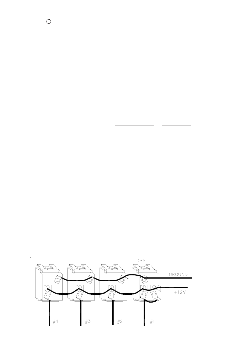
Models 415F, 415PR and 415PO
Use for any control with DPST switch (40 amps) in this position
2
Page 3
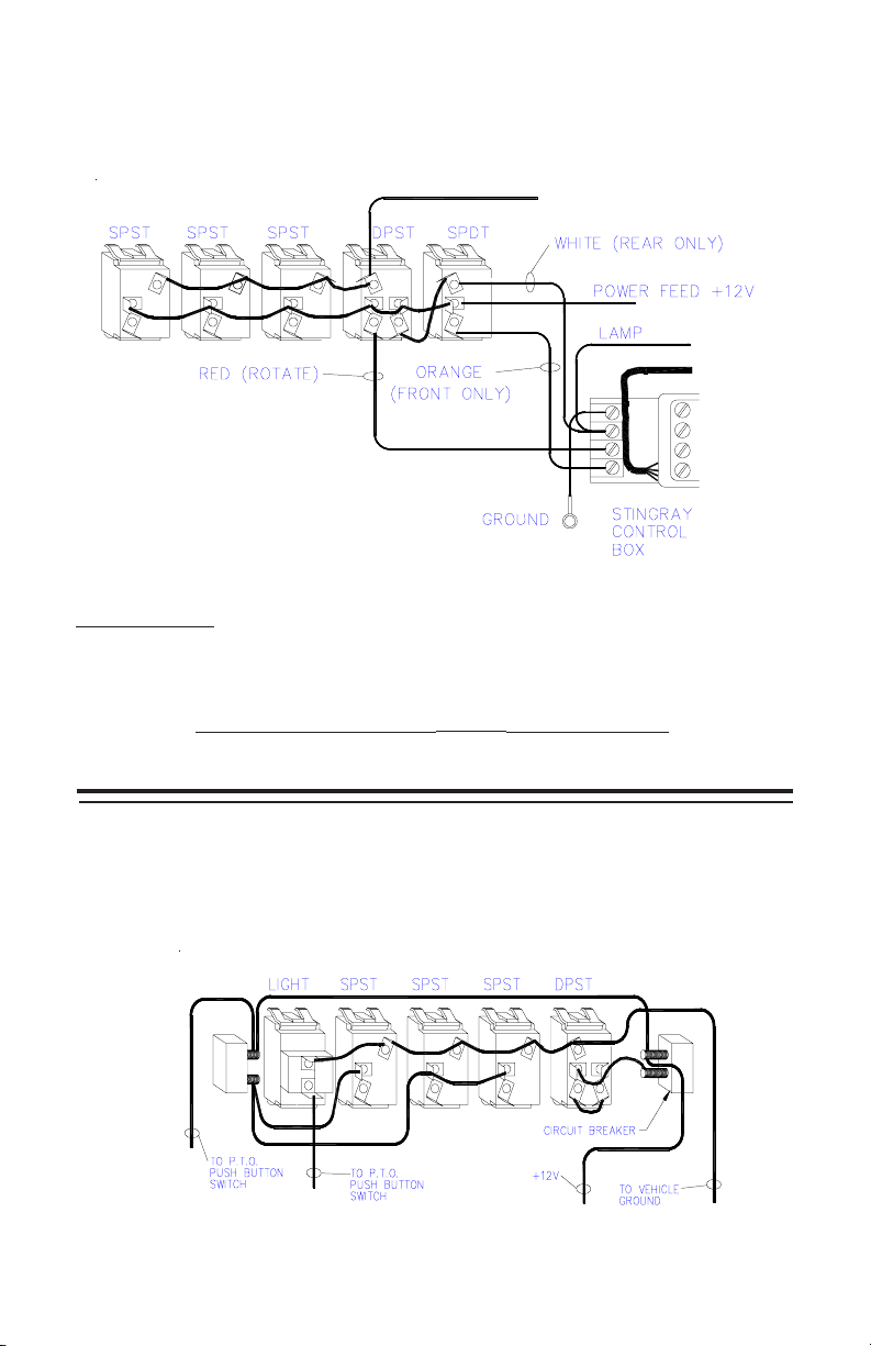
Models 415PS
Use this hook-up for any control having StringRay switching circuits.
GROUND
ddddd
TM
IMPORTANT NOTE:
The STINGRAY and ROTATE switches are
wired together to provide the unique operational
features of the StingRay oscillating signal. These
switches may be activated at the same time; however
ROTATE overrides STINGRAY R (Rear only). STINGRAY F (Front only) overrides
ROTATE and does not operate unless ROTATE is also activated. The ROTATE
switch will be lighted whenever the warning lights are lit.
Model 415T and all models with Circuit Breakers
Use this hook-up (as shown on right) for any control furnished with circuit
breakers. See page 6 for PTO bracket installation.
3
Page 4

Individual Switches Wiring & Hook-up
Rear view of switches- -top is up.
Lighted SPST
P/N T02811
Lighted Progressive
P/N T02824
Lighted SPDT
P/N T02812
Non-Lighted SPST
Momentary
P/N T02813
Lighted DPST
P/N T02821
Non-Lighted SPDT
Momentary
P/N T02815
Non-Lighted DPDT
Radio Rebroadcast
P/N T02823
4
Fuse Stack
P/N S38033
Fuse Stack
P/N S38033
Page 5

RECOMMENDED MINIMUM WIRE SIZES
AMP DRAW MIN. WIRE SIZE
Below 5 #18 AWG
5-8 #16 AWG
9-13 #14 AWG
14-21 #12 AWG
22-36 #10 AWG
NOTE: Larger wires and tight connections will provide longer service life for
switches and improve lighting performance. High ambient temperatures
(e.g. under hood) will significantly reduce the current carrying capacity of wires,
BASED ON 15-FOOT WIRE RUN
fuses and circuit breakers.
PARTS AND SWITCHES
SPST — Single Pole, Single Throw switch; controls a single circuit.
SPDT — Single Pole, Double Throw switch; controls either one or two circuits.
DPST — Double Pole, Single Throw switch; high amperage single circuit.
DPDT — Double Pole, Double Throw switch; for radio rebroadcast.
Radio Rebroadcast — Transfers radio messages to siren speaker.
Momentary — Remains active only while held, springs back to OFF.
Progressive — Turns two functions on or off in a set sequence.
NUMBER TYPE APPLICATION POSITIONS LIGHTED RATING
T02811 SPST Single circuit OFF-ON YES 20 amp
T02812 SPDT Alternate circ. ON-OFF-ON YES 20 amp
T02813 SPST Momentary OFF-MomON NO 8 amp
T02814 Blank Fills hole — NO —
T02815 SPDT Moment/Moment ON-OFF-ON NO 8 amp
T02820 —- Red Indicator Light — YES T02821 DPST High Amperage OFF-ON YES 40 amp
T02822 SPDT StringRay switch ON-OFF-0N NO 20 amp
T02823 DPDT Radio Rebroadcast ON-ON NO 8 amp
T02824 PROG Progressive OFF-ON-ON YES 20 amp
T02838 Auto Reset Circuit Breaker — - 40 amp
T02871 Push Button Switch (415T only) OFF-ON NO 1 amp
T02872 Actuator Disk (PTO unit only)
S38033 Fuse Stack (Factory Upgrade—cannot be field installed)
S38046 Backlighting Assembly (Bulbs with wires only)
S38049 Backlighting Assembly (Complete)
S38093 Floor-mounting Bracket, PTO Control
S25013 RockerPak Mounting Bracket (2 required)
Parts not listed should be purchased locally
5
Page 6

Suggested Mounting with V-Con Siren
R
PTO Mounting Bracket Hook-up
PTO KNOB
PTO CABLE
6
Page 7

N
NOTES
7
Page 8

Code 3, Inc.’s emergency devices are tested and found to be operational at the time of
manufacture. Provided they are installed and operated in accordance with manufacturer’s
recommendations, Code 3, Inc. guarantees all parts and components except the lamps to a
period of 1 year (unless otherwise expressed) from the date of purchase or delivery, whichever
is later. Units demonstrated to be defective within the warranty period will be repaired or
replaced at the factory service center at no cost.
Use of lamp or other electrical load of a wattage higher than installed or recommended
by the factory, or use of inappropriate or inadequate wiring or circuit protection causes this
warranty to become void. Failure or destruction of the product resulting from abuse or unusual
use and/or accidents is not covered by this warranty. Code 3, Inc. shall in no way be liable for
other damages including consequential, indirect or special damages whether loss is due to
negligence or breach of warranty.
CODE 3, INC. MAKES NO OTHER EXPRESS OR IMPLIED WARRANTY INCLUDING,
WITHOUT LIMITATION, WARRANTIES OF FITNESS OR MERCHANTABILITY, WITH
RESPECT TO THIS PRODUCT.
PRODUCT RETURNS
If a product must be returned for repair or replacement*, please contact our factory to obtain
a Return Goods Authorization Number (RGA number) before you ship the product to Code
3, Inc. Write the RGA number clearly on the package near the mailing label. Be sure you
use sufficient packing materials to avoid damage to the product being returned while in
transit.
*Code 3, Inc. reserves the right to repair or replace at its discretion. Code 3, Inc. assumes no responsibility or liability for expenses
incurred for the removal and /or reinstallation of products requiring service and/or repair.; nor for the packaging, handling, and shipping: nor for the
handling of products return to sender after the service has been rendered.
WARRANTY
NEED HELP? Call our Technical Assistance Hotline - (314) 996-2800
St. Louis, Missouri 63114-2029—USA
Revision 4, 01/2006 - Instruction Book Part No.T02887
Code 3 is a registered trademark of Code 3, Inc. a subsidiary of Public Safety Equipment, Inc.
©2000-6 Code 3, Inc. Printed in USA
10986 N. Warson Road
www.code3pse.com
Code 3, Inc.
 Loading...