

Page 1
INSTALLATION
& OPERATION
MANUAL
TM
MODEL 430
Model 430
SWITCH CONTROL
Contents:
Introduction ...................................................... 2
Safety First..................................................................3
Unpacking & Pre-Installation........................... 3
Installation......................................................... 4
Wiring...............................................................5
Parts List ........................................................... 6
Warranty............................................................ 8
TM
IMPORTANT:
Read all instructions and warnings before installing and using.
INSTALLER: This manual must be delivered to the end user of this equipment.
Page 2
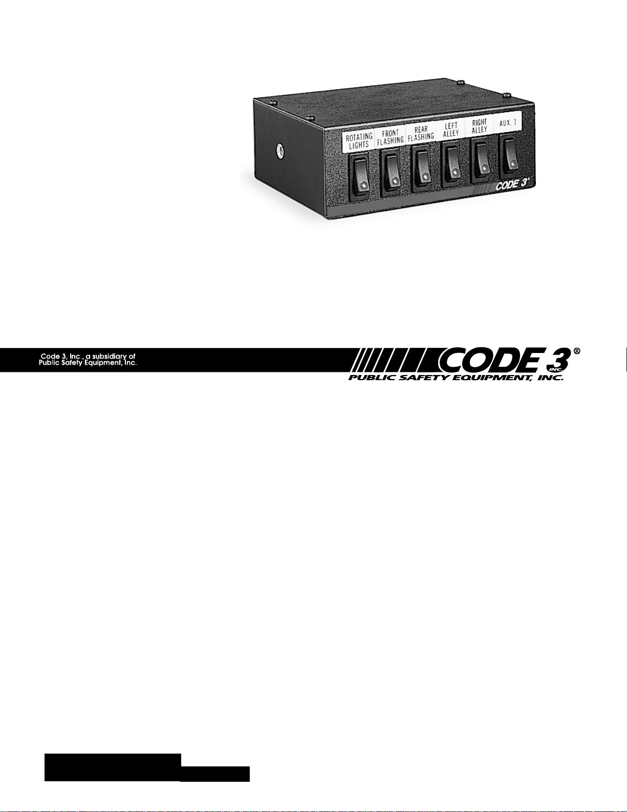
Introduction
The Switch Box switch control panel is designed to accommodate six rocker type switches, which are used to
control various vehicle mounted devices. Six legend inserts are installed above the switches as shown in figure
1 and 2. Six additional legend inserts are included as part of the accessory kit packed with the switch module.
A thermal lock out type circuit breaker, rated at 40 amps, protects the rotating light circuit (#1). The circuit of
one load current is rated at 40 amps. The other circuits (2 through 6) are protected by automotive blade type
fuses rated at 20 amperes.
The switch module is designed to be installed in a vehicle mounting surface to mate with other devices of the
same width.
It can be installed on top of TSD style panels, trunion mount, and many other types of the same width. It may
be used with various models of electronic sirens with the hardware included in the accessory kit, and secured to
the mounting surface with the bracket included with the electronic siren.
Sizes, ratings and switches: the switches are a rugged unit and rated at 20 amperes @ 12 VDC. The panel's
dimensions are 2 3/16" x 6 1/16" x 5 7/8" (including fuses). Overall weight of the unit is 2 pounds.
FIGURE 1
!
WARNING!
The use of this or any warning device does not insure that all drivers can or will observe or
react to an emergency warning signal. Never take the right-of-way for granted. It is your
responsibility to be sure you can proceed safely before entering an intersection, driving
against traffic, responding at a high rate of speed, or walking on or around traffic lanes.
The effectiveness of this warning device is highly dependent upon correct mounting and
wiring. Read and follow the manufacturer’s instructions before installing or using this
device. The vehicle operator should insure daily that all features of the device operate
correctly. In use, the vehicle operator should insure the projection of the warning signal is
not blocked by vehicle components (i.e.: open trunks or compartment doors), people,
vehicles, or other obstructions.
This equipment is intended for use by authorized personnel only. It is the user’s responsibility to understand and obey all laws regarding emergency warning devices. The user
should check all applicable city, state and federal laws and regulations.
Public Safety Equipment, Inc., assumes no liability for any loss resulting from the use of
this warning device.
Proper installation is vital to the performance of this warning device and the safe operation
of the emergency vehicle. It is important to recognize that the operator of the emergency
vehicle is under psychological and physiological stress caused by the emergency situation.
The warning device should be installed in such a manner as to: A) Not reduce the output
performance of the system, B) Place the controls within convenient reach of the operator
so that he can operate the system without losing eye contact with the roadway.
Emergency warning devices often require high electrical voltages and/or currents. Properly
protect and use caution around live electrical connections. Grounding or shorting of
electrical connections can cause high current arcing, which can cause personal injury and/
or severe vehicle damage, including fire. Incandescent lamps are extremely hot, allow to
cool completely before attempting to remove.
Any electronic device may create or be affected by electromagnetic interference. After
installation of any electronic device operate all equipment simultaneously to insure that
operation is free of interference. Never power emergency warning equipment from the
same circuit or share the same grounding circuit with radio communication equipment.
PROPER INSTALLATION COMBINED WITH OPERATOR TRAINING IN THE PROPER
USE OF EMERGENCY WARNING DEVICES IS ESSENTIAL TO INSURE THE SAFETY
OF EMERGENCY PERSONNEL AND THE PUBLIC.
2
Page 3
Safety First
Installers should keep in mind the importance of safe installation to protect the lives of those who may depend
upon this equipment. Please read all instructions supplied with this equipment. Listed below are some other
important safety instructions to follow:
To properly install the equipment described in this instruction sheet: you must have a good
understanding of automotive electrical procedures and systems, along with proficiency in the
installation and use of safety warning equipment.
Locate the switch module so the vehicle and controls can be operated safely under all driving
conditions.
When drilling into a vehicle structure, be sure that both sides of the surface are clear of anything
that could be damaged.
Keep these instructions in a safe place and refer to them when maintaining and/or reinstalling the
product.
Failure to follow all safety precautions and instructions may result in property damage, serious injury, or death
to you or others.
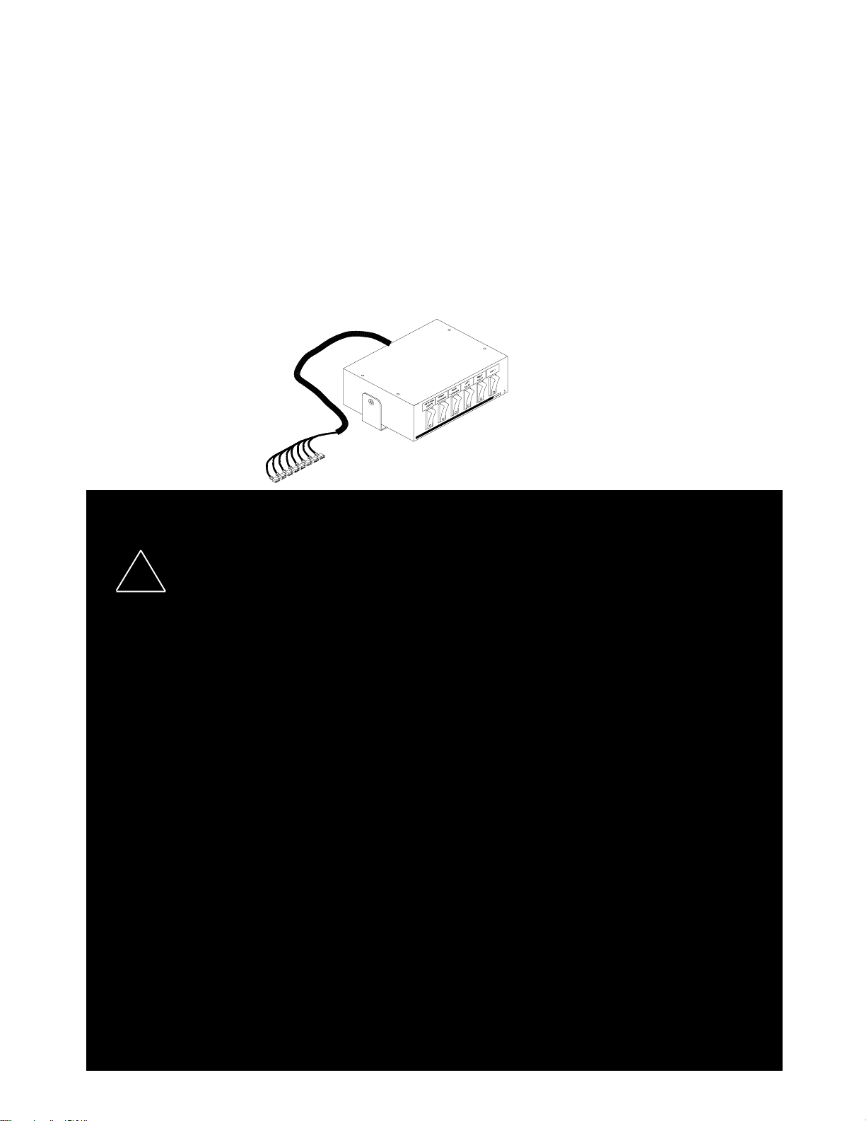
Unpacking & Pre-installation
Carefully remove the Switch Control from the shipping carton and place on a flat surface, taking care not to
damage the wire cable coming out of the back of control box. Examine the unit for transit damage, dented
cover, ect.. If convenient, you may wish to bench test the unit before installing. Before applying voltage to the
bar, be sure you have read and understand the wiring instructions on page 5.
FIGURE 2
3
Page 4
Installation
All devices should be mounted in accordance with the manufacturer's instructions and
securely fasten to vehicle elements of sufficient strength to withstand the forces applied to
!
WARNING!
WARNING!
To install the Switch Box follow the installation instructions. There are several ways you may install this unit,
but if it is installed with the TSD trunion mounting bracket, you will need to follow the instructions provided for
the "CO" series brackets.
If you choose to mount this unit by a bail bracket (not provided), then follow the instructions that come with our
bail brackets.
The Switch Box may be mounted on top of or below a siren system. If this is your choice, then follow
the instructions below:
the device. Driver and/or passenger air bags (SRS) will affect the way equipment should
be mounted. This device should be mounted by permanent installation and within the
zones specified by the vehicle manufacturer, if any. Any device mounted in the deployment area of an air bag will damage or reduce the effectiveness of the air bag and may
damage or dislodge the device. Installer must be sure that this device, its mounting
hardware and electrical supply wiring does not interfere with the air bag or the SRS wiring
or sensors. Front or rear grille/bumper placement must avoid interference with SRS
sensors. Mounting the unit inside the vehicle by a method other than the permanent
installation is not recommended as unit may become dislodged during swerving, sudden
braking, or collision. Failure to follow instructions can result in personal injury.
1) Select a mounting location which allows the vehicle and all controls to be
operated safely under all driving conditions.
2) Choose an adequately ventilated area. Never install near heat ducts or totally
enclosed areas.
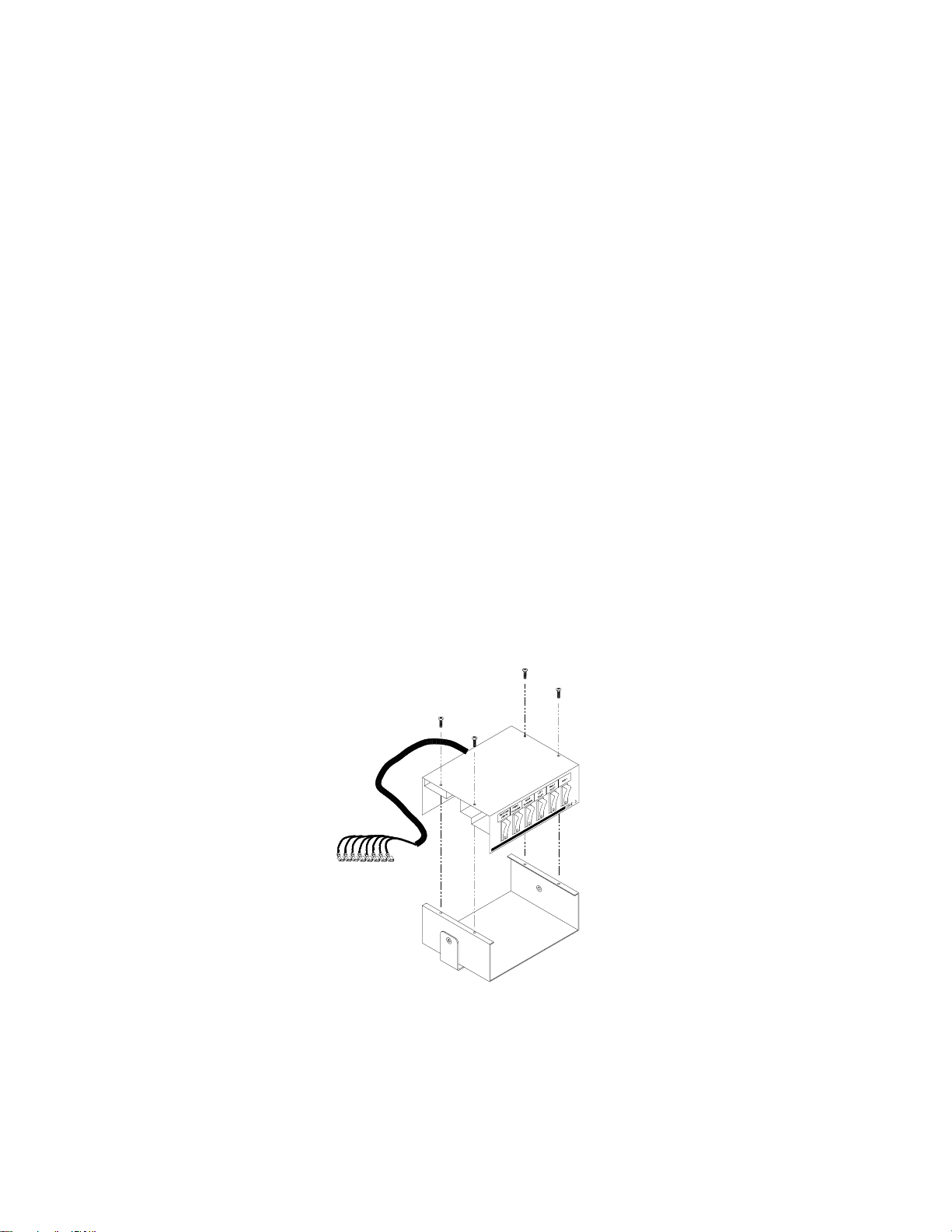
3) Arrange the bottom of the switch control unit so that it is even with the siren face
module. Fasten the two units together with trunion mounts or brackets (not provided)
from both sides. You may need to remove the switch control for the housing. If this is
the case, it will require the removal of four phillips head screws located on top of the
switch control housing.
4) Secure the case with 1/4" - 20 x 5/8" hex head screws and 1/4" split lockwasher
(provided in kit). Do not tighten securely until a proper angle is positioned for safe
operator visibility.
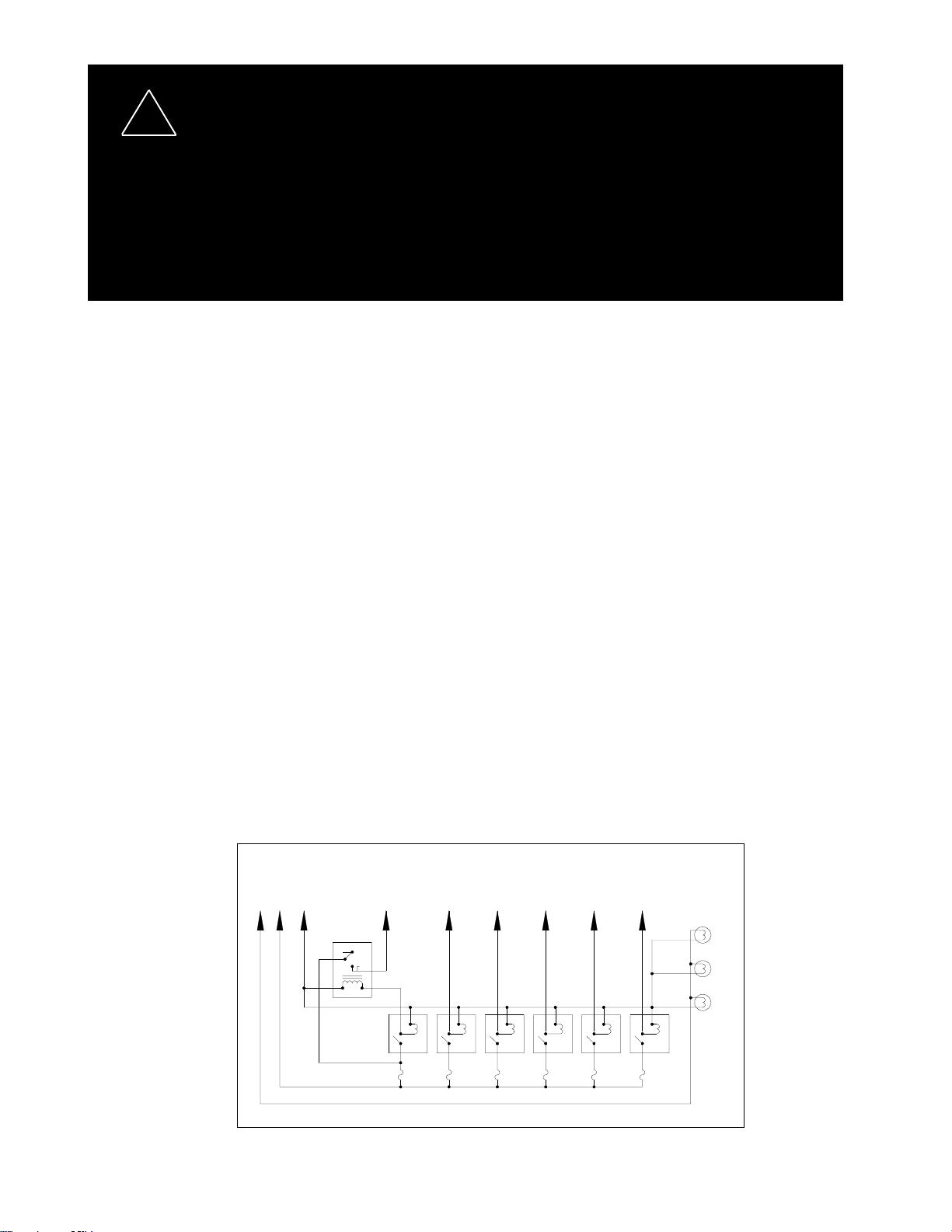
B H G 1 2 3 4 5 6 PANEL
+ + GND LIGHTS
BATT.
F1 F2 F3 F4 F5 F6
+ BATTERY 40A 20A 20A 20A 20A 20A
BACK LIGHTING
WIRING DIAGRAM
FIGURE 3
4
Page 5

WARNING!
Wiring
!
WARNING!
5) Tilt the unit to the desired position and tighten the 1/4" - 20 x 3/8" hex head
screws.
6) Use the mounting bracket as a templet and position for two hole by marking the
position with a scribe. Drill holes for positioning the mounting bracket.
CAUTION: When drilling holes in any part of the vehicle, make sure that both sides
of the surface are clear of parts that could be damaged; such as brake lines,
electrical wiring, fuel lines, or other vital parts of the vehicle.
7) Drill two 1/4" diameter holes at the position marked.
8) Secure the mounting bracket in place. Make sure all positions are tight and
screws secured in place.
NOTE: Many other locations may be of better choice for your operation. If other
locations are selected, use every precautionary measure to safely install to prevent
damage to the vehicle.
Larger wires and tight connections will provide longer service life for components. For high
current wires it is highly recommended that terminal blocks or soldered connections be used
with shrink tubing to protect the connections. Do not use insulation displacement
connectors (e.g. 3M® Scotchlock type connectors). Route wiring using grommets and
sealant when passing through compartment walls. Minimize the number of splices to
reduce voltage drop. High ambient temperatures (e.g. underhood) will significantly reduce
the current carrying capacity of wires, fuses, and circuit breakers. Use "SXL" type wire in
engine compartment. All wiring should conform to the minimum wire size and other
recommendations of the manufacturer and be protected from moving parts and hot
surfaces. Looms, grommets, cable ties, and similar installation hardware should be used to
anchor and protect all wiring.
Fuses or circuit breakers should be located as close to the power takeoff points as possible
and properly sized to protect the wiring and devices.
Particular attention should be paid to the location and method of making electrical
connections and splices to protect these points from corrosion and loss of conductivity.
Ground terminations should only be made to substantial chassis components, preferably
directly to the vehicle battery.
The user should install a fuse sized to approximately 125% of the maximum Amp capacity
in the supply line to protect against short circuits. For example, a 30 Amp fuse should
carry a maximum of 24 Amps. DO NOT USE 1/4" DIAMETER GLASS FUSES AS THEY
ARE NOT SUITABLE FOR CONTINUOUS DUTY IN SIZES ABOVE 15 AMPS. Circuit
breakers are very sensitive to high temperatures and will "false trip" when mounted in hot
environments or operated close to their capacity.
Figure 2 illustrates the correlation of tagged wires to a corresponding operation. Example: Switch one (starting
from left to right) controls the electronic operation of the wire tagged as #1.
Insulated male terminals, which mate with the female terminals on the switch module wiring harness, have
been included in the accessory kit to facilitate installation. These terminals should be installed on the end of
the lead wire which will mate with the wiring harness lead wire. Use yellow terminals for 10-12 AWG wire and
pink terminals for 18-22 AWG wire.
NOTE: When using the insulated terminals, insure that all crimps are secure and that the male/female
terminals slip into each other and not over each other.
5
Page 6

To properly wire the switch module, see the wiring diagram shown in figure 3 and perform the following
procedures:
1) Use 12 AWG wire and connect leads "1" through "6" to the applicable accessory
load. Remember: lead "1" corresponds to switch "1", lead "2" to switch "2", and so
on.
2) Use 18 AWG wire and connect the ground (earth) lead "G" to a reliable ground
(earth). Each switched device must be grounded with a separate ground (earth) wire.
3) Use 18 AWG wire and connect the backlighting circuit lead "B" to the accessory
terminal of the ignition switch or the vehicle instrument light circuit.
4) Power for the switch module may be obtained from a vehicle power distribution
center (TSD part number D1X1F-PD90) or by a 60, 80, or 100 amp master circuit
breaker (call TSD for part number required). We recommend that all circuits be
protected by fuses or circuit breakers. Installation of a power distribution center or
master circuit breaker should be placed near the battery. Use 8 AWG wire and
connect the power distribution center. If power is obtained in the engine
compartment, a hole will probably have to be drilled into the vehicle firewall. Place a
grommet or similar device in the hole to protect the wire (S) against damage from
rough edges.
CAUTION: When drilling holes in any part of any of the vehicle, ensure that both sides of the surface are clear
of parts that could be damaged: such as brake lines, electrical wiring, fuel lines, or any other vital part of the
vehicle.
Parts List
Description Qty.
1/4" - 20 x 5/8" bolts 2
1/4" lock washer 2
wire ties 2
insulated 1/4" male terminals (yellow) 7
insulated 1/4" male terminals (pink) 2
legend inserts, (TAKE DOWN, GRILLE LIGHTS, DECK LIGHTS, 8
STROBE,AUX., WIGWAG, FRT/REAR FLASHER, (CENTER &
SWEEPS))
6
Page 7

NOTES
7
Page 8

WARRANTY
This product was tested and found to be operational at the time of manufacture. Provided this product is
installed and operated in accordance with the manufacturer's recommendations, Public Safety Equipment
guarantees all parts and components except the lamps for a period of 1 year from the date of purchase or
delivery, whichever is later. Units demonstrated to be defective within the warranty period will be repaired or
replaced at the factory service center at no cost.
Use of a lamp or other electrical load of a wattage higher than installed or recommended by the factory,
or use of inappropriate or inadequate wiring or circuit protection causes this warranty to become void. Failure
or destruction of the product resulting from abuse or unusual use and/or accidents is not covered by this
warranty.
PSE shall in no way be liable for other damages including consequential, indirect or special damages
whether loss is due to negligence or breach of warranty.
PSE MAKES NO OTHER EXPRESS OR IMPLIED WARRANTY INCLUDING, WITHOUT LIMITATION, WARRANTIES OF FITNESS OR MERCHANTABILITY, WITH RESPECT TO THIS PRODUCT.
PRODUCT RETURNS
If a product must be returned for repair or replacement*, please contact our factory to obtain
a Return Goods Authorization Number (RGA number) before you ship the product to Code 3, Inc.
Write the RGA number clearly on the package near the mailing label. Be sure you use sufficient
packing materials to avoid damage to the product being returned while in transit.
*Code 3, Inc. reserves the right to repair or replace at its discretion. Code 3, Inc. assumes no responsibility or liability for expenses incurred for the
removal and /or reinstallation of products requiring service and/or repair.; nor for the packaging, handling, and shipping: nor for the handling of products return to
sender after the service has been rendered.
Public Safety Equipment, Inc.
St. Louis, Missouri 63114-2029USA
Ph. (314) 426-2700 Fax (314) 426-1337
10986 N. Warson Road
www.code3pse.com
Code 3 is a registered trademarks of
Public Safety Equipment, Inc.
Revision 3, 10/01 - Instruction Book Part No. T04922
©2001 Public Safety Equipment, Inc. Printed in USA
Page 9

Wiring
&
Installation
Guide
415 Series
Rocker Switch
Control Panels
Contents:
DESCRIPTION PAGE
GENERAL INSTRUCTIONS 2
MODEL 415F 2
MODEL 415PO 2
MODEL 415PR 2
MODEL 415PS 3
MODEL 415T 3
STINGRAY HOOK-UP 3
PARTS AND SWITCHES 5
WIRE REQUIREMENTS 5
MOUNTING WITH SIREN 6
PTO HOOK-UP 6
Page 10

The Code 3 RockerPak Series Lighting Control is a reliable and versatile
unit with options that allow customized switch packages. The variety of final
products is too great to be shown here in its entirety, but factory wiring
makes the installation similar to the following examples in most cases.
R
The Code 3 RockerPak Series Lighting Control
is a reliable and versatile
General Instructions
1. Determine whether your control unit should be wired from the vehicle's
battery or ignition circuitry, depending on the need for security and/or total
access.
2. See the hook-up details for your model(s) as shown below. If you have a
non-standard model, use the hook-up for the model having the same switch
in the position illustrated.
3. Use #10 A.W.G. wire feed +(POS)12-volt supply to circuit breaker or
fuse, then to switch unit. Circuit protection should be rated at 125% of the
total load. Units with factory installed circuit breakers or fuse stacks may be
straight wired without additional protection.
4. Units with Legend Backlighting may be hooked up as provided if you
choose to operate the system from the ignition circuit. If you plan to operate
with the switches always live, carefully cut the single red feed line to the
backlighting light bulbs and use a butt-splice connector to provide power
from the ignition circuit to prevent battery discharge. Remove the cut off end
to prevent short circuits.
5. IMPORTANT: You will save time and protect the switches from damage
by carefully aligning the male and female spade connectors before inserting.
Use free hand on the rocker switch face to oppose insertion force.
6. Connect from vehicle chassis to switch unit ground (black wire) using #18
A.W.G. wire.
7. Connect each switch to the appropriate device using recommended wire
sizes from the table on page 5, with fuses rated at 125% of each individual
wire load. Do not fuse higher than the switch rating.
Models 415F, 415PR and 415PO
Use for any control with DPST switch (40 amps) in this position
2
Page 11

Models 415PS
Use this hook-up for any control having StringRay switching circuits.
GROUND
ddddd
TM
IMPORTANT NOTE:
The STINGRAY and ROTATE switches are
wired together to provide the unique operational
features of the StingRay oscillating signal. These
switches may be activated at the same time; however
ROTATE overrides STINGRAY R (Rear only). STINGRAY F (Front only) overrides
ROTATE and does not operate unless ROTATE is also activated. The ROTATE
switch will be lighted whenever the warning lights are lit.
Model 415T and all models with Circuit Breakers
Use this hook-up (as shown on right) for any control furnished with circuit
breakers. See page 6 for PTO bracket installation.
1
3
Page 12

Individual Switches Wiring & Hook-up
Rear view of switches- -top is up.
Lighted SPST
P/N T02811
Lighted Progressive
P/N T02824
Lighted SPDT
P/N T02812
Non-Lighted SPST
Momentary
P/N T02813
Lighted DPST
P/N T02821
Non-Lighted SPDT
Momentary
P/N T02815
Non-Lighted DPDT
Radio Rebroadcast
P/N T02823
4
Fuse Stack
P/N S38033
Fuse Stack
P/N S38033
Page 13

RECOMMENDED MINIMUM WIRE SIZES
AMP DRAW MIN. WIRE SIZE
Below 5 #18 AWG
5-8 #16 AWG
9-13 #14 AWG
14-21 #12 AWG
22-36 #10 AWG
NOTE: Larger wires and tight connections will provide longer service life for
switches and improve lighting performance. High ambient temperatures
(e.g. under hood) will significantly reduce the current carrying capacity of wires,
BASED ON 15-FOOT WIRE RUN
fuses and circuit breakers.
PARTS AND SWITCHES
SPST Single Pole, Single Throw switch; controls a single circuit.
SPDT Single Pole, Double Throw switch; controls either one or two circuits.
DPST Double Pole, Single Throw switch; high amperage single circuit.
DPDT Double Pole, Double Throw switch; for radio rebroadcast.
Radio Rebroadcast Transfers radio messages to siren speaker.
Momentary Remains active only while held, springs back to OFF.
Progressive Turns two functions on or off in a set sequence.
NUMBER TYPE APPLICATION POSITIONS LIGHTED RATING
T02811 SPST Single circuit OFF-ON YES 20 amp
T02812 SPDT Alternate circ. ON-OFF-ON YES 20 amp
T02813 SPST Momentary OFF-MomON NO 8 amp
T02814 Blank Fills hole NO
T02815 SPDT Moment/Moment ON-OFF-ON NO 8 amp
T02820 - Red Indicator Light YES T02821 DPST High Amperage OFF-ON YES 40 amp
T02822 SPDT StringRay switch ON-OFF-0N NO 20 amp
T02823 DPDT Radio Rebroadcast ON-ON NO 8 amp
T02824 PROG Progressive OFF-ON-ON YES 20 amp
T02838 Auto Reset Circuit Breaker - 40 amp
T02871 Push Button Switch (415T only) OFF-ON NO 1 amp
T02872 Actuator Disk (PTO unit only)
S38033 Fuse Stack (Factory Upgradecannot be field installed)
S38046 Backlighting Assembly (Bulbs with wires only)
S38049 Backlighting Assembly (Complete)
S38093 Floor-mounting Bracket, PTO Control
S25013 RockerPak Mounting Bracket (2 required)
Parts not listed should be purchased locally
5
Page 14

Suggested Mounting with V-Con Siren
R
PTO Mounting Bracket Hook-up
PTO KNOB
PTO CABLE
6
Page 15

N
NOTES
7
Page 16

Code 3, Inc.s emergency devices are tested and found to be operational at the time of manufacture.
Provided they are installed and operated in accordance with manufacturers recommendations, Code 3, Inc.
guarantees all parts and components except the lamps to a period of 1 year (unless otherwise expressed) from the
date of purchase or delivery, whichever is later. Units demonstrated to be defective within the warranty period will
be repaired or replaced at the factory service center at no cost.
Use of lamp or other electrical load of a wattage higher than installed or recommended by the factory, or use
of inappropriate or inadequate wiring or circuit protection causes this warranty to become void. Failure or destruction
of the product resulting from abuse or unusual use and/or accidents is not covered by this warranty. Code 3, Inc. shall
in no way be liable for other damages including consequential, indirect or special damages whether loss is due to
negligence or breach of warranty.
CODE 3, INC. MAKES NO OTHER EXPRESS OR IMPLIED WARRANTY INCLUDING,
WITHOUT LIMITATION, WARRANTIES OF FITNESS OR MERCHANTABILITY, WITH
RESPECT TO THIS PRODUCT.
PRODUCT RETURNS
If a product must be returned for repair or replacement*, please contact our factory to
obtain a Return Goods Authorization Number (RGA number) before you ship the product
to Code 3, Inc. Write the RGA number clearly on the package near the mailing label. Be
sure you use sufficient packing materials to avoid damage to the product being returned
while in transit.
*Code 3, Inc. reserves the right to repair or replace at its discretion. Code 3, Inc. assumes no responsibility or liability for expenses incurred for the removal
and /or reinstallation of products requiring service and/or repair.; nor for the packaging, handling, and shipping: nor for the handling of products return to sender after the service
has been rendered.
WARRANTY
8
Public Safety Equipment, Inc.
St. Louis, Missouri 63114-2029USA
Ph. (314) 426-2700 Fax (314) 426-1337
Revision C, 11/00 - Instruction Book Part No.T02887
©2000 Public Safety Equipment, Inc. Printed in USA
10986 N. Warson Road
Code 3,® Inc., a subsidiary of
Public Safety Equipment, Inc.
Page 17

INSTALLATION
& OPERATION
MANUAL
Introduction
The 416 Switchbox is a 6 switch control center
without circuit breakers. The model 426 is the same
6 switch control center protected by 3 circuit breakers.
The 426 also offers backlighting as standard
equipment. Backlighting is optional on the 416.
Procedure
Wiring Instructions:
1) The installer needs to first determine the
current load in amps of each of the devices
to be switched by the Switchbox.
2) Connect the devices to the desired switch,
noting the current limitations of each switch
and group of switches.
3) An 8 gauge wire should be run from the
Red 8 gauge Switchbox input wire to a
user supplied fuse, then to the (+) side of
the battery, the alternator, or the stud on
the battery side of the solenoid. The user
supplied fuse should be located as close
to the battery as possible and sized to
125% of the total load carried by the
Switchbox (i.e.: if the total load carried is
40 amps; 40 amps x 125% = 50 amp fuse).
A circuit breaker is not recommended
here, they are very sensitive to high
ambient temperatures and will false trip
416 Switchbox
4) Connect the black wire to vehicle chassis
Larger wires and tight connections (crimp
!
WARNING!
Customer supplied
fuse (sized to 125%)
40 amp
breaker
MODEL 416/ 426
SWITCHBOX
when mounted in hot environments or
operated close to their capacity. Do not use
1/4" dia. glass fuses as they are not suitable
for continuous duty in sizes above 15 amps.
(earth).
connectors perform poorly over time) will
provide longer service life for components. It
is highly recommended that terminal blocks
or soldered connections be used with shrink
tubing to protect the connections. Do not use
insulation displacement connectors (e.g. 3M®
Scotchlock type connectors). Route wiring
using grommets and sealant when passing
through compartment walls. Minimize the
number of splices to reduce voltage drop.
High ambient temperatures (e.g. under hood)
will significantly reduce the current carrying
capacity of wires, fuses, and circuit breakers.
Use "SXL" type wire in engine compartments.
426 Switchbox
Battery
(+) 12 Volt ignition circuit
white/ black wire
Vehicle chassis (earth)
18 ga. black wire
8 ga red input
20 amp
breaker
Panel backlighting
20 amp
breaker
Customer supplied
fuse (sized to 125%)
8 ga red
input
32 amps 16 amps 16 amps 10 amps 10 amps 10 amps
32 amps 16 amps 16 amps
Battery
10 ga.
red/ black
55 amps max load for entire Switchbox
14 ga.
white
2
IMPORTANT:
16 ga.
yellow/
black
6
16 ga.
orange
14 ga.
purple
3
16 ga.
16 ga.
yellow/
blue
45
black
Vehicle chassis (earth)
18 ga. black wire
16 ga.
orange
61
10 ga.
red/ black
1
32 amps 16 amps 16 amps 10 amps 10 amps 10 amps
32 amps
55 amps max load for entire Switchbox
14 ga.
white
2
16 amps 16 amps
14 ga.
purple
3
16 ga.
blue
4
5
Read all instructions and warnings before installing and using.
INSTALLER: This manual must be delivered to the end user of this equipment.
Page 18

!
WARNING!
The use of this or any warning device does not insure that all drivers can or will observe or
react to an emergency warning signal. Never take the right-of-way for granted. It is your
responsibility to be sure you can proceed safely before entering an intersection, driving
against traffic, responding at a high rate of speed, or walking on or around traffic lanes.
The effectiveness of this warning device is highly dependent upon correct mounting and
wiring. Read and follow the manufacturers instructions before installing or using this device.
The vehicle operator should insure daily that all features of the device operate correctly. In
use, the vehicle operator should insure the projection of the warning signal is not blocked by
vehicle components (i.e.: open trunks or compartment doors), people, vehicles, or other
obstructions.
This equipment is intended for use by authorized personnel only. It is the users responsibility to understand and obey all laws regarding emergency warning devices. The user should
check all applicable city, state and federal laws and regulations.
Public Safety Equipment, Inc., assumes no liability for any loss resulting from the use of
this warning device.
2
Page 19

NOTES
3
Page 20

WARRANTY
This product was tested and found to be operational at the time of manufacture. Provided this product
is installed and operated in accordance with the manufacturer's recommendations, Public Safety Equipment
guarantees all parts and components except the lamps for a period of 1 year from the date of purchase or
delivery, whichever is later. Units demonstrated to be defective within the warranty period will be repaired or
replaced by the factory or at a factory authorized service center at no cost.
Use of a lamp or other electrical load of a wattage higher than installed or recommended by the factory
causes this warranty to become void. Failure or destruction of the product resulting from abuse or unusual
use and/or accidents is not covered by this warranty.
PSE shall in no way be liable for other damages including consequential, indirect or special damages
whether loss is due to negligence or breach of warranty.
PSE MAKES NO OTHER EXPRESS OR IMPLIED WARRANTY INCLUDING, WITHOUT LIMITATION,
WARRANTIES OF FITNESS OR MERCHANTABILITY, WITH RESPECT TO THIS PRODUCT.
PRODUCT RETURNS
In order to provide you with faster service, if you are going to return a product for repair or replacement*, please contact our factory to obtain a Return Goods Authorization Number (RGA number) before you
ship the product to PSE. Write the RGA number clearly on the package near the mailing label. Be sure you
use sufficient packing materials to avoid damage to the product being returned while in transit.
*PSE reserves the right to repair or replace product at its discretion. PSE assumes no responsibility or liability for
expenses incurred for the removal and/or reinstallation of products requiring service and/or repair.
Code 3 is a registered trademark of Public Safety Equipment, Inc.
3M is a registered trademark of 3M Company, Inc.
Public Safety Equipment, Inc.
St. Louis, Missouri 63114-2029USA
Ph. (314) 426-2700 Fax (314) 426-1337
Revision 4, 5/02 - Instruction Book Part N0 T06581
©2002 Public Safety Equipment, Inc. Printed in USA
10986 N. Warson Road
www.code3pse.com
 Loading...