

Page 1
INSTALLATION &
OPERATION
MANUAL
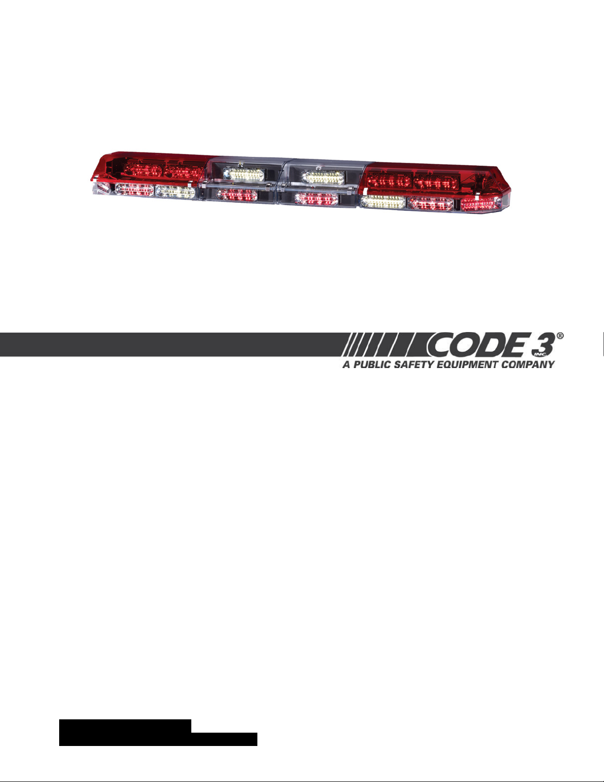
FOR RMX™ LIGHTBAR
WITH PRIZM II™ LIGHT HEADS
™
RMX
LIGHT BAR
CONTENTS:
Introduction............................................................................................2
Unpacking & Pre-Installation...................................................................3
Installation & Mounting............................................................................3
Wiring Instructions...............................................................................3-4
Options & Specifi cations......................................................................4-6
Maintenance.......................................................................................6-8
Parts List (Replacement Parts/Exploded View)....................................9-10
Troubleshooting...............................................................................11
Warranty/Returns.................................................................................12
For future reference record your lightbar's serial no. here __________________________________________
IMPORTANT:
Read all instructions and warnings before installing and using.
INSTALLER: This manual must be delivered to the end user of this equipment.
1
Page 2
Introduction
The RMX™ Lightbar is approximately 5.4" high and delivers 360° of unobstructed warning signal. PriZm II™ refl ector technology
means more signal power and versatility than any other lightbar of its size.
The aerodynamic lines reduce air drag, which results in fuel savings and stability at high speeds. This lightbar has a strong extruded
internal frame, shock-resistant polycarbonate lenses, and warning signals that exceed SAE standards.
The RMX has room for numerous LED options. While we do not recommend a light installed in every location, the design of the RMX
offers the ultimate fl exibility in the location of warning and auxiliary lights.
The use of this or any warning device does not ensure that all drivers can or will observe or react to an
emergency warning signal. Never take the right-of-way for granted. It is your responsibility to be sure you can
proceed safely before entering an intersection, driving against traffi c, responding at a high rate of speed, or
walking on or around traffi c lanes.
WARNING!
The effectiveness of this warning device is highly dependent upon correct mounting and wiring. Read and
follow the manufacturer’s instructions before installing or using this device. The vehicle operator should insure
daily that all features of the device operate correctly. In use, the vehicle operator should insure the projection
of the warning signal is not blocked by vehicle components (i.e.: open trunks or compartment doors), people,
vehicles, or other obstructions.
This equipment is intended for use by authorized personnel only. It is the user’s responsibility to understand
and obey all laws regarding emergency warning devices. The user should check all applicable city, state and
federal laws and regulations.
Code 3, Inc., assumes no liability for any loss resulting from the use of this warning device.
Proper installation is vital to the performance of this warning device and the safe operation of the emergency
vehicle. It is important to recognize that the operator of the emergency vehicle is under psychological and
physiological stress caused by the emergency situation. The warning device should be installed in such a
manner as to: A) Not reduce the output performance of the system, B) Place the controls within convenient
reach of the operator so that he can operate the system without losing eye contact with the roadway.
Emergency warning devices often require high electrical voltages and/or currents. Properly protect and use
caution around live electrical connections. Grounding or shorting of electrical connections can cause high current arcing, which can cause personal injury and/or severe vehicle damage, including fi re.
PROPER INSTALLATION COMBINED WITH OPERATOR TRAINING IN THE PROPER USE OF EMERGENCY WARNING DEVICES IS ESSENTIAL TO ENSURE THE SAFETY OF EMERGENCY PERSONNEL AND
THE PUBLIC.
Wiring Instructions (Read Carefully Before Installation)
2
Page 3

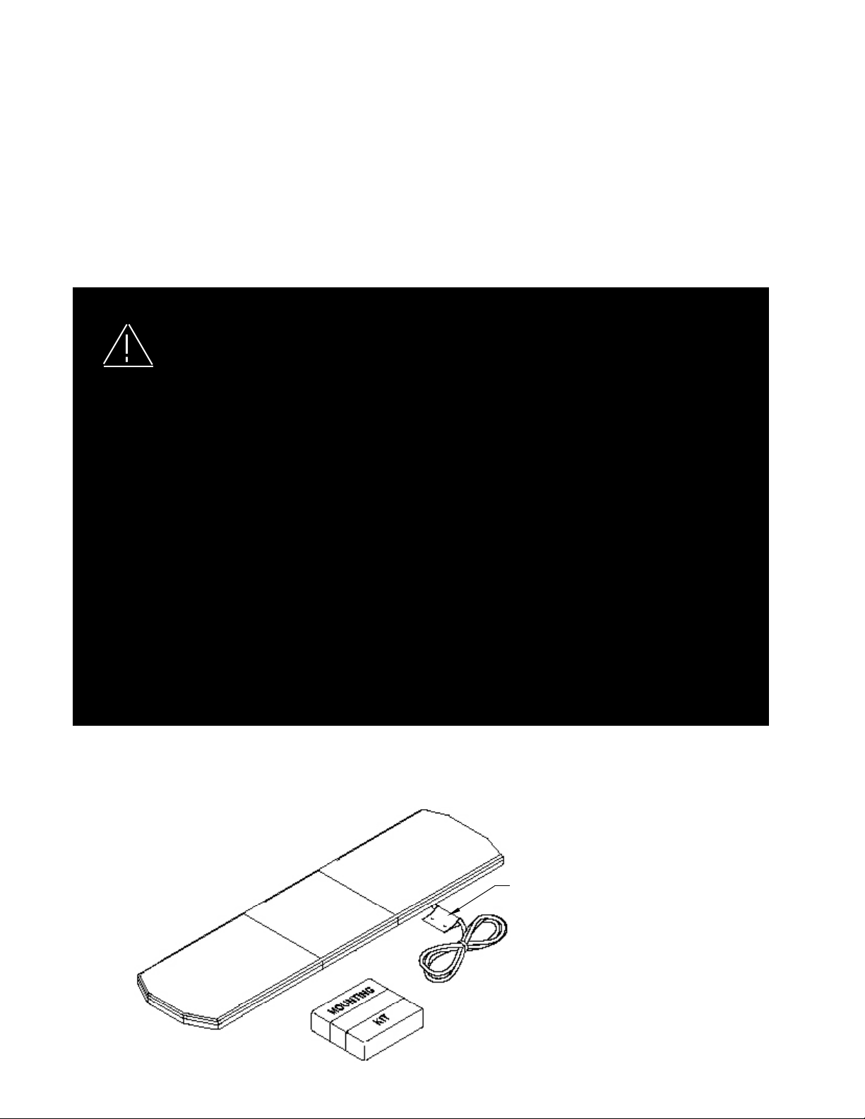
Unpacking & Pre-Installation
Carefully remove the lightbar and place it on a fl at surface, taking care not to scratch the lenses or damage the cable coming out of
the bottom. Examine the unit for transit damage, broken lamps, etc. Report any damage to the carrier and keep the shipping carton.
Standard lightbars are built to operate on 12 volt D.C. negative ground (earth) vehicles. If you have an electrical system other than 12
volt D.C. negative ground (earth), and have not ordered a specially wired lightbar, contact the factory for instructions.
Test the unit before installation. To test, touch the black wire to the ground (earth) and the other wires to +12 volts D.C., in accordance
with the instructions attached to the cable (an automotive battery is preferable for this test). A battery charger may be used, but please
note that some electronic options (fl ashers, etc.) may not operate normally when powered by a battery charger. If problems occur at
this point, contact the factory.
Installation & Mounting
Utilizing non-factory supplied screws and/or mounting brackets and/or the improper number
of screws may result in loss of warranty coverage on the equipment.
WARNING!
MOUNTING HARDWARE - Mounting hardware is usually packed in a small box inside the main carton although some mounting kits
may be shipped separately. Refer to the Installation Manual included in the mounting kit for mounting instructions. Note: Hook-on
mounting for "gutterless" type vehicles will require a special hook for mounting. Several special application hooks are available. Contact the factory for details.
Wiring Instructions
Larger wires and tight connections will provide longer service life for components. For high current wires it
is highly recommended that terminal blocks or soldered connections be used with shrink tubing to protect
the connections. Do not use insulation displacement connectors (e.g. 3M® Scotchlock type connectors).
Route wiring using grommets and sealant when passing through compartment walls. Minimize the number
WARNING!
Before attempting to connect wiring, refer to wire tag attached to the lightbar's main cable. Each wire in the cable controls a
separate lightbar function as described in the wire tag.
of splices to reduce voltage drop. High ambient temperatures (e.g. underhood) will signifi cantly reduce the
current carrying capacity of wires, fuses, and circuit breakers. Use "SXL" type wire in engine compartment.
All wiring should conform to the minimum wire size and other recommendations of the manufacturer and
be protected from moving parts and hot surfaces. Looms, grommets, cable ties, and similar installation
hardware should be used to anchor and protect all wiring. Fuses or circuit breakers should be located as
close to the power takeoff points as possible and properly sized to protect the wiring and devices. Particular
attention should be paid to the location and method of making electrical connections and splices to protect
these points from corrosion and loss of conductivity. Ground terminations should only be made to substantial chassis components, preferably directly to the vehicle battery. The user should install a fuse sized
to approximately 125% of the maximum Amp capacity in the supply line to protect against short circuits.
For example, a 30 Amp fuse should carry a maximum of 24 Amps. DO NOT USE 1/4" DIAMETER GLASS
FUSES AS THEY ARE NOT SUITABLE FOR CONTINUOUS DUTY IN SIZES ABOVE 15 AMPS. Circuit
breakers are very sensitive to high temperatures and will "false trip" when mounted in hot environments or
operated close to their capacity.
Route the wiring cable into the engine or passenger compartment, taking care to use grommets and to apply sealant around
openings to keep water out. It is advisable to leave an extra loop of cable when installing the lightbar to allow for future changes
or reinstallations. Connect the black lead to a solid frame ground (earth), preferably, the (-) or ground (earth) side of the battery
and bring the other wires to the control head or switches. Connect the wires as directed by the wiring instructions on the cable.
3
Page 4

OPTIONS & SPECIFICATIONS
Many options are available for the RMX™. This section is designed to describe the function of the various options.
DIMENSIONS
The RMX measures 5.4" high and is 12.25" front to back. It is available in the following lengths:
18"
36"
47"
58"
69"
80"
91"
LED WARNING MODULES
This Product contains high intensity LED devices. To prevent eye damage, DO NOT stare
WARNING!
into light beam at close range.
LED Fusing Considerations
Although the average current draw per module is very low, due to the type of circuit used to power each module the instantaneous
peak current to a module can be signifi cantly higher during low voltage conditions. To avoid prematurely blowing ATO style fuses or
tripping breakers, it is recommended the following rule-of-thumb be used to size fuses or breakers. This is especially important in
lightbars with many LED modules running off a single fused source.
Minimum fuse size calculation:
1.5 x (number of modules being fused)
Example:
RMX Lightbar with 2 corner modules (2 per module) and 14 directional modules.
Minimum fuse requirement for single fuse - 1.5 (2+2+14) = 27A minimum
Code 3® PriZm II™ LED Refl ector 360° Corner Modules
The RMX Lightbar is equipped with Code 3® PriZm II™ LED Refl ector 360° corner LED modules that provide a full 360° of
warning. The lighthead has been designed to exceed all applicable requirements for 360° warning devices in Red, Blue, Amber
and White.
Operating Specifi cations for 360° module:
Operating Voltage: 10-16 VDC, Reverse Polarity Protection
Current Draw : Red/Amber - .5A avg @ 12.8 Volts
Blue/White - .8A avg @ 12.8 Volts
Available Colors - Red, Blue, Amber and White
4
Page 5

Master/Slave Operation (See Directional Modules section below if so equipped)
Some 360 degree corner modules consist of a "master" and a "slave" driver circuit board and LED light engines with a single
integrated heatsink bracket. The "master" circuit board (rear position) must always be powered for the "slave"(front position)
to fl ash. The "master" is always located in the rear position of the module. The lightbar is wired to allow running only the rear
facing LED on each module by removing power to the front facing "slave" module. This gives a "front-cutoff" function. The
fl ash pattern for each corner pair can be selected by shorting together the 2-pin header J1, on the "master" momentarily and
releasing. The module is set-up for "Cycle Flash" as a standard. Holding down the 2-pin header for 5 seconds, or longer, and
releasing will return the pattern to Cycle Flash. The following chart describes the available patterns and order (Both heads will
be in the mode selected. Both heads will fl ash together unless in Front Cut-off mode):
360 Degree Module Flash Pattern - Table 1 (If so equipped)
See Figure 1, for 2-pin header location.
Flash Pattern
Cycle Flash (default)
Quad Flash70
Mode Flash
NFPA Quad Flash75
Five Flash70
Triple Flash70
Quad Pop Flash70
LED DIRECTIONAL MODULES
In addition to the 360 degree warning modules the lightbar may be equipped with a number of single head front-rear warning
LED modules. These modules are available in either the, PriZm II LED REFLECTOR Module or PriZm II 3-LED REFLECTOR
in steady-burn and fl ashing versions. The steady-burn versions can be fl ashed by connecting the module(s) to any fl asher that
does not require ground through the load (example: Code 3® 900 series fl asher). The fl ashing modules will have "Cycle Flash"
as the standard pattern. The fl ash pattern can be changed by shorting the 2-pin header, J1 as shown in Figure 1, momentarily
then releasing. Table 2 shows the available patterns and the order when stepping through patterns. The module can be reset to
"Cycle Flash" by shorting the header for greater than 5 seconds and releasing.
Operating Specifi cations for front-rear module:
Operating Voltage: 10-16 VDC, Reverse Polarity Protection
Current Draw: Flashing Module:
Red/Amber - .25A avg @ 12.8 Volts
Blue/White - .4A avg @ 12.8 Volts
Steady Burn Module:
Red/Amber - .5A avg @ 12.8 Volts
Blue/White - .8A avg @ 12.8 Volts
Available Colors: Red , Blue, Amber, and White
LED TAKEDOWN & ALLEY MODULES
In addition to the LED warning modules the lightbar may be equipped with optional LED Takedown and Alley modules. These
modules provide equivalent performance to standard 50W MR16 Halogen lamps. Lamp replacement is not required due to the
long life of LEDs.
Operating Specifi cations for LED Takedown & Alley modules:
Operating Voltage: 10-16 VDC, Reverse Polarity Protection
Current Draw: 1.5A
Available Colors: White
5
Page 6

Located on rear of
PCB
Directional module Flash Pattern - Table 2
Flash Pattern Description
1. Cycle Flash (DEFAULT)-------------Cycles through various patterns @ 70 fpm
2. NFPA Quad Flash 80 FPM----------Four Pulses per fl ash @ 80 fpm
3. Steadyburn------------------------------Steady-Burn
4. Five Flash 150 FPM------------------Five Pulses per fl ash @ 150 fpm
5. Quad Flash 150 FPM-----------------Four Pulses per fl ash @ 150 fpm
6. Triple Flash 150 FPM ----------------
7. Double Flash 150 FPM---------------Two Pulses per fl ash @ 150 fpm
8. Single Flash 150 FPM----------------One Pulse per fl ash @ 150 fpm
9. Single Flash 250 FPM----------------One Pulse per fl ash @ 250 fpm
10. Single Flash 375 FPM---------------One Pulse per fl ash @ 375 fpm
11. Triple Pop Flash 75 FPM------------Three Pulses per fl ash ( 2 equal, 1 extended) @ 75 fpm
12. Quad Pop Flash 75 FPM------------Four Pulses per fl ash ( 3 equal, 1 extended) @ 75 fpm
13. Single Flash 75 FPM------------------One Pulse per fl ash @ 75 fpm
14. Double Flash 75 FPM-----------------Two Pulses per fl ash @ 75 fpm
15. Triple Flash 70 FPM ------------------Three Pulses per fl ash @ 70 fpm
16. Quad Flash 70 FPM ------------------Four Pulses per fl ash @ 70 fpm
17. Five Flash 70 FPM --------------------Five Pulses per fl ash @ 70 fpm
18. Mod Flash
19. Action Flash
Three Pulses per fl ash @ 150 fpm
Located on front of
Integrated PCB/
Light Engine
PCB
PCB (Color - Green)
Refl ector removed
for clarity
PCB (Color - Black)
J1
FOR APPLICATIONS USING
SEPARATE PCB & LIGHT
ENGINES
FOR APPLICATIONS USING
INTEGRATED PCB/LIGHT ENGINE
(ONE-PIECE)
Flash Pattern Header for OPTIX/PriZm II
FIGURE 1
Momentarily short
and release to
change patterns
Maintenance
Lens Cleaning
Use plain water and a soft cloth, or Code 3® lens polish and a very soft paper towel or facial tissue. Because plastic scratches easily, cleaning is recommended only when necessary (about every six months). Do not subject the lenses to car washes
that use brushes, as these will scratch the lenses.
Lens Removal
First, disengage the lens clips
(4 per lens) as shown in Figure 2.
Finally, insert a screwdriver into
the small slot in the lens clip pocket
or the lens edge, and twist the
screwdriver to lift the lens.
Twist to
Lift Lens
Pry Up to
Remove
Lens Clip
FIGURE 2
6
Page 7

Lamps are extremely hot! Allow to cool completely before attempting to remove. Gloves and
eye protection should be worn when handling halogen lamps as they are pressurized and ac-
WARNING!
cidental breakage can result in fl ying glass.
Lamp Replacement
Remove the lens as outlined above. Next, inspect the lamp and refer below to replace the lamp.
Note: Make sure lamp is cool before attempting to change it. Also, when installing a new lamp, be sure not to touch the glass
with fi ngers. If contact is made, clean the glass with a soft cloth after inspection.
MR-11 Style Assembly
For MR-11 style alley light assemblies refer to Figure 3 for lamp replacement. Remove the lamp assembly by
removing the appropriate fasteners, remove fasteners sandwiching MR-11 in bracket, and remove lamp. Replace
the lamp and reassemble.
MR-11 ALLEY ASSEMBLY
FIGURE 3
H-3 55w Style Assembly
Caution: Extreme care must be taken when removing halogen lamps to prevent burns and bursting of glass.
Step 1 Remove the H-3 55w lighthead from the lightbar by removing the appropriate fasteners and disconnecting the wiring.
Step 2 With the lighthead assembly placed on a work surface with the lighthead up, remove the four screws that attach the lighthead to the
lightbar mounting bracket (See Figure 4). It is not necessary to remove the heat shield.
Step 3 Remove the two lamp mounting screws with a Phillips screwdriver (see Figure 5) and remove the lamp.
Step 4 Replace the lamp and reinstall the two lamp mounting screws making sure to replace and attach the black ground wire with one of the
lamp mounting screws.
Note: Replacement H-3 55 watt lamps are available from Code 3®, Inc. or you may obtain the lamp from your local auto parts store. If
you obtain the lamp from your local auto parts store it may be necessary to change the terminal on the power wire to mate with the
new lamp's terminal (depending on the lamp manufacturer). This terminal (fully insulated 1/4" female quickslide) is also available at
your local auto parts or hardware store.
Step 5 Reinstall the 55w lighthead to the lightbar mounting bracket with the four screws previously removed.
Step 6 Remount the 55w lighthead assembly in the lightbar and reconnect the wiring.
Use the same procedure to replace the lamp for the 55w Dual Lighthead assembly (see Figure 6) .
7
Page 8

FIGURE 4
FIGURE 5
FIGURE 6
8
Page 9

3
4
5
6
7
8
9
1
2
RMX LIGHTBAR PARTS LIST
FIGURE 7
9
Page 10

Parts List
(Reference numbers identify items shown in Figure 7)
Ref No. Description Part No.
1 Outboard Lens Cover
Clear T02101
Red T02102
Blue T02103
Amber T02104
2 Center Lens Cover
Clear T02131
Red T02132
Blue T02133
Amber T02134
3 Bottom Outboard Lens - Clear S24320M
4 Bottom Center Lens - Clear T09959
Lens Clip T01777
5 PriZm II LED Refl ector Light head - Outboard (Lower level)
Red
Blue
Amber
6 PriZm II LED Refl ector Light head - Center Section (Lower level)
Red
Blue
Amber
7 PriZm II LED Refl ector Light head - Outboard (Upper level)
Red
Blue
Amber
8 PriZm II LED Refl ector Light head - Center Section (Upper level)
Red
Blue
Amber
9 PriZm II Corner LED Refl ector Light head Single/Dual Driver Side
Red
Blue
PriZm II Corner LED Refl ector Light head Single/Dual Passenger Side
Red
Blue
NOT SHOWN
10 3-LED Refl ector Light head
Red
Blue
Amber
11-1 Main Cable T09930
11-2 Ouboard Lighthead harness T16481
11-3 Center Section Lighthead harness T16482
11-4 Harness for White lightheads T16483
CALL FACTORY TO ORDER
12-1 55W Stationary Module S27251M
12-2 55W Dual Stationary Module S27295M
12-3 LED Dual Take Down Module S27365M
12-1 MR11 35W Alley Module S22513M
12-2 LED Alley Module S27367M
10
Page 11

Troubleshooting
All RMX™ Lightbars are thoroughly tested prior to shipment. However, should you encounter a problem during installation or during
the life of the product, follow the guide below for information on repair and troubleshooting. Additional information may be obtained
from the factory technical help line at 314-996-2800.
LED MODULE
TROUBLESHOOTING GUIDE
Note: LED modules must be replaced as a module. There are no user serviceable parts.
PROBLEM
LED directional or
entire corner module
not operating when
powered.
LED corner module
has one head out.
QUESTIONS
Are both heads on
a corner module or
a single head on a
directional module
out?
Yes
No
Is the rear head
fl ashing and the
front head out?
Yes
POSSIBLE CAUSE
a. Bad power/ground
connection.
b. Defective module.
a. See next
a. In front cut-off mode.
Proper functioning.
b. Check white wire between
master/slave modules for
damage or disconnection.
c. Check power and ground
of front module.
SOLUTION
a. Fix connection.
b. Replace module.
a. No problem
b. Fix white wire/connection.
c. Fix power/ground
connection.
LED corner module
has one head out.
Dimming does not
operate.
No
Is the front head
steady burning and
the rear
head out?
Yes
No
N/A
a. See next
a. No power to master.
Master(Rear) must be
powered for slave(front)
to operate.
b. Failed master.
a. White wire on module not
connected to source of +12V.
11
a. Check power/ground
connections.
b. Replace entire 360
module.
a. Connect white wire to +12V source.
Page 12

WARRANTY
Code 3®, Inc.'s emergency devices are tested and found to be operational at the time of manufacture. Provided
they are installed and operated in accordance with manufacturer's recommendations, Code 3®, Inc. guarantees all
parts and components except the lamps for a period of 1 year, LED Lighthead modules for a period of 5 years (unless
otherwise expressed) from the date of purchase or delivery, whichever is later. Units demonstrated to be defective
within the warranty period will be repaired or replaced at the factory service center at no cost.
Use of lamp or other electrical load of a wattage higher than installed or recommended by the factory, or use of
inappropriate or inadequate wiring or circuit protection, causes this warranty to become void. Failure or destruction
of the product resulting from abuse or unusual use and/or accidents is not covered by this warranty. Code 3®, Inc.
shall in no way be liable for other damages including consequential, indirect or special damages whether loss is due
to negligence or breach of warranty.
CODE 3®, INC. MAKES NO OTHER EXPRESS OR IMPLIED WARRANTY INCLUDING, WITHOUT LIMITATION, WARRANTIES OF FITNESS OR MERCHANTABILITY, WITH RESPECT TO THIS PRODUCT.
PRODUCT RETURNS
If a product must be returned for repair or replacement*, please contact our factory to obtain a Return
Goods Authorization Number (RGA number) before you ship the product to Code 3®, Inc. Write the RGA number
clearly on the package near the mailing label. Be sure you use suffi cient packing materials to avoid damage to
the product being returned while in transit.
*Code 3®, Inc. reserves the right to repair or replace at its discretion. Code 3®, Inc. assumes no responsibility or liability for expenses incurred for the removal and /or
reinstallation of products requiring service and/or repair.; nor for the packaging, handling, and shipping: nor for the handling of products returned to sender after the service has been
rendered.
For Technical Support / Service, please call 314-996-2800.
St. Louis, Missouri 63114-2029—USA
Ph. (314) 426-2700 Fax (314) 426-1337
10986 N. Warson Road
www.code3pse.com
Code 3®, Inc.
Code 3® is a registered trademark of Code 3, Inc. a subsidiary of Public Safety Equipment, Inc.
12
Revision 0, 1/11 - Instruction Book Part No. T16486
©2011 Public Safety Equipment, Inc. Printed in USA
 Loading...