

Page 1

CONTENTS:
Model 3951 Installation Manual..............................................................Pages 2-17
Model 3955 Installation Manual............................................................Pages 18-25
Page 2
INSTALLATION
& OPERATION
MANUAL
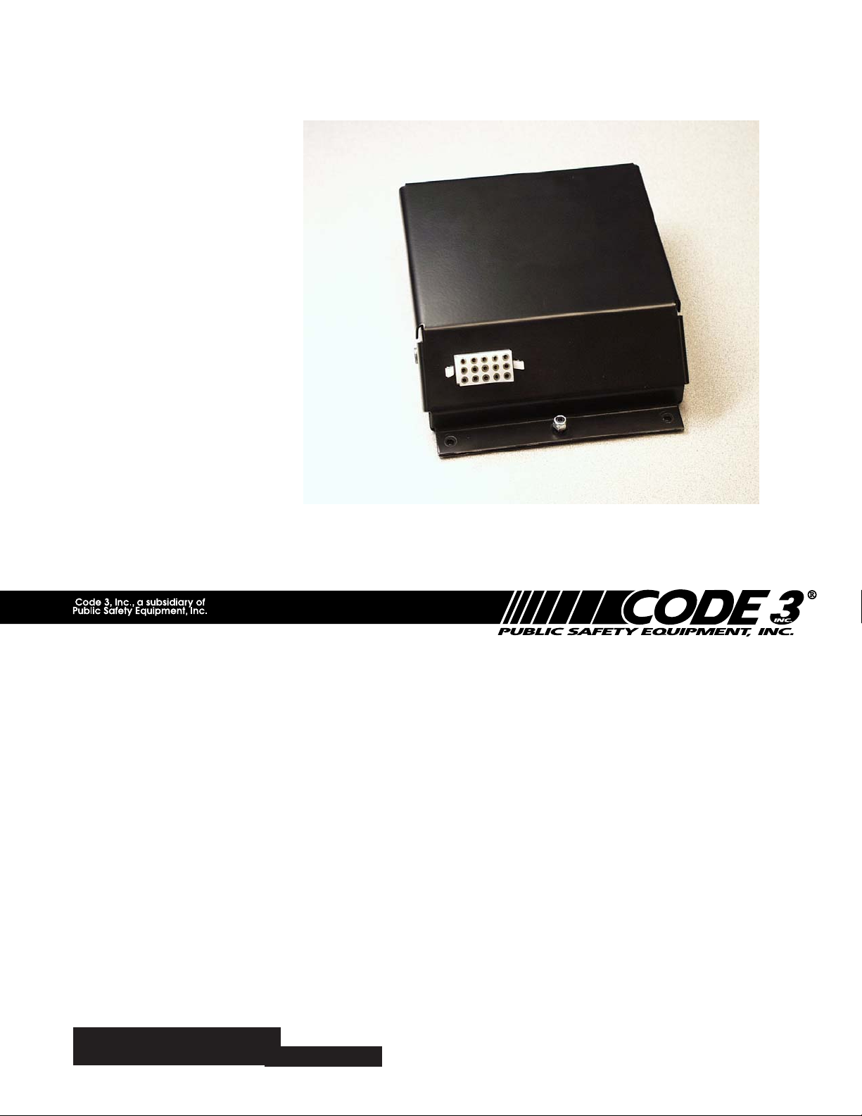
MODEL 3951
MOTORCYCLE SIREN
IMPORTANT:
MODEL 3951 SIREN
Contents:
Introduction ......................................................... 2
Standard Features .............................................. 2
Unpacking & Pre-Installation .............................. 3
Installation & Mounting ....................................... 3
Set-Up and Adjustment ...................................... 6
Operation ............................................................ 7
Specifications ..................................................... 8
Maintenance ....................................................... 8
Troubleshooting ............................................. 9-10
Parts List ........................................................... 11
Exploded View .................................................. 12
Notes ........................................................... 13-15
Warranty ........................................................... 16
Read all instructions and warnings before installing and using.
INSTALLER: This manual must be delivered to the end user of this equipment.
Page 3

Introduction
The Model 3951 siren has been designed to meet the special needs of motorcycle applications. This series
of sirens incorporates a rugged steel enclosure along with microprocessor based circuitry and MOSFET
technology. Advanced features such as Instant "ON", Scroll, and more, make the 3951 siren extremely
versatile.
Sirens are an integral part of an effective audio/visual emergency warning system. How-
!
WARNING!
ever, sirens are only short range secondary warning devices. The use of a siren does not
insure that all drivers can or will observe or react to an emergency warning signal, particularly at long distances or when either vehicle is traveling at a high rate of speed. Sirens
should only be used in a combination with effective warning lights and never relied upon as
a sole warning signal. Never take the right of way for granted. It is your responsibility to be
sure you can proceed safely before entering an intersection, driving against traffic, or
responding at a high rate of speed.
The effectiveness of this warning device is highly dependent upon correct mounting and
wiring. Read and follow the manufacturer’s instructions before installing or using this
device. The vehicle operator should check the equipment daily to insure that all features of
the device operate correctly.
To be effective, sirens must produce high sound levels that potentially can inflict hearing
damage. Installers should be warned to wear hearing protection, clear bystanders from the
area and not to operate the siren indoors during testing. Vehicle operators and occupants
should assess their exposure to siren noise and determine what steps, such as consultation
with professionals or use of hearing protection should be implemented to protect their
hearing.
This equipment is intended for use by authorized personnel only. It is the user’s responsibility to understand and obey all laws regarding emergency warning devices. The user
should check all applicable city, state and federal laws and regulations.
Public Safety Equipment, Inc., assumes no liability for any loss resulting from the use of this
warning device.
Proper installation is vital to the performance of the siren and the safe operation of the
emergency vehicle. It is important to recognize that the operator of the emergency vehicle
is under psychological and physiological stress caused by the emergency situation. The
siren system should be installed in such a manner as to: A) Not reduce the acoustical
performance of the system, B) Limit as much as practical the noise level in the passenger
compartment of the vehicle, C) Place the controls within convenient reach of the operator
so that he can operate the system without losing eye contact with the roadway.
Emergency warning devices often require high electrical voltages and/or currents. Properly
protect and use caution around live electrical connections. Grounding or shorting of electrical connections can cause high current arcing, which can cause personal injury and/or
severe vehicle damage, including fire.
PROPER INSTALLATION COMBINED WITH OPERATOR TRAINING IN THE PROPER
USE OF EMERGENCY WARNING DEVICES IS ESSENTIAL TO INSURE THE SAFETY
OF EMERGENCY PERSONNEL AND THE PUBLIC.
Standard Features
The Model 3951 siren is a highly integrated siren amplifier designed to be operated via user supplied control
switches and common microphone interface. The following features are standard on Model 3951 sirens:
Siren Tones - Industry standard Wail, Yelp, and HyperYelp tones.
AIR HORN Tone - Electronic AIR HORN sound.
Instant-On- There is no " ON/OFF " switch. Selecting any siren function, or pressing the Push To Talk (PTT)
switch on the user supplied common microphone interface will activate the siren in the appropriate mode,
assuming the siren is connected to a source of +12V and the vehicle's ignition switch is on.
2
2
Page 4

Scroll - A momentary positive signal applied to this input from a user supplied switch will cause to siren to
activate. The siren will scroll to the next tone each time the switch is tapped. Holding the scroll switch will
cause to siren to switch to Standby mode.
Wail - A continuous positive signal applied to this input from a user supplied switch will cause to siren to
activate in wail mode for as long as the switch remains in the on position.
Airhorn - A continuous positive signal applied to this input from a user supplied switch will cause to siren to
generate the Airhorn signal for as long as the switch remains in the on position.
Instant Public Address - Public Address override of all siren functions when the motorcycle Push-to-Talk
(PTT) key is pressed while the user supplied common microphone interface is set to PA mode.
Radio Rebroadcast - Broadcasts Two-way radio reception over siren speakers. These inputs are transformer
coupled to prevent loading of the radio.
InterClear® - This unique feature can be used to activate additional warning lights for 7 seconds, each time
the siren mode is changed using either the control switches or the vehicle horn ring, thus allowing an
additional level of warning in situations such as intersections without the operator having to take his hands off
the wheel or his eyes off the road.
Automatic Short Circuit Protection- The siren will sense a short circuit on the speaker terminals and
automatically go to standby until the fault is removed. Once the fault is removed the siren will return to normal
operation.
Unpacking & Pre-installation
After unpacking your 3951 series siren, carefully inspect the unit and associated parts for any damage that
may have been caused in transit. Report any damage to the carrier immediately.
Installation & Mounting
The 3951 series siren is designed to be mounted in the 2-way radio case or other weather protected area.
Ease of operation and convenience to the operator should be the prime consideration when mounting the siren
and controls.
All devices should be mounted in accordance with the manufacturer’s instructions and
securely fastened to vehicle elements of sufficient strength to withstand the forces applied to the
device. Ease of operation and convenience to the operator should be the prime consideration when
!
WARNING!
mounting the siren and controls. Adjust the mounting angle to allow maximum operator visibility.
Do not mount the Control Head Module in a location that will obstruct the drivers view. Mount the
microphone clip in a convenient location to allow the operator easy access. Devices should be
mounted only in locations that conform to their SAE identification code as described in SAE
Standard J1849. For example, electronics designed for interior mounting should not be placed
underhood, etc.
Controls should be placed within convenient reach* of the driver or if intended for two person
operation the driver and/or passenger. In some vehicles, multiple control switches and/or using
methods such as “horn ring transfer” which utilizes the vehicle horn switch to toggle between siren
tones may be necessary for convenient operation from two positions.
*Convenient reach is defined as the ability of the operator of the siren systems to manipulate
the controls from his normal driving/riding position without excessive movement away from
the seat back of loss of eve contact with the roadway.
3
Page 5

NOTE: Set-ups and adjustments will be made in subsequent steps, this will require
access to both the front and rear of the unit. Plan the installation and wiring
accordingly.
Connections (see Figure 1), motorcycle wiring harness.
Speaker - Connect to 100W ( 11 ohm ) speaker leads.
IGNITION - Connect (18 AWG wire) to the motorcycle's ignition switch so that +12VDC is applied to
this wire only when the ignition switch is in the ON position.
+12V - Connect (14 AWG wire) to a positive +12 volt DC source. It is recommended that the user
protect this wire with a 10 Amp fuse or circuit breaker located at the source.
Larger wires and tight connections will provide longer service life for components. For
high current wires it is highly recommended that terminal blocks or soldered connections be used
!
WARNING!
with shrink tubing to protect the connections. Do not use insulation displacement connectors (e.g.
3M® ) Scotchlock type connectors). Route wiring using grommets and sealant when passing
through compartment walls. Minimize the number of splices to reduce voltage drop. High ambient
temperatures (e.g. underhood) will significantly reduce the current carrying capacity of wires,
fuses, and circuit breakers. Use "SXL" type wire in engine compartment. All wiring should
conform to the minimum wire size and other recommendations of the manufacturer and be
protected from moving parts and hot surfaces. Looms, grommets, cable ties, and similar
installation hardware should be used to anchor and protect all wiring.
Fuses or circuit breakers should be located as close to the power takeoff points as possible and
properly sized to protect the wiring and devices. Particular attention should be paid to the location
and method of making electrical connections and splices to protect these points from corrosion
and loss of conductivity. Ground (Earth) terminations should only be made to substantial chassis
components, preferably directly to the vehicle battery.
The user should install a circuit breaker sized to approximately 125% of the maximum Amp
capacity in the supply line to protect against short circuits. For example, a 30 Amp circuit breaker
should carry a maximum of 24 Amps.
DO NOT USE 1/4" DIAMETER GLASS FUSES AS THEY ARE NOT SUITABLE FOR
CONTINUOUS DUTY IN SIZES ABOVE 15 AMPS. Circuit breakers are very sensitive to high
temperatures and will "false trip" when mounted in hot environments or operated close to their
capacity.
!
WARNING!
CONNECTION OF A 58 WATT SPEAKER TO THE SPKR TERMINAL WILL CAUSE THE
SPEAKER TO BURN OUT, AND WILL VOID THE SPEAKER WARRANTY!
The sound projecting opening should be pointed forward, parallel to the ground, and not obstructed
or muffled by structural components of the vehicle. Concealed or under-hood mounting in some
cases will result in a dramatic reduction in performance. To minimize this eduction, mount the
speaker so the sound emitted is projected directly forward and obstruction by vehicle components
such as hoses, brackets, grille, etc. is minimized.
Electromechanical sirens and electronic siren speakers should be mounted as far from the
occupants as possible using acoustically insulated compartments and isolation mountings to
minimize the transmission of sound into the vehicle. It may be helpful to mount the device on the
front bumper, engine cowl or fender; heavily insulate the passenger compartment; and operate the
siren only with the windows closed.
Each of these approaches may cause significant operational problems, including loss of siren
performance from road slush, increased likelihood of damage to the siren in minor collisions, and
the inability to hear the sirens on other emergency vehicles.
APPROPRIATE TRAINING OF VEHICLE OPERATORS IS RECOMMENDED TO ALERT THEM
TO THESE PROBLEMS AND MINIMIZE THE EFFECT OF THESE PROBLEMS DURING
OPERATIONS.
4
Page 6
- NEG (Ground) - Connect (14 AWG wire) to the negative terminal of the battery. This supplies
ground (earth) to the siren.
SCROLL- SCROLL switch input . Circuit is configured to accept positive signals only.
InterClear® - Connect to the device or circuit that is to be activated by the InterClear feature. The
InterClear circuit is internally current limited at 1 Amp. Should your requirements require higher
currents, use the InterClear Power Booster Kit (# INTBS), available from your Code 3® supplier.
AIRHORN - AIRHORN switch input . Circuit is configured to accept positive signals only.
RRB - RRB Audio Input. Connects to the two-way radio speaker.
WAIL - WAIL switch input . This switch should be a rocker type switch which maintains it's position
until switched OFF by the user. This circuit is configured to accept positive signals only.
RRB ENABLE - switch input . This switch should be a rocker type switch which maintains is position
until switched OFF by the user. Circuit is configured to accept positive signals only.
Microphone High - MIC HI signal from the user supplied, common microphone interface.
Microphone Low - MIC LO signal from the user supplied, common microphone interface.
PA PTT - PTT signal from the user supplied common microphone interface.
Set-Up and Adjustment
The only adjustments necessary for the 3951 series sirens are Maximum P.A. Adjustment (accessible from
the front of the unit), and Maximum RRB Adjustment (accessible from the rear of the unit). Refer to Figure 2
for the location of these adjustments. Make these adjustments prior to securing the unit .
MAXI MUM RRB AUDIO ADJUSTMENT
Code 3, Inc., a subsidiary of
Publ ic Safety Equi pment, I nc.
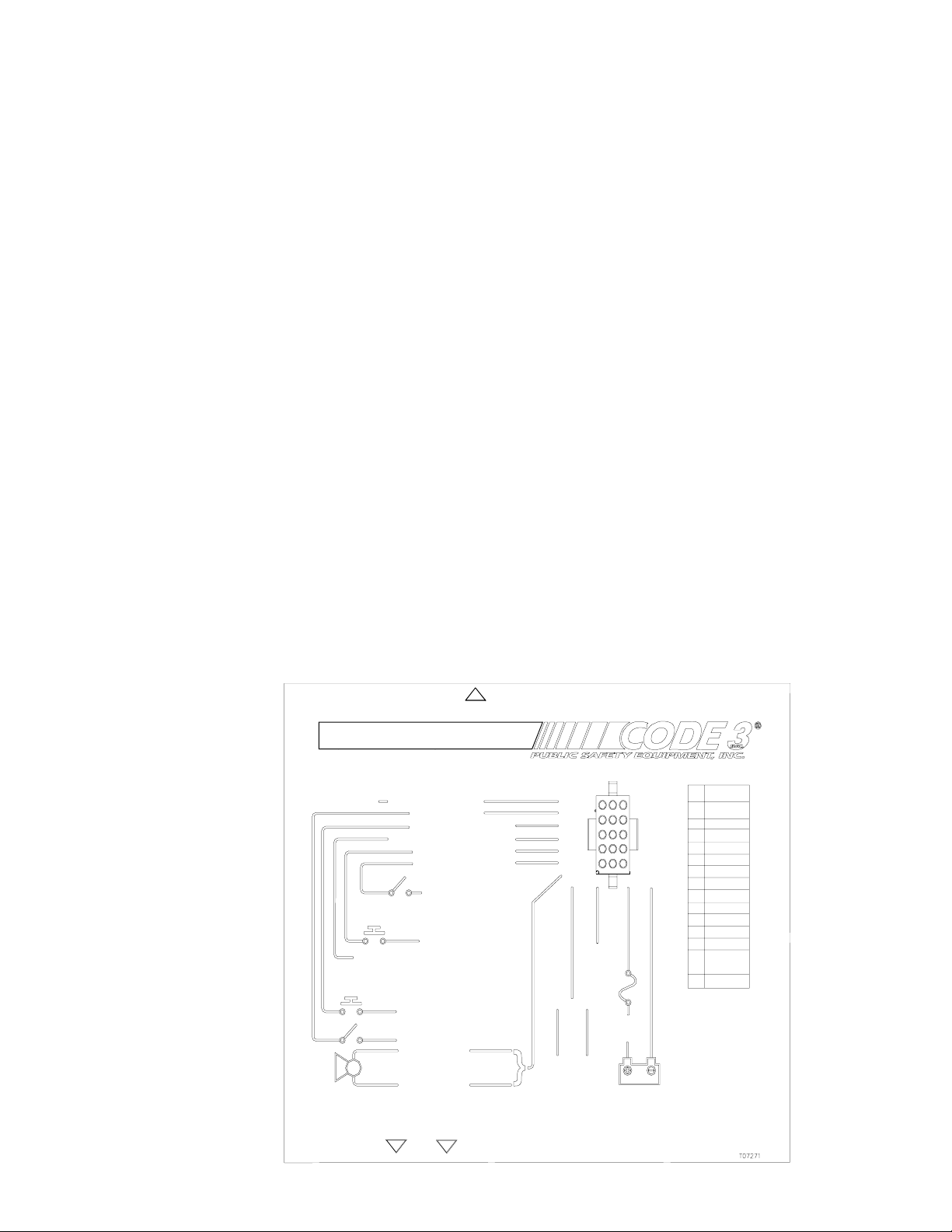
MODEL 3951 SIREN WIRING DIAGRAM
+12VDC
GROUND
SCROLL
RRB1
PA PTT
14AWG BLK,
GROUND
(EARTH)
PIN FUNCTI ON
1 SPK1
2 SPK2
3 IGNITION
4
5
6
7 INTERCLR
8 AIRHORN
9
10 RRB2
11 WAIL
12 RRB ENBL
13 MIC HI
14 MIC LO
15
Figure 1
USER INTERFACE
100W
SIREN
SPEAKER
PA MI C
WAI L I NPU T
AI RHORN INPUT
RRB SWITCH
+ 12VDC
+12VDC
SWITCH
14AWG
14AWG
SCROLL INPUT
RRB ENABLE
INTERCL EAR OUTPUT
AIRHORN SWI TCH
INTERCLEA R, 1A MAX
USE CODE 3 POWER BOOSTER KIT (P/N INTBS)
FOR MORE THAN 1A ON INTERCLEAR OUTPUT
SCROLL
+12VDC
WAILSWITCH
+12VDC
13-14-15
11
6
7
8
12
1-2
9-10
3
IGNITION
SWITCHED
+12VDC
10A*
FUSE
14AWGRED
RRB
18AWG
AUDIO INPUT FROM
2-WAY RADIO
2
1
456
78
10
11 1 2
13
14 15
+12VDC
3
9
45
*USER MUST SUPPLY EXTERNAL 10A FUSE IN +12VDC POWER WIRE
VOLUME CONTROL
MAXIMUM PA LEVEL ADJUSTMENT
5
Page 7
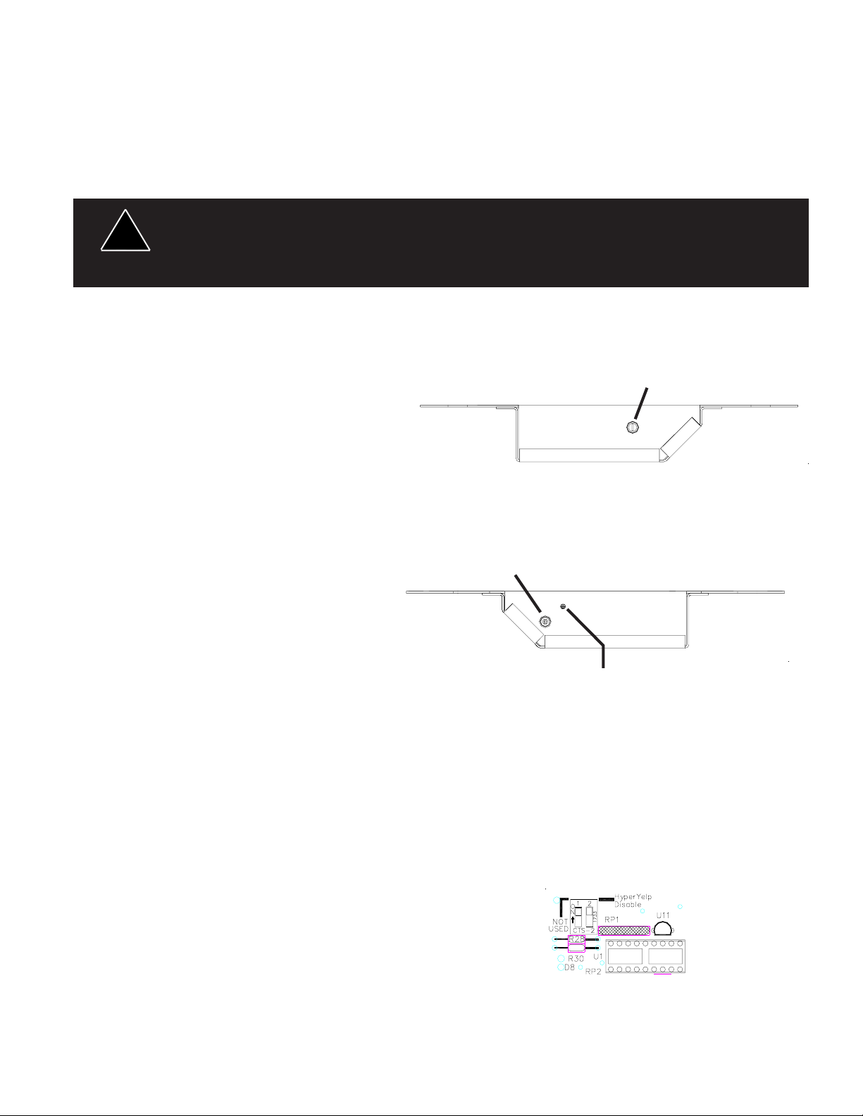
Audio Adjustments
Maximum Radio Rebroadcast (RRB) Adjustment - This trimmer (located on the rear of the siren) sets the
maximum level that the 2-way radio will reach with the front panel VOLUME control in the fully clockwise
position. To adjust properly, set the 2-way radio volume control to produce normal radio volume from the 2way radio speaker or headset. Set the RRB switch to the on position to enable the RRB function. Next set
the siren's front panel VOLUME control knob fully clockwise and adjust the rear panel RRB trimmer to produce
the desired volume from the siren speaker.
Any electronic device may create or be affected by electromagnetic interference. After
!
WARNING!
Maximum P.A. Volume Adjustment - This trimmer ( located on the front panel next to the volume control
knob) sets the maximum level that the P.A.
volume will reach with the front panel
VOLUME control in the fully clockwise
position. To adjust properly, set the front panel
volume control fully clockwise. While keying
the microphone hold the microphone close to
your lips and speak directly into it in a normal
voice and adjust the trimmer until the
maximum volume out of the speaker is
intelligible and produces no feedback. Set the
front panel volume control for the desired PA
volume and install all screws and fastners.
Configuration Switches
installation of any electronic device, operate all equipment simultaneously to insure
that operation is free of interference.
MAXIMUM RRB
Adjustment
Rear View
Volume
Control
Front View
HyperYelp Disable Switch - Switch DS1 is
shown in Figure 3. When switch 2 on DS1 is
switched to the ON position, the HyperYelp
tone is disabled. Switch 1 is not used.
MAXIMUM PA Adjustment
Figure 2 - Adjustments
Operation
SCROLL, Momentary Push-button Switch - Each time the SCROLL button is pressed it causes the siren to
scroll up one tone. Starting from the OFF mode, pressing the SCROLL button will cause the siren to start
producing the WAIL tone. Pressing the button again will cause the siren to switch to YELP mode. Pressing
the button again will cause the siren to switch to HyperYelp mode. Pressing the button a fourth time will cause
the siren to switch back to WAIL mode. This process may be repeated as often as desired.
WAIL, Latching Switch - Produces the Wail tone continuously while this switch is in the ON position.
Figure 3 -
Configuration
Switches
6
Page 8

AIR HORN, Momentary Push-button Switch - Produces the Air Horn tone. If the siren is active in any mode,
it reverts to that previous mode when the AIR HORN button is released.
RRB Switch - The RRB switch, is used to enable or disable the Radio Rebroadcast (RRB) function.
RRB is enabled, all other siren functions except PA are disabled.
When the switch is on, the 2-way radio audio connected to the RRB input wires is routed through the siren
amplifier to the siren speaker. The RRB volume from the siren speaker may be set by adjusting the 2-way
radio's volume control. Also refer to Maximum Radio Rebroadcast (RRB) Adjustment under the SET-UP AND
ADJUSTMENT section.
PUBLIC ADDRESS (PA) - The PA portion of the siren is activated each time the motorcycle Push-to-Talk
(PTT) button is pressed while the user supplied common microphone interface is set to PA mode. While the
PTT button is pressed, the PA function overrides any active siren tone and routes the PA audio through the
siren speaker. When the PTT button is released, the siren will automatically switch back to the siren tone (if
any) that was active when the button was pressed. Also refer to the Maximum P.A. Volume Adjustment
procedure under the SET-UP AND ADJUSTMENT section.
INTERCLEAR - The InterClear output provides a timed output from the siren which can be used to activate a
special warning light or function. Each time the siren mode is changed by any of the means previously
described the InterClear output switches on (+12VDC, 1A Max) for approximately eight (8) seconds. Turning
the siren off will also turn the InterClear output off. Use Code 3 power booster kit (p/n INTBS) for
applications requiring more than 1A on the InterClear output.
When
!
WARNING!
IMPORTANT WARNINGS TO USERS OF SIRENS: "Wail" and "Yelp" tones are in some
cases (such as in the state of California) the only recognized siren tones for calling for
the right of way. Ancillary tones such as "Air Horn", "Hi-Lo", "Hyperyelp", and "Hyperlo"
in some cases do not provide as high a sound pressure level. It is recommended that
these tones be used in a secondary mode to alert motorists to the presence of multiple
emergency vehicles or to momentarily shift from the primary tone as an indication of the
imminent presence of an emergency vehicle.
7
Page 9

Specifications
Siren Section
Input Voltage - 10 to 16 VDC, negative ground (earth).
(Note: Operation above 15 VDC for an extended period of time may result in speaker damage
Operating Current: 8A @ 13.6V with 11-ohm load ( 100W Spkr )
Standby Current: 12 mA
Cycle Rate: WAIL - 11 cycles/minute.
YELP - 200 cycles/minute.
Voltage Output ( approx. ) 65 V peak-to-peak
Audio Section
Audio Response: 3 dB down points - 500 to 3000 hz.
1000 hz. 0 dB Reference
Audio Distortion: 10% or less below clipping
Maintenance
Your Code 3® Model 3950 siren has been designed to provide trouble free service. In case of difficulty,
consult the Troubleshooting Guide located on pages 10 and 11 of this manual. Also check for shorted or open
wires. The primary cause of short circuits has been found to be wires passing through firewalls, roofs, etc. If
further difficulty persists, contact the factory for troubleshooting advice or return instructions. Public Safety
Equipment, Inc. maintains a complete parts inventory and service facility at the factory and will repair or
replace (at the factory's option) any unit found to be defective under normal use and in warranty. Any attempt
to service a unit in warranty, by anyone other than a factory authorized technician, without the express written
consent of the factory, will void the warranty. Units out of warranty can be repaired at the factory for a
nominal charge on either a flat rate or parts and labor basis. Contact the factory for details and return
instructions. Public Safety Equipment, Inc. is not liable for any incidental charges related to the repair or
replacement of a unit unless otherwise expressly agreed to in writing by the factory.
8
Page 10

TROUBLESHOOTING GUIDE
(Refer to Figure 1 - Wiring Diagram)
PROBLEM
NO SIREN OUTPUT.
10A FUSE BLOWS. A. AMPLIFIER POWER WIRES
NO OUTPUT FROM
SPEAKER, TONES
HEARD INSIDE
AMP. MODULE.
SIREN TONES
VOLUME TOO
LOW/GARBLED.
PROBABLE CAUSE
A. SHORTED SPEAKER OR SPEAKER
WIRES. SIREN IN OVER CURRENT
PROTECTION MODE.
REVERSED POLARITY
A. SPEAKER NOT CONNECTED/
OPEN OR SHORTED SPEAKER
WIRING
B. DEFECTIVE SPEAKER (NOTE:
SHORTED SPEAKER OR SPEAKER
WIRING WILL CAUSE SIREN TO
SHUT DOWN
A. LOW VOLTAGE TO SIREN
AMPLIFIER
B. HIGH RESISTANCE IN WIRING/
DEFECTIVE SPEAKER
REMEDY
A. CHECK
CONNECTIONS
A. CHECK POLARITY
A. CHECK SPEAKER
WIRING
B. DISCONNECT
SPEAKER, LISTEN AT
SIREN FOR TONES,
REPLACE SPEAKER
A. CHECK WIRING FOR
BAD CONNECTIONS/
CHECK VEHICLE
CHARGING SYSTEM
B. CHECK SPEAKER
WIRING/REPLACE
SPEAKER
HIGH RATE OF
SPEAKER FAILURE.
SIREN CONTINUES
UNTIL TONE RAMPS
DOWN AFTER MANUAL
BUTTON IS RELEASED.
INTERCLEAR WILL NOT
POWER AUXILIARY
DEVICES.
P.A. VOLUME LOW OR
NO P.A. AT ALL.
VOLUME CONTROL
FULLY CLOCKWISE.
A. HIGH VOLTAGE TO SIREN
B. 58 WATT SPEAKER CONNECTED
TO 100 WATT TAP. 58 WATT NOT
ALLOWED.
NORMAL OPERATION
A. THERE IS A SHORT IN THE
WIRING, OR THE LOAD IS GREATER
THAN 1 A.
A. DEFECTIVE MICROPHONE
B. MAXIMUM P.A. VOLUME
TRIMMER MISADJUSTED. SEE SETUP AND ADJUSTMENT SECTION.
A. CHECK VEHICLE
CHARGING SYSTEM
B. USE CORRECT
SPEAKER
A. CHECK FOR SHORTS.
INSTALL INTERCLEAR
BOOSTER KIT (PART
#INTBS)
A. REPLACE
MICROPHONE
B. REFER TO SET-UP
AND ADJUSTMENT
SECTION
9
Page 11

TROUBLESHOOTING GUIDE
(Refer to Figure 1 - Wiring Diagram)
PROBLEM
RRB VOLUME LOW, OR
NO RRB AT ALL.
VOLUME CONTROL
FULLY CLOCKWISE.
SIREN SOUNDS BY
ITSELF.
PA OPERATES BUT
SIREN WILL NOT RUN
SIREN RUNS PROPERLY
BUT SHUTS DOWN
WHILE RUNNING, THEN
STARTS RUNNING
AGAIN AFTER A FEW
MINUTES
PROBABLE CAUSE
A. MAXIMUM RADIO REBROADCAST
TRIMMER MIS-ADJUSTED
B. RRB WIRES NOT CONNECTED TO
TWO-WAY RADIO EXTERNAL
SPEAKER
A. REMOTE SWITCH (HORN RING)
WIRING TO REMOTE INPUT
SHORTING TO POSITIVE OR TO
GROUND (EARTH).
A. VEHICLE IN PARK; THE PARK
KILL FEATURE MUTES SIREN WHILE
VEHICLE IS IN PARK OR NEUTRAL.
B. RRB SWITCH IS ON.
A. VEHICLE CIRCUIT BREAKERS
NOT RATED PROPERLY, AND ARE
OVERHEATING, OR ARE NOT
FUNCTIONING PROPERLY
REMEDY
A. REFER TO SET-UP
AND ADJUSTMENT
SECTION
B. CHECK RRB
CONNECTIONS
A. CHECK WIRING FOR
ANY SHORTING.
A. PUT VEHICLE IN
GEAR.
B. TURN RRB SWITCH
OFF (LEFT).
A. REFER TO
SPECIFICATIONS
SECTION, PAGE 8.
USE A BREAKER WITH
1.25x THE AMPERAGE
RATING FOR THE
WATTAGE BEING USED.
10
Page 12

PARTS LIST (refer to Figure 4, Exploded View)
3951 Siren Parts List
Ref No. Description Part No. Qty.
1 E-Tray T07270 1
2 Insulator, Transistor T06363 2
3 Amplifier Assembly S71625 1
4 Screw 6-32 x .250 T01030 6
5 Bracket, Transformer S71629 1
6 Cover S71633 1
7 Nut 6-32 Locking Plated T11007 2
8 Nut 4-40 Locking Plated T03594 2
9 Label, Wiring T11008 1
10 Wiring Harness Assembly T11031 1
Wire, 14AWG Strand. Black T11025 1
NOTES
11
Page 13

3951 MOTORCYCLE SIREN
12
Figure 4, Exploded View
Page 14

Notes
13
Page 15

Notes
14
Page 16

Notes
15
Page 17

WARRANTY
Code 3, Inc.'s emergency devices are tested and found to be operational at the time of
manufacture. Provided they are installed and operated in accordance with manufacturer's
recommendations, Code 3, Inc. guarantees all parts and components except the lamps to a period
of 1 year (unless otherwise expressed) from the date of purchase or delivery, whichever is later.
Units demonstrated to be defective within the warranty period will be repaired or replaced at the
factory service center at no cost.
Use of lamp or other electrical load of a wattage higher than installed or recommended by the
factory, or use of inappropriate or inadequate wiring or circuit protection causes this warranty to
become void. Failure or destruction of the product resulting from abuse or unusual use and/or
accidents is not covered by this warranty. Code 3, Inc. shall in no way be liable for other damages
including consequential, indirect or special damages whether loss is due to negligence or breach
of warranty.
CODE 3, INC. MAKES NO OTHER EXPRESS OR IMPLIED WARRANTY INCLUDING,
WITHOUT LIMITATION, WARRANTIES OF FITNESS OR MERCHANTABILITY, WITH
RESPECT TO THIS PRODUCT.
PRODUCT RETURNS
If a product must be returned for repair or replacement*, please contact our factory to
obtain a Return Goods Authorization Number (RGA number) before you ship the product to
Code 3, Inc. Write the RGA number clearly on the package near the mailing label. Be sure you
use sufficient packing materials to avoid damage to the product being returned while in transit.
*Code 3, Inc. reserves the right to repair or replace at its discretion. Code 3, Inc. assumes no responsibility or liability for expenses incurred for
the removal and /or reinstallation of products requiring service and/or repair.; nor for the packaging, handling, and shipping: nor for the handling of
products return to sender after the service has been rendered.
NEED HELP? CALL OUR TECHNICAL ASSISTANCE HOTLINE - (314) 996-2800
St. Louis, Missouri 63114-2029—USA
10986 N. Warson Road
CODE 3, INC.
www.code3pse.com
Code 3 is a registered trademark of Code 3 Inc. a subsidiary of Public Safety Equipment, Inc.
Revision 1, 01/2006 - Instruction Book Part No. T07271
©2003-6 Code 3, Inc. Printed in USA
Page 18

INSTALLATION
& OPERATION
MANUAL
MODEL 3955
MOTORCYCLE SIREN
MODEL 3955
HARLEY DAVIDSON SIREN
Contents:
Introduction .......................................................... 2
Standard Features .............................................. 2
Unpacking & Pre-Installation................................ 3
Installation & Mounting ......................................... 3
Set-Up and Adjustment........................................ 4
Operation ............................................................ 4
Specifications...................................................... 5
Maintenance........................................................ 5
Troubleshooting................................................ 6-7
Warranty .............................................................. 8
IMPORTANT:
Read all instructions and warnings before installing and using.
INSTALLER: This manual must be delivered to the end user of this equipment.
Page 19

Introduction
The Model 3955 siren has been designed to meet the special needs of motorcycle applications. This siren
incorporates a rugged waterproof enclosure along with microprocessor based circuitry and MOSFET
technology.
Sirens are an integral part of an effective audio/visual emergency warning system. However,
!
WARNING!
sirens are only short range secondary warning devices. The use of a siren does not insure
that all drivers can or will observe or react to an emergency warning signal, particularly at
long distances or when either vehicle is traveling at a high rate of speed. Sirens should only
be used in a combination with effective warning lights and never relied upon as a sole warning
signal. Never take the right of way for granted. It is your responsibility to be sure you can
proceed safely before entering an intersection, driving against traffic, or responding at a high
rate of speed.
The effectiveness of this warning device is highly dependent upon correct mounting and
wiring. Read and follow the manufacturer’s instructions before installing or using this device.
The vehicle operator should check the equipment daily to insure that all features of the device
operate correctly.
To be effective, sirens must produce high sound levels that potentially can inflict hearing
damage. Installers should be warned to wear hearing protection, clear bystanders from the
area and not to operate the siren indoors during testing. Vehicle operators and occupants
should assess their exposure to siren noise and determine what steps, such as consultation
with professionals or use of hearing protection should be implemented to protect their
hearing.
This equipment is intended for use by authorized personnel only. It is the user’s responsibility to understand and obey all laws regarding emergency warning devices. The user should
check all applicable city, state and federal laws and regulations.
Public Safety Equipment, Inc., assumes no liability for any loss resulting from the use of this
warning device.
Proper installation is vital to the performance of the siren and the safe operation of the
emergency vehicle. It is important to recognize that the operator of the emergency vehicle is
under psychological and physiological stress caused by the emergency situation. The siren
system should be installed in such a manner as to: A) Not reduce the acoustical performance of the system, B) Limit as much as practical the noise level in the passenger compartment of the vehicle, C) Place the controls within convenient reach of the operator so that
he can operate the system without losing eye contact with the roadway.
Emergency warning devices often require high electrical voltages and/or currents. Properly
protect and use caution around live electrical connections. Grounding or shorting of electrical
connections can cause high current arcing, which can cause personal injury and/or severe
vehicle damage, including fire.
PROPER INSTALLATION COMBINED WITH OPERATOR TRAINING IN THE PROPER USE
OF EMERGENCY WARNING DEVICES IS ESSENTIAL TO INSURE THE SAFETY OF
EMERGENCY PERSONNEL AND THE PUBLIC.
Standard Features
The Model 3955 siren is a highly integrated siren amplifier designed to be operated via user supplied control
switches and common microphone interface. The following features are standard on Model 3959 sirens:
Siren Tones - Industry standard Wail and Yelp tones.
AIR HORN Tone - Electronic AIR HORN sound.
Instant-On- There is no " ON/OFF " switch. Selecting any siren function, or pressing the Push To Talk (PTT)
switch on the user supplied common microphone interface will activate the siren in the appropriate mode,
assuming the siren is connected to a source of +12V and the vehicle's ignition switch is on.
Wail - A continuous positive signal applied to this input from a user supplied switch will cause to siren to
activate in wail mode for as long as the switch remains in the on position.
Airhorn - A continuous positive signal applied to this input from a user supplied switch will cause to siren to
generate the Airhorn signal for as long as the switch remains in the on position.
Instant Public Address - Public Address override of all siren functions when the motorcycle Push-to-Talk (PTT)
key is pressed while the user supplied common microphone interface is set to PA mode.
Automatic Short Circuit Protection- The siren will sense a short circuit on the speaker terminals and
automatically go to standby until the fault is removed. Once the fault is removed the siren will return to normal
operation.
2
2
Page 20

Unpacking & Pre-installation
After unpacking your 3955 series siren, carefully inspect the unit and associated parts for any damage that may
have been caused in transit. Report any damage to the carrier immediately.
Installation & Mounting
The 3955 series siren is designed to be mounted to the optional equipment Harley Amplifier Mount, which can
be obtained from Harley Davidson. A weatherproof connector is provided for connection to the controller
harness provided with the Harley Davidson motorcycle.
Connections (see Figure 1), motorcycle wiring harness.
Speaker - Connect to 100W ( 11 ohm ) speaker leads.
+12V - Connect (14 AWG wire) to a positive +12 volt DC source. It is recommended that the user
protect this wire with a 10 Amp fuse or circuit breaker located at the source.
- NEG (Ground) - Connect (14 AWG wire) to the negative terminal of the battery. This supplies ground
(earth) to the siren.
AIRHORN - AIRHORN switch input . Circuit is configured to accept positive signals only.
WAIL - WAIL switch input . This switch should be a rocker type switch which maintains it's position
until switched OFF by the user. This circuit is configured to accept positive signals only.
Microphone High - MIC HI signal from the user supplied, common microphone interface.
Microphone Low - MIC LO signal from the user supplied, common microphone interface.
PA PTT - PTT signal from the user supplied common microphone interface.
CONNECTION OF A 58 WATT SPEAKER TO THE SPKR TERMINAL WILL CAUSE THE
SPEAKER TO BURN OUT, AND WILL VOID THE SPEAKER WARRANTY!
The sound projecting opening should be pointed forward, parallel to the ground, and not
obstructed or muffled by structural components of the vehicle. Concealed or under-hood mounting in
some cases will result in a dramatic reduction in performance. To minimize this reduction, mount the
speaker so the sound emitted is projected directly forward and obstruction by vehicle components such
as hoses, brackets, grille, etc. is minimized.
Electromechanical sirens and electronic siren speakers should be mounted as far from the
occupants as possible using acoustically insulated compartments and isolation mountings to minimize
the transmission of sound into the vehicle. It may be helpful to mount the device on the front bumper,
engine cowl or fender; heavily insulate the passenger compartment; and operate the siren only with the
windows closed.
Each of these approaches may cause significant operational problems, including loss of siren
performance from road slush, increased likelihood of damage to the siren in minor collisions, and the
inability to hear the sirens on other emergency vehicles.
APPROPRIATE TRAINING OF VEHICLE OPERATORS IS RECOMMENDED TO ALERT THEM
TO THESE PROBLEMS AND MINIMIZE THE EFFECT OF THESE PROBLEMS DURING
OPERATIONS.
WARNING!
WARNING!
!
All devices should be mounted in accordance with the manufacturer’s instructions
and securely fastened to vehicle elements of sufficient strength to withstand the forces
applied to the device. Ease of operation and convenience to the operator should be the
prime consideration when mounting the siren and controls. Adjust the mounting angle to
allow maximum operator visibility. Mount the microphone clip in a convenient location to
allow the operator easy access. Devices should be mounted only in locations that
conform to their SAE identification code as described in SAE Standard J1849.
Controls should be placed within convenient reach* of the driver. In some vehicles,
multiple control switches and/or using methods such as “horn ring transfer” which utilizes
the vehicle horn switch to toggle between siren tones may be necessary for convenient
operation from two positions.
*Convenient reach is defined as the ability of the operator of the siren systems to
manipulate the controls from his normal driving/riding position without excessive movement
away from the seat back of loss of eve contact with the roadway.
3
Page 21

Set-Up and Adjustment
The only adjustment necessary for the 3955 siren is the P.A. Volume Adjustment (accessible from the front of
the unit) Make this adjustment prior to securing the unit .
P.A. Volume Adjustment - This control is accessible by lifting the water resistant cover ( located on the end
of the siren opposite the connector) and sets the maximum level of the P.A. volume. While keying the
microphone hold the microphone close to your lips and speak directly into it in a normal voice and adjust the
control until the P.A. volume out of the speaker is at the desired level and produces no feedback. Be certain
that the spring loaded water resistant cover is fully closed after you have completed this adjustment.
Operation
WAIL, Switch - Produces the Wail tone continuously while this switch is in the ON position.
AIR HORN, Switch - Produces the Air Horn tone. If the siren is active in any mode, it reverts to that previous mode
when the AIR HORN button is released.
PUBLIC ADDRESS (PA) - The PA portion of the siren is activated each time the motorcycle Push-to-Talk (PTT)
button is pressed while the user supplied common microphone interface is set to PA mode. While the PTT
button is pressed, the PA function overrides any active siren tone and routes the PA audio through the siren
speaker. When the PTT button is released, the siren will automatically switch back to the siren tone (if any)
that was active when the button was pressed. Also refer to the Maximum P.A. Volume Adjustment procedure
under the SET-UP AND ADJUSTMENT section.
!
!
WARNING!
Any electronic device may create or be affected by electromagnetic interference.
After installation of any electronic device, operate all equipment simultaneously to
insure that operation is free of interference.
IMPORTANT WARNINGS TO USERS OF SIRENS: "Wail" and "Yelp" tones are in some
cases (such as in the state of California) the only recognized siren tones for calling for
the right of way. Ancillary tones such as "Air Horn", "Hi-Lo", "Hyperyelp", and "Hyperlo"
in some cases do not provide as high a sound pressure level. It is recommended that
these tones be used in a secondary mode to alert motorists to the presence of multiple
emergency vehicles or to momentarily shift from the primary tone as an indication of the
imminent presence of an emergency vehicle.
4
Page 22

D
Specifications
Input Voltage - 10 to 16 VDC, negative ground (earth).
(Note: Operation above 15 VDC for an extended period of time may result in speaker damage
Operating Current: 8A @ 13.6V with 11-ohm load ( 100W Spkr )
Standby Current: Ignition Switch input ON - Approx. 200 mA
Ignition switch input OFF- no stanby current
Cycle Rate: WAIL - 11 cycles/minute.
YELP - 200 cycles/minute.
Voltage Output ( approx. ) 65 V peak-to-peak
Audio Response: 3 dB down points - 500 to 3000 hz.
1000 hz. 0 dB Reference
Audio Distortion: 10% or less below clipping
Code 3,Inc., a subsidiary of
Public Safet y Eq uip m e nt, Inc .
USER INTERFACE
100W
SIREN
SPEAKER
MODEL 395 SIRENWIRING DIAGRAM
AIRHORN SWITCH
WA ILSWITCH
+12VDC
5
PA MIC
WAIL INPUT
AIRHORN INPUT
+12VDC
14AWG
14AW G
10A*
FUSE
14AW GRED
+12VDC
Figure 1
14AWGBLK,
GROUND
(EARTH)
PIN FUNCTION
A1 GROUND
A3 SPEAKER +
C1 +12V DC
C3 SPEAKER D1 AIR HORN
D2 PA PTT
E1 MIC LO
E2 MIC LO
F1 YELP
F2 WAIL
F3 MIC HI
ALL OTHER PINS NOT USE
Maintenance
Code 3® Model 3955 siren has been designed to provide trouble free service. In case of difficulty, consult the
Troubleshooting Guide located on pages 6 and 7 of this manual. Also check for shorted or open wires. The
primary cause of short circuits has been found to be wires passing through firewalls, roofs, etc. If further
difficulty persists, contact the factory for troubleshooting advice or return instructions. Public Safety Equipment,
Inc. maintains a complete parts inventory and service facility at the factory and will repair or replace (at the
factory's option) any unit found to be defective under normal use and in warranty.Any attempt to service a unit,
by anyone other than a factory authorized technician, without the express written consent of the factory, will void
the warranty. Units out of warranty can be repaired at the factory for a nominal charge on either a flat rate or
parts and labor basis. Contact the factory for details and return instructions. Public Safety Equipment is not
liable for any incidental charges related to the repair or replacement of a unit unless otherwise agreed to in
writing by the factory.
5
Page 23

PROBLEM
TROUBLESHOOTING GUIDE
(Refer to Figure 1 - Wiring Diagram)
PROBABLE CAUSE
REMEDY
NO SIREN OUTPUT.
10A FUSE BLOWS. A. AMPLIFIER POWER WIRES
NO OUTPUT FROM
SPEAKER, TONES
HEARD INSIDE
AMP. MODULE.
SIREN TONES
VOLUME TOO
LOW/GARBLED.
A. SHORTED SPEAKER OR
SPEAKER WIRES. SIREN IN OVER
CURRENT PROTECTION MODE.
REVERSED POLARITY
A. SPEAKER NOT CONNECTED/
OPEN OR SHORTED SPEAKER
WIRING
B. DEFECTIVE SPEAKER (NOTE:
SHORTED SPEAKER OR SPEAKER
WIRING WILL CAUSE SIREN TO
SHUT DOWN
A. LOW VOLTAGE TO SIREN
AMPLIFIER
B. HIGH RESISTANCE IN WIRING/
DEFECTIVE SPEAKER
A. CHECK
CONNECTIONS
A. CHECK POLARITY
A. CHECK SPEAKER
WIRING
B. DISCONNECT
SPEAKER, LISTEN AT
SIREN FOR TONES,
REPLACE SPEAKER
A. CHECK WIRING FOR
BAD CONNECTIONS/
CHECK VEHICLE
CHARGING SYSTEM
B. CHECK SPEAKER
WIRING/REPLACE
SPEAKER
HIGH RATE OF
SPEAKER FAILURE.
SIREN CONTINUES
UNTIL TONE RAMPS
DOWN AFTER MANUAL
BUTTON IS RELEASED.
P.A. VOLUME LOW OR
NO P.A. AT ALL.
VOLUME CONTROL
FULLY CLOCKWISE.
A. HIGH VOLTAGE TO SIREN
B. 58 WATT SPEAKER CONNECTED
TO 100 WATT TAP. 58 WATT NOT
ALLOWED.
NORMAL OPERATION
A. DEFECTIVE MICROPHONE
B. MAXIMUM P.A. VOLUME TRIMMER
MISADJUSTED. SEE SET-UP AND
ADJUSTMENT SECTION.
A. CHECK VEHICLE
CHARGING SYSTEM
B. USE CORRECT
SPEAKER
A. REPLACE
MICROPHONE
B. REFER TO SET-UP
AND ADJUSTMENT
SECTION
6
Page 24

TROUBLESHOOTING GUIDE
(Refer to Figure 1 - Wiring Diagram)
PROBLEM
SIREN SOUNDS BY
ITSELF.
SIREN RUNS
PROPERLY BUT SHUTS
DOWN WHILE
RUNNING, THEN
STARTS RUNNING
AGAIN AFTER A FEW
MINUTES
current wires it is highly recommended that terminal blocks or soldered connections be used with shrink
tubing to protect the connections. Do not use insulation displacement connectors (e.g. 3M® )
!
WARNING!
Scotchlock type connectors). Route wiring using grommets and sealant when passing through
compartment walls. Minimize the number of splices to reduce voltage drop. High ambient temperatures
(e.g. underhood) will significantly reduce the current carrying capacity of wires, fuses, and circuit
breakers. Use "SXL" type wire in engine compartment. All wiring should conform to the minimum wire
size and other recommendations of the manufacturer and be protected from moving parts and hot
surfaces. Looms, grommets, cable ties, and similar installation hardware should be used to anchor and
protect all wiring.
properly sized to protect the wiring and devices. Particular attention should be paid to the location and
method of making electrical connections and splices to protect these points from corrosion and loss of
conductivity. Ground (Earth) terminations should only be made to substantial chassis components,
preferably directly to the vehicle battery.
capacity in the supply line to protect against short circuits. For example, a 30 Amp circuit breaker
should carry a maximum of 24 Amps.
CONTINUOUS DUTY IN SIZES ABOVE 15 AMPS. Circuit breakers are very sensitive to high
temperatures and will "false trip" when mounted in hot environments or operated close to their capacity.
PROBABLE CAUSE
A. REMOTE SWITCH (HORN RING)
WIRING TO REMOTE INPUT
SHORTING TO POSITIVE OR TO
GROUND (EARTH).
A. VEHICLE CIRCUIT BREAKERS NOT
RATED PROPERLY, AND ARE
OVERHEATING, OR ARE NOT
FUNCTIONING PROPERLY
Larger wires and tight connections will provide longer service life for components. For high
Fuses or circuit breakers should be located as close to the power takeoff points as possible and
The user should install a circuit breaker sized to approximately 125% of the maximum Amp
DO NOT USE 1/4" DIAMETER GLASS FUSES AS THEY ARE NOT SUITABLE FOR
REMEDY
A. CHECK WIRING
FOR ANY SHORTING.
A. REFER TO
SPECIFICATIONS
SECTION, PAGE 8.
USE A BREAKER
WITH 1.25x THE
AMPERAGE RATING
FOR THE WATTAGE
BEING USED.
7
Page 25

WARRANTY
Code 3, Inc.'s emergency devices are tested and found to be operational at the time of
manufacture. Provided they are installed and operated in accordance with manufacturer's
recommendations, Code 3, Inc. guarantees all parts and components except the lamps to a period
of 1 year (unless otherwise expressed) from the date of purchase or delivery, whichever is later. Units
demonstrated to be defective within the warranty period will be repaired or replaced at the factory
service center at no cost.
Use of lamp or other electrical load of a wattage higher than installed or recommended by the
factory, or use of inappropriate or inadequate wiring or circuit protection causes this warranty to
become void. Failure or destruction of the product resulting from abuse or unusual use and/or
accidents is not covered by this warranty. Code 3, Inc. shall in no way be liable for other damages
including consequential, indirect or special damages whether loss is due to negligence or breach of
warranty.
CODE 3, INC. MAKES NO OTHER EXPRESS OR IMPLIED WARRANTY INCLUDING,
WITHOUT LIMITATION, WARRANTIES OF FITNESS OR MERCHANTABILITY, WITH RESPECT TO THIS PRODUCT.
PRODUCT RETURNS
If a product must be returned for repair or replacement*, please contact our factory to obtain
a Return Goods Authorization Number (RGA number) before you ship the product to Code 3, Inc.
Write the RGA number clearly on the package near the mailing label. Be sure you use sufficient
packing materials to avoid damage to the product being returned while in transit.
*Code 3, Inc. reserves the right to repair or replace at its discretion. Code 3, Inc. assumes no responsibility or liability for expenses incurred for the
removal and /or reinstallation of products requiring service and/or repair.; nor for the packaging, handling, and shipping: nor for the handling of products return to
sender after the service has been rendered.
NEED HELP? CALL OUR TECHNICAL ASSISTANCE HOTLINE (314) 996-2800
St. Louis, Missouri 63114-2029—USA
10986 N. Warson Road
www.code3pse.com
CODE 3, INC.
Code 3 is a registered trademark of Code 3, Inc. a subsidiary of Public Safety Equipment, Inc.
Revision 0, 02/2006 - Instruction Book Part No. T13727
©2003-6 Code 3, Inc. Printed in USA
 Loading...