

Page 1

INSTALLATION MANUAL
Read all instructions and warnings before installing and using.
INSTALLER:
This manual must be delivered to the end user of thi
s equipment.
IMPORTANT:
Introduction .................................................................................................................................................. 2
Product Features ......................................................................................................................................... 2
Specifications .............................................................................................................................................. 2
General Harnessing Instructions ............................................................................................................... 5
Control Harness Connections .................................................................................................................... 6
Power Harness Connections ...................................................................................................................... 8
Final Harness Connections ........................................................................................................................ 8
3x5 and XT-3 Installation Into Stainless Steel Enclosure ....................................................................... 10
Overhead Lighting Installation (ex. DuoBeams or Lightbars) ............................................................... 15
Additional Lighting Installation (ex. Smart 3x5, Arch Beacon, etc.) ...................................................... 15
Flash Patterns ............................................................................................................................................ 16
Replacement Parts .................................................................................................................................... 17
Notes: ......................................................................................................................................................... 18
1
Page 2

Product Patents Apply for the Matrix System
!
WARNING!
For U.S. Patent Nos. See https://secure.code3pse.com/patents/
Introduction
The Matrix System is designed to be mounted on a dump truck and can control the entire vehicle warning
lighting. It can flash synchronously with the programmability of the Matrix System Central Controller (CC).
The system can also Dim, Gang Shutoff, and Sync the warning lights powered from the CC. The Matrix
System controls your lights to match your situational needs by allowing the end user to change flash rates
(double, triple, quad-pop, etc.) as well as flash sequences (front-back, corner-corner, rotate-left-right, etc.)
Product Features
Contents
• Central Controller in control box with internal junctions.
• Harnessing for all power, control, and lighting in the system.
• 3x5 Light Heads including Split-Warning, Reverse, STT (Stop-Turn-Tail)
• Dimming capability for warning lights powered from the CC.
• Synchronous capability for all lighting equipment.
Specifications
• Control Box Dimensions: 8.75 x 5.25 x 3.30 (L x W x H) (inches)
• Control Box Weight: 1.5 lbs.
• 12 Volts
• 5 Year System Warranty
The use of this or any warning device does not ensure that all drivers can or will observe or react to an emergency warning signal.
Never take the right-of-way for granted. It is your responsibility to be sure you can proceed safely before entering an intersection,
driving against traffic, responding at a high rate of speed, or walking on or around traffic lanes. The effectiveness of this warning
device is highly dependent upon correct mounting and wiring. Read and follow the manufacturer’s instructions before installing or
using this device. The vehicle operator should insure daily that all features of the device operate correctly. In use, the vehicle
operator should insure the projection of the warning signal is not blocked by vehicle components (i.e.: open trunks or compartment
doors), people, vehicles, or other obstructions. This equipment is intended for use by authorized personnel only. It is the user’s
responsibility to understand and obey all laws regarding emergency warning devices. The user should check all applicable city,
state and federal laws and regulations. Code 3, Inc., assumes no liability for any loss resulting from the use of this warning device.
Proper installation is vital to the performance of this warning device and the safe operation of the emergency vehicle. It is
important to recognize that the operator of the emergency vehicle is under psychological and physiological stress caused by the
emergency situation. The warning device should be installed in such a manner as to: A) Not reduce the output performance of the
system, B) Place the controls within convenient reach of the operator so that he can operate the system without losing eye
contact with the roadway. Emergency warning devices often require high electrical voltages and/or currents. Properly protect and
use caution around live electrical connections. Grounding or shorting of electrical connections can cause high current arcing,
which can cause personal injury and/or severe vehicle damage, including fire. Driver and/or passenger air bags (SRS) will affect
the way equipment should be mounted. This device should be mounted by permanent installation and within the zones specified
by the vehicle manufacturer, if any. Any device mounted in the deployment area of an air bag will damage or reduce the
effectiveness of the air bag and may damage or dislodge the device. Installer must be sure that this device, its mounting hardware
and electrical supply wiring does not interfere with the air bag or the SRS wiring or sensors. Mounting the unit inside the vehicle
by a method other than permanent installation is not recommended as unit may become dislodged during swerving, sudden
braking or collision. Failure to follow instructions can result in personal injury. PROPER INSTALLATION COMBINED WITH
OPERATOR TRAINING IN THE PROPER USE OF EMERGENCY WARNING DEVICES IS ESSENTIAL TO INSURE THE
SAFETY OF EMERGENCY PERSONNEL AND THE PUBLIC.
2
Page 3

General Wiring
Matrix System Wiring
• Read through the wiring instructions for the Matrix System prior to the installation and become fully
familiar with it to be sure all of the connections will be made as needed for correct system operation. If
there are any questions or problems call our Technical Assistance HOTLINE - (314) 996-2800.
• Verify before final connections are made that Front Output wires are connected to front outputs and Rear
Output wires are connected to rear outputs before crimping the connections.
• Verify that the Front and Rear Output Harness Plugs are in their correct locations If they have been
unplugged they can be switched by accident!
• The majority of the wire colors from the Matrix System Box Front and Rear Output wires to the Front
Device Outputs (Lightbars, Beacons, DuoBeams) and Rear Device Outputs (Dual Color and Single Color
3x5 and XT-3s) match up color to color. Some wire color shades may vary slightly.
• The main power and ground wires should be connected directly to the vehicle's battery and not to an
auxiliary vehicle connection and must be fused properly. See wiring instructions for the Matrix System.
General Wiring Best Practices
• Larger wires and tight connections will provide longer service life for components. Follow the AWG Table
on the page 5 for proper wire gauges based on length of wire run.
• For high current wires it is highly recommended that terminal blocks or soldered connections be used with
heat shrink tubing to protect the connections.
• Do not use insulation displacement connectors (e.g. 3M® Scotchlock type connectors).
• Route wiring using grommets and sealant when passing through compartment walls.
• High ambient temperatures (e.g. under hood) will significantly reduce the current carrying capacity of
wires, fuses, and circuit breakers. Use "SXL" type wire in engine compartment.
• All wiring should conform to the minimum wire size and other recommendations of the wire manufacturer
and be protected from moving parts and hot surfaces.
• Looms, grommets, cable ties, and similar installation hardware should be used to anchor and protect all
wiring.
• Fuses or circuit breakers should be located as close to the power takeoff points as possible and properly
sized to protect the wiring and devices
• The installer should install a fuse sized to approximately 125% of the maximum Amp capacity in the
supply line to protect against short circuits. For example, a 30 Amp fuse should carry a maximum of 24
Amps.
• DO NOT USE 1/4" DIAMETER GLASS FUSES AS THEY ARE NOT SUITABLE FOR CONTINUOUS
DUTY IN SIZES ABOVE 15 AMPS!
• Circuit breakers are very sensitive to high temperatures and will "false trip: when mounted in hot
environments or operated close to their capacity.
Ground Connections
• Ground terminations should be made to substantial chassis components, preferably directly to the vehicle
battery. Some OEM provided ground points are not sufficient to provide a proper ground. If in doubt, check
to verify ground with a multimeter.
3
Page 4

General Wiring (continued)
Any electronic devices may
create or be affected by electromagnetic interference. After installation of any electronic device
!
WARNING!
!
WARNING!
• If Chassis Ground must be used, connection points should be clean and have paint or coatings removed
to insure a good tight ground connection. The gauge of the grounding wire must match the AWG Table
shown on page 5.
• Avoid stacking multiple ground connections to one ground source.
• Verify that hardware, screws, bolts, washers, etc. will provide a sufficient ground connection.
Splicing Connections
• Use the correct wire stripper to be sure all strands of the wires remain intact and will provide sufficient
electrical current capacity.
• Do not under strip or over strip the wire as it could prevent proper connections or leave bare wiring
exposed for potential short circuits.
• Use appropriate crimping plies to insure good connections.
• Always use properly sized connectors/terminals appropriate to the wire gauge being used (Butt Splices,
Fork Terminals, Ring Terminals, & etc.).
• Use wire of sufficient gage to provide sufficient electrical current capacity.
• Minimize the number of splices where ever possible to reduce voltage drop.
• Particular attention should be paid to the location and method of making electrical connections and splices
to protect these points from corrosion and loss of conductivity (Wire Loom, Heat Shrink Tubing, or Sealed
Connectors may be necessary in wet or hot environments).
RFI/EMI Considerations
• Do not locate the Matrix System Box close to an antenna or other RFI/EMI emitting device.
• Do not route cables or wires from a Matrix System within 18 inches of an antenna, antenna cable, radar
unit, radio amplifier, or other RFI/EMI emitting device.
Utilizing non-factory supplied screws and/or mounting brackets and/or the improper
number of screws may result in loss of warranty coverage on the equipment.
operate all equipment simultaneously to insure that operation is free of interference. Never power emergency warning equipment
from the same circuit or share the same grounding circuit with radio communication equipment. All devices should be mounted in
accordance with the manufacturer's instructions and securely fastened to vehicle elements of sufficient strength to withstand the
forces applied to the device.
4
Page 5
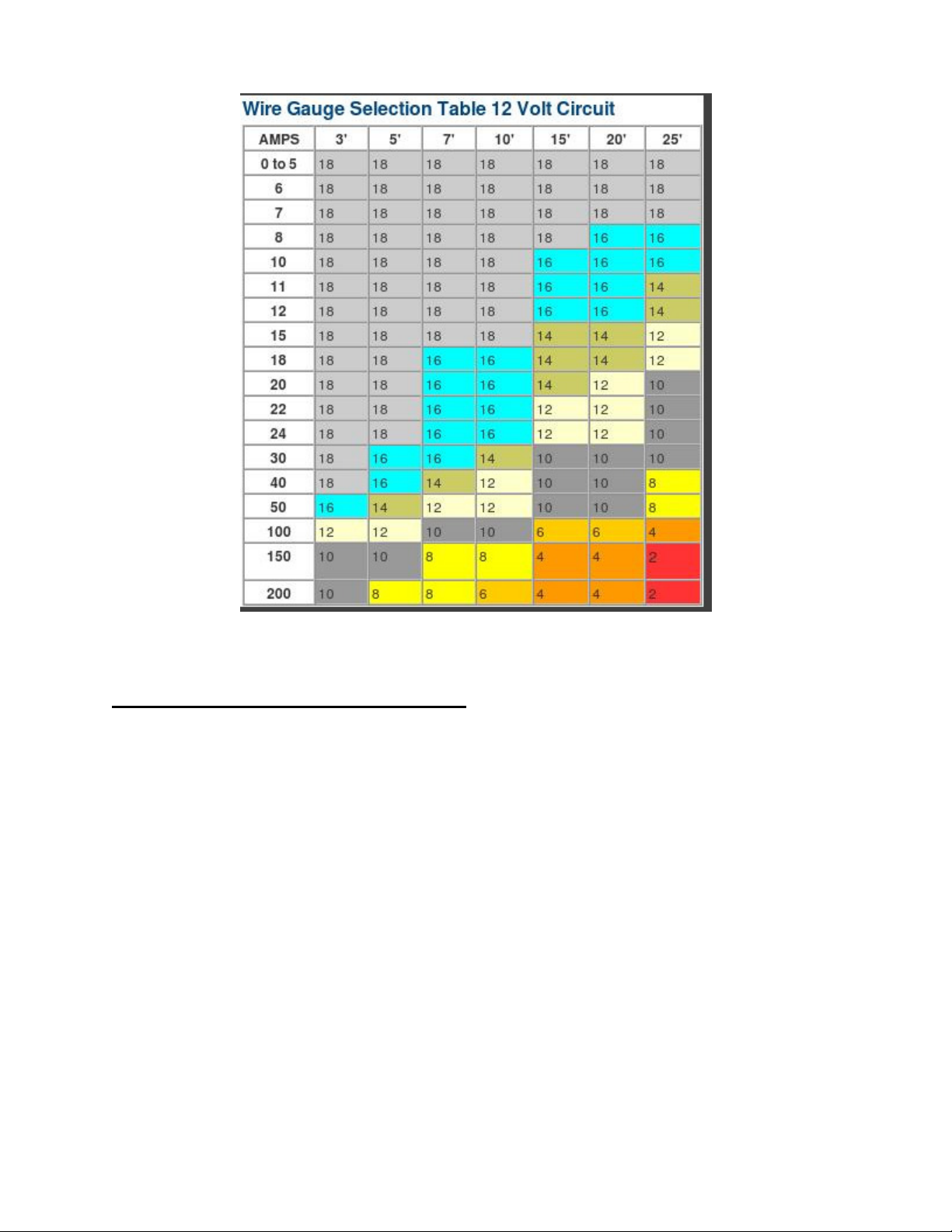
Wire Gauge Selection
General Harnessing Instructions
Once all the products in the Matrix System have been chosen and located in the vehicle, harnessing
supplied with the lights can be routed through the vehicle. It is best to route from the various lights back to
the Matrix System CC. This allows the harnessing to be cut to fit. Puncture holes in the break-thru plugs
with the wires from the lighting of the vehicle. Strip back the protective shield around the wires to expose
the individual wires inside. Once inside the Matrix System CC, quick connects (supplied) can be added to
each wire. Once all quick connects are properly crimped to the wires, attach either directly to the CC or to
the junctions in the CC box as needed.
5
Page 6
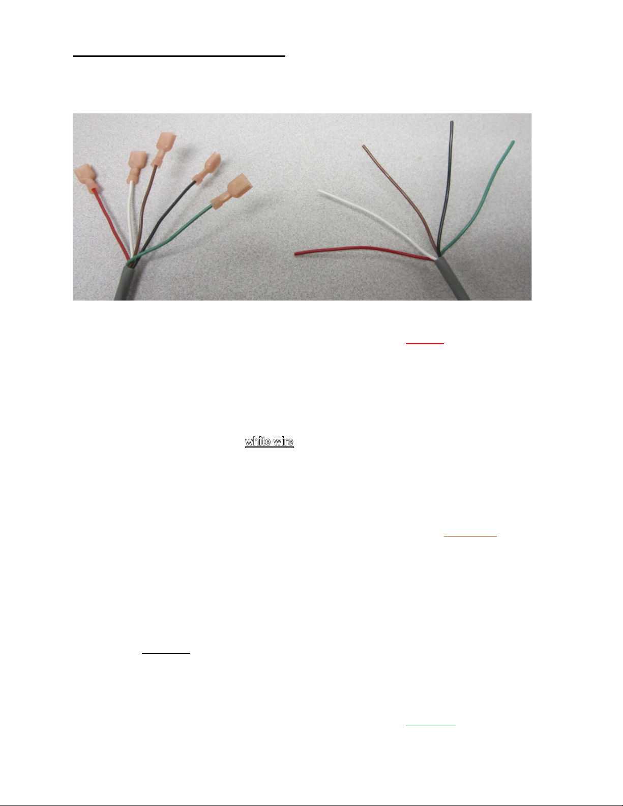
Control Harness Connections
Below is a picture of the control wire. This should be already connected to the Matrix System Central
Controller inside the large gray enclosure when received in the shipping container. A description of each
control and how it should be connected to the vehicle’s control switches is explained in the following
sections.
Main Lighting Selection
This turns on and off the exterior vehicle lighting from the switch box of the vehicle. The switch must be
connected to +12VDC so that when switched on it supplies +12VDC to the red wire of the control cable for
the Matrix System CC.
Dim Functionality
Dim will dim all outputs that are currently being activated by the Matrix System CC to 25%. Dim will not
affect units that are sync’d with the Matrix System CC unless the units have their own dimming wire that is
also tied to the dimming switch of the vehicle. The switch must be connected to +12VDC so that when
switched on it supplies +12VDC to the of the control cable for the Matrix System CC.
Flash Rate Selection
Flash Rate selection will increase to the next flash rate (single flash, triple flash, quad-pop flash, etc.) when
the Flash Rate wire is held to +12VDC for ~1 to 2 seconds. When held for 2 to 4 seconds it will decrease to
the previous flash rate. When held for longer than 4 seconds it resets to the default flash rate. The switch
must be connected to +12VDC so that when switched on it supplies +12VDC to the brown wire of the
control cable for the Matrix System CC.
Flash Sequence Selection
Flash Sequence selection will increase to the next flash sequence (front-back, corner-corner, rotate-leftright, etc.) when the Flash Sequence wire is held to +12VDC for ~1 to 2 seconds. When held for 2 to 4
seconds it will decrease to the previous flash sequence. When held for longer than 4 seconds it resets to
the default flash sequence. The switch must be connected to +12VDC so that when switched on it supplies
+12VDC to the black wire of the control cable for the Matrix System CC.
Gang Shutoff Selection
Gang Shutoff allows selected lighting on the vehicle to be turned off when traveling in a gang of vehicles.
This makes it easier for the drivers of the trailing vehicles to stay focused on the road. The switch must be
connected to +12VDC so that when switched on it supplies +12VDC to the green wire of the control cable
for the Matrix System CC.
6
Page 7

Control Harness Connections (continued)
Below is a picture of the control wires properly connected to the Matrix System Central Controller.
Green
Red
Brown
Black
7
Page 8

Power Harness Connections
Below is a picture of the power wire. This should be already connected to the Matrix System Central
Controller inside the large gray enclosure.
Power Wire
The +12VDC of the vehicle should be supplied through the red wire.
Ground Wire
The ground of the vehicle should be supplied through the black wire.
Below is a picture of the power wire connected properly to the Matrix System Central Controller.
Black Red
8
Page 9

Final Harness Connections
Below is a picture of how the product will arrive. The only connections remaining will be for the customer to
install the lights on the vehicle and run the harnesses back to the Matrix System Central Control box shown
below.
Although this unit is water resistant, it is not water proof and therefore SHOULD NOT be mounted on the
exterior of the vehicle!
Mount the Matrix System CC Box using two customer supplied screws to the interior of the vehicle. Note:
Below is an example of how to run the wire through the bushing. It is easiest to push through before
stripping back the sleeve or adding the quick connects. Once through the bushing, the sleeve can be
stripped and quick connects can be added. Strip jacket enough to allow plenty of room for the wires to
move about inside the Matrix CC box but leave enough of the jacket so that it still covers the wires for about
an inch after entering the box. Harnesses should not hinder opening the lid of the box.
9
Page 10

3x5 and XT-3 Installation Into Stainless Steel Enclosure
Stainless steel enclosures are available in single, double, and triple stack (see page 14). Mount XT-3 lights
if needed to the sides of enclosures. One enclosure for single, double, or triple stack can be used for side
mounted lights or solid sheet metal. Simply turn enclosure upside down to turn the hole to the inside of the
vehicle. The enclosures are symmetrical except for that hole. Note that the enclosures have a slight angle
on the top and bottom. This is to assist in drainage and avoid water build up in the enclosures.
The harness for the 3x5 and XT-3 should both be routed from the stainless steel enclosure through the
vehicle and into the cab. It is advisable to leave some extra cable at the Matrix System Central Controller
box for future installations.
Feed Harnesses for 3x5 and XT-3 from the back of the vehicle to the Matrix System Central
Controller
1. Weld stainless steel enclosure into the preferred location on the vehicle.
2. Attach fitting to conduit as shown below.
a. Twist white plastic insert into conduit.
b. Fit insert into fitting on the left.
c. Screw fitting on the right tight to fitting on the left.
10
Page 11

3. Attach conduit and fitting through hole in the rear of the stainless steel enclosure and secure with
nut.
Make sure conduit and fitting are installed in the hole on the back side of the stainless steel enclosure to
protect the harnesses from rubbing on the enclosure during normal use.
4. Feed the blunt cut end of harnesses through the conduit and fitting.
5. Continue feeding through the vehicle and into the cab.
6. Cut the cable to length long enough to make all connections inside the Matrix System Central
Controller box.
Attaching Harnesses for 3x5 and XT-3 to the Matrix System Central Controller
1. Push the harness through the black bushing on the box. It is easiest to push through before
stripping back the sleeve or adding the quick connects.
2. Pull in plenty of the harness to allow for running wires to their final destination.
3. Once through the bushing, the sleeve can be stripped and quick connects can be added. Strip
jacket enough to allow plenty of room for the wires to move about inside the Matrix CC box but
leave enough of the jacket so that it still covers the wires for about an inch after entering the box.
Harnesses should not hinder opening the lid of the box.
4. Strip individual wires to prepare them for crimping.
5. Crimp the quick connects onto each wire.
6. Attach each quick connect to its proper location inside the Central Controller box.
11
Page 12

Attaching 3x5 and XT-3 to the Harness
1. Install the XT-3 using the supplied brackets to match the stainless steel enclosure.
2. Install black adapter plate for mounting the 3x5.
3. Attach the XT-3 connector to the XT-3 harness previously fed through the vehicle.
12
Page 13

4. Attach the 3x5 connector to the 3x5 harness previously fed through the vehicle.
5. Set 3x5 Lens, PCB, and Heat Sink onto black adapter plate.
13
Page 14

6. Put four sheet metal screws (#6) through the chosen lens, through the heat sink, and into the black
adapter plate.
7. Repeat step 3 through 5 for STT and/or Reverse 3x5s as required.
Grommets are available for mounting all 3x5 lighting
to cutouts in the body of the vehicle. Replace sheet
metal screws with four #8 machine screws supplied
with grommets.
Bezels are also available for mounting directly
without having to cut a large hole for the grommet.
Single, double, and triple stack enclosures are
available for new installations if preferred.
14
Page 15

Overhead Lighting Installation
Overhead lighting of the Matrix System has multiple choices. This includes various lightbars, regular
beacons, Arch beacons, and even DuoBeams. Beacons will need to attach their sync wire to the sync wire
inside the Matrix System CC box. In addition, those beacons must be powered from the same switched
power supply of the vehicle so that the lights turn on when the Matrix System CC powers its lights. Matrix
System Lightbars and DuoBeams can be run directly from the Matrix System CC requiring no additional
sync wires.
1. Attach chosen overhead lighting to vehicle per instructions supplied with overhead lighting.
2. Attach appropriate harness to overhead lighting.
3. Feed overhead lighting harness through the vehicle to the Matrix System Central Controller box.
4. Push the harness through the black bushing on the box.
5. Pull in plenty of the harness to allow for running wires to their final destination.
6. Strip plenty of the harness away but leave enough to keep from pulling back through the bushing.
7. Strip individual wires to prepare them for crimping.
8. Crimp the quick connects onto each wire.
9. Attach each quick connect to its proper location inside the Central Controller box. (OH is
abbreviation of OverHead. Red wires attach to OH1-OH4. Black wires attach to OUTPUT
GROUND)
(ex. DuoBeams or Lightbars)
15
Page 16

Additional Lighting Installation
If a smart light head is to be sync’d with the system, power, ground, and sync wires are all that are needed.
1. Attach power wires through power switch for vehicle lights.
2. Attach sync wire to sync connection in Matrix System Central Controller box.
(ex. Smart 3x5, Arch Beacon, etc.)
Flash Patterns
In the Matrix System Central Controller, the flash patterns are split into two sections: rate & sequence. A
flash rate example would be Double Flash 75, Quad Flash 150, Single Flash 250, etc. Once the rate is set,
the sequence can be chosen. A flash sequence example would be Front/Back Lights, Driver/Passenger
Lights, Opposite Corners Lights, etc. Below is the order in which they can be selected when programming
the unit:
Flash Rates
1. Single Flash 75
2. Double Flash 75
3. Triple Flash 75
4. Quad Flash 75
5. Five Flash 75
6. Single Flash 150
7. Double Flash 150
8. Triple Flash 150
9. Quad Flash 150
10. Five Flash 150
11. Single Flash 250
12. Single Flash 375
Flash Sequences
1. Front/Back
2. Driver/Passenger
3. Opposite Corner/Corner
4. Rotate Front & Flash Back
5. Rotate Front & Driver/Passenger Back
16
Page 17

Replacement Parts
Central Controller
S25808 – Central Controller in Enclosure with Power Harness and Control Harness
Complete 3x5s with Lens, Silicon Seal & Deutsch Connector
S25809 – Split-Warning 3x5 with Amber Lens, Silicon Seal, & Deutsch Connector
S25810 – Reverse 3x5 with Clear Lens & Silicon Seal
S25811 – STT (Stop-Turn-Tail) 3x5 with Red Lens & Silicon Seal
Lens with Silicon Seal
S25803 – Clear Lens with Silicon Seal
S25804 – Red Lens with Silicon Seal
S25805 – Blue Lens with Silicon Seal
S25806 – Amber Lens with Silicon Seal
XT-3 with Deutsch Connector & Mounting Bracket
S25815 – Amber XT-3 with Whelen Bracket
S25816 – White XT-3 with Whelen Bracket
S25817 – Amber XT-3 with Code 3 Bracket
S25818 – White XT-3 with Code 3 Bracket
Harnessing
T16585 – Control Cable, 5 Wire, 16 AWG, 10 Feet
T16586 – Power Cable, 2 Wire, 12 AWG, 15 Feet
T16587 – Overhead Lighting Cable, 5 Wire, 16 AWG, 40 Feet
T16624 – Overhead Lighting Cable, 5 Wire, 16 AWG, 20 Feet
T16588 – Side (XT-3) Lighting Cable, 2 Wire, 16 AWG, 20 Feet
T16625 – Side (XT-3) Lighting Cable, 2 Wire, 16 AWG, 40 Feet
T16612 – Rear (3x5) Lighting Cable, 3 Wire, 16 AWG, 40 Feet
T16615 – Rear (3x5) Lighting Cable, 3 Wire, 16 AWG, 20 Feet
Install Manual
T56825 – Matrix System Installation Manual
17
Page 18

Notes:
18
Page 19

Notes:
19
Page 20

WARRANTY
Code 3, Inc.’s emergency devices are tested and found to be operational at the time of manufacture. Provided they are
installed and operated in accordance with manufacturer’s recommendations, Code 3, Inc. guarantees all parts and components
except the lamps to a period of 1 year, LED Lighthead modules to a period of 5 years (unless otherwise expressed) from the date
of purchase or delivery, whichever is later. Units demonstrated to be defective within the warranty period will be repaired or
replaced at the factory service center at no cost.
Use of lamp or other electrical load of a wattage higher than installed or recommended by the factory, or use of
inappropriate or inadequate wiring or circuit protection causes this warranty to become void. Failure or destruction of the product
resulting from abuse or unusual use and/or accidents is not covered by this warranty. Code 3, Inc. shall in no way be liable for
other damages including consequential, indirect or special damages whether loss is due to negligence or breach of warranty.
CODE 3, INC. MAKES NO OTHER EXPRESS OR IMPLIED WARRANTY INCLUDING, WITHOUT LIMITATION,
NEED HELP? Call our Technical Assistance HOTLINE - (314) 996-2800
PRODUCT RETURNS
If a product must be returned for repair or replacement*, please contact our factory to obtain a Return Goods Authorization
Number (RGA number) before you ship the product to Code 3, Inc. Write the RGA number clearly on the package near the
mailing label. Be sure you use sufficient packing materials to avoid damage to the product being returned while in transit.
*Code 3, Inc. reserves the right to repair or replace at its discretion. Code 3, Inc. assumes no responsibility or liability for expenses incurred for the removal and /or reinstallation of products requiring service and/or
repair.; nor for the packaging, handling, and shipping: nor for the handling of products returned to sender after the service has been rendered.
Code 3®, Inc.
10986 N. Warson Rd.
St. Louis, Missouri 63114-2029
USA
Installation Manual Part No. T56825 Revision 2 (01/21/2014)
Code 3 is a registered trademark of Code 3, Inc. a subsidiary of Public Safety Equipment, Inc.
20
 Loading...