

Code 3 M180L Series, M180LMC Series, M180L-B, M180L-A, M180LMC-BA Installation And Operating Instructions Manual
...Page 1

Installation and Operation Instructions
Installation and Operation Instructions
M180SL& M180LMC directional LEDs are bright and versatile 180
degree warning light and work light that are suited to a wide variety
of applications. Their triple stack design offers approximately 3
times the light output of the popular M180S series. Their
low prole design coupled with multiple mounting options
(surface, edge, self-adhesive and permanent) and 30
degrees of adjustable pivoting, provide superior exibiltiy
when positioning the lights for optimum warning capability.
Both models offer multiple ash patterns and multiple units
can be synchronized to operate either simultaneously or
alternately with each other.
Available in solid colors: M180L-X (A,B,R,W)
dual colors: M180LMC-XX (BA, RA, AW, BW, RW, RB)
WARNING!
Failure to install or use this product according to manufacturers recommendations may result in property
damage, serious injury, and/or death to those you are seeking to protect!
M180L/M180LMC
WARNING LIGHT
Do not install and/or operate this safety product unless you have read and understand the safety information contained in this manual.
1. Proper installation combined with operator training in the use, care, and maintenance of emergency warning devices are
essential to ensure the safety of you and those you are seeking to protect.
2. Exercise caution when working with live electrical connections.
3. This product must be properly grounded. Inadequate grounding and/or shorting of electrical connections can cause high
current arcing, which can cause personal injury and/or severe vehicle damage, including re.
4. Proper placement and installation are vital to the performance of this warning device. Install this product so that output
performance of the system is maximized and the controls are placed within convenient reach of the operator so that s/he
can operate the system without losing eye contact with the roadway.
5. Do not install this product or route any wires in the deployment area of an air bag. Equipment mounted or located in an air
bag deployment area may reduce the effectiveness of the air bag or become a projectile that could cause serious personal
injury or death. Refer to the vehicle owner’s manual for the air bag deployment area. It is the responsibility of the user/
operator to determine a suitable mounting location ensuring the safety of all passengers inside the vehicle particularly
avoiding areas of potential head impact.
6. It is the responsibility of the vehicle operator to ensure during use that all features of this product work correctly. In use,
the vehicle operator should ensure the projection of the warning signal is not blocked by vehicle components (i.e., open
trunks or compartment doors), people, vehicles or other obstructions.
7. The use of this or any other warning device does not ensure all drivers can or will observe or react to a warning signal.
Never take the right-of-way for granted. It is your responsibility to be sure you can proceed safely before entering an inter-
section, driving against trafc, responding at a high rate of speed, or walking on or around trafc lanes.
8. This equipment is intended for use by authorized personnel only. The user is responsible for understanding and obeying
all laws regarding warning signal devices. Therefore, the user should check all applicable city, state, and federal laws and
regulations. The manufacturer assumes no liability for any loss resulting from the use of this warning device.
Distributed By:
920-0661-00 Rev. C Page 1 of 8
Page 2
CONTENTS:
1 Light Head
1 Multi-Mount Base:
Includes:
2- M4x25 Sheet metal screws
1 1-EVA foam gasket
1 1-BEZEL
SPECIFICATIONS:
Input Voltage 12-24VDC
Work Current M180L = 1.7A Max @ DC12V
M180LMC = 1.7A Max @ DC12V
Important! This unit is a safety device and it must be
connected to its own separate, fused power source to assure its
continued operation should any other electrical accessory fail.
Caution: When drilling into any vehicle surface, make sure the
area is free from any electrical wires, fuel lines, vehicle upholstery,
etc. that could be damaged
Wire: M180LS
RED: Positive(need to add 2A Fuse)
BLACK: Negative
BLUE: Pattern Select to Negative and Dimming to Positive
YELLOW: Synchronized Function
(Up to 8 units can be Synchronized)
ORANGE: Takedown Light Operation
Operation Environment:
Ambient Temperature:
-30 to 50°C
Wire: M180LMC
RED: Positive, Colors 1 & 3 (need to add 5A Fuse)
WHITE: Positive, Colors 2 & 4 (need to add 5A Fuse)
BLACK: Negative
BLUE: Pattern Select to Negative and Dimming to Positive
YELLOW: Synchronized Function
(Up to 8 units can be Synchronized)
ORANGE: Takedown Light Operation
PRODUCT 1 & 3 COLORS 2 & 4 COLORS
M180LMC-AW AMBER WHITE
M180LMC-BW BLUE WHITE
M180LMC-RB RED BLUE
M180LMC-RW RED WHITE
M180LMC-BA AMBER BLUE
M180LMC-RA AMBER RED
RED WHITE
Pattern Select Operation:
The light ash pattern may be changed by holding the blue wire to ground for the following intervals:
1 second: increment ash pattern
3 seconds: decrement ash pattern
5 seconds: reset to default
7 seconds: set to last ash pattern
Note: The blue wire must be disconnected from any voltage when operating except when changing ash patterns or
activating dim.
920-0661-00 Rev. C Page 2 of 8
Page 3
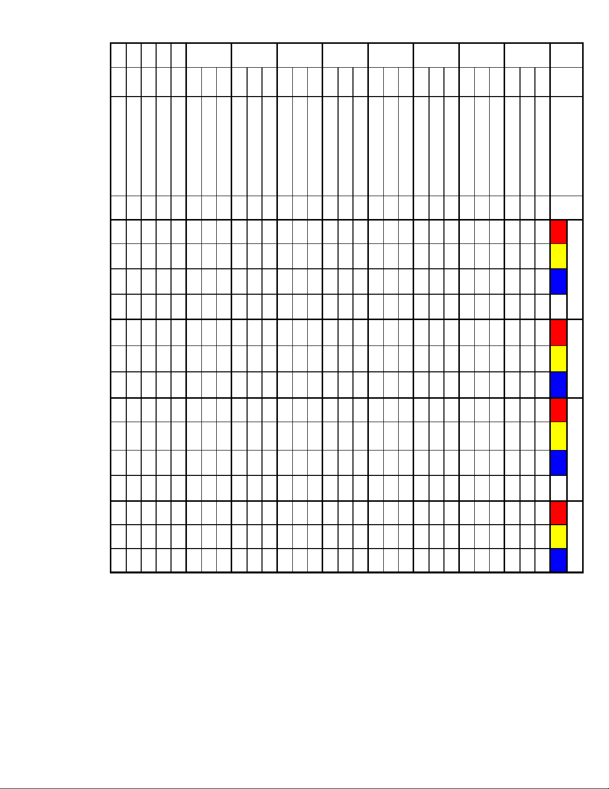
M180L Series Flash Pattern Chart:
13
12
10
11
9
29
28
26
27
Modulation NO N/C N/C N/C N/C N/C N/C N/C N/C N/C N/C N/C N/C N/C N/C
Steady Burn NO N/C N/C N/C N/C N/C N/C N/C N/C N/C N/C N/C N/C N/C N/C
25
Steady - Single NO N/C N/C N/C N/C N/C N/C N/C N/C N/C N/C N/C N/C N/C N/C
4 Single Flash ,2 Quad Flash Alt. NO N/C N/C N/C N/C N/C N/C N/C N/C N/C N/C N/C N/C N/C N/C
2 Double Flash,2 Triple Alt. NO N/C N/C N/C N/C N/C N/C N/C N/C N/C N/C N/C N/C N/C N/C
24
Quint Flash 150FPM Alt. yes N/C N/C N/C N/C N/C N/C N/C N/C N/C N/C N/C N/C N/C N/C
23
8
Quint Flash 150FPM sim. Phase2 yes Class 1 Class 1 Class 1 Class 1 N/C N/C N/C 120 100 100 60 N/C N/C N/C
22
Quint Flash 150FPM sim. Phase1 yes Class 1 Class 1 Class 1 Class 1 N/C N/C N/C 120 100 100 60 N/C N/C N/C
21
TripleAlter 75FPM Alt. yes N/C N/C N/C N/C N/C N/C N/C N/C N/C N/C N/C N/C N/C N/C
20
7
Triple 75FPM sim. Phase2 yes Class 1 Class 1 Class 1 Class 1 N/C N/C N/C 140 140 140 140 N/C N/C N/C
19
Triple 75FPM sim. Phase1 yes Class 1 Class 1 Class 1 Class 1 N/C N/C N/C 140 140 140 140 N/C N/C N/C
18
Quad Flash 150FPM Alt yes N/C N/C N/C N/C N/C N/C N/C N/C N/C N/C N/C N/C N/C N/C
17
6
Quad Flash 150FPM sim. Phase2 yes Class 1 Class 1 Class 1 Class 1 N/C N/C N/C 120 100 100 60 N/C N/C N/C
16
Quad Flash 150FPM sim. Phase1 yes Class 1 Class 1 Class 1 Class 1 N/C N/C N/C 120 100 100 60 N/C N/C N/C
15
Quad Flash 75FPM Alt. yes N/C N/C N/C N/C N/C N/C N/C N/C N/C N/C N/C N/C N/C N/C
5
14
Quad Flash 75FPM sim. Phase2 yes Class 1 Class 1 Class 1 Class 1 N/C N/C N/C 140 120 100 80 N/C N/C N/C
13-Default
12
Double Flash 120FPM Alt. yes N/C N/C N/C N/C N/C N/C N/C N/C N/C N/C N/C N/C N/C N/C
Quad Flash 75FPM sim. Phase1 yes Class 1 Class 1 Class 1 Class 1 N/C N/C N/C 140 120 100 80 N/C N/C N/C
4
11
Double Flash 120FPM sim. phase2 yes Class 1 Class 1 Class 1 Class 1 N/C N/C N/C 140 140 120 120 Class 2 Class 2 Class 2
10
Double Flash 120FPM sim. Phase1 yes Class 1 Class 1 Class 1 Class 1 N/C N/C N/C 140 140 120 120 Class 2 Class 2 Class 2
9
Double Flash 75FPM Alt. yes N/C N/C N/C N/C N/C N/C N/C N/C N/C N/C N/C N/C N/C N/C
8
3
Double Flash 75FPM sim. phase2 yes Class 1 Class 1 Class 1 Class 1 N/C N/C N/C 160 140 140 140 N/C N/C N/C
7
Double Flash 75FPM sim. Phase1 yes Class 1 Class 1 Class 1 Class 1 N/C N/C N/C 160 140 140 140 N/C N/C N/C
6
Single Flash 120FPM Alt. yes N/C N/C N/C N/C N/C N/C N/C N/C N/C N/C N/C N/C N/C N/C
5
2
Single Flash 120FPM sim. phase2 yes Class 1 Class 1 Class 1 Class 1 N/C N/C N/C 160 140 140 140 N/C N/C N/C
4
Single Flash 120FPM sim. Phase1 yes Class 1 Class 1 Class 1 Class 1 N/C N/C N/C 160 140 140 140 N/C N/C N/C
3
Single Flash 75FPM Alt. yes N/C N/C N/C N/C N/C N/C N/C N/C N/C N/C N/C N/C N/C N/C
2
1
Single Flash 75FPM sim. Phase2 yes Class 1 Class 1 Class 1 Class 1 Class B Class B Class B 160 140 140 140 N/C N/C N/C
Pattern MODE PATTERNS SYNC.
1
Single Flash 75FPM sim. Phase1 yes Class 1 Class 1 Class 1 Class 1 Class B Class B Class B 160 140 140 140 N/C N/C N/C
RED AMBER BLUE WHITE RED AMBER BLUE RED AMBER BLUE WHITE RED AMBER BLUE
SAE J595 CA T13 SAE J845 ECE R65
920-0661-00 Rev. C Page 3 of 8
Page 4

M180LMC Series Flash Pattern Chart:
3
13 13 25
14 14 26
15 15 27
12 20
PATTERN
2
10 10 18 Single 375FPMFPM (Color 1 Alternately Color 2) Alternately (Color 3 Alternately Color 4) yes N/C N/C N/C N/C N/C N/C N/C N/C N/C N/C N/C N/C N/C N/C
11 19
9 9 17 Single 375FPMFPM Ph2 (Color 1 Synchronous Color 3) Alternately (Color 2 Synchronous Color 4) yes N/C N/C N/C N/C N/C N/C N/C N/C N/C N/C N/C N/C N/C N/C
8 8 16 Single 375FPMFPM Ph1 (Color 1 Synchronous Color 3) Alternately (Color 2 Synchronous Color 4) yes N/C N/C N/C N/C N/C N/C N/C N/C N/C N/C N/C N/C N/C N/C
7 11 Single 375FPMFPM Ph2 Color 1 Synchronous Color 3 yes N/C N/C N/C N/C N/C N/C N/C N/C N/C N/C N/C N/C N/C N/C
6 10 Single 375FPMFPM Ph1 Color 1 Synchronous Color 3 yes N/C N/C N/C N/C N/C N/C N/C N/C N/C N/C N/C N/C N/C N/C
5 5 9 SAE/T13 Single 75FPM (Color 1 Alternately Color 2) Alternately (Color 3 Alternately Color 4) yes N/C N/C N/C N/C N/C N/C N/C N/C N/C N/C N/C N/C N/C N/C
4 4 8 SAE/T13 Single 75FPM Ph2(Color 1 Synchronous Color 3) Alternately (Color 2 Synchronous Color 4) yes N/C N/C N/C N/C N/C N/C N/C N/C N/C N/C N/C N/C N/C N/C
3 3 7 SAE/T13 Single 75FPM Ph1(Color 1 Synchronous Color 3) Alternately (Color 2 Synchronous Color 4) yes N/C N/C N/C N/C N/C N/C N/C N/C N/C N/C N/C N/C N/C N/C
1
(Red line)
1-Default 1 SAE/T13 SAE/T13 Single 75FPM Ph1 Color 1 Synchronous Color 3 yes Class 1 Class 1 Class1 Class1 Class B Class B Class B 160 140 140 140 N/C N/C N/C
2 2 SAE/T13 SAE/T13 Single 75FPM Ph2 Color 1 Synchronous Color 3 yes Class 1 Class 1 Class 1 Class 1 Class B Class B Class B 160 140 140 140 N/C N/C N/C
Color 1 &
Color 3
MODE 1
12 24
SAE/T13 Double 75FPM Ph1 (Color 1 Synchronous Color 3) Alternately (Color 2 Synchronous Color 4)
SAE/T13 Double 75FPM Ph2 (Color 1 Synchronous Color 3) Alternately (Color 2 Synchronous Color 4)
SAE/T13 Double 75FPM (Color 1 Alternately Color 2) Alternately (Color 3 Alternately Color 4)
SAE/T13 Double 75FPM Ph2 Color 2 Synchronous Color 4
11 23
21
22
SAE/T13 Double 75FPM Ph1 Color 1 Alternately Color 4
SAE/T13 Double 75FPM Ph2 Color 1 Alternately Color 4
SAE/T13 Double 75FPM Ph1 Color 2 Synchronous Color 4
SAE/T13 Double 75FPM Ph2 Color 1 Synchronous Color 3
SAE/T13 Double 75FPM Ph1 Color 1 Synchronous Color 3
7 15 Single 375FPMFPM Ph2 Color 2 Synchronous Color 4 yes N/C N/C N/C N/C N/C N/C N/C N/C N/C N/C N/C N/C N/C N/C
6 14 Single 375FPMFPM Ph1 Color 2 Synchronous Color 4 yes N/C N/C N/C N/C N/C N/C N/C N/C N/C N/C N/C N/C N/C N/C
13 Single 375FPMFPM Ph2 Color 1 Alternately Color 4 yes N/C N/C N/C N/C N/C N/C N/C N/C N/C N/C N/C N/C N/C N/C
12 Single 375FPMFPM Ph1 Color 1 Alternately Color 4 yes N/C N/C N/C N/C N/C N/C N/C N/C N/C N/C N/C N/C N/C N/C
2 6 SAE/T13 Single 75FPM Ph2 Color 2 Synchronous Color 4 yes Class 1 Class 1 Class 1 Class 1 Class B Class B Class B 160 140 140 140 N/C N/C N/C
1-Default 5 SAE/T13 Single 75FPM Ph1 Color 2 Synchronous Color 4 yes Class 1 Class 1 Class 1 Class 1 Class B Class B Class B 160 140 140 140 N/C N/C N/C
4 SAE/T13 Single 75FPM Ph2 Color 1 Alternately Color 4 yes N/C N/C N/C N/C N/C N/C N/C N/C N/C N/C N/C N/C N/C N/C
3 SAE/T13 Single 75FPM Ph1 Color 1 Alternately Color 4 yes N/C N/C N/C N/C N/C N/C N/C N/C N/C N/C N/C N/C N/C N/C
(White
line)
(Red line &
White line)
Color 4
Color 2 &
MODE 2
Color 4
Color 2 &
MODE 2
Color 3
Pattern SYNC.
Color 1 &
MODE 1
yes N/C N/C N/C N/C N/C N/C N/C N/C N/C N/C N/C N/C N/C N/C
yes N/C N/C N/C N/C N/C N/C N/C N/C N/C N/C N/C N/C N/C N/C
yes N/C N/C N/C N/C N/C N/C N/C N/C N/C N/C N/C N/C N/C N/C
yes Class 1 Class 1 Class 1 Class 1 N/C N/C N/C 160 140 140 140 N/C N/C N/C
yes Class 1 Class 1 Class 1 Class 1 N/C N/C N/C 160 140 140 140 N/C N/C N/C
yes N/C N/C N/C N/C N/C N/C N/C N/C N/C N/C N/C N/C N/C N/C
yes N/C N/C N/C N/C N/C N/C N/C N/C N/C N/C N/C N/C N/C N/C
yes Class 1 Class 1 Class 1 Class 1 N/C
N/C N/C 160 140 140 140 N/C N/C N/C
yes Class 1 Class 1 Class 1 Class 1 N/C N/C N/C 160 140 140 140 N/C N/C N/C
RED AMBER BLUE WHITE RED AMBER BLUE RED AMBER BLUE WHITE RED AMBER BLUE
SAE J595 CA T13 SAE J845 Class 1S ECE R65
920-0661-00 Rev. C Page 4 of 8
Page 5

30 30 54 SAE/T13 Quad 75FPM (Color 1 Alternately Color 2) Alternately (Color 3 Alternately Color 4) yes N/C N/C N/C N/C N/C N/C N/C N/C N/C N/C N/C N/C N/C N/C
29 29 53 SAE/T13 Quad 75FPM Ph2 (Color 1 Synchronous Color 3) Alternately (Color 2 Synchronous Color 4) yes N/C N/C N/C N/C N/C N/C N/C N/C N/C N/C N/C N/C N/C N/C
28 28 52 - Default SAE/T13 Quad 75FPM Ph1 (Color 1 Synchronous Color 3) Alternately (Color 2 Synchronous Color 4) yes N/C N/C N/C N/C N/C N/C N/C N/C N/C N/C N/C N/C N/C N/C
27 51 SAE/T13 Quad 75FPM Ph2 Color 2 Synchronous Color 4 yes Class 1 Class 1 Class 1 Class 1 N/C N/C N/C 140 140 120 120 N/C N/C N/C
6
26 50 SAE/T13 Quad 75FPM Ph1 Color 2 Synchronous Color 4 yes Class 1 Class 1 Class 1 Class 1 N/C N/C N/C 140 140 120 120 N/C N/C N/C
49 SAE/T13 Quad 75FPM Ph2 Color 1 Alternately Color 4 yes N/C N/C N/C N/C N/C N/C N/C N/C N/C N/C N/C N/C N/C N/C
48 SAE/T13 Quad 75FPM Ph1 Color 1 Alternately Color 4 yes N/C N/C N/C N/C N/C N/C N/C N/C N/C N/C N/C N/C N/C N/C
27 47 SAE/T13 Quad 75FPM Ph2 Color 1 Synchronous Color 3 yes Class 1 Class 1 Class 1 Class 1 N/C
26 46 SAE/T13 Quad 75FPM Ph1 Color 1 Synchronous Color 3 yes Class 1 Class 1 Class 1 Class 1 N/C N/C N/C 140 140 120 120 N/C N/C N/C
25 25 45 SAE/T13 Triple 75FPM (Color 1 Alternately Color 2) Alternately (Color 3 Alternately Color 4) yes N/C N/C N/C N/C N/C N/C N/C N/C N/C N/C N/C N/C N/C N/C
24 24 44 SAE/T13 Triple 75FPM Ph2 (Color 1 Synchronous Color 3) Alternately (Color 2 Synchronous Color 4) yes N/C N/C N/C N/C N/C N/C N/C N/C N/C N/C N/C N/C N/C N/C
23 23 43 SAE/T13 Triple 75FPM Ph1 (Color 1 Synchronous Color 3) Alternately (Color 2 Synchronous Color 4) yes N/C N/C N/C N/C N/C N/C N/C N/C N/C N/C N/C N/C N/C N/C
22 42 SAE/T13 Triple 75FPM Ph2 Color 2 Synchronous Color 4 yes Class 1 Class 1 Class 1 Class 1 N/C N/C N/C 160 140 140 140 N/C N/C N/C
5
21 41 SAE/T13 Triple 75FPM Ph1 Color 2 Synchronous Color 4 yes Class 1 Class 1 Class 1 Class 1 N/C N/C N/C 160 140 140 140 N/C N/C N/C
40 SAE/T13 Triple 75FPM Ph2 Color 1 Alternately Color 4 yes N/C N/C N/C N/C N/C N/C N/C N/C N/C N/C N/C N/C N/C N/C
39 SAE/T13 Triple 75FPM Ph1 Color 1 Alternately Color 4 yes N/C N/C N/C N/C N/C N/C N/C N/C N/C N/C N/C N/C N/C N/C
22 38 SAE/T13 Triple 75FPM Ph2 Color 1 Synchronous Color 3 yes Class 1 Class 1 Class 1 Class 1 N/C N/C N/C 160 140 140 140 N/C N/C N/C
21 37 SAE/T13 Triple 75FPM Ph1 Color 1 Synchronous Color 3 yes Class 1 Class 1 Class 1 Class 1 N/C N/C N/C 160 140 140 140 N/C N/C N/C
20 20 36 ECER65/SAE Double 120FPM (Color 1 Alternately Color 2) Alternately (Color 3 Alternately Color 4) yes N/C N/C N/C N/C N/C N/C N/C N/C N/C N/C N/C N/C N/C N/C
19 19 35 ECER65/SAE Double 120FPM Ph2 (Color 1 Synchronous Color 3) Alternately (Color 2 Synchronous Color 4) yes N/C N/C N/C N/C N/C N/C N/C N/C N/C N/C N/C N/C N/C N/C
18 18 34 ECER65/SAE Double 120FPM Ph1 (Color 1 Synchronous Color 3) Alternately (Color 2 Synchronous Color 4) yes N/C N/C N/C N/C N/C N/C N/C N/C N/C N/C N/C N/C N/C N/C
17 33 ECER65/SAE Double 120FPM Ph2 Color 2 Synchronous Color 4 yes Class 1 Class 1 Class 1 Class 1 N/C N/C N/C 140 140 120 120 Class 2 Class 2 Class 2
4
16 32 ECER65/SAE Double 120FPM Ph1 Color 2 Synchronous Color 4 yes Class 1 Class 1 Class 1 Class 1 N/C N/C N/C 140 140 120 120 Class 2 Class 2 Class 2
31 ECER65/SAE Double 120FPM Ph2 Color 1 Alternately Color 4 yes N/C N/C N/C N/C N/C N/C N/C N/C N/C N/C N/C N/C N/C N/C
30 ECER65/SAE Double 120FPM Ph1 Color 1 Alternately Color 4 yes N/C N/C N/C N/C N/C N/C N/C N/C N/C N/C N/C N/C N/C N/C
17 29 ECER65/SAE Double 120FPM Ph2 Color 1 Synchronous Color 3 yes Class 1 Class 1 Class 1 Class 1 N/C N/C N/C 140 140 120 120 Class 2 Class 2 Class 2
16 28 ECER65/SAE Double 120FPM Ph1 Color 1 Synchronous Color 3 yes Class 1 Class 1 Class 1 Class 1 N/C N/C N/C 140 140 120 120 Class 2 Class 2 Class 2
(Red line)
(White
line)
(Red line &
White line)
Color 4
PATTERN
Color 1 &
MODE 1
Color 3
Color 2 &
MODE 2
Color 4
Color 2 &
MODE 2
Color 3
Pattern SYNC.
Color 1 &
MODE 1
N/C N/C 140 140 120 120 N/C N/C N/C
RED AMBER BLUE WHITE RED AMBER BLUE RED AMBER BLUE WHITE RED AMBER BLUE
SAE J595 CA T13 SAE J845 ECE R65 Class1
920-0661-00 Rev. C Page 5 of 8
Page 6

36 69 Steady burn-Color 2 & 4 no N/C N/C N/C N/C N/C N/C N/C N/C N/C N/C N/C N/C N/C N/C
(Red line)
(White
line)
(Red line &
White line)
Color 4
PATTERN
Color 1 &
MODE 1
Color 3
Color 2 &
MODE 2
Color 4
Color 2 &
MODE 2
Color 3
Pattern SYNC.
Color 1 &
MODE 1
12
36 68 Steady burn-Color 1 & 3 no N/C N/C N/C N/C N/C N/C N/C N/C N/C N/C N/C N/C N/C N/C
11 67 1Doube 1Triple 1Quad (Color 1 Synchronous Color 3) Alternately (Color 2 Synchronous Color 4) no N/C N/C N/C N/C N/C N/C N/C N/C N/C N/C N/C N/C N/C N/C
10 66 4 Single,2 Triple (Color 1 Synchronous Color 3) Alternately (Color 2 Synchronous Color 4) no N/C N/C N/C N/C N/C N/C N/C N/C N/C N/C N/C N/C N/C N/C
9 65 2 Double,2 Quad (Color 1 Synchronous Color 3) Alternately (Color 2 Synchronous Color 4) no N/C N/C N/C N/C N/C N/C N/C N/C N/C N/C N/C N/C N/C N/C
8 64 Modulation (Color 1 Synchronous Color 3) Alternately (Color 2 Synchronous Color 4) no N/C N/C N/C N/C N/C N/C N/C N/C N/C N/C N/C N/C N/C N/C
35 35 63 ECER65/SAE Quad 120FPM (Color 1 Alternately Color 2) Alternately (Color 3 Alternately Color 4) yes N/C N/C N/C N/C N/C N/C N/C N/C N/C N/C N/C N/C N/C N/C
34 34 62 ECER65/SAE Quad 120FPM Ph2 (Color 1 Synchronous Color 3) Alternately (Color 2 Synchronous Color 4) yes N/C N/C N/C N/C N/C N/C N/C N/C N/C N/C N/C N/C N/C N/C
33 33 61 ECER65/SAE Quad 120FPM Ph1 (Color 1 Synchronous Color 3) Alternately (Color 2 Synchronous Color 4) yes N/C N/C N/C N/C N/C N/C N/C N/C N/C N/C N/C N/C N/C N/C
32 60 ECER65/SAE Quad 120FPM Ph2 Color 2 Synchronous Color 4 yes Class 1 Class 1 Class 1 Class 1 N/C N/C N/C 140 140 140 120 N/C N/C N/C
7
31 59 ECER65/SAE Quad 120FPM Ph1 Color 2 Synchronous Color 4 yes Class 1 Class 1 Class 1 Class 1 N/C N/C N/C 140 140 140 120 N/C N/C N/C
58 ECER65/SAE Quad 120FPM Ph2 Color 1 Alternately Color 4 yes N/C N/C N/C N/C N/C N/C N/C N/C N/C N/C N/C N/C N/C N/C
57 ECER65/SAE Quad 120FPM Ph1 Color 1 Alternately Color 4 yes N/C N/C N/C N/C N/C N/C N/C N/C N/C N/C N/C N/C N/C N/C
32 56 ECER65/SAE Quad 120FPM Ph2 Color 1 Synchronous Color 3 yes Class 1 Class 1 Class 1 Class 1 N/C N/C N/C 140 140 140 120 N/C N/C N/C
31 55 ECER65/SAE Quad 120FPM Ph1 Color 1 Synchronous Color 3 yes Class 1 Class 1 Class 1 Class 1 N/C N/C N/C 140 140 140 120 N/C N/C N/C
RED AMBER BLUE WHITE RED AMBER BLUE RED AMBER BLUE WHITE RED AMBER BLUE
SAE J595 CA T13 SAE J845 Class 1S ECE R65 Class1
920-0661-00 Rev. C Page 6 of 8
Page 7

TROUBLESHOOTING
M180L and M180LMC series have been factory tested and approved. If the device fails, please check the following:
1. Check the wiring to the device has not short circuited.
2. Make sure the Red and or white, and black wires are securely connected to power and ground separately.
920-0661-00 Rev. C Page 7 of 8
Page 8

Manufacturer Limited Warranty Policy:
Manufacturer warrants that on the date of purchase this product will conform to Manufacturer’s specifications for this product (which are
available from the Manufacturer upon request). This Limited Warranty extends for Sixty (60) months from the date of purchase.
DAMAGE TO PARTS OR PRODUCTS RESULTING FROM TAMPERING, ACCIDENT, ABUSE, MISUSE, NEGLIGENCE, UNAPPROVED MODIFICATIONS, FIRE OR OTHER HAZARD; IMPROPER INSTALLATION OR OPERATION; OR NOT BEING MAINTAINED IN ACCORDANCE WITH THE
MAINTENANCE PROCEDURES SET FORTH IN MANUFACTURER’S INSTALLATION AND OPERATING INSTRUCTIONS VOIDS THIS LIMITED
WARRANTY.
Exclusion of Other Warranties:
MANUFACTURER MAKES NO OTHER WARRANTIES, EXPRESS OR IMPLIED. THE IMPLIED WARRANTIES FOR MERCHANTABILITY, QUALITY
OR FITNESS FOR A PARTICULAR PURPOSE, OR ARISING FROM A COURSE OF DEALING, USAGE OR TRADE PRACTICE ARE HEREBY
EXCLUDED AND SHALL NOT APPLY TO THE PRODUCT AND ARE HEREBY DISCLAIMED, EXCEPT TO THE EXTENT PROHIBITED BY APPLICABLE LAW. ORAL STATEMENTS OR REPRESENTATIONS ABOUT THE PRODUCT DO NOT CONSTITUTE WARRANTIES.
Remedies and Limitation of Liability:
MANUFACTURER’S SOLE LIABILITY AND BUYER’S EXCLUSIVE REMEDY IN CONTRACT, TORT (INCLUDING NEGLIGENCE), OR UNDER ANY
OTHER THEORY AGAINST MANUFACTURER REGARDING THE PRODUCT AND ITS USE SHALL BE, AT MANUFACTURER’S DISCRETION, THE
REPLACEMENT OR REPAIR OF THE PRODUCT, OR THE REFUND OF THE PURCHASE PRICE PAID BY BUYER FOR NON-CONFORMING
PRODUCT. IN NO EVENT SHALL MANUFACTURER’S LIABILITY ARISING OUT OF THIS LIMITED WARRANTY OR ANY OTHER CLAIM RELATED TO THE MANUFACTURER’S PRODUCTS EXCEED THE AMOUNT PAID FOR THE PRODUCT BY BUYER AT THE TIME OF THE ORIGINAL
PURCHASE. IN NO EVENT SHALL MANUFACTURER BE LIABLE FOR LOST PROFITS, THE COST OF SUBSTITUTE EQUIPMENT OR LABOR,
PROPERTY DAMAGE, OR OTHER SPECIAL, CONSEQUENTIAL, OR INCIDENTAL DAMAGES BASED UPON ANY CLAIM FOR BREACH OF
CONTRACT, IMPROPER INSTALLATION, NEGLIGENCE, OR OTHER CLAIM, EVEN IF MANUFACTURER OR A MANUFACTURER’S REPRESENTATIVE HAS BEEN ADVISED OF THE POSSIBILITY OF SUCH DAMAGES. MANUFACTURER SHALL HAVE NO FURTHER OBLIGATION OR
LIABILITY WITH RESPECT TO THE PRODUCT OR ITS SALE, OPERATION AND USE, AND MANUFACTURER NEITHER ASSUMES NOR
AUTHORIZES THE ASSUMPTION OF ANY OTHER OBLIGATION OR LIABILITY IN CONNECTION WITH SUCH PRODUCT.
This Limited Warranty defines specific legal rights. You may have other legal rights which vary from jurisdiction to jurisdiction. Some
jurisdictions do not allow the exclusion or limitation of incidental or consequential damages.
Product Returns:
If a product must be returned for repair or replacement*, please contact our factory to obtain a Return Goods Authorization Number (RGA
number) before you ship the product to Code 3®, Inc. Write the RGA number clearly on the package near the mailing label. Be sure you use
sufficient packing materials to avoid damage to the product being returned while in transit.
*Code 3®, Inc. reserves the right to repair or replace at its discretion. Code 3®, Inc. assumes no responsibility or liability for expenses incurred for the removal and /or reinstallation of products requiring service and/or repair.; nor for the packaging,
handling, and shipping: nor for the handling of products returned to sender after the service has been rendered.
10986 North Warson Road
St. Louis, MO 63114
Technical Service
(314) 996-2800
c3_tech_support@code3esg.com
www.code3esg.com
An ECCO SAFETY GROUP™ Company
www.eccosafetygroup.com
© 2017 Code 3, Inc. all rights reserved.
920-0661-00 Rev. C Page 8 of 8
 Loading...