

Page 1
INSTALLATION
&
OPERATION
MANUAL
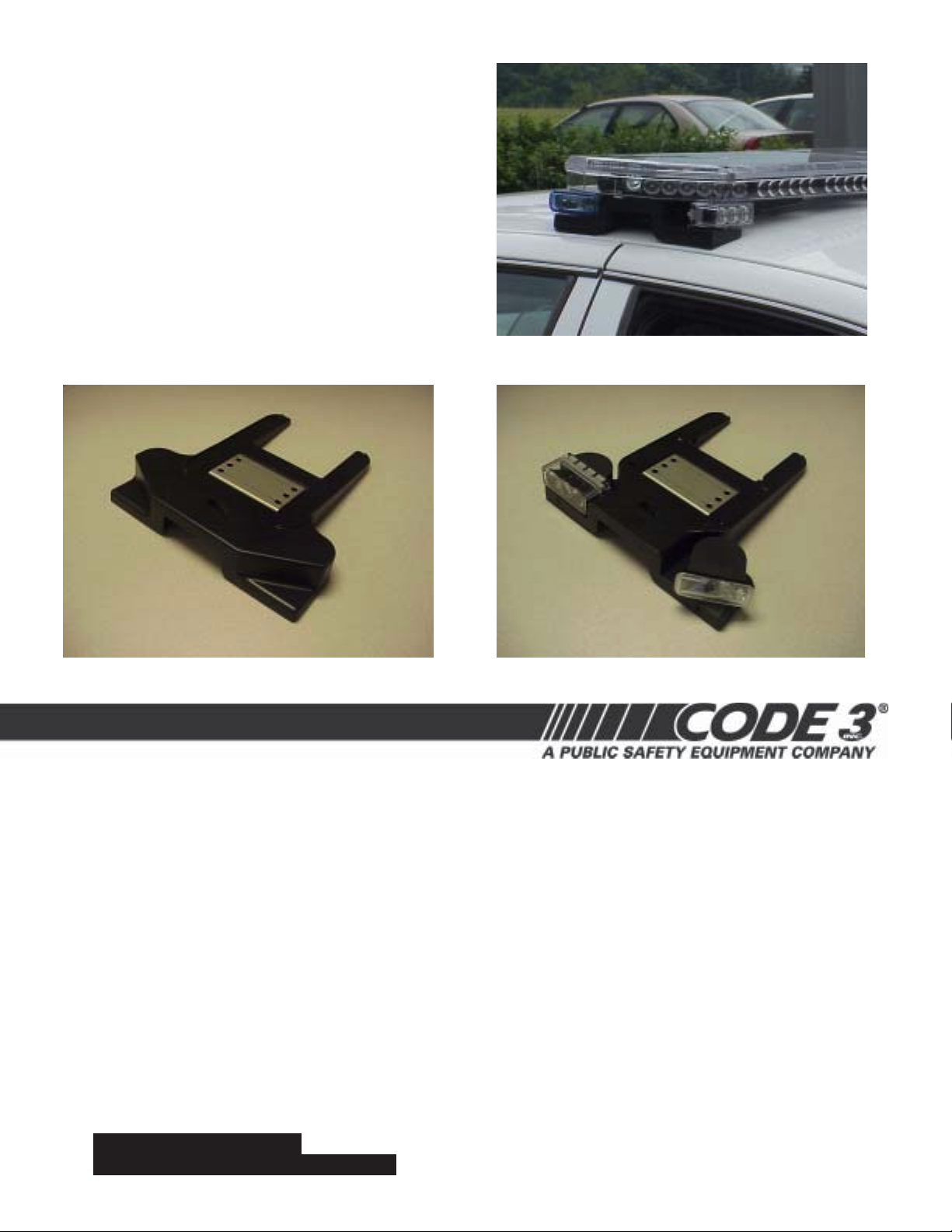
Lighted VersionStandard Version
LIT3 Mounting Kit
CONTENTS:
Introduction.....................................................................................2
Unpacking and Pre-Installation.........................................................2
Installation and Mounting-Standard Mount.........................................2-8
55 Watt Lamp Replacement.............................................................8
Mounting-Permanent Mount..............................................................9
Retrofit Lighted Mounting Kit to existing Lightbar...............................10
Wiring Instructions..........................................................................10
LED Flash Pattern Selection ...........................................................11
Maintenance and Troubleshooting....................................................11
Parts List.......................................................................................12
Notes.............................................................................................13-15
Warranty........................................................................................16
For future reference, record your product's serial no. here __________________________________________
Read all instructions and warnings before installing and using.
INSTALLER:
This manual must be delivered to the end user of this equipment.IMPORTANT:
Page 2

Introduction
The new LIT3 Mounting Kit is a system that provides an attractive and convenient means to attach many of the Code 3 Lightbar Products
to Emergency Vehicles.
The Lighted Version can be ordered with 55 watt takedown/alley lights and/or 3 LED optix lightheads in Red, White, Blue or Amber.
The use of this or any warning device does not ensure that all drivers can or will observe or react to an emer-
!
WARNING!
gency warning signal. Never take the right-of-way for granted. It is your responsibility to be sure you can proceed
safely before entering an intersection, driving against traffic, responding at a high rate of speed, or walking on or
around traffic lanes.
The effectiveness of this warning device is highly dependent upon correct mounting and wiring. Read and follow
the manufacturer’s instructions before installing or using this device. The vehicle operator should insure daily that
all features of the device operate correctly. In use, the vehicle operator should insure the projection of the
warning signal is not blocked by vehicle components (i.e. open trunks or compartment doors), people, vehicles, or
other obstructions.
This equipment is intended for use by authorized personnel only. It is the user’s responsibility to understand and
obey all laws regarding emergency warning devices. The user should check all applicable city, state and federal
laws and regulations.
Code 3, Inc., assumes no liability for any loss resulting from the use of this warning device.
Proper installation is vital to the performance of this warning device and the safe operation of the emergency
vehicle. It is important to recognize that the operator of the emergency vehicle is under psychological and
physiological stress caused by the emergency situation. The warning device should be installed in such a manner
as to: A) Not reduce the output performance of the system, B) Place the controls within convenient reach of the
operator so that he can operate the system without losing eye contact with the roadway.
Emergency warning devices often require high electrical voltages and/or currents. Properly protect and use
caution around live electrical connections. Grounding or shorting of electrical connections can cause high current
arcing, which can cause personal injury and/or severe vehicle damage, including fire.
PROPER INSTALLATION COMBINED WITH OPERATOR TRAINING IN THE PROPER USE OF EMERGENCY WARNING DEVICES IS ESSENTIAL TO INSURE THE SAFETY OF EMERGENCY PERSONNEL
AND THE PUBLIC.
Unpacking & Pre-installation
Carefully remove the LIT3 Mounting Kit from the shipping carton, taking care not to scratch the lenses of the LED Lightheads (if so
equipped). Examine the unit for transit damage, etc. Report any damage to the carrier and keep the shipping carton.
Standard lightbars are built to operate on 12 volt D.C. negative ground (earth) vehicles. If you have an electrical system other than 12
volt D.C. negative ground (earth), and have not ordered a specially wired lightbar, contact the factory for instructions.
If the units you have are the lighted version, test the unit before installation. To test, touch the black wire to the ground (earth) and the red
wire to +12 volts D.C.,
Installation & Mounting
Utilizing non-factory supplied screws and/or mounting brackets and/or the improper
!
WARNING!
number of screws may result in loss of warranty coverage on the equipment.
Do not attempt to attach the mounting feet in any manner
other than described in the following pages. Do not drill
holes through the mounting feet and attach with fasteners
to the vehicle frame. This will void the warranty.
Mounting Hardware -
All mounting hardware is packed in a small bag inside the main carton. The main components in the kit are (2) Molded Plastic Mounting
Feet, (2) Stainless Steel Mounting Brackets, (2) Gutter Hooks, and other required hardware. These are all discussed in detail later
2
Page 3
Installation Instructions
Installer Note: If the LIT3 Mounting Kit being installed is a Lighted Version, proceed with the following steps! If the
Mounting Kit being installed is the Standard Version, skip Steps 1 through 8 and start with Step 9 on page 4 of this manual!
LIT3 Mounting Kit - Lighted Version
Step 1 Make sure the lightheads on the Mounting Kit are positioned in the desired location and orientation with respect to the Lightbar
(Example: Takedowns aimed toward the front, Alley Lights aimed toward the sides, and or Lightheads angled as desired, etc.) If the
location or orientation of the lightheads is O.K. skip Steps 2 through 8 and continue on from Step 9.
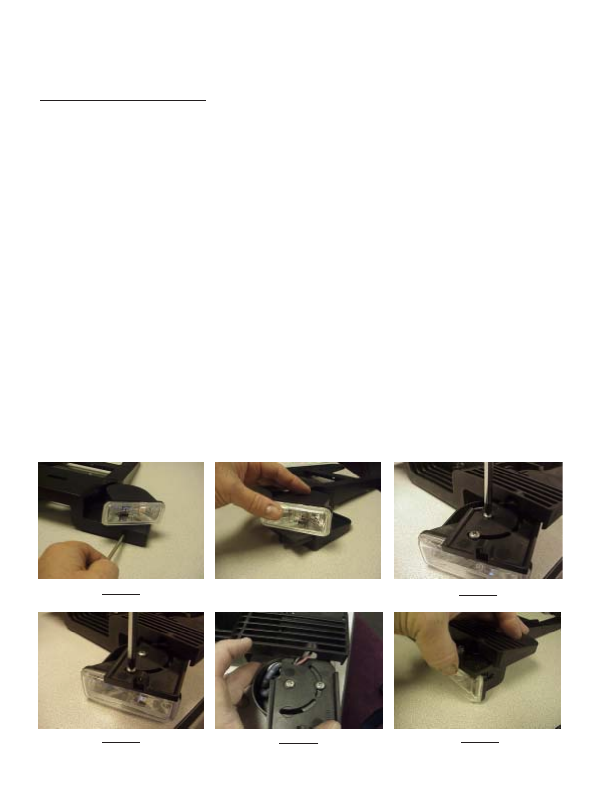
Step 2 If the location or orientation of the Lightheads must be adjusted, remove the #6 X 1/2" Slide Retention Screw with a #15 Torx Driver
(see Figure 1).
Note: The the 55 Watt Takedown lights are shown in the photos in Figures 1 through 6 below but the steps are the same for
the 3 LED OPTIX Lightheads!
Step 3 Pull out the Lighthead/Slide Shelf (see Figure 2).
Step 4 With the Lighthead/Slide Shelf removed, loosen the #8-32 X 1/4" Long Lighthead Mounting Screw with a #2 Phillips screwdriver (see
Figure 3). Note: This is the screw that the Lighthead Pivots on.
Step 5 Loosen the #8-32 X 1/4" Long Lighthead Mounting Screw closest to the front of the Lighthead's Lens (see Figure 4). Note: This is
the screw that locks and holds the Lighthead in position.
Step 6 Rotate the light on the slide shelf to the desired position and retighten the two Lighthead Mounting Screws. Note: It may be
necessary to remove the front Lighthead Mounting Screw shown in Figure 4 to bypass the support rib and then replace it
when the desired position is achieved.
Step 7 Tuck the wire connecters and the wires back into the Lighthead Cover leaving as little wire out of the cover as possible and making
sure thay are still engaged in the T-Slot in the slide shelf (see Figure 5). Carefully slide the Light Head Slide Shelf back into position while
guiding the wires into the gap provided between the Slide Shelf and the Mounting Foot (see Figure 6). Care should be taken to not pinch the
wires at the rear of the slide shelf.
Step 8 Replace the #6 X 1/2" Slide Retention Screw with a #15 Torx Driver again as shown in Figure 1.
FIGURE 1
FIGURE 2
FIGURE 3
FIGURE 4
FIGURE 5
3
FIGURE 6
Page 4
Installation Instructions-Cont.
Note: The following Steps 9 through 13 are the same for both Lighted Mounting Kits and Standard Kits (The Lighted Version is
shown)
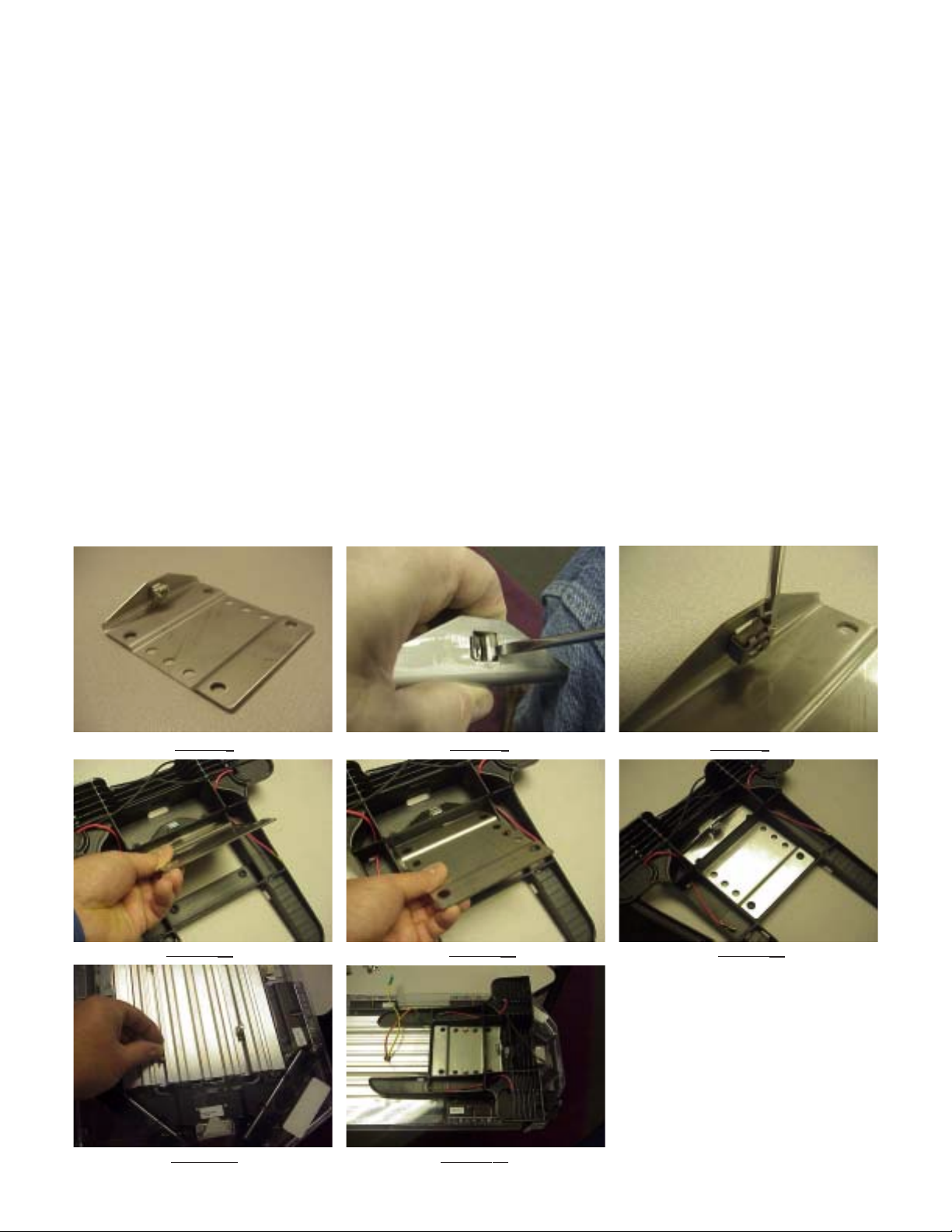
Note: Before proceeding with Step 9, make sure that the cage nuts are installed on the interior side of the
Stainless Steel Mounting Plates as shown in Figure 7 below. If the cage nut is not in the hole, slip one of the
ears of the cage nut into the square hole and use a screwdriver on the opposite side like a shoehorn to install
the cage nut into the hole as shown in Figure 8. If, after the cage nut is installed, the nut seems overly loose or
ready to fall out, use a slender screwdriver to pry the ears of the cage nut outward as shown in Figure 9 to
insure that it is retained during the remainder of the installation.
Step 9 Making sure any wires are out of the way on the Lighted Version of the Mounting Foot, position a Stainless Steel Mounting Plate through
the slot in the mounting foot (see Figures 10& 11) and into position over the locating bosses on each mounting foot (see Figure 12). Note: The
cage nut must be positioned as shown on the interior side of the mounting plate.
Step 10 Lay the Lightbar upside down on a clean, flat, padded surface (to protect the lenses from being scratched).
Step 11Slide (2) of the 5/16"-18 Carriage bolts on each side of the Lightbar into the slots in the lightbar's frame (see Figure 13).
Step 12 Position a Mounting Foot on each side of the Lightbar over the carriage bolts (see Figure 14).
FIGURE 7 FIGURE 8 FIGURE 9
FIGURE 10 FIGURE 11 FIGURE 12
FIGURE 13 FIGURE 14
4
Page 5
Installation Instructions-Cont.
Note: If you are installing a Standard Version of the Mounting Kit, skip Steps 13 through 16 and proceed with Step 17
Standard Version" at the bottom of page 6 of this manual.
"
Step 13 Feed the ends of the power wires from the Lightbar through the holes in the Mounting Feet and into the Mounting Foot Wire Pockets (see
Figure 15) (See addendum for installation of the through-the-frame wires if your Lightbar is not equipped)
Step 14 Plug the ends of the power wires from the Lightbar into the power wires from the Mounting Feet (see Figure 16)
Step 15 Tuck the excess lengths of the power wires into the Mounting Foot Wire Pockets (see Figure 17)
Step 16 Position the wire covers into the Mounting Foot Wire Pockets (see Figure 18), insert a #8 X 1/4" Sheet Metal Screw into it's mounting hole
(see Figure 19), and tighten the Sheet Metal Screw with a 1/4" hex Driver or a #20 Torx bit (see Figure 20)
FIGURE 15 FIGURE 16 FIGURE 17
FIGURE 19 FIGURE 20FIGURE 18
Step 17 Lighted Version Slip the Ring Terminal Ends of the Black Ground Wire under the rib on the Mounting Feet (see Figure 21), over
the ends of the
Carriage Bolts (see Figure 23). At this point the assembly should look as shown in Figure 24.
5/16"-18 Carriage bolts (see Figure 22) and position a 5/16" split washer and thread a 5/16"-18 Hex Nut onto each of the
FIGURE 21 FIGURE 22 FIGURE 23
FIGURE 24
5
Page 6

Special Instructions - Lightbar Internal Wiring
LIT3 mounting kit lightheads may be wired to operate in conjunction with lightheads mounted in the lightbar. Wire jumper T09831 is
provided for a convenient "Y" connection between these lightheads in most Code3 lightbars. (See the example shown below)
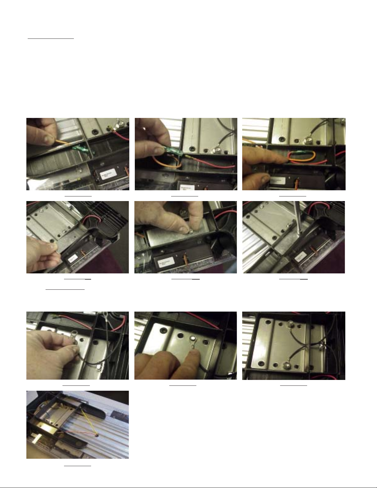
Step A To connect the takedown lightheads in the Mounting Kit with those in the Lightbar, locate and unplug the quick slide connector to the
existing takedown lighthead inside the lightbar as shown in Figures 25 and 26 below.
Step B Connect the male quick slide terminal of the T09831 wire jumper supplied in the parts bag to the female quick slide terminal of the lightbar's
takedown power wire disconnected in step A as shown in Figure 27 below.
Step C Connect the female quick slide terminal of the short leg of the T09831 wire jumper to the male quick slide terminal of the lightbar's takedown
lighthead disconnected in step A as shown in Figure 28 below.
Step D Connect the female quick slide terminal of the long leg of the T09831 wire jumper to the male quick slide terminal of the wire passing through
the lightbar frame and connected to the takedown light in the LIT3 Mounting Kit as shown in Figure 29. When the wires are connected correctly they
will look as shown in Figure 30.
Step E Repeat these steps for all (4) Lightheads of the Mounting Kit, then bundle the wires and wire tie them to the other wires inside
the lightbar as shown in Figure 31.
FIGURE 25 FIGURE 26 FIGURE 27
FIGURE 28 FIGURE 29 FIGURE 30
FIGURE 31
Installation Instructions-Cont.
Step 17 Standard Version Position a 5/16" split washer and thread the 5/16"-18 Hex Nut onto the Carriage Bolts (see Figure 32)
FIGURE 32
6
Page 7

Installation Instructions-Cont.
Step 18 To position the mounting feet on the Light bar Frame, measure the distance specified below from the outer edge of the Light bar Lens to the
face of the Mounting Foot and tighten the 5/16"-18 Hex Nut with a 1/2" socket wrench making sure the legs of the Mounting Feet are parallel to the
Lightbar Frame.
For the Ford Crown Victoria-Measure 1" from the outer edge of the Lightbar Lens to the outer Mounting Foot Face (see Figure 33)
For the 2005 Chevy Impala-Make the the outer edge of the Lightbar Lens flush to the outer face of the Mounting Foot (see Figure 34)
Note: The above measurements were based on a 47 inch Lightbar and 2005/2006 model year vehicles, for future or other vehicle models
or Customer personal preferance, the measurements may need to be adjusted as needed.
FIGURE 33 FORD CROWN VICTORIA FIGURE 34 CHEVROLET IMPALA
Step 19 Attach the Wedge Shaped Rubber Mounting Foot Pad by pushing the christmas tree shaped rib feature into the space between the
two center ribs on the Mounting Feet as shown in Figure 35. Make sure the thickest side of the pad is toward the outside also as shown in
Figure 35. The pads when installed to the Mounting feet properly will look as shown in Figure 36. If installed in the reversed position, the
pads may easily fall out if jostled. Note: The Permanent mount version of the Rubber Mounting Foot Pad has a differant shape to
work on flat surfaces (see Figure 37).
Note: There are (4) Mounting Foot Pad Spacers included in the hardware package for additional padding or adjustment of the
Mounting Kit to improve the fit to the vehicle's roof contour. The Mounting Foot Pad Spacers have adhesive to allow them to
be attached to the Mounting Foot Pads. If adjustment is required peel away the protective paper to expose the adhesive and
attach it to the flat side of the Rubber Mounting Foot Pad Wedges. It is best to place the Lightbar in position on the vehicle
to determine if Mounting Foot Pad Spacers are required to obtain a level fit or to prevent the bar from touching the roof at the
center.
FIGURE 35 FIGURE 36 FIGURE 37
Note: For Installation instructions of permanent mount version skip to Step 1 on page 9 of this Manual!
Step 20 Standard Mount Position one of the Gutter Hooks on the vehicle with the large mounting hole centered in the gap between the front and rear
doors of the vehicle and use it as a template to mark the mounting holes for drilling. If necessary, pull the vehicle's weatherstripping out of the way or in
some cases it may require trimming the weatherstripping.
Step 21 Drill the Mounting holes with a 3/32" drill. Note: Make sure the holes are drilled deep enough for the screws as on some vehicles there
are two layers of sheet metal to drill through in the gutter area!
Step 22 Apply soft pads between the Gutter Hook and the vehicle's roof if needed to protect the Vehicle's finish. Apply user supplied RTV Sealant to
each of the holes and to the heads of the sheet metal screws to prevent rust and seal against leaks. Install the sheet metal screws through the holes in
the gutter hook and into the holes drilled in step 9 with a 1/4" hex driver or socket. Make sure all screws are bottomed out and tight against the gutter
hook and the sheet metal of the vehicle.
Step 23 Re-attach the vehicle's weatherstripping if applicable.
7
Page 8

Installation Instructions-Cont.
Step 24 After the Lightbar Cable has been routed as desired, position the Lightbar on the roof of the vehicle and center it left to right, then align the
Lightbar front to back on the vehicle so that it is centered with the previously installed Gutter Hooks.
Step 25 Thread the 5/16"-18 X 3" long Screws (one on each side of the Lightbar) through mounting hole in the gutter hook and into the threads in
the Square Cage Nut in the Stainless Steel Mounting Bracket (see Figure 38)
Note: Depending on the vehicle model and location chosen for mounting the Lightbar, a different length screw may be required.
Stainless steel screws may be purchased at a local hardware store.
Step 26 Tighten the 5/16"-18 X 3" long Screws to a maximum torque of 30 inch pounds.
Note: Do Not Over Torque! Over-tightening does not improve the secureness of the lightbar to the vehicle but is actually detrimental
since it puts unnecessary stress on the lightbar, the mounting foot components, and the vehicle's roof.
FIGURE 38
55 Watt Lamp-Replacement
Step 1 Refer to step #2 page 3 of the installation instructions in this manual for removal of the Lighthead.
Step 2 Loosten the (2) Lighthead Cover mounting screws on the sides of the 55 Watt Lighthead with a Phillips screwdriver and remove the
cover (see Figure 39).
Step 3 Remove the (4) Bulb Cover Mounting Screws with a Phillips screwdriver (see Figure 40).
Step 4 Remove the (2) Bulb Mounting Screws with a Phillips screwdriver (see Figure 41) and remove the bulb.
Step 5 Replace the bulb and replace and tighten the (2) Bulb Mounting Screws making sure to replace and retain the black ground wire with one
of the Bulb Mounting Screws.
Note: Replacement 55 watt bulbs are available from Code 3 Inc. or you may obtain the bulb from your local auto parts store. If you
obtain the bulb from your local auto parts store it may be necessary to change the terminal on the power wire to mate with the
new bulb's terminal (depending on the bulb manufacturer). This terminal (fully insulated 1/4" female quickslide) is also available at
your local auto parts or hardware store.
Step 7 Carefully position the wires in the two wire slots (see Figure 42), replace the Bulb Cover, and replace and tighten the (4) Bulb Cover
Mounting Screws.
Step 8 Replace the Lighthead Cover and replace and tighten the (2) mounting screws on the sides of the 55 Watt Lighthead.
Step 9 Replace the 55 Watt Lighthead following Steps 7 and 8 on page 3 of this manual.
FIGURE 39 FIGURE 40 FIGURE 41 FIGURE 42
8
Page 9

Installation Instructions-Permanent Mount.
Step 1 Permanent Mount Determine the location for the lightbar on the vehicle and check that no equipment or wiring will be damaged when
drilling holes in the vehicle to mount the lightbar.
Step 2 Install a 5/16" split lock washer and a 5/16" flat washer onto each of the the 5/16-18 X 3" long Screws as shown in Figure 43. Position the
Permanent Mount Mounting Brackets and align the slot in the Brackets with the threaded hole in the cage nut as shown in Figure 44.
Step 3 Hold the Permanent Mount Mounting Brackets in place and thread the 5/16-18 X 3" long Screw into the cage nut in the stainless steel
mounting bracket as shown in Figure 45. Thread the 5/16-18 X 3" long Screw all the way in until it is finger tight against the Permanent Mount
Mounting Bracket (see Figure 46). Note: The 5/16-18 screw is purposefully 3" long to allow easy re-installation if the lightbar is
removed for maintenance by the Customer.
Step 4 Position the lightbar onto the surface of the vehicle and locate it as desired, then push the Permanent Mount Mounting Brackets down so
that they are in full contact with the mounting surface of the vehicle (see Figure 47).
Step 5 With a short pencil or other marking device, mark the four hole locations using the square holes in the Permanent Mount Mounting
Brackets as a template.
Step 6 Remove the lightbar and drill a 3/8" diameter hole through the vehicle's roof at the four mounting hole locations.
Step 7 After the lightbar's cable has been routed as desired you are ready to install the lightbar.
Step 8 Apply user supplied RTV sealant all around the four drilled holes in the vehicle's roof.
Step 9 Apply user supplied RTV sealant all around under the heads of four user supplied 5/16-18 carriage bolts and insert them through the
square holes in the Permanent Mount Mounting Brackets as shown in Figure 48.
Step 10 Reposition the lightbar over the vehicle's roof and lower the lightbar into position while carefully guiding the four carriage bolts through
the drilled holes in the vehicle's roof.
Step 11 Install appropriate user supplied fender washers, lock washers, and 5-16-18 hex nuts onto the carriage bolts and tighten the four 5/16-
18 hex nuts.
Step 12 Tighten the two 5/16-18 X 3" long Screws.
FIGURE 43 FIGURE 44 FIGURE 45
FIGURE 46 FIGURE 47 FIGURE 48
9
Page 10

Retrofit existing lightbars with wiring for the LIT3 Mounting Kit lighted version
Step 1 Mark the location for the Mounting Kit wire grommet's two holes near the center and 9 1/2" from each end of the lightbar's frame. A flat
area is needed that is 1/2" in diameter minimum to accept a 3/8" diameter hole. (see Figures 49 and 50).
Step 2 Drill a 3/8" diameter hole at the two locations for the Mounting Kit wire grommet. (see Figure 51).
Step 3 Feed the two terminals with the round plastic sleeve through the 3/8" hole from the internal side of the Lightbar and pull the wires to pop
the grommet into the hole (see Figure 52) Note: It is helpful to use a blunt tool to gently push the Grommet into the hole so that the
sealing groove pops into the frame hole.
Step 4 Connect the quick slides to the desired wires inside the light bar (see page 6 for light bar internal wiring connection instructions) and follow
the installation instructions starting at page 3 of this manual.
FIGURE 49 FIGURE 50 FIGURE 51 FIGURE 52
Larger wires and tight connections will provide longer service life for components. For
high current wires it is highly recommended that terminal blocks or soldered connections
!
WARNING!
be used with shrink tubing to protect the connections. Do not use insulation displacement connectors (e.g. 3M® Scotchlock type connectors). Route wiring using grommets
and sealant when passing through compartment walls. Minimize the number of splices
to reduce voltage drop. High ambient temperatures (e.g. underhood) will significantly
reduce the current carrying capacity of wires, fuses, and circuit breakers. Use "SXL"
type wire in engine compartment. All wiring should conform to the minimum wire size
and other recommendations of the manufacturer and be protected from moving parts and
hot surfaces. Looms, grommets, cable ties, and similar installation hardware should be
used to anchor and protect all wiring. Fuses or circuit breakers should be located as
close to the power takeoff points as possible and properly sized to protect the wiring and
devices. Particular attention should be paid to the location and method of making
electrical connections and splices to protect these points from corrosion and loss of
conductivity. Ground terminations should only be made to substantial chassis components, preferably directly to the vehicle battery. The user should install a fuse sized to
approximately 125% of the maximum Amp capacity in the supply line to protect against
short circuits. For example, a 30 Amp fuse should carry a maximum of 24 Amps. DO
NOT USE 1/4" DIAMETER GLASS FUSES AS THEY ARE NOT SUITABLE FOR
CONTINUOUS DUTY IN SIZES ABOVE 15 AMPS. Circuit breakers are very sensitive
to high temperatures and will "false trip" when mounted in hot environments or operated
close to their capacity.
LED WARNING MODULES-WIRING
LED Fusing Considerations
Although the average current draw per module is very low, due to the type of circuit used to power each
module, the instantaneous peak current to a module can be significantly higher during low voltage
conditions. To avoid prematurely blowing ATO style fuses or tripping breakers it is recommended the
following rule-of-thumb be used to size fuses or breakers. This is especially important in lightbars with
many LED modules running off a single fused source.
Minimum fuse size calculation:
For LED 12 volt electrical current
1.5 x (number of modules being fused)
Example: 2 intersection modules and 6 directional modules.
Minimum fuse requirement for single fuse - 1.5 (8) = 12 A
10
Page 11

WARNING!
!
This Product contains high intensity LED devices. To prevent eye damage,
DO NOT stare into light beam at close range.
Features and Specifications:
Operating Voltage: 10-16Vdc Reverse Polarity Protection.
Flashing Current Draw: Red/Amber: - .25A Avg.
Blue/White: - .4A Avg.
Steady Burn Current Draw: Red/Amber: - .5A Avg.
Blue/White: - .8A Avg.
Available colors - Red, Amber , White or Blue
Available configurations - Directional, wide, and hybrid optics (combination of directional and wide individual optics).
Setting Flash Patterns
T o change the flash pattern, hold the White wire to Ground for at least 1 second, and less than 3 seconds, and then release. While holding
the White wire to Ground the head will stop flashing until released.
Note: In some instances the white wire may be trimmed flush to the potting material. Use a grounded sharp metal rod, such as a scratch awl
with a wire attached to ground, to touch the wire stub and connect to ground.
The tables below show the available flash options and their selection order for each mode. Heads will come from the factory preset to the
default Cycleflash pattern.
Flash Pattern Description
1 Cycleflash (Factory default)
2 Quadflash
3 Doubleflash
4 Singleflash
5 Steady Burn
Note: All flash patterns are 70 fpm.
Maintenance:
The Exterior LED Modules are completely sealed units designed to be trouble and maintenance free. Refer to the guide below for help
with troubleshooting. Should the unit be diagnosed as malfunctioning, remove unit and replace with a new module.
Troubleshooting
TROUBLESHOOTING
Problem Probable Cause Remedy
Lighthead does not
activate
a. No Power to unit
b. Power input wire
reversed
c. Damaged or shorted
cabling
d. Defective Lighthead
e. Control wire permanently
grounded or shorted to
GND
a. Check wiring for loose
connection
b. Reverse Power wires
c. Check cables for damage
d. Replace lighthead module
e. Avoid permanent grounding
of control wire
Lighthead is constantly
ON
WARNING!
a. Control wire permanently
grounded or shorted to GND
LED module housings may become hot with extended
!
use. Allow modules to cool completely before attempting
to remove.
11
a. Avoid permanent
grounding of control
wire
Page 12

Parts List
Reference Number Part Description Part Number
1 Mounting Foot no lights T09719
2 Mounting Foot with lights T09718
3 Slide Shelf Left T09720
4 Slide Shelf Right T09723
5 Frame Bracket and Cage Nut - no lights T09717
6 Frame Bracket and Cage Nut - with lights T09850
7 Socket Head Cap Screw SS (5/16"-18 x 3") T09724
8 Phillips Pan Head Screw SS (5/16"-18 x 3") T13934
9 55w H3 Halogen Replacement Lamp T09739
10 55w Halogen Lighthead w/Lamp T09727
11 3Up Optix LED lighthead Contact factory for part number
12 Rubber Spacer - for rubber foot T09722
13 Rubber Foot - for automobile roof T09734
14 Rubber Foot - for flat surface/perm mount T09863
15 Adapter Bracket - for flat surface/perm mount T09864
16 Vehicle Mounting Plate (gutter hook) Contact factory with make and model
12
Page 13

Notes
13
Page 14

Notes
14
Page 15

Notes
15
Page 16

WARRANTY
Code 3, Inc.'s emergency devices are tested and found to be operational at the time of
manufacture. Provided they are installed and operated in accordance with manufacturer's
recommendations, Code 3, Inc. guarantees all parts and components except the lamps to a period
of 1 year, LED Lighthead modules to a period of 5 years (unless otherwise expressed) from the date
of purchase or delivery, whichever is later. Units demonstrated to be defective within the warranty
period will be repaired or replaced at the factory service center at no cost.
Use of lamp or other electrical load of a wattage higher than installed or recommended by the
factory, or use of inappropriate or inadequate wiring or circuit protection causes this warranty to
become void. Failure or destruction of the product resulting from abuse or unusual use and/or
accidents is not covered by this warranty. Code 3, Inc. shall in no way be liable for other damages
including consequential, indirect or special damages whether loss is due to negligence or breach
of warranty.
CODE 3, INC. MAKES NO OTHER EXPRESS OR IMPLIED WARRANTY INCLUDING,
WITHOUT LIMITATION, WARRANTIES OF FITNESS OR MERCHANTABILITY, WITH
RESPECT TO THIS PRODUCT.
PRODUCT RETURNS
If a product must be returned for repair or replacement*, please contact our factory to
obtain a Return Goods Authorization Number (RGA number) before you ship the product to
Code 3, Inc. Write the RGA number clearly on the package near the mailing label. Be sure you
use sufficient packing materials to avoid damage to the product being returned while in transit.
*Code 3, Inc. reserves the right to repair or replace at its discretion. Code 3, Inc. assumes no responsibility or liability for expenses incurred for
the removal and /or reinstallation of products requiring service and/or repair.; nor for the packaging, handling, and shipping: nor for the handling of
products returned to sender after the service has been rendered.
Problems or Questions? Call the Technical Assistance Hotline 314-996-2800.
St. Louis, Missouri 63114-2029—USA
Ph. (314) 426-2700 Fax (314) 426-1337
Code 3® Inc., a subsidiary of
Public Safety Equipment, Inc.
Code 3 is a registered trademark of Code 3, Inc.
a Public Safety Equipment Company
Revision 5, 02/07 - Instruction Book Part No. T13936
©2006 Public Safety Equipment, Inc. Printed in USA
10986 N. Warson Road
Code 3®, Inc.
www.code3pse.com
16
 Loading...