

Page 1
INSTALLATION
& OPERATION
MANUAL
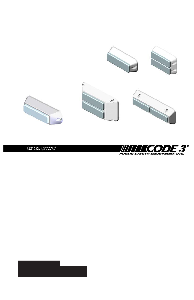
EXTERIOR LED
MODULES
LXEX1
LXEX2
LXEX125P
LED-EX SINGLE OR
DUAL EXTERIOR LED
Contents:
IMPORTANT:
LXEX64P
LXEX73P
MODULE
Introduction........................................................3
Features and Specifications............................3-4
Installation.......................................................5-6
Wiring.............................................................7-8
Programming..................................................8-9
Maintenance......................................................9
Warranty..........................................................12
Read all instructions and warnings before installing and using.
INSTALLER:
This manual must be delivered to the
end user of this equipment.
Page 2

WARNING!
The use of this or any warning device does not insure that all drivers can
or will observe or react to an emergency warning signal. Never take the
right-of-way for granted. It is your responsibility to be sure you can proceed
safely before entering an intersection, driving against traffic, responding at
a high rate of speed, or walking on or around traffic lanes.
The effectiveness of this warning device is highly dependent upon correct
mounting and wiring. Read and follow the manufacturer’s instructions before
!
WARNING!
installing or using this device. The vehicle operator should insure daily that
all features of the device operate correctly. In use, the vehicle operator
should insure the projection of the warning signal is not blocked by vehicle
components (i.e.: open trunks or compartment doors), people, vehicles, or
other obstructions. This equipment is intended for use by authorized
personnel only. It is the user’s responsibility to understand and obey all laws
regarding emergency warning devices. The user should check all
applicable city, state and federal laws and regulations.
Code 3 , Inc., assumes no liability for any loss resulting from the use of this
warning device. Proper installation is vital to the performance of this warning
device and the safe operation of the emergency vehicle. It is important to
recognize that the operator of the emergency vehicle is under psychological
and physiological stress caused by the emergency situation. The warning
device should be installed in such a manner as to: A) Not reduce the output
performance of the system, B) Place the controls within convenient reach
of the operator so that he can operate the system without losing eye contact
with the roadway.
Emergency warning devices often require high electrical voltages and/or
currents. Properly protect and use caution around live electrical connections. Grounding or shorting of electrical connections can cause high current
arcing, which can cause personal injury and/or severe vehicle damage,
including fire.
PROPER INSTALLATION COMBINED WITH OPERATOR TRAINING IN
THE PROPER USE OF EMERGENCY WARNING DEVICES IS ESSENTIAL TO INSURE THE SAFETY OF EMERGENCY PERSONNEL AND
THE PUBLIC.
This Product contains high intensity LED
!
devices. To prevent eye damage, DO NOT
stare into light beam at close range.
2
Page 3

Introduction:
The Exterior LED modules are weatherproof LED based warning light modules that contain
state-of-the-art high intensity LEDs. These products provide eight different operation modes
including a steady-burn mode. These products may be adapted to a variety of exterior
applications such as motorcycle applications, OEM fire truck, grill light and back-deck
applications. The exterior LED is available in either a +12V or a +24V version.
Features and Specifications:
Operating Voltage: 10-16Vdc (+12V version), 22-30Vdc (+24V version), Reverse
Polarity Protection. 50% Duty Cycle unless otherwise stated.
Flash Rate: 70 fpm minimum
Flash Modes (Flashing version only):
1. Cycle-Flash: Cycles through Triple, Quad, Double, and Fast
Single modes at approximately 109 fpm.
2. Triple-Flash: Three consecutive pulses per flash at
approxmately 83 fpm.
3. Quad-Flash: Four consecutive pulses per flash at
approximately 77 fpm.
4. Double-Flash: Two consecutive pulses per flash at
approximately 78 fpm.
5. Single-Flash: Single flash pattern at 75 fpm.
6. Quad-Flash 70% Duty Cycle: Can be used for NFPA.
7. Steady-burn: Continuous ON-state operation.
Flashing Current Draw: Red/Amber:
Single - .25A Avg.
Dual - .5A Avg.
Blue:
Single - .4A Avg.
Dual - .8A Avg.
Steady Burn Current Draw:Red/Amber:
Single - .5A A vg.
Dual - 1.0A Avg.
Blue:
Single - .8A A vg.
Dual - 1.6A Avg.
Available colors - Red, Amber or Blue or any combination for dual modules.
Available configurations - Single or dual light heads, Amber , Red, or Blue.
3
Page 4

Options:
The LED-EX is available in five basic models:
· LXEX1F- A single head unit. The housing is available in black or brushed
aluminum finish. The sealed cover lens is available in clear or colored to
match the LED light output.
· LXEX2F- A dual head (over under) unit. The housing is available in black or
brushed aluminum finish. The sealed cover lens is available in clear or
colored to match the LED light output. Each head is individually controlled.
· LXEX125P-A single head unit. The housing is available in highly polished
aluminum (chrome-like appearance).
· LXEX73P- A dual head (side by side) unit. The housing is available in highly
polished aluminum (chrome-like appearance). For retrofit purposes, the
mounting hole pattern matches the mounting hole pattern of a series 40 (7x3)
perimeter light.
· LXEX64P-A dual head (over under) unit. The housing is available in highly
polished aluminum (chrome-like appearance). For retrofit purposes, the
mounting hole pattern matches the mounting hole pattern of a series 60 (4x6)
perimeter light, and the periphery of the unit matches the periphery of an
OsciLaserTM lens.
In addition to the flashing models, The LED-EX1 is also available in two special function
versions:
The STT (Stop-Turn-Tail) version:
This version can be used as an Auxiliary stop-turn-tail light. When only the power (red)
and ground (black) wire are connected, the light will come on in a reduced intensity steady
burn tail-light mode. Grounding the white wire will result in a bright steady burn mode (stoplight) mode.
The steady-burning (non-flashing) version:
This version can be used as a stand-alone steady-burning light or be flashed with an LED
flasher such as Code 3 PSELED12. This model has only two wires, a power (red) wire
and a ground (black) wire.
4
Page 5

Installation:
Single Exterior LED Module (LXEX1, LXEX125P):
This unit can be mounted to metal surfaces using two #8 x 1/2 pan head sheet metal screws
(included). This unit can also be mounted to plastic surfaces using two #8 x 1/2 pan head
machine screws (included). An additional 0.25" minimum diameter mounting hole is needed to
mount the single exterior LED module. The cable routing hole can be drilled (Refer to Figure
as shown below). An optional mounting rubber gasket, included with the unit, may be used to
prevent oxidization and galvanization of the mounting surface due to metal-on-metal contact.
Figure 1 LXEX1
Figure 2 LXEX125
5
Page 6

Dual Exterior LED Module (LXEX2, LXEX73P, LXEX64P):
This unit can be mounted to metal surfaces using #8 x 1/2 pan head sheet metal screws
(included). This unit can also be mounted to plastic surfaces using #8 x 1/2 pan head
machine screws (included). Two additional 0.25" minimum diameter , or (1) .500" minimum
diameter mounting holes are drilled as shown in Figure below. An optional mounting rubber
gasket, included with the unit, may be used to prevent oxidization and galvanization of the
mounting surface due to metal-on-metal contact.
Figure 3 LXEX2F
Figure 4 LXEX73P
Figure 5 LXEX64P
6
Page 7

!
WARNING!
If the product is to be used inside the vehicle, it may cause severe personal
injury if not properly mounted and secured. Objects used in vehicle may
become airborne during a collision or other sudden changes in vehicle
speed or direction, such as braking, acceleration or turns.
Wiring:
Flashing Models:
Both single and dual LED-EX modules are equipped with a 8" long 3-wire cable harness
(two for dual modules). The user is required to furnish terminals to attach wires to meet
specific requirement.
Connect wires as follows:
1. Red wire: Power wire, connect to +12V (+24V for 24 volt version) voltage
line.
2. Black wire: GND wire, connect to ground terminal.
3. White wire: Control wire, may be left unconnected. It can also be connected to
GND through a momentary push-button switch, and be used for
programming the operation mode.
Note: The white wire should NOT be connected to a positive voltage
under any circumstances.
Note: It is possible to tie the red wires from both modules, and the black wires
from both modules when wiring the dual modules, provided that a properly
sized wire is used for the common connection. The white wires should not
be wired together if independent programming of the two heads is desired.
Note: The +24V versions will have a 24 volt label designating the unit for
operation on a +24 volt electrical system. The label will typically be
located on the back of the unit.
7
Page 8

STT (Stop-Turn-Tail) Models:
These models are equipped with a 8" long 3-wire cable harness. The user is required to
furnish terminals according to his or her preference. Connect the wires as follows:
1. Red wire: Power wire, connect to +12V voltage line.
2. Black wire: GND wire, connect to a ground terminal.
3. White wire: Stop-Light trigger input, grounding this wire will result in high-intensity
operation. This wire may be connected to an active low brake-light trigger
output if available.
Steady-Burning (Non-Flashing) Models:
These models are supplied with only two wires. Red power wire and black GND wire. The
third (white) wire is not available on these models.
Connect the wires as follows:
1. Red wire: Power wire, connect to +12V voltage line.
2. Black wire: GND wire, connect to Ground terminal.
Programming:
Programming the desired flash pattern (or operation mode ) is done with the white control
wire. Y ou can scroll through the eight available flash patterns, by momentarily grounding the
white control wire until you arrive at the desired operation mode. Momentary grounding of
the white wire can be accomplished either by momentarily touching the wire to GND, or
through a momentary push-button switch.
The unit will come on in the default Cycle-flash mode at the time of first power-up, until the
desired flash pattern is programmed. The default flash pattern can then be changed by
programming the desired pattern into the unit, the unit will continue to operate in the same
mode every time the unit is turned off and turned back on. The default flash pattern can be
changed at will for any number of times.
The unit can be reset back to the default flash pattern ( cycle-flash ) by grounding the control
wire for about 8-10 seconds and then releasing it. This can be done while operating in any
of the flash modes.
8
Page 9
Note: It is possible to program the two heads on the dual module individually as
shown on page 7. This should be done when a different flash pattern is
desired for each head. The two heads can also be programmed
simultaneously into the same flash pattern by tying the two white control
wires together then programming as shown on page 7.
Maintenance:
The Exterior LED Modules are completely sealed units designed to be trouble and
maintenance free. Refer to the guide below for help with troubleshooting. Should the unit be
diagnosed as malfunctioning, remove unit and replace with a new module.
LED module housings may become hot with
WARNING!
!
extended use. Allow modules to cool completely
before attempting to remove.
TROUBLESHOOTING
Problem Probable Cause Remedy
Lighthead does not
activate
Lighthead is constantly
ON
a. No Power to unit
b. Power input wire reversed
c. Damaged or shorted
cabling
d. Defective Lighthead
e. Control wire permanently
grounded or shorted to
GND
a. Control wire permanently
grounded or shorted to
GND
9
a. Check wiring for loose
connection
b. Reverse Power wires
c. Check cables for
damage
d. Replace lighthead module
e. Avoid permanent
grounding of control wire
a. Avoid permanent
grounding of control
wire
Page 10

Notes
10
Page 11

Notes
11
Page 12

WARRANTY
Code 3,®Inc.'s L.E.D. emergency devices are tested and found to be operational
at the time of manufacture. Provided they are installed and operated in accordance with
manufacturer's recommendations, Code 3, Inc. guarantees all parts and components
to a period of 5 years (unless otherwise expressed) from the date of purchase or
delivery, whichever is later. Units demonstrated to be defective within the warranty
period will be repaired or replaced at the factory service center at no cost.
Use of inappropriate or inadequate wiring or circuit protection causes this
warranty to become void. Failure or destruction of the product resulting from abuse or
unusual use and/or accidents is not covered by this warranty. Code 3, Inc. shall in no
way be liable for other damages including consequential, indirect or special damages
whether loss is due to negligence or breach of warranty.
CODE 3, INC. MAKES NO OTHER EXPRESS OR IMPLIED WAR-
RANTY INCLUDING, WITHOUT LIMITATION, WARRANTIES OF FITNESS
OR MERCHANTABILITY, WITH RESPECT TO THIS PRODUCT.
PRODUCT RETURNS
If a product must be returned for repair or replacement*, please contact our factory
to obtain a Return Goods Authorization Number (RGA number) before you ship the
product to Code 3, Inc. Write the RGA number clearly on the package near the mailing
label. Be sure you use sufficient packing materials to avoid damage to the product being
returned while in transit.
*Code 3, Inc. reserves the right to repair or replace at its discretion. Code 3, Inc. assumes no responsibility or liability for
expenses incurred for the removal and /or reinstallation of products requiring service and/or repair.; nor for the packaging,
handling, and shipping: nor for the handling of products return to sender after the service has been rendered.
For Technical Support / Service, please call 314-996-2800.
10986 N. Warson Road
www.code3pse.com
©2002 Code 3, Inc. Printed in USA
Code 3, Inc., a subsidiary of
Public Safety Equipment, Inc.
Code 3 is a registered trademark of Code
3, Inc.
St. Louis, Missouri 63114-2029—USA
Ph. (314) 426-2700 Fax (314) 426-1337
Revision 8, 11/05 - Instruction Book Part No. T05793
12
Code 3,®Inc.
 Loading...