

Page 1
INSTALLATION
& OPERATION
MANUAL
46STPKG
Stop/Tail/Turn/Reverse (in Bezel) Triple Stack Light (pair)
46STPKG
IMPORTANT:
Read all instructions and warnings before installing and using.
INSTALLER:This manual must be delivered to the end user of this equipment.
Contents:
General Description....................................................2
Installation & Mounting.................................................2
Electrical Connections..................................................3
Maintenance...............................................................3
Warranty.....................................................................4
1
Page 2

The use of this or any warning device does not ensure that all drivers can or will observe or react to an emergency warning signal. Never take
the right-of-way for granted. It is your responsibility to be sure you can proceed safely before entering an intersection, driving against traffic,
responding at a high rate of speed, or walking on or around traffic lanes.
!
WARNING
The effectiveness of this warning device is highly dependent upon correct mounting and wiring. Read and follow the manufacturer’s instructions before installing or using this device. The vehicle operator should insure daily that all features of the device operate correctly. In use, the
vehicle operator should insure the projection of the warning signal is not blocked by vehicle components (i.e., open trunks or compartment
doors), people, vehicles, or other obstructions.
This equipment is intended for use by authorized personnel only. It is the user’s responsibility to understand and obey all laws regarding
emergency warning devices. The user should check all applicable city, state and federal laws and regulations.
Code 3, Inc., assumes no liability for any loss resulting from the use of this warning device.
Proper installation is vital to the performance of this warning device and the safe operation of the emergency vehicle. It is important to recognize that the operator of the emergency vehicle is under psychological and physiological stress caused by the emergency situation. The
warning device should be installed in such a manner as to: A) Not reduce the output performance of the system; B) Place the controls within
convenient reach of the operator so that he can operate the system without losing eye contact with the roadway.
Emergency warning devices often require high electrical voltages and/or currents. Properly protect and use caution around live electrical
connections. Grounding or shorting of electrical connections can cause high current arcing, which can cause personal injury and/or severe
vehicle damage, including fire. Wait 10 minutes after turning off the power from system before touching any internal components. Always
wear hand and eye protection when handling electrical components.
To be an effective warning device, an emergency warning system produces bright light that can be hazardous to your eyesight when viewed
at close range. Do not stare directly into the light at close range or permanent damage to your eyesight may occur.
PROPER INSTALLATION COMBINED WITH OPERATOR TRAINING IN THE PROPER USE OF EMERGENCY WARNING DEVICES IS
ESSENTIAL TO INSURE THE SAFETY OF EMERGENCY PERSONNEL AND THE PUBLIC.
GENERAL DESCRIPTION
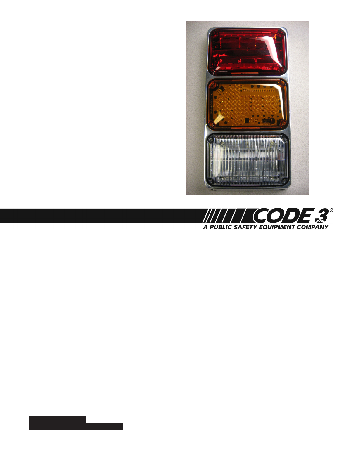
The 46STPKG is designed for mounting to the exterior of a vehicle. It consists of three lightheads stacked in a vertical arrangement in a bezel. On the
top is a brake/tail module. The middle is a turn arrow and the bottom is a reverse light. Packaged as a pair, be sure that the turn arrow is pointing
in the correct direction before mounting. This product is designed for operation on 12 Vdc and is intended to be mounted on the rear of a vehicle.
After unpacking the light, inspect it for damage that may have occurred in transit. The unit can be checked electrically by following the instructions in
the Electrical Connections section of this manual. If the unit has been damaged, do not attempt to install or operate it. File a claim immediately with the
carrier, stating the extent of damage. Carefully check all envelopes, shipping labels, and tags before removing or destroying them.
INSTALLATION & MOUNTING
For maximum coverage and effectiveness, each respective light assembly must be mounted in the orientation shown in Figure 1 (page 3). Make
certain that the drain hole in each bezel casting is orientated on the bottom prior to mounting.
Before proceeding with the installation, determine the approximate location of the light assembly and plan all cable/wire routing.
1. See Figure 1. Position the Triple Stack warning light assembly on the desired mounting surface. Ensure that the unit is level side to side.
Using the Triple Stack warning light assembly as a guide and the dimensions in Figure 1, scribe the four mounting hole locations and a wire routing
hole location on the mounting surface.
When drilling holes, check the area into which you are drilling to be sure you do not damage vehicle components. All drilled holes should be deburred and all sharp edges should be smoothed. All wire routings going through drilled holes should be protected by a grommet or convolute/split
loom tubing.
2. Drill four 9/64" (0.140") mounting holes and an appropriate sized wire routing hole at the previously scribed locations. The wire routing
hole should be large enough to accommodate all necessary user supplied wiring, connectors, and grommets.
3. The Triple Stack has wires that exit out the back of the unit for making electrical connections.
4. Complete the electrical connections for each respective Triple Stack light as described in “Electrical Connections.”
5. See Figure 1. Align the mounting gasket and Triple Stack warning light assembly over the previously drilled holes. Carefully place any wire
or connectors into the recessed area in the back of the aluminum bezel. Secure the assembly in position with the provided #10 x 3/4” screws.
2
Page 3

CABLE ROUTING
HOLE
5.75"
14.38"
Ø9/64" (4 PLACES)
#10 X 3/4"
SCREW(4)
QL64Z3V
MOUNTING
GASKET
VEHICLE
BODY
ELECTRICAL CONNECTIONS
The Triple Stack warning light assembly is designed to operate on 12 Vdc.
Three 12-inch long lead wires are supplied for making electrical
connections to the brake/tail light assembly.
Using 18-gauge (minimum) wire, connect the red (+) lead to the positive
power source terminal for BRAKE mode, and the white (+) lead to a
different positive power source terminal for TAIL mode. The black (–) lead
should be connected to the negative power source terminal.
Two 12-inch-long lead wires are supplied for making electrical connections
to the turn arrow and reverse light assemblies.
Using 18-gauge (minimum) wire, connect the red (+) lead to the positive
power source terminal and the black (–) lead to the negative power source
terminal.
MAINTENANCE
Figure 1.
Crazing (cracking) of the lenses will cause reduced effectiveness of the light. Do not use cleaning agents (which will cause crazing) such as strong detergents, solvents, or petroleum products. If crazing of the lenses does occur, the reliability of the light for
emergency signalling purposes may be reduced until the lenses are replaced.
To clean the plastic lenses, use a mild soap and a soft cloth. Remove fine scratches and haze with a non-abrasive, high quality, one-step, automotive
paste cleaner/wax and a soft cloth.
Larger wires and tight connections will provide longer service life for components. Do not use insulation displacement connectors
(e.g., 3M® Scotchlock type connectors). Route wiring using grommets and sealant when passing through compartment walls.
Minimize the number of splices to reduce voltage drop. High ambient temperatures (e.g., under-hood) will significantly reduce
!
WARNING
the current carrying capacity of wires, fuses, and circuit breakers. Use “SXL” type wire in engine compartment. All wiring should
conform to the minimum wire size and other recommendations of the manufacturer and be protected from moving parts and hot
surfaces. Looms, grommets, cable ties, and similar installation hardware should be used to anchor and protect all wiring.
Particular attention should be paid to the location and method of making electrical connections and splices to protect these
points from corrosion and loss of conductivity. Ground terminations should only be made to substantial chassis components,
preferably directly to the vehicle battery.
The user should install a fuse sized to approximately 125 percent of the maximum amperage capacity in the supply line and
each switched circuit to protect against short circuits. For example, a 30-ampere fuse should carry a maximum of 24 amperes.
DO NOT USE 1/4” DIAMETER GLASS FUSES AS THEY ARE NOT SUITABLE FOR CONTINUOUS DUTY IN SIZES ABOVE
15 amperes. Circuit breakers are very sensitive to high temperatures and will “false trip” when mounted in hot environments or
operated close to their capacity. Fuses or circuit breakers should be located as close to the power takeoff points as possible
and properly sized to protect the wiring and devices.
WARNING
Any electronic device may create or be affected by electromagnetic interference. After installation of any electronic
!
device, operate all equipment simultaneously to insure that operation is free of interference.
3
Page 4

WARRANTY
Code 3®, Inc.’s emergency devices are tested and found to be operational at the time of manufacture. Provided they are installed and
operated in accordance with manufacturer’s recommendations, Code 3®, Inc. guarantees all parts and components except the lamps to a period
of 1 year, LED Lighthead modules to a period of 5 years (unless otherwise expressed) from the date of purchase or delivery, whichever is later.
Units demonstrated to be defective within the warranty period will be repaired or replaced at the factory service center at no cost.
Use of a lamp or other electrical load of a wattage higher than installed or recommended by the factory, or use of inappropriate or
inadequate wiring or circuit protection causes this warranty to become void. Failure or destruction of the product resulting from abuse or unusual
use and/or accidents is not covered by this warranty. Code 3®, Inc. shall in no way be liable for other damages including consequential, indirect
or special damages whether loss is due to negligence or breach of warranty.
CODE 3®, INC. MAKES NO OTHER EXPRESS OR IMPLIED WARRANTY INCLUDING, WITHOUT LIMITATION, WARRANTIES OF
FITNESS OR MERCHANTABILITY, WITH RESPECT TO THIS PRODUCT.
PRODUCT RETURNS
If a product must be returned for repair or replacement*, please contact our factory to obtain a Return Goods Authorization
Number (RGA number) before you ship the product to Code 3®, Inc. Write the RGA number clearly on the package near
the mailing label. Be sure you use sufficient packing materials to avoid damage to the product being returned while in
transit.
*Code 3®, Inc. reserves the right to repair or replace at its discretion. Code 3®, Inc. assumes no responsibility or liability for expenses incurred for the removal and /or reinstallation of products requiring service and/or repair; nor for the packaging,
handling, and shipping: nor for the handling of products returned to sender after the service has been rendered.
Problems or Questions? Call The Technical Assistance HOTLINE - (314) 996-2800
Code 3, Inc.
www.code3pse.com
2562616A 111
Code 3 is a registered trademark of
Code 3, Inc.
St. Louis, Missouri 63114-2029—USA
Ph. (314) 426-2700 Fax (314) 426-1337
Revision 0, 1/2011 - Instruction Book Part No. T16488
©2011 Public Safety Equipment, Inc. Printed in USA
10986 N. Warson Road
Code 3,® Inc., a subsidiary of
Public Safety Equipment, Inc.
4
 Loading...